US7228693B2 - Controlling airflow in an air conditioning system for control of system discharge temperature and humidity - Google Patents
Controlling airflow in an air conditioning system for control of system discharge temperature and humidityDownload PDFInfo
- Publication number
- US7228693B2 US7228693B2US10/755,643US75564304AUS7228693B2US 7228693 B2US7228693 B2US 7228693B2US 75564304 AUS75564304 AUS 75564304AUS 7228693 B2US7228693 B2US 7228693B2
- Authority
- US
- United States
- Prior art keywords
- air
- space
- temperature
- controller
- source
- Prior art date
- Legal status (The legal status is an assumption and is not a legal conclusion. Google has not performed a legal analysis and makes no representation as to the accuracy of the status listed.)
- Expired - Lifetime
Links
- 238000004378air conditioningMethods0.000titleclaimsabstractdescription30
- 238000001816coolingMethods0.000claimsabstractdescription43
- 238000010438heat treatmentMethods0.000claimsabstractdescription39
- 230000000694effectsEffects0.000claimsabstractdescription25
- 238000000034methodMethods0.000claimsdescription24
- 239000012530fluidSubstances0.000claimsdescription15
- 239000003507refrigerantSubstances0.000claimsdescription15
- 230000006835compressionEffects0.000claimsdescription10
- 238000007906compressionMethods0.000claimsdescription10
- 230000000007visual effectEffects0.000claimsdescription5
- 230000001143conditioned effectEffects0.000claimsdescription4
- 239000002803fossil fuelSubstances0.000abstract1
- 238000010586diagramMethods0.000description10
- 238000007599dischargingMethods0.000description2
- 238000013459approachMethods0.000description1
- 238000002485combustion reactionMethods0.000description1
- 238000010304firingMethods0.000description1
- 239000000446fuelSubstances0.000description1
- 230000000977initiatory effectEffects0.000description1
- 238000009434installationMethods0.000description1
- 238000012986modificationMethods0.000description1
- 230000004048modificationEffects0.000description1
- 238000006467substitution reactionMethods0.000description1
- 238000011144upstream manufacturingMethods0.000description1
- XLYOFNOQVPJJNP-UHFFFAOYSA-NwaterChemical compoundOXLYOFNOQVPJJNP-UHFFFAOYSA-N0.000description1
Images


Classifications
- F—MECHANICAL ENGINEERING; LIGHTING; HEATING; WEAPONS; BLASTING
- F24—HEATING; RANGES; VENTILATING
- F24F—AIR-CONDITIONING; AIR-HUMIDIFICATION; VENTILATION; USE OF AIR CURRENTS FOR SCREENING
- F24F11/00—Control or safety arrangements
- F24F11/70—Control systems characterised by their outputs; Constructional details thereof
- F24F11/72—Control systems characterised by their outputs; Constructional details thereof for controlling the supply of treated air, e.g. its pressure
- F24F11/74—Control systems characterised by their outputs; Constructional details thereof for controlling the supply of treated air, e.g. its pressure for controlling air flow rate or air velocity
- F24F11/77—Control systems characterised by their outputs; Constructional details thereof for controlling the supply of treated air, e.g. its pressure for controlling air flow rate or air velocity by controlling the speed of ventilators
- F—MECHANICAL ENGINEERING; LIGHTING; HEATING; WEAPONS; BLASTING
- F24—HEATING; RANGES; VENTILATING
- F24F—AIR-CONDITIONING; AIR-HUMIDIFICATION; VENTILATION; USE OF AIR CURRENTS FOR SCREENING
- F24F11/00—Control or safety arrangements
- F24F11/62—Control or safety arrangements characterised by the type of control or by internal processing, e.g. using fuzzy logic, adaptive control or estimation of values
- F—MECHANICAL ENGINEERING; LIGHTING; HEATING; WEAPONS; BLASTING
- F24—HEATING; RANGES; VENTILATING
- F24F—AIR-CONDITIONING; AIR-HUMIDIFICATION; VENTILATION; USE OF AIR CURRENTS FOR SCREENING
- F24F11/00—Control or safety arrangements
- F24F11/70—Control systems characterised by their outputs; Constructional details thereof
- F24F11/72—Control systems characterised by their outputs; Constructional details thereof for controlling the supply of treated air, e.g. its pressure
- F24F11/74—Control systems characterised by their outputs; Constructional details thereof for controlling the supply of treated air, e.g. its pressure for controlling air flow rate or air velocity
- F24F11/76—Control systems characterised by their outputs; Constructional details thereof for controlling the supply of treated air, e.g. its pressure for controlling air flow rate or air velocity by means responsive to temperature, e.g. bimetal springs
- F—MECHANICAL ENGINEERING; LIGHTING; HEATING; WEAPONS; BLASTING
- F24—HEATING; RANGES; VENTILATING
- F24F—AIR-CONDITIONING; AIR-HUMIDIFICATION; VENTILATION; USE OF AIR CURRENTS FOR SCREENING
- F24F11/00—Control or safety arrangements
- F24F11/30—Control or safety arrangements for purposes related to the operation of the system, e.g. for safety or monitoring
- F—MECHANICAL ENGINEERING; LIGHTING; HEATING; WEAPONS; BLASTING
- F24—HEATING; RANGES; VENTILATING
- F24F—AIR-CONDITIONING; AIR-HUMIDIFICATION; VENTILATION; USE OF AIR CURRENTS FOR SCREENING
- F24F2110/00—Control inputs relating to air properties
- F—MECHANICAL ENGINEERING; LIGHTING; HEATING; WEAPONS; BLASTING
- F24—HEATING; RANGES; VENTILATING
- F24F—AIR-CONDITIONING; AIR-HUMIDIFICATION; VENTILATION; USE OF AIR CURRENTS FOR SCREENING
- F24F2110/00—Control inputs relating to air properties
- F24F2110/10—Temperature
- F—MECHANICAL ENGINEERING; LIGHTING; HEATING; WEAPONS; BLASTING
- F24—HEATING; RANGES; VENTILATING
- F24F—AIR-CONDITIONING; AIR-HUMIDIFICATION; VENTILATION; USE OF AIR CURRENTS FOR SCREENING
- F24F2110/00—Control inputs relating to air properties
- F24F2110/20—Humidity
- Y—GENERAL TAGGING OF NEW TECHNOLOGICAL DEVELOPMENTS; GENERAL TAGGING OF CROSS-SECTIONAL TECHNOLOGIES SPANNING OVER SEVERAL SECTIONS OF THE IPC; TECHNICAL SUBJECTS COVERED BY FORMER USPC CROSS-REFERENCE ART COLLECTIONS [XRACs] AND DIGESTS
- Y02—TECHNOLOGIES OR APPLICATIONS FOR MITIGATION OR ADAPTATION AGAINST CLIMATE CHANGE
- Y02B—CLIMATE CHANGE MITIGATION TECHNOLOGIES RELATED TO BUILDINGS, e.g. HOUSING, HOUSE APPLIANCES OR RELATED END-USER APPLICATIONS
- Y02B30/00—Energy efficient heating, ventilation or air conditioning [HVAC]
- Y02B30/70—Efficient control or regulation technologies, e.g. for control of refrigerant flow, motor or heating
Definitions
- the present inventionprovides systems and methods to control airflow rates in air conditioning systems to improve system operating efficiency, reduce discomfort from cold airflow into a controlled space on system startup, for example, control humidity in a space served by an air conditioning system and control discharge air temperature of a heating and/or cooling system.
- a forced airflow air conditioning systemis provided with a controller operably connected to a motor of a system air circulation blower, together with temperature sensors for sensing inlet air temperature to the system and discharge temperature from the system and whereby discharge temperature may be held constant or may be varied based on the sensed inlet air temperature to the system.
- a system and methodare providing for controlling discharge air temperature from a system operating in the cooling mode to provide improved humidity control and/or to lower system air discharge temperature.
- the systemcan be provided with a single sensor embedded in the heating/cooling coil of a heat pump or air handler operating as part of a vapor compression type heat exchange system.
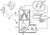
- FIG. 1is a somewhat schematic diagram of an air conditioning system including a motor driven blower, a heat exchanger and a control system in accordance with the invention
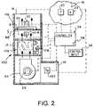
- FIG. 2is a schematic diagram of another version of an air conditioning system in accordance with the invention.
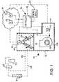
- FIG. 3is a flow diagram illustrating one method of operating an air conditioning system in accordance with the invention.
- FIG. 4is a flow diagram illustrating another method of operating an air conditioning system in accordance with the invention.
- FIG. 5is a flow diagram illustrating a further method of operating an air conditioning system in accordance with the invention.
- FIG. 6is a flow diagram illustrating yet another method of operating an air conditioning system in accordance with the invention.
- the system 10includes a cabinet 12 including an air inlet opening 14 and an air discharge opening 16 .
- the system 10is adapted to provide conditioned air to a controlled space 18 at which a temperature control sensor or thermostat 20 may be disposed.
- a second sensorcomprising a humidity sensor or humidistat 22 may also be disposed in the controlled space 18 , which space is operable to receive air discharged from the system 10 through the discharge opening 16 and to return air circulating from the space 18 to the system by way of the inlet opening 14 .
- the system 10includes a suitable air circulating blower 24 , preferably provided with a variable speed electric drive motor 26 , for circulating a variable flow rate of air through the system from the inlet opening 14 to the discharge opening 16 .
- a source of heating or cooling effectcomprising a heat exchanger 28 is disposed in the cabinet 12 downstream of the blower 24 for treating air flowing through the cabinet 12 prior to discharge back to the space 18 .
- the heat exchanger 28is preferably part of and connected to a vapor compression type refrigerant fluid flow circuit, including a conventional compressor 40 , a condenser 44 , a flow reversing valve 42 and conduits 46 and 48 connecting heat exchanger 28 to the remainder of the system.
- the flow circuit to which the heat exchanger 28 is connectedmay be a conventional vapor compression type cooling system or a heat pump whereby the heat exchanger 28 operates as an evaporator during cooling operation of the system 10 and as a heating coil when the system 10 is called upon to provide heat to the space 18 .
- Heat exchanger 28may be of a conventional fin and tube type and arranged in one or more sections, including the two section, so called A frame type illustrated.
- the system 10may include a return air temperature sensor 30 , preferably disposed in the cabinet 12 upstream of the blower 24 or in a suitable duct leading to the cabinet 12 from the space 18 .
- a discharge air temperature sensor 32is disposed downstream of the heat exchanger 28 , preferably within the cabinet 12 , for sensing the discharge temperature of air flowing through the air conditioning system 10 .
- Sensors 30 and 32 together with the thermostat 20 , the humidity sensor 22 and the motor 26are operably connected to a controller, generally designated by the numeral 34 for controlling operation of the system 10 .
- the controller 34may include a suitable micro-controller of a type known to those skilled in the art which may be programmed to operate in accordance with methods of the invention utilizing information received from the sensors 30 and 32 as well as the thermostat 20 and the humidity sensor 22 . Operation of the controller 34 may be modified by a suitable control input device 36 which may comprise a keypad, a touch screen control panel or other command or control signal input devices, not shown, known to those skilled in the art.
- the control circuit or controller 34may also include one or more visual display elements, such as a variable intensity light emitting diode (LED) 38 , as well as other visual display devices, also not shown, for displaying certain operating features of the system 10 including, for example, indication of the actual flow rate (i.e. cubic feet per minute) of air flowing through the system 10 .
- LEDvariable intensity light emitting diode
- Airis circulated through the cabinet 12 at a selected rate by blower 24 by varying the speed of the blower motor 26 to vary the speed of a suitable centrifugal fan, for example, not shown and drivenly connected to the motor. Air is circulated from the inlet opening 14 through the blower 24 then through the so called “A” frame type heat exchanger arrangement of the heat exchanger 28 and past the temperature sensor 32 to exit the cabinet 12 and, via suitable ducting, return to the space 18 . Air is, of course, circulated from the space 18 to the inlet opening 14 of cabinet 12 also via suitable ducting indicated schematically in FIG. 1 .
- the air conditioning system 10may be operated in a heating mode or cooling mode if the heat exchanger 28 is connected to the heat pump vapor compression system including the compressor 40 , the flow direction reversing valve 42 and the heat exchanger 44 in a conventional manner. Alternatively, the air conditioning system 10 may be operated in the heating mode or cooling mode alone if a reversing valve 42 is not provided in the refrigerant flow circuit.
- the flow circuitry of the system illustrated in FIG. 1is somewhat simplified and throttling valves or similar expansion devices as well as bypass check valves filters and accumulators have been eliminated from the drawing figure in the interest of conciseness.
- Compressor 40is preferably electric motor driven and controlled by controller 34 also.
- FIG. 3illustrates a somewhat simplified flow diagram for one method of operating the air conditioning system 10 .
- Controller 34is operable to sense the inlet and discharge temperatures at the sensors 30 and 32 , as indicated at step 56 , and the controller 34 may be pre-programmed to maintain a predetermined temperature differential between the sensors 30 and 32 which is controllable by energizing the blower motor 26 as indicated at step 58 .
- the inlet air temperature to system 10may be taken to be that which is sensed by the temperature sensor of thermostat 20 and sensor 30 could be eliminated, if desired.
- the blower motor 26may be energized at a predetermined minimum speed while the inlet temperature sensed at sensor 30 or thermostat 20 is compared with the discharges temperature sensed at sensor 32 , as indicated at step 60 . Accordingly, the controller 34 may then adjust the speed of the blower motor 26 at step 62 to maintain a preset temperature differential between sensors 30 and 32 . Steps 60 and 62 may be repeated every fifteen seconds, for example, as indicated at step 63 , until the heat or cooling effect called for by thermostat 20 is satisfied by the air conditioning system 10 at which time the blower motor may be de-energized until the thermostat 20 again calls for heating or cooling effect.
- FIG. 4Another mode of operating the system 10 is illustrated briefly in FIG. 4 , with the system 10 operating in the heating mode, that is with the heat exchanger 28 operating as a condenser.
- the system 10may be energized to operate in the heating mode at step 70 while inlet and discharge temperatures sensed at sensors 30 and 32 , or thermostat 20 and sensor 32 , are monitored and reported to the controller 30 at step 72 .
- Blower 24may be energized only when a predetermined temperature is sensed by sensor 32 , FIG. 1 , at step 72 or commensurate with the initiation of step 70 .
- blower speedis controlled to maintain a predetermined discharge temperature so that, upon startup, for example, of blower 24 it may be operated at minimum speed while the discharge temperature is sensed at sensor 32 and if the predetermined minimum discharge temperature is not registered, blower 24 may either be de-energized or operated at a minimum speed until it is indicated that the temperature sensed at sensor 32 is increasing beyond the predetermined discharge temperature.
- the programresiding in controller 34 and contemplated in accordance with the flow chart of FIG.
- step 78will carry out the step 78 of continuing to monitor temperatures at sensor 30 or thermostat 20 and sensor 32 and adjust blower speed to maintain airflow to the space 18 at a constant discharge temperature from the cabinet 12 .
- Such operationmay, of course, cause blower speed and airflow through the cabinet 12 to vary in order to maintain the predetermined discharge temperature.
- the rate of airflow across the heat exchanger 28may be controlled in accordance with the need for reduced humidity.
- the system 10may be energized in the cooling mode at step 84 and temperatures sensed at sensor 30 or thermostat 20 and sensor 32 at step 86 .
- Blower motor 26may be energized substantially simultaneously at step 88 .
- blower speedwill be adjusted to obtain lower humidity and/or discharge temperature sensed at sensor 32 in step 90 .
- blower speedwould be reduced in order to provide for greater heat exchange of the air flowing across the heat exchanger 28 while also permitting lower refrigerant temperatures of refrigerant fluid flowing through the heat exchanger 28 .
- Thermostat 20may also be operable to provide an input signal to controller 34 and the setpoint of the thermostat may be a controlling factor as well, once the ambient temperature in space 18 approaches the thermostat setpoint, to prevent discomfort from excess cooling being carried out by the system 10 when operating in accordance with the diagram of FIG. 5 .
- Step 90should be carried out on a substantially continuous basis as indicated at 91 in FIG. 5 .
- the system 100includes several components utilized in the system 10 including the variable speed motor driven blower 24 having a variable speed motor 26 and disposed within a cabinet 12 having an inlet opening 14 and a discharge opening 16 .
- An inlet air temperature sensor 102may be provided in the inlet duct portion of cabinet 12 which includes the opening 14 .
- Suitable ductingnot shown, provides for discharging air through opening 16 to space 18 and returning air from space 18 to system inlet opening 14 .
- a thermostat 20 and a humidity sensor 22may be provided in space 18 communicating with a controller 34 having a visual indicator 38 and a control input device or unit 36 operably connected thereto.
- the system 100differs from the system 10 primarily in the provision of a source of heating comprising a furnace 106 disposed in cabinet 12 and of conventional design.
- Furnace 106may be a combustion type and supplied with gaseous fuel via a controllable valve 108 for operation in a conventional manner.
- System 100may also include a second source of heating or cooling comprising a heat exchanger 110 comprising part of and suitably connected to a vapor compression fluid circuit essentially the same as shown in FIG. 1 but operable primarily in the cooling mode only.
- a temperature sensor 112is preferably mounted in very close proximity to the heat exchanger 110 or essentially contiguous with part of the heat exchanger structure to measure heat exchanger discharge temperature.
- Sensor 112is operably connected to controller 34 and to a control device 114 , such as a throttling valve, for controlling the flow of refrigerant fluid through the heat exchanger 110 .
- the sensor 112may operate in conjunction with the controller 34 and the control device 114 to maintain a predetermined constant temperature of the heat exchanger 110 and assist in maintaining a constant temperature of air being discharged through the opening 16 and returning to the space 18 .
- Other techniques for controlling the temperature of heat exchanger 110may be carried out.
- the system 100may be operated in accordance with the methods illustrated in FIGS. 3 , 4 and 5 and described hereinabove.
- the heat exchanger 110When operating in the heating mode, the heat exchanger 110 may be inactive and heat provided by forced airflow furnace 106 and controlled by controller 34 . If the system 110 is to be operated in the cooling mode, as illustrated in the method of FIG. 5 , furnace 106 would be deactivated and the vapor compression refrigerant fluid flow circuit shown in FIG. 1 , but associated with heat exchanger 110 would be operable to provide the lower humidity required by sensor 22 and/or a lower discharge temperature from the heat exchanger 110 .
- the blower 24may be operated at a constant or variable speed and the temperature sensor 112 may be operable through the controller 34 to control the flow of refrigerant fluid through the heat exchanger 110 to maintain a constant discharge temperature.
- the blower 24 in conjunction with the operation of the heat exchanger 110 and the associated refrigerant fluid flow systemcould eliminate the surge of cold or hot air that is often experienced when a heat pump type system initially starts up in the heating mode, as well as in the cooling mode.
- airflow ratemay be substantially constant but discharge temperature is also held constant in that the blower 24 is not energized until the discharge temperature of heat exchanger 110 achieves the value preset by controller 34 and this value is held by, for example, adjusting refrigerant flow at device 114 .
- Other methods of controlling the temperature of heat exchanger 110may be provided.
- system discharge temperaturecould also be held substantially constant by varying the firing rate of the furnace through suitable control of the valve 108 by the controller 34 . Accordingly, the process illustrated in FIG. 6 can be carried out by operation of the system 100 using the furnace 106 alone or using the vapor compression fluid system including the heat exchanger 110 operating with or without operation of furnace 106 .
Landscapes
- Engineering & Computer Science (AREA)
- Physics & Mathematics (AREA)
- Chemical & Material Sciences (AREA)
- Combustion & Propulsion (AREA)
- Mechanical Engineering (AREA)
- General Engineering & Computer Science (AREA)
- Fluid Mechanics (AREA)
- Fuzzy Systems (AREA)
- Mathematical Physics (AREA)
- Signal Processing (AREA)
- Air Conditioning Control Device (AREA)
Abstract
Description
In forced airflow air conditioning systems, a longstanding problem has been one of attempting to set the proper airflow rate for an air handler, furnace or heat pump or a combination thereof to match system capacity at the time of installation. This is a difficult and nettlesome problem to overcome and often the proper airflow is not set thereby causing poor system efficiency and discomfort to occupants of the space being served by the system.
For example, on startup of air conditioning systems, such as heat pumps, as well as systems which incorporate other types of heating sources, a constant speed circulating blower will deliver relatively cold air to the controlled space before the heat pump heating coil is at a stabilized operating condition and outputting sufficient heat to the controlled space. Thus, the occupants of the space will experience relatively cold air circulation and discomfort. In other situations, such as when operating in the cooling mode, it is desirable to adjust the air temperature of the system to improve humidity control and to provide lower system discharge temperatures. However, even if automatic control can be achieved to alleviate the problems described above, it is also desirable to provide for a system installer or service person to be able to adjust airflow rates to override any automatic settings of the system. It is to the above-mentioned ends that the present invention has been developed.
The present invention provides systems and methods to control airflow rates in air conditioning systems to improve system operating efficiency, reduce discomfort from cold airflow into a controlled space on system startup, for example, control humidity in a space served by an air conditioning system and control discharge air temperature of a heating and/or cooling system.
In accordance with one aspect of the present invention, a forced airflow air conditioning system is provided with a controller operably connected to a motor of a system air circulation blower, together with temperature sensors for sensing inlet air temperature to the system and discharge temperature from the system and whereby discharge temperature may be held constant or may be varied based on the sensed inlet air temperature to the system.
In accordance with another aspect of the invention, a system and method are providing for controlling discharge air temperature from a system operating in the cooling mode to provide improved humidity control and/or to lower system air discharge temperature. The system can be provided with a single sensor embedded in the heating/cooling coil of a heat pump or air handler operating as part of a vapor compression type heat exchange system.
The above noted aspects of the present invention together with other important advantages and superior features will be further appreciated by those skilled in the art upon reading the detailed description which follows in conjunction with the drawings.
In the description which follows like elements are marked throughout the specification and drawing with the same reference numerals, respectively. The drawing figures may be in somewhat schematic form and flow diagrams may show only major steps in accordance with the invention and may otherwise be abbreviated in the interest of clarity and conciseness.
Referring toFIG. 1 , there is illustrated an air conditioning system in accordance with the invention and generally designated by thenumeral 10. Thesystem 10 includes acabinet 12 including an air inlet opening14 and an air discharge opening16. Thesystem 10 is adapted to provide conditioned air to a controlledspace 18 at which a temperature control sensor orthermostat 20 may be disposed. A second sensor comprising a humidity sensor orhumidistat 22 may also be disposed in the controlledspace 18, which space is operable to receive air discharged from thesystem 10 through thedischarge opening 16 and to return air circulating from thespace 18 to the system by way of the inlet opening14.
Thesystem 10 includes a suitableair circulating blower 24, preferably provided with a variable speedelectric drive motor 26, for circulating a variable flow rate of air through the system from the inlet opening14 to thedischarge opening 16. A source of heating or cooling effect comprising aheat exchanger 28 is disposed in thecabinet 12 downstream of theblower 24 for treating air flowing through thecabinet 12 prior to discharge back to thespace 18. Theheat exchanger 28 is preferably part of and connected to a vapor compression type refrigerant fluid flow circuit, including aconventional compressor 40, acondenser 44, aflow reversing valve 42 andconduits heat exchanger 28 to the remainder of the system. The flow circuit to which theheat exchanger 28 is connected may be a conventional vapor compression type cooling system or a heat pump whereby theheat exchanger 28 operates as an evaporator during cooling operation of thesystem 10 and as a heating coil when thesystem 10 is called upon to provide heat to thespace 18.Heat exchanger 28 may be of a conventional fin and tube type and arranged in one or more sections, including the two section, so called A frame type illustrated.
Referring still further toFIG. 1 , thesystem 10 may include a returnair temperature sensor 30, preferably disposed in thecabinet 12 upstream of theblower 24 or in a suitable duct leading to thecabinet 12 from thespace 18. A dischargeair temperature sensor 32 is disposed downstream of theheat exchanger 28, preferably within thecabinet 12, for sensing the discharge temperature of air flowing through theair conditioning system 10.Sensors thermostat 20, thehumidity sensor 22 and themotor 26 are operably connected to a controller, generally designated by thenumeral 34 for controlling operation of thesystem 10. Thecontroller 34 may include a suitable micro-controller of a type known to those skilled in the art which may be programmed to operate in accordance with methods of the invention utilizing information received from thesensors thermostat 20 and thehumidity sensor 22. Operation of thecontroller 34 may be modified by a suitablecontrol input device 36 which may comprise a keypad, a touch screen control panel or other command or control signal input devices, not shown, known to those skilled in the art. The control circuit orcontroller 34 may also include one or more visual display elements, such as a variable intensity light emitting diode (LED)38, as well as other visual display devices, also not shown, for displaying certain operating features of thesystem 10 including, for example, indication of the actual flow rate (i.e. cubic feet per minute) of air flowing through thesystem 10.
Air is circulated through thecabinet 12 at a selected rate byblower 24 by varying the speed of theblower motor 26 to vary the speed of a suitable centrifugal fan, for example, not shown and drivenly connected to the motor. Air is circulated from the inlet opening14 through theblower 24 then through the so called “A” frame type heat exchanger arrangement of theheat exchanger 28 and past thetemperature sensor 32 to exit thecabinet 12 and, via suitable ducting, return to thespace 18. Air is, of course, circulated from thespace 18 to the inlet opening14 ofcabinet 12 also via suitable ducting indicated schematically inFIG. 1 . Theair conditioning system 10 may be operated in a heating mode or cooling mode if theheat exchanger 28 is connected to the heat pump vapor compression system including thecompressor 40, the flowdirection reversing valve 42 and theheat exchanger 44 in a conventional manner. Alternatively, theair conditioning system 10 may be operated in the heating mode or cooling mode alone if areversing valve 42 is not provided in the refrigerant flow circuit. The flow circuitry of the system illustrated inFIG. 1 is somewhat simplified and throttling valves or similar expansion devices as well as bypass check valves filters and accumulators have been eliminated from the drawing figure in the interest of conciseness.Compressor 40 is preferably electric motor driven and controlled bycontroller 34 also.
Another mode of operating thesystem 10 is illustrated briefly inFIG. 4 , with thesystem 10 operating in the heating mode, that is with theheat exchanger 28 operating as a condenser. With thesystem 10 enabled atstep 66 inFIG. 4 , with thethermostat 20 calling for heat atstep 68, thesystem 10 may be energized to operate in the heating mode atstep 70 while inlet and discharge temperatures sensed atsensors thermostat 20 andsensor 32, are monitored and reported to thecontroller 30 atstep 72.Blower 24 may be energized only when a predetermined temperature is sensed bysensor 32,FIG. 1 , atstep 72 or commensurate with the initiation ofstep 70. However, energization of theblower motor 26 atstep 74 would likely occur at minimum speed to avoid discharging cold air into thespace 18, that is, giving theheat exchanger 28 sufficient time to begin providing heat exchange with air resident in and flowing through thecabinet 12. In fact, atstep 76 inFIG. 4 , blower speed is controlled to maintain a predetermined discharge temperature so that, upon startup, for example, ofblower 24 it may be operated at minimum speed while the discharge temperature is sensed atsensor 32 and if the predetermined minimum discharge temperature is not registered,blower 24 may either be de-energized or operated at a minimum speed until it is indicated that the temperature sensed atsensor 32 is increasing beyond the predetermined discharge temperature. The program residing incontroller 34 and contemplated in accordance with the flow chart ofFIG. 4 will carry out thestep 78 of continuing to monitor temperatures atsensor 30 orthermostat 20 andsensor 32 and adjust blower speed to maintain airflow to thespace 18 at a constant discharge temperature from thecabinet 12. Such operation may, of course, cause blower speed and airflow through thecabinet 12 to vary in order to maintain the predetermined discharge temperature.
With thesystem 10 operating in the cooling mode, another method of operation may be carried out, as indicated inFIG. 5 , wherein the rate of airflow across theheat exchanger 28 may be controlled in accordance with the need for reduced humidity. For example, with thesystem 10 enabled in the cooling mode atstep 80 and, upon call for lower humidity by thehumidity sensor 22 atstep 82, thesystem 10 may be energized in the cooling mode atstep 84 and temperatures sensed atsensor 30 orthermostat 20 andsensor 32 atstep 86.Blower motor 26 may be energized substantially simultaneously atstep 88. However, blower speed will be adjusted to obtain lower humidity and/or discharge temperature sensed atsensor 32 instep 90.
For example, if the humidity as set atsensor 22 was required to be lowered, blower speed would be reduced in order to provide for greater heat exchange of the air flowing across theheat exchanger 28 while also permitting lower refrigerant temperatures of refrigerant fluid flowing through theheat exchanger 28. Thus, for the air being circulated through the heat exchanger28 a greater reduction in temperature and greater removal of water vapor from such flowing air would be achieved.Thermostat 20 may also be operable to provide an input signal tocontroller 34 and the setpoint of the thermostat may be a controlling factor as well, once the ambient temperature inspace 18 approaches the thermostat setpoint, to prevent discomfort from excess cooling being carried out by thesystem 10 when operating in accordance with the diagram ofFIG. 5 .Step 90 should be carried out on a substantially continuous basis as indicated at91 inFIG. 5 .
Referring now toFIG. 2 , an alternate embodiment of a system in accordance with the invention is illustrated and generally designated by the numeral100. Thesystem 100 includes several components utilized in thesystem 10 including the variable speed motor drivenblower 24 having avariable speed motor 26 and disposed within acabinet 12 having aninlet opening 14 and adischarge opening 16. An inlet air temperature sensor102 may be provided in the inlet duct portion ofcabinet 12 which includes theopening 14. Suitable ducting, not shown, provides for discharging air throughopening 16 tospace 18 and returning air fromspace 18 tosystem inlet opening 14. Athermostat 20 and ahumidity sensor 22 may be provided inspace 18 communicating with acontroller 34 having avisual indicator 38 and a control input device orunit 36 operably connected thereto.
Thesystem 100 differs from thesystem 10 primarily in the provision of a source of heating comprising afurnace 106 disposed incabinet 12 and of conventional design.Furnace 106 may be a combustion type and supplied with gaseous fuel via acontrollable valve 108 for operation in a conventional manner.System 100 may also include a second source of heating or cooling comprising aheat exchanger 110 comprising part of and suitably connected to a vapor compression fluid circuit essentially the same as shown inFIG. 1 but operable primarily in the cooling mode only. Atemperature sensor 112 is preferably mounted in very close proximity to theheat exchanger 110 or essentially contiguous with part of the heat exchanger structure to measure heat exchanger discharge temperature.Sensor 112 is operably connected tocontroller 34 and to acontrol device 114, such as a throttling valve, for controlling the flow of refrigerant fluid through theheat exchanger 110. Thesensor 112 may operate in conjunction with thecontroller 34 and thecontrol device 114 to maintain a predetermined constant temperature of theheat exchanger 110 and assist in maintaining a constant temperature of air being discharged through theopening 16 and returning to thespace 18. Other techniques for controlling the temperature ofheat exchanger 110 may be carried out.
Thesystem 100 may be operated in accordance with the methods illustrated inFIGS. 3 ,4 and5 and described hereinabove. When operating in the heating mode, theheat exchanger 110 may be inactive and heat provided by forcedairflow furnace 106 and controlled bycontroller 34. If thesystem 110 is to be operated in the cooling mode, as illustrated in the method ofFIG. 5 ,furnace 106 would be deactivated and the vapor compression refrigerant fluid flow circuit shown inFIG. 1 , but associated withheat exchanger 110 would be operable to provide the lower humidity required bysensor 22 and/or a lower discharge temperature from theheat exchanger 110.
In the embodiment ofFIG. 2 , and operating according to the method ofFIG. 6 , if theheat exchanger 110 is operating to supply cooling or heating effect alone, theblower 24 may be operated at a constant or variable speed and thetemperature sensor 112 may be operable through thecontroller 34 to control the flow of refrigerant fluid through theheat exchanger 110 to maintain a constant discharge temperature. In this way theblower 24 in conjunction with the operation of theheat exchanger 110 and the associated refrigerant fluid flow system could eliminate the surge of cold or hot air that is often experienced when a heat pump type system initially starts up in the heating mode, as well as in the cooling mode.
Accordingly, referring toFIG. 6 , when thesystem 100 is operating as described above and is enabled atstep 120, upon receipt of a call for heat and/or cooling bythermostat 20 atstep 122 thecompressor 40 would be energized, as indicated atstep 124, while the discharge temperature is sensed bysensor 112 and this information is furnished tocontroller 34 atstep 126. Once the discharge temperature sensed bysensor 112 reaches a predetermined value,blower 24 may be energized atstep 128 while discharge temperature is monitored bysensor 112 and refrigerant fluid flow is adjusted at thecontrol device 114 to maintain a constant discharge temperature forheat exchanger 110 atstep 130. This sensing and adjustment ofstep 130, repeated every fifteen seconds, as indicated atstep 132. Thus, in the embodiment ofFIG. 6 , airflow rate may be substantially constant but discharge temperature is also held constant in that theblower 24 is not energized until the discharge temperature ofheat exchanger 110 achieves the value preset bycontroller 34 and this value is held by, for example, adjusting refrigerant flow atdevice 114. Other methods of controlling the temperature ofheat exchanger 110 may be provided.
Of course, if thesystem 100 is operating with thefurnace 106 controlled by the gasflow control valve 108, system discharge temperature could also be held substantially constant by varying the firing rate of the furnace through suitable control of thevalve 108 by thecontroller 34. Accordingly, the process illustrated inFIG. 6 can be carried out by operation of thesystem 100 using thefurnace 106 alone or using the vapor compression fluid system including theheat exchanger 110 operating with or without operation offurnace 106.
Although several embodiments of an air conditioning system and method of operation of same have been described hereinabove in sufficient detail as to enable one skilled in the art to practice the invention, those skilled in the art will also recognize that various substitutions and modifications may be made without departing from the scope and spirit of the appended claims.
Claims (21)
1. An air conditioning system including:
a source of heating or cooling effect for transfer thereof to air to be conducted to an enclosed space;
a motor driven air blower for conducting air through said source of heating or cooling effect to change the temperature of air being conducted to said space;
at least one of a thermostat and humidity sensor disposed in said space for transmitting signals to a controller for said system, said controller being operably connected to a drive motor for said blower;
a first temperature sensor disposed for sensing the temperature of air being discharged from said source of heating or cooling effect; and
said controller being operable to energize said motor to conduct air from said space through said system and returned to said space at one of a constant temperature of air being discharged from said system to said space and reduced humidity sensed by said humidity sensor;
wherein said source of heating comprises a furnace including a control device for controlling the heat output from said furnace, said control device being operably connected to said controller.
2. The system set forth inclaim 1 wherein:
said motor is a variable speed motor and said controller is operable to vary the speed of said motor to vary the volume of airflow through said system to maintain said one of said constant discharge temperature and lower humidity, respectively.
3. The system set forth inclaim 1 including:
a second temperature sensor for sensing the temperature of air returning to said system from said space and for providing a temperature signal to said controller.
4. The system set forth inclaim 3 wherein:
said second temperature sensor comprises said thermostat.
5. The system set forth inclaim 1 wherein:
said source of heating or cooling effect comprises a vapor compression refrigerant fluid flow circuit including a heat exchanger for receiving airflow from said blower and to be returned to said space and said first temperature sensor is disposed directly adjacent said heat exchanger for sensing the temperature of said heat exchanger exposed to air flowing therethrough; and
a control device operably connected to said controller for maintaining a predetermined temperature sensed by said first temperature sensor.
6. The system set forth inclaim 1 including:
a visual indicator associated with said controller for indicating the flow rate of air flowing through said system.
7. The system set forth inclaim 1 wherein:
said controller is operably connected to a control input device for adjusting the discharge temperature set at said controller for controlling said one of said discharge temperature of air flowing to said space and said humidity in said space.
8. An air conditioning system including:
a source of cooling effect including a heat exchanger for cooling air to be conducted to an enclosed space;
a motor driven air blower for conducting air through said heat exchanger to reduce the temperature of air being conducted to said space;
a humidity sensor disposed in said space for transmitting signals to a controller for said system, said controller being operably connected to a drive motor for said blower;
a first temperature sensor disposed for sensing the temperature of air being discharged from said heat exchanger;
said controller being operable to energize said motor to conduct air from said space through said system and returned to said space at one of a constant temperature of air being discharged from said system to said space and reduced humidity sensed by said humidity sensor; and
a visual indicator associated with said controller for indicating the flow rate of air flowing through said system.
9. The system set forth inclaim 8 wherein:
said motor is a variable speed motor and said controller is operable to vary the speed of said motor to vary the volume of airflow through said system to maintain said one of said constant discharge temperature and lower humidity, respectively.
10. The system set forth inclaim 8 wherein:
said source of cooling effect comprises a vapor compression refrigerant fluid flow circuit including said heat exchanger for receiving airflow from said blower and to be returned to said space and said first temperature sensor is disposed directly adjacent said heat exchanger for sensing the temperature of said heat exchanger exposed to air flowing therethrough; and
a control device is operably connected to said controller for maintaining a predetermined temperature sensed by said first temperature sensor.
11. An air conditioning system including:
a source of heating effect for transfer thereof to air to be conducted to an enclosed space;
a motor driven air circulating blower for conducting air through said source of heating effect;
a thermostat disposed in said space for transmitting signals to a controller for said system, said controller being operably connected to a drive motor for said blower;
a first temperature sensor disposed for sensing the temperature of air being discharged from said source of heating effect;
a second temperature sensor for sensing the temperature of air returning to said system from said space and for providing a temperature signal to said controller;
comparing the temperatures sensed by the first and second temperature sensors; and
said controller being operable to energize said motor to conduct air from said space through said system and returned to said space at a constant temperature of air being discharged from said system to said space.
12. The system set forth inclaim 11 wherein:
said motor is a variable speed motor and said controller is operable to vary the speed of said motor to vary the volume of airflow through said system to maintain said constant discharge temperature.
13. The system set forth inclaim 11 wherein:
said second temperature sensor comprises said thermostat.
14. The system set forth inclaim 11 wherein:
said source of heating effect comprises a vapor compression refrigerant fluid flow circuit including a heat exchanger for receiving airflow from said blower and to be returned to said space.
15. The system set forth inclaim 14 wherein:
said first temperature sensor is disposed directly adjacent said heat exchanger for sensing the temperature of said heat exchanger exposed to air flowing therethrough.
16. The system set forth inclaim 15 including:
a control device operably connected to said controller for maintaining a predetermined temperature sensed by said first temperature sensor.
17. A method for operating an air conditioning system to supply conditioned air to a controlled space, said air conditioning system including a source of heating or cooling effect, a motor driven blower for conducting air through said system and in contact with said source of heating or cooling effect to condition air for return to said space, at least one of a thermostat and humidity sensor disposed for sensing air in said space and connected to a controller for controlling said blower, said method including the steps of:
responding to a signal from said thermostat calling for one of heating or cooling said space, energizing said system to provide one of heating or cooling effect by said source, energizing said blower to conduct air through said system from said space and returned to said space, sensing the discharge temperature of air flowing from said source;
adjusting one of the airflow through said system and the discharge temperature of air flowing from said source so as to provide one of maintaining a constant discharge temperature of air leaving said system and reducing the humidity in said space; and
providing a first temperature sensor for sensing temperature of air returning to said system from said space and a second temperature sensor for sensing the temperature of air flowing from said source; and
comparing the temperatures sensed by said sensors.
18. The method set forth inclaim 17 wherein:
the step of adjusting airflow through said system is carried out by varying the speed of said blower.
19. The method set forth inclaim 17 wherein:
said first temperature sensor is provided as said thermostat.
20. A method for operating an air conditioning system to supply conditioned air to a controlled space, said air conditioning system including a source of heating or cooling effect, a motor driven blower for conducting air through said system and in contact with said source of heating or cooling effect to condition air for return to said space, at least one of a thermostat and humidity sensor disposed for sensing air in said space and connected to a controller for controlling said blower, said method including the steps of:
responding to a signal from said thermostat calling for one of heating or cooling said space, energizing said system to provide one of heating or cooling effect by said source, energizing said blower to conduct air through said system from said space and returned to said space, sensing the discharge temperature of air flowing from said source;
adjusting one of the airflow through said system and the discharge temperature of air flowing from said source so as to provide one of maintaining a constant discharge temperature of air leaving said system and reducing the humidity in said space;
providing said source as a heat exchanger disposed in said system for flow of air thereover to be returned to said space and providing a temperature sensor at said heat exchanger for sensing the temperature of said heat exchanger exposed to said airflow thereover; and
controlling the flow of a fluid through said heat exchanger to modify the temperature sensed by said temperature sensor.
21. A method for operating an air conditioning system to supply conditioned air to a controlled space, said air conditioning system including a source of heating or cooling effect, a motor driven blower for conducting air through said system and in contact with said source of heating or cooling effect to condition air fro return to said space, at least one of a thermostat and humidity sensor disposed for sensing air in said space and connected to a controller for controlling said blower, said method including the steps of:
responding to a signal from said thermostat calling for one of heating or cooling said space, energizing said system to provide one of heating or cooling effect by said source, energizing said blower to conduct air through said system from said space and returned to said space, sensing the discharge temperature of air flowing from said source;
adjusting one of the airflow through said system and the discharge temperature of air flowing from said source so as to provide one of maintaining a constant discharge temperature of air leaving said system and reducing the humidity in said space;
providing said source as a heat exchanger disposed in said system for flow of air thereover to be returned to said space and providing a temperature sensor at said heat exchanger for sensing the temperature of said heat exchanger exposed to said airflow thereover; and
providing said heat exchanger as part of a refrigerant fluid flow circuit and adjusting the refrigerant fluid flow through said heat exchanger to provide one of control of humidity in said space and maintain a constant discharge temperature of air flowing from said system to said space.
Priority Applications (1)
| Application Number | Priority Date | Filing Date | Title |
|---|---|---|---|
| US10/755,643US7228693B2 (en) | 2004-01-12 | 2004-01-12 | Controlling airflow in an air conditioning system for control of system discharge temperature and humidity |
Applications Claiming Priority (1)
| Application Number | Priority Date | Filing Date | Title |
|---|---|---|---|
| US10/755,643US7228693B2 (en) | 2004-01-12 | 2004-01-12 | Controlling airflow in an air conditioning system for control of system discharge temperature and humidity |
Publications (2)
| Publication Number | Publication Date |
|---|---|
| US20050150238A1 US20050150238A1 (en) | 2005-07-14 |
| US7228693B2true US7228693B2 (en) | 2007-06-12 |
Family
ID=34739620
Family Applications (1)
| Application Number | Title | Priority Date | Filing Date |
|---|---|---|---|
| US10/755,643Expired - LifetimeUS7228693B2 (en) | 2004-01-12 | 2004-01-12 | Controlling airflow in an air conditioning system for control of system discharge temperature and humidity |
Country Status (1)
| Country | Link |
|---|---|
| US (1) | US7228693B2 (en) |
Cited By (27)
| Publication number | Priority date | Publication date | Assignee | Title |
|---|---|---|---|---|
| US20080133060A1 (en)* | 2006-11-30 | 2008-06-05 | Honeywell International Inc. | Hvac zone control panel with checkout utility |
| US20080133033A1 (en)* | 2006-11-30 | 2008-06-05 | Honeywell International Inc. | Hvac zone control panel |
| US20080128523A1 (en)* | 2006-11-30 | 2008-06-05 | Honeywell International Inc. | Hvac zone control panel |
| US20080133061A1 (en)* | 2006-11-30 | 2008-06-05 | Honeywell International Inc. | Hvac zone control panel |
| US20080134098A1 (en)* | 2006-11-30 | 2008-06-05 | Honeywell International Inc. | Hvac zone control panel |
| US20080134087A1 (en)* | 2006-11-30 | 2008-06-05 | Honeywell International Inc. | Hvac zone control panel |
| US20080223943A1 (en)* | 2007-03-15 | 2008-09-18 | Honeywell International Inc. | Variable Speed Blower Control In An HVAC System Having A Plurality of Zones |
| US20080251590A1 (en)* | 2007-04-13 | 2008-10-16 | Honeywell International Inc. | Hvac staging control |
| US20090308372A1 (en)* | 2008-06-11 | 2009-12-17 | Honeywell International Inc. | Selectable efficiency versus comfort for modulating furnace |
| US20090321041A1 (en)* | 2006-12-29 | 2009-12-31 | Geothermal Design Associates, Inc. | Multiple airflow pattern water source geothermal heat pump unit |
| US20100236262A1 (en)* | 2007-11-08 | 2010-09-23 | Carrier Corporation | Method and apparatus for improving dehumidification |
| US20110030395A1 (en)* | 2009-08-06 | 2011-02-10 | Hatton David L | Inlet air flow guide for acdx fan coil |
| US20110061408A1 (en)* | 2009-09-11 | 2011-03-17 | Tom Schnelle | Dehumidifiers for high temperature operation, and associated systems and methods |
| US7957839B2 (en) | 2006-12-29 | 2011-06-07 | Honeywell International Inc. | HVAC zone controller |
| US20120291463A1 (en)* | 2011-05-18 | 2012-11-22 | Technologies Holdings Corp. | Split System Dehumidifier |
| US20130261808A1 (en)* | 2012-03-30 | 2013-10-03 | John K. Besore | System and method for energy management of an hvac system |
| US8560127B2 (en) | 2011-01-13 | 2013-10-15 | Honeywell International Inc. | HVAC control with comfort/economy management |
| US8572994B2 (en) | 2009-04-27 | 2013-11-05 | Dri-Eaz Products, Inc. | Systems and methods for operating and monitoring dehumidifiers |
| US8784529B2 (en) | 2011-10-14 | 2014-07-22 | Dri-Eaz Products, Inc. | Dehumidifiers having improved heat exchange blocks and associated methods of use and manufacture |
| DE102013210175A1 (en)* | 2013-05-31 | 2014-12-18 | Siemens Aktiengesellschaft | Heat pump for use of environmentally friendly refrigerants |
| USD731632S1 (en) | 2012-12-04 | 2015-06-09 | Dri-Eaz Products, Inc. | Compact dehumidifier |
| US9205374B2 (en) | 2011-08-31 | 2015-12-08 | Dri-Eaz Products, Inc. | Dehumidifiers with improved fluid management and associated methods of use and manufacture |
| US9417005B1 (en)* | 2012-06-29 | 2016-08-16 | Mainstream Engineering Corporation | Retrofit device and method to improve humidity control of vapor compression cooling systems |
| US10174969B2 (en) | 2011-08-12 | 2019-01-08 | Lennox Industries Inc. | Furnace, a high fire ignition method for starting a furnace and a furnace controller configured for the same |
| US10684037B2 (en) | 2017-10-04 | 2020-06-16 | Trane International Inc. | Thermostat and method for controlling an HVAC system with remote temperature sensor and onboard temperature sensor |
| US10802459B2 (en) | 2015-04-27 | 2020-10-13 | Ademco Inc. | Geo-fencing with advanced intelligent recovery |
| US20240241098A1 (en)* | 2022-10-11 | 2024-07-18 | Honeywell International Inc. | Wall mountable sensor module with improved iaq sensor response time |
Families Citing this family (10)
| Publication number | Priority date | Publication date | Assignee | Title |
|---|---|---|---|---|
| DE102005057454B4 (en)* | 2005-12-01 | 2007-09-13 | Black Box Gmbh & Co.Kg | Airtight settlement agreement |
| US7628337B2 (en)* | 2006-06-08 | 2009-12-08 | Cuppetilli Robert D | Secondary heating system |
| CN103597291B (en)* | 2011-06-08 | 2017-03-01 | 三菱电机株式会社 | Refrigeration and air conditioning unit |
| CN103748421B (en) | 2011-06-29 | 2016-08-31 | 开利公司 | The method and system that coordinatograph flowing in heat exchanger system controls |
| CA2822146C (en)* | 2013-07-26 | 2016-09-20 | Julian Jameson | Air heater systems and control methods |
| EP2905584B2 (en)* | 2014-02-07 | 2020-08-26 | Blueair AB | Detachable sensor module for an air treatment device |
| JP2020106250A (en)* | 2018-12-28 | 2020-07-09 | ダイキン工業株式会社 | Combustion type heater and air-conditioning system |
| CN116086089B (en)* | 2023-02-24 | 2024-09-10 | 海信冰箱有限公司 | Refrigerator with a refrigerator body |
| CN116105422B (en)* | 2023-02-24 | 2024-09-10 | 海信冰箱有限公司 | Refrigerator with a refrigerator body |
| CN116026080B (en)* | 2023-02-24 | 2024-09-10 | 海信冰箱有限公司 | Refrigerator with a refrigerator body |
Citations (10)
| Publication number | Priority date | Publication date | Assignee | Title |
|---|---|---|---|---|
| US4003729A (en) | 1975-11-17 | 1977-01-18 | Carrier Corporation | Air conditioning system having improved dehumidification capabilities |
| US4257238A (en) | 1979-09-28 | 1981-03-24 | Borg-Warner Corporation | Microcomputer control for an inverter-driven heat pump |
| US4315413A (en) | 1979-12-31 | 1982-02-16 | Whirlpool Corporation | Selective temperature control system |
| US4899551A (en)* | 1984-07-23 | 1990-02-13 | Morton Weintraub | Air conditioning system, including a means and method for controlling temperature, humidity and air velocity |
| US4907416A (en)* | 1988-06-21 | 1990-03-13 | Diesel Kiki Co., Ltd. | Air-conditioner for automobiles |
| US5172565A (en)* | 1990-05-21 | 1992-12-22 | Honeywell Inc. | Air handling system utilizing direct expansion cooling |
| US5303561A (en)* | 1992-10-14 | 1994-04-19 | Copeland Corporation | Control system for heat pump having humidity responsive variable speed fan |
| US5516041A (en)* | 1993-06-30 | 1996-05-14 | Ford Motor Company | Method and control system for controlling an automotive HVAC system to prevent fogging |
| US5718372A (en) | 1997-03-17 | 1998-02-17 | Tishler; Carl | Temperature controller |
| US6826920B2 (en)* | 2002-12-09 | 2004-12-07 | Honeywell International Inc. | Humidity controller |
- 2004
- 2004-01-12USUS10/755,643patent/US7228693B2/ennot_activeExpired - Lifetime
Patent Citations (10)
| Publication number | Priority date | Publication date | Assignee | Title |
|---|---|---|---|---|
| US4003729A (en) | 1975-11-17 | 1977-01-18 | Carrier Corporation | Air conditioning system having improved dehumidification capabilities |
| US4257238A (en) | 1979-09-28 | 1981-03-24 | Borg-Warner Corporation | Microcomputer control for an inverter-driven heat pump |
| US4315413A (en) | 1979-12-31 | 1982-02-16 | Whirlpool Corporation | Selective temperature control system |
| US4899551A (en)* | 1984-07-23 | 1990-02-13 | Morton Weintraub | Air conditioning system, including a means and method for controlling temperature, humidity and air velocity |
| US4907416A (en)* | 1988-06-21 | 1990-03-13 | Diesel Kiki Co., Ltd. | Air-conditioner for automobiles |
| US5172565A (en)* | 1990-05-21 | 1992-12-22 | Honeywell Inc. | Air handling system utilizing direct expansion cooling |
| US5303561A (en)* | 1992-10-14 | 1994-04-19 | Copeland Corporation | Control system for heat pump having humidity responsive variable speed fan |
| US5516041A (en)* | 1993-06-30 | 1996-05-14 | Ford Motor Company | Method and control system for controlling an automotive HVAC system to prevent fogging |
| US5718372A (en) | 1997-03-17 | 1998-02-17 | Tishler; Carl | Temperature controller |
| US6826920B2 (en)* | 2002-12-09 | 2004-12-07 | Honeywell International Inc. | Humidity controller |
Cited By (55)
| Publication number | Priority date | Publication date | Assignee | Title |
|---|---|---|---|---|
| US9310091B2 (en) | 2006-11-30 | 2016-04-12 | Honeywell International Inc. | HVAC controller with checkout utility |
| US7913180B2 (en) | 2006-11-30 | 2011-03-22 | Honeywell International Inc. | HVAC zone control panel with mode navigation |
| US20080128523A1 (en)* | 2006-11-30 | 2008-06-05 | Honeywell International Inc. | Hvac zone control panel |
| US20080133061A1 (en)* | 2006-11-30 | 2008-06-05 | Honeywell International Inc. | Hvac zone control panel |
| US20080134098A1 (en)* | 2006-11-30 | 2008-06-05 | Honeywell International Inc. | Hvac zone control panel |
| US20080134087A1 (en)* | 2006-11-30 | 2008-06-05 | Honeywell International Inc. | Hvac zone control panel |
| US10429091B2 (en) | 2006-11-30 | 2019-10-01 | Ademco Inc. | HVAC controller with checkout utility |
| US10458670B2 (en) | 2006-11-30 | 2019-10-29 | Ademco Inc. | HVAC controller with checkout utility |
| US7558648B2 (en) | 2006-11-30 | 2009-07-07 | Honeywell International Inc. | HVAC zone control panel with zone configuration |
| US20080133060A1 (en)* | 2006-11-30 | 2008-06-05 | Honeywell International Inc. | Hvac zone control panel with checkout utility |
| US10145578B2 (en) | 2006-11-30 | 2018-12-04 | Honeywell International Inc. | HVAC controller with checkout utility |
| US7693591B2 (en) | 2006-11-30 | 2010-04-06 | Honeywell International Inc. | HVAC zone control panel with checkout utility |
| US20080133033A1 (en)* | 2006-11-30 | 2008-06-05 | Honeywell International Inc. | Hvac zone control panel |
| US20110077780A1 (en)* | 2006-11-30 | 2011-03-31 | Honeywell International Inc. | Hvac controller with checkout utility |
| US7693583B2 (en) | 2006-11-30 | 2010-04-06 | Honeywell International Inc. | HVAC zone control panel with constant function buttons |
| US10690367B2 (en) | 2006-11-30 | 2020-06-23 | Ademco Inc. | Zone control panel |
| US10101053B2 (en) | 2006-11-30 | 2018-10-16 | Honeywell International Inc. | HVAC controller with checkout utility |
| US7904830B2 (en) | 2006-11-30 | 2011-03-08 | Honeywell International Inc. | HVAC zone control panel |
| US10690365B2 (en) | 2006-11-30 | 2020-06-23 | Ademco Inc. | HVAC controller with checkout utility |
| US10612802B2 (en) | 2006-11-30 | 2020-04-07 | Ademco Inc. | Zone control panel with saving changes feature |
| US7957839B2 (en) | 2006-12-29 | 2011-06-07 | Honeywell International Inc. | HVAC zone controller |
| US8127566B2 (en)* | 2006-12-29 | 2012-03-06 | Geothermal Design Associates, Inc. | Multiple airflow pattern water source geothermal heat pump unit |
| US20090321041A1 (en)* | 2006-12-29 | 2009-12-31 | Geothermal Design Associates, Inc. | Multiple airflow pattern water source geothermal heat pump unit |
| US7766246B2 (en) | 2007-03-15 | 2010-08-03 | Honeywell International Inc. | Variable speed blower control in an HVAC system having a plurality of zones |
| US20080223943A1 (en)* | 2007-03-15 | 2008-09-18 | Honeywell International Inc. | Variable Speed Blower Control In An HVAC System Having A Plurality of Zones |
| US20080251590A1 (en)* | 2007-04-13 | 2008-10-16 | Honeywell International Inc. | Hvac staging control |
| US7819331B2 (en) | 2007-04-13 | 2010-10-26 | Honeywell International Inc. | HVAC staging control |
| US20100236262A1 (en)* | 2007-11-08 | 2010-09-23 | Carrier Corporation | Method and apparatus for improving dehumidification |
| US20090308372A1 (en)* | 2008-06-11 | 2009-12-17 | Honeywell International Inc. | Selectable efficiency versus comfort for modulating furnace |
| US10337747B2 (en)* | 2008-06-11 | 2019-07-02 | Ademco Inc. | Selectable efficiency versus comfort for modulating furnace |
| US9316413B2 (en)* | 2008-06-11 | 2016-04-19 | Honeywell International Inc. | Selectable efficiency versus comfort for modulating furnace |
| US20160209054A1 (en)* | 2008-06-11 | 2016-07-21 | Honeywell International Inc. | Selectable efficiency versus comfort for modulating furnace |
| US8572994B2 (en) | 2009-04-27 | 2013-11-05 | Dri-Eaz Products, Inc. | Systems and methods for operating and monitoring dehumidifiers |
| US9089814B2 (en) | 2009-04-27 | 2015-07-28 | Dri-Eaz Products, Inc. | Systems and methods for operating and monitoring dehumidifiers |
| US8567205B2 (en)* | 2009-08-06 | 2013-10-29 | David L. Hatton | Inlet air flow guide for ACDX fan coil |
| US20120273166A1 (en)* | 2009-08-06 | 2012-11-01 | Hatton David L | Inlet air flow guide for acdx fan coil |
| US8220281B2 (en)* | 2009-08-06 | 2012-07-17 | Hatton David L | Inlet air flow guide for ACDX fan coil |
| US20110030395A1 (en)* | 2009-08-06 | 2011-02-10 | Hatton David L | Inlet air flow guide for acdx fan coil |
| US20110061408A1 (en)* | 2009-09-11 | 2011-03-17 | Tom Schnelle | Dehumidifiers for high temperature operation, and associated systems and methods |
| US9645589B2 (en) | 2011-01-13 | 2017-05-09 | Honeywell International Inc. | HVAC control with comfort/economy management |
| US8560127B2 (en) | 2011-01-13 | 2013-10-15 | Honeywell International Inc. | HVAC control with comfort/economy management |
| US10473355B2 (en)* | 2011-05-18 | 2019-11-12 | Therma-Stor LLC | Split system dehumidifier |
| US20120291463A1 (en)* | 2011-05-18 | 2012-11-22 | Technologies Holdings Corp. | Split System Dehumidifier |
| US10174969B2 (en) | 2011-08-12 | 2019-01-08 | Lennox Industries Inc. | Furnace, a high fire ignition method for starting a furnace and a furnace controller configured for the same |
| US9205374B2 (en) | 2011-08-31 | 2015-12-08 | Dri-Eaz Products, Inc. | Dehumidifiers with improved fluid management and associated methods of use and manufacture |
| US8784529B2 (en) | 2011-10-14 | 2014-07-22 | Dri-Eaz Products, Inc. | Dehumidifiers having improved heat exchange blocks and associated methods of use and manufacture |
| US20130261808A1 (en)* | 2012-03-30 | 2013-10-03 | John K. Besore | System and method for energy management of an hvac system |
| US9417005B1 (en)* | 2012-06-29 | 2016-08-16 | Mainstream Engineering Corporation | Retrofit device and method to improve humidity control of vapor compression cooling systems |
| USD731632S1 (en) | 2012-12-04 | 2015-06-09 | Dri-Eaz Products, Inc. | Compact dehumidifier |
| DE102013210175A1 (en)* | 2013-05-31 | 2014-12-18 | Siemens Aktiengesellschaft | Heat pump for use of environmentally friendly refrigerants |
| US11473819B2 (en) | 2013-05-31 | 2022-10-18 | Siemens Energy Global GmbH & Co. KG | Heat pump for using environmentally compatible coolants |
| US10802459B2 (en) | 2015-04-27 | 2020-10-13 | Ademco Inc. | Geo-fencing with advanced intelligent recovery |
| US10684037B2 (en) | 2017-10-04 | 2020-06-16 | Trane International Inc. | Thermostat and method for controlling an HVAC system with remote temperature sensor and onboard temperature sensor |
| US20240241098A1 (en)* | 2022-10-11 | 2024-07-18 | Honeywell International Inc. | Wall mountable sensor module with improved iaq sensor response time |
| US12366564B2 (en)* | 2022-10-11 | 2025-07-22 | Honeywell International Inc. | Wall mountable sensor module with improved IAQ sensor response time |
Also Published As
| Publication number | Publication date |
|---|---|
| US20050150238A1 (en) | 2005-07-14 |
Similar Documents
| Publication | Publication Date | Title |
|---|---|---|
| US7228693B2 (en) | Controlling airflow in an air conditioning system for control of system discharge temperature and humidity | |
| AU739354B2 (en) | Method and apparatus for controlling supplemental heat in a heat pump system | |
| US6427461B1 (en) | Space conditioning system with outdoor air and refrigerant heat control of dehumidification of an enclosed space | |
| US5081846A (en) | Control of space heating and water heating using variable speed heat pump | |
| US5332028A (en) | Method and apparatus for controlling supplemental electric heat during heat pump defrost | |
| KR940008431B1 (en) | Method of controlling circuit in compressor of heat pump having variable velosity | |
| US20150362256A1 (en) | Advanced air terminal | |
| US9696067B2 (en) | Apparatus and method for controlling indoor airflow for heat pumps | |
| KR910012623A (en) | Heat pump type heating device and control method | |
| KR100681967B1 (en) | Air conditioning system with refrigerant charge treatment | |
| JPH01111168A (en) | Refrigerant heating type air conditioner | |
| US20230138109A1 (en) | Occupancy based method of operating a heat pump air conditioner unit | |
| JPH08178438A (en) | Engine heat pump | |
| JP3703594B2 (en) | Temperature controller for combined hot water heating system | |
| JP3154947B2 (en) | Hot water floor heating system controller | |
| JP6421880B2 (en) | Heat medium circulation system | |
| JP3128519B2 (en) | Temperature controller for combined hot water heating system | |
| JPH09273762A (en) | Control apparatus for floor heating system | |
| JP3425287B2 (en) | Control device for combined hot water heating system | |
| JP3369782B2 (en) | Vehicle air conditioner | |
| JP3483183B2 (en) | Temperature controller for combined hot water heating system | |
| JP3425306B2 (en) | Hot water heating system | |
| JP2919317B2 (en) | Control device for hot water heating system | |
| JPH01305268A (en) | Refrigerant heating type air conditioner | |
| JPH09112932A (en) | Controller for floor heating system |
Legal Events
| Date | Code | Title | Description |
|---|---|---|---|
| AS | Assignment | Owner name:AMERICAN STANDARD INTERNATIONAL, INC., NEW YORK Free format text:ASSIGNMENT OF ASSIGNORS INTEREST;ASSIGNOR:HELT, ROBERT W.;REEL/FRAME:014883/0210 Effective date:20040106 | |
| STCF | Information on status: patent grant | Free format text:PATENTED CASE | |
| AS | Assignment | Owner name:TRANE INTERNATIONAL INC., NEW YORK Free format text:CHANGE OF NAME;ASSIGNOR:AMERICAN STANDARD INTERNATIONAL INC.;REEL/FRAME:020733/0970 Effective date:20071128 Owner name:TRANE INTERNATIONAL INC.,NEW YORK Free format text:CHANGE OF NAME;ASSIGNOR:AMERICAN STANDARD INTERNATIONAL INC.;REEL/FRAME:020733/0970 Effective date:20071128 | |
| CC | Certificate of correction | ||
| CC | Certificate of correction | ||
| FPAY | Fee payment | Year of fee payment:4 | |
| FPAY | Fee payment | Year of fee payment:8 | |
| MAFP | Maintenance fee payment | Free format text:PAYMENT OF MAINTENANCE FEE, 12TH YEAR, LARGE ENTITY (ORIGINAL EVENT CODE: M1553); ENTITY STATUS OF PATENT OWNER: LARGE ENTITY Year of fee payment:12 |