US7227813B2 - Method and apparatus for forming multiple beams - Google Patents
Method and apparatus for forming multiple beamsDownload PDFInfo
- Publication number
- US7227813B2 US7227813B2US10/800,125US80012504AUS7227813B2US 7227813 B2US7227813 B2US 7227813B2US 80012504 AUS80012504 AUS 80012504AUS 7227813 B2US7227813 B2US 7227813B2
- Authority
- US
- United States
- Prior art keywords
- weighting
- time interval
- value
- output
- beams
- Prior art date
- Legal status (The legal status is an assumption and is not a legal conclusion. Google has not performed a legal analysis and makes no representation as to the accuracy of the status listed.)
- Expired - Fee Related, expires
Links
- 238000000034methodMethods0.000titleclaimsabstractdescription27
- 238000005070samplingMethods0.000claimsabstractdescription23
- 230000010363phase shiftEffects0.000claimsabstractdescription4
- 230000015654memoryEffects0.000claimsdescription27
- 230000001419dependent effectEffects0.000claimsdescription6
- 238000005303weighingMethods0.000claimsdescription2
- 230000008569processEffects0.000abstractdescription7
- 230000003111delayed effectEffects0.000abstractdescription3
- 238000010586diagramMethods0.000description8
- 230000008901benefitEffects0.000description2
- 230000017531blood circulationEffects0.000description2
- 230000009977dual effectEffects0.000description2
- 238000012986modificationMethods0.000description2
- 230000004048modificationEffects0.000description2
- 238000002604ultrasonographyMethods0.000description2
- 238000003491arrayMethods0.000description1
- 230000008859changeEffects0.000description1
- 230000001427coherent effectEffects0.000description1
- 230000001934delayEffects0.000description1
- 230000005670electromagnetic radiationEffects0.000description1
- 230000006870functionEffects0.000description1
- 238000012805post-processingMethods0.000description1
- 238000012545processingMethods0.000description1
Images


Classifications
- G—PHYSICS
- G01—MEASURING; TESTING
- G01S—RADIO DIRECTION-FINDING; RADIO NAVIGATION; DETERMINING DISTANCE OR VELOCITY BY USE OF RADIO WAVES; LOCATING OR PRESENCE-DETECTING BY USE OF THE REFLECTION OR RERADIATION OF RADIO WAVES; ANALOGOUS ARRANGEMENTS USING OTHER WAVES
- G01S15/00—Systems using the reflection or reradiation of acoustic waves, e.g. sonar systems
- G01S15/88—Sonar systems specially adapted for specific applications
- G01S15/89—Sonar systems specially adapted for specific applications for mapping or imaging
- G01S15/8906—Short-range imaging systems; Acoustic microscope systems using pulse-echo techniques
- G01S15/8909—Short-range imaging systems; Acoustic microscope systems using pulse-echo techniques using a static transducer configuration
- G—PHYSICS
- G01—MEASURING; TESTING
- G01S—RADIO DIRECTION-FINDING; RADIO NAVIGATION; DETERMINING DISTANCE OR VELOCITY BY USE OF RADIO WAVES; LOCATING OR PRESENCE-DETECTING BY USE OF THE REFLECTION OR RERADIATION OF RADIO WAVES; ANALOGOUS ARRANGEMENTS USING OTHER WAVES
- G01S7/00—Details of systems according to groups G01S13/00, G01S15/00, G01S17/00
- G01S7/52—Details of systems according to groups G01S13/00, G01S15/00, G01S17/00 of systems according to group G01S15/00
- G01S7/52017—Details of systems according to groups G01S13/00, G01S15/00, G01S17/00 of systems according to group G01S15/00 particularly adapted to short-range imaging
- G01S7/52085—Details related to the ultrasound signal acquisition, e.g. scan sequences
- G01S7/5209—Details related to the ultrasound signal acquisition, e.g. scan sequences using multibeam transmission
- H—ELECTRICITY
- H01—ELECTRIC ELEMENTS
- H01Q—ANTENNAS, i.e. RADIO AERIALS
- H01Q25/00—Antennas or antenna systems providing at least two radiating patterns
Definitions
- the present inventionrelates to beam forming, and more particularly, to forming multiple beams using time division multiplexing.
- transmitting/receiving elementsare placed in an array. Some or all of the elements of the array emit pulses of electromagnetic radiation or sound toward a target, and reflections from the target are received at all of the elements. Since the received signals arrive at different times at each element, if the signals are summed at a given time, then some signals will be in phase and some will be out of phase. The summation will be less than the maximum amplitude possible. To receive the maximum amplitude possible, the received signals from all the elements are focused into a beam.
- a beamis amplitude or power as a function of angle (position).
- Beam formingis a linear operation on the signals received from the array of elements, combining them with delays (weights). The first element will be delayed a certain amount of time/phase, the second element a different amount of time/phase, etc., so that all peaks will line up at the same phase.
- One technique of weighting elementsis to represent each received signal as a complex phasor with a real and imaginary (quadrature) component. The complex representation of the received signal is multiplied (weighted) by a complex weight which shifts the phase of the received waveform by the desired amount of delay.
- One reason for calculating multiple beamsis to map a given volume at various points, one beam for each point. Another reason for calculating multiple beams is to reduce the number of elements necessary to gain an accurate picture of a position from several antenna/transducer elements.
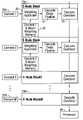
- FIG. 1 of the present applicationThe technique in the prior art for forming multiple beams is shown in FIG. 1 of the present application.
- the received reflected signal from each elementis first sampled for a period of time and digitized (not shown) via analog-to-digital converters (A/D converters) 10 a through 10 m , one for each of the elements 1 through M.
- A/D convertersanalog-to-digital converters
- Each of the outputs of the A/D convertersis fed to separate, parallel beam forming networks 12 a through 12 n , one for each of the N beams to be formed.
- each A/D converter outputis fed to beam forming weighting networks 14 a through 14 m , and then a beam combining network 16 .
- Having a separate beam forming network for each beamis costly in terms of hardware needed, and it does not scale with requirements (it may not be possible to add more hardware to a circuit board).
- the present inventionincludes a system for forming a plurality of beams from a reflected signal received by a transducer array having first and second receiver elements, each of said first and second receiver elements receiving the reflected signal at a phase dependent upon the position of the first receiver element relative to the second.
- the received signal at each of the first and second receiver elementsis sampled and converted to a digital signal by first and second associated analog-to-digital converters at a sampling rate defining a time interval during which a first value representing the amplitude of the received signal at the first receiver element and a second value representing the amplitude of the received signal at the second receiver are available during the time interval.
- the systemincludes a time division multiplexer for sequentially applying first and second weighting factors to the first value to generate first and second resultants for forming first and second beams, respectively.
- the time division multiplexersequentially applies third and fourth weighting factors to the second value to generate third and fourth resultants for forming the first and second beams.
- a combinercombines the first and third resultants and the second and fourth resultants for forming the first and second beams, respectively.
- a plurality of beamsis formed from a reflected signal received by a transducer array having first and second receiver elements.
- Each of the first and second receiver elementsreceive the reflected signal at a phase dependent upon the position of the first receiver element relative to the second, the received signal at each of the first and second receiver elements being sampled and converted to a digital signal by first and second associated analog-to-digital converters at a sampling rate defining a time interval during which a first value representing the amplitude of the received signal at the first receiver element and a second value representing the amplitude of the received signal at the second receiver are available during the time interval.
- a first weighting factoris applied to the first value during a first portion of the time interval to generate a first resultant for a first beam for the first receiver element.
- a second weighting factoris applied to the first value during a second portion of the time interval, generating a second resultant for a second beam for the first receiver element.
- a third weighting factoris applied to the second value during a third portion of the time interval to generate a third resultant for a first beam for the second receiver element.
- a fourth weighing factoris applied to the second value during a fourth portion of the time interval, generating a fourth resultant for a second beam for the second receiver element. The first and third resultants are combined to generate the first beam; and the second and fourth resultants are combined to generate the second beam.
- FIG. 1depicts parallel beam forming networks of the prior art
- FIGS. 2A and 2Bdepict a time flow diagram of time division multiplexed beam forming of the present invention, with FIG. 2B being a continuation of FIG. 2A , as shown;
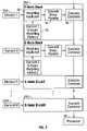
- FIG. 3depicts a block diagram of an exemplary embodiment of the present invention
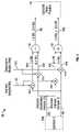
- FIG. 4depicts a first embodiment of a weighting applicator which is shown as blocks in FIG. 3 ;
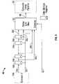
- FIG. 5depicts a second embodiment of a weighting applicator which is shown as blocks in FIG. 3 ;
- FIG. 6depicts a first embodiment of a weighting memory when there is only one constant depth of focus
- FIG. 7depicts the layout of the first embodiment of a weighting memory when there is only one depth of focus
- FIG. 8depicts a second embodiment of a weighting memory when there are R depths of focus
- FIG. 9depicts the layout of the second embodiment of a weighting memory when there are R depths of focus
- FIG. 10depicts a block diagram of a cascade delay pipeline
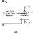
- FIG. 11depicts a block diagram of a cascade combiner.
- the present inventionreduces the part count and cost of the prior art beam forming networks by replacing the separate parallel networks with a single network, which uses time division multiplexing. Instead of having several parallel sets of beam forming network hardware running at a given sampling clock rate, a simpler single piece of hardware is run at a faster rate equal to the given sampling clock rate times the number of beams to be formed.
- Each sample received from each elementis time division multiplexed into a bit stream, one for each beam. These time division multiplex element samples are weighted to apply the desired phase shift/time delay per element.
- Each weighted resultantis delayed in a cascade delay pipeline and then combined with a cascade combiner to form a beam at a given time division instant. This process is repeated for the next set of time division multiplexed samples and weights from each element of the array at a given time to form the next beam. The process is repeated for all beams until the sampling time interval ends.
- This technique of and apparatus for forming multiple beams for locating an object using wave propagationare applicable to many fields such as sonar, radar, ultrasound, and telecommunications.
- FIG. 2a time flow diagram of a time division multiplexed beam forming network of the present invention is depicted.
- the array of M elementsoutputs of A/D converters from antennas/transducers) to be sampled is depicted along vertical axis 20 .
- the horizontal axis 24represents the flow of time.
- a total of k sampling periodsare depicted along the horizontal axis, where k extends indefinitely into the future.
- N parallel networksconsisting of the same beam forming hardware would be sampling the signals from each element for the entire length of time interval T for k time intervals to generate N beams.
- the sample magnitudeis referenced by 22 ana for sampling period ⁇ N .
- the Mth element for beam 1is sampled by the beam forming hardware, while at 22 mna , the Mth element is sampled for the Nth beam.
- the beam forming hardware of the present inventiontakes each of the samples from each of the elements and “weights” (e.g., complex multiplies) each sample magnitude (amplitude, power, etc.) Ai by a weight wi, and then combines (e.g. sums) each weighted-sample to form a coherent beam, e.g.
- weightse.g., complex multiplies
- Beam 1(using 22 aaa , 22 aba , . . . , 22 ama ).
- the method used for selecting the weightsis known in the prior art. This process is repeated for Beam 2 through N during time period 1 , and then again for time periods 2 through k, and so on.
- N beamsare reconstructed for each time period of the sampling hardware.
- the beam forming hardwareruns at a faster sampling rate N*Fs Hertz to form N beams in time. To increase the number of beams, one need only run the beam forming hardware at a rate proportional to the number of beams desired, instead of adding more hardware as required by the prior art systems described above in FIG. 1 .
- FIG. 3a block diagram of an exemplary embodiment of the present invention is depicted.
- This techniquereplaces the separate beam forming networks of the prior art described above in FIG. 1 with simpler blocks 28 a through 28 m of repeated design, one per element 26 a through 26 m of the M element, called E-nodes.
- Groups of E-node blocks 28 a through 28 mcan be implemented in an ASIC (application specific integrated circuit), FPGA (field programmable gate array), or even in a digital signal processor algorithm.
- ASICapplication specific integrated circuit
- FPGAfield programmable gate array
- Each of E-node blocks 28 a through 28 mis composed of a weighting applicator 30 , a weighting memory 32 , cascade delay pipeline 34 , and cascade combiner 36 .
- the components of E-Node block 28 aare running at N*Fs Hz where Fs is the element 26 a sampling rate and N is the number of beams to be formed.
- Weighting memory 32is cycled through N weights per element sampling period T seconds to create N weighted resultants, one for each of the N beams, with the weighting applicator 30 .
- the process of combining or summing each of the these resultants from the M element samples per beamis accomplished by cascading the resultants from each E-Node block through cascade delay pipeline 34 and cascade combiner 36 .
- the final N beamsare presented to processor 38 for post processing algorithms and display.
- FIG. 4shows a weighting applicator utilizing complex inputs and outputs, including in-phase and quadrature components, going to and coming from sub-blocks 26 a , 30 , 34 , and 36 of FIGS. 3 , 6 , 8 , 10 , and 11
- FIG. 5shows only one input/output passing between blocks 26 a , 30 , 34 , and 36 .
- the single input/outputs of sub-blocks as depicted in FIGS. 3 , 6 , 8 , 10 , and 11represent either the one or two input/output architectures.
- a first embodiment weighting applicator 30is depicted.
- complex phasor multiplicationis used to achieve the required phase shift for aligning each received signal sample, e.g., from element 26 a .
- the received sample from element 26 acontains a real (in-phase) component I appearing at complex weighting multiplier input 40 i , and imaginary (quadrature) component Q appearing at complex weighting multiplier input 40 q .
- the weight loaded from weighting memory 32has in-phase component Wi appearing at complex weighting multiplier input 42 i , and imaginary (quadrature) component Wq appearing at complex weighting multiplier input 42 q .
- Input 40 iis fed to multipliers 44 a and 44 d ; input 40 q is fed to multipliers 44 b and 44 c ; input 42 q is fed to multipliers 44 b and 44 d , and input 42 i is fed to multipliers 44 a and 44 c .
- Multiplier 44 aproduces intermediate result 46 a ; multiplier 44 b produces intermediate result 46 b ; multiplier 44 c produces intermediate result 46 c ; and multiplier 44 d produces intermediate result 46 d .
- Two of these intermediate results 46 a and 46 bare subtracted at difference element 48 producing real output 50 i , while intermediate results 46 c and 46 d are added in summing element 52 to produce imaginary (quadrature) output 50 r .
- Outputs 50 i and 50 rare fed to output sample cascade delay pipeline 34 .
- FIG. 5a second embodiment of weighting applicator 30 is depicted. Instead of multiplying complex phasors as in FIG. 4 , a delay is used to align components of a beam.
- the received sample from e.g., element 26 ais fed into element sample input 54 of weighting applicator 30 .
- Sample input 54passes sequentially through a series of storage registers 56 a through 56 z (as shown by shifts to the right), whose outputs 58 a through 58 z are fed to delay line mux (multiplexer) selector 60 .
- Each shift through the storage registers 56 a through 56 zimparts a certain amount of delay to sample input 54 .
- Storage registers 56 a through 56 zare clocked by input sample clock input 62 at a rate equal to the input sampling frequency.
- One of outputs 58 a through 58 zwhich is selected by delay line mux selector 60 via selector input 64 , represents the total delay desired to line up a signal sample, e.g. from element 26 a , to a desired phase (depending on the beam to be selected, the particular element sampled, and the depth of focus desired).
- Weighting factor wi stored in weight memory 32may be translated (not shown) to the value to be placed on selector input 64 .
- the selector input 64is clocked at the input sampling frequency times the number of beams.
- the output 66 of mux selector 60is fed to output sample cascade delay pipeline 34 .
- a first embodiment of the weighting memory 32is depicted when there is only one constant depth of focus.
- Sample clock input 68is fed to the inputs of Modulo (N) Address Counter 70 and storage register 72 , where N is the number of beams.
- Modulo (N) Address Counter 70generates and applies read address 74 to Memory 76 , which can be ROM, RAM, Dual Port RAM, etc.
- the weight addressed by read address 70is latched into storage register 72 via memory output 78 .
- the output of storage register 72is fed to weighting applicator 30 .
- each weight 80is stored sequentially based on beam number for each element (M), for a total of M samples times N beams worth of weight data and repeated each sample period.
- FIG. 8a second embodiment of the weighting memory 32 is depicted when there are R depths of focus.
- Sample clock input 68is fed to the inputs of Modulo (N) Address Counter 82 and storage register 84 , where N is the number of beams.
- Modulo (N) Address Counter 82there is also a Modulo (R) Range Depth Counter 86 , with its own Range Focus Depth Enable clock input 88 .
- the output 90 of Modulo (N) Address Counter 82 and the output 92 of Modulo (R) Range Depth Counter 86are combined in node 94 to provide a read address 96 to Memory 98 .
- Memory 98can be ROM, RAM, Dual Port RAM, etc.
- the weight addressed by read address 96is latched into storage register 84 via memory output 100 .
- the output of storage register 84is fed to weighting applicator 30 .
- each weight 102is stored sequentially based on beam number and range focus.
- the memory 32dwells on a set of N beam weights for a set period of time called a depth of focus. The depth of focus period determines at what sample the beam weights change to the next set of N beam weights. After the depth of focus dwell is completed, the memory 32 address is updated to the next range of focus. This process repeats until all ranges of focus have been visited.
- FIG. 10a block diagram of cascade delay pipeline 34 is depicted.
- the output of weighting applicator 30is fed to input 104 of cascade delay pipeline 34 .
- Input 104passes through a series of connected storage registers 106 a through 106 z , whose outputs 108 a through 108 z are fed to cascade delay pipeline mux 110 .
- Each shift of data through storage registers 106 a through 106 zimparts a certain amount of delay to input 104 .
- Storage registers 106 a through 106 zare clocked at input sample clock input 68 at a rate equal to the sampling frequency times the number of beams.
- One of outputs 108 a through 108 zis selected by cascade delay pipeline mux 110 via selector input 112 .
- the outputis selected relative to the E-Node block/sample in the summing tree. Early E-node blocks have less delay. Later E-Node blocks require more delay for proper time alignment between E-nodes. The delay imparted is hardware dependent, and is not related to the sampled signal itself.
- the output 114 of mux 110is fed to cascade combiner 36 .
- FIG. 11a block diagram of cascade combiner 36 is depicted.
- Output 114 of cascade delay pipeline 34is fed to summing node 116 .
- Also fed to summing node 116is the output of the cascade delay pipeline 118 of the previous E-node.
- Summing node 116is clocked at the number of beams times the sample frequency at input 68 .
- Output 120 of summing node 116is fed to the cascade combiner sub-block of the next E-node block in the chain.
- FIGS. 2 through 11scales up in many dimensions depending on the end requirements. If large arrays are used, then the beam forming network shall consist of multiple copies of the processing node engine 28 a through 28 m.
Landscapes
- Engineering & Computer Science (AREA)
- Physics & Mathematics (AREA)
- Radar, Positioning & Navigation (AREA)
- Remote Sensing (AREA)
- Acoustics & Sound (AREA)
- Computer Networks & Wireless Communication (AREA)
- General Physics & Mathematics (AREA)
- Ultra Sonic Daignosis Equipment (AREA)
- Measurement Of Velocity Or Position Using Acoustic Or Ultrasonic Waves (AREA)
- Radar Systems Or Details Thereof (AREA)
- Variable-Direction Aerials And Aerial Arrays (AREA)
Abstract
Description
(I+jQ)(Wi+jWq)=(IWi−QWq)+j(IWq+QWi) (1)
Claims (26)
Priority Applications (1)
| Application Number | Priority Date | Filing Date | Title |
|---|---|---|---|
| US10/800,125US7227813B2 (en) | 2003-03-14 | 2004-03-12 | Method and apparatus for forming multiple beams |
Applications Claiming Priority (2)
| Application Number | Priority Date | Filing Date | Title |
|---|---|---|---|
| US45495903P | 2003-03-14 | 2003-03-14 | |
| US10/800,125US7227813B2 (en) | 2003-03-14 | 2004-03-12 | Method and apparatus for forming multiple beams |
Publications (2)
| Publication Number | Publication Date |
|---|---|
| US20050004464A1 US20050004464A1 (en) | 2005-01-06 |
| US7227813B2true US7227813B2 (en) | 2007-06-05 |
Family
ID=33029934
Family Applications (1)
| Application Number | Title | Priority Date | Filing Date |
|---|---|---|---|
| US10/800,125Expired - Fee RelatedUS7227813B2 (en) | 2003-03-14 | 2004-03-12 | Method and apparatus for forming multiple beams |
Country Status (4)
| Country | Link |
|---|---|
| US (1) | US7227813B2 (en) |
| EP (1) | EP1614186A4 (en) |
| JP (1) | JP2006524330A (en) |
| WO (1) | WO2004084341A2 (en) |
Cited By (7)
| Publication number | Priority date | Publication date | Assignee | Title |
|---|---|---|---|---|
| US20050203402A1 (en)* | 2004-02-09 | 2005-09-15 | Angelsen Bjorn A. | Digital ultrasound beam former with flexible channel and frequency range reconfiguration |
| US20080009739A1 (en)* | 2006-06-23 | 2008-01-10 | Chiang Alice M | Ultrasound 3D imaging system |
| US20080269609A1 (en)* | 1999-05-28 | 2008-10-30 | Physiosonics, Inc. | Devices and methods for tracking blood flow and determining parameters of blood flow |
| US20090240152A1 (en)* | 2005-02-09 | 2009-09-24 | Angelsen Bjorn A J | Digital Ultrasound Beam Former with Flexible Channel and Frequency Range Reconfiguration |
| US20100174194A1 (en)* | 2008-09-15 | 2010-07-08 | Teratech Corporation | Ultrasound 3d imaging system |
| US10426435B2 (en) | 2008-09-15 | 2019-10-01 | Teratech Corporation | Ultrasound 3D imaging system |
| US12102479B2 (en) | 2008-09-15 | 2024-10-01 | Teratech Corporation | Ultrasound 3D imaging system |
Families Citing this family (8)
| Publication number | Priority date | Publication date | Assignee | Title |
|---|---|---|---|---|
| US7534209B2 (en)* | 2000-05-26 | 2009-05-19 | Physiosonics, Inc. | Device and method for mapping and tracking blood flow and determining parameters of blood flow |
| US7238158B2 (en)* | 1999-05-28 | 2007-07-03 | Allez Physionix, Ltd. | Pulse interleaving in doppler ultrasound imaging |
| US9009427B2 (en)* | 2001-12-26 | 2015-04-14 | Cisco Technology, Inc. | Mirroring mechanisms for storage area networks and network based virtualization |
| US7066888B2 (en)* | 2003-10-29 | 2006-06-27 | Allez Physionix Ltd | Method and apparatus for determining an ultrasound fluid flow centerline |
| US20110032143A1 (en)* | 2009-08-05 | 2011-02-10 | Yulan Sun | Fixed User Terminal for Inclined Orbit Satellite Operation |
| KR101131058B1 (en) | 2010-12-10 | 2012-03-30 | 국방과학연구소 | Device and method for high-speed multiple beamforming with distributed processing in time domain |
| CN105748103B (en)* | 2016-04-22 | 2019-08-23 | 深圳先进技术研究院 | A kind of delayed excitation ultrasound imaging method and device |
| CN112216995B (en)* | 2020-10-09 | 2021-09-03 | 西安电子科技大学 | Single beam design method based on 1Bit reconfigurable reflection array |
Citations (21)
| Publication number | Priority date | Publication date | Assignee | Title |
|---|---|---|---|---|
| US5148810A (en) | 1990-02-12 | 1992-09-22 | Acuson Corporation | Variable origin-variable angle acoustic scanning method and apparatus |
| US5261408A (en) | 1990-02-12 | 1993-11-16 | Acuson Corporation | Variable origin-variable acoustic scanning method and apparatus |
| US5291892A (en) | 1991-11-04 | 1994-03-08 | General Electric Company | Ultrasonic flow imaging |
| US5409010A (en) | 1992-05-19 | 1995-04-25 | Board Of Regents Of The University Of Washington | Vector doppler medical devices for blood velocity studies |
| US5546807A (en) | 1994-12-02 | 1996-08-20 | Oxaal; John T. | High speed volumetric ultrasound imaging system |
| US5623930A (en) | 1995-05-02 | 1997-04-29 | Acuson Corporation | Ultrasound system for flow measurement |
| US5701898A (en) | 1994-09-02 | 1997-12-30 | The United States Of America As Represented By The Department Of Health And Human Services | Method and system for Doppler ultrasound measurement of blood flow |
| US5808962A (en) | 1996-06-03 | 1998-09-15 | The Trustees Of The University Of Pennsylvania | Ultrasparse, ultrawideband arrays |
| US5840033A (en) | 1996-05-29 | 1998-11-24 | Ge Yokogawa Medical Systems, Limited | Method and apparatus for ultrasound imaging |
| US5911692A (en) | 1998-01-20 | 1999-06-15 | General Electric Company | Sparse two-dimensional wideband ultrasound transducer arrays |
| US5922962A (en) | 1994-08-08 | 1999-07-13 | Diasonics Ultrasound, Inc. | Sparse two-dimensional transducer array with compound lens |
| US5928151A (en) | 1997-08-22 | 1999-07-27 | Acuson Corporation | Ultrasonic system and method for harmonic imaging in three dimensions |
| US5971927A (en) | 1996-10-21 | 1999-10-26 | Kabushiki Kaisha Toshiba | Ultrasonic diagnostic apparatus for obtaining blood data |
| US6066096A (en) | 1998-05-08 | 2000-05-23 | Duke University | Imaging probes and catheters for volumetric intraluminal ultrasound imaging and related systems |
| US6135971A (en) | 1995-11-09 | 2000-10-24 | Brigham And Women's Hospital | Apparatus for deposition of ultrasound energy in body tissue |
| US6148095A (en) | 1997-09-08 | 2000-11-14 | University Of Iowa Research Foundation | Apparatus and method for determining three-dimensional representations of tortuous vessels |
| US6188373B1 (en)* | 1996-07-16 | 2001-02-13 | Metawave Communications Corporation | System and method for per beam elevation scanning |
| US6238346B1 (en) | 1999-06-25 | 2001-05-29 | Agilent Technologies, Inc. | System and method employing two dimensional ultrasound array for wide field of view imaging |
| US6524253B1 (en) | 1999-06-14 | 2003-02-25 | Vuesonix Sensors Inc. | Volumetric ultrasound imaging with a thinned array |
| US6682483B1 (en) | 1999-05-28 | 2004-01-27 | Vuesonix Sensors, Inc. | Device and method for mapping and tracking blood flow and determining parameters of blood flow |
| US7090642B2 (en)* | 2002-09-30 | 2006-08-15 | Fuji Photo Film Co., Ltd. | Ultrasonic transmitting and receiving apparatus and ultrasonic transmitting and receiving method |
Family Cites Families (6)
| Publication number | Priority date | Publication date | Assignee | Title |
|---|---|---|---|---|
| US5179386A (en)* | 1986-08-21 | 1993-01-12 | Rudish Ronald M | Cylindrical phased array antenna system to produce wide open coverage of a wide angular sector with high directive gain and strong capability to resolve multiple signals |
| US5430453A (en)* | 1987-06-29 | 1995-07-04 | Ail Systems, Inc. | Cylindrical phased array antenna system to produce wide-open coverage of a wide angular sector with high directive gain and moderate capability to resolve multiple signals |
| US5685308A (en)* | 1994-08-05 | 1997-11-11 | Acuson Corporation | Method and apparatus for receive beamformer system |
| US5817024A (en)* | 1996-06-28 | 1998-10-06 | Sonosight, Inc. | Hand held ultrasonic diagnostic instrument with digital beamformer |
| US6292433B1 (en)* | 1997-02-03 | 2001-09-18 | Teratech Corporation | Multi-dimensional beamforming device |
| US6228031B1 (en)* | 1999-02-17 | 2001-05-08 | Atl Ultrasound | High frame rate ultrasonic diagnostic imaging systems with motion artifact reduction |
- 2004
- 2004-03-12WOPCT/US2004/007494patent/WO2004084341A2/enactiveApplication Filing
- 2004-03-12EPEP04720326Apatent/EP1614186A4/ennot_activeWithdrawn
- 2004-03-12USUS10/800,125patent/US7227813B2/ennot_activeExpired - Fee Related
- 2004-03-12JPJP2006507096Apatent/JP2006524330A/ennot_activeWithdrawn
Patent Citations (21)
| Publication number | Priority date | Publication date | Assignee | Title |
|---|---|---|---|---|
| US5261408A (en) | 1990-02-12 | 1993-11-16 | Acuson Corporation | Variable origin-variable acoustic scanning method and apparatus |
| US5148810A (en) | 1990-02-12 | 1992-09-22 | Acuson Corporation | Variable origin-variable angle acoustic scanning method and apparatus |
| US5291892A (en) | 1991-11-04 | 1994-03-08 | General Electric Company | Ultrasonic flow imaging |
| US5409010A (en) | 1992-05-19 | 1995-04-25 | Board Of Regents Of The University Of Washington | Vector doppler medical devices for blood velocity studies |
| US5922962A (en) | 1994-08-08 | 1999-07-13 | Diasonics Ultrasound, Inc. | Sparse two-dimensional transducer array with compound lens |
| US5701898A (en) | 1994-09-02 | 1997-12-30 | The United States Of America As Represented By The Department Of Health And Human Services | Method and system for Doppler ultrasound measurement of blood flow |
| US5546807A (en) | 1994-12-02 | 1996-08-20 | Oxaal; John T. | High speed volumetric ultrasound imaging system |
| US5623930A (en) | 1995-05-02 | 1997-04-29 | Acuson Corporation | Ultrasound system for flow measurement |
| US6135971A (en) | 1995-11-09 | 2000-10-24 | Brigham And Women's Hospital | Apparatus for deposition of ultrasound energy in body tissue |
| US5840033A (en) | 1996-05-29 | 1998-11-24 | Ge Yokogawa Medical Systems, Limited | Method and apparatus for ultrasound imaging |
| US5808962A (en) | 1996-06-03 | 1998-09-15 | The Trustees Of The University Of Pennsylvania | Ultrasparse, ultrawideband arrays |
| US6188373B1 (en)* | 1996-07-16 | 2001-02-13 | Metawave Communications Corporation | System and method for per beam elevation scanning |
| US5971927A (en) | 1996-10-21 | 1999-10-26 | Kabushiki Kaisha Toshiba | Ultrasonic diagnostic apparatus for obtaining blood data |
| US5928151A (en) | 1997-08-22 | 1999-07-27 | Acuson Corporation | Ultrasonic system and method for harmonic imaging in three dimensions |
| US6148095A (en) | 1997-09-08 | 2000-11-14 | University Of Iowa Research Foundation | Apparatus and method for determining three-dimensional representations of tortuous vessels |
| US5911692A (en) | 1998-01-20 | 1999-06-15 | General Electric Company | Sparse two-dimensional wideband ultrasound transducer arrays |
| US6066096A (en) | 1998-05-08 | 2000-05-23 | Duke University | Imaging probes and catheters for volumetric intraluminal ultrasound imaging and related systems |
| US6682483B1 (en) | 1999-05-28 | 2004-01-27 | Vuesonix Sensors, Inc. | Device and method for mapping and tracking blood flow and determining parameters of blood flow |
| US6524253B1 (en) | 1999-06-14 | 2003-02-25 | Vuesonix Sensors Inc. | Volumetric ultrasound imaging with a thinned array |
| US6238346B1 (en) | 1999-06-25 | 2001-05-29 | Agilent Technologies, Inc. | System and method employing two dimensional ultrasound array for wide field of view imaging |
| US7090642B2 (en)* | 2002-09-30 | 2006-08-15 | Fuji Photo Film Co., Ltd. | Ultrasonic transmitting and receiving apparatus and ultrasonic transmitting and receiving method |
Non-Patent Citations (1)
| Title |
|---|
| "A novel amplitude-phase weighting for analog microwave beamforming" Farzaneh, S. Sebak, A.-R. Dept. of Electr. & Comput. Eng., Concordia Univ., Montreal, Que., Canada Antennas and Propagation, IEEE Transactions on Publication Date: Jul. 2006, vol. 54, Issue: 7, pp. 1997-2008.* |
Cited By (15)
| Publication number | Priority date | Publication date | Assignee | Title |
|---|---|---|---|---|
| US20080269609A1 (en)* | 1999-05-28 | 2008-10-30 | Physiosonics, Inc. | Devices and methods for tracking blood flow and determining parameters of blood flow |
| US20050203402A1 (en)* | 2004-02-09 | 2005-09-15 | Angelsen Bjorn A. | Digital ultrasound beam former with flexible channel and frequency range reconfiguration |
| US20090240152A1 (en)* | 2005-02-09 | 2009-09-24 | Angelsen Bjorn A J | Digital Ultrasound Beam Former with Flexible Channel and Frequency Range Reconfiguration |
| US8137280B2 (en)* | 2005-02-09 | 2012-03-20 | Surf Technology As | Digital ultrasound beam former with flexible channel and frequency range reconfiguration |
| US7874991B2 (en) | 2006-06-23 | 2011-01-25 | Teratech Corporation | Ultrasound 3D imaging system |
| US20090156936A1 (en)* | 2006-06-23 | 2009-06-18 | Teratech Corporation | Ultrasound 3D imaging system |
| US20080009739A1 (en)* | 2006-06-23 | 2008-01-10 | Chiang Alice M | Ultrasound 3D imaging system |
| US8348849B2 (en) | 2006-06-23 | 2013-01-08 | Teratech Corporation | Ultrasound 3D imaging system |
| US8551000B2 (en) | 2006-06-23 | 2013-10-08 | Teratech Corp. | Ultrasound 3D imaging system |
| US9089304B2 (en) | 2006-06-23 | 2015-07-28 | Teratech Corporation | Ultrasound transducer subarray system and method |
| US20100174194A1 (en)* | 2008-09-15 | 2010-07-08 | Teratech Corporation | Ultrasound 3d imaging system |
| US10080544B2 (en) | 2008-09-15 | 2018-09-25 | Teratech Corporation | Ultrasound 3D imaging system |
| US10426435B2 (en) | 2008-09-15 | 2019-10-01 | Teratech Corporation | Ultrasound 3D imaging system |
| US11559277B2 (en) | 2008-09-15 | 2023-01-24 | Teratech Corporation | Ultrasound 3D imaging system |
| US12102479B2 (en) | 2008-09-15 | 2024-10-01 | Teratech Corporation | Ultrasound 3D imaging system |
Also Published As
| Publication number | Publication date |
|---|---|
| EP1614186A2 (en) | 2006-01-11 |
| US20050004464A1 (en) | 2005-01-06 |
| EP1614186A4 (en) | 2010-12-22 |
| WO2004084341A2 (en) | 2004-09-30 |
| WO2004084341A3 (en) | 2006-02-02 |
| JP2006524330A (en) | 2006-10-26 |
Similar Documents
| Publication | Publication Date | Title |
|---|---|---|
| US7227813B2 (en) | Method and apparatus for forming multiple beams | |
| US4989143A (en) | Adaptive coherent energy beam formation using iterative phase conjugation | |
| JP3442471B2 (en) | Delay interpolator for digital phased array type ultrasonic beamformer | |
| US7508737B1 (en) | Ultrasound receive beamformer | |
| US4809184A (en) | Method and apparatus for fully digital beam formation in a phased array coherent imaging system | |
| EP0916966B1 (en) | Ultrasonic signal focusing method and apparatus for ultrasonic imaging system | |
| Corl et al. | A digital synthetic focus acoustic imaging system | |
| US6547733B2 (en) | Ultrasound imaging apparatus and method using Golay codes with orthogonal property | |
| JPH024292B2 (en) | ||
| KR0156087B1 (en) | Method and apparatus for multi-channel digital reception and apparatus of ultrasonic diagnosis | |
| US5477859A (en) | Ultrasound imaging system having spatial filtering preprocessor | |
| KR19980064032A (en) | Method and apparatus for dynamically providing a variable time delay for ultrasonic beamforming | |
| US6839303B2 (en) | Matched filter, receiving beam-forming apparatus and sonar system | |
| CA1101981A (en) | Beam forming system | |
| US5088496A (en) | Ultrasonic echography apparatus utilizing a digital device for forming channels, in the receiving mode | |
| US4987563A (en) | Synthetic aperture minimum redundancy sonar apparatus | |
| US4079352A (en) | Echo sounding technique | |
| US3795912A (en) | Spectrum analysis radar system | |
| CN106456114B (en) | Ultrasonic transducer assembly | |
| US6592524B2 (en) | Transmit beamformer delay architecture and method for diagnostic medical ultrasound | |
| US4247900A (en) | Signal combiner with permuted addressing | |
| JPS61138187A (en) | Sonar device | |
| JP2775312B2 (en) | Receiving digital beamformer for phased array type ultrasonic equipment. | |
| Manes et al. | A new delay technique with application to ultrasound phased-array imaging systems | |
| JPH0429032B2 (en) |
Legal Events
| Date | Code | Title | Description |
|---|---|---|---|
| AS | Assignment | Owner name:VUESONIXSENSORS, INC., PENNSYLVANIA Free format text:ASSIGNMENT OF ASSIGNORS INTEREST;ASSIGNOR:MILLER, CHRISTOPHER X.;REEL/FRAME:015154/0557 Effective date:20040825 | |
| AS | Assignment | Owner name:ALLEZ PHYSIONIX LTD., WASHINGTON Free format text:ASSIGNMENT OF ASSIGNORS INTEREST;ASSIGNOR:VUEXONIX SENSORS, INC.;REEL/FRAME:017223/0307 Effective date:20060124 | |
| STCF | Information on status: patent grant | Free format text:PATENTED CASE | |
| AS | Assignment | Owner name:PHYSIOSONICS, INC., WASHINGTON Free format text:MERGER;ASSIGNOR:ALLEZ PHYSIONIX LTD.;REEL/FRAME:021147/0444 Effective date:20080520 | |
| FPAY | Fee payment | Year of fee payment:4 | |
| FPAY | Fee payment | Year of fee payment:8 | |
| FEPP | Fee payment procedure | Free format text:MAINTENANCE FEE REMINDER MAILED (ORIGINAL EVENT CODE: REM.); ENTITY STATUS OF PATENT OWNER: SMALL ENTITY | |
| LAPS | Lapse for failure to pay maintenance fees | Free format text:PATENT EXPIRED FOR FAILURE TO PAY MAINTENANCE FEES (ORIGINAL EVENT CODE: EXP.); ENTITY STATUS OF PATENT OWNER: SMALL ENTITY | |
| STCH | Information on status: patent discontinuation | Free format text:PATENT EXPIRED DUE TO NONPAYMENT OF MAINTENANCE FEES UNDER 37 CFR 1.362 | |
| FP | Expired due to failure to pay maintenance fee | Effective date:20190605 |