US7227673B2 - Color measurement with distributed sensors in a color hard copy apparatus - Google Patents
Color measurement with distributed sensors in a color hard copy apparatusDownload PDFInfo
- Publication number
- US7227673B2 US7227673B2US09/768,662US76866201AUS7227673B2US 7227673 B2US7227673 B2US 7227673B2US 76866201 AUS76866201 AUS 76866201AUS 7227673 B2US7227673 B2US 7227673B2
- Authority
- US
- United States
- Prior art keywords
- color
- strips
- sensors
- array
- intended
- Prior art date
- Legal status (The legal status is an assumption and is not a legal conclusion. Google has not performed a legal analysis and makes no representation as to the accuracy of the status listed.)
- Expired - Lifetime, expires
Links
Images


Classifications
- G—PHYSICS
- G01—MEASURING; TESTING
- G01J—MEASUREMENT OF INTENSITY, VELOCITY, SPECTRAL CONTENT, POLARISATION, PHASE OR PULSE CHARACTERISTICS OF INFRARED, VISIBLE OR ULTRAVIOLET LIGHT; COLORIMETRY; RADIATION PYROMETRY
- G01J3/00—Spectrometry; Spectrophotometry; Monochromators; Measuring colours
- G01J3/46—Measurement of colour; Colour measuring devices, e.g. colorimeters
- G01J3/50—Measurement of colour; Colour measuring devices, e.g. colorimeters using electric radiation detectors
- G01J3/51—Measurement of colour; Colour measuring devices, e.g. colorimeters using electric radiation detectors using colour filters
- G01J3/513—Measurement of colour; Colour measuring devices, e.g. colorimeters using electric radiation detectors using colour filters having fixed filter-detector pairs
- H—ELECTRICITY
- H04—ELECTRIC COMMUNICATION TECHNIQUE
- H04N—PICTORIAL COMMUNICATION, e.g. TELEVISION
- H04N1/00—Scanning, transmission or reproduction of documents or the like, e.g. facsimile transmission; Details thereof
- H04N1/46—Colour picture communication systems
- H04N1/56—Processing of colour picture signals
- H04N1/60—Colour correction or control
- H04N1/603—Colour correction or control controlled by characteristics of the picture signal generator or the picture reproducer
- H04N1/6033—Colour correction or control controlled by characteristics of the picture signal generator or the picture reproducer using test pattern analysis
- G—PHYSICS
- G01—MEASURING; TESTING
- G01J—MEASUREMENT OF INTENSITY, VELOCITY, SPECTRAL CONTENT, POLARISATION, PHASE OR PULSE CHARACTERISTICS OF INFRARED, VISIBLE OR ULTRAVIOLET LIGHT; COLORIMETRY; RADIATION PYROMETRY
- G01J3/00—Spectrometry; Spectrophotometry; Monochromators; Measuring colours
- G01J3/46—Measurement of colour; Colour measuring devices, e.g. colorimeters
- G01J3/50—Measurement of colour; Colour measuring devices, e.g. colorimeters using electric radiation detectors
- G01J3/501—Colorimeters using spectrally-selective light sources, e.g. LEDs
Definitions
- the present inventionrelates generally to colorimetry, more specifically to color hard copy apparatus, and, more particularly, to an apparatus for color measurement using a physically distributed multiplicity of sensors.
- Color hard copy apparatusare commercially available for printing color images from digital alphanumeric text and graphic or photographic image data. While the data source may have excellent color gamut representation capability, the printed images produced can be affected by unpredictable variations in the writing instruments, the print medium, and the ambient atmospheric conditions. For example, in an ink-jet printer, inconsistencies of ejected ink drop size (volume generally measured in picoliters), ink dot interactions on the media, ink-media interactions, ink chemical composition from batch-to-batch, and local temperature and humidity can result in a printed color not closely matching the desired color as represented by the data.
- inconsistencies of ejected ink drop sizevolume generally measured in picoliters
- ink dot interactions on the mediaink-media interactions
- ink chemical composition from batch-to-batchink chemical composition from batch-to-batch
- local temperature and humiditycan result in a printed color not closely matching the desired color as represented by the data.
- Digital color print qualitybenefits greatly when color calibration techniques are employed. By measuring the actual color produced as well as knowing the desired color, it is possible to compensate for any recognizable difference between the two. Printing commands using correction factors can be modified in real time such that the commanded color deposition exactly, or at least within visual discrimination capability, matches the desired color.
- Colorimetryis “any technique by which an unknown color is evaluated in terms of standard colors; the technique may be visual, photoelectric, or indirect by means of spectrophotometry.” McGraw-Hill, Dictionary of Scientific and Technical Terms , Fourth Edition, Copr. 1989. A variety of apparatus for making color measurements exist. For example, an external instrument can be used to read a test print and the derived data can be analyzed for determining such correction factors. Spectrophotometers are highly accurate, but generally too expensive to integrate into a commercial printer, particularly common desktop computer peripherals and multifunction (printer/copier/facsimile) office products.
- Spectrophotometersuse a broadband (wide range of frequencies) light emitter and sensor, relying on complex wavelength discriminating optical components (e.g., variable wavelength filters) to accurately measure color properties.
- the broadband spectrumis spit into multiple paths for detection at each of the desired wavelengths, or multiple filters are moved into the optical path from the observation spot to a single detector.
- thirty or more channelsare being measured and a large effort is required to focus all channels on a small spot of color print.
- external instrumentsare inconvenient, requiring separate power, alignment apparatus, a user interface for communicating results to the hard copy apparatus, and user familiarity with calibration operations.
- a densitometer device using a changeable filter arrangementis disclosed by Lloyd et al. in U.S. Pat. No. 5,508,826, METHOD AND APPARATUS FOR CALIBRATED DIGITAL PRINTING USING A FOUR BY FOUR TRANSFORMATIO MATRIX (assigned to the common assignee herein); Haraguchi et al. in U.S. Pat. No. 6,002,498, describe a conversion function for obtaining analytical density for spectral density using a densitometer in an ink-jet printing apparatus.
- LEDmulti-light-emitting-diode
- Intermediate accuracy levelsare achieved by measuring the spectral characteristics of color test patches in more than two or three bands.
- LED deviceshave a drawback in not providing optical energy at short wavelengths. The LED's must illuminate the same, relatively small, color test patch, imposing unnecessary design constraints. Moreover, the effect of fluorescing “brighteners” that media vendors incorporate into their paper products is not detectable.
- the present inventionprovides a system for color measurement for a color hard copy apparatus, having a print media transport path, including: a illumination source adjacent to said path; a plurality of photodetectors adjacent to said path; and a test pattern on a sheet of media traveling said path, the pattern having a geometric configuration such that each of said photodetectors detects substantially discrete regions of said pattern having a single color generated by said apparatus.
- the present inventionprovides a color hard copy apparatus, having a mechanism generating a test pattern on media transported along a predetermined path through said apparatus, including: adjacent said path downstream of the mechanism, a broad band illumination source mounted for illuminating said pattern; and adjacent said path downstream of the mechanism, an array of sensors mounted for detecting color properties of discrete areas of a region of the test pattern having an intended uniform color generated by the mechanism.
- the present inventionprovides a method for measuring actual color produced by a color hard copy device including steps of: illuminating with broad band light, a region of a color test pattern generated by the device, wherein said region has a first color generated by the device; discretely sensing actual color characteristics of individual areas of said region; and storing data representative of said color characteristics.
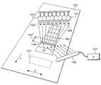
- FIG. 1is a schematic depiction of a multiple sensor, color measurement system in accordance with the present invention.
- FIG. 2is an exemplary ink-jet printer in which the present invention may be employed.
- FIG. 1is a schematic representation of a color measurement system in accordance with the present invention.
- Ink-jet printing technologyis used as an exemplary embodiment.
- the art of ink-jet technologyis relatively well developed.
- Commercial productssuch as computer printers, graphics plotters, copiers, facsimile machines, multifunctional peripheral (“MFP”) hard copy apparatus employ ink-jet technology for producing hard copy.
- MFPmultifunctional peripheral
- the basics of this technologyare disclosed in various articles in the Hewlett - Packard Journal , for example, Vol. 36, No. 5 (May 1985), Vol. 39, No. 4 (August 1988), Vol. 39, No. 5 (October 1988), Vol. 43, No. 4 (August 1992), Vol. 43, No. 6 (December 1992, and Vol. 45, No. 1 (February 1994) editions.
- Ink-Jet devicesare also describe by W. L. Lloyd and H. T. Taub in Output Hardcopy Devices , chapter 13 (Ed. R. C. Durbeck and S. Sherr, Academic Press, San Diego, 1988).
- a typical exemplary printer 200 in which the present invention may be employedis illustrated by FIG. 2 .
- the inventionuses a fixed array 101 of multiple sensors for observing neighboring positions of relatively long, intended uniform color, strips (e.g., 102 ′) of a test pattern 102 .
- the pattern 102has a plurality of such strips printed on a test sheet of print medium 103 by the hard copy apparatus (not shown) into which the present invention is implemented.
- the hard copy apparatusnot shown
- full color, scanning ink-jet printheadscreate a swath approximately an inch high in the media transport axis (see arrow labeled “Y”).
- Test bands approximately five inches long in the scanning axisare preferred.
- Similar test bands of colors of interestcan be generated with pens, laser-toner, thermal, or other color hard copy apparatus printing engines or individual writing instruments.
- the array 101is mounted downstream from the printing engine, thus taking advantage of the media transport devices inherent to the hard copy apparatus. By placing the array 101 in the paper path, multiple test bands 102 of color can be sequentially examined without any mechanical effort by the array.
- a single illumination source 105spectrally broad band—such as a halogen or xenon fluorescent lamp having an appropriate power supply 107 —projects incident light (represented by arrows) onto the test pattern 102 .
- a xenon lamphas the advantage of providing enough optical energy at short wavelengths to excite the fluorescence of paper brighteners, thus providing a more realistic measure of visually perceived color.
- Spectral information from the illuminated patternis analyzed in any known manner data processing technique as would be specifically advantageous for a particular implementation.
- spectral informationcan be determined by using different color LED's for each of the sensors (if desired in some implementations) or by using different filters (of various spectral characteristics) in front of the detectors and a single spectrally broadband illumination source such as a halogen or fluorescent lamp.
- the detectorscan be discrete photodetectors or elements of a photodetector array.
- the array 101is appropriately mounted in the X-axis parallel to the test band orientation on the print medium 103 .
- Individual sensors 104 of the arraycan be discrete photodetectors, each having an optical filter 106 of particular, narrow, spectral characteristics. Such photodetectors are commercially available from the Texas Advanced Optoelectronics Solutions company of Plano, Tex. Note that the individual sensors 104 can be discrete elements of a pre-manufactured array.
- Each sensor 104has a focusing lens 108 for a discrete area 109 , 111 (et seq. as shown in FIG. 1 ) of the test band 102 within the field of view of the array (the field of view is represented by diverging lines between each filter 106 and a spot representing the respective discrete area 109 of view for each sensor 104 .
- each individual sensor 104 of the array 101can be an LED and photodetector pair with different LED color devices.
- LEDsare commercially available from the Agilent Technologies company of Palo Alto, Calif.
- the printing engineis used to print a test pattern 102 of uniform strips 102 ′, each of an intended predetermined color, for example, a cyan strip, a magenta strip, a yellow strip, a red strip, a blue strip and a green strip, each having various chroma levels. All of the colors have intended color characteristics which can be stored in a look-up table (LUT) type memory.
- LUTlook-up table
- the first stripenters the field of view of the array 101 .
- Information generated by the array 101can then be stored in a conventional memory and used for comparison to the appropriate corresponding data in the LUT. Correction factors are generated for use by the printing engine in rendering images.
- a refinement of the present inventionuses a white calibration target 110 in the normal field of view of the array 101 and then a sheet of the print media is interposed between the array 101 and the target as it is moved from input to output. Without the sheet interposed, a sensor black level with the light source 105 off and white level calibration can be performed with the light source on. Color strip measurements can be offset and scaled appropriately between the black and white levels.
- the present inventionis easily scaled to fewer or greater numbers of spectral sensing bands depending on accuracy design goals and specifications.
Landscapes
- Physics & Mathematics (AREA)
- Spectroscopy & Molecular Physics (AREA)
- General Physics & Mathematics (AREA)
- Engineering & Computer Science (AREA)
- Multimedia (AREA)
- Signal Processing (AREA)
- Ink Jet (AREA)
- Accessory Devices And Overall Control Thereof (AREA)
- Spectrometry And Color Measurement (AREA)
Abstract
Description
Claims (15)
Priority Applications (1)
| Application Number | Priority Date | Filing Date | Title |
|---|---|---|---|
| US09/768,662US7227673B2 (en) | 2001-01-23 | 2001-01-23 | Color measurement with distributed sensors in a color hard copy apparatus |
Applications Claiming Priority (1)
| Application Number | Priority Date | Filing Date | Title |
|---|---|---|---|
| US09/768,662US7227673B2 (en) | 2001-01-23 | 2001-01-23 | Color measurement with distributed sensors in a color hard copy apparatus |
Publications (2)
| Publication Number | Publication Date |
|---|---|
| US20020097454A1 US20020097454A1 (en) | 2002-07-25 |
| US7227673B2true US7227673B2 (en) | 2007-06-05 |
Family
ID=25083136
Family Applications (1)
| Application Number | Title | Priority Date | Filing Date |
|---|---|---|---|
| US09/768,662Expired - LifetimeUS7227673B2 (en) | 2001-01-23 | 2001-01-23 | Color measurement with distributed sensors in a color hard copy apparatus |
Country Status (1)
| Country | Link |
|---|---|
| US (1) | US7227673B2 (en) |
Cited By (1)
| Publication number | Priority date | Publication date | Assignee | Title |
|---|---|---|---|---|
| US20130136349A1 (en)* | 2010-01-19 | 2013-05-30 | Akzo Nobel Coatings International B.V. | Method and system for determining colour from an image |
Families Citing this family (2)
| Publication number | Priority date | Publication date | Assignee | Title |
|---|---|---|---|---|
| JP2004170217A (en)* | 2002-11-19 | 2004-06-17 | Hamamatsu Photonics Kk | Coloration measuring apparatus |
| EP1761037A1 (en)* | 2005-09-02 | 2007-03-07 | Thomson Licensing | Colour chart and method for obtaining colour calibration values |
Citations (13)
| Publication number | Priority date | Publication date | Assignee | Title |
|---|---|---|---|---|
| US4003660A (en)* | 1975-12-03 | 1977-01-18 | Hunter Associates Laboratory, Inc. | Sensing head assembly for multi-color printing press on-line densitometer |
| US5107332A (en) | 1989-05-17 | 1992-04-21 | Hewlett-Packard Company | Method and system for providing closed loop color control between a scanned color image and the output of a color printer |
| US5508826A (en)* | 1993-04-27 | 1996-04-16 | Lloyd; William J. | Method and apparatus for calibrated digital printing using a four by four transformation matrix |
| US5671059A (en) | 1995-09-21 | 1997-09-23 | Hewlett-Packard Company | Electroluminescent color device |
| US5844663A (en) | 1996-09-13 | 1998-12-01 | Electronic Systems Engineering Co. | Method and apparatus for sequential exposure printing of ultra high resolution digital images using multiple multiple sub-image generation and a programmable moving-matrix light valve |
| US5914744A (en) | 1997-04-11 | 1999-06-22 | Eastman Kodak Company | Apparatus and method of printing with non-uniformity correction of exposure parameters to reduce low spatial frequency printed artifacts |
| US5929999A (en) | 1998-09-01 | 1999-07-27 | Hewlett-Packard Company | Light source for tristimulus colorimetry |
| US6002498A (en) | 1994-06-15 | 1999-12-14 | Konica Corporation | Image processing method and image forming method |
| US6036298A (en) | 1997-06-30 | 2000-03-14 | Hewlett-Packard Company | Monochromatic optical sensing system for inkjet printing |
| US6042213A (en) | 1994-10-28 | 2000-03-28 | Canon Kabushiki Kaisha | Method and apparatus for correcting printhead, printhead corrected by this apparatus, and printing apparatus using this printhead |
| US6061078A (en) | 1997-12-23 | 2000-05-09 | Eastman Kodak Company | Non-impact printer apparatus and method of printing with improved control of emitter pulsewidth modulation duration |
| US6069973A (en)* | 1998-06-30 | 2000-05-30 | Xerox Corporation | Method and apparatus for color correction in a multi-chip imaging array |
| US6384918B1 (en)* | 1999-11-24 | 2002-05-07 | Xerox Corporation | Spectrophotometer for color printer color control with displacement insensitive optics |
- 2001
- 2001-01-23USUS09/768,662patent/US7227673B2/ennot_activeExpired - Lifetime
Patent Citations (13)
| Publication number | Priority date | Publication date | Assignee | Title |
|---|---|---|---|---|
| US4003660A (en)* | 1975-12-03 | 1977-01-18 | Hunter Associates Laboratory, Inc. | Sensing head assembly for multi-color printing press on-line densitometer |
| US5107332A (en) | 1989-05-17 | 1992-04-21 | Hewlett-Packard Company | Method and system for providing closed loop color control between a scanned color image and the output of a color printer |
| US5508826A (en)* | 1993-04-27 | 1996-04-16 | Lloyd; William J. | Method and apparatus for calibrated digital printing using a four by four transformation matrix |
| US6002498A (en) | 1994-06-15 | 1999-12-14 | Konica Corporation | Image processing method and image forming method |
| US6042213A (en) | 1994-10-28 | 2000-03-28 | Canon Kabushiki Kaisha | Method and apparatus for correcting printhead, printhead corrected by this apparatus, and printing apparatus using this printhead |
| US5671059A (en) | 1995-09-21 | 1997-09-23 | Hewlett-Packard Company | Electroluminescent color device |
| US5844663A (en) | 1996-09-13 | 1998-12-01 | Electronic Systems Engineering Co. | Method and apparatus for sequential exposure printing of ultra high resolution digital images using multiple multiple sub-image generation and a programmable moving-matrix light valve |
| US5914744A (en) | 1997-04-11 | 1999-06-22 | Eastman Kodak Company | Apparatus and method of printing with non-uniformity correction of exposure parameters to reduce low spatial frequency printed artifacts |
| US6036298A (en) | 1997-06-30 | 2000-03-14 | Hewlett-Packard Company | Monochromatic optical sensing system for inkjet printing |
| US6061078A (en) | 1997-12-23 | 2000-05-09 | Eastman Kodak Company | Non-impact printer apparatus and method of printing with improved control of emitter pulsewidth modulation duration |
| US6069973A (en)* | 1998-06-30 | 2000-05-30 | Xerox Corporation | Method and apparatus for color correction in a multi-chip imaging array |
| US5929999A (en) | 1998-09-01 | 1999-07-27 | Hewlett-Packard Company | Light source for tristimulus colorimetry |
| US6384918B1 (en)* | 1999-11-24 | 2002-05-07 | Xerox Corporation | Spectrophotometer for color printer color control with displacement insensitive optics |
Cited By (2)
| Publication number | Priority date | Publication date | Assignee | Title |
|---|---|---|---|---|
| US20130136349A1 (en)* | 2010-01-19 | 2013-05-30 | Akzo Nobel Coatings International B.V. | Method and system for determining colour from an image |
| US8885934B2 (en)* | 2010-01-19 | 2014-11-11 | Akzo Nobel Coatings International B.V. | Method and system for determining colour from an image |
Also Published As
| Publication number | Publication date |
|---|---|
| US20020097454A1 (en) | 2002-07-25 |
Similar Documents
| Publication | Publication Date | Title |
|---|---|---|
| US8203749B2 (en) | Printing device, carriage and color measurement method | |
| US7773222B2 (en) | UV enhanced full width array scanning spectrophotometer | |
| CN100554898C (en) | Full Width Array Scanning Spectrophotometer | |
| US7864320B2 (en) | Method to minimize instrument differences in color management functions | |
| EP1267217B1 (en) | Calibration of a multi color imaging system using a predicted color shift | |
| US6690471B2 (en) | Color imager bar based spectrophotometer for color printer color control system | |
| US6556300B2 (en) | Color imager bar based spectrophotometer photodetector optical orientation | |
| US6538770B1 (en) | Color printer color control system using dual mode banner color test sheets | |
| US6567170B2 (en) | Simultaneous plural colors analysis spectrophotometer | |
| US6351308B1 (en) | Color printer color control system with automatic spectrophotometer calibration system | |
| US6633382B2 (en) | Angular, azimuthal and displacement insensitive spectrophotometer for color printer color control systems | |
| US10564038B2 (en) | Spectral characteristic acquiring apparatus, image forming apparatus, image forming system, image forming apparatus management system, and image forming apparatus management method | |
| US7961322B2 (en) | Method for conditional application of color measurement error compensation in spectral sensors | |
| US7760397B2 (en) | Calibration sheet and method of calibrating a digital printer | |
| EP1946267A1 (en) | Imaging methods, imaging device calibration methods, imaging devices, and hard imaging device sensor assemblies | |
| EP2340467A1 (en) | Imaging device calibration system and method | |
| US8004680B2 (en) | Color sensor performance | |
| US7034942B2 (en) | Color measurement device and color measurement method | |
| EP1260878B1 (en) | Simultaneous plural colors analysis spectrophotometer | |
| US7227673B2 (en) | Color measurement with distributed sensors in a color hard copy apparatus | |
| US8253996B2 (en) | System, color image producing device, color measurement device and color measurement method | |
| JP2016203472A (en) | Recording device and determination method | |
| JP2003035599A (en) | Color correction system based on color image forming bar used for color control system in color printer and spectrophotometer |
Legal Events
| Date | Code | Title | Description |
|---|---|---|---|
| AS | Assignment | Owner name:HEWLETT-PACKARD COMPANY, COLORADO Free format text:ASSIGNMENT OF ASSIGNORS INTEREST;ASSIGNOR:GUDAITIS, ALGIRD M.;REEL/FRAME:011797/0477 Effective date:20010119 | |
| AS | Assignment | Owner name:HEWLETT-PACKARD DEVELOPMENT COMPANY L.P., TEXAS Free format text:ASSIGNMENT OF ASSIGNORS INTEREST;ASSIGNOR:HEWLETT-PACKARD COMPANY;REEL/FRAME:014061/0492 Effective date:20030926 Owner name:HEWLETT-PACKARD DEVELOPMENT COMPANY L.P.,TEXAS Free format text:ASSIGNMENT OF ASSIGNORS INTEREST;ASSIGNOR:HEWLETT-PACKARD COMPANY;REEL/FRAME:014061/0492 Effective date:20030926 | |
| STCF | Information on status: patent grant | Free format text:PATENTED CASE | |
| CC | Certificate of correction | ||
| FPAY | Fee payment | Year of fee payment:4 | |
| FPAY | Fee payment | Year of fee payment:8 | |
| SULP | Surcharge for late payment | Year of fee payment:7 | |
| MAFP | Maintenance fee payment | Free format text:PAYMENT OF MAINTENANCE FEE, 12TH YEAR, LARGE ENTITY (ORIGINAL EVENT CODE: M1553) Year of fee payment:12 |