US7226047B1 - Welder's pipe clamp - Google Patents
Welder's pipe clampDownload PDFInfo
- Publication number
- US7226047B1 US7226047B1US11/245,785US24578505AUS7226047B1US 7226047 B1US7226047 B1US 7226047B1US 24578505 AUS24578505 AUS 24578505AUS 7226047 B1US7226047 B1US 7226047B1
- Authority
- US
- United States
- Prior art keywords
- pipe
- jaw
- clamp
- members
- sections
- Prior art date
- Legal status (The legal status is an assumption and is not a legal conclusion. Google has not performed a legal analysis and makes no representation as to the accuracy of the status listed.)
- Expired - Lifetime
Links
Images


Classifications
- B—PERFORMING OPERATIONS; TRANSPORTING
- B25—HAND TOOLS; PORTABLE POWER-DRIVEN TOOLS; MANIPULATORS
- B25B—TOOLS OR BENCH DEVICES NOT OTHERWISE PROVIDED FOR, FOR FASTENING, CONNECTING, DISENGAGING OR HOLDING
- B25B7/00—Pliers; Other hand-held gripping tools with jaws on pivoted limbs; Details applicable generally to pivoted-limb hand tools
- B25B7/02—Jaws
- B—PERFORMING OPERATIONS; TRANSPORTING
- B23—MACHINE TOOLS; METAL-WORKING NOT OTHERWISE PROVIDED FOR
- B23K—SOLDERING OR UNSOLDERING; WELDING; CLADDING OR PLATING BY SOLDERING OR WELDING; CUTTING BY APPLYING HEAT LOCALLY, e.g. FLAME CUTTING; WORKING BY LASER BEAM
- B23K37/00—Auxiliary devices or processes, not specially adapted for a procedure covered by only one of the other main groups of this subclass
- B23K37/04—Auxiliary devices or processes, not specially adapted for a procedure covered by only one of the other main groups of this subclass for holding or positioning work
- B23K37/053—Auxiliary devices or processes, not specially adapted for a procedure covered by only one of the other main groups of this subclass for holding or positioning work aligning cylindrical work; Clamping devices therefor
- B23K37/0533—External pipe alignment clamps
- B—PERFORMING OPERATIONS; TRANSPORTING
- B25—HAND TOOLS; PORTABLE POWER-DRIVEN TOOLS; MANIPULATORS
- B25B—TOOLS OR BENCH DEVICES NOT OTHERWISE PROVIDED FOR, FOR FASTENING, CONNECTING, DISENGAGING OR HOLDING
- B25B7/00—Pliers; Other hand-held gripping tools with jaws on pivoted limbs; Details applicable generally to pivoted-limb hand tools
- B25B7/02—Jaws
- B25B7/04—Jaws adjustable
- B—PERFORMING OPERATIONS; TRANSPORTING
- B23—MACHINE TOOLS; METAL-WORKING NOT OTHERWISE PROVIDED FOR
- B23K—SOLDERING OR UNSOLDERING; WELDING; CLADDING OR PLATING BY SOLDERING OR WELDING; CUTTING BY APPLYING HEAT LOCALLY, e.g. FLAME CUTTING; WORKING BY LASER BEAM
- B23K2101/00—Articles made by soldering, welding or cutting
- B23K2101/04—Tubular or hollow articles
- B23K2101/06—Tubes
- Y—GENERAL TAGGING OF NEW TECHNOLOGICAL DEVELOPMENTS; GENERAL TAGGING OF CROSS-SECTIONAL TECHNOLOGIES SPANNING OVER SEVERAL SECTIONS OF THE IPC; TECHNICAL SUBJECTS COVERED BY FORMER USPC CROSS-REFERENCE ART COLLECTIONS [XRACs] AND DIGESTS
- Y10—TECHNICAL SUBJECTS COVERED BY FORMER USPC
- Y10T—TECHNICAL SUBJECTS COVERED BY FORMER US CLASSIFICATION
- Y10T29/00—Metal working
- Y10T29/53—Means to assemble or disassemble
- Y10T29/53909—Means comprising hand manipulatable tool
- Y10T29/53913—Aligner or center
- Y10T29/53917—Tube with tube
Definitions
- the present inventionrelates to a tool for holding two pipe sections in proper alignment for a welder.
- U.S. Pat. No. 4,601,221 issued to Kalkbrenner, et al.discloses a clamping device for rectangular work pieces including a pair of right angled jaw portions that form rectangular openings to hold a rectangular work piece.
- U.S. Pat. No. 4,603,174 issued to Tabbertdiscloses an angled clamping tool that is designed to retain work pieces at a selected angular relationship.
- U.S. Pat. No. 6,389,937 issued to Kangdiscloses universal pliers for removing and installing varying diameter pipes.
- each of the above described devicesis designed to assist a worker with fastening a pipe section to a pipe fitting.
- none of the prior art devicesare specifically designed to hold two pipe sections in fixed, coaxial alignment while a worker welds the two sections together.
- the present inventionprovides a uniquely designed clamp that includes a pair of arcuate, pipe clamping surfaces that simultaneously encompass a pair of pipe sections while a worker tack welds the joint formed therebetween.
- the present inventionrelates to a welder's pipe clamp including a pair of reciprocal handle members each having a pivotal jaw attached thereto.
- Each jawincludes a pipe clamping member pivotally attached to a distal end thereof.
- Each pipe clamping memberincludes upper and lower arcuate, pipe-engaging surfaces that maintain a pair of pipe sections in alignment for a welder.
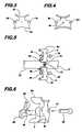
- FIG. 1is a side view of the pipe clamping tool according to the present invention.
- FIG. 2is an isometric view of a clamping member.
- FIG. 3is a front view of a clamping member.
- FIG. 4is a rear view of a clamping member.
- FIG. 5is a perspective view of the tool according to the present invention secured about a pair of aligned pipe sections.
- FIG. 6depicts the means of attaching each clamping member to a corresponding jaw.
- the present inventionrelates to a welder's pipe clamp.
- the devicecomprises an upper jaw 4 a and a lower jaw 4 b each terminating at a distal end. Both the upper jaw and the lower jaw are pivotally secured to a distal end of an upper handle member 2 .
- the lower jawis likewise pivotally attached to an end of a lower handle member 12 .
- the upper and lower handle membersare pivotally interconnected by a brace member 13 that allows the handle members to be reciprocated to move the jaws toward and away from each other.
- the lower handle memberincludes a compression screw 2 a that threadedly rides therein for adjusting the tension on the upper jaw.
- a spring 10opens the upper jaw when a release lever 14 is depressed and also maintains pressure on an internal locking mechanism to maintain the upper and lower jaws in a locked relationship about an object.
- the above described handle locking mechanismis conventional and is similar to that found in traditional locking pliers.
- Each pipe clamp memberincludes an upper 6 a , 8 b and a lower 6 b , 8 a arcuate pipe engaging surface for partially encompassing a portion of a pipe circumference.
- the upper clamp pipe engaging surfacehas a different curvature than that of the lower clamping surface so that the two clamp members can be removed and inverted to fit about a pipe having a different sized diameter.
- each clamp memberis secured to its respective jaw with a detent type locking pin 20 that seats within a bore 21 on the clamping member and a coaxial passageway 22 on the corresponding jaw.
- the diameters of the bore and passagewayare slightly larger than that of the pin to allow each clamping member to move slightly relative to the jaws when being clamped about a pipe exterior.
- Each jawfurther includes a nipple 24 that seats within a channel 6 e , 8 e formed on each clamping member.
- a workerassures that the appropriately sized pipe engaging surfaces are facing each other depending upon the size of the pipes to be welded.
- the workerfirst attempts to clamp the tool about a first pipe section 16 to assure that the jaws are properly spaced to allow tight fastening about the pipe sections.
- the compression screwis adjusted if necessary to achieve the desired jaw spacing.
- An end of the first pipe sectionis placed between the two clamping members and the handles are compressed sufficiently to hold the pipe section in place.
- the other pipe section 17is likewise placed between the clamping members and the two pipes are aligned as desired. Once the pipe sections are properly aligned, the handles are locked allowing the worker to tack weld the resulting joint 18 between the two pipe sections. By actuating the release lever, the worker can remove the clamp and finish welding the joint.
- the above described deviceis not limited to the exact details of construction and enumeration of parts provided herein. Furthermore, the size, shape, materials of construction as well as the size and number of clamping members can be varied.
Landscapes
- Engineering & Computer Science (AREA)
- Mechanical Engineering (AREA)
- Physics & Mathematics (AREA)
- Optics & Photonics (AREA)
- Gripping Jigs, Holding Jigs, And Positioning Jigs (AREA)
Abstract
Description
Claims (3)
Priority Applications (1)
| Application Number | Priority Date | Filing Date | Title |
|---|---|---|---|
| US11/245,785US7226047B1 (en) | 2004-09-02 | 2005-09-02 | Welder's pipe clamp |
Applications Claiming Priority (2)
| Application Number | Priority Date | Filing Date | Title |
|---|---|---|---|
| US60674804P | 2004-09-02 | 2004-09-02 | |
| US11/245,785US7226047B1 (en) | 2004-09-02 | 2005-09-02 | Welder's pipe clamp |
Publications (1)
| Publication Number | Publication Date |
|---|---|
| US7226047B1true US7226047B1 (en) | 2007-06-05 |
Family
ID=38090067
Family Applications (1)
| Application Number | Title | Priority Date | Filing Date |
|---|---|---|---|
| US11/245,785Expired - LifetimeUS7226047B1 (en) | 2004-09-02 | 2005-09-02 | Welder's pipe clamp |
Country Status (1)
| Country | Link |
|---|---|
| US (1) | US7226047B1 (en) |
Cited By (15)
| Publication number | Priority date | Publication date | Assignee | Title |
|---|---|---|---|---|
| US20160096283A1 (en)* | 2014-04-16 | 2016-04-07 | Lindsay Engraving, Inc. | Reversible Coin Holder |
| WO2016175902A1 (en)* | 2015-04-30 | 2016-11-03 | Hubbell Incorporated | Modular area luminaire |
| US20160361822A1 (en)* | 2013-02-28 | 2016-12-15 | Booker & Dax, Llc | Torch and torch attachment |
| US9938123B1 (en)* | 2013-03-14 | 2018-04-10 | Nick C. Kravitch | Valve box lifter |
| CN108436337A (en)* | 2018-04-23 | 2018-08-24 | 格力电器(武汉)有限公司 | Be applied to nitrogen frock of filling of air conditioner stop valve |
| US20190186219A1 (en)* | 2017-12-19 | 2019-06-20 | Falcon Tools, LLC | Moveable jaw bit breaker technology |
| CN110960820A (en)* | 2019-12-12 | 2020-04-07 | 江苏深渡消防装备科技有限公司 | Proportional mixer for foam fire extinguishing system |
| US10676037B2 (en)* | 2015-09-22 | 2020-06-09 | Grip Racks LLC | Modular roof rack clamping system |
| US20200198098A1 (en)* | 2018-12-20 | 2020-06-25 | Toyota Motor Engineering & Manufacturing North America, Inc. | Split Vise |
| CN112628579A (en)* | 2019-10-09 | 2021-04-09 | 和硕联合科技股份有限公司 | Clamping device |
| US11391101B2 (en) | 2017-12-19 | 2022-07-19 | Falcon Tools, LLC | Bit breaker technology |
| US20230009578A1 (en)* | 2020-01-27 | 2023-01-12 | Laitram, L.L.C. | Hinge-rod removal and insertion tool |
| DE102021120815A1 (en) | 2021-08-10 | 2023-02-16 | OWT GmbH & Co. KG | METHOD AND SELF-CENTERING FIXING DEVICE FOR FIXING A WELDING DEVICE TO A SECTION OF PIPE |
| US11612969B1 (en) | 2021-11-30 | 2023-03-28 | John Arsenault, Jr. | Pipe welding stabilizer |
| USD1026591S1 (en)* | 2022-04-05 | 2024-05-14 | Harry Wong | Pipe joining pliers |
Citations (7)
| Publication number | Priority date | Publication date | Assignee | Title |
|---|---|---|---|---|
| US1531377A (en)* | 1922-10-28 | 1925-03-31 | Clement S Clarke | Pipe tongs |
| US4306345A (en) | 1979-09-21 | 1981-12-22 | Dearman Timothy Charles | Pipefitter's tool |
| US4344215A (en) | 1979-09-21 | 1982-08-17 | Dearman Timothy Charles | Pipefitter's tool |
| US4483059A (en)* | 1981-09-03 | 1984-11-20 | Dearman Timothy Charles | Clamping and spacing tool |
| US4601221A (en) | 1984-11-09 | 1986-07-22 | Westinghouse Electric Corp. | Clamping device for rectangular workpiece |
| US4673174A (en) | 1986-07-11 | 1987-06-16 | Tabbert William D | Angle clamping tool |
| US6389937B1 (en) | 2001-06-19 | 2002-05-21 | Hsin-Fa Kang | Universal grip pliers |
- 2005
- 2005-09-02USUS11/245,785patent/US7226047B1/ennot_activeExpired - Lifetime
Patent Citations (7)
| Publication number | Priority date | Publication date | Assignee | Title |
|---|---|---|---|---|
| US1531377A (en)* | 1922-10-28 | 1925-03-31 | Clement S Clarke | Pipe tongs |
| US4306345A (en) | 1979-09-21 | 1981-12-22 | Dearman Timothy Charles | Pipefitter's tool |
| US4344215A (en) | 1979-09-21 | 1982-08-17 | Dearman Timothy Charles | Pipefitter's tool |
| US4483059A (en)* | 1981-09-03 | 1984-11-20 | Dearman Timothy Charles | Clamping and spacing tool |
| US4601221A (en) | 1984-11-09 | 1986-07-22 | Westinghouse Electric Corp. | Clamping device for rectangular workpiece |
| US4673174A (en) | 1986-07-11 | 1987-06-16 | Tabbert William D | Angle clamping tool |
| US6389937B1 (en) | 2001-06-19 | 2002-05-21 | Hsin-Fa Kang | Universal grip pliers |
Cited By (25)
| Publication number | Priority date | Publication date | Assignee | Title |
|---|---|---|---|---|
| US10105851B2 (en)* | 2013-02-28 | 2018-10-23 | Booker & Dax Llc | Torch and torch attachment |
| US20160361822A1 (en)* | 2013-02-28 | 2016-12-15 | Booker & Dax, Llc | Torch and torch attachment |
| US9938123B1 (en)* | 2013-03-14 | 2018-04-10 | Nick C. Kravitch | Valve box lifter |
| US10221057B1 (en)* | 2013-03-14 | 2019-03-05 | Nick C. Kravitch | Method and apparatus for removing a cover from a valve box |
| US20160096283A1 (en)* | 2014-04-16 | 2016-04-07 | Lindsay Engraving, Inc. | Reversible Coin Holder |
| US9448537B2 (en)* | 2014-04-16 | 2016-09-20 | Steven J Lindsay | Reversible coin holder |
| US9777911B2 (en) | 2015-04-30 | 2017-10-03 | Hubbell Incorporated | Modular area luminaire |
| AU2015393124B2 (en)* | 2015-04-30 | 2021-06-03 | Hubbell Lighting, Inc. | Modular area luminaire |
| WO2016175902A1 (en)* | 2015-04-30 | 2016-11-03 | Hubbell Incorporated | Modular area luminaire |
| US10676037B2 (en)* | 2015-09-22 | 2020-06-09 | Grip Racks LLC | Modular roof rack clamping system |
| US20190186219A1 (en)* | 2017-12-19 | 2019-06-20 | Falcon Tools, LLC | Moveable jaw bit breaker technology |
| US10428604B2 (en)* | 2017-12-19 | 2019-10-01 | Falcon Tools, LLC | Moveable jaw bit breaker technology |
| US11391101B2 (en) | 2017-12-19 | 2022-07-19 | Falcon Tools, LLC | Bit breaker technology |
| US11085254B2 (en) | 2017-12-19 | 2021-08-10 | Falcon Tools, LLC | Bit breaker technology |
| CN108436337A (en)* | 2018-04-23 | 2018-08-24 | 格力电器(武汉)有限公司 | Be applied to nitrogen frock of filling of air conditioner stop valve |
| US10864615B2 (en)* | 2018-12-20 | 2020-12-15 | Toyota Motor Engineering & Manufacturing North America, Inc. | Split vise |
| US20200198098A1 (en)* | 2018-12-20 | 2020-06-25 | Toyota Motor Engineering & Manufacturing North America, Inc. | Split Vise |
| CN112628579A (en)* | 2019-10-09 | 2021-04-09 | 和硕联合科技股份有限公司 | Clamping device |
| US11359653B2 (en)* | 2019-10-09 | 2022-06-14 | Pegatron Corporation | Clamping device |
| CN110960820A (en)* | 2019-12-12 | 2020-04-07 | 江苏深渡消防装备科技有限公司 | Proportional mixer for foam fire extinguishing system |
| US20230009578A1 (en)* | 2020-01-27 | 2023-01-12 | Laitram, L.L.C. | Hinge-rod removal and insertion tool |
| US12337448B2 (en)* | 2020-01-27 | 2025-06-24 | Laitram, L.L.C. | Hinge-rod removal and insertion tool |
| DE102021120815A1 (en) | 2021-08-10 | 2023-02-16 | OWT GmbH & Co. KG | METHOD AND SELF-CENTERING FIXING DEVICE FOR FIXING A WELDING DEVICE TO A SECTION OF PIPE |
| US11612969B1 (en) | 2021-11-30 | 2023-03-28 | John Arsenault, Jr. | Pipe welding stabilizer |
| USD1026591S1 (en)* | 2022-04-05 | 2024-05-14 | Harry Wong | Pipe joining pliers |
Similar Documents
| Publication | Publication Date | Title |
|---|---|---|
| US7226047B1 (en) | Welder's pipe clamp | |
| US6431534B1 (en) | Clamping tool for aligning tubes | |
| US7104166B1 (en) | Multi-purpose locking plier | |
| EP3119557B1 (en) | Socket fusion jig for pipes | |
| US4673174A (en) | Angle clamping tool | |
| US4834352A (en) | Clamp | |
| US8789821B2 (en) | Tab welding bracket | |
| TW201330992A (en) | Tool for coupling fluid lines | |
| US7954356B1 (en) | PEX crimping tool | |
| WO2009015428A1 (en) | Clamp | |
| US20170021474A1 (en) | Tube Clamping Hand Tool | |
| US5007312A (en) | Wrench for metal tubing connectors | |
| US20030233914A1 (en) | Pliers for clamping a hose or tube | |
| US8348253B2 (en) | Modified boiler wall tube tool | |
| US20050173853A1 (en) | Portable vise | |
| AU752806B2 (en) | Sheet metal repair method, sheet metal repair tool, and sheet-like member fixing device | |
| CA2490701C (en) | Method and tool for aligning piping components | |
| US20060060037A1 (en) | Hand-held-wrench stand and stabilizer | |
| CN214723870U (en) | Disassembling and assembling pliers | |
| US6776403B1 (en) | Hand tool for portably holding workpieces during drilling or grinding operations | |
| US8096536B2 (en) | Alignment tool for use in soldering roughed-in service pipes | |
| US20060214342A1 (en) | Apparatus and method for holding in position adjacent facing ends of tube sections for joining them by welding | |
| US20050061118A1 (en) | 90 angle clamping pliers | |
| US2703502A (en) | Crossed handle wrench with adjustable fulcrum | |
| US4306592A (en) | Method of and tool for use in applying soft wire clamps to flexible tubing |
Legal Events
| Date | Code | Title | Description |
|---|---|---|---|
| STCF | Information on status: patent grant | Free format text:PATENTED CASE | |
| FPAY | Fee payment | Year of fee payment:4 | |
| FEPP | Fee payment procedure | Free format text:PATENT HOLDER CLAIMS MICRO ENTITY STATUS, ENTITY STATUS SET TO MICRO (ORIGINAL EVENT CODE: STOM); ENTITY STATUS OF PATENT OWNER: SMALL ENTITY | |
| REMI | Maintenance fee reminder mailed | ||
| FPAY | Fee payment | Year of fee payment:8 | |
| SULP | Surcharge for late payment | ||
| AS | Assignment | Owner name:BEAUCHAMP, GRACE, LOUISIANA Free format text:COURT ORDER;ASSIGNOR:BEAUCHAMP, ABEL;REEL/FRAME:044527/0076 Effective date:20170331 Owner name:SAWYER MANUFACTURING COMPANY, OKLAHOMA Free format text:ASSIGNMENT OF ASSIGNORS INTEREST;ASSIGNOR:BEAUCHAMP, GRACE;REEL/FRAME:044527/0158 Effective date:20171212 | |
| FEPP | Fee payment procedure | Free format text:MAINTENANCE FEE REMINDER MAILED (ORIGINAL EVENT CODE: REM.); ENTITY STATUS OF PATENT OWNER: MICROENTITY | |
| FEPP | Fee payment procedure | Free format text:ENTITY STATUS SET TO SMALL (ORIGINAL EVENT CODE: SMAL); ENTITY STATUS OF PATENT OWNER: SMALL ENTITY Free format text:11.5 YR SURCHARGE- LATE PMT W/IN 6 MO, SMALL ENTITY (ORIGINAL EVENT CODE: M2556); ENTITY STATUS OF PATENT OWNER: SMALL ENTITY | |
| MAFP | Maintenance fee payment | Free format text:PAYMENT OF MAINTENANCE FEE, 12TH YR, SMALL ENTITY (ORIGINAL EVENT CODE: M2553); ENTITY STATUS OF PATENT OWNER: SMALL ENTITY Year of fee payment:12 |