US7224769B2 - Digital x-ray camera - Google Patents
Digital x-ray cameraDownload PDFInfo
- Publication number
- US7224769B2 US7224769B2US10/529,806US52980605AUS7224769B2US 7224769 B2US7224769 B2US 7224769B2US 52980605 AUS52980605 AUS 52980605AUS 7224769 B2US7224769 B2US 7224769B2
- Authority
- US
- United States
- Prior art keywords
- ray
- power
- housing
- integrated
- providing
- Prior art date
- Legal status (The legal status is an assumption and is not a legal conclusion. Google has not performed a legal analysis and makes no representation as to the accuracy of the status listed.)
- Expired - Lifetime
Links
- 239000011810insulating materialSubstances0.000claimsabstractdescription24
- 238000000034methodMethods0.000claimsabstractdescription16
- 239000000126substanceSubstances0.000claimsabstractdescription13
- 238000003384imaging methodMethods0.000claimsdescription18
- 238000004458analytical methodMethods0.000claimsdescription7
- 238000005516engineering processMethods0.000claimsdescription7
- 238000002441X-ray diffractionMethods0.000claimsdescription4
- 230000000474nursing effectEffects0.000abstractdescription2
- 239000000463materialSubstances0.000description18
- 230000005855radiationEffects0.000description9
- 238000006243chemical reactionMethods0.000description8
- 230000007246mechanismEffects0.000description8
- 238000013461designMethods0.000description7
- 239000003921oilSubstances0.000description7
- 239000010410layerSubstances0.000description5
- 229920002379silicone rubberPolymers0.000description5
- 238000007689inspectionMethods0.000description4
- 239000004945silicone rubberSubstances0.000description4
- 230000005540biological transmissionEffects0.000description3
- 230000006870functionEffects0.000description3
- 230000006872improvementEffects0.000description3
- 230000033001locomotionEffects0.000description3
- 238000012986modificationMethods0.000description3
- 230000004048modificationEffects0.000description3
- 238000003825pressingMethods0.000description3
- 238000003860storageMethods0.000description3
- 238000004876x-ray fluorescenceMethods0.000description3
- 238000010521absorption reactionMethods0.000description2
- 230000008901benefitEffects0.000description2
- 210000000988bone and boneAnatomy0.000description2
- 230000008859changeEffects0.000description2
- 238000001514detection methodMethods0.000description2
- 239000007788liquidSubstances0.000description2
- 239000004973liquid crystal related substanceSubstances0.000description2
- 239000002184metalSubstances0.000description2
- 229910052751metalInorganic materials0.000description2
- 229920001296polysiloxanePolymers0.000description2
- 230000008569processEffects0.000description2
- 239000004593EpoxySubstances0.000description1
- 229910005580NiCdInorganic materials0.000description1
- 230000001594aberrant effectEffects0.000description1
- NIXOWILDQLNWCW-UHFFFAOYSA-Nacrylic acid groupChemical groupC(C=C)(=O)ONIXOWILDQLNWCW-UHFFFAOYSA-N0.000description1
- 239000000956alloySubstances0.000description1
- 229910045601alloyInorganic materials0.000description1
- 238000003491arrayMethods0.000description1
- 229910052788bariumInorganic materials0.000description1
- 239000003086colorantSubstances0.000description1
- 150000001875compoundsChemical class0.000description1
- 238000000326densiometryMethods0.000description1
- 238000003745diagnosisMethods0.000description1
- 238000002059diagnostic imagingMethods0.000description1
- 239000002355dual-layerSubstances0.000description1
- 238000010894electron beam technologyMethods0.000description1
- 239000000499gelSubstances0.000description1
- 238000009499grossingMethods0.000description1
- 229910001385heavy metalInorganic materials0.000description1
- 238000010191image analysisMethods0.000description1
- 238000003707image sharpeningMethods0.000description1
- 238000007373indentationMethods0.000description1
- 230000000977initiatory effectEffects0.000description1
- 230000010354integrationEffects0.000description1
- 238000002955isolationMethods0.000description1
- 229910052745leadInorganic materials0.000description1
- 238000004519manufacturing processMethods0.000description1
- 238000005259measurementMethods0.000description1
- 239000012528membraneSubstances0.000description1
- 230000005055memory storageEffects0.000description1
- 239000013528metallic particleSubstances0.000description1
- 150000002739metalsChemical class0.000description1
- 238000002156mixingMethods0.000description1
- 239000004033plasticSubstances0.000description1
- 238000007747platingMethods0.000description1
- 238000004382pottingMethods0.000description1
- 230000009467reductionEffects0.000description1
- 239000002689soilSubstances0.000description1
- 239000011343solid materialSubstances0.000description1
- 238000012546transferMethods0.000description1
- 229910052721tungstenInorganic materials0.000description1
- 210000003954umbilical cordAnatomy0.000description1
- XLYOFNOQVPJJNP-UHFFFAOYSA-NwaterSubstancesOXLYOFNOQVPJJNP-UHFFFAOYSA-N0.000description1
Images


Classifications
- A—HUMAN NECESSITIES
- A61—MEDICAL OR VETERINARY SCIENCE; HYGIENE
- A61B—DIAGNOSIS; SURGERY; IDENTIFICATION
- A61B6/00—Apparatus or devices for radiation diagnosis; Apparatus or devices for radiation diagnosis combined with radiation therapy equipment
- A61B6/50—Apparatus or devices for radiation diagnosis; Apparatus or devices for radiation diagnosis combined with radiation therapy equipment specially adapted for specific body parts; specially adapted for specific clinical applications
- A61B6/505—Apparatus or devices for radiation diagnosis; Apparatus or devices for radiation diagnosis combined with radiation therapy equipment specially adapted for specific body parts; specially adapted for specific clinical applications for diagnosis of bone
- A—HUMAN NECESSITIES
- A61—MEDICAL OR VETERINARY SCIENCE; HYGIENE
- A61B—DIAGNOSIS; SURGERY; IDENTIFICATION
- A61B6/00—Apparatus or devices for radiation diagnosis; Apparatus or devices for radiation diagnosis combined with radiation therapy equipment
- A61B6/44—Constructional features of apparatus for radiation diagnosis
- A61B6/4411—Constructional features of apparatus for radiation diagnosis the apparatus being modular
- A—HUMAN NECESSITIES
- A61—MEDICAL OR VETERINARY SCIENCE; HYGIENE
- A61B—DIAGNOSIS; SURGERY; IDENTIFICATION
- A61B6/00—Apparatus or devices for radiation diagnosis; Apparatus or devices for radiation diagnosis combined with radiation therapy equipment
- A61B6/50—Apparatus or devices for radiation diagnosis; Apparatus or devices for radiation diagnosis combined with radiation therapy equipment specially adapted for specific body parts; specially adapted for specific clinical applications
- A61B6/51—Apparatus or devices for radiation diagnosis; Apparatus or devices for radiation diagnosis combined with radiation therapy equipment specially adapted for specific body parts; specially adapted for specific clinical applications for dentistry
- A—HUMAN NECESSITIES
- A61—MEDICAL OR VETERINARY SCIENCE; HYGIENE
- A61B—DIAGNOSIS; SURGERY; IDENTIFICATION
- A61B6/00—Apparatus or devices for radiation diagnosis; Apparatus or devices for radiation diagnosis combined with radiation therapy equipment
- A61B6/54—Control of apparatus or devices for radiation diagnosis
- A61B6/548—Remote control of the apparatus or devices
- G—PHYSICS
- G01—MEASURING; TESTING
- G01T—MEASUREMENT OF NUCLEAR OR X-RADIATION
- G01T7/00—Details of radiation-measuring instruments
- G—PHYSICS
- G01—MEASURING; TESTING
- G01V—GEOPHYSICS; GRAVITATIONAL MEASUREMENTS; DETECTING MASSES OR OBJECTS; TAGS
- G01V5/00—Prospecting or detecting by the use of ionising radiation, e.g. of natural or induced radioactivity
- G01V5/20—Detecting prohibited goods, e.g. weapons, explosives, hazardous substances, contraband or smuggled objects
- A—HUMAN NECESSITIES
- A61—MEDICAL OR VETERINARY SCIENCE; HYGIENE
- A61B—DIAGNOSIS; SURGERY; IDENTIFICATION
- A61B6/00—Apparatus or devices for radiation diagnosis; Apparatus or devices for radiation diagnosis combined with radiation therapy equipment
- A61B6/44—Constructional features of apparatus for radiation diagnosis
- A61B6/4405—Constructional features of apparatus for radiation diagnosis the apparatus being movable or portable, e.g. handheld or mounted on a trolley
- A—HUMAN NECESSITIES
- A61—MEDICAL OR VETERINARY SCIENCE; HYGIENE
- A61B—DIAGNOSIS; SURGERY; IDENTIFICATION
- A61B6/00—Apparatus or devices for radiation diagnosis; Apparatus or devices for radiation diagnosis combined with radiation therapy equipment
- A61B6/44—Constructional features of apparatus for radiation diagnosis
- A61B6/4488—Means for cooling
- A—HUMAN NECESSITIES
- A61—MEDICAL OR VETERINARY SCIENCE; HYGIENE
- A61B—DIAGNOSIS; SURGERY; IDENTIFICATION
- A61B6/00—Apparatus or devices for radiation diagnosis; Apparatus or devices for radiation diagnosis combined with radiation therapy equipment
- A61B6/50—Apparatus or devices for radiation diagnosis; Apparatus or devices for radiation diagnosis combined with radiation therapy equipment specially adapted for specific body parts; specially adapted for specific clinical applications
- A61B6/508—Apparatus or devices for radiation diagnosis; Apparatus or devices for radiation diagnosis combined with radiation therapy equipment specially adapted for specific body parts; specially adapted for specific clinical applications for non-human patients
Definitions
- the inventiongenerally relates to x-ray devices and methods for using the same. More particularly, the invention relates to portable x-ray devices that contain an unattached x-ray detector, methods for using such portable x-ray devices as a digital x-ray camera, and systems containing such portable x-ray devices.
- Typical x-ray tubes and x-ray deviceshave been known and used for some time. Unfortunately, they are usually bulky and are powered by heavy, high-voltage power supplies that restrict mobility. As well, they are often difficult and time-consuming to use. In many instances, a sample for analysis must be sent to an off-site laboratory for analysis by the x-ray device.
- a further limitation on design of the increased portabilityis the image display components.
- High-quality imaging displays for displaying the results of the x-ray analysisare difficult to integrate into the design of the housing of the portable x-ray device. Consequently, many of the portable designs have the image display component external to the chassis or housing containing the x-ray tube.
- the inventionrelates to portable x-ray devices and methods for using such devices.
- the x-ray deviceshave an x-ray tube powered by an integrated power system.
- the x-ray tubeis shielded with a low-density insulating material containing a high-Z substance.
- the x-ray devicescan also have an integrated display component. With these components, the size and weight of the x-ray devices can be reduced and the portability of the devices enhanced.
- the x-ray devicescan also have detecting means that is not structurally attached to the device and therefore is free standing. Consequently, the x-ray devices can also be used as a digital x-ray camera.
- the portable x-ray devicesare especially useful for applications where portability is an important feature such as in field work, remote operations, and mobile operations such as nursing homes, home healthcare, or teaching classrooms.
- This portability featurecan be particularly useful in multi-suite medical and dental offices where a single x-ray device can be used as a digital x-ray camera in multiple offices instead of requiring a separate device in every office.
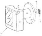
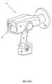
- FIGS. 1-2depict the x-ray device in one aspect of the invention
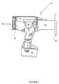
- FIG. 3depicts the x-ray device in another aspect of the invention.
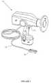
- FIG. 4depicts the x-ray device in another aspect of the invention.
- FIG. 5depicts the x-ray tube and power supply of the x-ray device in one aspect of the invention
- FIGS. 6-7depict the power source of the x-ray device and method for connecting the power source to the x-ray device in one aspect of the invention
- FIG. 8depicts the x-ray tube of the x-ray device in one aspect of the invention.
- FIG. 9depicts a conventional x-ray tube in a conventional configuration
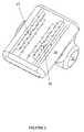
- FIGS. 10-12depicts the x-ray device in one aspect of the invention.
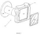
- FIGS. 13-17depicts the x-ray in another aspect of the invention.
- FIGS. 1-17illustrate specific aspects of the invention and are a part of the specification.
- the inventionincludes a portable x-ray device that is used primarily for remote and/or office applications, including in multi-suite office locations.
- the x-ray devicecan be designed to be either handheld or temporarily fixed to a given location, such as a tripod-mount operation.
- the inventioncould be mounted on any other semi-stable apparatus, such as an articulating arm or C-arm as commonly used in radiology applications and described in the publications mentioned above.
- the x-ray device of the inventionis portable in that it can be transported by hand carrying it from one location to a second location without support by any mechanical apparatus. Because it uses an integrated power system, the location of its use can be independent of any external fixed power source, such as utility-supplied AC voltage often required in the home or office. As well, the x-ray device contains detecting means that is not structurally attached to the device and therefore is free standing. This independence from an external power source and free-standing detecting means are particularly useful features of the x-ray devices of the invention.
- the x-ray device 10 of the inventioncontains a housing or chassis 20 to contain all the internal components of the device.
- the housing 20encloses an x-ray tube 30 for producing the x-rays.
- the x-ray device 10contains a power system (including power source 40 ) to provide power for the device 10 and means for detecting the x-rays, such as film, CCD sensors, or imaging plates (not shown).
- the x-ray device 10also contains means for displaying the results of the analysis such as an integrated image display screen 60 (shown in FIG. 4 ); control means such as controller 70 ; and radiation shielding 80 to shield the operator of the device from backscattered radiation from the sample.
- the x-ray device 10also contains any other components known in the art for efficient operation (such as x-ray collimator 32 ), including those components described in the documents mentioned above.
- the x-ray device 10contains a unique system for providing power to the x-ray device.
- the power system of the x-ray devicecomprises a power source 40 , power supply 34 , and conversion means.
- the power source 40 used in the x-ray device of the inventioncan be any known in the art that can supply the desired amount of power, yet fit within the space limitations of the x-ray device.
- the power sourcecomprises a battery, such as a 14.4V NiCd battery pack.
- the power sourcecan be recharged by any suitable means, such as by connection to an appropriate voltage when using batteries that are re-chargeable.
- the power source 40is removable from the remainder of the x-ray device 10 .
- the power source 40comprises mechanical and electrical means for connecting the power source 40 to the x-ray device 10 .
- the electrical and mechanical connection meanscan be any of those known in the art. As depicted in FIG. 6 , the electrical connection means can comprise an extension member 41 with an electrical connector 42 contained in an upper portion thereof.
- the mechanical connection meanscomprises a release mechanism 43 a.
- the x-ray device 10contains a locking mechanism 43 b .
- the power source 40is gently pushed into the bottom of the handle 15 of the x-ray device 10 .
- the electrical connector 42connects with the internal electronics of the x-ray device 10 .
- the locking mechanism 43 bis automatically engaged to retain the power source 40 connected to the x-ray device 10 in this position.
- the release mechanism 43 ais actuated to unlock the locking mechanism 43 b , and the power source 40 can be gently slid out from the handle 15 .
- the power source 40is electrically connected to the conversion means using any connection means known in the art, including those described in the publications above.
- the conversion meansconverts the initial voltage supplied by the power source 40 to a converted voltage that is provided to the power supply 34 .
- the conversion meansgenerally converts the 14.4V (or similar voltage) provided by the power source 40 to a voltage ranging from about 80 to about 200V. In one aspect of the invention, the initial voltage is converted to a converted voltage of about 100V. Any conversion means known in the art that operates in this manner can be used in the invention, including the power management boards 36 .
- the conversion meansis electrically connected to the power supply 34 .
- the power supply 34steps up the converted voltage (i.e., the 100V) provided by the conversion means to a voltage that can be used by the x-ray tube 30 .
- the power produced by the power supply 34 and input into the x-ray tube 30 via connection 35depends on the power needed to operate the x-ray tube, and the maximum power available from the power source.
- the power provided by the power supply 34 to the x-ray tube 30can range from about 20 to about 150 kV.
- this power provided by the power supplycan range from about 40 kV to about 100 kV.
- the power provided by the power supplyis provided by a plurality of individual power supplies.
- the number of individual power supplies useddepends on the voltage needed for the x-ray tube, the space needed for the power supply 34 , the total power available from the power source, and the number of electron-accelerating grids in the x-ray tube.
- the plurality of individual power suppliesis two (as represented in FIG. 5 by 45 , 46 ) where 45 supplies positive voltage to the anode and 46 supplies negative voltage to the cathode.
- the power provided by each individual power supplydepends on the number of individual power supplies used, the maximum power available from the power source, and the heat-dissipating capability of the x-ray tube. Generally, the power supplied by each individual power supply is the total power needed to operate the x-ray tube divided by the number of individual power supplies. For example, the power provided by each individual power supply (when there are 2) can range from about 20 kV to about 50 kV. In one aspect of the invention, the power provided by each individual power supply (when there are 2) is about +35 kV and ⁇ 35 kV.
- the +35 kVis attached to the anode of the x-ray tube and the ⁇ 35 kV is attached to the cathode of the x-ray tube.
- a filament transformeris included in the cathode power supply to provide current to the x-ray tube filament and generate an electron beam at the cathode of the tube. The total power produced by the power supply is therefore the sum of the individual anode power supply and the individual cathode power supply.
- the x-ray tube 30 of the inventionbecomes more portable.
- Conventional x-ray tubesoperate at much higher voltages in the range of 70 kV and higher. Because of these high voltages, and the need for the high voltage standoff, the conventional x-ray tube 300 is often encased in insulating oil 302 (or a similar material) within a liquid-tight case 306 as shown in FIG. 9 .
- the oil 302also has the advantage of dissipating the high temperatures that existed during operation. By splitting the needed operation voltage into 2 (or more) individual power supplies, the individual power. supplies only need to provide (and also stand off) half of the higher voltage.
- the x-ray tube 30 of the inventioncan be encapsulated in materials other than high-density oil. These other materials need only insulate proportionately to the reduced voltage, i.e., these other materials need only insulate half as much as oil since the voltage produced is about half of that conventionally used. Any known material that can insulate in this manner can be used in the invention, including low-density materials like insulating gel, silicone rubber, epoxy, or combinations thereof.
- the insulating materialis provided in a layer 33 that substantially encapsulates the x-ray tube 30 except for that portion of the tube where x-rays are actually emitted by the tube (i.e., into the x-ray collimator 32 ).
- the thickness of the layer of insulating material 33need only be sufficient for the purpose indicated above. Generally, the thickness of the insulating material can range from about 1 ⁇ 4 inch to about 1 inch. In one aspect of the invention, such as where silicone rubber is used, the thickness of the insulating material can range from about 1 ⁇ 3 inch to about 1 ⁇ 2 inch. In another aspect of the invention, the insulating material comprises a dual-layer around the x-ray tube with the first layer comprising one of the insulating materials and the second layer comprising another of the insulating materials.
- Eliminating the need to use the high-density oilprovides a significant reduction in the weight of the unit.
- An added advantageis that there is no need for a liquid-tight case 306 to hold the liquid oil 302 . Indeed, when a solid material is used such as silicone rubber, there is no need for any case, even though one can optionally be used.
- a solid materialsuch as silicone rubber
- the total volume of the insulating materialis reduced significantly.
- conventional x-ray tubes 300also contain a shielding to absorb stray x-rays that are emitted from the x-ray tube.
- the shieldingusually was made of lead and incorporated into the liquid-tight case 306 .
- Leadis conventionally used because of its excellent x-ray absorption properties. But lead shielding is quite heavy and consequently limits the portability of the x-ray device. With the x-ray device of the invention, this lead shielding has been eliminated, thereby increasing the portability by reducing the need for an additional component in the x-ray device.
- the insulating materiali.e., silicone rubber
- the insulating materiali.e., silicone rubber
- the high-Z materialabsorbs any stray x-rays that are emitted. Any high-Z material known in the art can be used, including compounds of Pb, W, Ta, Bi, Ba, or combinations thereof.
- the concentration of the high-Z material in the insulating materialneed only be sufficient to absorb the expected amount of stray x-rays.
- the concentration of the high-Z materialcan range from about 30 wt % to about 60 wt %. In one aspect of the invention, the concentration of the high-Z material can range from about 45 wt % to about 50 wt %.
- the insulating materialalso contains substances that are known to optimize the thermal conductivity, such as metallic particles, or inclusions of high-thermal-conductivity materials.
- the x-ray device of the inventionoptionally contains shielding 80 for the operator.
- shielding 80is used to protect the operator from such aberrant radiation.
- the shielding usedis a Pb-filled acrylic radiation scatter shield.
- the x-ray device of the inventionalso contains control means for operating the x-ray device.
- Any controls known in the artcan be used in the control means of the invention. Examples of such controls include up and down arrow membrane switches with an LED readout to adjust exposure time. Indicators can include “power on,” “start,” and “x-rays on” LEDs.
- the control means(controller 70 ) is integrated into the housing 20 of the device.
- the control means(such as controller 76 ) is external to the device and is connected to remainder of the device using any known electronic connection, such as cable 72 (See FIG. 3 ).
- the control meansalso contains a trigger 74 that is incorporated into the handle 15 and used by the operator to begin (and conclude) the x-ray exposure.
- the inventionalso contains means for detecting or sensing the x-rays.
- Any detecting means known in the art that is sensitive to x-ray radiationcan be used in the invention. Examples of such detecting means include x-rays receptors, x-ray film, CCD sensors, CMOS sensors, TFT sensors, imaging plates, and image intensifiers.
- a CCD sensor 50is used as the detecting means in the x-ray devices of the invention.
- the x-ray devicemay also contain means for displaying the x-rays detected by the detecting means.
- Any display means that displays the detected x-rays in a manner that can be understood by the operator of the devicecan be used for the invention.
- Examples of displaying means that can be usedinclude film, imaging plates, and digital image displays such as cathode ray tubes (CRT) or liquid crystal display (LCD) screens.
- the display meanscan be used as a densitometer for the x-ray absorption.
- the display meansis integrated into the housing of the x-ray device. Such integration, however, will limit the size of the display means since too large a display means will detract from the portability of the device.
- any small display means with sufficient resolutioncan be used in the invention, including liquid crystal display (LCD) screens 60 .
- the display meansare located external to the x-ray device.
- a separate imaging platesuch as a CMOS or TFT plate
- larger featuressuch as medical or veterinary imaging
- the separate imaging platecan be connected to the remainder of the x-ray device as known in the art.
- the x-ray device 10can contain both a detecting means (such as CCD sensor 50 ), integrated display means (such as the LCD screen 60 ), and well as control means (such as controller 70 ). With these components, the size of the x-ray device can be minimized and the portability and uses of the x-ray device can be optimized.
- a detecting meanssuch as CCD sensor 50
- integrated display meanssuch as the LCD screen 60
- control meanssuch as controller 70
- the detecting means and the display meanscan be used to temporarily store images in the x-ray device. Once the storage capacity for these temporary images has been reached, an optional wired or wireless connection can then provide seamless update to an external electronic device or system, such as a permanent database or a desktop computer as known in the art.
- the wired or wireless connectioncan be made as known in the art. In one aspect of the invention, this connection is wireless since it provides true portability and freedom from line voltage.
- the detecting means(CCD sensor 50 ) is not structurally attached to the x-ray device 10 .
- the detecting meansis free standing.
- the detecting meansis structurally attached to the x-ray devices. Accordingly, the position of the detecting means is fixed relative to the rest of the x-ray device and when the x-ray device moves, so must the detecting means. This movement presents a problem for portable x-ray devices because any motion of the detecting means relative to the subject to be imaged result in distortion and blurring of the image. Because the detecting means of the invention is free-standing, any minor movements of the x-ray device of the invention will not result in distortion or blurring.
- the detecting meansi.e., a CCD sensor
- the x-ray deviceis typically configured to work with that specific type (e.g., size, shape) of the CCD sensor.
- the free-standing detecting meanscan be interchanged with any given x-ray device without having to substantially modify the x-ray device.
- the detecting meansi.e., CCD sensor 50 communicates with the x-ray device 10 by any known wireless transmission mechanism.
- wireless transmission mechanismsinclude 802.11 protocols, wireless application protocols (WAP), Bluetooth® technology, or combinations thereof.
- WAPwireless application protocols
- Bluetooth® technologyis used as the wireless transmission mechanism.
- the radiographic image detected by the detecting means (CCD sensor 50 )is transmitted to the x-ray device 10 and then viewed via the display means 60 .
- the free-standing detecting meanscan be customized for analyzing any type of object.
- the CCD sensorcan have non-flat configurations.
- the CCD sensorcan have different types of shapes (other than the square illustrated in the Figures), such as rectangular, circular, oblong, polygonal, etc. . . .
- arrays of multiple detecting meanscan be assembled with electronics to resemble a single detecting means with the desired larger area.
- the x-ray device 10is especially useful in the dental industry.
- the x-ray device 10can be used to analyze a tooth 90 (or multiple teeth) of a patient by placing the tooth 90 between the x-ray device 10 and the CCD sensor 50 and then operating the device.
- the CCD sensor 50is connected to the x-ray device 10 by using any known wiring 55 (or cable) for that sensor to transmit the radiographic image to the x-ray device 10 .
- FIG. 12A similar aspect of the invention is illustrated in FIG. 12 , except that the wiring 55 has been replaced with wireless technology.
- the x-ray devicecan be modified slightly to be used in medical industry.
- the size of the detecting meansi.e., CCD sensor or CMOS imaging plate
- the size of the detecting meansis increased to capture a larger radiographic image.
- the larger sizewould depend on the part of the body that is being analyzed, as well as the maximum field size of the x-ray device.
- the size of the detecting meanscan range up to about 24 inches. In one aspect of the invention, the size of the detecting means can range from about 10 to about 14 inches.
- the x-ray device of the inventioncan also be configured differently in another aspect of the invention as shown in FIG. 13-16 .
- the x-ray device 10contains the same components as x-ray device 10 , has been configured to look substantially like a traditional camera. This gives the impression to the operator of the x-ray device 10 that it operates like it looks: a camera, but for capturing digital radiological images.
- the x-ray device 10contains housing 120 that is substantially rectangular in shape.
- the housing 120does not contain a handle. Rather, the housing 120 can contain a protruding shape 122 that provides the operator with a better grip than a flat surface.
- the x-ray device 110could contain similar features for the handling and operation of the device, such as texturing the surface for easier gripping or by providing indentations.
- the x-ray device 110contains similar internal components such as an x-ray tube and an integrated power system. These internal components operate in substantially the same manner as x-ray device 10 , but have been configured within the housing 120 to accommodate a different shape. As well, the x-ray device 110 contains control means (not shown), including trigger 174 , radiation shielding 180 , and any other components known in the art for efficient operation (such as x-ray collimator 132 ), including those components described in the documents mentioned above.
- the x-ray device 110also contains means for displaying the results of the analysis.
- the x-ray device 110contains an integrated display means, like LCD screen 160 .
- the removeable LCD screen 160is configured to fit easily within a hollow portion 176 in the rear of the device 110 where it can be easily viewed by the operator.
- external display meanscould also be used in the invention.
- the display means and the control meansare combined into a single means: a controllable display means.
- the controllable display meanscontrols the operation of the x-ray device, as well as controls and manipulates the image display.
- the controllable display meanscan be either integrated into the x-ray device 110 or can be external to the x-ray device 110 . Any controllable display means known in the art that operates in this manner can be used in the invention.
- a controllable display meanscomprises a portable electronic device 165 , such as a personal digital assistant (PDA), a handheld computer (like an iPAQ® Pocket PC), or a conventional camera-style LCD screen.
- the portable electronic devicewith the x-ray device provides improved flexibility.
- the portable electronic deviceincluding both the hardware and the software—can be upgraded without needing to change the x-ray device itself.
- the software in the portable electronic devicecan be used for image analysis, image enhancement, and for diagnosis at the point of image capture.
- the x-ray devicecan be upgraded or modified with having to change the portable electronic device.
- the portable electronic devicecould be customized so that any individual could take the customized settings and use them with any similar x-ray device.
- the controllable display meanscan be connected to the x-ray device 110 by wired or wireless technology.
- the x-ray device 110(including hollow portion 176 ) could be adapted to contain conventional interfaces in the hollow portion 176 for a portable electronic device 165 .
- the portable electronic device 165is mechanically and electrically connected to the x-ray device when placed in hollow portion 176 .
- the portable electronic device 165could be electrically connected to the x-ray device 110 using conventional wiring.
- the portable electronic device 165could be remotely connected to the x-ray device using any conventional wireless technology.
- the portable electronic devicecould contain a temporary patient database.
- the patient databasecould be located on the portable electronic device and accessed when using the x-ray device.
- imaging software on the portable electronic devicecould allow for determining and manipulating features in the image, such as dental carries (cavities), breaks in bones, cracks in welds or pipes, identification of suspect shapes in security imaging, etc. . . .
- any function currently performed on a desktop computer or workstationcould be performed right at the x-ray device, including contrast enhancement, image sharpening, smoothing, reverse shading, assignment of colors for different density materials, determination of relative densities,. etc. . . . All of these functions, as well as others, could be performed with the portable electronic device attached to the x-ray device, or with it operating remotely.
- the portable electronic devicecould then interface with any known external electronic device (such as a storage device, office computer, or workstation) using wired or wirelessly technology to transfer data and/or information.
- the portable electronic deviceand therefore the x-ray device
- the x-ray devices of the inventioncan be made in any manner that provides the device with the components in this configuration described above.
- the housing, x-ray tube, detection means, display means, control means, radiation shielding, power source, and conversion meanscan be provided as known in the art and as described in the publications disclosed above.
- the insulating materialcan be made by mixing the needed amount of high-Z substance (such as an oxide of a heavy metal) into the insulating material (such as the silicone potting material when the A and B parts of the silicone are mixed together). The resulting combination is thoroughly mixed, and then uniformly provided around the x-ray tube, such as by pouring into an encapsulating mold. In this way, the insulating material containing the high-Z substance is uniformly distributed throughout the layer surrounding the x-ray tube.
- high-Z substancesuch as an oxide of a heavy metal
- each power supplyis configured so that the grounded ends of each power supply are located near the center of the x-ray tube.
- the positive voltage from one supplyis provided to one side of the x-ray tube, and the negative voltage from the other supply is provided to other end of the x-ray tube.
- the maximum voltagei.e., the sum of both
- the isolation from groundonly needs to be 1 ⁇ 2 of the total voltage. Consequently, the insulating paths need only be 1 ⁇ 2 the length.
- the x-ray devicecan be operated in any manner that provides a radiographic image.
- the x-ray device 10 (or 110 ) of the inventioncan be operated by first actuating the appropriate button on the control means to turn on the device. After setting the exposure time, an “enable” button is pressed. This “enable” acts as a safety switch, preventing initiation of the x-ray exposure until the operator has positioned the instrument in the correct location and prepares to pull the trigger.
- the high voltage (HV) supplied by the power supply 34will increase up to about 70 kV (i.e., one power supply at about +35 kV and the other at about ⁇ 35 kV).
- HVhigh voltage
- the filamentwill energize at its full setpoint to supply the needed emission current to the x-ray tube.
- the filamentwill remain at this level for the time designated by the operator (i.e., by-using the controls).
- the start indicator in the LED of the control meanscan illuminate upon pressing the trigger.
- the “x-rays on” indicator in the LED of the control meanscan illuminate during the entire time that the emission current for the x-ray tube is present. Additionally, an audible signal can be used to indicate that the x-rays are being emitted.
- x-raysare emitted from the x-ray tube 30 and strike the object being-analyzed, i.e., the teeth of a patient when the x-ray device is being used for dental purposes.
- the button or trigger 74 (or 174 )must be held down during the full length of the exposure.
- the x-raysare used for analysis of the object as known in the art by using the detection means. The operator can then view the results of the analysis in the display means and optionally download the images to an external electronic device.
- the filamentwill turn off (along with the “x-rays on” indicator) and the HV will ramp down.
- the start indicator in the LED of the controllerwill turn off and the x-ray device will return to a standby condition.
- the operatormay need to re-enter the exposure time before starting the next exposure. This re-entering process can be accomplished with a “ready.” indicator in the LED of the control means after the exposure time has been set.
- the x-ray device of the inventioncan be modified to contain additional optional features, including any of those described in the publications mentioned above.
- the x-ray devicecan contain an automatic shut off feature that shuts the device off after 2 minutes without an x-ray exposure.
- Another feature that can be added, for example,is to manufacture the housing or chassis 20 (or 120 ) of a high-impact material (such as ABS or a plastic alloy of ABS and other materials, designed for high-impact resistance) to reduce the risk of damage.
- a high-impact materialsuch as ABS or a plastic alloy of ABS and other materials, designed for high-impact resistance
- the x-ray device of the inventioncan also be made as part of a system for x-ray analysis.
- the systemcould contain any components that aid in the operation of the x-ray device or the x-ray analysis, including those mentioned above such as an external means for storing the radiographic images.
- the systemcould also include a hard-side carrying case, an “industrial strength” tripod, a 3 meter long umbilical cord to a remote control panel 76 , or the like.
- the systemcould also contain a back-up power source 40 .
- the systemcould also contain any of those components described in the documents mentioned above.
- the x-ray device of the inventioncontains an integrated power system.
- the power systemcan be battery-operated, yet still provide a continuous high voltage, rather than Marx generators (pulsed) or capacitively-pulsed systems.
- the x-ray devicecan maintain a continuous DC high voltage supply and can generate a high voltage for a few seconds with each high current discharge.
- the high storage capacity provided by the batteriesallows hundreds of discharges, anywhere from about 10 to about 20 amps for a few seconds.
- the x-ray devices of the inventionneed less than a second for each exposure.
- the power system of the inventioncan provide a constant radiation output and improved image quality while reducing the x-ray dosage to which the object (i.e., patient) is exposed.
- the shielding for the x-ray tubesAnother improvement in the x-ray devices of the invention exists in the shielding for the x-ray tubes.
- Conventional x-ray tubesare shielded with a liquid oil encasement and lead shielding, both of which are bulky and heavy. Both of these components are eliminated in the x-ray tube shielding of the invention.
- the shielding of the inventioncontains a low-density insulating material that contains high-Z substances. This configuration leads to reduced material count and generally lower weight.
- the free-standing detecting meansWith the free-standing detecting means, better images can be obtained even if the x-ray device moves. As well, the free-standing detecting means is more interchangeable with the x-ray device. When the portable electronic device is used with the x-ray device, the functionality (i.e., image display and manipulation) and interchangeability of the devices is greatly improved.
Landscapes
- Health & Medical Sciences (AREA)
- Life Sciences & Earth Sciences (AREA)
- Engineering & Computer Science (AREA)
- Medical Informatics (AREA)
- Physics & Mathematics (AREA)
- High Energy & Nuclear Physics (AREA)
- Molecular Biology (AREA)
- Heart & Thoracic Surgery (AREA)
- General Health & Medical Sciences (AREA)
- Pathology (AREA)
- Radiology & Medical Imaging (AREA)
- Biomedical Technology (AREA)
- Nuclear Medicine, Radiotherapy & Molecular Imaging (AREA)
- Biophysics (AREA)
- Surgery (AREA)
- Animal Behavior & Ethology (AREA)
- Optics & Photonics (AREA)
- Public Health (AREA)
- Veterinary Medicine (AREA)
- General Physics & Mathematics (AREA)
- Dentistry (AREA)
- Oral & Maxillofacial Surgery (AREA)
- Spectroscopy & Molecular Physics (AREA)
- Orthopedic Medicine & Surgery (AREA)
- General Life Sciences & Earth Sciences (AREA)
- Geophysics (AREA)
- Apparatus For Radiation Diagnosis (AREA)
Abstract
Description
Claims (33)
Priority Applications (2)
| Application Number | Priority Date | Filing Date | Title |
|---|---|---|---|
| US10/529,806US7224769B2 (en) | 2004-02-20 | 2005-03-21 | Digital x-ray camera |
| US11/754,805US20070230659A1 (en) | 2005-03-21 | 2007-05-29 | Digital X-Ray Camera |
Applications Claiming Priority (4)
| Application Number | Priority Date | Filing Date | Title |
|---|---|---|---|
| US54657504P | 2004-02-20 | 2004-02-20 | |
| US60546575 | 2004-02-20 | ||
| PCT/US2005/005454WO2006101468A1 (en) | 2005-03-21 | 2005-03-21 | Digital x-ray camera |
| US10/529,806US7224769B2 (en) | 2004-02-20 | 2005-03-21 | Digital x-ray camera |
Related Child Applications (1)
| Application Number | Title | Priority Date | Filing Date |
|---|---|---|---|
| US11/754,805ContinuationUS20070230659A1 (en) | 2005-03-21 | 2007-05-29 | Digital X-Ray Camera |
Publications (2)
| Publication Number | Publication Date |
|---|---|
| US20060098779A1 US20060098779A1 (en) | 2006-05-11 |
| US7224769B2true US7224769B2 (en) | 2007-05-29 |
Family
ID=36316336
Family Applications (1)
| Application Number | Title | Priority Date | Filing Date |
|---|---|---|---|
| US10/529,806Expired - LifetimeUS7224769B2 (en) | 2004-02-20 | 2005-03-21 | Digital x-ray camera |
Country Status (1)
| Country | Link |
|---|---|
| US (1) | US7224769B2 (en) |
Cited By (66)
| Publication number | Priority date | Publication date | Assignee | Title |
|---|---|---|---|---|
| US20070230659A1 (en)* | 2005-03-21 | 2007-10-04 | Turner D C | Digital X-Ray Camera |
| US20080296518A1 (en)* | 2007-06-01 | 2008-12-04 | Degao Xu | X-Ray Window with Grid Structure |
| US20090022277A1 (en)* | 2007-07-18 | 2009-01-22 | Moxtek, Inc. | Cathode header optic for x-ray tube |
| US20090085426A1 (en)* | 2007-09-28 | 2009-04-02 | Davis Robert C | Carbon nanotube mems assembly |
| US20090086923A1 (en)* | 2007-09-28 | 2009-04-02 | Davis Robert C | X-ray radiation window with carbon nanotube frame |
| US20100067649A1 (en)* | 2006-11-03 | 2010-03-18 | Koninklijke Philips Electronics N.V. | Multiple rotation c-arm |
| US7684538B2 (en) | 2003-04-25 | 2010-03-23 | Rapiscan Systems, Inc. | X-ray scanning system |
| US7724868B2 (en) | 2003-04-25 | 2010-05-25 | Rapiscan Systems, Inc. | X-ray monitoring |
| US20100239828A1 (en)* | 2009-03-19 | 2010-09-23 | Cornaby Sterling W | Resistively heated small planar filament |
| US20100248343A1 (en)* | 2007-07-09 | 2010-09-30 | Aten Quentin T | Methods and Devices for Charged Molecule Manipulation |
| US7949101B2 (en) | 2005-12-16 | 2011-05-24 | Rapiscan Systems, Inc. | X-ray scanners and X-ray sources therefor |
| US20110121179A1 (en)* | 2007-06-01 | 2011-05-26 | Liddiard Steven D | X-ray window with beryllium support structure |
| US20110123001A1 (en)* | 2009-11-25 | 2011-05-26 | Carestream Health, Inc. | Retrofit of a mobile cart |
| US20110150184A1 (en)* | 2009-12-17 | 2011-06-23 | Krzysztof Kozaczek | Multiple wavelength x-ray source |
| US8031838B2 (en) | 2009-01-29 | 2011-10-04 | The Invention Science Fund I, Llc | Diagnostic delivery service |
| US8130904B2 (en) | 2009-01-29 | 2012-03-06 | The Invention Science Fund I, Llc | Diagnostic delivery service |
| US8135110B2 (en) | 2005-12-16 | 2012-03-13 | Rapiscan Systems, Inc. | X-ray tomography inspection systems |
| US8223919B2 (en) | 2003-04-25 | 2012-07-17 | Rapiscan Systems, Inc. | X-ray tomographic inspection systems for the identification of specific target items |
| US8243876B2 (en) | 2003-04-25 | 2012-08-14 | Rapiscan Systems, Inc. | X-ray scanners |
| US8247971B1 (en) | 2009-03-19 | 2012-08-21 | Moxtek, Inc. | Resistively heated small planar filament |
| US8451974B2 (en) | 2003-04-25 | 2013-05-28 | Rapiscan Systems, Inc. | X-ray tomographic inspection system for the identification of specific target items |
| US20130136238A1 (en)* | 2011-11-25 | 2013-05-30 | Aribex, Inc. | X-ray distance indicator and related methods |
| WO2013086144A1 (en)* | 2011-12-06 | 2013-06-13 | Laser Energetics, Inc. | Weapon-mountable non-lethal optical security device |
| US8498381B2 (en) | 2010-10-07 | 2013-07-30 | Moxtek, Inc. | Polymer layer on X-ray window |
| US8526574B2 (en) | 2010-09-24 | 2013-09-03 | Moxtek, Inc. | Capacitor AC power coupling across high DC voltage differential |
| EP2667184A1 (en) | 2012-05-22 | 2013-11-27 | Aribex, Inc. | Handheld backscatter X-ray system for 3-D imaging |
| US8750458B1 (en) | 2011-02-17 | 2014-06-10 | Moxtek, Inc. | Cold electron number amplifier |
| US8761344B2 (en) | 2011-12-29 | 2014-06-24 | Moxtek, Inc. | Small x-ray tube with electron beam control optics |
| US8792619B2 (en) | 2011-03-30 | 2014-07-29 | Moxtek, Inc. | X-ray tube with semiconductor coating |
| US8804899B2 (en) | 2003-04-25 | 2014-08-12 | Rapiscan Systems, Inc. | Imaging, data acquisition, data transmission, and data distribution methods and systems for high data rate tomographic X-ray scanners |
| US8804910B1 (en) | 2011-01-24 | 2014-08-12 | Moxtek, Inc. | Reduced power consumption X-ray source |
| US8817950B2 (en) | 2011-12-22 | 2014-08-26 | Moxtek, Inc. | X-ray tube to power supply connector |
| US8837669B2 (en) | 2003-04-25 | 2014-09-16 | Rapiscan Systems, Inc. | X-ray scanning system |
| US8929515B2 (en) | 2011-02-23 | 2015-01-06 | Moxtek, Inc. | Multiple-size support for X-ray window |
| US8988522B2 (en) | 2008-03-07 | 2015-03-24 | Milwaukee Electric Tool Corporation | Visual inspection device |
| US8989354B2 (en) | 2011-05-16 | 2015-03-24 | Brigham Young University | Carbon composite support structure |
| US8995621B2 (en) | 2010-09-24 | 2015-03-31 | Moxtek, Inc. | Compact X-ray source |
| US9044186B2 (en) | 2012-06-25 | 2015-06-02 | George W. Ma | Portable dual-energy radiographic X-ray perihpheral bone density and imaging systems and methods |
| US9052403B2 (en) | 2002-07-23 | 2015-06-09 | Rapiscan Systems, Inc. | Compact mobile cargo scanning system |
| US9072154B2 (en) | 2012-12-21 | 2015-06-30 | Moxtek, Inc. | Grid voltage generation for x-ray tube |
| US9076628B2 (en) | 2011-05-16 | 2015-07-07 | Brigham Young University | Variable radius taper x-ray window support structure |
| US9113839B2 (en) | 2003-04-25 | 2015-08-25 | Rapiscon Systems, Inc. | X-ray inspection system and method |
| US9177755B2 (en) | 2013-03-04 | 2015-11-03 | Moxtek, Inc. | Multi-target X-ray tube with stationary electron beam position |
| US9174412B2 (en) | 2011-05-16 | 2015-11-03 | Brigham Young University | High strength carbon fiber composite wafers for microfabrication |
| US9173623B2 (en) | 2013-04-19 | 2015-11-03 | Samuel Soonho Lee | X-ray tube and receiver inside mouth |
| US9184020B2 (en) | 2013-03-04 | 2015-11-10 | Moxtek, Inc. | Tiltable or deflectable anode x-ray tube |
| US9218933B2 (en) | 2011-06-09 | 2015-12-22 | Rapidscan Systems, Inc. | Low-dose radiographic imaging system |
| US9223050B2 (en) | 2005-04-15 | 2015-12-29 | Rapiscan Systems, Inc. | X-ray imaging system having improved mobility |
| US9223052B2 (en) | 2008-02-28 | 2015-12-29 | Rapiscan Systems, Inc. | Scanning systems |
| US9223049B2 (en) | 2002-07-23 | 2015-12-29 | Rapiscan Systems, Inc. | Cargo scanning system with boom structure |
| US9285498B2 (en) | 2003-06-20 | 2016-03-15 | Rapiscan Systems, Inc. | Relocatable X-ray imaging system and method for inspecting commercial vehicles and cargo containers |
| US9305735B2 (en) | 2007-09-28 | 2016-04-05 | Brigham Young University | Reinforced polymer x-ray window |
| US9332624B2 (en) | 2008-05-20 | 2016-05-03 | Rapiscan Systems, Inc. | Gantry scanner systems |
| US20160174918A1 (en)* | 2010-10-18 | 2016-06-23 | Carestream Health, Inc. | X-ray imaging system and method |
| US9429530B2 (en) | 2008-02-28 | 2016-08-30 | Rapiscan Systems, Inc. | Scanning systems |
| US20170095677A1 (en)* | 2015-10-02 | 2017-04-06 | Varian Medical Systems, Inc. | Systems and methods for treating a skin condition using radiation |
| US9649078B2 (en) | 2015-07-28 | 2017-05-16 | Dental Imaging Technologies Corporation | Hybrid X-ray system with detachable radiation shield |
| US9791590B2 (en) | 2013-01-31 | 2017-10-17 | Rapiscan Systems, Inc. | Portable security inspection system |
| WO2018106206A1 (en) | 2016-12-06 | 2018-06-14 | Miroshnychenko Sergii | Movable x-ray apparatus for computer tomosynthesis |
| US20180303444A1 (en)* | 2017-04-25 | 2018-10-25 | Fujifilm Corporation | Radiation-irradiation system |
| US10168288B2 (en) | 2015-09-21 | 2019-01-01 | General Electric Company | System for radiography imaging and method of operating such system |
| EP3321951A4 (en)* | 2015-06-30 | 2019-02-27 | Vatech Co., Ltd. | PORTABLE X-RAY GENERATING DEVICE HAVING AN ELECTRIC FIELD EMISSION X-RAY SOURCE |
| USD892333S1 (en) | 2018-10-22 | 2020-08-04 | Daniel A. Warlick | Protective medical device accessory |
| WO2021010934A1 (en) | 2019-07-12 | 2021-01-21 | Miroshnychenko Sergii | X-ray diagnostic apparatus based on cone-beam computed tomographic scanner for extremities examination |
| US11355808B2 (en) | 2019-12-16 | 2022-06-07 | Turner Imaging Systems, Inc. | Power source for portable medical devices |
| US12181422B2 (en) | 2019-09-16 | 2024-12-31 | Rapiscan Holdings, Inc. | Probabilistic image analysis |
Families Citing this family (23)
| Publication number | Priority date | Publication date | Assignee | Title |
|---|---|---|---|---|
| WO2006137076A2 (en)* | 2005-06-23 | 2006-12-28 | David Lavenda | Device, system and method for operating a digital radiograph |
| US20080032257A1 (en)* | 2006-08-01 | 2008-02-07 | Muckler Michael P | X-ray reference device and method of use |
| US7684544B2 (en)* | 2006-12-14 | 2010-03-23 | Wilson Kevin S | Portable digital radiographic devices |
| US20080192889A1 (en)* | 2007-02-14 | 2008-08-14 | Martin Rohde | Handheld x-ray fluorescence spectrometer |
| KR100899011B1 (en)* | 2007-05-04 | 2009-05-21 | (주) 브이에스아이 | Portable X-ray Fluorescent Metal Analyzer and Metal Analysis Method Using Camera Module and Reflective Proximity Sensor |
| WO2009012352A1 (en)* | 2007-07-18 | 2009-01-22 | Bruker Biosciences Corporation | Handheld spectrometer including wireless capabilities |
| CA2717860C (en)* | 2008-03-07 | 2016-11-08 | Milwaukee Electric Tool Corporation | Battery pack for use with a power tool and a non-motorized sensing tool |
| CN102066953B (en)* | 2008-04-09 | 2016-04-13 | 密尔沃基电动工具公司 | Test and measurement device with pistol grip handle |
| US8081734B2 (en)* | 2008-12-02 | 2011-12-20 | The United States Of America As Represented By The Administrator Of The National Aeronautics And Space Administration | Miniature, low-power X-ray tube using a microchannel electron generator electron source |
| ITTO20081004A1 (en)* | 2008-12-30 | 2010-06-30 | Antonino Vaccaro | SYSTEM FOR DENTAL RADIOGRAPHY |
| US8223925B2 (en) | 2010-04-15 | 2012-07-17 | Bruker Axs Handheld, Inc. | Compact collimating device |
| JP2012030060A (en)* | 2010-06-29 | 2012-02-16 | Fujifilm Corp | Move type radiographic apparatus and power supply method of move type radiographic apparatus |
| JP5689758B2 (en)* | 2010-06-30 | 2015-03-25 | 富士フイルム株式会社 | Mobile radiographic imaging apparatus and power supply method for mobile radiographic imaging apparatus |
| JP5560338B2 (en) | 2010-07-30 | 2014-07-23 | 株式会社リガク | X-ray stress measurement device |
| USD724216S1 (en)* | 2013-11-18 | 2015-03-10 | American Science And Engineering, Inc. | Handheld backscatter imager |
| US9775574B2 (en)* | 2014-04-28 | 2017-10-03 | Moxtek, Inc. | XRF analyzer |
| WO2016003241A1 (en) | 2014-07-03 | 2016-01-07 | 주식회사 바텍 | Portable x-ray photographing device |
| KR102157077B1 (en) | 2015-11-24 | 2020-09-17 | 주식회사 바텍 | Back scattered ray shielding mechanism and portable X-ray generator including the same |
| EP3420785B1 (en)* | 2016-02-26 | 2021-09-15 | Newton Scientific, Inc. | Bipolar x-ray module |
| US20190090955A1 (en)* | 2016-03-01 | 2019-03-28 | Mirus Llc | Systems and methods for position and orientation tracking of anatomy and surgical instruments |
| JP6883707B2 (en) | 2018-04-05 | 2021-06-09 | 富士フイルム株式会社 | X-ray tube device |
| US12127869B2 (en)* | 2022-05-05 | 2024-10-29 | Michael G. Rasch | Protective case for handheld x-ray emitter device and x-ray emitter device with protective case |
| US12078602B1 (en)* | 2023-10-16 | 2024-09-03 | Ut-Battelle, Llc | Underwater X-ray imaging system |
Citations (55)
| Publication number | Priority date | Publication date | Assignee | Title |
|---|---|---|---|---|
| US2063329A (en)* | 1933-02-01 | 1936-12-08 | Westinghouse X Ray Co Inc | X-ray tube shield |
| US3728457A (en) | 1971-12-21 | 1973-04-17 | Cerm Cent Europ Rech Mauvernay | Medicament with an anti-inflammatory and anti-ulcerous action |
| US3828194A (en) | 1972-05-12 | 1974-08-06 | Siemens Ag | X-ray diagnosing apparatus with a regulating device for the x-ray tube voltage |
| US3925672A (en) | 1972-12-06 | 1975-12-09 | Siemens Ag | X-ray diagnosis apparatus with a directly heated X-ray tube |
| US4039811A (en) | 1975-03-21 | 1977-08-02 | Sybron Corporation | Method of operating and power supply for x-ray tubes |
| US4170735A (en)* | 1977-07-21 | 1979-10-09 | General X-Ray Corporation | Portable X-ray unit |
| US4191889A (en) | 1977-12-05 | 1980-03-04 | Sybron Corporation | Preheat circuit for X-ray tubes |
| US4221969A (en) | 1978-05-12 | 1980-09-09 | Sybron Corporation | X-ray voltage supply |
| US4311913A (en) | 1979-10-04 | 1982-01-19 | Picker Corporation | X-Ray tube current control |
| JPS5973897A (en) | 1982-10-21 | 1984-04-26 | Hitachi Medical Corp | X-ray-tube-current controlling device |
| US4490834A (en) | 1982-08-03 | 1984-12-25 | Tokyo Emix Corporation | X-ray apparatus |
| US4646338A (en)* | 1983-08-01 | 1987-02-24 | Kevex Corporation | Modular portable X-ray source with integral generator |
| US4694480A (en) | 1985-07-30 | 1987-09-15 | Kevex Corporation | Hand held precision X-ray source |
| JPS62246300A (en) | 1986-04-18 | 1987-10-27 | Morita Mfg Co Ltd | X-ray diagnosis apparatus |
| EP0247758A2 (en) | 1986-05-15 | 1987-12-02 | Xi Tec, Inc. | Method for production of fluoroscopic and radiographic x-ray images and hand held diagnostic apparatus incorporating the same |
| JPS62283600A (en) | 1986-05-31 | 1987-12-09 | Yoshida Dental Mfg Co Ltd | Operating voltage control circuit for roentgen ray device |
| US4768216A (en) | 1987-08-07 | 1988-08-30 | Diasonics Inc. | Dynamic calibration for an X-ray machine |
| US4775992A (en) | 1986-09-19 | 1988-10-04 | Picker International, Inc. | Closed loop x-ray tube current control |
| US4797907A (en) | 1987-08-07 | 1989-01-10 | Diasonics Inc. | Battery enhanced power generation for mobile X-ray machine |
| US4811375A (en) | 1981-12-02 | 1989-03-07 | Medical Electronic Imaging Corporation | X-ray tubes |
| US4840471A (en)* | 1986-08-11 | 1989-06-20 | Matsushita Electric Industrial Co., Ltd. | X-ray shielded projection lens |
| US4856036A (en) | 1986-05-15 | 1989-08-08 | Xi Tech Inc. | Method for production of fluoroscopic and radiographic x-ray images and hand held diagnostic apparatus incorporating the same |
| US4930146A (en) | 1989-07-10 | 1990-05-29 | General Electric Company | X-ray tube current control with constant loop gain |
| US4979198A (en)* | 1986-05-15 | 1990-12-18 | Malcolm David H | Method for production of fluoroscopic and radiographic x-ray images and hand held diagnostic apparatus incorporating the same |
| JPH03225797A (en) | 1989-12-26 | 1991-10-04 | Fuji Electric Co Ltd | Floor type power unit for x-ray radiography device |
| US5077771A (en)* | 1989-03-01 | 1991-12-31 | Kevex X-Ray Inc. | Hand held high power pulsed precision x-ray source |
| WO1992004727A1 (en) | 1990-09-05 | 1992-03-19 | Photoelectron Corporation | Miniaturized low power x-ray source |
| US5111493A (en) | 1988-11-25 | 1992-05-05 | Wisconsin Alumni Research Foundation | Portable X-ray system with ceramic tube |
| US5166965A (en)* | 1991-04-11 | 1992-11-24 | Varian Associates, Inc. | High voltage dc source including magnetic flux pole and multiple stacked ac to dc converter stages with planar coils |
| EP0524064A1 (en) | 1991-07-19 | 1993-01-20 | General Electric Cgr S.A. | Mobile X-ray device |
| US5379335A (en) | 1993-08-09 | 1995-01-03 | Picker International, Inc. | Automatic grid oscillation control for radiographic imaging systems |
| WO1995020241A1 (en) | 1994-01-21 | 1995-07-27 | Photolelectron Corporation | X-ray source with shaped radiation pattern |
| WO1996005600A1 (en) | 1994-08-11 | 1996-02-22 | Ruxam, Inc. | A portable x-ray source and method for radiography |
| US5514873A (en)* | 1994-01-25 | 1996-05-07 | Siemens Aktiengesellschaft | X-ray apparatus having a cable-free portable radiation detector with a housing for the acceptance of a radiation transducer |
| US5631943A (en) | 1995-12-19 | 1997-05-20 | Miles; Dale A. | Portable X-ray device |
| EP0784965A2 (en) | 1996-01-18 | 1997-07-23 | Siemens Aktiengesellschaft | Mobile device for use in dental applications for registering and transmitting data |
| US5708694A (en) | 1996-02-23 | 1998-01-13 | Siemens Aktiengesellschaft | X-ray generator |
| US5909478A (en)* | 1995-06-23 | 1999-06-01 | Science Applications International Corporation | Portable, digital X-ray apparatus for producing, storing and displaying electronic radioscopic images |
| US6038287A (en) | 1995-10-10 | 2000-03-14 | Miles; Dale A. | Portable X-ray device |
| US6205200B1 (en) | 1996-10-28 | 2001-03-20 | The United States Of America As Represented By The Secretary Of The Navy | Mobile X-ray unit |
| US6327338B1 (en) | 1992-08-25 | 2001-12-04 | Ruxan Inc. | Replaceable carbridge for an ECR x-ray source |
| US6459767B1 (en) | 2000-12-12 | 2002-10-01 | Oxford Instruments, Inc. | Portable x-ray fluorescence spectrometer |
| US20030002627A1 (en) | 2000-09-28 | 2003-01-02 | Oxford Instruments, Inc. | Cold emitter x-ray tube incorporating a nanostructured carbon film electron emitter |
| US20030048877A1 (en) | 2001-09-11 | 2003-03-13 | Price L. Stephen | X-ray source and method of using the same |
| US20030142788A1 (en) | 2001-11-21 | 2003-07-31 | Kenneth Cho | Portable medical digital radiography assembly |
| US6661876B2 (en) | 2001-07-30 | 2003-12-09 | Moxtek, Inc. | Mobile miniature X-ray source |
| WO2004047504A1 (en) | 2002-11-21 | 2004-06-03 | Heuft Systemtechnik Gmbh | X-ray apparatus for generating short x-ray pulses, and inspecting device operating by means of such an x-ray apparatus |
| US20040146142A1 (en)* | 2003-01-29 | 2004-07-29 | Miikka Maijala | Mobile X-ray apparatus |
| WO2005005454A1 (en) | 2003-07-08 | 2005-01-20 | Glycomed Sciences Limited | Steroid modified chacotrioses and solatrioses |
| US20050018817A1 (en)* | 2002-02-20 | 2005-01-27 | Oettinger Peter E. | Integrated X-ray source module |
| WO2005008195A2 (en) | 2003-07-16 | 2005-01-27 | Mcgill University | Quantification of optical properties in scattering media using fractal analysis of photon distribution measurements |
| US20050053199A1 (en) | 2003-09-04 | 2005-03-10 | Miles Dale A. | Portable x-ray device and method |
| WO2005081956A2 (en) | 2004-02-20 | 2005-09-09 | Aribex, Inc. | Portable x-ray device |
| US20050213709A1 (en) | 2004-03-23 | 2005-09-29 | Dinsmore Mark T | Miniature x-ray source with improved output stability and voltage standoff |
| WO2006065035A1 (en) | 2004-12-16 | 2006-06-22 | Dexcowin. Co., Ltd. | Portable x-ray apparatus |
- 2005
- 2005-03-21USUS10/529,806patent/US7224769B2/ennot_activeExpired - Lifetime
Patent Citations (58)
| Publication number | Priority date | Publication date | Assignee | Title |
|---|---|---|---|---|
| US2063329A (en)* | 1933-02-01 | 1936-12-08 | Westinghouse X Ray Co Inc | X-ray tube shield |
| US3728457A (en) | 1971-12-21 | 1973-04-17 | Cerm Cent Europ Rech Mauvernay | Medicament with an anti-inflammatory and anti-ulcerous action |
| US3828194A (en) | 1972-05-12 | 1974-08-06 | Siemens Ag | X-ray diagnosing apparatus with a regulating device for the x-ray tube voltage |
| US3925672A (en) | 1972-12-06 | 1975-12-09 | Siemens Ag | X-ray diagnosis apparatus with a directly heated X-ray tube |
| US4039811A (en) | 1975-03-21 | 1977-08-02 | Sybron Corporation | Method of operating and power supply for x-ray tubes |
| US4170735A (en)* | 1977-07-21 | 1979-10-09 | General X-Ray Corporation | Portable X-ray unit |
| US4191889A (en) | 1977-12-05 | 1980-03-04 | Sybron Corporation | Preheat circuit for X-ray tubes |
| US4221969A (en) | 1978-05-12 | 1980-09-09 | Sybron Corporation | X-ray voltage supply |
| US4311913A (en) | 1979-10-04 | 1982-01-19 | Picker Corporation | X-Ray tube current control |
| US4811375A (en) | 1981-12-02 | 1989-03-07 | Medical Electronic Imaging Corporation | X-ray tubes |
| US4490834A (en) | 1982-08-03 | 1984-12-25 | Tokyo Emix Corporation | X-ray apparatus |
| JPS5973897A (en) | 1982-10-21 | 1984-04-26 | Hitachi Medical Corp | X-ray-tube-current controlling device |
| US4646338A (en)* | 1983-08-01 | 1987-02-24 | Kevex Corporation | Modular portable X-ray source with integral generator |
| US4694480A (en) | 1985-07-30 | 1987-09-15 | Kevex Corporation | Hand held precision X-ray source |
| US4809311A (en) | 1986-04-18 | 1989-02-28 | Kabushiki Kaisha Morita Seisakusho | X-ray diagnostic apparatus |
| JPS62246300A (en) | 1986-04-18 | 1987-10-27 | Morita Mfg Co Ltd | X-ray diagnosis apparatus |
| EP0247758A2 (en) | 1986-05-15 | 1987-12-02 | Xi Tec, Inc. | Method for production of fluoroscopic and radiographic x-ray images and hand held diagnostic apparatus incorporating the same |
| US4856036A (en) | 1986-05-15 | 1989-08-08 | Xi Tech Inc. | Method for production of fluoroscopic and radiographic x-ray images and hand held diagnostic apparatus incorporating the same |
| EP0488991A1 (en) | 1986-05-15 | 1992-06-03 | Xi Tec, Inc. | Method for production of fluoroscopic and radiographic X-ray images and hand held diagnostic apparatus incorporating the same |
| US4979198A (en)* | 1986-05-15 | 1990-12-18 | Malcolm David H | Method for production of fluoroscopic and radiographic x-ray images and hand held diagnostic apparatus incorporating the same |
| JPS62283600A (en) | 1986-05-31 | 1987-12-09 | Yoshida Dental Mfg Co Ltd | Operating voltage control circuit for roentgen ray device |
| US4840471A (en)* | 1986-08-11 | 1989-06-20 | Matsushita Electric Industrial Co., Ltd. | X-ray shielded projection lens |
| US4775992A (en) | 1986-09-19 | 1988-10-04 | Picker International, Inc. | Closed loop x-ray tube current control |
| US4768216A (en) | 1987-08-07 | 1988-08-30 | Diasonics Inc. | Dynamic calibration for an X-ray machine |
| US4797907A (en) | 1987-08-07 | 1989-01-10 | Diasonics Inc. | Battery enhanced power generation for mobile X-ray machine |
| US5111493A (en) | 1988-11-25 | 1992-05-05 | Wisconsin Alumni Research Foundation | Portable X-ray system with ceramic tube |
| US5077771A (en)* | 1989-03-01 | 1991-12-31 | Kevex X-Ray Inc. | Hand held high power pulsed precision x-ray source |
| US4930146A (en) | 1989-07-10 | 1990-05-29 | General Electric Company | X-ray tube current control with constant loop gain |
| JPH03225797A (en) | 1989-12-26 | 1991-10-04 | Fuji Electric Co Ltd | Floor type power unit for x-ray radiography device |
| WO1992004727A1 (en) | 1990-09-05 | 1992-03-19 | Photoelectron Corporation | Miniaturized low power x-ray source |
| US5153900A (en) | 1990-09-05 | 1992-10-06 | Photoelectron Corporation | Miniaturized low power x-ray source |
| US5166965A (en)* | 1991-04-11 | 1992-11-24 | Varian Associates, Inc. | High voltage dc source including magnetic flux pole and multiple stacked ac to dc converter stages with planar coils |
| EP0524064A1 (en) | 1991-07-19 | 1993-01-20 | General Electric Cgr S.A. | Mobile X-ray device |
| US6327338B1 (en) | 1992-08-25 | 2001-12-04 | Ruxan Inc. | Replaceable carbridge for an ECR x-ray source |
| US5379335A (en) | 1993-08-09 | 1995-01-03 | Picker International, Inc. | Automatic grid oscillation control for radiographic imaging systems |
| WO1995020241A1 (en) | 1994-01-21 | 1995-07-27 | Photolelectron Corporation | X-ray source with shaped radiation pattern |
| US5514873A (en)* | 1994-01-25 | 1996-05-07 | Siemens Aktiengesellschaft | X-ray apparatus having a cable-free portable radiation detector with a housing for the acceptance of a radiation transducer |
| WO1996005600A1 (en) | 1994-08-11 | 1996-02-22 | Ruxam, Inc. | A portable x-ray source and method for radiography |
| US5909478A (en)* | 1995-06-23 | 1999-06-01 | Science Applications International Corporation | Portable, digital X-ray apparatus for producing, storing and displaying electronic radioscopic images |
| US6038287A (en) | 1995-10-10 | 2000-03-14 | Miles; Dale A. | Portable X-ray device |
| US5631943A (en) | 1995-12-19 | 1997-05-20 | Miles; Dale A. | Portable X-ray device |
| EP0784965A2 (en) | 1996-01-18 | 1997-07-23 | Siemens Aktiengesellschaft | Mobile device for use in dental applications for registering and transmitting data |
| US5708694A (en) | 1996-02-23 | 1998-01-13 | Siemens Aktiengesellschaft | X-ray generator |
| US6205200B1 (en) | 1996-10-28 | 2001-03-20 | The United States Of America As Represented By The Secretary Of The Navy | Mobile X-ray unit |
| US20030002627A1 (en) | 2000-09-28 | 2003-01-02 | Oxford Instruments, Inc. | Cold emitter x-ray tube incorporating a nanostructured carbon film electron emitter |
| US6459767B1 (en) | 2000-12-12 | 2002-10-01 | Oxford Instruments, Inc. | Portable x-ray fluorescence spectrometer |
| US6661876B2 (en) | 2001-07-30 | 2003-12-09 | Moxtek, Inc. | Mobile miniature X-ray source |
| US20030048877A1 (en) | 2001-09-11 | 2003-03-13 | Price L. Stephen | X-ray source and method of using the same |
| US20030142788A1 (en) | 2001-11-21 | 2003-07-31 | Kenneth Cho | Portable medical digital radiography assembly |
| US20050018817A1 (en)* | 2002-02-20 | 2005-01-27 | Oettinger Peter E. | Integrated X-ray source module |
| WO2004047504A1 (en) | 2002-11-21 | 2004-06-03 | Heuft Systemtechnik Gmbh | X-ray apparatus for generating short x-ray pulses, and inspecting device operating by means of such an x-ray apparatus |
| US20040146142A1 (en)* | 2003-01-29 | 2004-07-29 | Miikka Maijala | Mobile X-ray apparatus |
| WO2005005454A1 (en) | 2003-07-08 | 2005-01-20 | Glycomed Sciences Limited | Steroid modified chacotrioses and solatrioses |
| WO2005008195A2 (en) | 2003-07-16 | 2005-01-27 | Mcgill University | Quantification of optical properties in scattering media using fractal analysis of photon distribution measurements |
| US20050053199A1 (en) | 2003-09-04 | 2005-03-10 | Miles Dale A. | Portable x-ray device and method |
| WO2005081956A2 (en) | 2004-02-20 | 2005-09-09 | Aribex, Inc. | Portable x-ray device |
| US20050213709A1 (en) | 2004-03-23 | 2005-09-29 | Dinsmore Mark T | Miniature x-ray source with improved output stability and voltage standoff |
| WO2006065035A1 (en) | 2004-12-16 | 2006-06-22 | Dexcowin. Co., Ltd. | Portable x-ray apparatus |
Non-Patent Citations (47)
| Title |
|---|
| "DentalEz Portable HDX Intraoral X-ray," User's Manual, Flow X-ray Inc., Mar. 2000 (Abstract). |
| Alexander Sasov, Desktop X-Ray Micro-CT Instruments, Proceedings of SPIE, Jan. 2002, vol. 4053, pp. 282-290 (Abstract). |
| Bertolucci, E.; Boerkamp, T.; Maiorino, M.; Mettivier, G.; Montesi, M.C.; Russo, P. Portable system for imaging of /spl alpha/, and X-ray sources with silicon pixel detectors and Medipix1 readout, Nuclear Science, IEEE Transactions on, vol. 49, Iss.4, Aug. 2002 pp. 1845-1850 (Abstract). |
| Bertolucci, E.; Boerkamp, T.; Maiorino, M.; Mettivier, G.; Montesi, M.C.; Russo, P., Portable system for imaging of /spl alpha/, /spl beta/ and X-ray sources with silicon pixel detectors and Medipix 1 read out, Nuclear Science Symposium Conference Record, 2001 IEEE, vol. 2, Iss., Nov. 4-10, 2001 pp. 709-713 vol. 2 (Abstract). |
| Borisov et al., Ultrabright Multikilovolt Coherent Tunable X-Ray Source at~2.71 -2.93 Å for Biological Microimaging, 2004, American Institute of Physics 0-7354-0195-0. (Abstract). |
| Boyer et al., Portable hard x-ray source for nondestructive testing and medical imaging, Review of Scientific Instruments vol. 69, No. 6, Jun. 1998. (Abstract). |
| Boyer et al., Pulsed hard x-ray source for nondestructive testing and medical imaging, Proc. SPIE vol. 3154, p. 16-26, Coherent Electron-Beam X-Ray Sources: Techniques and Applications, Oct. 1997. (Abstract). |
| Chuvatin, A.S.; Rudakov, L.I.; Velikovich, A.L.; Davis, J.; Oreshkin, V.I., Heating of on-axis plasma heating for keV X-ray production with Z-pinches, Plasma Science, IEEE Transactions on, vol. 33, Iss.2, Apr. 2005, pp. 739-751 (Abstract). |
| Fiorini, C.; Longoni, A. In-situ, non-destructive identification of chemical elements by means of portable EDXRF spectrometer, Nuclear Science, IEEE Transactions on, vol. 46, Iss.6, Dec. 1999 pp. 2011-2016 (Abstract). |
| Fiorini, C.; Longoni, A.; Milazzo, M.; Zaraga, F, In-situ, non-destructive identification of chemical elements by means of portable EDXRF spectrometer. Nuclear Science Symposium, 1998. Conference Record. 1998 IEEE, vol. 1, Iss., 1998, pp. 375-380, vol. 1 (Abstract). |
| Fry et al., Recent developments in electronic radiography at Los Alamos, Proc. SPIE vol. 3769, p. 111-123, Penetrating Radiation Systems and Applications, Oct. 1999. (Abstract). |
| Fursey, G.N.; Shirochin, L.A., Explosive emission phenomenon and portable X-ray tubes, Vacuum Microelectronics Conference, 1998. Eleventh International, vol., Iss., Jul. 19-24, 1998, pp. 142-143 (Abstract). |
| Hirai et al., Novel Edge-Enhanced X-ray Imaging by MIRRORCLE, 2004 American Institute of Physics 0-7354-0195-0. |
| Hirai, Novel Edge-Enhanced X-Ray Imaging Utilizing MIRRORCLE, 2004 American Institute of Physics 0-7354-0195-0. (Abstract). |
| Hironari Yamada, Features of the portable synchrotrons named MIRRORCLE, 2004 American Institute of Physics 0-7354-0195-0. (Abstract). |
| Hironari Yamada, The Synchrotron Light Life Science Center Granted by the MEXT 21st Century COE Program, 2004 American Institute of Physics 0-7354-0195-0. (Abstract). |
| Idrissi, M.M.; Dudemaine, M.; Viladrosa, R.; Robert, E.; Cachoncinlle, C.; Pouvesle, J.M., Experimental study and development of a single focus burst X-ray flash, Pulsed Power Conference, 2003. Digest of Technical Papers. PPC-2003. 14th IEEE International, vol. 2, Iss., Jun. 15-18, 2003 pp. 752-755 vol. 2 (Abstract). |
| Kastis, G.A.; Furenlid, L.R.; Wilson, D.w.; Peterson, T.E.; Barber, H.B.; Barrett, H.H., Compact CT/SPECT small-animal imaging system Nuclear Science Symposium Conference Record, 2002 IEEE, vol. 2, Iss., Nov. 10-16, 2002 pp. 797-801 vol. 2 (Abstract). |
| Kastis, G.A.; Furenlid, L.R.; Wilson, D.W.; Peterson, T.E.; Barber, H.B.; Barrett, H.H., Compact CT/SPECT small-animal imaging system, Nuclear Science, IEEE Transactions on, vol. 51, Iss.1, Feb. 2004 pp. 63-67 (Abstract). |
| Kidd, R.; Rabinowitz, P.; Garrison, L.; Meyer, A.; Adamson, A.; Auroux, C.; Baldauf, J.; Clement, B.; Palmer, A.; Taylor, E.; Graham, A., The Ocen Drilling Program III: The shipboard laboratories on "JOIDES Resolution", OCEANS, vol. 17, Iss., Nov. 1985, pp. 133-145 (Abstract). |
| Kutlubay et al., Cost-effective, high-resolution, portable digital x-ray imager, Proc. SPIE vol. 2432, p. 554-562, Medical Imaging 1995, May 1995. (Abstract). |
| Longoni, A.; Fiorini, C.; Guazzoni, C.; Gianoncelli, A.; Struder, L.; Soltau, H.; Lechner, P.; Bjeoumikhov, A.; Schmalz, J.; Langhoff, N.; Wedell, R., A new XRF Spectrometer based on a ring-shaped multi-element silicon drift detector and on X-ray capillary optics, Nuclear Science, IEEE Transactions on, vol. 49, Iss.3, Jun. 2002, pp. 1001-1005 (Abstract). |
| Longoni, A.; Fiorini, C.; Guazzoni, C.; Gianoncelli, A.; Struder, L.; Soltau, H.; Lechner, P.; Bjeoumikhov, A.; Schmalz, J.; Langhoff, N.; Wedell, R.; Kolarik, V., A new XRF spectrometer based on a ring-shaped multi-element Silicon Drift Detector and on X-ray capillary optics, Nuclear Science Symposium Conference Record, 2001 IEEE, vol. 2, Iss., Nov. 4-10, 2001, pp. 897-901 vol. 2 (Abstract). |
| Matsumoto, T.; Mimura, H., X-ray radiography system using graphite-nanofibers cold cathode, Vacuum Microelectronics Conference, 2003. Technical Digest of the 16th International, vol., Iss., Jul. 7-11, 2003 pp. 301-302 (Abstract). |
| Maur, F., X-ray inspection for electronic packaging latest developments, Electronic Packaging Technology Proceedings, 2003. ICEPT 2003. Fifth International Conference on, vol., Iss., Oct. 28-30, 2003 pp. 235-239 (Abstract). |
| Mesyats, G.A.; Korovin, S.D.; Rostov, V.V.; Shpak, V.G.; Yalandin, M.I., The RADAN series of compact pulsed power Generators and their applications, Proceedings of the IEEE, vol. 92, Iss.7, Jul. 2004 pp. 1166-1179 (Abstract). |
| Mesyats, G.A.; Shpak, V.G.; Yalandin, M.I.; Shunailov, S.A. RADAN-Expert portable high-current accelerator, Pulsed Power Conference, 1995. Digest of Technical Papers. Tenth IEEE International, vol. 1, Iss., Jul. 3-6, 1995, pp. 539-543 vol. 1 (Abstract). |
| Mikerov et al., Prospects of fast neutron radiography based on portable neutron generators, Proc. SPIE vol. 4142, p. 74-80, Penetrating Radiation Systems and Applications II, Dec. 2000. (Abstract). |
| Momose et al., X-Ray Talbot Interferometry for Medical Phase Imaging, 2004 American Institute of Physics 0-7354-0195-0 (Abstract). |
| Moreno et al., Small-Chamber 4.7 kj Plasma Focus for Applications, 2001 American Institute of Physics 1-56396-999-Aug. 2001 (Abstract). |
| Piorek, Stanislaw, Field-Portable X-Ray Fluorescence Spectrometry: Past, Present, and Future, Metorex, Inc., Princeton, New Jersey, Mar. 1997. (Abstract). |
| Sasaki et al., Protein Crystallography Beam Line at MIRRORCLE, 2004 American Institute of Physics 0-7354-0195-0. (Abstract). |
| Schewe et al., A Room-Based Diagnostic Imaging System for Measurement of Patient Setup, Medical Physics, Dec. 1998, vol. 25, Issue 12, pp. 2385-2387. |
| Seely et al., Dual-Energy Bone Densitometry Using a Single 100 NSX-Ray Pulse Medical Physics, vol. 25, Oct. 1998 (Abstract). |
| Shirochin, L.A.; Fursey, G.N., High-power soft X-ray tube with an explosive emission cathode, Discharges and Electrical Insulation in Vacuum, 1998. Proceedings ISDEIV. XVIIIth International Symposium on, vol. 2, Iss., Aug. 17-21, 1998, pp. 672-674 vol. 2 (Abstract). |
| Shirouzu, S.; Inoue, S., A new type X-ray instant camera, Nuclear Science, IEEE Transactions on, vol. 39, Iss.5, Oct. 1992 pp. 1528-1531 (Abstract). |
| Shrivastava, P.; O'Connell, S.; Whitley, A., Handheld x-ray fluorescence: practical application as a screening tool to detect the presence of environmentally-sensitive substances in electronic equipment, Electronics and the Environment, 2005. Proceedings of the 2005 IEEE International Symposium on, vol., Iss., May 16-19, 2005 pp. 157-162 (Abstract). |
| Sinha, N.; Yeow, J.T.-W., Carbon nanotubes for biomedical applications, NanoBioscience, IEEE Transactions on, vol. 4, Iss.2, Jun. 2005, pp. 180-195 (Abstract). |
| Smith, et al., Evaluation of a CMOS image detector for low-cost and power medical x-ray imaging applications, Proc. SPIE vol. 3659, p. 952-961, Medical Imaging 1999, May 1999. (Abstract). |
| Spartiotis et al., Novel direct digital modular x-ray device and system, Proc. SPIE vol. 3336, p. 529-536, Medical Imaging 1998, Jul. 1998. (Abstract). |
| Stumbo et al., Direct Analysis of Molybdenum Target Generated X-ray Spectra with a Portable Device, Medical Physics, Oct. 2004, vol. 31 Issue 10, pp. 2763-2770. |
| Sudarkin, A.N.; Ivanov, O.P.; Stepanov, V.E.; Volkovich, A.G.; Turin, A.S.; Danilovich, A.S.; Rybakov, D.D.; Urutskoev, L.I., High-energy radiation visualizer (HERV): a new system for imaging in X-ray and gamma-ray emission regions, Nuclear Science, IEEE Transactions on, vol. 43, Iss.4, Aug. 1996, pp. 2427-2433 (Abstract). |
| Takano, H.; Hatekeyama, T.; Sun, J.M.; Laknath, K.G.D.; Nakaoka, M., Feasible characteristic evaluations of resonant PWM inverter-linked DC-DC power converter using high-voltage transformer parasitic circuit components, Power Electronics and Variable Speed Drives, 1996. Sixth International Conference on (Conf. Publ. No. 429), vol., Iss., Sep. 23-25, 1996 pp. 525-533. |
| U.S. Appl. No. 10/529,805, filed Mar. 30, 2005, Turner, Clark. |
| Wang et al., Fast Reconstruction for Uncontained Cone-Beam Tomosynthesis, Proceedings of SPIE, May 2004, vol. 5368, pp. 930-938 (Abstract). |
| Xiang et al., New type of x-ray-wafer image intensifier with CsI-CsI/MCP photocathodes: its design and assessment, Proc. SPIE vol. 1982, p. 230-235, Photoelectronic Detection and Imaging: Technology and Applications '93, Apr. 1993. (Abstract). |
| Yue et al., Generation of continuous and pulsed diagnostic imaging x-ray radiation using a carbon-nanotube-based field-emission cathode, Applied Physics Letters, vol. 81, No. 2, Jul. 8, 2002. (Abstract). |
Cited By (126)
| Publication number | Priority date | Publication date | Assignee | Title |
|---|---|---|---|---|
| US10007019B2 (en) | 2002-07-23 | 2018-06-26 | Rapiscan Systems, Inc. | Compact mobile cargo scanning system |
| US9052403B2 (en) | 2002-07-23 | 2015-06-09 | Rapiscan Systems, Inc. | Compact mobile cargo scanning system |
| US9223049B2 (en) | 2002-07-23 | 2015-12-29 | Rapiscan Systems, Inc. | Cargo scanning system with boom structure |
| US10670769B2 (en) | 2002-07-23 | 2020-06-02 | Rapiscan Systems, Inc. | Compact mobile cargo scanning system |
| US7684538B2 (en) | 2003-04-25 | 2010-03-23 | Rapiscan Systems, Inc. | X-ray scanning system |
| US20100303295A1 (en)* | 2003-04-25 | 2010-12-02 | Edward James Morton | X-Ray Monitoring |
| US10591424B2 (en) | 2003-04-25 | 2020-03-17 | Rapiscan Systems, Inc. | X-ray tomographic inspection systems for the identification of specific target items |
| US8223919B2 (en) | 2003-04-25 | 2012-07-17 | Rapiscan Systems, Inc. | X-ray tomographic inspection systems for the identification of specific target items |
| US7724868B2 (en) | 2003-04-25 | 2010-05-25 | Rapiscan Systems, Inc. | X-ray monitoring |
| US9747705B2 (en) | 2003-04-25 | 2017-08-29 | Rapiscan Systems, Inc. | Imaging, data acquisition, data transmission, and data distribution methods and systems for high data rate tomographic X-ray scanners |
| US9675306B2 (en) | 2003-04-25 | 2017-06-13 | Rapiscan Systems, Inc. | X-ray scanning system |
| US9618648B2 (en) | 2003-04-25 | 2017-04-11 | Rapiscan Systems, Inc. | X-ray scanners |
| US9442082B2 (en) | 2003-04-25 | 2016-09-13 | Rapiscan Systems, Inc. | X-ray inspection system and method |
| US8243876B2 (en) | 2003-04-25 | 2012-08-14 | Rapiscan Systems, Inc. | X-ray scanners |
| US10901112B2 (en) | 2003-04-25 | 2021-01-26 | Rapiscan Systems, Inc. | X-ray scanning system with stationary x-ray sources |
| US10175381B2 (en) | 2003-04-25 | 2019-01-08 | Rapiscan Systems, Inc. | X-ray scanners having source points with less than a predefined variation in brightness |
| US8451974B2 (en) | 2003-04-25 | 2013-05-28 | Rapiscan Systems, Inc. | X-ray tomographic inspection system for the identification of specific target items |
| US7929663B2 (en) | 2003-04-25 | 2011-04-19 | Rapiscan Systems, Inc. | X-ray monitoring |
| US9183647B2 (en) | 2003-04-25 | 2015-11-10 | Rapiscan Systems, Inc. | Imaging, data acquisition, data transmission, and data distribution methods and systems for high data rate tomographic X-ray scanners |
| US9113839B2 (en) | 2003-04-25 | 2015-08-25 | Rapiscon Systems, Inc. | X-ray inspection system and method |
| US11796711B2 (en) | 2003-04-25 | 2023-10-24 | Rapiscan Systems, Inc. | Modular CT scanning system |
| US9020095B2 (en) | 2003-04-25 | 2015-04-28 | Rapiscan Systems, Inc. | X-ray scanners |
| US8885794B2 (en) | 2003-04-25 | 2014-11-11 | Rapiscan Systems, Inc. | X-ray tomographic inspection system for the identification of specific target items |
| US8837669B2 (en) | 2003-04-25 | 2014-09-16 | Rapiscan Systems, Inc. | X-ray scanning system |
| US8804899B2 (en) | 2003-04-25 | 2014-08-12 | Rapiscan Systems, Inc. | Imaging, data acquisition, data transmission, and data distribution methods and systems for high data rate tomographic X-ray scanners |
| US9285498B2 (en) | 2003-06-20 | 2016-03-15 | Rapiscan Systems, Inc. | Relocatable X-ray imaging system and method for inspecting commercial vehicles and cargo containers |
| US20070230659A1 (en)* | 2005-03-21 | 2007-10-04 | Turner D C | Digital X-Ray Camera |
| US9223050B2 (en) | 2005-04-15 | 2015-12-29 | Rapiscan Systems, Inc. | X-ray imaging system having improved mobility |
| US8135110B2 (en) | 2005-12-16 | 2012-03-13 | Rapiscan Systems, Inc. | X-ray tomography inspection systems |
| US10295483B2 (en) | 2005-12-16 | 2019-05-21 | Rapiscan Systems, Inc. | Data collection, processing and storage systems for X-ray tomographic images |
| US9638646B2 (en) | 2005-12-16 | 2017-05-02 | Rapiscan Systems, Inc. | X-ray scanners and X-ray sources therefor |
| US8958526B2 (en) | 2005-12-16 | 2015-02-17 | Rapiscan Systems, Inc. | Data collection, processing and storage systems for X-ray tomographic images |
| US8625735B2 (en) | 2005-12-16 | 2014-01-07 | Rapiscan Systems, Inc. | X-ray scanners and X-ray sources therefor |
| US9048061B2 (en) | 2005-12-16 | 2015-06-02 | Rapiscan Systems, Inc. | X-ray scanners and X-ray sources therefor |
| US10976271B2 (en) | 2005-12-16 | 2021-04-13 | Rapiscan Systems, Inc. | Stationary tomographic X-ray imaging systems for automatically sorting objects based on generated tomographic images |
| US7949101B2 (en) | 2005-12-16 | 2011-05-24 | Rapiscan Systems, Inc. | X-ray scanners and X-ray sources therefor |
| US20100067649A1 (en)* | 2006-11-03 | 2010-03-18 | Koninklijke Philips Electronics N.V. | Multiple rotation c-arm |
| US8047715B2 (en) | 2006-11-03 | 2011-11-01 | Koninklijke Philips Electronics N.V. | Multiple rotation C-arm |
| US20080296518A1 (en)* | 2007-06-01 | 2008-12-04 | Degao Xu | X-Ray Window with Grid Structure |
| US20110121179A1 (en)* | 2007-06-01 | 2011-05-26 | Liddiard Steven D | X-ray window with beryllium support structure |
| US20100243895A1 (en)* | 2007-06-01 | 2010-09-30 | Moxtek, Inc. | X-ray window with grid structure |
| US7737424B2 (en) | 2007-06-01 | 2010-06-15 | Moxtek, Inc. | X-ray window with grid structure |
| US20100323419A1 (en)* | 2007-07-09 | 2010-12-23 | Aten Quentin T | Methods and Devices for Charged Molecule Manipulation |
| US20100248343A1 (en)* | 2007-07-09 | 2010-09-30 | Aten Quentin T | Methods and Devices for Charged Molecule Manipulation |
| US7529345B2 (en) | 2007-07-18 | 2009-05-05 | Moxtek, Inc. | Cathode header optic for x-ray tube |
| US20090022277A1 (en)* | 2007-07-18 | 2009-01-22 | Moxtek, Inc. | Cathode header optic for x-ray tube |
| US8736138B2 (en) | 2007-09-28 | 2014-05-27 | Brigham Young University | Carbon nanotube MEMS assembly |
| US20100285271A1 (en)* | 2007-09-28 | 2010-11-11 | Davis Robert C | Carbon nanotube assembly |
| US20090086923A1 (en)* | 2007-09-28 | 2009-04-02 | Davis Robert C | X-ray radiation window with carbon nanotube frame |
| US20090085426A1 (en)* | 2007-09-28 | 2009-04-02 | Davis Robert C | Carbon nanotube mems assembly |
| US7756251B2 (en) | 2007-09-28 | 2010-07-13 | Brigham Young Univers ity | X-ray radiation window with carbon nanotube frame |
| US9305735B2 (en) | 2007-09-28 | 2016-04-05 | Brigham Young University | Reinforced polymer x-ray window |
| US11275194B2 (en) | 2008-02-28 | 2022-03-15 | Rapiscan Systems, Inc. | Scanning systems |
| US12386097B2 (en) | 2008-02-28 | 2025-08-12 | Rapiscan Systems, Inc. | Scanning systems |
| US9223052B2 (en) | 2008-02-28 | 2015-12-29 | Rapiscan Systems, Inc. | Scanning systems |
| US10585207B2 (en) | 2008-02-28 | 2020-03-10 | Rapiscan Systems, Inc. | Scanning systems |
| US11768313B2 (en) | 2008-02-28 | 2023-09-26 | Rapiscan Systems, Inc. | Multi-scanner networked systems for performing material discrimination processes on scanned objects |
| US9429530B2 (en) | 2008-02-28 | 2016-08-30 | Rapiscan Systems, Inc. | Scanning systems |
| US8988522B2 (en) | 2008-03-07 | 2015-03-24 | Milwaukee Electric Tool Corporation | Visual inspection device |
| US9986212B2 (en) | 2008-03-07 | 2018-05-29 | Milwaukee Electric Tool Corporation | Visual inspection device |
| US9693024B2 (en) | 2008-03-07 | 2017-06-27 | Milwaukee Electric Tool Corporation | Visual inspection device |
| US10098214B2 (en) | 2008-05-20 | 2018-10-09 | Rapiscan Systems, Inc. | Detector support structures for gantry scanner systems |
| US9332624B2 (en) | 2008-05-20 | 2016-05-03 | Rapiscan Systems, Inc. | Gantry scanner systems |
| US8041008B2 (en) | 2009-01-29 | 2011-10-18 | The Invention Science Fund I, Llc | Diagnostic delivery service |
| US8111809B2 (en) | 2009-01-29 | 2012-02-07 | The Invention Science Fund I, Llc | Diagnostic delivery service |
| US8031838B2 (en) | 2009-01-29 | 2011-10-04 | The Invention Science Fund I, Llc | Diagnostic delivery service |
| US8130904B2 (en) | 2009-01-29 | 2012-03-06 | The Invention Science Fund I, Llc | Diagnostic delivery service |
| US8047714B2 (en)* | 2009-01-29 | 2011-11-01 | The Invention Science Fund I, Llc | Diagnostic delivery service |
| US8249218B2 (en) | 2009-01-29 | 2012-08-21 | The Invention Science Fund I, Llc | Diagnostic delivery service |
| US8116429B2 (en) | 2009-01-29 | 2012-02-14 | The Invention Science Fund I, Llc | Diagnostic delivery service |
| US8254524B2 (en) | 2009-01-29 | 2012-08-28 | The Invention Science Fund I, Llc | Diagnostic delivery service |
| US8083406B2 (en) | 2009-01-29 | 2011-12-27 | The Invention Science Fund I, Llc | Diagnostic delivery service |
| US20100239828A1 (en)* | 2009-03-19 | 2010-09-23 | Cornaby Sterling W | Resistively heated small planar filament |
| US8247971B1 (en) | 2009-03-19 | 2012-08-21 | Moxtek, Inc. | Resistively heated small planar filament |
| US8690425B2 (en) | 2009-11-25 | 2014-04-08 | Carestream Health, Inc. | Retrofit of a mobile cart |
| US20110123001A1 (en)* | 2009-11-25 | 2011-05-26 | Carestream Health, Inc. | Retrofit of a mobile cart |
| US7983394B2 (en) | 2009-12-17 | 2011-07-19 | Moxtek, Inc. | Multiple wavelength X-ray source |
| US20110150184A1 (en)* | 2009-12-17 | 2011-06-23 | Krzysztof Kozaczek | Multiple wavelength x-ray source |
| US8526574B2 (en) | 2010-09-24 | 2013-09-03 | Moxtek, Inc. | Capacitor AC power coupling across high DC voltage differential |
| US8995621B2 (en) | 2010-09-24 | 2015-03-31 | Moxtek, Inc. | Compact X-ray source |
| US8948345B2 (en) | 2010-09-24 | 2015-02-03 | Moxtek, Inc. | X-ray tube high voltage sensing resistor |
| US8498381B2 (en) | 2010-10-07 | 2013-07-30 | Moxtek, Inc. | Polymer layer on X-ray window |
| US8964943B2 (en) | 2010-10-07 | 2015-02-24 | Moxtek, Inc. | Polymer layer on X-ray window |
| US20160174918A1 (en)* | 2010-10-18 | 2016-06-23 | Carestream Health, Inc. | X-ray imaging system and method |
| US10285656B2 (en)* | 2010-10-18 | 2019-05-14 | Carestream Health, Inc. | X-ray imaging system and method |
| US8804910B1 (en) | 2011-01-24 | 2014-08-12 | Moxtek, Inc. | Reduced power consumption X-ray source |
| US8750458B1 (en) | 2011-02-17 | 2014-06-10 | Moxtek, Inc. | Cold electron number amplifier |
| US8929515B2 (en) | 2011-02-23 | 2015-01-06 | Moxtek, Inc. | Multiple-size support for X-ray window |
| US8792619B2 (en) | 2011-03-30 | 2014-07-29 | Moxtek, Inc. | X-ray tube with semiconductor coating |
| US9076628B2 (en) | 2011-05-16 | 2015-07-07 | Brigham Young University | Variable radius taper x-ray window support structure |
| US8989354B2 (en) | 2011-05-16 | 2015-03-24 | Brigham Young University | Carbon composite support structure |
| US9174412B2 (en) | 2011-05-16 | 2015-11-03 | Brigham Young University | High strength carbon fiber composite wafers for microfabrication |
| US9218933B2 (en) | 2011-06-09 | 2015-12-22 | Rapidscan Systems, Inc. | Low-dose radiographic imaging system |
| US9101284B2 (en) | 2011-11-25 | 2015-08-11 | Aribex, Inc. | Apparatus and methods for collimation of x-rays |
| US20130136238A1 (en)* | 2011-11-25 | 2013-05-30 | Aribex, Inc. | X-ray distance indicator and related methods |
| US8989352B2 (en)* | 2011-11-25 | 2015-03-24 | Aribex, Inc. | X-ray distance indicator and related methods |
| US9028145B2 (en) | 2011-11-25 | 2015-05-12 | Aribex, Inc. | Apparatus and methods for collimation of X-rays |
| WO2013086144A1 (en)* | 2011-12-06 | 2013-06-13 | Laser Energetics, Inc. | Weapon-mountable non-lethal optical security device |
| US8817950B2 (en) | 2011-12-22 | 2014-08-26 | Moxtek, Inc. | X-ray tube to power supply connector |
| US8761344B2 (en) | 2011-12-29 | 2014-06-24 | Moxtek, Inc. | Small x-ray tube with electron beam control optics |
| EP2667184A1 (en) | 2012-05-22 | 2013-11-27 | Aribex, Inc. | Handheld backscatter X-ray system for 3-D imaging |
| US9211100B2 (en) | 2012-06-25 | 2015-12-15 | George W. Ma | Portable radiographic X-ray peripheral bone density and imaging systems and methods |
| US9044186B2 (en) | 2012-06-25 | 2015-06-02 | George W. Ma | Portable dual-energy radiographic X-ray perihpheral bone density and imaging systems and methods |
| US9351387B2 (en) | 2012-12-21 | 2016-05-24 | Moxtek, Inc. | Grid voltage generation for x-ray tube |
| US9072154B2 (en) | 2012-12-21 | 2015-06-30 | Moxtek, Inc. | Grid voltage generation for x-ray tube |
| US11550077B2 (en) | 2013-01-31 | 2023-01-10 | Rapiscan Systems, Inc. | Portable vehicle inspection portal with accompanying workstation |
| US10317566B2 (en) | 2013-01-31 | 2019-06-11 | Rapiscan Systems, Inc. | Portable security inspection system |
| US9791590B2 (en) | 2013-01-31 | 2017-10-17 | Rapiscan Systems, Inc. | Portable security inspection system |
| US9177755B2 (en) | 2013-03-04 | 2015-11-03 | Moxtek, Inc. | Multi-target X-ray tube with stationary electron beam position |
| US9184020B2 (en) | 2013-03-04 | 2015-11-10 | Moxtek, Inc. | Tiltable or deflectable anode x-ray tube |
| US9173623B2 (en) | 2013-04-19 | 2015-11-03 | Samuel Soonho Lee | X-ray tube and receiver inside mouth |
| EP3321951A4 (en)* | 2015-06-30 | 2019-02-27 | Vatech Co., Ltd. | PORTABLE X-RAY GENERATING DEVICE HAVING AN ELECTRIC FIELD EMISSION X-RAY SOURCE |
| US10993679B2 (en) | 2015-06-30 | 2021-05-04 | Vatech Co., Ltd. | Portable x-ray generation device having electric field emission x-ray source |
| US10932734B2 (en) | 2015-06-30 | 2021-03-02 | Vatech Co., Ltd. | Portable x-ray generation device having electric field emission x-ray source |
| US10433807B2 (en) | 2015-07-28 | 2019-10-08 | Dental Imaging Technologies Corporation | Power supply components and techniques for hybrid x-ray system |
| US9649078B2 (en) | 2015-07-28 | 2017-05-16 | Dental Imaging Technologies Corporation | Hybrid X-ray system with detachable radiation shield |
| US10168288B2 (en) | 2015-09-21 | 2019-01-01 | General Electric Company | System for radiography imaging and method of operating such system |
| US10556129B2 (en)* | 2015-10-02 | 2020-02-11 | Varian Medical Systems, Inc. | Systems and methods for treating a skin condition using radiation |
| US20170095677A1 (en)* | 2015-10-02 | 2017-04-06 | Varian Medical Systems, Inc. | Systems and methods for treating a skin condition using radiation |
| WO2018106206A1 (en) | 2016-12-06 | 2018-06-14 | Miroshnychenko Sergii | Movable x-ray apparatus for computer tomosynthesis |
| US10980499B2 (en)* | 2017-04-25 | 2021-04-20 | Fujifilm Corporation | Radiation-irradiation system |
| US20180303444A1 (en)* | 2017-04-25 | 2018-10-25 | Fujifilm Corporation | Radiation-irradiation system |
| USD892333S1 (en) | 2018-10-22 | 2020-08-04 | Daniel A. Warlick | Protective medical device accessory |
| WO2021010934A1 (en) | 2019-07-12 | 2021-01-21 | Miroshnychenko Sergii | X-ray diagnostic apparatus based on cone-beam computed tomographic scanner for extremities examination |
| US12181422B2 (en) | 2019-09-16 | 2024-12-31 | Rapiscan Holdings, Inc. | Probabilistic image analysis |
| US11355808B2 (en) | 2019-12-16 | 2022-06-07 | Turner Imaging Systems, Inc. | Power source for portable medical devices |
Also Published As
| Publication number | Publication date |
|---|---|
| US20060098779A1 (en) | 2006-05-11 |
Similar Documents
| Publication | Publication Date | Title |
|---|---|---|
| US7224769B2 (en) | Digital x-ray camera | |
| US7496178B2 (en) | Portable x-ray device | |
| EP1862039B1 (en) | Digital x-ray camera | |
| US20070230659A1 (en) | Digital X-Ray Camera | |
| JP2013126604A (en) | Radiographic image photographing system | |
| JP2023153910A (en) | Radiation imaging apparatus and radiation imaging system | |
| CA2888134C (en) | Portable gamma camera | |
| US20060274890A1 (en) | Image capture device and methods | |
| KR101211617B1 (en) | Portable xray device having xray shield structure | |
| KR20080094968A (en) | Digital x-ray camera | |
| KR20060130670A (en) | Digital x-ray camera | |
| US11185300B2 (en) | Dual exposure buttons controlled by a switch or an audio guide | |
| RU66933U1 (en) | PORTABLE X-RAY DIAGNOSTIC DENTAL DEVICE | |
| Ramirez-Sotelo et al. | Influence of the battery level of a handheld X-ray device on the objective image quality of radiographs | |
| JP6590509B2 (en) | Radiation imaging apparatus and radiation imaging system | |
| JP2023077929A (en) | Radiographic device and radiographic system |
Legal Events
| Date | Code | Title | Description |
|---|---|---|---|
| AS | Assignment | Owner name:ARIBEX, INC., UTAH Free format text:ASSIGNMENT OF ASSIGNORS INTEREST;ASSIGNOR:TURNER, D. CLARK;REEL/FRAME:017577/0912 Effective date:20051122 | |
| STCF | Information on status: patent grant | Free format text:PATENTED CASE | |
| FPAY | Fee payment | Year of fee payment:4 | |
| RR | Request for reexamination filed | Effective date:20120816 | |
| B1 | Reexamination certificate first reexamination | Free format text:CLAIMS 1-5, 7-9, 11-13, 15, 16, 18, 19, 21, 23 AND 25-33 ARE CANCELLED.CLAIMS 6, 10, 14, 17, 20, 22 AND 24 ARE DETERMINED TO BE PATENTABLE AS AMENDED.NEW CLAIMS 34-64 ARE ADDED AND DETERMINED TO BE PATENTABLE. | |
| FPAY | Fee payment | Year of fee payment:8 | |
| IPR | Aia trial proceeding filed before the patent and appeal board: inter partes review | Free format text:TRIAL NO: IPR2016-00440 Opponent name:DEXCOWIN GLOBAL, INC. Effective date:20160107 | |
| MAFP | Maintenance fee payment | Free format text:PAYMENT OF MAINTENANCE FEE, 12TH YR, SMALL ENTITY (ORIGINAL EVENT CODE: M2553); ENTITY STATUS OF PATENT OWNER: SMALL ENTITY Year of fee payment:12 | |
| AS | Assignment | Owner name:BANK OF AMERICA, N.A., AS ADMINISTRATIVE AGENT, NORTH CAROLINA Free format text:SECURITY INTEREST;ASSIGNOR:ARIBEX, INC;REEL/FRAME:052607/0864 Effective date:20200506 | |
| AS | Assignment | Owner name:ARIBEX, INC, CALIFORNIA Free format text:RELEASE BY SECURED PARTY;ASSIGNOR:BANK OF AMERICA, N.A., AS ADMINISTRATIVE AGENT;REEL/FRAME:055881/0728 Effective date:20210408 |