US7224685B2 - Method of detection of signals using an adaptive antenna in a peer-to-peer network - Google Patents
Method of detection of signals using an adaptive antenna in a peer-to-peer networkDownload PDFInfo
- Publication number
- US7224685B2 US7224685B2US09/952,198US95219801AUS7224685B2US 7224685 B2US7224685 B2US 7224685B2US 95219801 AUS95219801 AUS 95219801AUS 7224685 B2US7224685 B2US 7224685B2
- Authority
- US
- United States
- Prior art keywords
- station
- antenna
- transmission
- received
- signal
- Prior art date
- Legal status (The legal status is an assumption and is not a legal conclusion. Google has not performed a legal analysis and makes no representation as to the accuracy of the status listed.)
- Expired - Fee Related, expires
Links
Images


Classifications
- H—ELECTRICITY
- H04—ELECTRIC COMMUNICATION TECHNIQUE
- H04W—WIRELESS COMMUNICATION NETWORKS
- H04W16/00—Network planning, e.g. coverage or traffic planning tools; Network deployment, e.g. resource partitioning or cells structures
- H04W16/24—Cell structures
- H04W16/28—Cell structures using beam steering
- H—ELECTRICITY
- H01—ELECTRIC ELEMENTS
- H01Q—ANTENNAS, i.e. RADIO AERIALS
- H01Q3/00—Arrangements for changing or varying the orientation or the shape of the directional pattern of the waves radiated from an antenna or antenna system
- H01Q3/22—Arrangements for changing or varying the orientation or the shape of the directional pattern of the waves radiated from an antenna or antenna system varying the orientation in accordance with variation of frequency of radiated wave
- H—ELECTRICITY
- H01—ELECTRIC ELEMENTS
- H01Q—ANTENNAS, i.e. RADIO AERIALS
- H01Q25/00—Antennas or antenna systems providing at least two radiating patterns
- H—ELECTRICITY
- H01—ELECTRIC ELEMENTS
- H01Q—ANTENNAS, i.e. RADIO AERIALS
- H01Q25/00—Antennas or antenna systems providing at least two radiating patterns
- H01Q25/002—Antennas or antenna systems providing at least two radiating patterns providing at least two patterns of different beamwidth; Variable beamwidth antennas
- H—ELECTRICITY
- H01—ELECTRIC ELEMENTS
- H01Q—ANTENNAS, i.e. RADIO AERIALS
- H01Q3/00—Arrangements for changing or varying the orientation or the shape of the directional pattern of the waves radiated from an antenna or antenna system
- H01Q3/26—Arrangements for changing or varying the orientation or the shape of the directional pattern of the waves radiated from an antenna or antenna system varying the relative phase or relative amplitude of energisation between two or more active radiating elements; varying the distribution of energy across a radiating aperture
- H01Q3/2605—Array of radiating elements provided with a feedback control over the element weights, e.g. adaptive arrays
- H—ELECTRICITY
- H04—ELECTRIC COMMUNICATION TECHNIQUE
- H04B—TRANSMISSION
- H04B7/00—Radio transmission systems, i.e. using radiation field
- H04B7/02—Diversity systems; Multi-antenna system, i.e. transmission or reception using multiple antennas
- H04B7/04—Diversity systems; Multi-antenna system, i.e. transmission or reception using multiple antennas using two or more spaced independent antennas
- H04B7/06—Diversity systems; Multi-antenna system, i.e. transmission or reception using multiple antennas using two or more spaced independent antennas at the transmitting station
- H04B7/0602—Diversity systems; Multi-antenna system, i.e. transmission or reception using multiple antennas using two or more spaced independent antennas at the transmitting station using antenna switching
- H04B7/0608—Antenna selection according to transmission parameters
Definitions
- This inventionrelates generally to wireless data transmission systems and in particular to a technique for using directional antennas in such systems.
- Wireless Local Area NetworksIn corporate enterprises, wireless Local Area Networks (LANs) are usually implemented as a final link between existing wired networks and a group of client computers.
- Today's business environmentis characterized by an increasingly mobile work force, who spend much of their time working in teams that cross functional, organizational and geographic boundaries. Often their most productive times occur in meetings that take place away from their desks. Users of portable computing equipment therefore need access to their data files through networks that reach far beyond their personal desktops.
- Wireless LANsfit well into this environment, providing much needed freedom in network access to mobile workers.
- Such networksprovide access to information from anywhere within an enterprise, such as from a conference room, cafeteria, or even a remote branch office.
- Wireless LAN connectivityaffords access to the full resources and services of a corporate network across a building or campus setting. As such, they are on the verge of becoming a mainstream solution for a broad range of business applications.
- the individual computer nodesoperate in a same frequency communication network. That is, these systems utilize signal modulation schemes such as Code Division Multiple Access (CDMA) wherein a number of end nodes are actually transmitting on a same radio frequency carrier at the same time.
- CDMACode Division Multiple Access
- Such systemsmay experience significant quality degradation due to the interference of equipment that is not participating in system communication processes.
- wireless LAN systemstypically operate in unlicensed radio frequency bands. Other types of radio equipment operate in these bands, equipment that is not required to operate in accordance with the promulgated LAN standards, and therefore, cannot be controlled.
- These transmissions from such non-system nodescan significantly reduce the performance of a wireless LAN. As data rates increase, susceptibility to such interference also increases accordingly.
- Various other problemsare inherent in wireless communication systems.
- One such problemis the so-called multipath fading problem whereby a radio frequency signal transmitted from a sender (either a base station or another mobile subscriber unit) may encounter interference enroute to an intended receiver.
- the signalmay, for example, be reflected from objects such as buildings that are not in a direct path of transmission but then are redirected as a reflected version of the original signal to the receiver.
- the receiveractually receives two versions of the same radio signal: the original version and a reflected version. Since each received signal is at the same frequency but out of phase with one the other due the longer transmission path for the reflected signal, the original and reflected signals may tend to cancel each other out. This results in dropouts or fading of the received signal.
- Radio units that employ single element antennasare highly susceptible to such multipath fading.
- a single element antennahas no way of determining a direction from which a transmitted signal is sent and cannot be tuned or attenuated to more accurately detect or receive a signal in any particular direction operating by itself. It is known that directional antennas can therefore alleviate both the multipath fading and similar problems to some extent.
- the present inventionis used in a wireless data network that employs an adaptive directional antenna array to assist in isolating physical layer radio signals transmitted between system nodes.
- a controllercan configure the antenna apparatus to maximize the affect of radiated and/or received energy.
- the antenna apparatustypically includes multiple antenna elements and a like number of adjustable devices such as phase shifters, passive elements, or the like, that may be independently changed to effect the phase of received and/or transmitted signals.
- the antenna apparatuscan therefore be oriented or steered to various angle of arrival orientations with respect to transmitted or received signals.
- the adaptive antennamakes use of radio receiving equipment that utilizes two distinct signal detection modes.
- a first receive modethe controller sets the antenna to an omni-directional setting. This mode is used when a received signal has not yet been identified or the link layer connection established.
- a second receiver modein which the antenna is set to a specific directional angle, is used after a receive signal has been identified or a link layer connection established.
- a multi-step processis employed.
- the directional antenna arraymay be controlled such that it has an omni-directional gain pattern.
- certain identification parameters of an initial portion of the signalare detected. For example, these may be a source identifier encoded in a preamble portion of a Media Access Control (MAC) layer portion of a wireless Local Area Network (LAN) signal.
- MACMedia Access Control
- LANwireless Local Area Network
- the controllerwill steer the directional antenna to a last known best direction for reception of further portions of the particular detected signal.
- the controllerscans the directional antenna to determine a direction setting that provides a best received signal metric. This can proceed, for example, as an angular search of possible antenna angle settings, and testing a received signal metric for each candidate direction.
- the received signal metricmay, for example, be received signal strength, bit error rate, noise power, or other comparable measure.
- the directional antenna arraycan be operated to continue to scan potential new angles, continuing to look for the best signal metric in a directive mode all the time. Once a signal transmission is concluded, the last known best angle for that signal, along with an identification of the signal, for use in future reception of that same signal.
- the inventionalso employs both the omni-directional and directional modes of the antenna, as in the previous embodiment.
- the antenna arrayis set to an omni-directional mode.
- a first portion of a received signalis then examined, to determine when a link layer establishment message, such as a Request to Send (RTS) message is received.
- RTSRequest to Send
- identification information for the sender of the RTSis used to determine a last known angle of arrival.
- the arrayis then steered to this direction for subsequent transmission of, for example, a Clear to Send (CTS) message.
- CTSClear to Send
- a follow-on stepmay be employed when an acknowledgement of the CTS is then listened for; if the CTS acknowledgement is received, then it is known that the antenna is steered to a proper direction. However, if an acknowledgement of the CTS is not received, it is assumed that the antenna angle must be re-established through scanning candidate angles.
- the foregoing embodimentis particularly useful in an access node or other central base unit.
- Yet another embodiment of the inventioncan use the array as follows.
- An initial link layer transmissionsuch as a Request to Send (RTS) may be sent to an intended receiver in a directional mode.
- RTSRequest to Send
- This embodimentis particularly useful where a sender has stored information as to a likely direction for the intended receiver.
- the unitthen waits to receive a Clear to Send (CTS) indication in a receive mode with the antenna set to the same angle.
- CTSClear to Send
- the controllerresets the array to an omni-directional mode, and attempts again to establish the link layer connection.
- the inventionWhen the invention is deployed in a peer-to-peer network, it may also be used in connection with a device that is responsible for relaying messages from a first node to a second node.
- This functionalityis an analogous to a router function in a wireline Internet Protocol (IP) network.
- IPInternet Protocol
- the angle providing the best received signal metricwas recorded during the receive mode for a number of nodes in the networks as described above. Therefore, whenever a message is received from a first node that needs to be relayed to a second node, if signals have already been received from that second node, then the recorded direction of its best reception is retrieved and used when the antenna array is used to transmit the signal to the second node.
- Storage of the best antenna angle for propagation to neighbor nodescan be handled by control functions in a manner that is analogous to other router lookup table functions, such as being contained in a lookup table entry associated with IP addresses.
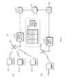
- FIG. 1is a block diagram of a system in which the invention is implemented.
- FIGS. 2A and 2Bprovide examples of Media Access Control (MAC) layer data frames or messages that may be used to format transmitted signals.
- MACMedia Access Control
- FIG. 3is a sequence of steps performed by an antenna controller in order to process received signals according to a first embodiment.
- FIG. 4is a process diagram for the antenna controller according to a second embodiment.
- FIG. 5is yet another process which the controller may perform.
- FIG. 6illustrates a message and its acknowledgement.
- FIG. 7is a sequence of steps using acknowledgement suppression to confirm antenna angle setting.
- FIG. 8is a sequence of steps using contention-free periods to confirm antenna angle setting.
- FIG. 1is a high level block diagram of a wireless data communication network 10 in which the invention may be deployed, such as network for providing wireless connectivity between a number of end nodes 12 and a data network such as the Internet 18 through access point equipment 14 .
- a first wireless Local Area Network (LAN) 11 - 1formed by the nodes 12 - 1 - 1 , 12 - 1 - 2 , . . . 12 - 1 -n. These nodes 12 - 1 communicate with each other and a first access point 14 - 1 using specially formatted radio signals.
- a directional antenna array 20 - 1is used with the access point 14 - 1 in the first wireless LAN 11 - 1 .
- the access point 14 - 1is responsible for converting received radio frequency signals to their appropriate wired format such as the TCP/IP format suitable for Internet communications through a gateway 16 - 1 .
- the gateway 16 - 1may be a router, switch, or other internetworking device.
- a similar second wireless LAN 11 - 2involves the nodes 12 - 2 -p, antenna 20 - 2 , access point 14 - 2 , and gateway 16 - 2 .
- Each of the nodes 12include a remote station which is typically a portable Personal Computer (PC) equipped with a wireless network interface card (NIC).
- PCPersonal Computer
- NICwireless network interface card
- Other types of computing equipmentsuch as Personal Digital Assistants (PDAs), desktop computing equipment, and other networkable devices are possible.
- PDAsPersonal Digital Assistants
- desktop computing equipmentand other networkable devices are possible.
- the access point (AP) 14 - 1acts as a sort of bridge between the wireless network 10 and wired networks such as the Internet 18 .
- the access point 14 - 1acts as a base station for the physical layer signaling used in the wireless network, aggregating access for multiple wireless nodes 12 - 1 - 1 , . . . 12 - 1 -n onto the wired network.
- the access point 14usually consists of radio receiver and transmitter equipment and a wired network interface such as an IEEE 802.11 Ethernet interface. If the access point 14 is to provide connectivity to other networks, it may typically include bridging software conforming to, for example, 802.1 Bridging Standard, and other software such as firewalls and the like. It therefore acts as a router or bridge, from the perspective of higher layer data networking protocols.
- the access point 14 - 1also contains a table 25 which is capable of storing identification information for the nodes 12 such as a unit identification and an associated antenna setting parameters, such as an angle.
- An array controller 30that permits steering of the particular direction of the antenna 20 - 1 such as by specifying an angle.
- Signal receiving equipment in the access point 14 - 1also contains detection circuits that are capable of determining a received signal metric, such as Received Signal Strength Indication (RSSI), Bit Error Rate (BER), noise power level, or other such measures of receive signal quality.
- RSSIReceived Signal Strength Indication
- BERBit Error Rate
- FIGS. 2A and 2Billustrate the format of a message or frame structure such as described in the wireless LAN specification IEEE 802.11b.
- the messageconsists of a Media Access Control (MAC) layer preamble, header, and payload portion or Protocol Specific Data Unit (PSDU).
- MACMedia Access Control
- PSDUProtocol Specific Data Unit
- the messages in IEEE 802.11may be either a long preamble-type as used in the connection with the message shown in FIG. 2A , as well as the short preamble-type as shown in FIG. 2B .
- the different frame formatsare associated with supporting different data rates.
- DBPSKDouble Binary Phase Shift Keying
- DQPSKDouble Quadrature Phase Shift Keying
- the preamble and header portions of the frameutilize a more robust encoding scheme than the data payload portions. This permits more reliable detection of the header and preamble in the presence of noise.
- the preamble of either formats shown in FIG. 2A or 2 Binclude an indication of the particular senders, such as in the SFD portion.
- FIG. 3illustrates a flow chart of a process for receiving wireless network signals in accordance with the invention. The process is performed in an access point 14 as it receives signals from nodes 12 , and may typically be carried out during physical layer processing.
- the antenna 20 associated with the respective access point 14is initially set into an omni-directional mode.
- a state 320is then entered in which the preamble portion and/or header of a received signal is detected.
- state 330the initial portion of the received signal is examined to identify it uniquely. If the received signal is unknown, e.g., the node 12 which originated the signal has not been seen before, the antenna is then set in an angle search mode in state 322 . In this mode, the antenna 20 is therefore stepped through a sequence of directional angles to find a direction of maximum received signal strength, signal quality, lowest Bit Error Rate (BER) or other signal quality metric.
- BERBit Error Rate
- state 323when this angle is determined, it is recorded and associated with the device identification information, such as a table entry 25 associated with that device.
- the table as shown in FIG. 1may be kept by the access point 14 as part of its message routing table.
- the access point 14may then enter a state 324 in which during active receptions, the optimum angle is continuously adjusted while receiving the payload data portion of the frame. If reception of the frame is then lost or otherwise completed, then the last best known angle is recoded in the table, and processing returns to the initial state 310 .
- processingproceeds to a state 325 in which the last known angle is looked up in the table 25 .
- This last known angleis then used by the controller 30 to steer the array to the last known position.
- the arraythen remains in this last known position at least for reception of the payload portion of the signal in state 326 .
- the state 324may continue to be entered as the payload portion is being received whereby the angle is continuously adjusted while it is active and any updates are then recorded in the table 25 .
- the state 328may be entered from state 326 if the unit is in a relay mode, where the best received angle may be used a subsequent transmissions to that same node.
- FIG. 4is a diagram of a slightly modified process that may also be used according to the present invention.
- the number of steps of the process in FIG. 4correspond, more or less, to the steps of FIG. 3 .
- the antenna 20is initially set in step 310 to an omni-directional mode.
- higher layer level signalingis examined.
- a Request to Send (RTS) messageis detected such as at a link layer.
- the messageis again examined to see if the originator has a known identification.
- RTSRequest to Send
- steps 325 and 326proceed as previously where the last known angle associated with that sender is determined in step 325 and the antenna 20 is steered to the last known angle in step 326 .
- the unitwill then send a Clear to Send (CTS) message in step 340 with the antenna now set to the last known angle.
- CTSClear to Send
- step 330If however, back in step 330 , if the identification of the detected RTS is not known, then an angle search proceeds in state 322 and the ID and angle of the best reception state is recorded in step 323 . Step 324 continues as previously where the angle may be adjusted while active payload data is being received. Step 345 may be entered when the signal detection is lost and/or an end of message (EOM) is received.
- EOMend of message
- a Clear to Send (CTS) messageis sent step 340 .
- CTSClear to Send
- a CTS acknowledgementis waited for in step 342 .
- the acknowledgementwould typically be received within a predetermined amount of time or otherwise a time-out condition exists. If the acknowledgement is received, then the specified angle is presumed to be okay and in state 344 and then processing may proceed to step 324 . However, if a time-out does occur in step 342 , then it is presumed that the angle to which the antenna 20 was steered is bad and therefore the angle search state 322 must be entered.
- a first step 500the antenna is set to a directional mode. For example, it is typically common that the subscriber will have the given information with respect to its candidate direction in which the base station exists.
- a Request to Send (RTS) messageis sent in a directional mode.
- RTSRequest to Send
- step 520if a Clear to Send (CTS) message is received back from the base station, then it can be presumed that the antenna direction setting is okay in step 522 and the link layer communications may proceed in step 524 .
- CTSClear to Send
- step 520If however, in step 520 there is no CTS received within a time-out period, then it is presumed that the antenna is incorrectly set. Thus, an omni-directional mode is entered in step 528 and the RTS message is sent in step 540 . Processing then proceeds from that point similar to that described in FIG. 3 and/or FIG. 4 , i.e., an angle search is performed to properly set the antenna in step 544 and the setting is recorded in step 548 .
- FIG. 5illustrates a sequence of higher level messages that may be sent in a typical network computer environment.
- a source stationwhich may either be the access point 14 - 1 or remote stations 12 , sends a message 610 .
- the message 610may consist of one or more packets that have the previously described preamble, header, and payload portions.
- the messagemay be a relatively detailed message or may be a relatively simple message such as a request to set up a connection and send further information.
- This acknowledgement message 612may have a preamble portion and a header portion that specifically has a header or payload portion that is a known acknowledgement (ACK) format.
- ACKacknowledgement
- the higher layer protocolmay be, for example, implemented at a link layer.
- the present inventionmay make use of these higher layer protocol units to invoke other protocols to help train the antenna.
- the acknowledgement message 612is sent upon receipt of a proper message 610 at the destination station. However, situations may also exit 614 in which no acknowledgement is sent from the destination. This is typically done if the message is not received within a predetermined period of time at the destination. In that manner, the source will know to attempt to retransmit the message 610 .
- This acknowledgement protocolis typical of higher layer protocols in widespread usage in data communication networks typical of the Transmission Control Protocol/Internet Protocol (TCP/IP) protocol used in Internet data communications.
- TCP/IPTransmission Control Protocol/Internet Protocol
- 802.11B Standardis potentially acceptable in this regard.
- protocols such as the 802.11A Wireless LAN Standardmay not provide sufficient duration preamble.
- the wireless LAN protocolswork on a similar radio link protocol that is similar to Ethernet.
- a positive acknowledgement radio link protocolis used. For example, if correctly received packets are acknowledged whereas incorrectly received packets are not.
- the non-acknowledgement testcan be performed at a radio link protocol layer and/or higher level layers.
- tenant array 20is first steered to an omni-directional state.
- a transmissionis received.
- a state 714is entered in which the acknowledgement 612 that would normally be sent is suppressed. Therefore, the unit enters a mode in which no acknowledgement is sent 614 .
- the suppression of the acknowledgement in state 714causes a second receipt of the packet in state 718 .
- the received qualityis compared. If the received quality is not adequate, then the process loops back to state 714 in which the acknowledgement is suppressed once again.
- Step 714 through 720are continuously executed until an acceptable received packet quality is determined in state 720 . When this occurs, control passes to state 722 in which an acknowledgement is presently sent.
- the set angleis then recorded with the identification of the unit for subsequent communication with that unit.
- the anglemay be more appropriately set upon the second try in state 716 , such as in shown in FIG. 3 .
- the angle search associated with step 714 through 720can proceed more expeditiously.
- a contention-free windowcan be set up by certain protocols using a so-called PCF or HCF mode.
- PCFa means is provided for discovering the best angle that can be controlled by an access point as to which units will be transmitting during a certain period of time.
- the identification of the unit being known in advancethe antenna can be steered to the last known direction for the communication prior to its receipt.
- the control messagesmay be set up while an omni-directional mode then when transmitting to the remote unit, the directed mode can in HCF or Hybrid Coordination Function can be determined.
- an 802.11 access point 12has essentially two modes, including a distributed correlation function (DCF) mode 810 and a point coordination function (PCF) mode 830 .
- DCFdistributed correlation function
- PCFpoint coordination function
- communicationis basically contention-based whereby any one of the subscriber units 12 may be allowed to attempt to send messages to the access point 14 at any point in time.
- the PCF mode 830is entered into from time to time to provide a mode in which contention-free communication is possible.
- the systemguarantees to a particular subscriber unit 12 that it will be able to have exclusive access to the airwaves and send messages to the access point 814 , free of any collision with other subscriber units 12 .
- the access point 14receives requests on a sporadic basis from particular subscriber units 12 to be granted contention-free areas (CF) at a later time.
- the PCF modeis entered in state 830 .
- the antennais first sent to an omni-directional mode 832 .
- a beacon signalis sent to all subscriber units 12 to indicate that the PCF mode is being entered into. This is a signal to all units to listen for upcoming polling information to determine if they will be granted a contention-free period.
- a poll signalis then sent out at state 834 .
- a response to the poll signal in state 834determines a particular identifier of one of the subscriber units 12 which is to be granted contention-free access during the PCF mode. It should be understood that during any given PCF mode, a number of different subscriber units 12 may be granted exclusive use or may be granted a contention-free period one after the other.
- the access point in state 834polls the first such unit on its list.
- the poll messageis sent by steering the antenna to the last known location or correct angle for the particular identified subscriber unit 12 .
- This particular PCF messageis then sent in step 838 as a contention-free message.
- Steps 834 through 838are then continuously executed until each of the subscriber units that had requested a CF eventually be granted their turn at a contention-free period.
- the antennaUpon each subsequent such subscriber unit 12 being accessed during the contention-free period, the antenna will be steered to its respective appropriate direction in the state 836 prior to sending the associated PCF message for the particular subscriber unit 12 .
- the access unitmay then steer the antenna array 20 back to an omni-directional mode so that in a state 840 , a contention-free period end message may be sent to all of the subscriber units so that they may understand that the end of PCF mode has been reached and that the system is then now returning to a DCF mode in state 810 .
Landscapes
- Engineering & Computer Science (AREA)
- Computer Networks & Wireless Communication (AREA)
- Signal Processing (AREA)
- Mobile Radio Communication Systems (AREA)
- Radio Relay Systems (AREA)
- Small-Scale Networks (AREA)
Abstract
Description
Claims (31)
Priority Applications (13)
| Application Number | Priority Date | Filing Date | Title |
|---|---|---|---|
| US09/952,198US7224685B2 (en) | 2001-09-13 | 2001-09-13 | Method of detection of signals using an adaptive antenna in a peer-to-peer network |
| MXPA04002364AMXPA04002364A (en) | 2001-09-13 | 2002-09-12 | Method of detection of signals using an adaptive antenna in a peer-to-peer network. |
| EP02775806AEP1436854A2 (en) | 2001-09-13 | 2002-09-12 | Method of detection of signals using an adaptive antenna in a peer-to-peer network |
| KR10-2004-7003723AKR20040029174A (en) | 2001-09-13 | 2002-09-12 | Method of detection of signals using an adaptive antenna in a peer-to-peer network |
| BRPI0212793-8ABR0212793A (en) | 2001-09-13 | 2002-09-12 | method for operating a wireless data communication system |
| JP2003527831AJP2005503061A (en) | 2001-09-13 | 2002-09-12 | Signal detection method using adaptive antenna in peer-to-peer network |
| CNA028202813ACN1568585A (en) | 2001-09-13 | 2002-09-12 | Method of detection of signals using an adaptive antenna in a peer-to-peer network |
| PCT/US2002/029147WO2003023895A2 (en) | 2001-09-13 | 2002-09-12 | Method of detection of signals using an adaptive antenna in a peer-to-peer network |
| AU2002341656AAU2002341656B2 (en) | 2001-09-13 | 2002-09-12 | Method of detection of signals using an adaptive antenna in a peer-to-peer network |
| CA002468021ACA2468021A1 (en) | 2001-09-13 | 2002-09-12 | Method of detection of signals using an adaptive antenna in a peer-to-peer network |
| KR1020077010394AKR20070055634A (en) | 2001-09-13 | 2002-09-12 | Method for detecting signal using adaptive antenna in peer-to-peer network |
| US10/774,860US7586880B2 (en) | 2001-09-13 | 2004-02-09 | Method of detection of signals using an adaptive antenna in a peer-to-peer network |
| NO20041080ANO20041080L (en) | 2001-09-13 | 2004-03-15 | Method for detecting signals using an adaptive antenna in a "peer-to-peer" network |
Applications Claiming Priority (1)
| Application Number | Priority Date | Filing Date | Title |
|---|---|---|---|
| US09/952,198US7224685B2 (en) | 2001-09-13 | 2001-09-13 | Method of detection of signals using an adaptive antenna in a peer-to-peer network |
Related Child Applications (1)
| Application Number | Title | Priority Date | Filing Date |
|---|---|---|---|
| US10/774,860ContinuationUS7586880B2 (en) | 2001-09-13 | 2004-02-09 | Method of detection of signals using an adaptive antenna in a peer-to-peer network |
Publications (2)
| Publication Number | Publication Date |
|---|---|
| US20030048770A1 US20030048770A1 (en) | 2003-03-13 |
| US7224685B2true US7224685B2 (en) | 2007-05-29 |
Family
ID=25492657
Family Applications (2)
| Application Number | Title | Priority Date | Filing Date |
|---|---|---|---|
| US09/952,198Expired - Fee RelatedUS7224685B2 (en) | 2001-09-13 | 2001-09-13 | Method of detection of signals using an adaptive antenna in a peer-to-peer network |
| US10/774,860Expired - Fee RelatedUS7586880B2 (en) | 2001-09-13 | 2004-02-09 | Method of detection of signals using an adaptive antenna in a peer-to-peer network |
Family Applications After (1)
| Application Number | Title | Priority Date | Filing Date |
|---|---|---|---|
| US10/774,860Expired - Fee RelatedUS7586880B2 (en) | 2001-09-13 | 2004-02-09 | Method of detection of signals using an adaptive antenna in a peer-to-peer network |
Country Status (11)
| Country | Link |
|---|---|
| US (2) | US7224685B2 (en) |
| EP (1) | EP1436854A2 (en) |
| JP (1) | JP2005503061A (en) |
| KR (2) | KR20070055634A (en) |
| CN (1) | CN1568585A (en) |
| AU (1) | AU2002341656B2 (en) |
| BR (1) | BR0212793A (en) |
| CA (1) | CA2468021A1 (en) |
| MX (1) | MXPA04002364A (en) |
| NO (1) | NO20041080L (en) |
| WO (1) | WO2003023895A2 (en) |
Cited By (15)
| Publication number | Priority date | Publication date | Assignee | Title |
|---|---|---|---|---|
| US20050141545A1 (en)* | 2003-11-10 | 2005-06-30 | Yaron Fein | Performance of a wireless communication system |
| US20050239451A1 (en)* | 2004-04-02 | 2005-10-27 | Shalini Periyalwar | System and method for peer-to-peer communication in cellular systems |
| US20060109794A1 (en)* | 2004-11-08 | 2006-05-25 | Nokia Corporation | Communication system |
| US20070189325A1 (en)* | 2002-09-30 | 2007-08-16 | Ipr Licensing, Inc. | Method and apparatus for antenna steering for WLAN |
| US20100056190A1 (en)* | 2008-08-29 | 2010-03-04 | Eldering Charles A | Adaptive Antenna Weighting System for Wireless Local Area and Personal Area Networks |
| US20100056191A1 (en)* | 2008-08-29 | 2010-03-04 | Eldering Charles A | Weighting Factor Adjustment in Adaptive Antenna Arrays |
| US20100054180A1 (en)* | 2008-08-29 | 2010-03-04 | Eldering Charles A | Method and System for Adaptive Antenna Array Pairing |
| US20100150077A1 (en)* | 2006-06-06 | 2010-06-17 | Qualcomm Incorporated | Apparatus and method for wireless communication via at least one of directional and omni-direction antennas |
| US20100329192A1 (en)* | 2009-06-24 | 2010-12-30 | Hwang Timothy H | Wireless Network Access using an Adaptive Antenna Array |
| US20120046761A1 (en)* | 2010-08-23 | 2012-02-23 | Oki Semiconductor Co., Ltd. | Information processing device, communication system, and information processing method |
| US20120044834A1 (en)* | 2007-01-18 | 2012-02-23 | Science Applications International Corporation | Mechanism for Automatic Network Formation and Medium Access Coordination |
| US8422540B1 (en) | 2012-06-21 | 2013-04-16 | CBF Networks, Inc. | Intelligent backhaul radio with zero division duplexing |
| US8467363B2 (en) | 2011-08-17 | 2013-06-18 | CBF Networks, Inc. | Intelligent backhaul radio and antenna system |
| US9525473B2 (en) | 2009-04-15 | 2016-12-20 | Sony Corporation | Communication device and communication method, computer program, and communication system |
| US11012106B2 (en) | 2016-09-23 | 2021-05-18 | Qualcomm Incorporated | Implementation of improved omni mode signal reception |
Families Citing this family (103)
| Publication number | Priority date | Publication date | Assignee | Title |
|---|---|---|---|---|
| KR100364368B1 (en)* | 2000-10-18 | 2002-12-12 | 엘지전자 주식회사 | Private Network Using Bluetooth and Communication Method Using the Network |
| US7269198B1 (en)* | 2001-11-19 | 2007-09-11 | Bbn Technologies Corp. | Systems and methods for beaconing in wireless networks with low probability of detection |
| US20030119558A1 (en)* | 2001-12-20 | 2003-06-26 | Karl Steadman | Adaptive antenna pattern formation in wireless ad-hoc packet-switched networks |
| US7471667B2 (en)* | 2002-01-09 | 2008-12-30 | Nxp B.V. | Coexistence of modulation schemes in a WLAN |
| US7075902B2 (en)* | 2002-02-11 | 2006-07-11 | Hrl Laboratories, Llc | Apparatus, method, and computer program product for wireless networking using directional signaling |
| US7382756B2 (en)* | 2002-05-04 | 2008-06-03 | Broadcom Corporation | Integrated user and radio management in a wireless network environment |
| US7532895B2 (en) | 2002-05-20 | 2009-05-12 | Air Defense, Inc. | Systems and methods for adaptive location tracking |
| US7042852B2 (en) | 2002-05-20 | 2006-05-09 | Airdefense, Inc. | System and method for wireless LAN dynamic channel change with honeypot trap |
| US7383577B2 (en) | 2002-05-20 | 2008-06-03 | Airdefense, Inc. | Method and system for encrypted network management and intrusion detection |
| US7086089B2 (en) | 2002-05-20 | 2006-08-01 | Airdefense, Inc. | Systems and methods for network security |
| US7277404B2 (en) | 2002-05-20 | 2007-10-02 | Airdefense, Inc. | System and method for sensing wireless LAN activity |
| US7058796B2 (en) | 2002-05-20 | 2006-06-06 | Airdefense, Inc. | Method and system for actively defending a wireless LAN against attacks |
| US7322044B2 (en)* | 2002-06-03 | 2008-01-22 | Airdefense, Inc. | Systems and methods for automated network policy exception detection and correction |
| KR20050033051A (en)* | 2002-06-17 | 2005-04-08 | 아이피알 라이센싱, 인코포레이티드 | Antenna steering scheduler for mobile station in wireless local area network |
| JP2004282643A (en)* | 2003-03-18 | 2004-10-07 | Hitachi Ltd | Radio base station and radio base station control method |
| US7324804B2 (en)* | 2003-04-21 | 2008-01-29 | Airdefense, Inc. | Systems and methods for dynamic sensor discovery and selection |
| US20040210654A1 (en)* | 2003-04-21 | 2004-10-21 | Hrastar Scott E. | Systems and methods for determining wireless network topology |
| US7522908B2 (en)* | 2003-04-21 | 2009-04-21 | Airdefense, Inc. | Systems and methods for wireless network site survey |
| US7359676B2 (en)* | 2003-04-21 | 2008-04-15 | Airdefense, Inc. | Systems and methods for adaptively scanning for wireless communications |
| US7355996B2 (en) | 2004-02-06 | 2008-04-08 | Airdefense, Inc. | Systems and methods for adaptive monitoring with bandwidth constraints |
| US7239894B2 (en)* | 2003-05-30 | 2007-07-03 | Microsoft Corporation | Using directional antennas to enhance throughput in wireless networks |
| US7130586B2 (en)* | 2003-05-30 | 2006-10-31 | Microsoft Corporation | Using directional antennas to mitigate the effects of interference in wireless networks |
| US7295806B2 (en) | 2003-05-30 | 2007-11-13 | Microsoft Corporation | Using directional antennas to enhance wireless mesh networks |
| US7047046B2 (en)* | 2003-06-19 | 2006-05-16 | Ipr Licensing, Inc. | Antenna steering for an access point based upon probe signals |
| US7609648B2 (en)* | 2003-06-19 | 2009-10-27 | Ipr Licensing, Inc. | Antenna steering for an access point based upon control frames |
| US7103386B2 (en)* | 2003-06-19 | 2006-09-05 | Ipr Licensing, Inc. | Antenna steering and hidden node recognition for an access point |
| CN1817053A (en)* | 2003-06-19 | 2006-08-09 | 美商智慧财产权授权股份有限公司 | Antenna steering for an access point based upon probe signals |
| CN1906858A (en)* | 2003-06-19 | 2007-01-31 | 美商智慧财产权授权股份有限公司 | Antenna steering method for an 802.11 station |
| US7587173B2 (en) | 2003-06-19 | 2009-09-08 | Interdigital Technology Corporation | Antenna steering for an access point based upon spatial diversity |
| JP2005012683A (en)* | 2003-06-20 | 2005-01-13 | Mitsubishi Electric Corp | Wireless communication method and wireless communication system |
| WO2005020509A1 (en)* | 2003-08-26 | 2005-03-03 | Philips Intellectual Property & Standards Gmbh | Wireless communication system for electronic devices |
| US7668201B2 (en)* | 2003-08-28 | 2010-02-23 | Symbol Technologies, Inc. | Bandwidth management in wireless networks |
| US20050096091A1 (en)* | 2003-10-31 | 2005-05-05 | Jacob Sharony | Method and system for wireless communications using multiple frequency band capabilities of wireless devices |
| US7215926B2 (en)* | 2003-12-05 | 2007-05-08 | Microsoft Corporation | Enhanced mode technique for growing mesh networks |
| US20050135321A1 (en)* | 2003-12-17 | 2005-06-23 | Jacob Sharony | Spatial wireless local area network |
| US20050164744A1 (en)* | 2004-01-28 | 2005-07-28 | Du Toit Nicolaas D. | Apparatus and method operable in a wireless local area network incorporating tunable dielectric capacitors embodied within an inteligent adaptive antenna |
| US7586881B2 (en)* | 2004-02-13 | 2009-09-08 | Broadcom Corporation | MIMO wireless communication greenfield preamble formats |
| US7428428B2 (en)* | 2004-04-28 | 2008-09-23 | Hong Kong Applied Science And Technology Research Institute Co., Ltd. | Systems and methods for wireless network range extension |
| US7366464B2 (en)* | 2004-06-04 | 2008-04-29 | Interdigital Technology Corporation | Access point operating with a smart antenna in a WLAN and associated methods |
| US7349701B2 (en) | 2004-06-15 | 2008-03-25 | Rotani, Inc. | Method and apparatus for creating shape antenna radiation patterns |
| US7400860B2 (en) | 2004-06-15 | 2008-07-15 | Rotani, Inc. | Method and apparatus for increasing data throughput |
| US8504110B2 (en) | 2004-09-10 | 2013-08-06 | Interdigital Technology Corporation | Method and apparatus for transferring smart antenna capability information |
| EP3576310B1 (en)* | 2004-09-10 | 2023-03-22 | InterDigital Technology Corporation | Implementing a smart antenna in a wireless local area network |
| US7428408B2 (en)* | 2004-09-20 | 2008-09-23 | Interdigital Technology Corporation | Method for operating a smart antenna in a WLAN using medium access control information |
| US8196199B2 (en)* | 2004-10-19 | 2012-06-05 | Airdefense, Inc. | Personal wireless monitoring agent |
| US20060123133A1 (en)* | 2004-10-19 | 2006-06-08 | Hrastar Scott E | Detecting unauthorized wireless devices on a wired network |
| KR100608915B1 (en)* | 2004-11-17 | 2006-08-08 | 한국전자통신연구원 | WLAN Media Access Control Method using Pseudo Time Division Multiplexing |
| US20060209876A1 (en) | 2005-02-10 | 2006-09-21 | Interdigital Technology Corporation | Access point using directional antennas for uplink transmission in a WLAN |
| US7664013B2 (en)* | 2005-02-28 | 2010-02-16 | Cisco Technology, Inc. | Loop prevention technique for MPLS using service labels |
| US20060209772A1 (en)* | 2005-03-15 | 2006-09-21 | University Of Florida Research Foundation, Inc. | Coordinated directional medium access control in a wireless network |
| US20060221904A1 (en)* | 2005-03-31 | 2006-10-05 | Jacob Sharony | Access point and method for wireless multiple access |
| US20060221873A1 (en)* | 2005-03-31 | 2006-10-05 | Jacob Sharony | System and method for wireless multiple access |
| US20060221928A1 (en)* | 2005-03-31 | 2006-10-05 | Jacob Sharony | Wireless device and method for wireless multiple access |
| US7907971B2 (en)* | 2005-08-22 | 2011-03-15 | Airgain, Inc. | Optimized directional antenna system |
| US7577424B2 (en) | 2005-12-19 | 2009-08-18 | Airdefense, Inc. | Systems and methods for wireless vulnerability analysis |
| KR101319870B1 (en)* | 2006-01-05 | 2013-10-18 | 엘지전자 주식회사 | Method for handover in mobile communication system |
| US20070160016A1 (en)* | 2006-01-09 | 2007-07-12 | Amit Jain | System and method for clustering wireless devices in a wireless network |
| ATE526801T1 (en)* | 2006-01-11 | 2011-10-15 | Qualcomm Inc | COMMUNICATION METHOD AND APPARATUS FOR SENDING PRIORITY INFORMATION VIA BEACON SIGNALS |
| US7715800B2 (en) | 2006-01-13 | 2010-05-11 | Airdefense, Inc. | Systems and methods for wireless intrusion detection using spectral analysis |
| EP2461491A1 (en) | 2006-02-28 | 2012-06-06 | Rotani Inc. | Methods and apparatus for overlapping MIMO antenna physical sectors |
| US8089881B2 (en) | 2006-03-03 | 2012-01-03 | Qualcomm Incorporated | Method and apparatus for increasing spectrum use efficiency in a mesh network |
| US7971251B2 (en)* | 2006-03-17 | 2011-06-28 | Airdefense, Inc. | Systems and methods for wireless security using distributed collaboration of wireless clients |
| US20070218874A1 (en)* | 2006-03-17 | 2007-09-20 | Airdefense, Inc. | Systems and Methods For Wireless Network Forensics |
| US7567651B2 (en)* | 2006-03-30 | 2009-07-28 | Zeljko John Serceki | Directional antenna system for wireless X-ray devices |
| US20090021343A1 (en)* | 2006-05-10 | 2009-01-22 | Airdefense, Inc. | RFID Intrusion Protection System and Methods |
| US7970013B2 (en) | 2006-06-16 | 2011-06-28 | Airdefense, Inc. | Systems and methods for wireless network content filtering |
| US8281392B2 (en)* | 2006-08-11 | 2012-10-02 | Airdefense, Inc. | Methods and systems for wired equivalent privacy and Wi-Fi protected access protection |
| US8248970B2 (en)* | 2006-12-19 | 2012-08-21 | Airgain, Inc. | Optimized directional MIMO antenna system |
| US7652624B2 (en)* | 2007-03-06 | 2010-01-26 | Intel Corporation | Millimeter-wave communication stations with directional antennas and methods for fast link recovery |
| US8041333B2 (en)* | 2007-06-14 | 2011-10-18 | Broadcom Corporation | Method and system for 60 GHz antenna adaptation and user coordination based on base station beacons |
| JP5244197B2 (en)* | 2008-01-09 | 2013-07-24 | コーニンクレッカ フィリップス エレクトロニクス エヌ ヴィ | Wireless device discovery method and system in a wireless network using directional antennas |
| US8335203B2 (en)* | 2008-03-11 | 2012-12-18 | Intel Corporation | Systems and methods for polling for dynamic slot reservation |
| JP4578539B2 (en)* | 2008-06-17 | 2010-11-10 | 株式会社バッファロー | Wireless communication system, wireless LAN connection device, wireless LAN relay device |
| US8223739B2 (en) | 2008-10-29 | 2012-07-17 | Intel Corporation | Method and apparatus of dynamic bandwidth management |
| US8942210B2 (en)* | 2008-11-12 | 2015-01-27 | Qualcomm Incorporated | Method and apparatus for channel access in a wireless communications system |
| JP5141587B2 (en)* | 2009-02-13 | 2013-02-13 | ソニー株式会社 | COMMUNICATION DEVICE, COMMUNICATION CONTROL METHOD, AND COMMUNICATION SYSTEM |
| JP2010212804A (en)* | 2009-03-06 | 2010-09-24 | Sony Corp | Communication device and communication method, computer program, and communication system |
| US8223072B2 (en)* | 2009-04-29 | 2012-07-17 | Aruba Networks, Inc. | Multi-pattern wireless frame transmission |
| FR2947388B1 (en)* | 2009-06-26 | 2012-05-18 | Thales Sa | ANTENNA POINT ASSISTING METHOD, ASSISTED POINT ANTENNA USING THE SAME, AND NOMAD TERMINAL HAVING SUCH ANTENNA |
| US8224236B2 (en)* | 2009-07-17 | 2012-07-17 | Fujitsu Semiconductor Limited | System and method for switching an antenna in a relay station |
| JP5347889B2 (en)* | 2009-10-09 | 2013-11-20 | 株式会社リコー | Wireless communication apparatus, image processing apparatus, and wireless communication method |
| US8351406B2 (en)* | 2009-12-21 | 2013-01-08 | Intel Corporation | Techniques for dynamic resource allocation |
| JP5321508B2 (en)* | 2010-03-11 | 2013-10-23 | ソニー株式会社 | COMMUNICATION DEVICE, COMMUNICATION CONTROL METHOD, AND COMMUNICATION SYSTEM |
| US8451760B2 (en)* | 2010-07-30 | 2013-05-28 | Aruba Networks, Inc. | Power savings in access points |
| JP5681713B2 (en)* | 2011-03-29 | 2015-03-11 | パナソニックIpマネジメント株式会社 | Remote control system and remote control |
| US9456357B2 (en) | 2012-07-27 | 2016-09-27 | Aruba Networks, Inc. | Adaptive antenna pattern management for wireless local area networks |
| EP2951604A1 (en)* | 2013-02-01 | 2015-12-09 | Telefonaktiebolaget LM Ericsson (PUBL) | A method for antenna alignment in a non line-of-sight scenario |
| WO2014144920A2 (en)* | 2013-03-15 | 2014-09-18 | Maxtena, Inc. | Method and apparatus for establishing communications with a satellite |
| GB201421388D0 (en)* | 2014-12-02 | 2015-01-14 | Kolokotronis Dimitris | Dynamic azimuth adjustment for cellular repeater antenna systems |
| CN105636068A (en)* | 2015-10-30 | 2016-06-01 | 中国电信股份有限公司广东无线网络运营中心 | Indoor coverage device monitoring method and system and warning collector |
| EP3375108A4 (en)* | 2015-11-11 | 2019-10-23 | Ruckus Wireless, Inc. | DEWLAN TREATMENT |
| CN107231642B (en)* | 2016-03-25 | 2020-10-16 | 上海宽翼通信科技有限公司 | WIFI wireless router and automatic antenna direction optimization method thereof |
| WO2017166139A1 (en) | 2016-03-30 | 2017-10-05 | 广东欧珀移动通信有限公司 | Relay transmission method and device |
| PT3466159T (en)* | 2016-05-31 | 2019-12-24 | Teleste Oyj | METHOD AND SYSTEM FOR DYNAMIC MANAGEMENT OF MULTIMEDIA CONTENT IN VEHICLES |
| US10182315B2 (en) | 2016-09-20 | 2019-01-15 | Deeyook Location Technologies Ltd. | Identifying angle of departure of multi-antenna transmitters |
| US11215688B2 (en) | 2016-09-20 | 2022-01-04 | Deeyook Location Technologies Ltd. | Identifying angle of departure of multi-antenna transmitters |
| US9814051B1 (en) | 2016-09-20 | 2017-11-07 | Deeyook Location Technologies Ltd. | Identifying angle of departure of multi-antenna transmitters |
| CN109716857B (en)* | 2017-01-26 | 2021-09-21 | 华为技术有限公司 | Relay determination method and device |
| WO2018145796A1 (en) | 2017-02-08 | 2018-08-16 | British Telecommunications Public Limited Company | Cellular telecommunications network |
| CN108183344B (en)* | 2017-12-05 | 2024-02-02 | 西安华讯天基通信技术有限公司 | Directional antenna and method for transmitting and receiving data by directional antenna |
| US12273848B2 (en) | 2019-12-31 | 2025-04-08 | Deeyook Location Technologies Ltd | Interferometric location sensing |
| US11240846B2 (en) | 2020-02-06 | 2022-02-01 | Deeyook Location Technologies Ltd. | Anonymous collection of directional transmissions |
| CN114499715B (en)* | 2021-12-23 | 2024-03-19 | 云尖信息技术有限公司 | Method and device for detecting intelligent antenna array, computer equipment and storage medium |
Citations (12)
| Publication number | Priority date | Publication date | Assignee | Title |
|---|---|---|---|---|
| US4021813A (en) | 1974-07-01 | 1977-05-03 | The United States Of America As Represented By The Secretary Of The Navy | Geometrically derived beam circular antenna array |
| US5027125A (en) | 1989-08-16 | 1991-06-25 | Hughes Aircraft Company | Semi-active phased array antenna |
| US5293172A (en) | 1992-09-28 | 1994-03-08 | The Boeing Company | Reconfiguration of passive elements in an array antenna for controlling antenna performance |
| US5767807A (en) | 1996-06-05 | 1998-06-16 | International Business Machines Corporation | Communication system and methods utilizing a reactively controlled directive array |
| US5905473A (en) | 1997-03-31 | 1999-05-18 | Resound Corporation | Adjustable array antenna |
| US5963559A (en)* | 1995-10-31 | 1999-10-05 | Nec Corporation | Radio transmission with a slow transmission mode used when retransmission of a data frame fails even repeated |
| US6100843A (en) | 1998-09-21 | 2000-08-08 | Tantivy Communications Inc. | Adaptive antenna for use in same frequency networks |
| US6239757B1 (en) | 1994-04-07 | 2001-05-29 | Murata Manufacturing Co., Ltd. | Communication module for a means of transportation |
| US6239756B1 (en) | 1999-11-19 | 2001-05-29 | Tantivy Communications | Antenna array with housing |
| EP1130837A2 (en) | 2000-02-29 | 2001-09-05 | Hughes Electronics Corporation | Physical layer header for packet data |
| US20020097700A1 (en)* | 2001-01-19 | 2002-07-25 | Ari Alastalo | Apparatus, and associated method, for utilizing antenna information determinative of antenna operation in a wireless mesh network |
| US6611231B2 (en)* | 2001-04-27 | 2003-08-26 | Vivato, Inc. | Wireless packet switched communication systems and networks using adaptively steered antenna arrays |
Family Cites Families (10)
| Publication number | Priority date | Publication date | Assignee | Title |
|---|---|---|---|---|
| US529172A (en)* | 1894-11-13 | Machine for making egg-fillers | ||
| US5846088A (en)* | 1997-01-06 | 1998-12-08 | Reichert; Jonathan F. | Teaching appparatus for magnetic torque experiments |
| US5628052A (en)* | 1994-09-12 | 1997-05-06 | Lucent Technologies Inc. | Wireless communication system using distributed switched antennas |
| US7043262B2 (en)* | 1998-03-06 | 2006-05-09 | Hans Peter Nageli | Two-way pager and method for communicating preset messages over the global system for mobile communications (GSM/GPRS) network |
| AU4278600A (en)* | 1999-04-27 | 2000-11-10 | Brian De Champlain | Single receiver wireless tracking system |
| WO2000074306A2 (en)* | 1999-05-28 | 2000-12-07 | Basic Resources, Inc. | Wireless transceiver network employing node-to-node data messaging |
| US6757263B1 (en)* | 2000-04-13 | 2004-06-29 | Motorola, Inc. | Wireless repeating subscriber units |
| US6647077B1 (en) | 2000-07-31 | 2003-11-11 | Rf Micro Devices, Inc. | Multipath parameter estimation in spread-spectrum communications systems |
| WO2002032000A1 (en)* | 2000-10-11 | 2002-04-18 | Airnet Communications Corporation | Method and apparatus employing a remote wireless repeater for calibrating a wireless base station having an adaptive antenna array |
| US7266085B2 (en)* | 2001-03-21 | 2007-09-04 | Stine John A | Access and routing protocol for ad hoc network using synchronous collision resolution and node state dissemination |
- 2001
- 2001-09-13USUS09/952,198patent/US7224685B2/ennot_activeExpired - Fee Related
- 2002
- 2002-09-12KRKR1020077010394Apatent/KR20070055634A/ennot_activeWithdrawn
- 2002-09-12KRKR10-2004-7003723Apatent/KR20040029174A/ennot_activeWithdrawn
- 2002-09-12MXMXPA04002364Apatent/MXPA04002364A/ennot_activeApplication Discontinuation
- 2002-09-12AUAU2002341656Apatent/AU2002341656B2/ennot_activeCeased
- 2002-09-12CNCNA028202813Apatent/CN1568585A/enactivePending
- 2002-09-12EPEP02775806Apatent/EP1436854A2/ennot_activeWithdrawn
- 2002-09-12JPJP2003527831Apatent/JP2005503061A/ennot_activeWithdrawn
- 2002-09-12BRBRPI0212793-8Apatent/BR0212793A/ennot_activeIP Right Cessation
- 2002-09-12CACA002468021Apatent/CA2468021A1/ennot_activeAbandoned
- 2002-09-12WOPCT/US2002/029147patent/WO2003023895A2/enactiveIP Right Grant
- 2004
- 2004-02-09USUS10/774,860patent/US7586880B2/ennot_activeExpired - Fee Related
- 2004-03-15NONO20041080Apatent/NO20041080L/ennot_activeApplication Discontinuation
Patent Citations (13)
| Publication number | Priority date | Publication date | Assignee | Title |
|---|---|---|---|---|
| US4021813A (en) | 1974-07-01 | 1977-05-03 | The United States Of America As Represented By The Secretary Of The Navy | Geometrically derived beam circular antenna array |
| US5027125A (en) | 1989-08-16 | 1991-06-25 | Hughes Aircraft Company | Semi-active phased array antenna |
| US5293172A (en) | 1992-09-28 | 1994-03-08 | The Boeing Company | Reconfiguration of passive elements in an array antenna for controlling antenna performance |
| US6239757B1 (en) | 1994-04-07 | 2001-05-29 | Murata Manufacturing Co., Ltd. | Communication module for a means of transportation |
| US5963559A (en)* | 1995-10-31 | 1999-10-05 | Nec Corporation | Radio transmission with a slow transmission mode used when retransmission of a data frame fails even repeated |
| US5767807A (en) | 1996-06-05 | 1998-06-16 | International Business Machines Corporation | Communication system and methods utilizing a reactively controlled directive array |
| US5905473A (en) | 1997-03-31 | 1999-05-18 | Resound Corporation | Adjustable array antenna |
| US6100843A (en) | 1998-09-21 | 2000-08-08 | Tantivy Communications Inc. | Adaptive antenna for use in same frequency networks |
| US6304215B1 (en) | 1998-09-21 | 2001-10-16 | Tantivy Communications, Inc. | Method of use for an adaptive antenna in same frequency networks |
| US6239756B1 (en) | 1999-11-19 | 2001-05-29 | Tantivy Communications | Antenna array with housing |
| EP1130837A2 (en) | 2000-02-29 | 2001-09-05 | Hughes Electronics Corporation | Physical layer header for packet data |
| US20020097700A1 (en)* | 2001-01-19 | 2002-07-25 | Ari Alastalo | Apparatus, and associated method, for utilizing antenna information determinative of antenna operation in a wireless mesh network |
| US6611231B2 (en)* | 2001-04-27 | 2003-08-26 | Vivato, Inc. | Wireless packet switched communication systems and networks using adaptively steered antenna arrays |
Non-Patent Citations (4)
| Title |
|---|
| Horneffer, Martin et al., "Directed Antennas in the Mobile Broadband System," IEEE INFOCOM 24-48:704-712 (1996). |
| Kalis, Antonis et al., "Relative Direction Determination in Mobile Computing Networks," IEEE Instrumentation and Measurement Techn. Conf., Budapest pp. 1479-1484 (2001). |
| Ko, Young-Bae et al., "Medium Access Control Protocols Using Directional Antennas in Ad Hoc Networks," IEEE INFOCOM, pp. 13-21 (2000). |
| Nasipuri, A. et al., "A MAC Protocol for Mobile Ad Hoc Networks Using Directional Antennas," IEEE, pp. 1214-1219 (2000). |
Cited By (49)
| Publication number | Priority date | Publication date | Assignee | Title |
|---|---|---|---|---|
| US20070189325A1 (en)* | 2002-09-30 | 2007-08-16 | Ipr Licensing, Inc. | Method and apparatus for antenna steering for WLAN |
| US20100067505A1 (en)* | 2003-11-10 | 2010-03-18 | Yaron Fein | Performance of a Wireless Communication System |
| US20050141545A1 (en)* | 2003-11-10 | 2005-06-30 | Yaron Fein | Performance of a wireless communication system |
| US8289902B2 (en)* | 2003-11-10 | 2012-10-16 | Go Net Systems Ltd | Devices systems and methods for improving performance of a wireless communication system |
| US7522552B2 (en)* | 2003-11-10 | 2009-04-21 | Patents - Professional Solutions (Pro-Pats) Ltd | Improving the performance of a wireless CSMA-based MAC communication system using a spatially selective antenna |
| US7548758B2 (en)* | 2004-04-02 | 2009-06-16 | Nortel Networks Limited | System and method for peer-to-peer communication in cellular systems |
| US8588836B2 (en) | 2004-04-02 | 2013-11-19 | Apple Inc. | System and method for peer-to-peer communication in cellular systems |
| US10855756B2 (en) | 2004-04-02 | 2020-12-01 | Apple Inc. | System and method for peer-to-peer communication in cellular systems |
| US10523750B2 (en) | 2004-04-02 | 2019-12-31 | Apple Inc. | System and method for peer-to-peer communication in cellular systems |
| US9986027B2 (en) | 2004-04-02 | 2018-05-29 | Apple Inc. | System and method for peer-to-peer communication in cellular systems |
| US20050239451A1 (en)* | 2004-04-02 | 2005-10-27 | Shalini Periyalwar | System and method for peer-to-peer communication in cellular systems |
| US8260337B2 (en) | 2004-04-02 | 2012-09-04 | Apple Inc. | System and method for peer-to-peer communication in cellular systems |
| US20090221325A1 (en)* | 2004-04-02 | 2009-09-03 | Nortel Networks Limited | System and method for peer-to-peer communication in cellular systems |
| US9264492B2 (en) | 2004-04-02 | 2016-02-16 | Apple Inc. | System and method for peer-to-peer communication in cellular systems |
| US7877106B2 (en) | 2004-04-02 | 2011-01-25 | Nortel Networks Limited | System and method for peer-to-peer communication in cellular systems |
| US20110201374A1 (en)* | 2004-04-02 | 2011-08-18 | Nortel Networks Limited | System and method for peer-to-peer communication in cellular systems |
| US9112877B2 (en) | 2004-04-02 | 2015-08-18 | Apple Inc. | System and method for peer-to-peer communication in cellular systems |
| US20060109794A1 (en)* | 2004-11-08 | 2006-05-25 | Nokia Corporation | Communication system |
| US8630590B2 (en) | 2006-06-06 | 2014-01-14 | Qualcomm Incorporated | Apparatus and method for wireless communication via at least one of directional and omni-direction antennas |
| US20100150038A1 (en)* | 2006-06-06 | 2010-06-17 | Qualcomm Incorporated | Apparatus and method for wireless communication via at least one of directional and omni-direction antennas |
| US20100150077A1 (en)* | 2006-06-06 | 2010-06-17 | Qualcomm Incorporated | Apparatus and method for wireless communication via at least one of directional and omni-direction antennas |
| US8401483B2 (en) | 2006-06-06 | 2013-03-19 | Qualcomm Incorporated | Apparatus and method for wireless communication via at least one of directional and omni-direction antennas |
| US8335475B2 (en) | 2006-06-06 | 2012-12-18 | Qualcomm Incorporated | Apparatus and method for wireless communication via at least one of directional and omni-direction antennas |
| US8422473B2 (en)* | 2007-01-18 | 2013-04-16 | Science Applications International Corporation | Mechanism for automatic network formation and medium access coordination |
| US9247580B2 (en) | 2007-01-18 | 2016-01-26 | Leidos, Inc. | Mechanism for automatic network formation and medium access coordination |
| US10270665B2 (en) | 2007-01-18 | 2019-04-23 | Leidos, Inc. | Mechanism for automatic network formation and medium access coordination |
| US9876686B2 (en) | 2007-01-18 | 2018-01-23 | Leidos, Inc. | Mechanism for automatic network formation and medium access coordination |
| US20120044834A1 (en)* | 2007-01-18 | 2012-02-23 | Science Applications International Corporation | Mechanism for Automatic Network Formation and Medium Access Coordination |
| US20100056191A1 (en)* | 2008-08-29 | 2010-03-04 | Eldering Charles A | Weighting Factor Adjustment in Adaptive Antenna Arrays |
| US8126486B2 (en) | 2008-08-29 | 2012-02-28 | Empire Technology Development Llc | Adaptive antenna weighting system for wireless local area and personal area networks |
| US8570938B2 (en) | 2008-08-29 | 2013-10-29 | Empire Technology, Development, LLC | Method and system for adaptive antenna array pairing |
| US20100056190A1 (en)* | 2008-08-29 | 2010-03-04 | Eldering Charles A | Adaptive Antenna Weighting System for Wireless Local Area and Personal Area Networks |
| US8934843B2 (en) | 2008-08-29 | 2015-01-13 | Empire Technology Development Llc | Weighting factor adjustment in adaptive antenna arrays |
| US20100054180A1 (en)* | 2008-08-29 | 2010-03-04 | Eldering Charles A | Method and System for Adaptive Antenna Array Pairing |
| US8577296B2 (en) | 2008-08-29 | 2013-11-05 | Empire Technology Development, Llc | Weighting factor adjustment in adaptive antenna arrays |
| US9525473B2 (en) | 2009-04-15 | 2016-12-20 | Sony Corporation | Communication device and communication method, computer program, and communication system |
| US8310947B2 (en) | 2009-06-24 | 2012-11-13 | Empire Technology Development Llc | Wireless network access using an adaptive antenna array |
| US20100329192A1 (en)* | 2009-06-24 | 2010-12-30 | Hwang Timothy H | Wireless Network Access using an Adaptive Antenna Array |
| US8818533B2 (en)* | 2010-08-23 | 2014-08-26 | Lapis Semiconductor Co., Ltd. | Information processing device, communication system, and information processing method |
| US20120046761A1 (en)* | 2010-08-23 | 2012-02-23 | Oki Semiconductor Co., Ltd. | Information processing device, communication system, and information processing method |
| US8467363B2 (en) | 2011-08-17 | 2013-06-18 | CBF Networks, Inc. | Intelligent backhaul radio and antenna system |
| US9490918B2 (en) | 2012-06-21 | 2016-11-08 | CBF Networks, Inc. | Zero division duplexing MIMO backhaul radio with adaptable RF and/or baseband cancellation |
| US10063363B2 (en) | 2012-06-21 | 2018-08-28 | Skyline Partners Technology Llc | Zero division duplexing MIMO radio with adaptable RF and/or baseband cancellation |
| US8422540B1 (en) | 2012-06-21 | 2013-04-16 | CBF Networks, Inc. | Intelligent backhaul radio with zero division duplexing |
| US8948235B2 (en) | 2012-06-21 | 2015-02-03 | CBF Networks, Inc. | Intelligent backhaul radio with co-band zero division duplexing utilizing transmitter to receiver antenna isolation adaptation |
| US8638839B2 (en) | 2012-06-21 | 2014-01-28 | CBF Networks, Inc. | Intelligent backhaul radio with co-band zero division duplexing |
| US11343060B2 (en) | 2012-06-21 | 2022-05-24 | Skyline Partners Technology Llc | Zero division duplexing mimo radio with adaptable RF and/or baseband cancellation |
| US11012106B2 (en) | 2016-09-23 | 2021-05-18 | Qualcomm Incorporated | Implementation of improved omni mode signal reception |
| US11509337B2 (en) | 2016-09-23 | 2022-11-22 | Qualcomm Incorporated | Implementation of improved omni mode signal reception |
Also Published As
| Publication number | Publication date |
|---|---|
| BR0212793A (en) | 2006-10-03 |
| NO20041080L (en) | 2004-05-13 |
| KR20070055634A (en) | 2007-05-30 |
| AU2002341656B2 (en) | 2007-04-26 |
| JP2005503061A (en) | 2005-01-27 |
| MXPA04002364A (en) | 2005-07-25 |
| US7586880B2 (en) | 2009-09-08 |
| US20040196822A1 (en) | 2004-10-07 |
| CN1568585A (en) | 2005-01-19 |
| EP1436854A2 (en) | 2004-07-14 |
| KR20040029174A (en) | 2004-04-03 |
| CA2468021A1 (en) | 2003-03-20 |
| WO2003023895A3 (en) | 2003-10-16 |
| WO2003023895A2 (en) | 2003-03-20 |
| US20030048770A1 (en) | 2003-03-13 |
Similar Documents
| Publication | Publication Date | Title |
|---|---|---|
| US7224685B2 (en) | Method of detection of signals using an adaptive antenna in a peer-to-peer network | |
| AU2002341656A1 (en) | Method of detection of signals using an adaptive antenna in a peer-to-peer network | |
| JP7679510B2 (en) | Communication Techniques | |
| US6760318B1 (en) | Receiver diversity in a communication system | |
| US7672274B2 (en) | Mobility support via routing | |
| US6788658B1 (en) | Wireless communication system architecture having split MAC layer | |
| JP5160736B2 (en) | Data communication over a link between an access point and multiple wireless devices | |
| US8363590B2 (en) | Physical layer repeater with roaming support based on multiple identifiers | |
| US7957741B2 (en) | Token-based receiver diversity | |
| JP4657214B2 (en) | Cell identification method and apparatus in wireless data network | |
| US8144640B2 (en) | Location tracking in a wireless communication system using power levels of packets received by repeaters | |
| US20070076649A1 (en) | Techniques for heterogeneous radio cooperation | |
| JP2003037606A (en) | Device and method for radio communication | |
| KR20060093710A (en) | Communication method in wireless communication network, corresponding station and network | |
| EP3796595B1 (en) | Dect network clustering system and clustering method | |
| AU2007203465A1 (en) | Method of detection of signals using an adaptive antenna in a peer-to-peer network | |
| US20130294223A1 (en) | Apparatus and method for retransmitting data in wireless communication system | |
| JP2005341344A (en) | Wireless communication method, wireless communication apparatus, and wireless communication system | |
| JP2006014103A (en) | Wireless communication control device and control method thereof | |
| MXPA06004352A (en) | Method of communication in a wireless communication network, corresponding station and network |
Legal Events
| Date | Code | Title | Description |
|---|---|---|---|
| AS | Assignment | Owner name:TANTIVY COMMUNICATIONS, INC., FLORIDA Free format text:ASSIGNMENT OF ASSIGNORS INTEREST;ASSIGNOR:PROCTOR, JAMES A. JR.;REEL/FRAME:012484/0629 Effective date:20011126 | |
| AS | Assignment | Owner name:SILICON VALLEY BANK, CALIFORNIA Free format text:SECURITY AGREEMENT;ASSIGNOR:TANTIVY COMMUNICATIONS, INC.;REEL/FRAME:012506/0808 Effective date:20011130 | |
| AS | Assignment | Owner name:IPR HOLDINGS DELAWARE, INC., PENNSYLVANIA Free format text:SECURITY INTEREST;ASSIGNOR:TANTIVY COMMUNICATIONS, INC.;REEL/FRAME:014289/0207 Effective date:20030722 | |
| AS | Assignment | Owner name:INTERDIGITAL PATENT CORPORATION, DELAWARE Free format text:ASSIGNMENT OF ASSIGNORS INTEREST;ASSIGNOR:INTERDIGITAL ACQUISITION CORPORATION;REEL/FRAME:014351/0777 Effective date:20040218 | |
| AS | Assignment | Owner name:INTERDIGITAL PATENT CORPORATION, DELAWARE Free format text:MERGER;ASSIGNOR:INTERDIGITAL ACQUISITION CORP.;REEL/FRAME:015000/0577 Effective date:20040218 Owner name:INTERDIGITAL ACQUISITION CORP., DELAWARE Free format text:ASSIGNMENT OF ASSIGNORS INTEREST;ASSIGNOR:TANTIVY COMMUNICATIONS, INC.;REEL/FRAME:015000/0141 Effective date:20030730 | |
| AS | Assignment | Owner name:IPR LICENSING, INC., DELAWARE Free format text:ASSIGNMENT OF ASSIGNORS INTEREST;ASSIGNOR:INTERDIGITAL PATENT CORPORATION;REEL/FRAME:014420/0435 Effective date:20040309 | |
| STCF | Information on status: patent grant | Free format text:PATENTED CASE | |
| CC | Certificate of correction | ||
| FPAY | Fee payment | Year of fee payment:4 | |
| AS | Assignment | Owner name:TANTIVY COMMUNICATIONS, INC., FLORIDA Free format text:RELEASE BY SECURED PARTY;ASSIGNOR:SILICON VALLEY BANK;REEL/FRAME:028339/0500 Effective date:20030423 Owner name:TANTIVY COMMUNICATIONS, INC., FLORIDA Free format text:RELEASE BY SECURED PARTY;ASSIGNOR:SILICON VALLEY BANK;REEL/FRAME:028345/0179 Effective date:20061206 | |
| FPAY | Fee payment | Year of fee payment:8 | |
| FEPP | Fee payment procedure | Free format text:MAINTENANCE FEE REMINDER MAILED (ORIGINAL EVENT CODE: REM.); ENTITY STATUS OF PATENT OWNER: LARGE ENTITY | |
| LAPS | Lapse for failure to pay maintenance fees | Free format text:PATENT EXPIRED FOR FAILURE TO PAY MAINTENANCE FEES (ORIGINAL EVENT CODE: EXP.); ENTITY STATUS OF PATENT OWNER: LARGE ENTITY | |
| STCH | Information on status: patent discontinuation | Free format text:PATENT EXPIRED DUE TO NONPAYMENT OF MAINTENANCE FEES UNDER 37 CFR 1.362 | |
| FP | Lapsed due to failure to pay maintenance fee | Effective date:20190529 |