US7224275B2 - Movable barrier operators status condition transception apparatus and method - Google Patents
Movable barrier operators status condition transception apparatus and methodDownload PDFInfo
- Publication number
- US7224275B2 US7224275B2US10/447,663US44766303AUS7224275B2US 7224275 B2US7224275 B2US 7224275B2US 44766303 AUS44766303 AUS 44766303AUS 7224275 B2US7224275 B2US 7224275B2
- Authority
- US
- United States
- Prior art keywords
- movable barrier
- signal
- status
- wireless
- barrier operator
- Prior art date
- Legal status (The legal status is an assumption and is not a legal conclusion. Google has not performed a legal analysis and makes no representation as to the accuracy of the status listed.)
- Expired - Lifetime, expires
Links
Images


Classifications
- E—FIXED CONSTRUCTIONS
- E05—LOCKS; KEYS; WINDOW OR DOOR FITTINGS; SAFES
- E05F—DEVICES FOR MOVING WINGS INTO OPEN OR CLOSED POSITION; CHECKS FOR WINGS; WING FITTINGS NOT OTHERWISE PROVIDED FOR, CONCERNED WITH THE FUNCTIONING OF THE WING
- E05F15/00—Power-operated mechanisms for wings
- E05F15/70—Power-operated mechanisms for wings with automatic actuation
- G—PHYSICS
- G07—CHECKING-DEVICES
- G07C—TIME OR ATTENDANCE REGISTERS; REGISTERING OR INDICATING THE WORKING OF MACHINES; GENERATING RANDOM NUMBERS; VOTING OR LOTTERY APPARATUS; ARRANGEMENTS, SYSTEMS OR APPARATUS FOR CHECKING NOT PROVIDED FOR ELSEWHERE
- G07C9/00—Individual registration on entry or exit
- G07C9/00174—Electronically operated locks; Circuits therefor; Nonmechanical keys therefor, e.g. passive or active electrical keys or other data carriers without mechanical keys
- G07C9/00182—Electronically operated locks; Circuits therefor; Nonmechanical keys therefor, e.g. passive or active electrical keys or other data carriers without mechanical keys operated with unidirectional data transmission between data carrier and locks
- G—PHYSICS
- G07—CHECKING-DEVICES
- G07C—TIME OR ATTENDANCE REGISTERS; REGISTERING OR INDICATING THE WORKING OF MACHINES; GENERATING RANDOM NUMBERS; VOTING OR LOTTERY APPARATUS; ARRANGEMENTS, SYSTEMS OR APPARATUS FOR CHECKING NOT PROVIDED FOR ELSEWHERE
- G07C9/00—Individual registration on entry or exit
- G07C9/00174—Electronically operated locks; Circuits therefor; Nonmechanical keys therefor, e.g. passive or active electrical keys or other data carriers without mechanical keys
- G07C9/00896—Electronically operated locks; Circuits therefor; Nonmechanical keys therefor, e.g. passive or active electrical keys or other data carriers without mechanical keys specially adapted for particular uses
- G07C2009/00928—Electronically operated locks; Circuits therefor; Nonmechanical keys therefor, e.g. passive or active electrical keys or other data carriers without mechanical keys specially adapted for particular uses for garage doors
Definitions
- This inventionrelates generally to movable barrier operators.
- Movable barriers of various kindsare known in the art, including but not limited to horizontally and vertically sliding barriers, vertically and horizontally pivoting barriers, single-piece barriers, multi-piece or segmented barriers, partial barriers, complete barriers, rolling shutters, and various combinations and permutations of the above.
- Such barriersare typically used to control physical and/or visual access to or via an entryway (or exit) such as, for example, a doorway to a building or an entry point for a garage.
- a motor or other motion-imparting mechanismis utilized to effect selective movement of such a movable barrier.
- a movable barrier operatorwill then usually be utilized to permit control of the motion-imparting mechanism.
- a usermay control the movable barrier operator by indicating a selection via one or more control surfaces that are physically associated with the movable barrier operator.
- controlcan be effected by the transmission of a wireless remote control signal to the movable barrier operator.
- Some movable barrier operatorsprovide ambient lighting. Some movable barrier operators can sense the likely presence of an obstacle in the path of the movable barrier and take an appropriate corresponding action. And some movable barriers have a plurality of operating modes to facilitate differing control strategies (for example, many movable barrier operators have a so-called vacation mode that prompts use of a differing set of operational states when the user leaves the movable barrier operator for an extended period of time or a learning mode that places the movable barrier operator into a programmable state to permit manual and/or automatic setting or selection of one or more operational parameters such as a maximum force setting).
- the physical installation itselfwill often necessarily include a physical signaling path to couple the movable barrier operator to the various peripherals. This in turn can result in undesired exposed wiring and/or an undesired increase of installation time.
- a given usermay wish to provide a quantity of individual lighting platforms that exceeds the number of lights that are supported by the physical interface for a given movable barrier operator.
- another given usermay wish to support a relatively new function, such as an alarm that sounds when a possibly unauthorized individual enters an opened entryway, that is not specifically supported by a given movable barrier operator.
- FIG. 1comprises a block diagram as configured in accordance with various embodiments of the invention
- FIG. 2comprises another block diagram as configured in accordance with various embodiments of the invention.
- FIG. 3comprises a flow diagram as configured in accordance with an embodiment of the invention
- FIG. 4comprises a schematic view of a message packet as configured in accordance with various embodiments of the invention.
- FIG. 5comprises a flow diagram as configured in accordance with an embodiment of the invention.
- FIG. 6comprises a block diagram as configured in accordance with an alternative embodiment of the invention.
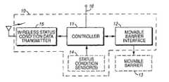
- a movable barrier operatorhas a controller having a plurality of potential operational status conditions, a movable barrier interface that operably couples to the controller, and a wireless status condition data transmitter that is operably coupled to the controller as well.
- one or more status condition sensorscan be utilized to sense one or more predetermined conditions and to provide corresponding indicia to the controller.
- the wireless status condition data transmittertransmits a status condition signal that corresponds to at least one of the potential operational status conditions.
- the status condition signalcan be combined with an identifier that correlates (uniquely or relatively uniquely) to the controller and/or the movable barrier operator. Such an identifier can serve to permit a receiving device to process as appropriate the status condition information.
- Such status condition informationcan be received and processed, in a preferred embodiment, by a remote peripheral device (such as, but not limited to, a display, an alarm, a lighting control unit, and so forth).
- a remote peripheral devicesuch as, but not limited to, a display, an alarm, a lighting control unit, and so forth.
- the remote peripheralcan be configured to process the data content to thereby nevertheless effect a desired corresponding action.
- a given movable barrier operatorcan be set to wirelessly transmit a wide variety of simple messages regarding its operational states. Such information can then be utilized to compatibly support a wide range of presently desired and later-developed features and functionality. If desired, the overall cost of a given platform can be reduced as the need to over-design a physical peripheral interface becomes diminished. Furthermore, such a platform has an improved opportunity to remain compatible with evolving features and legal and/or regulatory requirements to thereby promote a longer useful service life.
- a movable barrier operator 10will include a controller 11 , a movable barrier interface 12 , and a wireless status condition data transmitter 15 .
- the controller 11will preferably comprise a programmable platform (such as, for example, a microprocessor, a microcontroller, a programmable logic or gate array, or the like) that can be readily programmed and configured in accordance with the various teachings set forth herein and as is generally well understood in the art.
- the movable barrier interface 12couples to and is controlled by the controller 11 and further couples to a movable barrier 13 .
- the movable barrier interface 12serves to selectively impart motion to the movable barrier 13 to cause the movable barrier 13 to move to a desired position (such as, for example, a fully opened or a fully closed position) and/or to restrict or prohibit such motion (as when movement of the movable barrier may be the result of gravity and the movable barrier interface 12 serves in part to prevent such movement until such movement is desired).
- a desired positionsuch as, for example, a fully opened or a fully closed position
- the movable barrier interface 12serves in part to prevent such movement until such movement is desired.
- the wireless status condition data transmitter 15operably couples to an output of the controller 11 .
- This transmitter 15can be of any variety as may suit the needs of a given application.
- the transmitter 15can comprise a radio frequency carrier-based transmitter, an infrared carrier-based transmitter, or a sonic carrier-based transmitter (all being generally well understood in the art).
- the transmission power, modulation type, signaling protocol, and other attendant characterizing features and practices of the wireless transmitter 15can again be as desired to suit the needs of a particular setting.
- this transmitter 15will comprise a relatively low power transmitter such that the signals it broadcasts are only receivable within a relatively constrained area (such as, for example, an effective range of 100 meters, 500 meters, 1,000 meters, or the like). Again, such transmitters are well understood in the art and hence further elaboration here will not be provided.
- the controller 11will have a plurality of potential operational status conditions.
- the controller 11might have two or more of the following potential operational status conditions:
- the controller 11can be self-aware of such operational status conditions (as when, for example, the controller 11 is aware that it has switched a given ambient light fixture on or off) or the controller 11 can be provided with externally developed information regarding the condition. To effect the latter, it may be desirable in some settings to use one or more status condition sensors 14 .
- Such sensors 14can be disposed integral to the movable barrier operator 10 as suggested by the illustration in FIG. 1 and/or can be configured as remotely disposed entities to suit the requirements of a specific application.
- the wireless status condition data transmitter 15serves to transmit a status condition signal that represents a present operational status condition of the controller 11 .
- this transmissionoccurs automatically in response to when the controller 11 detects at least one predetermined condition, which predetermined condition preferably, but not necessarily, corresponds to the present operational status being reported via the transmission.
- Another optionwould be to have such information transmitted on a substantially regular periodic basis.
- An illustrative (but not all-inclusive) listing of potentially useful predetermined conditionsmight include:
- this status condition signaldoes not constitute a control signal per se. That is to say, the controller 11 does not necessarily source this status condition signal as a specific part of implementing a control strategy. As an example, the controller 11 would not source this status condition signal to specifically cause a light to be switched on upon receipt of the signal. Instead, the controller 11 sources this status condition signal to specify that it has, through some other means, initiated a control action or strategy to cause a light to be switched on. The status condition signal then simply reflects the actions being taken by the controller 11 and/or the other operational conditions being experienced by the controller 11 .
- such status condition data signalscan also be transmitted by the controller 11 via a wireline connection 16 .
- the status condition signals as transmitted from such a movable barrier operator 10are preferably received by a remote peripheral 20 having a corresponding compatible wireless receiver 21 that operably couples to a peripheral controller 22 .
- the remote peripheral 20itself can comprise any of a wide variety of platforms, including but certainly not limited to an informational display, a remote access interface, a light fixture, a timer apparatus, an alarm unit, and so forth. So configured, the remote peripheral 20 , upon receiving status condition information from the movable barrier operator 10 via the wireless transmissions being sourced by the latter, can process that information in accord with a desired end result. For example, the remote peripheral 20 can serve to simply further communicate such status information via a display such as an alphanumeric display, a graphic images display, one or more signal lights and/or corresponding indicative audible sounds, and so forth.
- the remote peripheral 20can process such status information to then itself ascertain a particular resultant course of activity.
- the remote peripheralcan comprise a peripheral lighting unit that controls the provision of ambient lighting in a particular area (such as in a yard area outside the entrance to a residential garage).
- the remote peripheral 20can then itself determine to also switch on its own lights.
- the remote peripheral 20can also decide to switch its own lights to an off condition.
- remote peripherals 20can be readily configured to leverage the receipt of such information for a variety of other purposes.
- Such remote peripheralscan further supplement or extend the functionality of the movable barrier operator 10 itself (as when the remote peripheral 20 simply activates additional lighting to complement the lighting strategy of the movable barrier operator 10 ) or they can facilitate functionality that is above and beyond the control architecture of the movable barrier operator 10 .
- the movable barrier operator 10tend towards a relatively rich data stream where at least many or even substantially all current operational status conditions are regularly noted and transmitted to thereby provide considerable informational grist for use by the remote peripherals to thereby more likely facilitate additional not-otherwise-supported functionality.
- the movable barrier operator 10serves as an appropriate platform to effect a process 30 wherein one or more predetermined operational status conditions are detected 31 .
- monitoringand/or condition occurrence sensitivity
- monitoringto support such detection occurs on a regular, or even substantially constant, basis.
- a plurality of operational status conditionsbe monitored such that a plurality of differing operational status conditions can be so detected as they occur.
- monitoring and detectioncan result through one or more operational status condition sensors and/or through the ability of the controller to self-monitor its own operational status.
- the process 30Upon detecting such a condition, the process 30 then forms 32 a message that includes content to relate, reflect, or otherwise correspond to the detected status condition.
- this messagecan be formed to include an identifier for the movable barrier operator.
- a message 40can include a first field 41 that includes a specific identification number that is at least relatively unique to a given movable barrier operator and that also includes one or more additional data fields.
- a single data fieldcan be used if desired to contain information that corresponds to the specified status condition.
- a plurality of fields(from field 1 41 to field N 43 ) can be provided, with each field corresponding to, for example, a particular monitored condition.
- the content of such fieldscould then comprise one or more flags or other indicia to indicate a particular present status for each such field.
- indiciacould also provide an indication as to an anticipated or planned change to the status of a given condition including, where available, an anticipated or planned temporal schedule for effecting such changes.
- a remote peripheralcan use the identifying information to determine whether the received information corresponds to a relevant movable barrier operator (i.e., to a movable barrier operator with which the remote peripheral has been previously associated).
- a relevant movable barrier operatori.e., to a movable barrier operator with which the remote peripheral has been previously associated.
- the process 30then provides for automatic transmission 33 of the status condition message via the carrier/transmitter of choice and as otherwise is generally described above. It would of course be possible to transmit other signals and messages via the transmitter too, if desired. For example, specific control signals could also be transmitted (either as part of the above-described message or as a separate message) as an integral part of the overall control strategy of the movable barrier operator.
- the above-described remote peripheral 20can serve as a suitable platform to effect a corresponding process 50 wherein the process 50 detects 51 for the reception of status condition signals and, upon receiving such a signal, uses the corresponding data to thereby permit effectuation 52 of a corresponding predetermined action.
- the corresponding predetermined actioncan be many and varied.
- a non-exhaustive illustrative listingcould include:
- the movable barrier operatorcould also wirelessly transmit control signaling in addition to the status condition information.
- control signalingmay not offer a same degree of long term flexibility as the preferred approaches set forth above, such control signaling may nevertheless serve to facilitate one or more presently known and highly desired features or functions.
- a remote peripheral controller 22can also couple to a wireless transmitter 62 .
- the movable barrier operator controller 11can further couple to a wireless receiver 61 that serves to compatibly receive messages as transmitted by the remote peripheral controller 11 .
- This linkcan mirror the carrier/modulation/protocol mechanism described above for the movable barrier operator-to-remote peripheral link, or it can be different.
- the movable barrier operatorcan have a wireless status condition data transmitter that uses an infrared carrier and a receiver that uses a radio frequency carrier. So configured, a variety of useful purposes can be served.
- the remote peripheral controller 22can query the movable barrier operator controller 11 via this communication mechanism to thereby cause the movable barrier operator controller 11 to respond with, for example, an updated status condition data message.
Landscapes
- Engineering & Computer Science (AREA)
- Computer Networks & Wireless Communication (AREA)
- Physics & Mathematics (AREA)
- General Physics & Mathematics (AREA)
- Selective Calling Equipment (AREA)
Abstract
Description
- moving the movable barrier in a first direction (such as towards a closed position);
- moving the movable barrier in a second direction (such as towards an opened position);
- reversing movement of the movable barrier (for example, to alter movement from a closed position and towards an open position);
- halting movement of the movable barrier;
- detecting a likely presence of an obstacle (such as a person or pet) in the likely path of movement of the movable barrier;
- detecting a likely proximal presence of a human (such as a person in the vicinity of the controller);
- detecting a likely proximal presence of a compatible transmitter (such as a corresponding remote control transmitter for the movable barrier operator);
- receiving a wireless remote control signal (as sourced, for example, by a handheld remote control device);
- receiving a wireline remote control signal (as sourced, for example, by a wall mounted remote control device);
- receiving a learning mode initiation signal (via, for example, a switch provided for this purpose on the movable barrier operator housing);
- a lighting status change (as when, for example, the controller switches ambient lighting in a garage to an off condition a predetermined period of time following closure of the movable barrier);
- a vacation mode status change (as when a user effects this change via a switch provided for this purpose);
- detecting a likely proximal presence of a vehicle;
- detecting the identification of a proximal vehicle (as when, for example, the vehicle or some corresponding agent device transmits an identifying signal); and
- receiving an operating parameter alteration signal (via, for example, an integral or remote switch or other user interface).
It will be understood and appreciated that these are intended for illustrative purposes only, and that a given controller may have only a subset of these status conditions, a combination of some or all of these status conditions with other status conditions, or a set of wholly different potential status conditions.
- moving the movable barrier in a first direction;
- moving the movable barrier in a second direction;
- reversing movement of the movable barrier;
- halting movement of the movable barrier;
- detecting a likely presence of an obstacle to movement of the movable barrier;
- detecting a likely proximal presence of a human;
- receiving a wireless remote control signal;
- receiving a wireline remote control signal;
- receiving a learning mode initiation signal;
- receiving an operating parameter alteration signal;
- expiration of a predetermined duration of time; and
- attainment of a predetermined point in time.
- activating a light (either ambient lighting and/or signaling indicia);
- deactivating a light;
- activating an audible alarm;
- deactivating an audible alarm;
- manipulating a locking mechanism;
- providing a corresponding information display;
- allowing remote modification of configuration variables; and
- initiating a timing mechanism.
Other possibilities of course exist. It should also be clearly understood that functions not yet conceived or enabled may also be well served and supported by these embodiments, as these embodiments are not dependent upon the movable barrier operator having an already-existing native ability to support such functionality. Instead, by providing movable barrier operator status indicia, the remote peripherals are themselves able to intuit when circumstances are appropriate to initiate or restrain their own functionality and features.
Claims (31)
Priority Applications (7)
| Application Number | Priority Date | Filing Date | Title |
|---|---|---|---|
| US10/447,663US7224275B2 (en) | 2003-05-29 | 2003-05-29 | Movable barrier operators status condition transception apparatus and method |
| CA2468493ACA2468493C (en) | 2003-05-29 | 2004-05-26 | Movable barrier operator status condition transception apparatus and method |
| AU2004202319AAU2004202319A1 (en) | 2003-05-29 | 2004-05-27 | Movable Barrier Operator Status Condition Transception Apparatus and Method |
| FR0405741AFR2855546A1 (en) | 2003-05-29 | 2004-05-27 | APPARATUS AND METHOD FOR TRANSMITTING AND RECEIVING A CONDITION OF CONDITION OF A MOBILE BARRIER ACTUATOR |
| DE102004025889ADE102004025889A1 (en) | 2003-05-29 | 2004-05-27 | A status-state transfer device and method for a movable-barrier operator |
| GB0412067AGB2402434B (en) | 2003-05-29 | 2004-05-28 | Movable barrier operator status condition transception apparatus and method |
| MXPA04005149AMXPA04005149A (en) | 2003-05-29 | 2004-05-28 | Movable barrier operators status condition transception apparatus and method. |
Applications Claiming Priority (1)
| Application Number | Priority Date | Filing Date | Title |
|---|---|---|---|
| US10/447,663US7224275B2 (en) | 2003-05-29 | 2003-05-29 | Movable barrier operators status condition transception apparatus and method |
Publications (2)
| Publication Number | Publication Date |
|---|---|
| US20040239496A1 US20040239496A1 (en) | 2004-12-02 |
| US7224275B2true US7224275B2 (en) | 2007-05-29 |
Family
ID=32682480
Family Applications (1)
| Application Number | Title | Priority Date | Filing Date |
|---|---|---|---|
| US10/447,663Expired - LifetimeUS7224275B2 (en) | 2003-05-29 | 2003-05-29 | Movable barrier operators status condition transception apparatus and method |
Country Status (7)
| Country | Link |
|---|---|
| US (1) | US7224275B2 (en) |
| AU (1) | AU2004202319A1 (en) |
| CA (1) | CA2468493C (en) |
| DE (1) | DE102004025889A1 (en) |
| FR (1) | FR2855546A1 (en) |
| GB (1) | GB2402434B (en) |
| MX (1) | MXPA04005149A (en) |
Cited By (19)
| Publication number | Priority date | Publication date | Assignee | Title |
|---|---|---|---|---|
| US20060026520A1 (en)* | 2004-07-29 | 2006-02-02 | The Chamberlain Group, Inc. | Movable barrier operator operating parameter transfer method and apparatus |
| US20080186129A1 (en)* | 2007-02-01 | 2008-08-07 | The Chamberlain Group, Inc. | Method and Apparatus to Facilitate Providing Power to Remote Peripheral Devices for Use with A Movable Barrier Operator System |
| US20090224877A1 (en)* | 2008-03-04 | 2009-09-10 | Siren Operated Sensors, Inc. | System and method for radio controlled gate and gate status |
| US20100242368A1 (en)* | 2008-04-02 | 2010-09-30 | Leon Yulkowski | Electrical door operator |
| US20110016971A1 (en)* | 2009-07-21 | 2011-01-27 | Openings, Lp | Door monitoring system |
| US8922356B2 (en) | 2011-12-13 | 2014-12-30 | General Motors Llc | Entryway control and monitoring system |
| US20150059989A1 (en)* | 2013-08-27 | 2015-03-05 | Herman Gutierrez | Overhead door spring alert safety system |
| US9507335B2 (en) | 2012-05-31 | 2016-11-29 | Overhead Door Corporation | Remote barrier operator command and status device and operation |
| US9978265B2 (en) | 2016-04-11 | 2018-05-22 | Tti (Macao Commercial Offshore) Limited | Modular garage door opener |
| US10096187B2 (en) | 2015-04-09 | 2018-10-09 | Overhead Door Corporation | Automatic transmission of a barrier status and change of status over a network |
| US10221609B2 (en) | 2008-04-02 | 2019-03-05 | Leon Yulkowski | Concealed electrical door operator |
| US10378262B2 (en) | 2014-10-23 | 2019-08-13 | Leon Yulkowski | Door operator and clutch |
| US10540889B2 (en) | 2017-05-12 | 2020-01-21 | Gmi Holdings, Inc. | Remote monitoring and control of movable barrier status |
| US10633907B2 (en) | 2017-06-06 | 2020-04-28 | Gto Access Systems, Llc | Edge sensor for movable barrier |
| US10689898B2 (en) | 2017-06-22 | 2020-06-23 | Wichita State University | Internet-based remote control and monitoring system for commercial doors using mobile devices |
| US11361604B1 (en) | 2012-06-12 | 2022-06-14 | Gmi Holdings, Inc. | Garage door system and method |
| US11393331B2 (en) | 2017-05-12 | 2022-07-19 | Gmi Holdings, Inc. | Remote monitoring and control of movable barrier status |
| US11746584B2 (en) | 2019-04-24 | 2023-09-05 | Gmi Holdings, Inc. | Remote monitoring and control of moveable barrier in jackshaft door operator system |
| US11928953B2 (en) | 2020-01-23 | 2024-03-12 | ASSA ABLOY Residential Group, Inc. | Garage door opener maintenance and services |
Families Citing this family (30)
| Publication number | Priority date | Publication date | Assignee | Title |
|---|---|---|---|---|
| GB0325900D0 (en)* | 2003-11-06 | 2003-12-10 | Kingpin Bollards Ltd | Barrier system |
| US7397342B2 (en)* | 2004-02-19 | 2008-07-08 | Wayne-Dalton Corp. | Operating system for a motorized barrier operator with a radio frequency energized light kit and/or switch and methods for programming the same |
| US7750890B2 (en)* | 2004-05-11 | 2010-07-06 | The Chamberlain Group, Inc. | Movable barrier operator system display method and apparatus |
| US8494861B2 (en) | 2004-05-11 | 2013-07-23 | The Chamberlain Group, Inc. | Movable barrier control system component with audible speech output apparatus and method |
| US7266344B2 (en)* | 2004-06-02 | 2007-09-04 | Wayne-Dalton Corp. | Remotely activated bridge device for use with a home network and methods for programming and using the same |
| US20060103503A1 (en)* | 2004-11-12 | 2006-05-18 | Yan Rodriguez | Networked movable barrier operator system |
| US8542093B2 (en)* | 2004-11-12 | 2013-09-24 | Qmotion Incorporated | Networked movable barrier operator system |
| US7853221B2 (en)* | 2004-11-12 | 2010-12-14 | Homerun Holdings Corp. | Network bridge device and methods for programming and using the same |
| US7956718B2 (en)* | 2004-12-16 | 2011-06-07 | Overhead Door Corporation | Remote control and monitoring of barrier operators with radio frequency transceivers |
| US20080012682A1 (en)* | 2006-02-06 | 2008-01-17 | Fraba Ag | Wireless controller for monitoring device |
| US8014966B2 (en) | 2006-06-23 | 2011-09-06 | Overhead Door Corporation | Calibration and setup unit for barrier operator control system |
| US20080061948A1 (en)* | 2006-08-18 | 2008-03-13 | Daniel Perez | System and method for communicating with gate operators via a power line |
| US20080094186A1 (en)* | 2006-10-04 | 2008-04-24 | Viking Access Systems, Llc | Apparatus and method for monitoring and controlling gate operators via power line communication |
| US20080106370A1 (en)* | 2006-11-02 | 2008-05-08 | Viking Access Systems, Llc | System and method for speech-recognition facilitated communication to monitor and control access to premises |
| US20080224819A1 (en)* | 2007-03-16 | 2008-09-18 | The Chamberlain Group, Inc. | Multiple barrier operator system |
| US20090085719A1 (en)* | 2007-09-28 | 2009-04-02 | Daniel Perez | System and method for monitoring and controlling a movable barrier operator utilizing satellite communication capabilities |
| US20090188166A1 (en)* | 2008-01-24 | 2009-07-30 | Hassan Taheri | System for gearless operation of a movable barrier utilizing lorentz forces |
| US7816875B2 (en)* | 2008-01-24 | 2010-10-19 | Viking Access Systems, Llc | High torque gearless actuation at low speeds for swing gate, roll-up gate, slide gate, and vehicular barrier operators |
| US7816879B2 (en)* | 2008-02-19 | 2010-10-19 | Viking Access Systems, Llc | High torque movable barrier actuation at low speeds utilizing a hub motor |
| US20090211160A1 (en)* | 2008-02-26 | 2009-08-27 | Ali Tehranchi | Access device with a photovoltaic housing utilized to generate power |
| IT1396494B1 (en)* | 2009-02-23 | 2012-12-14 | Rib Srl | SIGNALING DEVICE PARTICULARLY FOR AUTOMATIC OPENING / CLOSING SYSTEMS |
| US8760265B2 (en)* | 2009-05-08 | 2014-06-24 | Apple Inc. | Remote control signal learning and processing by a host device and accessory |
| US20100289616A1 (en)* | 2009-05-18 | 2010-11-18 | Ali Tehranchi | Movable barrier system adapted to utilize biometric technology to identify and authorize access to premises |
| US9890575B2 (en) | 2013-12-09 | 2018-02-13 | Viking Access Systems, Llc | Movable barrier operator with removable power supply module |
| WO2017200914A1 (en)* | 2016-05-16 | 2017-11-23 | Schlage Lock Company Llc | Door closer communication |
| CN105974846B (en)* | 2016-06-24 | 2024-04-02 | 东北大学 | Remotely controllable movable guardrail system and control method thereof |
| AU2017248531A1 (en)* | 2016-10-20 | 2018-05-10 | Tti (Macao Commercial Offshore) Limited | Systems and methods for diagnostics to support operation of a garage door opener using asynchronous reporting of logged data |
| US9909351B1 (en) | 2017-03-17 | 2018-03-06 | Tti (Macao Commercial Offshore) Limited | Garage door opener system and method of operating a garage door opener system |
| CN107974969A (en)* | 2017-11-21 | 2018-05-01 | 浙江工业大学 | A kind of tide track altering system and method based on electronic compass |
| CN109235320B (en)* | 2018-10-26 | 2022-03-01 | 北京小米移动软件有限公司 | Barrier control method and device |
Citations (30)
| Publication number | Priority date | Publication date | Assignee | Title |
|---|---|---|---|---|
| US3611333A (en) | 1969-01-29 | 1971-10-05 | Nicholas Conigliaro | Mailbox operated electronic signal device |
| US3827038A (en) | 1972-10-26 | 1974-07-30 | Solid State Technology | Alarm system |
| US3831158A (en) | 1973-04-30 | 1974-08-20 | R Rempel | Self-levelling motion detecting device and alarm system incorporating the same |
| US3833895A (en)* | 1972-12-29 | 1974-09-03 | D Fecteau | Intrusion alarm with indication of prior activation |
| US4074269A (en) | 1976-06-16 | 1978-02-14 | Justin Hartley | Burglar alarm for use with an automatic garage door opener |
| US4090182A (en) | 1976-03-22 | 1978-05-16 | Robert Bruno Young | Security system employing radio transmitter and receiver |
| US4124847A (en) | 1977-04-20 | 1978-11-07 | Cashman Richard D | Door alarm system |
| US4464651A (en)* | 1980-04-14 | 1984-08-07 | Stanley Vemco | Home security and garage door operator system |
| US4536751A (en) | 1982-06-30 | 1985-08-20 | Secom Co., Ltd. | System for detecting an alarm |
| US4583081A (en) | 1983-12-30 | 1986-04-15 | Motorola, Inc. | Status indicator system for a radio-controlled door operator |
| US4750118A (en) | 1985-10-29 | 1988-06-07 | Chamberlain Manufacturing Corporation | Coding system for multiple transmitters and a single receiver for a garage door opener |
| US4819379A (en) | 1987-03-06 | 1989-04-11 | Automatic Electrolock, Inc. | Electromagnetic garage door locking apparatus |
| US4868543A (en) | 1986-12-12 | 1989-09-19 | Synpac Corporation | Remote mailbox alarm system |
| US4872210A (en) | 1988-03-25 | 1989-10-03 | Alexander Benages | Curbside mailbox signal |
| US4905279A (en) | 1988-02-26 | 1990-02-27 | Nec Home Electronics Ltd. | Learning-functionalized remote control receiver |
| US4954810A (en) | 1990-01-22 | 1990-09-04 | Llewellyn Theodore E | Garage door openers |
| US5402105A (en)* | 1992-06-08 | 1995-03-28 | Mapa Corporation | Garage door position indicating system |
| US5635913A (en) | 1990-07-16 | 1997-06-03 | The Chamberlain Group, Inc. | Remote actuating apparatus with long and short operating codes |
| US5798681A (en)* | 1995-09-06 | 1998-08-25 | Chang; Nai-Wen | Garage door position indicator |
| US5903226A (en)* | 1993-03-15 | 1999-05-11 | Prince Corporation | Trainable RF system for remotely controlling household appliances |
| US6025785A (en) | 1996-04-24 | 2000-02-15 | The Chamberlain Group, Inc. | Multiple code formats in a single garage door opener including at least one fixed code format and at least one rolling code format |
| US6049289A (en) | 1996-09-06 | 2000-04-11 | Overhead Door Corporation | Remote controlled garage door opening system |
| US6070361A (en) | 1997-12-09 | 2000-06-06 | Paterno; Robert S. | Garage door operating system and method of operating a garage door |
| US6184787B1 (en)* | 1998-06-04 | 2001-02-06 | Duane A. Morris | Overhead garage door position monitoring system |
| US6218956B1 (en)* | 1996-08-28 | 2001-04-17 | The Chamberlain Group, Inc. | Gate operator with remote diagnostic capability |
| US6346889B1 (en) | 2000-07-01 | 2002-02-12 | Richard D. Moss | Security system for automatic door |
| US20020180600A1 (en)* | 2001-05-29 | 2002-12-05 | Kirkland Ronnie L. | Garage door remote monitoring system |
| US20030029579A1 (en) | 2001-07-10 | 2003-02-13 | Overhead Door Corporation | Automatic barrier operator system |
| US20030076235A1 (en) | 2001-10-10 | 2003-04-24 | Tsui Gallen Ka Leung | Garage door monitoring system |
| US20040212498A1 (en)* | 2003-04-28 | 2004-10-28 | The Chamberlain Group, Inc. | Barrier movement arrangement human interface method and apparatus |
- 2003
- 2003-05-29USUS10/447,663patent/US7224275B2/ennot_activeExpired - Lifetime
- 2004
- 2004-05-26CACA2468493Apatent/CA2468493C/ennot_activeExpired - Lifetime
- 2004-05-27DEDE102004025889Apatent/DE102004025889A1/ennot_activeWithdrawn
- 2004-05-27AUAU2004202319Apatent/AU2004202319A1/ennot_activeAbandoned
- 2004-05-27FRFR0405741Apatent/FR2855546A1/ennot_activeWithdrawn
- 2004-05-28MXMXPA04005149Apatent/MXPA04005149A/ennot_activeApplication Discontinuation
- 2004-05-28GBGB0412067Apatent/GB2402434B/ennot_activeExpired - Fee Related
Patent Citations (31)
| Publication number | Priority date | Publication date | Assignee | Title |
|---|---|---|---|---|
| US3611333A (en) | 1969-01-29 | 1971-10-05 | Nicholas Conigliaro | Mailbox operated electronic signal device |
| US3827038A (en) | 1972-10-26 | 1974-07-30 | Solid State Technology | Alarm system |
| US3833895A (en)* | 1972-12-29 | 1974-09-03 | D Fecteau | Intrusion alarm with indication of prior activation |
| US3831158A (en) | 1973-04-30 | 1974-08-20 | R Rempel | Self-levelling motion detecting device and alarm system incorporating the same |
| US4090182A (en) | 1976-03-22 | 1978-05-16 | Robert Bruno Young | Security system employing radio transmitter and receiver |
| US4074269A (en) | 1976-06-16 | 1978-02-14 | Justin Hartley | Burglar alarm for use with an automatic garage door opener |
| US4124847A (en) | 1977-04-20 | 1978-11-07 | Cashman Richard D | Door alarm system |
| US4464651A (en)* | 1980-04-14 | 1984-08-07 | Stanley Vemco | Home security and garage door operator system |
| US4536751A (en) | 1982-06-30 | 1985-08-20 | Secom Co., Ltd. | System for detecting an alarm |
| US4583081A (en) | 1983-12-30 | 1986-04-15 | Motorola, Inc. | Status indicator system for a radio-controlled door operator |
| US4750118A (en) | 1985-10-29 | 1988-06-07 | Chamberlain Manufacturing Corporation | Coding system for multiple transmitters and a single receiver for a garage door opener |
| US4868543A (en) | 1986-12-12 | 1989-09-19 | Synpac Corporation | Remote mailbox alarm system |
| US4819379A (en) | 1987-03-06 | 1989-04-11 | Automatic Electrolock, Inc. | Electromagnetic garage door locking apparatus |
| US4905279A (en) | 1988-02-26 | 1990-02-27 | Nec Home Electronics Ltd. | Learning-functionalized remote control receiver |
| US4872210A (en) | 1988-03-25 | 1989-10-03 | Alexander Benages | Curbside mailbox signal |
| US4954810A (en) | 1990-01-22 | 1990-09-04 | Llewellyn Theodore E | Garage door openers |
| US5635913A (en) | 1990-07-16 | 1997-06-03 | The Chamberlain Group, Inc. | Remote actuating apparatus with long and short operating codes |
| US5402105A (en)* | 1992-06-08 | 1995-03-28 | Mapa Corporation | Garage door position indicating system |
| US5903226A (en)* | 1993-03-15 | 1999-05-11 | Prince Corporation | Trainable RF system for remotely controlling household appliances |
| US5798681A (en)* | 1995-09-06 | 1998-08-25 | Chang; Nai-Wen | Garage door position indicator |
| US6025785A (en) | 1996-04-24 | 2000-02-15 | The Chamberlain Group, Inc. | Multiple code formats in a single garage door opener including at least one fixed code format and at least one rolling code format |
| US6218956B1 (en)* | 1996-08-28 | 2001-04-17 | The Chamberlain Group, Inc. | Gate operator with remote diagnostic capability |
| US6049289A (en) | 1996-09-06 | 2000-04-11 | Overhead Door Corporation | Remote controlled garage door opening system |
| US6070361A (en) | 1997-12-09 | 2000-06-06 | Paterno; Robert S. | Garage door operating system and method of operating a garage door |
| US6184787B1 (en)* | 1998-06-04 | 2001-02-06 | Duane A. Morris | Overhead garage door position monitoring system |
| US6346889B1 (en) | 2000-07-01 | 2002-02-12 | Richard D. Moss | Security system for automatic door |
| US20020180600A1 (en)* | 2001-05-29 | 2002-12-05 | Kirkland Ronnie L. | Garage door remote monitoring system |
| US20030029579A1 (en) | 2001-07-10 | 2003-02-13 | Overhead Door Corporation | Automatic barrier operator system |
| US20030076235A1 (en) | 2001-10-10 | 2003-04-24 | Tsui Gallen Ka Leung | Garage door monitoring system |
| US6597291B2 (en)* | 2001-10-10 | 2003-07-22 | Gallen Ka Leung Tsui | Garage door monitoring system |
| US20040212498A1 (en)* | 2003-04-28 | 2004-10-28 | The Chamberlain Group, Inc. | Barrier movement arrangement human interface method and apparatus |
Non-Patent Citations (2)
| Title |
|---|
| British Search Report for British patent application GB0412067.1 dated Oct. 4, 2004. |
| U.S. Appl. No. 10/226,854, filed Aug. 23, 2002, Doyle. |
Cited By (39)
| Publication number | Priority date | Publication date | Assignee | Title |
|---|---|---|---|---|
| US20060026520A1 (en)* | 2004-07-29 | 2006-02-02 | The Chamberlain Group, Inc. | Movable barrier operator operating parameter transfer method and apparatus |
| US7724126B2 (en)* | 2004-07-29 | 2010-05-25 | The Chamberlain Group, Inc. | Movable barrier operator operating parameter transfer method and apparatus |
| US20080186129A1 (en)* | 2007-02-01 | 2008-08-07 | The Chamberlain Group, Inc. | Method and Apparatus to Facilitate Providing Power to Remote Peripheral Devices for Use with A Movable Barrier Operator System |
| US9143009B2 (en)* | 2007-02-01 | 2015-09-22 | The Chamberlain Group, Inc. | Method and apparatus to facilitate providing power to remote peripheral devices for use with a movable barrier operator system |
| US20090224877A1 (en)* | 2008-03-04 | 2009-09-10 | Siren Operated Sensors, Inc. | System and method for radio controlled gate and gate status |
| US11199041B2 (en) | 2008-04-02 | 2021-12-14 | Td Ip Holdco, Llc | Concealed electrical door operator |
| US8844200B2 (en) | 2008-04-02 | 2014-09-30 | Globe Motors, Inc. | Electrical door operator |
| US20100242368A1 (en)* | 2008-04-02 | 2010-09-30 | Leon Yulkowski | Electrical door operator |
| US10221609B2 (en) | 2008-04-02 | 2019-03-05 | Leon Yulkowski | Concealed electrical door operator |
| US8653982B2 (en) | 2009-07-21 | 2014-02-18 | Openings | Door monitoring system |
| US8907791B2 (en) | 2009-07-21 | 2014-12-09 | Td Ip Holdco, Llc | Door monitoring system |
| US20110016971A1 (en)* | 2009-07-21 | 2011-01-27 | Openings, Lp | Door monitoring system |
| US11713608B2 (en) | 2009-07-21 | 2023-08-01 | Td Ip Holdco, Llc | Door monitoring system |
| US9536357B2 (en) | 2009-07-21 | 2017-01-03 | Td Ip Holdco, Llc | Door monitoring system |
| US11028630B2 (en) | 2009-07-21 | 2021-06-08 | Td Ip Holdco, Llc | Door monitoring system |
| US10415294B2 (en) | 2009-07-21 | 2019-09-17 | Td Ip Holdco, Llc | Door monitoring system |
| US10024096B2 (en) | 2009-07-21 | 2018-07-17 | Tp Ip Holdco, Llc | Door monitoring system |
| US8922356B2 (en) | 2011-12-13 | 2014-12-30 | General Motors Llc | Entryway control and monitoring system |
| US9870664B2 (en) | 2012-05-31 | 2018-01-16 | Overhead Door Corporation | Remote barrier operator command and status device and operation |
| US9507335B2 (en) | 2012-05-31 | 2016-11-29 | Overhead Door Corporation | Remote barrier operator command and status device and operation |
| US12072680B2 (en) | 2012-06-12 | 2024-08-27 | Gmi Holdings, Inc. | Garage door system and method |
| US12038730B2 (en) | 2012-06-12 | 2024-07-16 | Gmi Holdings, Inc. | Garage door system and method |
| US11361604B1 (en) | 2012-06-12 | 2022-06-14 | Gmi Holdings, Inc. | Garage door system and method |
| US20150059989A1 (en)* | 2013-08-27 | 2015-03-05 | Herman Gutierrez | Overhead door spring alert safety system |
| US11098517B2 (en) | 2014-10-23 | 2021-08-24 | Td Ip Holdco, Llc | Door operator and clutch |
| US10378262B2 (en) | 2014-10-23 | 2019-08-13 | Leon Yulkowski | Door operator and clutch |
| US10614647B2 (en) | 2015-04-09 | 2020-04-07 | Overhead Door Corporation | Remote transmission of barrier status and change of status over a network |
| US10096187B2 (en) | 2015-04-09 | 2018-10-09 | Overhead Door Corporation | Automatic transmission of a barrier status and change of status over a network |
| US10157538B2 (en) | 2016-04-11 | 2018-12-18 | Tti (Macao Commercial Offshore) Limited | Modular garage door opener |
| US10127806B2 (en) | 2016-04-11 | 2018-11-13 | Tti (Macao Commercial Offshore) Limited | Methods and systems for controlling a garage door opener accessory |
| US9978265B2 (en) | 2016-04-11 | 2018-05-22 | Tti (Macao Commercial Offshore) Limited | Modular garage door opener |
| US11393331B2 (en) | 2017-05-12 | 2022-07-19 | Gmi Holdings, Inc. | Remote monitoring and control of movable barrier status |
| US20220351611A1 (en)* | 2017-05-12 | 2022-11-03 | Gmi Holdings, Inc. | Remote monitoring and control of movable barrier status |
| US10540889B2 (en) | 2017-05-12 | 2020-01-21 | Gmi Holdings, Inc. | Remote monitoring and control of movable barrier status |
| US12125372B2 (en)* | 2017-05-12 | 2024-10-22 | Gmi Holdings, Inc. | Remote monitoring and control of movable barrier status |
| US10633907B2 (en) | 2017-06-06 | 2020-04-28 | Gto Access Systems, Llc | Edge sensor for movable barrier |
| US10689898B2 (en) | 2017-06-22 | 2020-06-23 | Wichita State University | Internet-based remote control and monitoring system for commercial doors using mobile devices |
| US11746584B2 (en) | 2019-04-24 | 2023-09-05 | Gmi Holdings, Inc. | Remote monitoring and control of moveable barrier in jackshaft door operator system |
| US11928953B2 (en) | 2020-01-23 | 2024-03-12 | ASSA ABLOY Residential Group, Inc. | Garage door opener maintenance and services |
Also Published As
| Publication number | Publication date |
|---|---|
| GB2402434A (en) | 2004-12-08 |
| FR2855546A1 (en) | 2004-12-03 |
| MXPA04005149A (en) | 2005-04-28 |
| CA2468493C (en) | 2012-01-03 |
| AU2004202319A1 (en) | 2004-12-16 |
| GB2402434B (en) | 2006-12-20 |
| US20040239496A1 (en) | 2004-12-02 |
| GB0412067D0 (en) | 2004-06-30 |
| DE102004025889A1 (en) | 2005-01-05 |
| CA2468493A1 (en) | 2004-11-29 |
Similar Documents
| Publication | Publication Date | Title |
|---|---|---|
| US7224275B2 (en) | Movable barrier operators status condition transception apparatus and method | |
| CA2468612C (en) | Status signal method and apparatus for movable barrier operator and corresponding wireless remote control | |
| US8058970B2 (en) | System and methods for automatically moving access barriers initiated by mobile transmitter devices | |
| CA2464877C (en) | Barrier movement operator human interface method and apparatus | |
| US9818243B2 (en) | System interaction with a movable barrier operator method and apparatus | |
| US7375484B2 (en) | System and method for unattended control of an access barrier | |
| CA2612209C (en) | Network id activated transmitter | |
| AU2004201551A1 (en) | Barrier Movement Operator Including Timer to Close Feature | |
| US20040107639A1 (en) | System and related methods for signaling the position of a movable barrier and securing its position | |
| MXPA04011356A (en) | Barrier movement operator having service reminders. | |
| US7211975B2 (en) | Motorized barrier operator system adaptable to different safety configurations and methods for programming the same | |
| JP2000265763A (en) | Electric shutter device | |
| JP2003324498A (en) | Wireless transmitting / receiving system and opening / closing device for building opening | |
| GB2425848A (en) | A controller for a barrier | |
| KR20030038985A (en) | Active sunroof control and warning system |
Legal Events
| Date | Code | Title | Description |
|---|---|---|---|
| AS | Assignment | Owner name:CHAMBERLAIN GROUP, INC., THE, ILLINOIS Free format text:ASSIGNMENT OF ASSIGNORS INTEREST;ASSIGNOR:FITZGIBBON, JAMES;REEL/FRAME:014573/0526 Effective date:20030819 | |
| STCF | Information on status: patent grant | Free format text:PATENTED CASE | |
| FPAY | Fee payment | Year of fee payment:4 | |
| FPAY | Fee payment | Year of fee payment:8 | |
| IPR | Aia trial proceeding filed before the patent and appeal board: inter partes review | Free format text:TRIAL NO: IPR2016-01772 Opponent name:ONE WORLD TECHNOLOGIES, INC. D/B/A TECHTRONIC INDU Effective date:20160909 Free format text:TRIAL NO: IPR2016-01774 Opponent name:ONE WORLD TECHNOLOGIES, INC. D/B/A TECHTRONIC INDU Effective date:20160909 | |
| IPR | Aia trial proceeding filed before the patent and appeal board: inter partes review | Free format text:TRIAL NO: IPR2017-01546 Opponent name:ONE WORLD TECHNOLOGIES, INC. D/B/A TECHTRONIC INDU Effective date:20170612 | |
| MAFP | Maintenance fee payment | Free format text:PAYMENT OF MAINTENANCE FEE, 12TH YEAR, LARGE ENTITY (ORIGINAL EVENT CODE: M1553); ENTITY STATUS OF PATENT OWNER: LARGE ENTITY Year of fee payment:12 | |
| AS | Assignment | Owner name:ARES CAPITAL CORPORATION, AS COLLATERAL AGENT, NEW YORK Free format text:SECOND LIEN PATENT SECURITY AGREEMENT;ASSIGNORS:THE CHAMBERLAIN GROUP LLC;SYSTEMS, LLC;REEL/FRAME:058015/0001 Effective date:20211103 Owner name:WELLS FARGO BANK, NATIONAL ASSOCIATION, AS COLLATERAL AGENT, COLORADO Free format text:FIRST LIEN PATENT SECURITY AGREEMENT;ASSIGNORS:THE CHAMBERLAIN GROUP LLC;SYSTEMS, LLC;REEL/FRAME:058014/0931 Effective date:20211103 | |
| AS | Assignment | Owner name:THE CHAMBLERLAIN GROUP LLC, ILLINOIS Free format text:CONVERSION;ASSIGNOR:THE CHAMBERLAIN GROUP, INC.;REEL/FRAME:058738/0305 Effective date:20210805 | |
| AS | Assignment | Owner name:THE CHAMBERLAIN GROUP LLC, ILLINOIS Free format text:CONVERSION;ASSIGNOR:THE CHAMBERLAIN GROUP, INC.;REEL/FRAME:060379/0207 Effective date:20210805 | |
| AS | Assignment | Owner name:SYSTEMS, LLC, ILLINOIS Free format text:NOTICE OF TERMINATION AND RELEASE OF SECURITY INTEREST IN PATENTS;ASSIGNOR:ARES CAPITAL CORPORATION, AS COLLATERAL AGENT;REEL/FRAME:066374/0749 Effective date:20240126 Owner name:THE CHAMBERLAIN GROUP LLC, ILLINOIS Free format text:NOTICE OF TERMINATION AND RELEASE OF SECURITY INTEREST IN PATENTS;ASSIGNOR:ARES CAPITAL CORPORATION, AS COLLATERAL AGENT;REEL/FRAME:066374/0749 Effective date:20240126 |