US7224272B2 - Power line repeater system and method - Google Patents
Power line repeater system and methodDownload PDFInfo
- Publication number
- US7224272B2 US7224272B2US11/091,677US9167705AUS7224272B2US 7224272 B2US7224272 B2US 7224272B2US 9167705 AUS9167705 AUS 9167705AUS 7224272 B2US7224272 B2US 7224272B2
- Authority
- US
- United States
- Prior art keywords
- data
- power line
- modem
- address
- voltage power
- Prior art date
- Legal status (The legal status is an assumption and is not a legal conclusion. Google has not performed a legal analysis and makes no representation as to the accuracy of the status listed.)
- Expired - Lifetime, expires
Links
- 238000000034methodMethods0.000titleclaimsdescription56
- 230000006854communicationEffects0.000claimsabstractdescription171
- 238000004891communicationMethods0.000claimsabstractdescription171
- 238000011144upstream manufacturingMethods0.000claimsabstractdescription31
- 238000012545processingMethods0.000claimsabstractdescription26
- 230000004044responseEffects0.000claimsdescription55
- 230000007704transitionEffects0.000claimsdescription3
- 230000005540biological transmissionEffects0.000abstractdescription47
- 239000004020conductorSubstances0.000description47
- 238000009826distributionMethods0.000description41
- 238000005259measurementMethods0.000description32
- 230000006870functionEffects0.000description22
- 108091006146ChannelsProteins0.000description16
- 230000004913activationEffects0.000description16
- 238000001994activationMethods0.000description16
- 238000001914filtrationMethods0.000description13
- 230000008859changeEffects0.000description12
- 238000009434installationMethods0.000description12
- 230000008569processEffects0.000description12
- 239000000835fiberSubstances0.000description10
- 230000008878couplingEffects0.000description9
- 238000010168coupling processMethods0.000description9
- 238000005859coupling reactionMethods0.000description9
- 238000001514detection methodMethods0.000description9
- 238000012544monitoring processMethods0.000description9
- 230000007935neutral effectEffects0.000description9
- 239000003990capacitorSubstances0.000description8
- 238000001907polarising light microscopyMethods0.000description8
- 238000013519translationMethods0.000description8
- 238000003860storageMethods0.000description7
- 238000007726management methodMethods0.000description6
- 230000003068static effectEffects0.000description6
- 230000003750conditioning effectEffects0.000description5
- 238000010586diagramMethods0.000description5
- 230000008901benefitEffects0.000description4
- 239000000872bufferSubstances0.000description4
- VNWKTOKETHGBQD-UHFFFAOYSA-NmethaneChemical compoundCVNWKTOKETHGBQD-UHFFFAOYSA-N0.000description4
- 230000002093peripheral effectEffects0.000description4
- 239000000523sampleSubstances0.000description4
- 239000000779smokeSubstances0.000description4
- XLYOFNOQVPJJNP-UHFFFAOYSA-NwaterSubstancesOXLYOFNOQVPJJNP-UHFFFAOYSA-N0.000description4
- 239000007789gasSubstances0.000description3
- 230000001939inductive effectEffects0.000description3
- OJLOPKGSLYJEMD-URPKTTJQSA-Nmethyl 7-[(1r,2r,3r)-3-hydroxy-2-[(1e)-4-hydroxy-4-methyloct-1-en-1-yl]-5-oxocyclopentyl]heptanoateChemical compoundCCCCC(C)(O)C\C=C\[C@H]1[C@H](O)CC(=O)[C@@H]1CCCCCCC(=O)OCOJLOPKGSLYJEMD-URPKTTJQSA-N0.000description3
- 230000004048modificationEffects0.000description3
- 238000012986modificationMethods0.000description3
- 230000037361pathwayEffects0.000description3
- 238000013439planningMethods0.000description3
- 238000012913prioritisationMethods0.000description3
- 238000012384transportation and deliveryMethods0.000description3
- UGFAIRIUMAVXCW-UHFFFAOYSA-NCarbon monoxideChemical compound[O+]#[C-]UGFAIRIUMAVXCW-UHFFFAOYSA-N0.000description2
- 241001165050OcalaSpecies0.000description2
- 230000002776aggregationEffects0.000description2
- 238000004220aggregationMethods0.000description2
- 230000007175bidirectional communicationEffects0.000description2
- 229910002091carbon monoxideInorganic materials0.000description2
- 238000006243chemical reactionMethods0.000description2
- 230000001934delayEffects0.000description2
- 238000011161developmentMethods0.000description2
- 230000000977initiatory effectEffects0.000description2
- 230000007246mechanismEffects0.000description2
- 239000003345natural gasSubstances0.000description2
- 230000000737periodic effectEffects0.000description2
- 238000010248power generationMethods0.000description2
- 230000008439repair processEffects0.000description2
- 238000005070samplingMethods0.000description2
- 230000001629suppressionEffects0.000description2
- 238000012360testing methodMethods0.000description2
- 238000012546transferMethods0.000description2
- 230000001052transient effectEffects0.000description2
- 230000000007visual effectEffects0.000description2
- 238000004804windingMethods0.000description2
- 235000008694Humulus lupulusNutrition0.000description1
- 206010024796LogorrhoeaDiseases0.000description1
- 230000003044adaptive effectEffects0.000description1
- 238000004378air conditioningMethods0.000description1
- 230000003321amplificationEffects0.000description1
- 238000004458analytical methodMethods0.000description1
- 230000003466anti-cipated effectEffects0.000description1
- 238000013475authorizationMethods0.000description1
- 230000033228biological regulationEffects0.000description1
- 238000009529body temperature measurementMethods0.000description1
- 239000003795chemical substances by applicationSubstances0.000description1
- 230000000593degrading effectEffects0.000description1
- 230000001419dependent effectEffects0.000description1
- 238000013461designMethods0.000description1
- 230000009365direct transmissionEffects0.000description1
- 230000000694effectsEffects0.000description1
- 238000009429electrical wiringMethods0.000description1
- -1electricitySubstances0.000description1
- 230000005611electricityEffects0.000description1
- 230000005484gravityEffects0.000description1
- 238000010438heat treatmentMethods0.000description1
- 230000006872improvementEffects0.000description1
- 238000007689inspectionMethods0.000description1
- 239000012212insulatorSubstances0.000description1
- 238000013507mappingMethods0.000description1
- 239000000463materialSubstances0.000description1
- 238000003199nucleic acid amplification methodMethods0.000description1
- 230000003287optical effectEffects0.000description1
- 239000013307optical fiberSubstances0.000description1
- 238000004091panningMethods0.000description1
- 238000011084recoveryMethods0.000description1
- 230000002441reversible effectEffects0.000description1
- 239000012723sample bufferSubstances0.000description1
- 230000003595spectral effectEffects0.000description1
- 230000001360synchronised effectEffects0.000description1
- 230000003442weekly effectEffects0.000description1
Images


Classifications
- H—ELECTRICITY
- H04—ELECTRIC COMMUNICATION TECHNIQUE
- H04B—TRANSMISSION
- H04B3/00—Line transmission systems
- H04B3/54—Systems for transmission via power distribution lines
- H04B3/58—Repeater circuits
- H—ELECTRICITY
- H04—ELECTRIC COMMUNICATION TECHNIQUE
- H04B—TRANSMISSION
- H04B3/00—Line transmission systems
- H04B3/54—Systems for transmission via power distribution lines
- H—ELECTRICITY
- H04—ELECTRIC COMMUNICATION TECHNIQUE
- H04B—TRANSMISSION
- H04B3/00—Line transmission systems
- H04B3/54—Systems for transmission via power distribution lines
- H04B3/56—Circuits for coupling, blocking, or by-passing of signals
- H—ELECTRICITY
- H04—ELECTRIC COMMUNICATION TECHNIQUE
- H04B—TRANSMISSION
- H04B2203/00—Indexing scheme relating to line transmission systems
- H04B2203/54—Aspects of powerline communications not already covered by H04B3/54 and its subgroups
- H04B2203/5429—Applications for powerline communications
- H04B2203/5441—Wireless systems or telephone
- H—ELECTRICITY
- H04—ELECTRIC COMMUNICATION TECHNIQUE
- H04B—TRANSMISSION
- H04B2203/00—Indexing scheme relating to line transmission systems
- H04B2203/54—Aspects of powerline communications not already covered by H04B3/54 and its subgroups
- H04B2203/5462—Systems for power line communications
- H04B2203/5466—Systems for power line communications using three phases conductors
- H—ELECTRICITY
- H04—ELECTRIC COMMUNICATION TECHNIQUE
- H04B—TRANSMISSION
- H04B2203/00—Indexing scheme relating to line transmission systems
- H04B2203/54—Aspects of powerline communications not already covered by H04B3/54 and its subgroups
- H04B2203/5462—Systems for power line communications
- H04B2203/5483—Systems for power line communications using coupling circuits
- H04B2203/5487—Systems for power line communications using coupling circuits cables
Definitions
- the present inventiongenerally relates to data communications over a power distribution system and more particularly, to a system that employs repeating communications over power lines and a method of using the same.
- PLCSpower line communication system
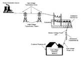
- Power distribution systemsinclude numerous sections, which transmit power at different voltages.
- the transition from one section to anothertypically is accomplished with a transformer.
- the sections of the power distribution system that are connected to the customers premisestypically are low voltage (LV) sections having a voltage between 100 volts (V) and 240V, depending on the system. In the United States, the LV section typically is about 120V.
- the sections of the power distribution system that provide the power to the LV sectionsare referred to as the medium voltage (MV) sections.
- the voltage of the MV sectionis in the range of 1,000V to 100,000V.
- the transition from the MV section to the LV section of the power distribution systemtypically is accomplished with a distribution transformer, which converts the higher voltage of the MV section to the lower voltage of the LV section.
- Power system transformersare one obstacle to using power distribution lines for data communication.
- Transformersact as a low-pass filter, passing the low frequency signals (e.g., the 50 or 60 Hz) power signals and impeding the high frequency signals (e.g., frequencies typically used for data communication).
- the low frequency signalse.g., the 50 or 60 Hz
- the high frequency signalse.g., frequencies typically used for data communication.
- power line communication systemsface the challenge of communicating the data signals around, or through, the distribution transformers.
- power linesare susceptible to ingress noise, which may vary from location to location.
- layout and network planning of a power line communications systemmay be difficult due to the unpredictability of the power line communications channels.
- a power line communications devicethat can service customers and also repeat the data for other network elements and that can be dynamically configured and re-configured by a network management system.
- the present inventionprovides a PLCS network element that provides communications to one or more user devices and may also repeat data for other network elements.
- the deviceincludes software for discovering its upstream gateway, for acting as a gateway for other devices, and for relaying dynamic host configuration protocol (DHCP) transmissions.
- DHCPdynamic host configuration protocol
- the deviceincludes software for receiving and processing commands from a remote computer system that may include commands enabling and disabling the repeater functionality.
- the devicealso may include software for receiving and processing configuration information that may include, for example, information of the other network devices for which it will repeat.
- FIG. 1is a diagram of an exemplary power distribution system with which the present invention may be employed
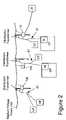
- FIG. 2is a diagram of a portion of an example power line communications system, with which an embodiment of the present invention may be used;
- FIG. 3is a schematic representation of a portion of an exemplary power distribution system in accordance with an embodiment of the present invention.
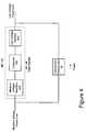
- FIG. 4is a block diagram of a bypass device, in accordance with an embodiment of the present invention.
- FIG. 5is a block diagram of a bypass device, in accordance with an embodiment of the present invention.
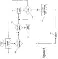
- FIG. 6is a flow chart of a portion of the software in an example embodiment according to the present invention.
- FIG. 7is a timeline of a portion of the communications for initializing a network element in an example embodiment of the present invention.
- FIG. 8is a timeline of a portion of the communications for initializing a network element device in an example embodiment of the present invention.
- FIG. 9is a timeline of a portion of the communications for enabling the repeater functionality in a network element device in an example embodiment of the present invention.
- FIG. 10is a timeline of a portion of the communications for changing a non-repeated network element device to be repeated in an example embodiment of the present invention.
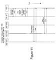
- FIG. 11is a timeline of a portion of the communications for changing a repeated network element to communicate with directly with a backhaul point in an example embodiment of the present invention
- power distribution systemstypically include components for power generation, power transmission, and power delivery.
- a transmission substationtypically is used to increase the voltage from the power generation source to high voltage (HV) levels for long distance transmission on HV transmission lines to a substation.
- HVhigh voltage
- Typical voltages found on HV transmission linesrange from 69 kilovolts (kV) to in excess of 800 kV.
- power distribution systemsinclude MV power lines and LV power lines.
- MVtypically ranges from about 1000 V to about 100 kV and LV typically ranges from about 100 V to about 240 V.
- Transformersare used to convert between the respective voltage portions, e.g., between the HV section and the MV section and between the MV section and the LV section. Transformers have a primary side for connection to a first voltage (e.g., the MV section) and a secondary side for outputting another (usually lower) voltage (e.g., the LV section).
- Such transformersare often referred to as distribution transformers or a step down transformers, because they “step down” the voltage to some lower voltage. Transformers, therefore, provide voltage conversion for the power distribution system.
- poweris carried from substation transformer to a distribution transformer over one or more MV power lines. Power is carried from the distribution transformer to the customer premises via one or more LV power lines.
- a distribution transformermay function to distribute one, two, three, or more phase voltages to the customer premises, depending upon the demands of the user. In the United States, for example, these local distribution transformers typically feed anywhere from one to ten homes, depending upon the concentration of the customer premises in a particular area. Distribution transformers may be pole-top transformers located on a utility pole, pad-mounted transformers located on the ground, or transformers located under ground level.
- the communication device of the present inventionmay form part of a PLCS to communicate signals to and from communication devices at the customer premises through the LV power line.
- the communications device of the present inventionmay facilitate the communication of data signals along the MV power line with 1) other power line communication devices such as bypass devices; 2) one or more backhaul points; 3) one or more power line servers; and/or 4) devices on a network such as the Internet.
- FIG. 2One example of portion of such a PLCS is shown in FIG. 2 and includes one or more bypass devices 100 , which may be formed by an embodiment of the present invention.
- the present inventionis embodied as a bypass device (BD) 100 to communicate data signals around the distribution transformer that would otherwise filter such data signals, preventing them from passing through the transformer or significantly degrading them.
- the BD 100is the gateway between the LV power line subnet (i.e., the devices that are communicatively coupled to the LV power lines) and the MV power line and communicates signals to and from user devices at the customer premises (CP) via the low voltage subnet 61 .
- the BD 100provides communication services for the user, which may include security management, routing of Internet Protocol (IP) packets, filtering data, access control, service level monitoring, signal processing and modulation/demodulation of signals transmitted over the power lines.
- IPInternet Protocol
- This example portion of a PLCSalso includes a backhaul point 10 , which may also be an alternate embodiment of the present invention.
- the backhaul point 10is an interface and gateway between a portion of a PLCS (e.g., an MV run) and a traditional non-power line telecommunications network.
- One or more backhaul points (BP) 10are communicatively coupled to an aggregation point (AP) 20 that in many embodiments may be at (e.g., co-located with), or connected to, the point of presence to the Internet.
- the BP 10may be connected to the AP 20 using any available mechanism, including fiber optic conductors, T-carrier, Synchronous Optical Network (SONET), or wireless techniques well known to those skilled in the art.
- the BP 10may include a transceiver suited for communicating through the communication medium.
- the AP 20may include a conventional Internet Protocol (IP) data packet router and may be directly connected to an Internet backbone thereby providing access to the Internet. Alternatively, the AP 20 may be connected to a core router (not shown), which provides access to the Internet, or other communication network. Depending on the configuration of the PLCS, a plurality of APs 20 may be connected to a single core router which provides Internet access.
- the core router(or AP 20 as the case may be) may route voice traffic to and from a voice service provider and route Internet traffic to and from an Internet service provider and/or video provider. The routing of packets to the appropriate provider may be determined by any suitable means such as by including information in the data packets to determine whether a packet is voice.
- the packetmay be routed to the voice service provider and, if not, the packet may be routed to the Internet service provider.
- the packetmay include information (which may be a portion of the address) to determine whether a packet is Internet data. If the packet is Internet data, the packet may be routed to the Internet service provider and, if not, the packet may be routed to the voice service provider. Additionally, if the packet includes voice, video or other time sensitive data, it may be accorded a higher priority to thereby reduce the latency thereof.
- a distribution point(not shown) between the BP 10 and the AP 20 .
- the distribution pointwhich include a router, may be coupled to a plurality of BPs 10 and provides routing functions between its BPs 10 and its AP 20 .
- a plurality of BPs 10are connected to each distribution point and each distribution point (of which there are a plurality) is coupled to the AP 20 , which provides access to the Internet.
- the PLCSalso may include a power line server (PLS) that is a computer system with memory for storing a database of information about the PLCS and includes a network element manager (NEM) that monitors and controls the PLCS.
- PLSallows network operations personnel to provision users and network equipment, manage customer data, and monitor system status, performance and usage.
- the PLSmay reside at a remote network operations center (NOC), and/or at a PLCS Point of Presence (POP), to oversee a group of communication devices via the Internet.
- NOCremote network operations center
- POPPoint of Presence
- the PLSmay provide an Internet identity to the network devices by assigning the devices (e.g., user devices, BDs 100 , (e.g., the LV modems and MV modems of BDs), BPs 10 , and AP 20 ) IP addresses and storing the IP addresses and other device identifying information (e.g., the device's location, address, serial number, etc.) in its memory.
- the PLSmay approve or deny user devices authorization requests, command status reports, statistics and measurements from the BDs, and BPs, and provide application software upgrades to the communication devices (e.g., BDs, BPs, and other devices).
- the PLSby collecting electric power distribution information and interfacing with utilities' back-end computer systems may provide enhanced power distribution services such as automated meter reading, outage detection, restoration detection, load balancing, distribution automation, Volt/Volt-Amp Reactance (Volt/VAr) management, and other similar functions.
- the PLSalso may be connected to one or more APs and/or core routers directly or through the Internet and therefore can communicate with any of the BDs, user devices, and BPs through the respective AP and/or core router.
- the PLCSmay further include indoor low voltage repeaters and outdoor low voltage repeaters.
- Indoor low voltage repeatersmay be plugged into a wall socket inside the customer premises.
- Outdoor low voltage repeatersmay be coupled to the external low voltage power line conductors extending from the transformer and therefore, be located between the customer premises and the BD 100 . Both the indoor low voltage repeaters and outdoor low voltage repeaters repeat data on the low voltage power line to extend the communication range of the BD 100 and power line modem.
- data floworiginates from a user device, which provides the data to a power line modem (PLM) 50 , which is well-known in the art.
- PLMpower line modem
- Various electrical circuits within the customer's premisesdistribute LV power and data signals within the customer premises.
- the customerdraws power on demand by plugging a device into a power outlet.
- the customermay plug the PLM 50 into a power outlet to digitally connect user devices to communicate data signals carried by the LV wiring.
- the PLM 50thus serves as an interface for user devices to access the PLCS.
- the PLM 50can have a variety of interfaces for customer data appliances.
- a PLM 50can include a RJ-11 Plain Old Telephone Service (POTS) connector, an RS-232 connector, a USB connector, a Ethernet 10 Base-T connector, RJ-45 connector, and the like.
- POTSPlain Old Telephone Service
- RS-232 connectorRS-232 connector
- USB connectorRS-232 connector
- Ethernet 10 Base-T connectora Ethernet 10 Base-T connector
- RJ-45 connectorEthernet 10 Base-T connector
- the user device connected to the PLM 50may be any device capable of supplying data for transmission (or for receiving such data) including, but not limited to a computer, a telephone, a telephone answering machine, a fax, a digital cable box (e.g., for processing digital audio and video, which may then be supplied to a conventional television and for transmitting requests for video programming), a video game, a stereo, a videophone, a television (which may be a digital television), a video recording device (which may be a digital video recorder), a home network device, a utility meter, or other device.
- the PLM 50transmits the data received from the user device through the LV power lines to a BD 100 and provides data received from the LV power line to the user device.
- the PLM 50may also be integrated with the user device, which may be a computer.
- the functions of the PLMmay be integrated into a smart utility meter such as a gas meter, electric meter, water meter, or other utility meter to thereby provide automated meter reading (AMR).
- AMRautomated meter reading
- the BD 100typically transmits the data to (and receives the data from) the backhaul point 10 , which, in turn, transmits the data to (and receives the data from) the AP 20 .
- the AP 20then transmits the data to (and receives the data from) the appropriate destination (perhaps via a core router), which may be a network destination (such as an Internet address) in which case the packets are transmitted to, and pass through, numerous routers (herein routers are meant to include both network routers and switches) in order to arrive at the desired destination.
- FIG. 3provides a schematic representation of a segment of the medium voltage power line of an example portion of a PLCS.
- this exampleincludes one BP 10 and six BDs 100 a–f .
- the BP 10may be communicatively coupled to another set of bypass devices (e.g., on the other side of the BP 10 ).
- the BDs 100 a–fmay or may not be on the same power line conductor as the BP 10 (because the data signals may cross couple between MV conductors). Communications in this example are point-to-multipoint in that the BP 10 transmits communications signals on the MV power line, which may be received by all of the BDs 100 .
- the communicationsmay include addressed data packets (e.g., internet protocol (IP) data packets). Consequently, while all of the BDs 100 may receive the data packets, only the BD 100 having an address corresponding to the address in the packet processes the packet. Typically, the other BDs 100 will ignore packets not containing their address information. In this example, transmissions from the BDs 100 will include address information of the BP 10 , which typically will receive and process the transmissions. While the BDs 100 may receive the transmissions from the other BDs 100 , normally they will ignore those transmissions because the packets will not have the address information of the receiving BD 100 (but instead have the address of the BP 10 ).
- IPinternet protocol
- the PLCSmay have a maximum communications distance (MCD) (along the MV power line) over which a BP 10 and a BD 100 may communicate reliably.
- MCDmaximum communications distance
- this distancemay vary from location to location (e.g., from street to street), which makes planning the PLCS network difficult.
- a communication link between a BD 100 and its BP 10is unreliable, one option is to install a second BP 10 closer to the BD 100 to service the BD 100 .
- installation of BPscan be costly due to costs of installation time, equipment, and the necessity of providing a backhaul link, which may require installing a fiber optic cable or wireless backhaul link.
- the communications link between a BD 100 and its BP 10may be reliable at times and unreliable at other times and/or may become unreliable sometime after installation of the network.
- one solutionis to install a new BP 10 closer to the BD 100 for communications, to service the BD 100 .
- this solutionis costly.
- Another solution to the problemis to install a dedicated repeater between the BP 10 and the BD 100 .
- thisrequires sending personnel to perform the installation of the repeater (i.e., a truck roll), which can be costly and can take days or weeks to complete during which time the subscriber of the PLCS service may be without reliable service or without any service.
- the present inventionmay reduce the need to install additional BPs, backhaul links, and dedicated repeater devices by extending the reach of existing BPs beyond the MCD through the use of existing network elements.
- the MCD of BP 10 in FIG. 3is such that it can communicate with BDs 100 a–d , but can not directly reliably communicate with BD 10 e or BD 10 f .
- the MCD of BDs 100 b–dare similarly shown. However, BDs 100 b–d are located such that any of BDs 100 b–d can directly reliably communicate with BP 10 and both BDs 100 e and BD 100 f .
- One example embodiment of the present inventionprovides for a BD 100 , (such as BD 100 b–d ), to repeat communications for BDs 100 e and 100 f , which cannot directly communicate with the BP 10 .
- the BP 10cannot communicate with other BDs 100 after installation.
- the repeater functionality of one example embodiment of the present inventionalso may be enabled remotely without the need to send personnel (or equipment) to the site.
- This example embodiment of the present inventionincludes a BD that also can be configured to repeat communications.
- the repeating functionality of the deviceallows the MCD or communications range of a BP 10 to be expanded such that communications devices (e.g., BDs 100 ) with unsatisfactory connectivity (e.g., due to noise or attenuation of signals) can be improved by repeating to make their connections satisfactory.
- the repeater functionalitytypically will extend the ‘reach’ of the BP 10 to include communications devices at distances that normally could not be reached by direct transmission between the device and the BP 10 .
- the repeating BD 100reduces the number of BPs 10 needed to be deployed to cover the geographical area of a PLCS, it also reduces the amount of backhaul media (e.g., fiber optic cable or wireless links) that needs to be deployed, thereby providing a significant economic improvement to the PLCS.
- backhaul mediae.g., fiber optic cable or wireless links
- a single devicemay repeat communications for other devices coupled to the MV power line and also provide communications to one or more user devices (such as those connected to the LV subnet or that are linked to the device via a wireless link).
- a BD 100 in which the repeater functionality has been, or is being enabledgenerally will be referred to herein as a repeating BD 100 (“RBD 100 ”).
- the repeating BD 100typically will receive downstream packets addressed to it from a BP 10 and retransmit them on the MV power line for reception by another BD 100 .
- the RBD 100may receive packets addressed to it that are transmitted from one or more BDs 100 and retransmit those packets on the MV power line for reception by the BP 10 .
- the RBD 100includes sufficient information stored in its memory (e.g., bridge table or routing table) to receive packets addressed to it, and to re-address those packets with the address of the corresponding destination device (e.g., BP 10 or BD 100 ).
- the demodulation of received packets, and modulation and retransmission of packetsimproves the signal to noise ratio (SNR) of the data traversing the power line.
- the repeater functionality of the BD 100may extend the communications reach in such a way as to allow devices coupled to the MV power line that cannot communicate with BP 10 , to be able to communicate with that BP and operate as a child device of that BP 10 .
- the repeater functionalitymay reside in any or all BDs 100 , with configuration and activation being remotely enabled and disabled from the PLS automatically or in response to an input from an operator.
- more than one BD 100may be enabled as repeating BDs 100 on a MV run so that data communicated between a BP 10 and a BD 100 may be repeated two or more times.
- one RBD 100 on an MV runmay repeat for some BDs 100 and another RBD 100 may repeat for other BDs 100 on that same run.
- the flexibility of the functionalitymay allow the PLS operator (at the network operations center or NOC) to decide where and when to use a repeater without requiring pre-planning or additional hardware deployment and to adapt to changing conditions.
- the PLS softwaremay include code segments for transmitting commands to 1) enable the repeater functionality of a BD 100 , 2) disable repeater functionality of a BD 100 , 3) configure a BP 10 to communicate to specific BDs 100 through a specific RBD 100 , 4) configure a RBD 100 to repeat for specific BDs 100 , and 5) configure specific BDs 100 to route traffic through a specific RBD 100 .
- the PLSalso may store the hierarchical configuration of the BP 10 , RBDs 100 , BDs 100 for each MV run in the network in its memory (or database) to help facilitate and maintain the desired route configuration.
- This hierarchy informationmay include address and other information showing the following for each BP 10 : 1) the BDs 100 directly communicating with the BP 10 , 2) the BDs 100 directly communicating with the BP 10 and also acting as RBDs 100 , 3) the BDs 100 communicating through a RBD 100 and also acting as RBDs 100 , and 4) the BDs 100 that are communicating through an RBD 100 (and are not acting as an RBD 100 ).
- each BD 100may include the repeater functionality, which may be enabled or disabled as desired by the operator.
- the repeater functionalitymay be combined with the functionality of other communications devices.
- the repeating communications devicemay include a medium voltage port (for communications over the MV power line) and a wireless transceiver for communications to the user devices at the customer premises (e.g., instead of an LV port).
- a bypass devicemay bypass the transformer without coupling to the LV power line at the transformer.
- the repeater functionalitymay be combined with the backhaul functionality.
- a BPmay repeat backhaul communications, such as those from other BPs 10 (or other MV runs) or its BDs 100 , over the MV power line using a transmission scheme orthogonal to those between the repeating BP 10 and its child devices (BDs 100 ).
- a transmission schememay include one or more of surface wave transmissions, ultra wideband (UWB) transmissions, a different (orthogonal) frequency band, or communicating over the neutral conductor (instead of or in addition to the MV power line conductor).
- UWBultra wideband
- such a BP 10may simultaneously communicate (receive or transmit) a conductive signal over the MV power line (e.g., an OFDM signal to or from a BD 100 or RBD 100 ) and a UWB signal or surface wave signal (e.g., for backhaul communications to or from a RBD 100 or BP 10 ).
- a conductive signalover the MV power line (e.g., an OFDM signal to or from a BD 100 or RBD 100 ) and a UWB signal or surface wave signal (e.g., for backhaul communications to or from a RBD 100 or BP 10 ).
- a BP 10therefore, may not need to have a separate backhaul link connection.
- the non-power line backhaul linkmay be connected to the upstream BP 10 or other device receiving the repeated data.
- RBDs 100 and BPs 10may include a first MV interface for communications via OFDM (e.g., for communications between devices of the same MV run) and a second MV interface for UWB communications, surface wave communications, or communications in a second frequency band (e.g., for communications being repeated from (or to) other BPs 10 of other MV runs).
- the first and second MV interfacemay share some components such as, for example, the MV coupler.
- the MVmay be used to provide two or more simultaneously available communications channels.
- the embodiment described belowincludes a BD 100 that operates as BD 100 for bypassing a pole-mounted transformer.
- the present inventionmay be equally applicable for use in bypassing other types of transformers (such as pad mount or underground).
- the BD 100may provide a path for data to bypass the transformer by being coupled to the same MV power line conductor to which the transformer is coupled or to a different MV power line conductor and, in either instance, may be coupled to the same LV power lines to which the bypassed transformer is coupled.
- the BDs 100may or may not be physically coupled to the same power line conductor to which the BP 10 is physically connected. For example, in overhead PLCS, high frequency data signals may cross-couple between the power line conductors.
- the BD 100 described hereinprovides bi-directional communications and includes the functional block diagrams shown in FIG. 4 .
- this embodiment of the BD 100includes a MV power line interface (MVI) 200 , a controller 300 , and a LV power line interface (LVI) 400 .
- Both the MVI and LVImay include an adaptive and/or dynamic transmitter to transmit signals at various power levels as determined by the controller 300 , which may change the output power in response to a command from the PLS or automatically due to changes in line impedance.
- the BD 100is controlled by a programmable processor and associated peripheral circuitry, which form part of the controller 300 .
- the controller 300includes memory that stores, among other things, routing information and program code, which controls the operation of the processor.
- the LVI 400may include a LV power line coupler 410 , a LV signal conditioner 420 , and a LV modem 450 .
- the router 310forms part of the controller 300 and performs routing functions. Router 310 may perform routing functions using layer 3 data (e.g., IP addresses), layer 2 data (e.g., MAC addresses), or a combination of layer 2 and layer 3 data (e.g., a combination of MAC and IP addresses).
- the MVI 200may include a MV modem 280 , a MV signal conditioner 260 , and a power line coupler 210 .
- the controller 300may perform other functions including controlling the operation of the LVI 400 and MVI 200 functional components and responding to PLS commands and requests. A more complete description of the hardware, firmware, of the BD 100 and its functionality is described below.
- This embodiment of the BD 100provides bi-directional communications around the distribution transformer to thereby provide a first communications path from the LV power line to the MV power line and a second path from the MV power line to the LV power line.
- BD 100can receive and transmit data to one or more user devices in one or more customer premises via the LVI 400 , which may be connected to a plurality customer premises via a plurality of LV power lines.
- the BD 100may receive and transmit data with other network elements, such as one or more the BPs 10 and other BDs 100 , via the MVI 300 .
- the BD 100While skilled in working with power lines, personnel installing the BDs 100 , who typically are utility linemen, often have little or no experience in working with communications networks. Consequently, it is desirable to have a system that permits easy installation of the BDs 100 without the need to perform network configuration or other network installation procedures.
- the BD 100Upon being physically installed and powered up, the BD 100 typically will not immediately be part of the PLCS network in that, among other things, it does not have an IP address assigned to it, the address of an upstream gateway, user device information, and has not been activated.
- “Auto-Provisioning”is the term used to refer to the procedure performed to get a new network element (e.g., a BD 100 , or BP 10 ) onto the PLCS network by providing such information and activation.
- each network elementincludes a unique identifier, which may be a serial number.
- the enclosure of the BD 100has a barcode that the installer may scan to record the serial number.
- the installeralso may record the location (e.g., transformer or pole number) of the installed device. This information (the identifying information and location) is provided to a network administrator for input into the PLS for storage. Alternately, the installer may wirelessly transmit the information to the PLS for reception and storage by the PLS.
- the BD 100may implement the Gateway Negotiation Protocol (GNP), which provides a method for the BD 100 (which may not yet have an IP address) to discover gateways on the MV power line (e.g., the address to be used for upstream communications).
- GNPGateway Negotiation Protocol
- the GNPis a layer two protocol, but other embodiments may additionally, or instead, use other layers (e.g., layer three).
- the GNPsets a pathway for initiating dynamic host configuration protocol (DHCP) negotiation with its BP 10 and to eventually get its Activation from the PLS.
- This pathwayincludes an upstream gateway to which the BD 100 “attaches”, meaning that the BD 100 typically will use the gateway for future upstream communications unless it is specifically instructed otherwise or reboots and acquires a different gateway address via GNP.
- DHCPdynamic host configuration protocol
- the GNPprovides gateway information that may include information of the address of the device to be used by the BD 100 for communicating with its DHCP server, which in this embodiment may be the address of its BP 10 or the address of a repeating BD (RBD) 100 .
- the GNPmay provide the information of the address of the DHCP server itself, which typically will be the address of a BP 10 in this embodiment.
- GNPprovides a method to discover the IP address (layer 3) of the Gateway device along with a MAC address (layer 2) of the upstream device (e.g., an RBD 100 or BP 10 ).
- the GNPincludes four types of messages: Solicit, Advertise, Attach, Acknowledged/Not-Acknowledged (ACK/NACK).
- BDs 100may transmit Solicit and Attach messages.
- Gateway devicessuch as RBDs 100 and BPs 10 may transmit Advertise and ACK/NACK messages.
- a BD 100may broadcast a Solicit message (step 121 in FIG. 6 ), which indicates that the BD 100 is searching for a gateway device for DHCP negotiations and/or for communications.
- those gateway devices(RBDs 100 and BPs 10 ) that receive and decrypt the Solicit message may respond by transmitting an Advertise message, which indicates their availability as a gateway.
- the Advertise messagemay include a Link Figure of Merit (LFoM) (which may be based on bytes 40 information) and a gateway flag.
- the PLSmay assign a BD 100 an upstream gateway.
- LEOMLink Figure of Merit
- the gateway flagWhen the gateway flag is set in the Advertise message, it indicates that the responding device (the device transmitting the Advertise message) has been designated the gateway device (e.g., by the PLS) for the BD 100 transmitting the Solicit message.
- the LFoM information in the Advertise messageincludes data relating to the quality of the communications link between the devices and may include bit error rate (BER) information or information derived from the BER. As shown in FIG. 6 , the response is received and processed by the BD 100 .
- BERbit error rate
- the BD 100may transmit an Attach message at step 125 , subsequently receive an ACK at step 126 , and then update its configuration information at step 127 , and proceed to DHCP at step 128 .
- the initializing BD 100may transmit multiple Solicit messages before attaching to a responding gateway (e.g., a RBD 100 or BP 10 ).
- the multiple Solicit messagestypically will increase the chances that the BD 100 will discover its most reliable temporary gateway.
- the multiple GNP Solicit messagesmay allow the BD 100 to collect multiple LFoM samples from each responding potential gateway device. The BD 100 may average the LFoM data from the responding gateway devices to determine the most reliable temporary gateway.
- a device that has been designated as the assigned gateway(e.g., by the PLS) will include an assigned gateway flag in its Advertise message (in response to the Solicit message). If an assigned gateway responds to the Solicit message, a BD 100 typically will attach to it, regardless of the NE Type and LFoM of other responding gateways. In the event that two or more gateways indicate that they are the assigned Gateway, the BD 100 may attach to the first gateway responding with the assigned Gateway flag set—or, in an alternate embodiment, to the gateway device with best LFoM data.
- a BD 100may select the gateway by scoring each gateway responding to its Solicit message. This score may be related to the quality of the link between the BD 100 and the responding gateway device and, as an example, may be related to the average LFoM data.
- the LFoM threshold valuemay include a minimum LFoM value for BPs 10 and a separate minimum LFoM value for RBDs 100 , both of which may be transmitted from the PLS (and stored in memory) or pre-configured in memory of the BD 100 .
- the operatormay provide an input to the PLS to cause the software of the PLS to transmit the BP 10 LFoM and BD 100 LFoM thresholds for one or more BDs for use in GNP gateway device selection.
- the BD 100may include a software segment for receiving and processing LFoM threshold information transmitted from the PLS.
- the BD 100may have default minimum threshold values for the BP 10 and RBD LFoM used in BD 100 gateway selections during GNP negotiations stored in memory.
- the controller of the BD 100may implement an algorithm for weighted selection of its gateway during GNP negotiations.
- Advertise messages with a LFoM value from a BP 10 that meet or exceed the BP LFoM thresholdare selected above a RBD 100 , whether or not the with LFoM information from that RBD 100 meets or exceeds the RBD 100 LFoM threshold or that of the assigned BP 10 .
- Advertise messages with a LFoM value from an RBD 100 that meets or exceeds the RBD 100 LFoM thresholdmay be selected above a BP 10 whose LFoM value does not meet or exceed the BP 10 LFoM threshold.
- the selection between devices of the same NE typesis given to the device with the higher LFoM value. For example, if the choice is between two BPs 10 , the BP 10 with the higher LFoM value typically will be selected. Similarly, if there were no BP 10 Advertise messages with LFoM data above the BP LFoM threshold and the choice is between RBDs 100 , the RBD 100 with the higher LFoM value typically will be selected (provided at least one had a LFoM value above the RBD 100 LFoM threshold).
- the BD 100determines its upstream gateway, it transmits an Attach message to that gateway device at step 125 .
- the gateway deviceIn response to receiving the Attach message, the gateway device typically will respond with an Acknowledge message, which is received by the BD 100 at step 126 .
- a BD 100Upon receiving the GNP ACK at step 126 , a BD 100 typically will also configure its DHCP client with the Gateway IP Address at step 127 .
- the Gateway IPmay be a layer 3 address used to route all traffic being sent to an upstream network.
- the next upstream hop MAC addressmay be a layer 2 address used to reach that Gateway IP address.
- Static ARPmay be used to set this binding so that the BD 100 knows how to communicate with a foreign subnet correctly. Consequently, the BD 100 may make the following ARP entries (store in memory) upon receiving an Acknowledge message from its gateway device:
- the DHCP client of the BD 100will use this address as the address for communications with its DHCP server at step 128 .
- a BD 100may then attempt DHCP request at step 128 . In this situation, DHCP messages will be broadcast. The BD 100 may reattempt GNP negotiations if the DHCP attempt fails.
- Each GNP messagetypically will include much of the following information:
- the followingis an example of the information received via an example GNP by an initializing BD 100 , a RBD 100 , and a BP 10 .
- the relationship between these example devicesis as follows:
- BP 10In order to communicate with BD 100 (either IP address 10.1.1.3 or subnet 10.2.2.x) BP 10 must have data indicating that it must communicate through RBD 100 's NB interface. Consequently, BP 10 may receive configuration data that specifies the RBD 100 's NB MAC address (MV modem MAC address) in a static ARP that binds 10.1.1.3 and 10.2.2.x subnet to the RBD 100 NB MAC address.
- RBD 100 's NB MAC addressMV modem MAC address
- RBD 100needs to know that it repeats for 10.1.1.3 and foreign LV subnet 10.2.2.x.
- RBD 100 's configuration dataspecifies static ARP that binds 10.1.1.3 and 10.2.2.x to BD 100 's NB interface MAC address.
- BD 100needs to know that its DHCP server is as 10.1.1.1 and its Gateway IP address is 10.1.1.2, but its DHCP Server and gateway next hop MAC address is that of RBD 100 NB interface.
- the GNPresults in a static ARP entry binding 10.1.1.1 and 10.1.1.2 to the RBD 100 NB MAC address.
- the BD 100may communicate with its DHCP server (e.g., BP 10 ). Typically, the BD 100 will transmit a request, such as a DHCP request, to the BP 10 designated by the gateway information. If the BD's gateway is an RBD 100 , the BD 100 will communicate with its BP 10 via the RBD 100 . If the BD's gateway is a BP 10 , the BD 100 will communicate with the BP 10 directly.
- a DHCP servere.g., BP 10
- the BD 100will transmit a request, such as a DHCP request, to the BP 10 designated by the gateway information.
- the BD's gatewayis an RBD 100
- the BD 100will communicate with its BP 10 via the RBD 100 .
- the BD's gatewayis a BP 10
- the BD 100will communicate with the BP 10 directly.
- the BP 10may assign the requested information to the MV interface (e.g., assigns an IP address to be associated with the MV modem 280 of the BD 100 ), and the MV subnet mask and transmits the information to the BD 100 .
- the BP 10may transmit the IP address of the BP 10 to be used as the BD's network gateway address (if necessary), and the IP address for the PLS.
- the BD 100receives the information from the BP 10 and stores it in its non-volatile memory.
- the BD 100After receiving and storing the DHCP information, the BD 100 then transmits an Alive Alert to the PLS (using the IP address received during the DHCP negotiation via the gateway negotiated during GNP) indicating that the BD 100 is operating and connected to the network.
- the Alive Alertmay include information identifying the BD 100 , configurations of the BD 100 (e.g., MAC addresses of the LV modem 450 and MV modem 280 ), the IP address of the MV Interface (i.e., the IP address assigned to the MV modem 280 received from the BP 10 ), MV subnet mask for use by the BD MV interface (much of which was received from the BP 10 ), and the Gateway IP address.
- This informationis stored by the PLS in the network elements database.
- the PLSmay activate the BD 100 by transmitting an activation command and assigning and transmitting to the BD 100 a LV subnet mask and a LV Interface IP address (i.e., the IP address used to communicate with the LV modem 450 ).
- the gateway IP address of the BD 100(as determined by the GNP) can be modified by the PLS to set the assigned gateway of the BD 100 to a different gateway device (and associated addresses). If this is done, the newly assigned gateway device is informed of the selection so that subsequent GNP negotiations with that BD 100 will include responses with the gateway flag set.
- the PLSmay transmit customer information to the BD 100 , which may include such information as data filtering information, keys (e.g., network encryption keys) for the user devices, user device IP addresses, and subscription levels for the various users and/or user devices.
- the PLSmay configure the BD 100 by transmitting DNS addresses (e.g., a first and second DNS address), and a registration server IP address or URL. This information is stored by the PLS (in the network elements database) and the BD 100 .
- the BD 100may be programmed to allow the user device to access only the domain name servers and registration server.
- the BD 100may transmit an activation acknowledgement to the PLS, indicating that it is Online and can communicate user data.
- the activation acknowledgmentmay be stored in the PLS database indicating that the BD 100 is Online.
- the RBD 100may act as a relay for all DHCP messaging between the repeated BD 100 and the DHCP Server.
- this DHCP relay functionalitymay be performed only for devices that have fully negotiated the RBD 100 as their gateway during GNP negotiations.
- the initializing BD 100 c devicemay perform the GNP negotiation to obtain information of the IP address of the DHCP Server (i.e., the IP address of the BP 10 ) for the MV link.
- RBD 100 bis selected as the gateway device.
- the devicemay establish a static ARP mapping the BP's IP address to the MAC address of the device's gateway (RBD 110 b ).
- the device's DHCP clientmay send unicast messages (i.e., addressed messages) to the DHCP relay agent on the MV link.
- the RBD 100 bwill inspect these messages and determine that the source of the message is a device for which it is repeating, will add the appropriate DHCP relay information, and retransmit the modified unicast message back onto the MV link.
- the BP's DHCP Servermay receive the modified DHCP unicast message, process it and transmit DHCP responses as unicast messages by way of the gateway address of the RBD 100 b in the DHCP message.
- the RBD 100 bwill inspect the DHCP response unicast messages and retransmit the modified DHCP response as a unicast message to the BD 100 c on the MV link.
- BD 100 cwill receive the DHCP response and will process the response message accordingly.
- the unreliable nature of the MV link connectionscauses problems due to messages not being received by the intended target.
- the unreliable naturepotentially has the opposite affect in that messages could arrive from both the originator (BP 10 ) and the RBD 100 .
- unicast messagese.g., addressed messages
- the initializing device (BD 100 c ) and the RBD 100using the MAC address of the RBD 100 b as the hop, the issue of multiple retransmitted messages is avoided and the RBD 100 b accounts for the unreliable transmission.
- the BD 100may store and set static routes (IP addresses of the devices) and Address Resolution Protocol (ARP) information.
- ARPAddress Resolution Protocol
- ICMPInternet Control Message Protocol
- the RBD 100might send a redirect message back to the transmitting device indicating it should go directly to the BP 10 and redirection would be done each time regardless as to whether or not the device could see the BP 10 directly (i.e., communicate with the BP 10 without the data being repeated by the RBD 100 ).
- ICMP redirectwere not disabled in a RBD 100
- the RBD 100might send a redirect message back to the transmitting device indicating it should go directly to the BP 10 and redirection would be done each time regardless as to whether or not the device could see the BP 10 directly (i.e., communicate with the BP 10 without the data being repeated by the RBD 100 ).
- such an occurrenceis not desirable and contradicts the point of enabling the RBD 100 to repeat communications between the BP 10 and the BD 100 .
- the RBD 100also repeats pings to, from and through the BD 100 with respect to the BD's LV modem, MV modem, and foreign subnets, including to/from customer devices, the BP 10 , or test machines within the PLCS network.
- the RBD 100also may repeat TTCP traffic to, from, and through the BD 100 with respect to the BD 100 LV, MV and foreign subnets, including to/from customer devices, the BP 10 , and/or test devices within the PLCS network.
- a BD 100 that is acting solely as a bypass deviceit may be desirable to enable the repeater functionality in two or more BDs to further extend communications of the BP 10 .
- this example embodiment of the PLCS and BDs 100includes the ability to enable or disable the repeating functionality within any BD 100 from the PLS operator console.
- the enablement and disablement of the repeater functionality in the BDs 100 , and the configuration of the other network elementsmay be performed by the PLS in response to user inputs from the NOC operator, NOC interfaces and/or automatically.
- the PLSmay change a BD 100 currently repeated by one RBD 100 to be repeated by a different RBD 100 .
- Part of enabling repeater functionality within a BD 100may include the configuration of other BDs 100 for which it will repeat.
- the PLSallows the NOC operator to select which BD 100 on an MV run to enable repeater functionality.
- the PLSmay also provide an option to the NOC operator to identify the devices for which the RBD 100 should repeat, out of the list of alive or activated devices on that MV run. Alternately, this may be performed automatically by the PLS via software code segment executed on the PLS. This identification may be based on the quality of the existing communication links for those devices, which may be based on LFoM information transmitted to the PLS.
- This configurationmay be optional at the time the repeater function is enabled because the devices for which the RBD 100 is to repeat may not be known (or installed) at the time of enablement.
- the PLSmay determine and transmit both IP and MAC address information needed by the RBD 100 to ensure the proper repeating of both traffic from the repeated devices to/from a subnet foreign to the MV link and traffic between the repeated devices MV interface to/from the BP 10 and foreign subnets beyond the BP 10 .
- the PLSmay also transmit to the BP 10 information identifying a RBD 100 as repeating for other of the BP's devices.
- the repeated device configurationprovides information identifying the next hop for traffic coming from a foreign subnet down to either the repeated BDs 100 MV interfaces or the repeated BDs 100 LV subnets.
- the BP 10also uses this information to determine what the next hop is for traffic directed from the BP 10 to the repeated devices (e.g., what RBD 100 is the gateway for the BD 100 ).
- the BD 100receives and stores the configuration information (e.g., transmitted from the PLS) in memory, which may include, but is not limited to, the repeater function Enable/Disable Status; the repeated BD MV interface ARP information (e.g., address information for the MV modems of the repeated BDs 100 ); and the repeated BD southbound (i.e., downstream) interface Route information.
- the route informationmay include the subnet routes and the BD 100 NB MAC address for ARP binding in the RBD 100 .
- a BD 100once a BD 100 has been configured to communicate via a RBD 100 , it will always use that RBD 100 for communications to the BP 10 while this configuration is in effect and the device has not rebooted.
- FIG. 9depicts an example of some of the communications employed to enable the repeater functionality.
- BD 100 bis being enabled as a repeater sometime after activation.
- BD 100 bis enabled as a repeater and provided with new configuration information.
- BD 100 bmay then respond as a potential gateway device to other BDs 100 , such as BDs 100 c–d , (as well as 100 a and 100 e , although they may not choose to select 100 b as their gateway) that initialize thereafter and transmit Solicit messages.
- FIG. 10depicts an example of some of the communications employed to enable the repeater functionality.
- BD 100 bis being enabled as a repeater for BD 100 c .
- BD 100 cis deactivated by the PLS at the BP 10 and at BD 100 c until new routing information is transmitted to all involved devices.
- BD 100 bis enabled as a repeater and provided with new configuration information and new gateway information is provided to BD 100 c .
- BD 100 cis sent an activation from the PLS to once again enable routing between its MV and LV interfaces.
- FIG. 11depicts an example of some of the communications employed to reconfigure a device so as to no longer repeat for another BD.
- RBD 100 bis repeating for BD 100 c and it is desirable to configure BD 100 c to communicate directly with BP 10 .
- BD 100 bis being reconfigured so as not to repeat for BD 100 c .
- BD 100 c and RBD 100 bare deactivated by the PLS at the BP 10 until new routing information is transmitted to all involved devices (e.g., BD 100 c , RBD 110 b , BP 10 ).
- BP 10 and RBD 100 bare provided with new configuration information and new gateway information is provided to BD 100 c .
- BD 100 cmay be sent an activation from the PLS to enable routing between its MV and LV interfaces and BD 100 c will communicate directly with BP 10 , instead of through RBD 110 b .
- RBD 100 bmay be sent an activation from the PLS (although it may no longer be a repeating BD 100 ).
- the MV power linemay be segmented into different PLCS sections by the network designer.
- Each PLCS sectionmay be served by a different BP 10 .
- the BP 10may be deployed near the center of the PLCS section and communicate with BDs 100 on each side of the BP 10 .
- Each PLCS sectionmay communicate using a different network encryption key (NEK) (or set of keys) to thereby prevent devices of different PLCS sections from receiving and processing data transmitted from each other.
- NEKnetwork encryption key
- the MV power lineis a somewhat unpredictable communications channel. Consequently, it may be desirable to have a BD 100 that is communicating (or was intended to communicate) with a first BP 10 to instead communicate with a second BP 10 . However, in order to do so, the BD 100 must be provided with the NEK for the other PLCS section and BP 10 .
- the BD softwaremay include an algorithm for receiving and processing a command transmitted from the PLS to change the BD's MV NEK, thus causing the BD 100 to update its memory, non-volatile memory, and MV power line interface to match the specified NEK (i.e., change the NEK used by the MV modem).
- the methodmay include the option of clearing the BD's configuration, not including the new NEK, and, if the clear configuration option is selected, forcing a reboot such that the BD 100 restarts using the new MV NEK and defaults to the Alive state. The reboot may then cause the BD 100 to obtain its upstream gateway from the devices on the new PLCS section.
- the BD 100may include a software segment for receiving and processing commands from the PLS for specifying MAC addresses to which the BD 100 should not serve GNP Advertise messages (e.g., when the RBD 100 is acting as a potential gateway device).
- the PLSis responsible for constructing and maintaining the RBD 100 to BD 100 hierarchy for each BD 100 on the MV link.
- the PLSmay use the Northbound Interface Gateway Address received in the Alive Alert to construct the hierarchy.
- the Alive Alert's Northbound Interface Gateway Addressmay contain the IP address of the BD's BP 10 .
- the Alive Alert's Northbound Interface Gateway Addressmay contain the IP address of the RBD 100 if the BD 100 attached to an RBD 100 .
- the PLSwill associate the BD 100 to a chain of hops describing how packets will traverse to/from the BD 100 on the MV link. Portions of this hop information, which may be stored in memory, must be provided to the BD's BP 10 and each RBD 100 repeating for the BD 100 . Thus, the PLS may transmit the information to those BDs 100 and BP 10 , all of which include software for receiving and storing the information. These RBDs 100 and BP 10 typically will use this information to construct the appropriate ARP and route entries for repeated BDs 100 .
- the PLSmay include software for allowing the operator to reconfigure the path of a BD 100 in such a manner as to allow for any of the following: (1) changing a BD 100 from a direct BP 10 connection to being repeated by one or more RBDs 100 (see FIG. 10 ); (2) changing a repeated BD 100 to directly communicate with the parent BP 10 (see FIG. 11 ); (3) changing an RBD 100 to be repeated by another RBD 100 ; (4) changing a repeated RED 100 to directly communicate with the parent BP 10 .
- the PLSmay include software functionality for providing a method by which an operator may select a BD 100 to become an RBD 100 . Furthermore, upon selection, the PLS may transmit new configuration information indicating that it should enable repeater functionality and the BD 100 will update its configuration in memory accordingly.
- the PLSmay include software configured to support the selection of devices to be repeated by a RBD 100 . Furthermore, the PLS software may cause the transmission of the repeated BD 100 configuration information to the parent BP 10 , the RBD 100 , any intermediate RBDs 100 , and the repeated BDs 100 . As discussed, the PLS may store the data path for repeated BDs 100 and their LV subnets, including the hierarchy of RBDs 100 and the parent BP 10 .
- the PLSmay include software for transmitting a request for the BD's configuration information, which includes the gateway negotiated via the GNP.
- the BDs 100may include software for receiving the request and transmitting the information.
- the PLSalso may include software to compare the received information with the information stored in the PLS database memory device and to provide an electronic, visual and/or audible operator alert should the received gateway information be different from what is stored in the PLS database.
- the PLSmay include software for allowing an operator to replace a BD 100 with another physical BD 100 unit that will receive and store the same configuration as the BD 100 being replaced. Furthermore, the PLS may notify the parent BP 10 , and any repeated BDs 100 served by the replaced RBD 100 , of the new data path through the replacement RBD 100 . In this scenario, the MAC addresses of the replaced unit may change while the other information (such as IP addresses), which may be transmitted from the BP 10 and/or PLS may remain the same (i.e., provided to the new unit).
- the PLSmay include software functionality to verify that the configuration of the MV power line run is such that no BDs 100 are being repeated by an RBD 100 that is scheduled to be removed. Should the MV run be configured with BDs 100 still being repeated by the RBD 100 to be removed, the PLS may cancel the operation and notify the operator of the situation via an alert. To make this determination, the PLS may search its database to determine if the RBD 100 to be removed forms part of the data path (i.e., is a gateway) for any of the other BDs 100 or to determine whether the BD 100 to be removed has had its repeater function enabled (if not it is not repeating for any BDs).
- the PLSmay include software for pre-provisioning an as yet unactivated BD 100 to be a RBD 100 . Furthermore, the PLS may include software for allowing an operator to pre-provision which BDs 100 will be repeated by the pre-provisioned RBD 100 . This software of the PLS may, upon activation of a pre-provisioned RBD 100 , transmit a notification to the parent BP 10 and any BDs 100 selected to be repeated by the RBD 100 , of the data path through the pre-provisioned RBD 100 .
- the PLSmay include software for processing BD 100 statistics, (which includes RBD statistics).
- the PLSmay include software for receiving and processing BD 100 statistics ready alert transmitted from a BD 100 (including RBDs).
- the PLSmay include software for the automatically logging of the alert and requesting of statistics from a BD 100 upon receipt of an alert from the BD 100 (i.e., an alert that BD statistics are ready to be requested), and a method for processing the request response and storing of the BD statistics in the PLS database.
- the PLSmay also include software to periodically request statistics from BDs 100 independent of statistics ready alerts from the BDs 100 .
- the PLSmay include software for responding to an operator input by transmitting a request for the BD Statistics from any BD 100 .
- the softwaremay perform the steps of processing of the BD statistics response from the BD 100 , and storing the BD statistics in the PLS database.
- the softwaremay transmit a request to a BD 100 (including RBDs 100 ) for the device's BP 10 LFoM information (or other measure of the quality of its communications links) for some or all the devices communications links.
- the PLS softwaremay also transmit a request to BPs 10 for the device's LFoM information (or other measure of quality of its communications links) for all BDs 100 served by the BP 10 .
- the PLS softwaremay provide a method of obtaining and graphically displaying the physical link performance level (e.g., LFoM information or a quality indication related thereto) for upstream and downstream communication links for any device.
- the PLSmay include software to allow an operator to “re-home” a BD 100 from one MV run to another (i.e., communicate through a different BP 10 ).
- This portion of the PLS softwaremay permit the handling all of the following scenarios: (1) homing an Alive BD 100 to another BP 10 with the same MV NEK; (2) homing an Online BD 100 to another BP 10 with the same MV NEK; (3) homing an Alive BD 100 to a BP 10 with a different MV NEK; and (4) homing an Online BD 100 to a BP 10 with a different MV NEK.
- the PLSmay transmit new configuration information, and/or may transmit a new NEK and command a reboot with or without an indication for the device to clear its configuration (so that the device initializes and negotiates the GNP with the new NEK).
- the PLSmay transmit a command to request from some or all of the BDs 100 and BPs 10 to periodically transmit LFoM information to the PLS.
- the PLSmay determine (1) that a RBD 100 is not in the optimal location for repeating for the necessary BDs 100 ; (2) that a non-repeated BD 100 needs to be repeated by a RBD 100 ; (3) that a RBD 100 needs another layer of repeating (i.e., to be repeated by another RBD 100 ); and/or (4) that data to and from a BD 100 or RBD 100 no longer needs repeating.
- the PLSmay execute an algorithm to automatically reconfigure the MV run and enable and/or disable the repeater functionality in one or more BDs 100 (and transmit new configuration information to the devices involved) to thereby make any of the changes listed above or other changes (e.g., change a BDs 100 RBD from a first RDB 100 to a different RBD 100 , remove repeating for a BD 100 , initiating repeating for a BD 100 , etc.).
- signals from the LV power linemay enter the BD 100 via the LV coupler 410 and LV signal conditioner 420 .
- Example of such circuitry that may be used in the BD 100is provided in U.S. application Ser. No. 10/641,689, entitled “Power Line Communication System and Method of Operating the Same,” filed Aug. 14, 2003, which is hereby incorporated by reference in its entirety.
- Any type of couplermay be used including, but not limited to an inductive coupler, a capacitive coupler, a conductive coupler, or a combination thereof.
- the LV modem 450also may include one or more additional functional submodules such as an Analog-to-Digital Converter (ADC), Digital-to-Analog Converter (DAC), a memory, source encoder/decoder, error encoder/decoder, channel encoder/decoder, MAC (Media Access Control) controller, encryption module, and decryption module.
- ADCAnalog-to-Digital Converter
- DACDigital-to-Analog Converter
- memorysource encoder/decoder
- error encoder/decodererror encoder/decoder
- channel encoder/decoderchannel encoder/decoder
- MACMedia Access Control
- encryption moduleand decryption module.
- the LV modem 450is formed, at least in part, by part number INT51X1, which is an integrated power line transceiver circuit incorporating most of the above-identified submodules, and which is manufactured by Intellon, Inc. of Ocala, Fla.
- the LV modem 450provides decryption, source decoding, error decoding, channel decoding, and media access control (MAC) all of which are known in the art and, therefore, not explained in detail here.
- MACmedia access control
- the LV modem 450may examine information in the packet to determine whether the packet should be ignored or passed to the router 310 . For example, the modem 450 may compare the destination MAC address of the packet with the MAC address of the LV modem 450 (which is stored in the memory of the LV modem 450 ). If there is a match, the LV modem 450 removes the MAC header of the packet and passes the packet to the router 310 . If there is not a match, the packet may be ignored.
- the data packet from the LV modem 450may be supplied to the router 310 , which forms part of the controller 300 .
- the router 310performs prioritization, filtering, packet routing, access control, and encryption.
- the router 310 of this example embodiment of the present inventionuses a table (e.g., a routing table) and programmed routing rules stored in memory to determine the next destination of a data packet.
- the tableis a collection of information and may include information relating to which interface (e.g., LVI 400 or MVI 200 ) leads to particular groups of addresses (such as the addresses of the user devices connected to the customer LV power lines and other BDs 100 ), priorities for connections to be used, and rules for handling both routine and special cases of traffic (such as voice packets and/or control packets).
- the router 310will detect routing information, such as the destination address (e.g., the destination IP address) and/or other packet information (such as information identifying the packet as voice data), and match that routing information with rules (e.g., address rules) in the table.
- the rulesmay indicate that packets in a particular group of addresses should be transmitted in a specific direction such as through the LV power line (e.g., if the packet was received from the MV power line and the destination IP address corresponds to a user device connected to the LV power line), repeated on the MV line (e.g., if the BD 100 is acting as a repeater), or be ignored (e.g., if the address does not correspond to a user device connected to the LV power line or to the BD 100 itself).
- the tablemay include information such as the IP addresses (and potentially the MAC addresses) of the user devices on the BD's LV subnet, the MAC addresses of the PLMs 50 on the BD's LV subnet, the MV subnet mask (which may include the MAC address and/or IP address of the BD's BP 10 or RBD 100 ), the IP (and/or MAC) addresses of other BDs 100 (e.g., for which the device may be repeating), and the IP address of the LV modem 450 and MV modem 280 .
- the routermay pass the packet to the MV modem 280 for transmission on the MV power line. Alternately, if the IP destination address of the packet matches the IP address of the BD 100 , the BD 100 may process the packet as a command.
- the routermay prevent packets from being transmitted to any destination other than a DNS server or registration server.
- the router 310may replace any request for a web page received from that user device with a request for a web page on the registration server (the address of which is stored in the memory of the router).
- the router 310may also prioritize transmission of packets. For example, data packets determined to be voice packets may be given higher priority for transmission through the BD 100 than data packets so as to reduce delays and improve the voice connection experienced by the user. Routing and/or prioritization may be based on IP addresses, MAC addresses, subscription level, type of data (e.g., power usage data or other enhanced power distribution system data may be given lower priority than voice or computer data), or a combination thereof (e.g., the MAC address of the PLM or IP address of the user device).
- the MV modem 280receives data from the router 310 and includes a modulator and demodulator.
- the MV modem 280also may include one or more additional functional submodules such as an ADC, DAC, memory, source encoder/decoder, error encoder/decoder, channel encoder/decoder, MAC controller, encryption module, frequency conditioning module (to upband and/or downband signals) and decryption module.
- additional functional submodulessuch as an ADC, DAC, memory, source encoder/decoder, error encoder/decoder, channel encoder/decoder, MAC controller, encryption module, frequency conditioning module (to upband and/or downband signals) and decryption module.
- These functional submodulesmay be omitted in some embodiments, may be integrated into a modem integrated circuit (chip or chip set), or may be peripheral to a modem chip.
- the MV modem 280is formed, at least in part, by part number INT51X1, which is an integrated power line transceiver circuit incorporating most of the identified submodules and which is manufactured by Intellon, Inc. of Ocala, Fla.
- the incoming signal from the router 310is supplied to the MV modem 280 , which provides MAC processing, for example, by adding a MAC header that includes the MAC address of the MV modem 280 as the source address and the MAC address of the BP 10 (and in particular, the MAC address of the MV modem of the BP) or RBD 100 as the destination MAC address.
- the MV modem 280also provides channel encoding, source encoding, error encoding, and encryption. The data is then modulated and provided to the DAC to convert the digital data to an analog signal.
- the modulated analog signal from MV modem 280is provided to the first MV signal conditioner, which may provide filtering (anti-alias, noise, and/or band pass filtering) and amplification.
- the MV signal conditionermay provide frequency translation.
- the translationis from the 4–21 MHz band of the LV power line to the band of the MV power line, which in this embodiment may be a higher frequency band such as in the 30–50 MHz band.
- Homeplug compliant data signalse.g., Homeplug 1.0 or Homeplug AV
- the use of an existing powerline communications standardmay reduce the cost of the network and allow for easy installation of the equipment.
- the same protocole.g., Homeplug 1.0 or AV
- the translationmay be from the 4–30 MHz band of the LV power line to the band of the MV power line, which may be in the 24–50 MHz band.
- translation of the frequencyis accomplished through the use of a local oscillator and a conversion mixer. This method and other methods of frequency translation are well known in the art and, therefore, not described in detail.
- Data passing through the MV transmit/receive switch for transmission on the MV power lineis supplied to the MV power line coupler 210 , which may include impedance translation circuitry, transient suppression circuitry, and a coupling device.
- the coupling devicecouples the data onto the MV power line as a transmission.
- the coupling devicemay be inductive, capacitive, conductive, a combination thereof, or any suitable device for communicating data signals to and/or from the MV power line. Examples of such couplers that may form part of an embodiment of the present invention are described in U.S. application Ser. No. 10/348,164, entitled “Power Line Coupling Device and Method of Using the Same,” filed Jan. 21, 2003, which is hereby incorporated by reference in its entirety.
- the MV modem 280receives the output of the first MV signal conditioner 260 .
- the MV modem 280 and LV modem 450provide a bi-directional path and form part of the MV to LV path and the LV to MV path.
- the components of the MV modem 280have been described above in the context of the LV to MV path and are therefore not repeated here.
- the incoming signalis supplied to the ADC to convert the incoming analog signal to a digital signal.
- the digital signalis then demodulated.
- the modemthen provides decryption, source decoding, error decoding, and channel decoding all of which are known in the art and, therefore, not explained in detail here.
- the MV modem 280also provides MAC processing through the use of MAC addresses.
- the MAC addressis used to direct data packets to the appropriate device.
- the MAC addressesprovide a unique identifier for each device on the PLC network including, for example, user devices, BDs, PLMs, repeaters and BPs (i.e., the LV modems and MV modems of the BDs, repeaters, and the BPs).
- the BP 10will determine the MAC address of the MV modem 280 of the RBD 100 or, if there is a direct connection, of the BD 100 servicing the user device. The information for making this determination is stored in a table in the memory of the BP 10 . The BP 10 will remove the MAC header of the packet and add a new header that includes the MAC address of the BP 10 (as the source address) and the MAC address of the RBD 100 or the BD 100 (the layer 2 destination address)—or more specifically, the MAC address of the MV modem 280 of the next downstream hop BD 100 .
- packets destined for a user device on a LV subnet of a BD 100are addressed to the MAC address of the MV modem 280 of the BD 100 and may include additional information (e.g., the destination IP address of the user device) for routing the packet to devices on the BD's LV subnet or to another BD 100 or RBD 100 .
- additional informatione.g., the destination IP address of the user device
- the packetmay be discarded (ignored). If the destination MAC address of the received packet does match the MAC address of the MV modem 280 , the MAC header is removed from the packet and the packet is supplied to the router 310 for further processing.
- MAC sublayerfor each physical device type such as for user devices and PLCS network elements (which may include any subset of devices such as backhaul devices, BDs, RBDs, dedicated repeaters, aggregation points, distribution points, and core routers).
- PLCS network elementswhich may include any subset of devices such as backhaul devices, BDs, RBDs, dedicated repeaters, aggregation points, distribution points, and core routers.
- Transmission Control Protocol (TCP)/IPincludes a facility referred to as the Address Resolution Protocol (ARP) that permits the creation of a table that maps IP addresses to MAC addresses.
- the tableis sometimes referred to as the ARP cache.
- the router 310may use the ARP cache or other information stored in memory to determine IP addresses based on MAC addresses (and/or vice versa).
- the ARP cache and/or other informationmay be used with information in the data packet (such as the destination IP address) to determine the layer 2 routing of a packet (e.g., to determine the MAC address of the next downstream hop having the destination IP address).
- the MV modem 280 of a BD 100upon reception of a data packet, the MV modem 280 of a BD 100 will determine if the destination MAC address of the packet matches the MAC address of the MV modem 280 and, if there is a match, the packet is passed to the router 310 . If there is no match, the packet is discarded.
- the router 310analyzes packets having a destination P address to determine the destination of the packet which may be a user device, the BD 100 itself, a RBD 100 , another BD 100 , or the BP 10 . This analysis includes comparing the information in the packet (e.g., a destination IP address) with information stored in memory, which may include the IP addresses of the user devices on the BD 100 LV subnet. If a match is found, the router 310 routes the packet through to the LV modem 450 for transmission on the LV power line.
- a destination IP addresse.g., a destination IP address
- the packetis processed as a command or data intended for the BD 100 (e.g., by the Command Processing software described below) and may not be passed to the LV modem 450 . If the destination IP address corresponds to another BD 100 (or RBD 100 ), the router may re-address the packet with the next hop MAC address in the path to the destination BD 100 (or RBD 100 ) and pass the data to the MV modem for transmission onto the MV power line.
- the routermay re-address the packet with the next upstream hop MAC address in the path to the BP 10 and pass the data to the MV modem for transmission onto the MV power line.
- routeris sometimes used to refer to a device that routes data at the IP layer (e.g., using IP addresses).
- switchor “bridge” are sometimes used to refer to a device that routes at the MAC layer (e.g., using MAC addresses).
- the terms “router”, “routing”, “routing functions” and the likeare meant to include both routing at the IP layer and MAC layer. Consequently, the router 310 of the present invention may use MAC addresses instead of, or in addition to, IP addresses to perform routing functions.
- all packets received by the MV modem 280may be supplied to the router 310 .
- the router 310may determine whether the packet includes a destination IP address that corresponds to a device on the BD's LV subnet (e.g., an address corresponding to a user device address or the BD's address). Specifically, upon determining the destination IP address of an incoming packet, the router 310 may compare the identified destination address with the addresses of the devices on the subnet, which are stored in memory. If there is a match between the destination address and the IP address of a user device stored in memory, the data is routed to the LV power line for transmission to the user device. If there is a match between the destination address and the IP address of the BD 100 stored in memory, the data packet is processed as a command or information destined for the BD 100 .
- the router 310may also compare the destination address with the IP address of the BP 10 , other BDs 100 , LV subnets served of other BDs 100 , or other repeaters (for example, if the BD is also acting as a repeater). If there is no match between the destination IP address and an IP address stored in memory, packet may be discarded (ignored).
- the routermay perform any or all of prioritization, packet routing, access control, filtering, and encryption.
- the router 310 of this example embodiment of the present inventionmay use a routing table to determine the destination of a data packet. Based on information in the routing table and possibly elsewhere in memory, the router 310 routes the packets. For example, voice packets may be given higher priority than data packets so as to reduce delays and improve the voice connection experienced by the user.
- the router 310supplies data packets intended for transmission along the LV power line to the LV modem 450 .
- the LV modem 450After receiving the data packet from the router 310 , the LV modem 450 provides MAC processing, which may comprise adding a MAC header that includes the source MAC address (which may be the MAC address of the LV modem 450 ) and the destination MAC address (which may be the MAC address of the PLM 50 corresponding to the user device identified by the destination IP address of the packet).
- MAC processingmay comprise adding a MAC header that includes the source MAC address (which may be the MAC address of the LV modem 450 ) and the destination MAC address (which may be the MAC address of the PLM 50 corresponding to the user device identified by the destination IP address of the packet).
- the LV modem 450To determine the MAC address of the PLM 50 that provides communications for the user device identified by the destination IP address of the packet, the LV modem 450 first determines if the destination IP address of the packet is an IP address stored in its memory (e.g., stored in its bridging table). If the IP address is stored in memory, the LV modem 450 retrieves the MAC address for communicating with the destination IP address (e.g., the MAC address of the PLM 50 ) from memory, which will also be stored therein. If the IP address is not stored in memory, the LV modem 450 transmits a request to all the devices to which it is coupled via the low voltage power line (e.g., all the PLMs).
- the low voltage power linee.g., all the PLMs
- the requestis a request for the MAC address for communicating with the destination IP address of the packet.
- the devicee.g., the PLM
- the LV modem 450stores the received MAC address and the IP address for which the MAC address provides communications in its memory (e.g., in its bridging table).
- the LV modem 450then adds the received MAC address as the destination MAC address for the packet.
- the packetis then channel encoded, source encoded, error encoded, and encrypted.
- the datais then modulated and provided to the DAC to convert the digital data to an analog signal.
- the controller 300includes the hardware and software for managing communications and control of the BD 100 .
- the controller 300includes an IDT 32334 RISC microprocessor for running the embedded application software and also includes flash memory for storing the boot code, device data and configuration information (serial number, MAC addresses, subnet mask, and other information), the application software, routing table, and the statistical and measured data.
- This memoryincludes the program code stored therein for operating the processor to perform the routing functions described herein.
- This embodiment of the controlleralso includes random access memory (RAM) for running the application software and temporary storage of data and data packets.
- RAMrandom access memory
- This embodiment of the controller 300also includes an Analog-to-Digital Converter (ADC) for taking various measurements, which may include measuring the temperature inside the BD 100 (through a temperature sensor such as a varistor or thermistor), for taking power quality measurements, detecting power outages, measuring the outputs of feedback devices, and others.
- ADCAnalog-to-Digital Converter
- the embodimentalso includes a “watchdog” timer for resetting the device should a hardware glitch or software problem prevent proper operation to continue.
- This embodiment of the controller 300also includes an Ethernet adapter, an optional on-board MAC and physical (PHY) layer Ethernet chipset that can be used for converting peripheral component interconnect (PCI) to Ethernet signals for communicating with the backhaul side of the BD 100 .
- the RJ45 connectormay provide a port for a wireless transceiver (which may be a 802.11 compliant transceiver) for communicating wirelessly to the BP 10 or other BD 100 , which, of course, would include a similar transceiver.
- the BD 100may include a MV modem for the NB interface and an Ethernet port for the SB interface to communicate with user device.
- the BD 100also may have a debug port that can be used to connect serially to a portable computer.
- the debug portpreferably connects to any computer that provides terminal emulation to print debug information at different verbosity levels and can be used to control the BD 100 in many respects such as sending commands to extract all statistical, fault, and trend data.
- the memory of controller 300 of the BD 100also includes various program code sections such as a software upgrade handler, software upgrade processing software, the PLS command processing software (which receives commands from the PLS, and processes the commands, and may return a status back to the PLS), the ADC control software, the power quality monitoring software, the error detection and alarm processing software, the data filtering software, the traffic monitoring software, the network element provisioning software, and a dynamic host configuration protocol (DHCP) Server for auto-provisioning user devices (e.g., user computers) and associated PLMs.
- DHCPdynamic host configuration protocol
- the router 310(i.e., processor 320 executing the routing program code) shares a bus with the LV modem 450 and MV modem 280 .
- the router 310 in this embodimentis not physically located between the two modems, but instead all three devices—the router 310 , LV modem 450 , and MV modem 280 —are communicatively coupled together via the bus.
- the LV and MV modemphysically share the same data bus, the bus is controlled by controller 300 , meaning that packets go through the controller 300 and some level of the router 310 .
- the router 310may be programmed to allow the LV modem 450 to pass data directly to the MV modem 280 and vice versa, without performing data filtering and/or the other functions performed by the router 310 which are described above.
- This embodiment of the BD 100may only receive or transmit data over the LV power line at any one instant. Likewise, the BD 100 may only receive or transmit data over the MV power line at any one instant. However, as will be evident to those skilled in the art, the BD 100 may transmit or receive over the LV power line, while simultaneously transmitting or receiving data over the MV power line.
- the PLS and BD 100may communicate with each other through two types of communications: 1) PLS Commands and BD responses, and 2) BD Alerts and Alarms.
- TCP packetsare used to communicate commands and responses in the current embodiment.
- the commandstypically are initiated by the NE portion of the PLS.
- Responses sent by the BD 100may be in the form of an acknowledgement (ACK) or negative acknowledgement (NACK), or a data response depending on the type of command received by the BD 100 (or RBD 100 ).
- the PLSmay transmit any number of commands to the BD 100 to support system control of BD functionality.
- commandsmay include altering configuration information, synchronizing the time of the BD 100 with that of the PLS, controlling measurement intervals (e.g., voltage measurements of the ADC), requesting measurement or data statistics, requesting the status of user device activations, and requesting reset or other system-level commands.
- Any or all of these commandsmay require a unique response from the BD 100 , which is transmitted by the BD 100 and received and stored by the PLS.
- the PLSmay include software to transmit a command to any or all of the BDs 100 (and BPs 10 ) to schedule a voltage and/or current measurement at any particular time so that all of the network elements of the PLCS take the measurement(s) at the same time.
- the BD 100(or RBD 100 ) has the ability to send Alerts and Alarms to the PLS (the NEI) via User Datagram Protocol (UDP), which does not require an established connection but also does not guarantee message delivery.
- UDPUser Datagram Protocol
- Alertstypically are either warnings or informational messages transmitted to the NEI in light of events detected or measured by the BD 100 .
- Alarmstypically are error conditions detected by the BD 100 . Due to the fact that UDP messages may not be guaranteed to be delivered to the PLS, the BD 100 may repeat Alarms and/or Alerts that are critically important to the operation of the device or system.
- an Alarmis an Out-of-Limit Alarm that indicates that an out-of-limit condition has been detected at the BD 100 , which may indicate a power outage on the LV power line, an MV or LV voltage to high, an MV or LV voltage too low, a temperature measurement inside the BD 100 is too high, and/or other out-of-limit conditions.
- Information of the Out-of-Limit conditionsuch as the type of condition (e.g., a LV voltage measurement, a BD temperature), the Out-of-Limit threshold exceeded, the time of detection, the amount (e.g., over, under, etc.) the out of limit threshold has been exceeded, is stored in the memory of the BD 100 and transmitted with the alert or transmitted in response to a request from the PLS.
- the type of conditione.g., a LV voltage measurement, a BD temperature
- the Out-of-Limit threshold exceedede.g., the time of detection, the amount (e.g., over, under, etc.) the out of limit threshold has been exceeded
- the Software Upgrade Handler softwaremay be started by the BP 10 or BD 100 Command Processing software in response to a PLS command.
- Information needed to download the upgrade fileincluding for example the remote file name and PLS IP address, may be included in the parameters passed to the Software Command Handler within the PLS command.
- the Software Command Handler taskmay open a file transfer program such as Trivial File Transfer Protocol (TFTP) to provide a connection to the PLS and request the file.
- the requested filemay then be downloaded to the BD 100 .
- the PLSmay transmit the upgrade through the Internet, through the BP 10 , through the MV power line to the BD 100 where the upgrade may be stored in a local RAM buffer and validated (e.g., error checked) while the BD 100 continues to operate (i.e., continues to communicate packets to and from PLMs and the BP 10 ).
- the taskcopies the downloaded software into a backup boot page in non-volatile memory, and transmits an Alert indicating successful installation to the PLS.
- the BP 10 or BD 100then makes the downloaded software the primary boot page and reboots. When the device restarts the downloaded software will be copied to RAM and executed. The device will then notify the PLS that it has rebooted via an alert indicating such.
- the ADC Scheduler softwarein conjunction with the real-time operating system, creates ADC scheduler tasks to perform ADC sampling according to configurable periods for each sample type. Each sample type corresponds with an ADC channel.
- the ADC Scheduler softwarecreates a scheduling table in memory with entries for each sampling channel according to default configurations or commands received from the PLS. The table contains timer intervals for the next sample for each ADC channel, which are monitored by the ADC scheduler.
- the ADC Measurement Softwarein conjunction with the real-time operating system, creates ADC measurement tasks that are responsible for monitoring and measuring data accessible through the ADC 330 .
- Each separate measurable parametermay have an ADC measurement task.
- Each ADC measurement taskmay have configurable rates for processing, recording, and reporting for example.
- An ADC measurement taskmay wait on a timer (set by the ADC scheduler). When the timer expires the task may retrieve all new ADC samples for that measurement type from the sample buffer, which may be one or more samples. The raw samples are converted into a measurement value. The measurement is given the timestamp of the last ADC sample used to make the measurement. The measurement may require further processing. If the measurement (or processed measurement) exceeds limit values, an alert condition may be generated. Out of limit Alerts may be transmitted to the PLS and repeated at the report rate until the measurement is back within limits. An out of limit recovery Alert may be generated (and transmitted to the PLS) when the out of limit condition is cleared (i.e., the measured value falls back within limit conditions).
- the measurements performed by the ADC 330may include BD inside temperature, LV power line voltage, LV power line current (e.g., the voltage across a resistor), MV power line voltage, and/or MV power line current for example.
- MV power line measurementsmay be accomplished via a separate power line coupler, which may be an inductive coupler.
- the BD 100includes value limits for most of these measurements stored in memory with which the measured value may be compared. If a measurement is below a lower limit or above an upper limit (or otherwise out of an acceptable range), the BD may transmit an Out-of-Limit Alert, which is received and stored by the PLS. In some instances, one or more measured values are processed to convert the measured value(s) to a standard or more conventional data value.
- the measured data(or measured and processed data) is stored in the memory of the BD.
- This memory areacontains a circular buffer for each ADC measurement and time stamp.
- the buffersmay be read by the PLS Command Processing software functionality in response to a request for a measurement report or on a periodic basis.
- the measurement datamay be backed up to non-volatile memory by a BD software task.
- the LV power line voltage measurementmay be used to provide various information.
- the measurementmay be used to determine a power outage, or measure the power used by a consumer or by all of the consumers connected to that distribution transformer.
- itmay be used to determine the power quality of the LV power line by measuring and processing the measured values over time to provide frequency, harmonic content, and other power line quality characteristics.
- the BD 100also may include software for the gathering of repeating statistics, including but not limited to the number the packets and bytes transmitted from each repeated BD 100 , the number of packets and bytes repeated for transmission to each repeated BD 100 ; and number of the packets dropped for each repeated BD 100 .
- the BD softwaremay include a code segment for setting and transmitting the statistics collection frequency in response to commands transmitted from the PLS.
- the statistics collectedmay be stored periodically to non-volatile memory (e.g., at the same rate and times as the standard BD packet statistics).
- the BD 100also may include software for configuring a duration alert for transmitting a notice to the PLS that the statistics are ready or need to be transmitted to the PLS.
- the PLSmay include software for determining when to collect periodic statistics and transmitting a request for the statistics in response to receiving the notice.
- the Traffic Monitoring softwaremay collect various data packet traffic statistics, which may be stored in memory including the amount of data (i.e., packets and/or bytes) communicated (i.e., transmitted and received) through the MV power line, and/or through the LV power line; the amount of data (packets and/or bytes) communicated (transmitted and received) to or from the PLS; the number of Alerts and Alarms sent to the PLS; the number of DHCP messages to or from user devices; the number of failed user device authentications; the number of failed PLS authentications; and the number of packets and bytes received and/or transmitted from/to each user device (or PLM 50 ).
- the BD 100may include software for monitoring the bit rate of a particular device (e.g., PLM, computer, television, stereo, telephone, fax, gaming device, etc.) and also for rate limiting the communications of the device.
- a particular devicee.g., PLM, computer, television, stereo, telephone, fax, gaming device, etc.
- the BD 100may slow or stop (postpone) communications for that device (e.g., until the beginning of the next time period, which may be one or more seconds, milliseconds, minutes, or microseconds).
- the threshold valuemay be received from the PLS during initial configuration, after configuration, upon request by the user, or after a modification of the user's subscription level.
- a usermay transmit a request to rate limit a particular device to the PLS, which would allow a parent to rate limit the communications of a child's gaming device (e.g., XboxTM, or PlaystationTM), the child's downloading of music or video, Voice of Internet Protocol (VoIP), peer to peer communications (e.g., often used to transfer MP3 music files), or the communication of video or image files.
- the PLSmay transmit a rate limiting command and information to the BD 100 to activate rate limiting of the device or process, which thereby initiates rate limiting in response to the PLS command.
- rate limitingmay be effected for only select devices or processes of the subscriber, which may be requested by the user.
- a parentcould turn off, turn on, or limit VoIP at certain times of the day or days of the week.
- the rate limit information transmitted to the BD 100may include information of the device (e.g., address) and/or process (e.g., which may be indicated by the type of packets communicated such as video, gaming, voice, computer, MP3) that are to be rate limited for that subscriber or device.
- the BD 100may include information in memory sufficient to recognize certain types of processes (or packets), which is compared to communicated data to determine if rate limiting should be performed.
- the BD 100may include rate limiting address information in memory, which is compared to address information of the communicated data to determine whether rate limiting should be performed.
- the rate limit informationmay also include a first threshold value for upstream and a second threshold value for downstream communications, which may or may not be the same.
- the home administratormay “setup” all the home users (and their limits) and the information may be stored in memory at the BD 100 .
- their rule baseWhen a home user logs in, their rule base will be attached to the virtual interface created by the login to perform the rate limiting.
- the home administratormay “setup” all the home users (and their limits) and the information may be stored in memory on a server at the POP.
- their rule baseWhen a home user logs in, their rule base will be attached to the virtual interface created by the login to perform the rate limiting.
- the home administratormay “setup” all the home users (and their limits) and the information may be stored in memory on a server at the POP.
- Rate limitingmay implementing via Extensible Authentication Protocol (EAP), Point-to-Point Protocol Over Ethernet (PPPoE), or virtual private network (VPN).
- EAPExtensible Authentication Protocol
- PPPoEPoint-to-Point Protocol Over Ethernet
- VPNvirtual private network
- the rate limiting software in the BD 100may analyze the data packets and may limit the communication of data packets through the BD 100 based on data packets: 1) that are transmitted to the user device from a particular source (e.g., from a particular person, PLM, modem, user, domain name, email address, IP address and/or MAC source address); 2) that are transmitted from the user device to a particular destination (e.g., to a particular person, email address, user, domain name, modem, IP address and/or MAC destination address); 3) that have particular content (e.g., voice data, gaming data, image, audio, and/or video data); 4) based on the time of transmission or reception (e.g., times of the day and/or day(s) of the week); 5) that surpass a threshold quantity of data (either transmitted, received, or combination thereof) for a predetermined window of time (e.g., hour, minute, second, day, week, month, year, or subscription period); and/or
- the rate limiting functionmay be used to rate limit or completely stop any or all such transmissions described above according any of such conditions.
- the usermay limit a particular device (e.g., a VoIP telephone) or data (VoIP data) to zero bits per second (bps) (i.e., prevent telephone calls) from 3 PM to 7 PM on Monday through Friday.
- the usermay limit gaming data to 1 Mbps from between 7PM to 9PM and allow the default rate (e.g., the rate provided to the user via the user's subscription which may also be controlled by the rate limiting function) during other times.
- the BD 100may also implement quality of service (QoS) for packets to and from certain devices, as a means to rate limit or in addition to rate limiting.
- QoSquality of service
- data of live voice communicationse.g., telephone voice communications
- video datawhich may be given higher priority than, gaming data, and computer data.
- Software on the user devicemay also add tags (bits) to the data packets to allow the BD 100 to recognize the type of packet for implementing QoS, rate limiting, and data filtering.
- the BD 100may receive the QoS information via the power line from the PLS for a particular subscriber, device, or process, and store the information in memory.
- the PLSmay change the QoS setting in response to a user request or a change in the user's subscription—as instructed by the PLS. For example, when the user transmits a request to upgrade his or her subscription from data to voice (telephone) and data, the PLS may transmit new QoS information to the BD 100 so that voice data of the user is given higher priority for transmission. Likewise, the PLS may transmit a similar command to the BP 10 so that voice data of the user is given higher priority for transmission.
- the PLS(via the BD 100 ) may transmit QoS information to the PLM/router device via the power lines, which may perform QoS as discussed, which may be in addition to or instead of the QoS performed by the BD 100 .
- the BD 100may manage each PLM and router on its subnet.
- the remote rate limiting described herein and remote QoS managementmay also be implemented in a non-power line system such as for cable modems or digital subscriber line (DSL) modems.
- DSLdigital subscriber line
- the Data Filtering softwareprovides filtering of data packets transmitted to and/or from a user device (or PLM 50 ).
- the filtering criteriamay be supplied from the PLS (which may be based on requests received from the user) and is stored in memory of the BD 100 and may form part of the routing table.
- the Data Filtering softwaremay analyze the data packets and may prevent the transmission of data packets through the BD: 1) that are transmitted to the user device from a particular source (e.g., from a particular person, user, domain name, email address, or IP or MAC source address); 2) that are transmitted from the user device to a particular destination (e.g., to a particular person, email address, user, domain name, or IP or MAC destination address); 3) that have particular content (e.g., voice data or video data); 4) based on the time of transmission or reception (e.g., times of the day and/or days of the week); 5) that surpass a threshold quantity of data (either transmitted, received, or combination thereof) for a predetermined window of time (e.g., a day, week, month, year, or subscription period); or 7) some combination thereof.
- a particular sourcee.g., from a particular person, user, domain name, email address, or IP or MAC source address
- a particular destinatione.g
- the new user devicetransmits a DHCP request, which is received and routed by the BD 100 to a DHCP server running in the controller 300 of the BD 100 .
- the BD 100may respond by transmitting to the user device the IP address and subnet mask for the user device, the gateway IP address for the device's network interface to be used as the network gateway (e.g., the IP address of the LV modem 450 of the BD 100 ), and the IP addresses of the Domain Name Servers (DNS) all of which are stored in memory by the user device.
- the BDmay transmit a new user device Alert to the PLS.
- the registration servermay correlate this information with information of the utility company or Internet service provider.
- the registration servermay form part of, or be separate from, the PLS.
- the BD 100prevents the user device (through its PLM 50 ) from communicating with (receiving data from or transmitting data to) any external network computer other than the registration server or the two DNSs.
- the BD 100may filter data packets transmitted to and/or from the user device that are not from or to the registration server or a DNS.
- requests(such as HTTP requests) for other Internet web pages may be redirected and transmitted as a request for the registration web page on the registration server, which responds by transmitting the registration web page.
- Control of access of the user devicemay be performed by limiting access based on the IP address of the user device to the IP addresses of the registration server and DNSs.
- the registration servercommunicates with the PLS to provide registration information of the user device to the PLS.
- the PLStransmits an activation message for the user device (or PLM 50 ) to the BD 100 .
- the BD 100removes communication restrictions and permits the user device (and PLM 50 ) to communicate through the PLCS to all parts of the Internet.
- filtering of data and controlling access of the user devicemay be performed by limiting access based on the IP address or MAC address of the user device or the MAC address of the PLM 50 to which the user device is connected.
- the BD 100may compare the source IP address (or MAC address) with information in its memory to determine if the IP address (or MAC address) is an address that has been granted access to the PLCS and beyond.
- the procedure above, or portions of the procedure, with respect to provisioning user devicesmay be used to provision a PLM instead of or in addition to a user device.
- the repeater functionalitymay be used to repeat data to and from a pair of BPs 10 .
- a RBD 100may receive data from a first BP 10 and repeat the data for reception by a second BP 10 in a manner described herein.
- the second BP 10may also receive user data from the RBD 100 and other BDs 100 .
- the RBD 100may receive data from the second BP 10 and repeat the data onto the MV power line for reception by the first BP 10 , which may transmit that data to BDs 100 on its MV run.
- This application of the present inventionmay further reduce the need for backhaul media.
- communications with the first BP 10may employ a different NEK than the communications with the second BP 10 (and its child BDs 100 ).
- communications between the RBD 100 and one or both BPs 10may use a communications channel that is orthogonal to the channel used by the child BDs 100 of the first and/or second BP 10 .
- the communications channelmay employ a different frequency band (e.g., different than the band used for communications between the child BDs 100 and their BP 10 ), UWB, surface waves, wireless, or use the neutral conductor for communications (instead of the MV conductor).
- a BD 100may be received by a BD 100 , by a first RBD 100 , by the first BP 10 , by a second RBD 100 , by the second BP 10 , and by the AP 20 .
- Downstream communicationsmay follow the reverse path.
- the MV link of the present inventionmay be to provide upstream communications for a digital subscriber line (DSL) or high speed coaxial cable.
- the BD 100may communicate with one or more users via a coaxial cable (DOCSIS) link or DSL link.
- the backhaul linkmay be a DSL link or high speed coaxial cable (DOCSIS) link.
- the BPs 10 described hereinmay include a medium voltage interface (MVI) and controller as described herein for use in the BD 100 .
- the BPmay also include a low voltage interface for servicing users via the low voltage power lines or other type of transceiver (e.g., a wireless modem) for servicing users via another medium such as wireless, coaxial, fiber optic, or twisted pair.
- the BP 10may include a backhaul modem for communicating upstream via the backhaul link.
- the backhaul modemmay be a power line modem (e.g., forming part of the MVI) for communicating via the MV power line or neutral conductor, a fiber optic transceiver, a wireless transceiver, a cable modem (e.g., a DOCSIS compliant modem), and/or other suitable modem or transceiver.
- a power line modeme.g., forming part of the MVI
- a fiber optic transceivere.g., a wireless transceiver
- a cable modeme.g., a DOCSIS compliant modem
- the PLSmay transmit commands to one or more of the BDs 100 to repeat certain types of data more often than other types of data.
- power usage data or other enhanced power distribution system (EPDS) datamay not be time sensitive data and, therefore, additional repeating of that data, and the added latency that may be caused by the additional repeating may be tolerable. Consequently, each BD 100 may be configured to repeat certain (and different) types of data. For example, a first BD 100 on an MV run may be configured to repeat all data and another BD 100 on the at MV run may be configured to repeat only EPDS data. Thus, routing of the data may also be dependent on the data type.
- EPDSenhanced power distribution system
- the BD 100 of the above embodimentcommunicates data signals to user devices via the LV power line.
- the BD 100may use other communication media.
- the BDmay convert the data signals to a format for communication via a telephone line, fiber optic, RF cable, or coaxial cable line.
- Such communicationmay be implemented in a similar fashion to the communication with LV power line as would be well known to those skilled in the art.
- the BD 100may convert the data signal to wireless signals for communication over a wireless communication link to the user device.
- the user devicemay be coupled to a wireless transceiver for communicating through the wireless communication link.
- the wireless communication linkmay be a wireless link implementing a network protocol in accordance with an IEEE 802.11 (e.g., a, b, or g) standard.
- the BD 100may communicate with the user device via fiber optic link.
- the BD 100may convert the data signals to light signals for communication over the fiber optic link.
- the customer premisesmay have a fiber optic cable for carrying data signals, rather than using the internal wiring of customer premise.
- the BD 100may be linked to the customer premises via a coaxial cable.
- the coaxial cablemay be connected to the BD 100 on its first end and to the low voltage power line on its second end via a power line/coaxial coupler (PLCC) at the customer premises.
- the PLCCmay be comprised of a pair of high pass filters that permit the higher frequency data signals to couple between the coaxial cable and the power line, but prevent the lower frequency power signals from coupling therebetween.
- the first high pass filtermay couple the concentric conductor of the coaxial cable to the neutral LV conductor and the second filter may couple the center conductor of the coaxial cable to the first energized LV conductor.
- the PLCCmay make the connection to the LV power line by being plugged into an external outlet or be integrated into an external outlet (e.g., and having a coaxial connector exposed externally for connection).
- the PLCCalso may include impedance matching and transient suppression circuits.
- the PLCCmay be integrated into the power meter (e.g., which may have the coaxial connector exposed) in which case the first filter of the PLCC may be coupled to the second energized LV conductor (e.g., instead of the neutral) to differentially transmit the data signals on the two LV energized conductors.
- the PLCCmay include a first modem and a power line modem (e.g., a power line modem chip set) communicatively coupled together.
- the first modemmay provide communications with the BD 100 and the PLM may provide communications for the other PLMs in the customer premises that are coupled to the internal electrical wiring.
- the communications with the BD 100may be OFDM (wherein the first modem may be a power line modem chip set) or DOCSIS (wherein the first modem may be a cable modem).
- the linkinstead of a coaxial cable link between the BD 100 and the customer premises, the link may be a twisted pair, Ethernet, optical fiber or wireless.
- the BD 100may not be connected to the internal LV power line network but instead may be connected to a customer premises wireless network (e.g., 802.11), the internal twisted pair telephone network, or the internal coaxial cable network.
- the BD 100may include a wireless transceiver (e.g., a broadband transceiver such as an 802.11 transceiver) and communicate with a wireless broadband transceiver at the customer premises.
- the customer premises (CP) wireless devicemay include a wireless broadband transceiver and a power line modem that are communicatively coupled to each other.
- the CP wireless devicemay be plugged into a socket to derive power from the socket therefrom and to connect the power line modem of the CP wireless device to the internal power line network for communications to other power line modems (and their associated user devices) in the customer premises.
- the BD 100may include another transceiver, which may be a PLM, DOCSIS modem, digital subscriber line (DSL) modem, fiber optic transceiver, or wireless transceiver that is suitable for the access link.
- This transceivermay be employed instead of, or in addition to, the LVI described above, as determined by the architecture of the system.
- user devices in some customer premisesmay communicate with the BD 100 via a coaxial cable (via a first modem in the BD 100 ) and user devices in other customer premises may communicate with the BD 100 via their low voltage power lines (via a second modem in the BD, which may be a power line modem chip set).
- the systemmay include a filter device (e.g., low pass filter) at or near the power meter so that in-home power line network communications do not egress onto the LV subnet and interfere with the power line communications between the BD 100 and other customer premises.
- a filter devicee.g., low pass filter
- communications for user devices in a single homemay use both the power line and non-power line medium.
- high definition television datamay be transmitted via the coaxial cable (which may also be connected to the internal coaxial cable network of the home instead of the LV power lines) and Internet traffic may be communicated via the low voltage power lines.
- the BD 100may prioritize and route data traffic to the appropriate access link according to the data type (e.g., voice, Internet radio, video, image, Internet (HTML), and video gaming data), packet size (e.g., giving smaller packets lower or higher priority), and/or transmitting device (e.g., telephone device given higher priority).
- data typee.g., voice, Internet radio, video, image, Internet (HTML), and video gaming data
- packet sizee.g., giving smaller packets lower or higher priority
- transmitting devicee.g., telephone device given higher priority
- the PLCSmay be used by the subscriber as a backup service to a cable Internet service provider (ISP), wireless ISP, or a DSL ISP.
- ISPcable Internet service provider
- the BD 100may be coupled to a switch in the customer premises.
- the switchmay be a three port device with one port connected to the user device (e.g., a computer), a second port connected to the alternate ISP system and the third port connected to the PLCS (i.e., the BD 100 ). If the alternate ISP fails, or becomes slowed (e.g., due to high data traffic), the switch can be actuated to switch user device to be connected to the PLCS.
- the user devicee.g., computer
- the PLMmay include software for detecting a failed connection and/or a slowed connection, and for automatically actuating a switch to change to a different broadband provider upon detection.
- the user devicemay be coupled to both the PLCS and the alternate ISP to increase bandwidth for the user, which may require a router at the customer premises.
- the alternate ISPmay be used for some types of traffic (e.g., voice) and the PLCS may be used for other types of data types (e.g., Internet, HDTV).
- a single PLMmay be connected to multiple user devices via a router.
- the routermay be separate or integrated into the same housing as the PLM.
- the connection from the PLM/router to the user devicesmay be via an Ethernet connection, twisted pair, coaxial cable, or wireless (e.g., 802.11).
- the devicemay comprise a PLM configured to be plugged into a wall socket to receive and transmit data signals to and from the BD 100 .
- the PLMmay be connected to (or integrated into the same housing as) the router (e.g., via a bus or Ethernet connection).
- the routermay be communicatively coupled to a plurality user devices (such as any of those described herein) via an Ethernet connection.
- the routermay be connected to a wireless transceiver (e.g., 802.11 or BluetoothTM) for wireless communications to a plurality of user devices.
- the Ethernet or wireless transceivermay also be integrated into the same housing as the PLM and router.
- the devicemay include both an Ethernet transceiver and wireless transceiver (in addition to the router and PLM).
- the BD 100may also include software for storing and distributing data to user devices (or caching certain data).
- the PLSor other remote computer system
- distribution information associated with the advertisementsalso may be transmitted to the BD 100 for storage.
- the BD 100may transmit specific advertisements to a particular users based on the location of the user or other user information.
- the advertisementsmay be presented to the user as audio and/or visual and include pop-up advertisements, presented in “dashboard” area, and/or presented in a screen saver.
- the user devicemay include software for receiving and displaying the advertisements.
- the BD 100may cache certain data (e.g., web pages), substantially similar to the manner in which pages are cached by the web browsers on computers.
- the BD 100may buffer video data in its memory.
- the PLCSmay be used to detect a power outage and a power restoration.
- the PLSmay periodically receive a ping or other communication from the BPs 10 and/or BDs 100 . Alternately, the PLS may periodically transmit a command to select network elements (e.g., the BPs 10 ) and monitor communications for a response to the command. In either instance, if a communication is not received from the network element(s) within a predetermined time period as expected, the PLS may determine that a power outage has occurred.
- the PLSmay retrieve the location information of the non-responding (or non-communicative) devices, and transmit a power outage notice that includes the location information to the electric utility provider, which may dispatch utility crews to repair the outage.
- the PLSmay store a list of devices (e.g., either BPs 10 or BPs 10 and BDs 100 ) for which there are no communications or are otherwise deemed to be located in an power outage area.
- the list of devicesmay include identifying information for each device, such as serial number, location, MAC address (e.g., of the northbound interface), IP address, or any other suitable identifier.
- the PLSmay monitor for communications from any of the devices located in an area for which a power outage had been detected. Upon receiving a communication from any such devices, such as an activation request or other initialization communication, the PLS may compare the identification information transmitted by the device (e.g., serial number, MAC address (e.g., of the northbound interface), location IP address, or any other suitable identifier) with the stored identifying information of the devices for which a power outage had been detected. If the PLS determines, based on the comparison, that a device in a power outage area is now receiving power, the PLS may transmit a notification, along with location information of the device(s) for which the power has been restored, to the electric utility provider.
- the identification information transmitted by the devicee.g., serial number, MAC address (e.g., of the northbound interface), location IP address, or any other suitable identifier
- the PLCS of the present inventionmay provide an “always on” communications channel.
- an always on systemthere are time periods when there is excess or unused bandwidth available. In other words, sometimes such systems are not being used to capacity or even near capacity, such as late at night or early in the morning.
- the PLCS(or other communications system) may offer services to make use of this otherwise unused communications capacity.
- the PLCS operatormay periodically backup all information (or substantially all data other than applications) from the user's computer system to a remote storage device. The transmission of the backed up information may begin early in the morning (e.g., 1:00 AM) when system resources are largely unused as dictated by the PLS.
- the backupmay be performed periodically, such as daily, weekly, or monthly, or after receiving a request from the user in which case the backup may begin immediately or during the next non-peak or low use time period.
- the usermay request the backup information, which may be transmitted to the user device via the PLCS or sent via mail (e.g., on a compact disc) to the user in response to the transmitted request.
- the BD 100 described abovemay include a controller, low voltage interface, and medium voltage interface.
- the controller in the above embodimentsmay perform routing functions, which in some systems requires the demodulation of the received signals (in order to perform the routing).
- a different devicereferred to herein as a high speed converter (HSC) device
- HSChigh speed converter
- the HSC devicemay include an MV coupler, such as the coupler described above and described in the application incorporated herein.
- data from the couplermay traverse through a first filter, a first amplifier, a first frequency converter, a second filter, and a second amplifier to an antenna for wireless communications to the user devices at the customer premises (which themselves are coupled to a wireless transceiver).
- the first filtermay band pass filter the data signals received from the MV power line (e.g., in the 30–50 Mhz), which is then amplified by the first amplifier.
- the filtered and amplified signalsmay then be frequency converted to the frequency used for wireless transmission.
- the frequency converted data signalmay then filtered for the band of frequencies used for the wireless transmissions by the second filter, amplified by the second amplifier, and then transmitted via the antenna.
- Datamay also be wirelessly received from user devices at the customer premises via the antenna.
- data from the antennamay traverse through a third filter, third amplifier, a second frequency converter, a fourth filter, and a fourth amplifier to the MV coupler for communication onto the MV power line to a RBD 100 or BP 10 .
- the third filtermay band pass filter the data signals received from the antenna (e.g., in an 802.11 or 60 Ghz band), which may then amplified by the third amplifier.
- the filtered and amplified signalsmay then be frequency converted to the frequency used for transmission over the MV power line (e.g., in the 30–50 Mhz).
- the frequency converted data signalmay then filtered for the band of frequencies used for the MV power line transmissions by the fourth filter, amplified by the fourth amplifier, and then transmitted on the MV power line via the MV coupler.
- One benefit of the HSC deviceis that the lack of demodulation, modulation, and routing results in a very fast throughput, thereby being a device of low latency suitable for voice, video, gaming, and other real-time and low latency communications applications.
- the wireless signalsmay be transmitted via a licensed band or unlicensed band and may employ frequencies in any of the 4–21 MHz, 30–50 MHz, 2.4 GHz, 5 Ghz, 24 GHz, and/or 60 GHz bands.
- the wireless communicationsmay employ any suitable wireless protocol such as, for example purposes only, those of IEEE 802.11a, b or g or a HomePlug compliant protocol (e.g., 1.0 or AV) transmitted wirelessly.
- the MV power line communicationsmay use any suitable frequencies such as the 30–50 MHz or others.
- the MV power line communicationsmay employ the same protocols as the wireless transmission (e.g., 802.11a, b, or g or a HomePlug compliant protocol such as 1.0 of AV) transmitted conductively.
- the wireless signalsare converted (if necessary) between wireless transmission frequency band and the 4–21 MHz band, which are used communicate over the customer premises internal power lines (e.g., Homeplug signals) via a powerline/wireless transceiver device.
- the customer premises devicemay demodulate, routed, and modulate the data signals in order to change from the wireless protocol to the customer premises power line protocol (e.g. HomePlug).
- the functions of the PLMmay be integrated into a smart utility meter such as a gas meter, electric meter, or water meter.
- the metermay be assigned an IP address by the PLCS (e.g., by the PLS) and, upon receiving a request or at predetermined intervals, transmit data such as consumption data to the BD 100 , the PLS, and/or a utility computer system in a manner described herein, thereby eliminating the need to have utility personnel physically travel to read the meter.
- the metersmay transmit real time power usage data, which may be stored at the PLS.
- a customermay then access a database (e.g., via the internet with a web browser) to determine his or her real-time pricing (RTP), critical peak pricing (CPP) and time-of-use (TOU) pricing.
- the operatormay further determine the total power being utilized by the network, and compare the data with the power being supplied to determine the efficiency of the network.
- one or more addressable switcheswhich may form part of a utility meter, may be controlled via the PLCS (e.g., with commands transmitted from the BD 100 , the PLS, and/or utility computer system) to permit connection and disconnection of gas, electricity, and/or water to the customer premises.
- the meteralso may be connected to the BD 100 via a coaxial cable that is connected to a connector on the meter collar, thereby providing a separate link to the meter.
- the coaxial cablemay be coupled to the LV power line(s) on the customer premises side of the filter via the PLCC device described above to provide a path around the filter.
- the coaxial cablemay provide a customer premises access link that does not interfere with other customers on the same LV subnet, because the coaxial cable is not connected to the other customer premises while the LV power lines of all the customer premises on the LV subnet are connected.
- the PLCSmay be used to control MV power line switches.
- the addressable MV power line switchmay be a motorized switch and assigned an IP address by the PLS, which is also provided to the utility-computer system to thereby operate the switch.
- the utility companymay remotely operate one or more addressable MV power line switches to provide power to the area where the outage is detected by transmitting commands to the IP addresses of the switches.
- the PLCSmay be used to monitor, control and automate a capacitor switch that inserts or removes a capacitor (or capacitor bank) into the power distribution system.
- Capacitor banksare used to improve the efficiency of the power distribution network by providing Volt/VAr management (e.g., modifying the reactance of the power distribution network).
- the PLSmay assign an IP address to one or more capacitor switches, which is also provided to the utility computer system to thereby operate the switch. Based on power quality measurements taken and received from one or more BDs 100 , the utility company may insert or remove one or more capacitor banks by remotely actuating one or more capacitor bank switches by transmitting commands to the IP addresses of the switches.
- the capacitor switch and the MV power line switchmay be controlled by an embodiment of the present invention that includes an MV interface and controller.
- an LV interfacemay also be employed.
- the PLM 50 in the above embodimentshas been described as a device that is separate from the user device. However, the PLM 50 may also be integrated into and form part of the user device. In addition, the PLM may form part of a CP wireless network device.
- the CP wireless network devicemay include a PLM for communicating with the BD 100 or other access device.
- the PLMmay be communicatively coupled to a router, which also may be communicatively coupled to a wireless transceiver (e.g., 802.11) for communicating with the user devices in the customer premises.
- the CP wireless network devicemay facilitate using the LV power lines and a wireless link to provide broadband access, while also providing a wireless network which may link the user devices together.
- the LV interfacemay comprise a receive path (for receiving data from the LV power lines) that includes an LV modem and signal conditioning circuitry and a transmit path (for transmitting data through the LV power lines) that includes a second LV modem and signal conditioning circuitry.
- Each LV modemmay have a separate address (MAC and/or IP address) and operate at a separate frequency band.
- the receive or transmit LV interfacesmay also include frequency translation circuitry for one or more of the LV modems.
- the MV interfacemay comprise a receive path (for receiving data from the MV power line) that includes an MV modem and signal conditioning circuitry and a transmit path (for transmitting data through the MV power line) that includes a second MV modem and associated signal conditioning circuitry.
- Each MV modemmay have a separate address (MAC and/or IP address) and operate at a separate frequency band.
- the receive or transmit MV interfacesmay also include frequency translation circuitry for each MV Modem.
- the first MV modemmay communicate in the 30–50 Mhz band and the second MV modem may communicate in the 4–21 Mhz or 4–30 Mhz band.
- both MV modemsmay transmit and receive data and may be remotely enabled from a command transmitted from the PLS.
- the first and second MV modem (and first and second LV modem)may be enabled or disabled remotely upon receiving the corresponding enable/disable command from the PLS (transmitted via the MV power line).
- both the LV band and the MV bandmay be used for communications over the MV and LV power lines.
- an RBD 100may be employed in a manner that allows it repeat data without providing communications to any user devices (e.g., over the LV power lines) similar to a dedicated repeater. In such an instance, it may be desirable to disable the LV modem(s) and enable both MV modems for additional MV power line bandwidth and capacity (e.g., for providing backhaul link communications).
- the systemmay used to communicate EPDS data and therefore communicate the data by repeating the data over the MV power line or neutral conductor (e.g., via many dozens of RBDs 100 ). Such data might be repeated for one, two, five, ten or more miles as the data may not be latency sensitive. If broadband latency sensitive data needed to be communicated, BPs 10 and associated backhaul links may be installed along the PLCS network as needed.
- the BPs 10 and PLMs 50 for communicating with these alternate embodiments of the bypass devicewould also require similar circuitry for transmitting and receiving with multiple modems and in the different frequency bands. More specifically, the modified BP 10 and/or PLM 50 would also require a first and second modem for transmitting and receiving, respectively, and designed to operate in the appropriate frequency bands for establishing communications. Such a system may permit full duplex communications through the power lines.
- first MV coupler(and an associated MV interface) may be coupled to a first MV conductor for transmitting data on the MV conductor and a second MV coupler may be coupled to a second MV conductor for receiving the return current of the transmitted data.
- the two couplersmay thus share a single MV modem.
- the first and second couplers(coupled to the first and second MV power line conductors) may transmit (and receive) the data signals differentially.
- the same data signalmay be transmitted down multiple MV conductors with the signal on each conductor being phase shifted (e.g., 120 degrees or 180 degrees) with respect to the signal(s) on the other conductor(s) or with substantially equal and opposite voltage polarity.
- the neutral conductormay be used (e.g., as a return path or separate transmission path) instead of one or more of the MV conductors.
- the BP 10may be coupled to each phase of the MV power line. In practice, however, this may not be necessary. In some embodiments, such as those communicating through overhead MV conductors, data signals may couple across the MV conductors. In other words, data signals transmitted on one MV phase conductor may be present on all of the MV phase conductors due to the data coupling between the conductors. As a result, the BP 10 may not need to be physically connected to all three phase conductors of the MV power lines and transmission from the BP 10 when coupling to one MV phase conductor will be received by the BDs 100 connected to the other MV phase conductors and vice versa. In some embodiments, however, which may include underground MV cables, it may be desirable to couple the BP 10 to all of the available phase conductors.
- the BD 100 of the present inventionalso may include one or more sensors for collecting data, which may be processed, stored and/or transmitted to the PLS or other computer for processing and/or storage.
- the BD 100may include a level sensor incorporated inside its housing or attached to the utility pole that senses whether the sensor is level with ground (i.e., perpendicular to the pull of gravity).
- the level sensoris installed so that it is level to the ground
- the BD 100via the level sensor, can sense when (or if) the utility pole becomes tilted relative to the ground.
- the BD 100may periodically detect or poll the level sensor.
- the BD 100may transit an alarm to the PLS, which may automatically and electronically transmit a notification to the computer system of the utility in order to dispatch a repair or inspection crew.
- the BD 100may also include one or more electric current sensors, which may include a magnetically permeable toroid and winding therethrough. At the utility pole, each current sensor may be coupled around a separate LV energized conductor connected to a customer premises. The winding may be connected to a resistor (which also is connected to ground) that is also connected an ADC, whose voltage may be periodically read by the processor. Thus, the BD 100 may periodically measure the current flowing to each customer premises (in each LV energized conductor), which may be processed, stored, and transmitted to the PLS (which may further process, store, and/or transmit the data). Because the BD 100 may also measure the voltage supplied to the customer premises, the BD 100 may thus be used to measure the power consumption of each customer premises.
- each current sensormay be coupled around a separate LV energized conductor connected to a customer premises.
- the windingmay be connected to a resistor (which also is connected to ground) that is also connected an ADC, whose voltage may be periodically read by the processor.
- the real-time power consumption datamay be stored in memory of the PLS or another computer and be supplied to the user upon transmitting a request for power usage data, which may be supplied to the user along with the real-time consumption cost to the user (i.e., the user's utility bill to date) via the PLCS.
- the datamay also be processed by the BD 100 or PLS to provide customer load characteristics and patterns.
- Other sensors that may be connected to the BD 100may include a camera (e.g., for monitoring security, detecting motion, confirming a truck roll, vegetation management, or monitoring automobile traffic flow), an audio input device (e.g., microphone for detecting noise, noise patterns, or particular sounds—any of which may be a precede and therefore predict an insulator or other EPDN component failure), a vibration sensor, a motion sensor (e.g., an infrared motion sensor), a wind speed and direction sensor, a thermometer (for measuring ambient temperature or measuring the temperature of the transformer casing, which may be value in predicting a transformer failure), and/or a barometer.
- the camerasalso may be used to monitor electrical power distribution network infrastructure, such as substations, or to view power usage meters therein or elsewhere.
- the cameramay be remotely controlled to allow zooming in, zooming out, panning left, right, up, or down.
- the video data or other sensed datamay be transmitted via the PLCS to a remote computer for processing or may be processed by the BD 100 . If the BD 100 or remote computer makes a detection (e.g., detects noise or a particular sound, detects motion, detects a qualified vibration, detects a pole tilt, etc.), an automated notification may be transmitted to the utility company or a user as the case may be. Such notification may also traverse the PLCS.
- a detectione.g., detects noise or a particular sound, detects motion, detects a qualified vibration, detects a pole tilt, etc.
- sensorsthat may be connected to, or integrated with, a power line modem inside the customer premises and communicate data via the BD 100 to a user device via the PLCS and Internet.
- sensorsmay include a camera (e.g., for monitoring security, detecting motion, monitoring children's areas, monitoring a pet area), an audio input device e.g., microphone for monitoring children, detecting noises), a vibration sensor, a motion sensor (e.g., an infrared motion sensor for security), a home security system, a smoke detector, a heat detector, a carbon monoxide detector, a natural gas detector, a thermometer, a barometer.
- a camerae.g., for monitoring security, detecting motion, monitoring children's areas, monitoring a pet area
- an audio input devicee.g., microphone for monitoring children, detecting noises
- a vibration sensore.g., a vibration sensor
- a motion sensore.g., an infrared motion sensor for security
- the video data, audio or other sensed datamay be transmitted via the PLCS to a remote computer for processing and/or presentation (audibly, visually, textually, and/or graphically) to the user via the internet on a presentation device such as a computer, mobile telephone, personal digital assistant (PDA), or other device.
- a presentation devicesuch as a computer, mobile telephone, personal digital assistant (PDA), or other device.
- the power line modemmay be connected to, or integrated with, control devices to allow the user to similarly remotely monitor (e.g., to receive settings and/or status such as on or off) and control (e.g., to turn on, turn off, and/or change settings) various home appliances and systems via any of the same user devices.
- the power line modemmay be connected to, or integrated into, a thermostat (to control heat and air conditioning and/or temperature setting), humidifier, air filtering mechanism, home computer, personal video recorder (e.g., to remotely set or start recording), tuner, digital cable set top box, video cassette recorder, stereo, oven, audio input device, video camera(s), refrigerator, dishwasher, hot water heater, fan, light, lighting system (e.g., to turn on or off select lights), copier, printer, answering machine, router, sprinkler system (e.g., to turn on or off select sprinklers), whirlpool (e.g., to remotely fill and/or heat), pool (e.g., to control heating, lighting, and/or filtering), motion sensor, home security system, smoke detector, natural gas detector, carbon monoxide detector, and heat detector. Likewise, detections by these sensors (e.g., a smoke detector detecting smoke) may cause a notification to be sent to the user device via the PLCS.
- a thermostatto control heat and air
- the BD 100may have two LV interfaces, with each LV interface being connected to a different LV subnet.
- the BD 100may have a single LV interface with two sets of connecting conductors and with each connecting conductor have a high pass filter in series with the connecting conductor (to isolate the power signals from the respective LV subnets).
- two BDs 100may be installed at one utility pole, but share a signal MV coupler that is connected to a “Y” connector, or splitter, which feeds the two BDs 100 .
- Each BD 100may be connected to separate LV subnets.
- the processorperforms routing functions and may act as a router in some instances and perform other functions at other times depending on the software that is presently being executed.
- the routermay also be a chip, chip set, or circuit board (e.g., such as an off the shelf circuit card) specifically designed for routing, any of which may include memory for storing, for example, routing information (e.g., the routing table) including MAC addresses, IP addresses, and address rules.
- the type of data signal coupled by the coupling devicemay be any suitable type of data signal.
- the type of signal modulation usedcan be any suitable signal modulation used in communications (Code Division Multiple Access (CDMA), Time Division Multiple Access (TDMA), Frequency Division Multiplex (FDM), Orthogonal Frequency Division Multiplex (OFDM), and the like).
- OFDMmay be used for one or both of the LV and MV power lines.
- a modulation scheme producing a wideband signal such as CDMA or OFDM that is relatively flat in the spectral domainmay be used to reduce radiated interference to other systems while still delivering high data communication rates.
- an alternate embodiment of a PLCS systemmay use ultra wideband signals or surface wave signals (Goubau waves) to provide communications over the MV and/or LV power lines.
- the signalswhich may be OFDM, UWB, surface waves signals, or another type of signal, may be transmitted on the neutral conductor(s) that span from transformer to transformer. Use of the neutral conductor may reduce the need to isolate from the high voltage of the MV power line and thereby reduce the cost of installation and of the coupler.
Landscapes
- Engineering & Computer Science (AREA)
- Power Engineering (AREA)
- Computer Networks & Wireless Communication (AREA)
- Signal Processing (AREA)
- Cable Transmission Systems, Equalization Of Radio And Reduction Of Echo (AREA)
- Small-Scale Networks (AREA)
- Arrangements For Transmission Of Measured Signals (AREA)
Abstract
Description
- Gateway IP-> Upstream Gateway MAC address
- DHCP Server IP-> Upstream Gateway MAC address
- Protocol Version
- Message Type (Solicit, Advertise, Attach, or ACK/NACK)
- NE Type of transmitting device (
BD 100,RBD 100, or BP10) - LFoM (related to link quality)
- Assigned Gateway Flag (in the Advertise message indicating the responding device is the assigned gateway)
BD 100 north bound (NB) MAC Address (i.e., MAC address of the MV modem of the initializing device)- Gateway IP Address (from the gateway device)
- Upstream Gateway MAC Address (of MV Modem from the upstream device)
- DHCP Server IP (typically a south bound (“SB”) BP IP address or BP MV modem IP address)
BP 10 has a DHCP Server and its SB (MV modem) P address is 10.1.1.1;RBD 100 has repeat enabled and its NB (MV modem) IP address is 10.1.1.2; andBD 100 has NB (MV modem) IP address of 10.1.1.3 and serves SB (LV) subnet 10.2.2.x.
Claims (42)
Priority Applications (5)
| Application Number | Priority Date | Filing Date | Title |
|---|---|---|---|
| US11/091,677US7224272B2 (en) | 2002-12-10 | 2005-03-28 | Power line repeater system and method |
| US11/293,207US7436321B2 (en) | 2002-12-10 | 2005-12-05 | Power line communication system with automated meter reading |
| PCT/US2005/043999WO2006062922A2 (en) | 2004-12-06 | 2005-12-05 | Power line repeater system and method |
| PCT/US2005/044169WO2006063001A2 (en) | 2004-12-06 | 2005-12-05 | Power line communication system with automated meter reading |
| EP05853160AEP1820168A4 (en) | 2004-12-06 | 2005-12-05 | Power line communication system with automated meter reading |
Applications Claiming Priority (3)
| Application Number | Priority Date | Filing Date | Title |
|---|---|---|---|
| US10/315,725US6998962B2 (en) | 2000-04-14 | 2002-12-10 | Power line communication apparatus and method of using the same |
| US63373704P | 2004-12-06 | 2004-12-06 | |
| US11/091,677US7224272B2 (en) | 2002-12-10 | 2005-03-28 | Power line repeater system and method |
Related Parent Applications (1)
| Application Number | Title | Priority Date | Filing Date |
|---|---|---|---|
| US10/315,725Continuation-In-PartUS6998962B2 (en) | 2000-04-14 | 2002-12-10 | Power line communication apparatus and method of using the same |
Related Child Applications (1)
| Application Number | Title | Priority Date | Filing Date |
|---|---|---|---|
| US11/293,207Continuation-In-PartUS7436321B2 (en) | 2002-12-10 | 2005-12-05 | Power line communication system with automated meter reading |
Publications (2)
| Publication Number | Publication Date |
|---|---|
| US20050168326A1 US20050168326A1 (en) | 2005-08-04 |
| US7224272B2true US7224272B2 (en) | 2007-05-29 |
Family
ID=36578465
Family Applications (1)
| Application Number | Title | Priority Date | Filing Date |
|---|---|---|---|
| US11/091,677Expired - LifetimeUS7224272B2 (en) | 2002-12-10 | 2005-03-28 | Power line repeater system and method |
Country Status (3)
| Country | Link |
|---|---|
| US (1) | US7224272B2 (en) |
| EP (1) | EP1820168A4 (en) |
| WO (2) | WO2006062922A2 (en) |
Cited By (190)
| Publication number | Priority date | Publication date | Assignee | Title |
|---|---|---|---|---|
| US20060192672A1 (en)* | 2004-10-26 | 2006-08-31 | Gidge Brett D | Power line communications device and method |
| US20060221995A1 (en)* | 2005-04-04 | 2006-10-05 | Berkman William H | Multi-function modem device |
| US20060291575A1 (en)* | 2003-07-03 | 2006-12-28 | Berkman William H | Power Line Communication System and Method |
| US20070076595A1 (en)* | 2005-09-30 | 2007-04-05 | Samsung Electronics Co., Ltd. | Power line communication method and apparatus |
| US20070211888A1 (en)* | 2006-01-30 | 2007-09-13 | Corcoran Kevin F | Power line communications module and method |
| US20070217414A1 (en)* | 2006-03-14 | 2007-09-20 | Berkman William H | System and method for multicasting over power lines |
| US20070268124A1 (en)* | 2005-04-04 | 2007-11-22 | Berkman William H | Power Line Communications System and Method |
| US20080031367A1 (en)* | 2005-09-02 | 2008-02-07 | Berkman William H | Bypass device and method for a power line communications system |
| US20080082820A1 (en)* | 2006-10-03 | 2008-04-03 | Motorola, Inc. | Method and apparatus for determining availability of a remote party based on interaction with coupled devices |
| US20080122642A1 (en)* | 2006-11-02 | 2008-05-29 | Radtke William O | Power Line Communication and Power Distribution Parameter Measurement System and Method |
| US20080130640A1 (en)* | 2005-10-03 | 2008-06-05 | Jonathan Ephraim David Hurwitz | Multi-Wideband Communications over Multiple Mediums |
| US20080174847A1 (en)* | 2007-01-24 | 2008-07-24 | Adelphi University | Interferometric method for improving the resolution of a lithographic system |
| EP2081273A2 (en) | 2008-01-21 | 2009-07-22 | Current Communications Services, LLC | System and method for providing power distribution system information |
| US20090236907A1 (en)* | 2008-03-20 | 2009-09-24 | Watteco | Low Voltage Control Interface Coupler For Multipulse Transmitter |
| US20090296722A1 (en)* | 2008-06-02 | 2009-12-03 | Aboundi, Inc. | Modular power line repeater and system |
| US7715534B2 (en) | 2000-03-20 | 2010-05-11 | Mosaid Technologies Incorporated | Telephone outlet for implementing a local area network over telephone lines and a local area network using such outlets |
| US7764943B2 (en) | 2006-03-27 | 2010-07-27 | Current Technologies, Llc | Overhead and underground power line communication system and method using a bypass |
| US7796025B2 (en) | 2006-03-27 | 2010-09-14 | Current Technologies, Llc | Power line communication device and method |
| US7852837B1 (en)* | 2003-12-24 | 2010-12-14 | At&T Intellectual Property Ii, L.P. | Wi-Fi/BPL dual mode repeaters for power line networks |
| US7852874B2 (en) | 1998-07-28 | 2010-12-14 | Mosaid Technologies Incorporated | Local area network of serial intelligent cells |
| US7873058B2 (en) | 2004-11-08 | 2011-01-18 | Mosaid Technologies Incorporated | Outlet with analog signal adapter, a method for use thereof and a network using said outlet |
| US7876767B2 (en) | 2000-04-19 | 2011-01-25 | Mosaid Technologies Incorporated | Network combining wired and non-wired segments |
| US7881462B2 (en) | 2004-02-16 | 2011-02-01 | Mosaid Technologies Incorporated | Outlet add-on module |
| US7990908B2 (en) | 2002-11-13 | 2011-08-02 | Mosaid Technologies Incorporated | Addressable outlet, and a network using the same |
| US8079973B2 (en) | 2008-03-05 | 2011-12-20 | Hemosphere Inc. | Vascular access system |
| US20120079109A1 (en)* | 2009-06-04 | 2012-03-29 | Bae Systems Plc | System and method of analysing transfer of data over at least one network |
| US20120128080A1 (en)* | 2009-08-06 | 2012-05-24 | Sam Yong Woo | Apparatus and method for transmitting and receiving time broadcasting information using power line |
| US20120179741A1 (en)* | 2009-09-16 | 2012-07-12 | Siemens Aktiengesellschaft | method of running a substation of an electric power supply system |
| US8428511B1 (en)* | 2007-08-10 | 2013-04-23 | Nextel Communications Inc. | System and method for a high available and survivable communication system |
| US9544006B2 (en) | 2014-11-20 | 2017-01-10 | At&T Intellectual Property I, L.P. | Transmission device with mode division multiplexing and methods for use therewith |
| US9608740B2 (en) | 2015-07-15 | 2017-03-28 | At&T Intellectual Property I, L.P. | Method and apparatus for launching a wave mode that mitigates interference |
| US9608692B2 (en) | 2015-06-11 | 2017-03-28 | At&T Intellectual Property I, L.P. | Repeater and methods for use therewith |
| US9615269B2 (en) | 2014-10-02 | 2017-04-04 | At&T Intellectual Property I, L.P. | Method and apparatus that provides fault tolerance in a communication network |
| US9628116B2 (en) | 2015-07-14 | 2017-04-18 | At&T Intellectual Property I, L.P. | Apparatus and methods for transmitting wireless signals |
| US9640850B2 (en) | 2015-06-25 | 2017-05-02 | At&T Intellectual Property I, L.P. | Methods and apparatus for inducing a non-fundamental wave mode on a transmission medium |
| US9661505B2 (en) | 2013-11-06 | 2017-05-23 | At&T Intellectual Property I, L.P. | Surface-wave communications and methods thereof |
| US9667317B2 (en) | 2015-06-15 | 2017-05-30 | At&T Intellectual Property I, L.P. | Method and apparatus for providing security using network traffic adjustments |
| US9685992B2 (en) | 2014-10-03 | 2017-06-20 | At&T Intellectual Property I, L.P. | Circuit panel network and methods thereof |
| US9692101B2 (en) | 2014-08-26 | 2017-06-27 | At&T Intellectual Property I, L.P. | Guided wave couplers for coupling electromagnetic waves between a waveguide surface and a surface of a wire |
| US9699785B2 (en) | 2012-12-05 | 2017-07-04 | At&T Intellectual Property I, L.P. | Backhaul link for distributed antenna system |
| US9705610B2 (en) | 2014-10-21 | 2017-07-11 | At&T Intellectual Property I, L.P. | Transmission device with impairment compensation and methods for use therewith |
| US9705561B2 (en) | 2015-04-24 | 2017-07-11 | At&T Intellectual Property I, L.P. | Directional coupling device and methods for use therewith |
| US9712350B2 (en) | 2014-11-20 | 2017-07-18 | At&T Intellectual Property I, L.P. | Transmission device with channel equalization and control and methods for use therewith |
| US9722318B2 (en) | 2015-07-14 | 2017-08-01 | At&T Intellectual Property I, L.P. | Method and apparatus for coupling an antenna to a device |
| US9729197B2 (en) | 2015-10-01 | 2017-08-08 | At&T Intellectual Property I, L.P. | Method and apparatus for communicating network management traffic over a network |
| US9735833B2 (en) | 2015-07-31 | 2017-08-15 | At&T Intellectual Property I, L.P. | Method and apparatus for communications management in a neighborhood network |
| US9742462B2 (en) | 2014-12-04 | 2017-08-22 | At&T Intellectual Property I, L.P. | Transmission medium and communication interfaces and methods for use therewith |
| US9749013B2 (en) | 2015-03-17 | 2017-08-29 | At&T Intellectual Property I, L.P. | Method and apparatus for reducing attenuation of electromagnetic waves guided by a transmission medium |
| US9748626B2 (en) | 2015-05-14 | 2017-08-29 | At&T Intellectual Property I, L.P. | Plurality of cables having different cross-sectional shapes which are bundled together to form a transmission medium |
| US9749053B2 (en) | 2015-07-23 | 2017-08-29 | At&T Intellectual Property I, L.P. | Node device, repeater and methods for use therewith |
| US9762289B2 (en) | 2014-10-14 | 2017-09-12 | At&T Intellectual Property I, L.P. | Method and apparatus for transmitting or receiving signals in a transportation system |
| US9768833B2 (en) | 2014-09-15 | 2017-09-19 | At&T Intellectual Property I, L.P. | Method and apparatus for sensing a condition in a transmission medium of electromagnetic waves |
| US9769128B2 (en) | 2015-09-28 | 2017-09-19 | At&T Intellectual Property I, L.P. | Method and apparatus for encryption of communications over a network |
| US9769020B2 (en) | 2014-10-21 | 2017-09-19 | At&T Intellectual Property I, L.P. | Method and apparatus for responding to events affecting communications in a communication network |
| US9780834B2 (en) | 2014-10-21 | 2017-10-03 | At&T Intellectual Property I, L.P. | Method and apparatus for transmitting electromagnetic waves |
| US9787412B2 (en) | 2015-06-25 | 2017-10-10 | At&T Intellectual Property I, L.P. | Methods and apparatus for inducing a fundamental wave mode on a transmission medium |
| US9793955B2 (en) | 2015-04-24 | 2017-10-17 | At&T Intellectual Property I, Lp | Passive electrical coupling device and methods for use therewith |
| US9793954B2 (en) | 2015-04-28 | 2017-10-17 | At&T Intellectual Property I, L.P. | Magnetic coupling device and methods for use therewith |
| US9793951B2 (en) | 2015-07-15 | 2017-10-17 | At&T Intellectual Property I, L.P. | Method and apparatus for launching a wave mode that mitigates interference |
| US9794003B2 (en) | 2013-12-10 | 2017-10-17 | At&T Intellectual Property I, L.P. | Quasi-optical coupler |
| US9800327B2 (en) | 2014-11-20 | 2017-10-24 | At&T Intellectual Property I, L.P. | Apparatus for controlling operations of a communication device and methods thereof |
| US9820146B2 (en) | 2015-06-12 | 2017-11-14 | At&T Intellectual Property I, L.P. | Method and apparatus for authentication and identity management of communicating devices |
| US9838896B1 (en) | 2016-12-09 | 2017-12-05 | At&T Intellectual Property I, L.P. | Method and apparatus for assessing network coverage |
| US9838078B2 (en) | 2015-07-31 | 2017-12-05 | At&T Intellectual Property I, L.P. | Method and apparatus for exchanging communication signals |
| US9847850B2 (en) | 2014-10-14 | 2017-12-19 | At&T Intellectual Property I, L.P. | Method and apparatus for adjusting a mode of communication in a communication network |
| US9847566B2 (en) | 2015-07-14 | 2017-12-19 | At&T Intellectual Property I, L.P. | Method and apparatus for adjusting a field of a signal to mitigate interference |
| US9853342B2 (en) | 2015-07-14 | 2017-12-26 | At&T Intellectual Property I, L.P. | Dielectric transmission medium connector and methods for use therewith |
| US9860075B1 (en) | 2016-08-26 | 2018-01-02 | At&T Intellectual Property I, L.P. | Method and communication node for broadband distribution |
| US9866309B2 (en) | 2015-06-03 | 2018-01-09 | At&T Intellectual Property I, Lp | Host node device and methods for use therewith |
| US9865911B2 (en) | 2015-06-25 | 2018-01-09 | At&T Intellectual Property I, L.P. | Waveguide system for slot radiating first electromagnetic waves that are combined into a non-fundamental wave mode second electromagnetic wave on a transmission medium |
| US9871282B2 (en) | 2015-05-14 | 2018-01-16 | At&T Intellectual Property I, L.P. | At least one transmission medium having a dielectric surface that is covered at least in part by a second dielectric |
| US9871558B2 (en) | 2014-10-21 | 2018-01-16 | At&T Intellectual Property I, L.P. | Guided-wave transmission device and methods for use therewith |
| US9871283B2 (en) | 2015-07-23 | 2018-01-16 | At&T Intellectual Property I, Lp | Transmission medium having a dielectric core comprised of plural members connected by a ball and socket configuration |
| US9876605B1 (en) | 2016-10-21 | 2018-01-23 | At&T Intellectual Property I, L.P. | Launcher and coupling system to support desired guided wave mode |
| US9876570B2 (en) | 2015-02-20 | 2018-01-23 | At&T Intellectual Property I, Lp | Guided-wave transmission device with non-fundamental mode propagation and methods for use therewith |
| US9876264B2 (en) | 2015-10-02 | 2018-01-23 | At&T Intellectual Property I, Lp | Communication system, guided wave switch and methods for use therewith |
| US9882277B2 (en) | 2015-10-02 | 2018-01-30 | At&T Intellectual Property I, Lp | Communication device and antenna assembly with actuated gimbal mount |
| US9882257B2 (en) | 2015-07-14 | 2018-01-30 | At&T Intellectual Property I, L.P. | Method and apparatus for launching a wave mode that mitigates interference |
| US9887447B2 (en) | 2015-05-14 | 2018-02-06 | At&T Intellectual Property I, L.P. | Transmission medium having multiple cores and methods for use therewith |
| US9893795B1 (en) | 2016-12-07 | 2018-02-13 | At&T Intellectual Property I, Lp | Method and repeater for broadband distribution |
| US9906269B2 (en) | 2014-09-17 | 2018-02-27 | At&T Intellectual Property I, L.P. | Monitoring and mitigating conditions in a communication network |
| US9904535B2 (en) | 2015-09-14 | 2018-02-27 | At&T Intellectual Property I, L.P. | Method and apparatus for distributing software |
| US9911020B1 (en) | 2016-12-08 | 2018-03-06 | At&T Intellectual Property I, L.P. | Method and apparatus for tracking via a radio frequency identification device |
| US9912382B2 (en) | 2015-06-03 | 2018-03-06 | At&T Intellectual Property I, Lp | Network termination and methods for use therewith |
| US9912033B2 (en) | 2014-10-21 | 2018-03-06 | At&T Intellectual Property I, Lp | Guided wave coupler, coupling module and methods for use therewith |
| US9912419B1 (en) | 2016-08-24 | 2018-03-06 | At&T Intellectual Property I, L.P. | Method and apparatus for managing a fault in a distributed antenna system |
| US9913139B2 (en) | 2015-06-09 | 2018-03-06 | At&T Intellectual Property I, L.P. | Signal fingerprinting for authentication of communicating devices |
| US9912027B2 (en) | 2015-07-23 | 2018-03-06 | At&T Intellectual Property I, L.P. | Method and apparatus for exchanging communication signals |
| US9917341B2 (en) | 2015-05-27 | 2018-03-13 | At&T Intellectual Property I, L.P. | Apparatus and method for launching electromagnetic waves and for modifying radial dimensions of the propagating electromagnetic waves |
| US9930668B2 (en) | 2013-05-31 | 2018-03-27 | At&T Intellectual Property I, L.P. | Remote distributed antenna system |
| US9927517B1 (en) | 2016-12-06 | 2018-03-27 | At&T Intellectual Property I, L.P. | Apparatus and methods for sensing rainfall |
| US9948355B2 (en) | 2014-10-21 | 2018-04-17 | At&T Intellectual Property I, L.P. | Apparatus for providing communication services and methods thereof |
| US9948354B2 (en) | 2015-04-28 | 2018-04-17 | At&T Intellectual Property I, L.P. | Magnetic coupling device with reflective plate and methods for use therewith |
| US9948333B2 (en) | 2015-07-23 | 2018-04-17 | At&T Intellectual Property I, L.P. | Method and apparatus for wireless communications to mitigate interference |
| US9954286B2 (en) | 2014-10-21 | 2018-04-24 | At&T Intellectual Property I, L.P. | Guided-wave transmission device with non-fundamental mode propagation and methods for use therewith |
| US9954287B2 (en) | 2014-11-20 | 2018-04-24 | At&T Intellectual Property I, L.P. | Apparatus for converting wireless signals and electromagnetic waves and methods thereof |
| US9967173B2 (en) | 2015-07-31 | 2018-05-08 | At&T Intellectual Property I, L.P. | Method and apparatus for authentication and identity management of communicating devices |
| US9973940B1 (en) | 2017-02-27 | 2018-05-15 | At&T Intellectual Property I, L.P. | Apparatus and methods for dynamic impedance matching of a guided wave launcher |
| US9991580B2 (en) | 2016-10-21 | 2018-06-05 | At&T Intellectual Property I, L.P. | Launcher and coupling system for guided wave mode cancellation |
| US9999038B2 (en) | 2013-05-31 | 2018-06-12 | At&T Intellectual Property I, L.P. | Remote distributed antenna system |
| US9998870B1 (en) | 2016-12-08 | 2018-06-12 | At&T Intellectual Property I, L.P. | Method and apparatus for proximity sensing |
| US9997819B2 (en) | 2015-06-09 | 2018-06-12 | At&T Intellectual Property I, L.P. | Transmission medium and method for facilitating propagation of electromagnetic waves via a core |
| US10009065B2 (en) | 2012-12-05 | 2018-06-26 | At&T Intellectual Property I, L.P. | Backhaul link for distributed antenna system |
| US10009063B2 (en) | 2015-09-16 | 2018-06-26 | At&T Intellectual Property I, L.P. | Method and apparatus for use with a radio distributed antenna system having an out-of-band reference signal |
| US10009067B2 (en) | 2014-12-04 | 2018-06-26 | At&T Intellectual Property I, L.P. | Method and apparatus for configuring a communication interface |
| US10020844B2 (en) | 2016-12-06 | 2018-07-10 | T&T Intellectual Property I, L.P. | Method and apparatus for broadcast communication via guided waves |
| US10027397B2 (en) | 2016-12-07 | 2018-07-17 | At&T Intellectual Property I, L.P. | Distributed antenna system and methods for use therewith |
| US10033108B2 (en) | 2015-07-14 | 2018-07-24 | At&T Intellectual Property I, L.P. | Apparatus and methods for generating an electromagnetic wave having a wave mode that mitigates interference |
| US10033107B2 (en) | 2015-07-14 | 2018-07-24 | At&T Intellectual Property I, L.P. | Method and apparatus for coupling an antenna to a device |
| US10044409B2 (en) | 2015-07-14 | 2018-08-07 | At&T Intellectual Property I, L.P. | Transmission medium and methods for use therewith |
| US10069535B2 (en) | 2016-12-08 | 2018-09-04 | At&T Intellectual Property I, L.P. | Apparatus and methods for launching electromagnetic waves having a certain electric field structure |
| US10079661B2 (en) | 2015-09-16 | 2018-09-18 | At&T Intellectual Property I, L.P. | Method and apparatus for use with a radio distributed antenna system having a clock reference |
| US10090594B2 (en) | 2016-11-23 | 2018-10-02 | At&T Intellectual Property I, L.P. | Antenna system having structural configurations for assembly |
| US10090606B2 (en) | 2015-07-15 | 2018-10-02 | At&T Intellectual Property I, L.P. | Antenna system with dielectric array and methods for use therewith |
| US10103801B2 (en) | 2015-06-03 | 2018-10-16 | At&T Intellectual Property I, L.P. | Host node device and methods for use therewith |
| US10103422B2 (en) | 2016-12-08 | 2018-10-16 | At&T Intellectual Property I, L.P. | Method and apparatus for mounting network devices |
| US10135145B2 (en) | 2016-12-06 | 2018-11-20 | At&T Intellectual Property I, L.P. | Apparatus and methods for generating an electromagnetic wave along a transmission medium |
| US10135146B2 (en) | 2016-10-18 | 2018-11-20 | At&T Intellectual Property I, L.P. | Apparatus and methods for launching guided waves via circuits |
| US10136434B2 (en) | 2015-09-16 | 2018-11-20 | At&T Intellectual Property I, L.P. | Method and apparatus for use with a radio distributed antenna system having an ultra-wideband control channel |
| US10135147B2 (en) | 2016-10-18 | 2018-11-20 | At&T Intellectual Property I, L.P. | Apparatus and methods for launching guided waves via an antenna |
| US10139820B2 (en) | 2016-12-07 | 2018-11-27 | At&T Intellectual Property I, L.P. | Method and apparatus for deploying equipment of a communication system |
| US10142086B2 (en) | 2015-06-11 | 2018-11-27 | At&T Intellectual Property I, L.P. | Repeater and methods for use therewith |
| US10144036B2 (en) | 2015-01-30 | 2018-12-04 | At&T Intellectual Property I, L.P. | Method and apparatus for mitigating interference affecting a propagation of electromagnetic waves guided by a transmission medium |
| US10148016B2 (en) | 2015-07-14 | 2018-12-04 | At&T Intellectual Property I, L.P. | Apparatus and methods for communicating utilizing an antenna array |
| US10168695B2 (en) | 2016-12-07 | 2019-01-01 | At&T Intellectual Property I, L.P. | Method and apparatus for controlling an unmanned aircraft |
| US10170840B2 (en) | 2015-07-14 | 2019-01-01 | At&T Intellectual Property I, L.P. | Apparatus and methods for sending or receiving electromagnetic signals |
| US10171158B1 (en) | 2018-03-26 | 2019-01-01 | At&T Intellectual Property I, L.P. | Analog surface wave repeater pair and methods for use therewith |
| US10178445B2 (en) | 2016-11-23 | 2019-01-08 | At&T Intellectual Property I, L.P. | Methods, devices, and systems for load balancing between a plurality of waveguides |
| US10200106B1 (en) | 2018-03-26 | 2019-02-05 | At&T Intellectual Property I, L.P. | Analog surface wave multipoint repeater and methods for use therewith |
| US10205655B2 (en) | 2015-07-14 | 2019-02-12 | At&T Intellectual Property I, L.P. | Apparatus and methods for communicating utilizing an antenna array and multiple communication paths |
| US10224634B2 (en) | 2016-11-03 | 2019-03-05 | At&T Intellectual Property I, L.P. | Methods and apparatus for adjusting an operational characteristic of an antenna |
| US10225025B2 (en) | 2016-11-03 | 2019-03-05 | At&T Intellectual Property I, L.P. | Method and apparatus for detecting a fault in a communication system |
| US20190075107A1 (en)* | 2017-09-07 | 2019-03-07 | Verizon Patent And Licensing Inc. | Method and system for dynamic data flow enforcement |
| US10230428B1 (en) | 2017-11-15 | 2019-03-12 | At&T Intellectual Property I, L.P. | Access point and methods for use in a radio distributed antenna system |
| US10243784B2 (en) | 2014-11-20 | 2019-03-26 | At&T Intellectual Property I, L.P. | System for generating topology information and methods thereof |
| US10243270B2 (en) | 2016-12-07 | 2019-03-26 | At&T Intellectual Property I, L.P. | Beam adaptive multi-feed dielectric antenna system and methods for use therewith |
| US10264586B2 (en) | 2016-12-09 | 2019-04-16 | At&T Mobility Ii Llc | Cloud-based packet controller and methods for use therewith |
| US10284261B1 (en) | 2017-11-15 | 2019-05-07 | At&T Intellectual Property I, L.P. | Access point and methods for communicating with guided electromagnetic waves |
| US10291334B2 (en) | 2016-11-03 | 2019-05-14 | At&T Intellectual Property I, L.P. | System for detecting a fault in a communication system |
| US10291311B2 (en) | 2016-09-09 | 2019-05-14 | At&T Intellectual Property I, L.P. | Method and apparatus for mitigating a fault in a distributed antenna system |
| US10298293B2 (en) | 2017-03-13 | 2019-05-21 | At&T Intellectual Property I, L.P. | Apparatus of communication utilizing wireless network devices |
| US10305190B2 (en) | 2016-12-01 | 2019-05-28 | At&T Intellectual Property I, L.P. | Reflecting dielectric antenna system and methods for use therewith |
| US10312567B2 (en) | 2016-10-26 | 2019-06-04 | At&T Intellectual Property I, L.P. | Launcher with planar strip antenna and methods for use therewith |
| US10320586B2 (en) | 2015-07-14 | 2019-06-11 | At&T Intellectual Property I, L.P. | Apparatus and methods for generating non-interfering electromagnetic waves on an insulated transmission medium |
| US10326689B2 (en) | 2016-12-08 | 2019-06-18 | At&T Intellectual Property I, L.P. | Method and system for providing alternative communication paths |
| US10326495B1 (en) | 2018-03-26 | 2019-06-18 | At&T Intellectual Property I, L.P. | Coaxial surface wave communication system and methods for use therewith |
| US10326494B2 (en) | 2016-12-06 | 2019-06-18 | At&T Intellectual Property I, L.P. | Apparatus for measurement de-embedding and methods for use therewith |
| US10340573B2 (en) | 2016-10-26 | 2019-07-02 | At&T Intellectual Property I, L.P. | Launcher with cylindrical coupling device and methods for use therewith |
| US10340600B2 (en) | 2016-10-18 | 2019-07-02 | At&T Intellectual Property I, L.P. | Apparatus and methods for launching guided waves via plural waveguide systems |
| US10340979B1 (en) | 2018-03-26 | 2019-07-02 | At&T Intellectual Property I, L.P. | Surface wave communication system and methods for use therewith |
| US10341142B2 (en) | 2015-07-14 | 2019-07-02 | At&T Intellectual Property I, L.P. | Apparatus and methods for generating non-interfering electromagnetic waves on an uninsulated conductor |
| US10340603B2 (en) | 2016-11-23 | 2019-07-02 | At&T Intellectual Property I, L.P. | Antenna system having shielded structural configurations for assembly |
| US10340601B2 (en) | 2016-11-23 | 2019-07-02 | At&T Intellectual Property I, L.P. | Multi-antenna system and methods for use therewith |
| US10340983B2 (en) | 2016-12-09 | 2019-07-02 | At&T Intellectual Property I, L.P. | Method and apparatus for surveying remote sites via guided wave communications |
| US10355367B2 (en) | 2015-10-16 | 2019-07-16 | At&T Intellectual Property I, L.P. | Antenna structure for exchanging wireless signals |
| US10359749B2 (en) | 2016-12-07 | 2019-07-23 | At&T Intellectual Property I, L.P. | Method and apparatus for utilities management via guided wave communication |
| US10361489B2 (en) | 2016-12-01 | 2019-07-23 | At&T Intellectual Property I, L.P. | Dielectric dish antenna system and methods for use therewith |
| US10374316B2 (en) | 2016-10-21 | 2019-08-06 | At&T Intellectual Property I, L.P. | System and dielectric antenna with non-uniform dielectric |
| US10382976B2 (en) | 2016-12-06 | 2019-08-13 | At&T Intellectual Property I, L.P. | Method and apparatus for managing wireless communications based on communication paths and network device positions |
| US10389037B2 (en) | 2016-12-08 | 2019-08-20 | At&T Intellectual Property I, L.P. | Apparatus and methods for selecting sections of an antenna array and use therewith |
| US10389029B2 (en) | 2016-12-07 | 2019-08-20 | At&T Intellectual Property I, L.P. | Multi-feed dielectric antenna system with core selection and methods for use therewith |
| US10411356B2 (en) | 2016-12-08 | 2019-09-10 | At&T Intellectual Property I, L.P. | Apparatus and methods for selectively targeting communication devices with an antenna array |
| US10439675B2 (en) | 2016-12-06 | 2019-10-08 | At&T Intellectual Property I, L.P. | Method and apparatus for repeating guided wave communication signals |
| US10446936B2 (en) | 2016-12-07 | 2019-10-15 | At&T Intellectual Property I, L.P. | Multi-feed dielectric antenna system and methods for use therewith |
| US10498044B2 (en) | 2016-11-03 | 2019-12-03 | At&T Intellectual Property I, L.P. | Apparatus for configuring a surface of an antenna |
| US10530505B2 (en) | 2016-12-08 | 2020-01-07 | At&T Intellectual Property I, L.P. | Apparatus and methods for launching electromagnetic waves along a transmission medium |
| US10535928B2 (en) | 2016-11-23 | 2020-01-14 | At&T Intellectual Property I, L.P. | Antenna system and methods for use therewith |
| US10547348B2 (en) | 2016-12-07 | 2020-01-28 | At&T Intellectual Property I, L.P. | Method and apparatus for switching transmission mediums in a communication system |
| US10555249B2 (en) | 2017-11-15 | 2020-02-04 | At&T Intellectual Property I, L.P. | Access point and methods for communicating resource blocks with guided electromagnetic waves |
| US10601494B2 (en) | 2016-12-08 | 2020-03-24 | At&T Intellectual Property I, L.P. | Dual-band communication device and method for use therewith |
| US10637149B2 (en) | 2016-12-06 | 2020-04-28 | At&T Intellectual Property I, L.P. | Injection molded dielectric antenna and methods for use therewith |
| US10650940B2 (en) | 2015-05-15 | 2020-05-12 | At&T Intellectual Property I, L.P. | Transmission medium having a conductive material and methods for use therewith |
| US10665942B2 (en) | 2015-10-16 | 2020-05-26 | At&T Intellectual Property I, L.P. | Method and apparatus for adjusting wireless communications |
| US10694379B2 (en) | 2016-12-06 | 2020-06-23 | At&T Intellectual Property I, L.P. | Waveguide system with device-based authentication and methods for use therewith |
| US10727599B2 (en) | 2016-12-06 | 2020-07-28 | At&T Intellectual Property I, L.P. | Launcher with slot antenna and methods for use therewith |
| US10755542B2 (en) | 2016-12-06 | 2020-08-25 | At&T Intellectual Property I, L.P. | Method and apparatus for surveillance via guided wave communication |
| US10777873B2 (en) | 2016-12-08 | 2020-09-15 | At&T Intellectual Property I, L.P. | Method and apparatus for mounting network devices |
| US10797781B2 (en) | 2015-06-03 | 2020-10-06 | At&T Intellectual Property I, L.P. | Client node device and methods for use therewith |
| US10812144B1 (en) | 2019-12-03 | 2020-10-20 | At&T Intellectual Property I, L.P. | Surface wave repeater and methods for use therewith |
| US10811767B2 (en) | 2016-10-21 | 2020-10-20 | At&T Intellectual Property I, L.P. | System and dielectric antenna with convex dielectric radome |
| US10819035B2 (en) | 2016-12-06 | 2020-10-27 | At&T Intellectual Property I, L.P. | Launcher with helical antenna and methods for use therewith |
| US10916969B2 (en) | 2016-12-08 | 2021-02-09 | At&T Intellectual Property I, L.P. | Method and apparatus for providing power using an inductive coupling |
| US10938108B2 (en) | 2016-12-08 | 2021-03-02 | At&T Intellectual Property I, L.P. | Frequency selective multi-feed dielectric antenna system and methods for use therewith |
| US10951265B1 (en) | 2019-12-02 | 2021-03-16 | At&T Intellectual Property I, L.P. | Surface wave repeater with cancellation and methods for use therewith |
| US11032819B2 (en) | 2016-09-15 | 2021-06-08 | At&T Intellectual Property I, L.P. | Method and apparatus for use with a radio distributed antenna system having a control channel reference signal |
| US20220020506A1 (en)* | 2016-05-30 | 2022-01-20 | Brilliant Light Power, Inc. | Thermophotovoltaic electrical power generator network |
| US20220116103A1 (en)* | 2020-10-09 | 2022-04-14 | Schweitzer Engineering Laboratories, Inc. | Wireless radio repeater for electric power distribution system |
| US20230157804A1 (en)* | 2011-01-28 | 2023-05-25 | Merit Medical Systems, Inc. | Electrospun ptfe coated stent and method of use |
| US12184343B2 (en) | 2021-10-08 | 2024-12-31 | Schweitzer Engineering Laboratories, Inc. | Systems and methods to communicate data between devices of an electric power delivery system |
| US12440606B2 (en) | 2020-10-12 | 2025-10-14 | Merit Medical Systems, Inc. | Serially deposited fiber materials and associated devices and methods |
Families Citing this family (66)
| Publication number | Priority date | Publication date | Assignee | Title |
|---|---|---|---|---|
| US6998962B2 (en) | 2000-04-14 | 2006-02-14 | Current Technologies, Llc | Power line communication apparatus and method of using the same |
| US7248158B2 (en) | 2000-04-14 | 2007-07-24 | Current Technologies, Llc | Automated meter reading power line communication system and method |
| AU5540101A (en) | 2000-04-14 | 2001-10-30 | Current Tech Llc | Digital communications utilizing medium voltage power distribution lines |
| US7245201B1 (en) | 2000-08-09 | 2007-07-17 | Current Technologies, Llc | Power line coupling device and method of using the same |
| US7248148B2 (en)* | 2000-08-09 | 2007-07-24 | Current Technologies, Llc | Power line coupling device and method of using the same |
| US7245472B2 (en)* | 2001-05-18 | 2007-07-17 | Curretn Grid, Llc | Medium voltage signal coupling structure for last leg power grid high-speed data network |
| US7102478B2 (en)* | 2002-06-21 | 2006-09-05 | Current Technologies, Llc | Power line coupling device and method of using the same |
| US6982611B2 (en) | 2002-06-24 | 2006-01-03 | Current Technologies, Llc | Power line coupling device and method of using the same |
| US6980091B2 (en)* | 2002-12-10 | 2005-12-27 | Current Technologies, Llc | Power line communication system and method of operating the same |
| US6965303B2 (en) | 2002-12-10 | 2005-11-15 | Current Technologies, Llc | Power line communication system and method |
| US7075414B2 (en)* | 2003-05-13 | 2006-07-11 | Current Technologies, Llc | Device and method for communicating data signals through multiple power line conductors |
| US7224272B2 (en) | 2002-12-10 | 2007-05-29 | Current Technologies, Llc | Power line repeater system and method |
| US7308103B2 (en) | 2003-05-08 | 2007-12-11 | Current Technologies, Llc | Power line communication device and method of using the same |
| US7098773B2 (en)* | 2003-07-03 | 2006-08-29 | Current Technologies, Llc | Power line communication system and method of operating the same |
| US7437140B2 (en)* | 2005-01-21 | 2008-10-14 | Sony Corporation | Power line network bridge |
| US7561867B2 (en)* | 2005-03-29 | 2009-07-14 | Current Technologies, Llc | Multi-unit power line communications system and method |
| US7307512B2 (en)* | 2005-04-29 | 2007-12-11 | Current Technologies, Llc | Power line coupling device and method of use |
| US20060255930A1 (en)* | 2005-05-12 | 2006-11-16 | Berkman William H | Power line communications system and method |
| US7259657B2 (en)* | 2005-06-21 | 2007-08-21 | Current Technologies, Llc | Multi-subnet power line communications system and method |
| US7358808B2 (en)* | 2005-06-21 | 2008-04-15 | Current Technologies, Llc | Method and device for amplification of data signals over power lines |
| US20070036171A1 (en)* | 2005-08-10 | 2007-02-15 | Magin Gregory A | Bridging coaxial cable networks |
| US7675897B2 (en) | 2005-09-06 | 2010-03-09 | Current Technologies, Llc | Power line communications system with differentiated data services |
| US7808985B2 (en) | 2006-11-21 | 2010-10-05 | Gigle Networks Sl | Network repeater |
| US7640020B2 (en)* | 2005-12-19 | 2009-12-29 | Motorola, Inc. | Method and apparatus for assigning backhaul methods |
| US20070171092A1 (en)* | 2006-01-06 | 2007-07-26 | Msi, Llc. | Automated meter reading system |
| US7852207B2 (en)* | 2006-02-14 | 2010-12-14 | Current Technologies, Llc | Method for establishing power line communication link |
| US7761079B2 (en)* | 2006-06-09 | 2010-07-20 | Current Technologies, Llc | Power line communication device and method |
| US7671701B2 (en)* | 2006-06-09 | 2010-03-02 | Current Technologies, Llc | Method and device for providing broadband over power line communications |
| DE102006034422A1 (en)* | 2006-07-25 | 2008-01-31 | Siemens Home And Office Communication Devices Gmbh & Co. Kg | A method for managing the power transferred from a central network component over a line to a remote network component |
| WO2008095249A1 (en)* | 2007-02-09 | 2008-08-14 | Clipsal Australia Pty Ltd | Selective communications network functionality |
| AU2012100278B4 (en)* | 2007-02-09 | 2013-07-18 | Clipsal Australia Pty Limited | Selective communications network functionality |
| US8320302B2 (en)* | 2007-04-20 | 2012-11-27 | Elster Electricity, Llc | Over the air microcontroller flash memory updates |
| US7795994B2 (en)* | 2007-06-26 | 2010-09-14 | Current Technologies, Llc | Power line coupling device and method |
| US7876174B2 (en)* | 2007-06-26 | 2011-01-25 | Current Technologies, Llc | Power line coupling device and method |
| US8159962B2 (en)* | 2007-07-27 | 2012-04-17 | General Instrument Corporation | Method and apparatus for optimizing home network interface selection in home networking applications |
| US20090085726A1 (en)* | 2007-09-27 | 2009-04-02 | Radtke William O | Power Line Communications Coupling Device and Method |
| KR20090062664A (en)* | 2007-12-13 | 2009-06-17 | 한국전자통신연구원 | Communication system and method in the ship internal network |
| US20090176487A1 (en)* | 2008-01-03 | 2009-07-09 | Demarco Anthony | Wireless Repeater Management Systems |
| US8279058B2 (en)* | 2008-11-06 | 2012-10-02 | Current Technologies International Gmbh | System, device and method for communicating over power lines |
| US20110018704A1 (en)* | 2009-07-24 | 2011-01-27 | Burrows Zachary M | System, Device and Method for Providing Power Line Communications |
| US9385782B1 (en) | 2010-01-08 | 2016-07-05 | Qualcomm Incorporated | Communication between network nodes |
| US9018939B2 (en)* | 2010-11-23 | 2015-04-28 | Corinex Communications Corporation | System and method for providing power to a power meter connected to a power line |
| TW201225556A (en)* | 2010-12-07 | 2012-06-16 | Inst Information Industry | Network communication node and data transmission method thereof for use in power line communication network |
| US9293920B2 (en)* | 2011-03-30 | 2016-03-22 | General Electric Company | Systems and methods for synchronizing switching within a power distribution network |
| US8823392B2 (en)* | 2011-04-06 | 2014-09-02 | Maury Microwave, Inc. | Web-enabled controller for impedance tuner systems |
| US20130060395A1 (en)* | 2011-09-02 | 2013-03-07 | Hunt Energy Iq, Lp | Automated field provisioning for energy management systems |
| US9588506B1 (en) | 2011-10-10 | 2017-03-07 | Autani, Llc | Automation devices, systems, architectures, and methods for energy management and other applications |
| EP2663047B1 (en)* | 2012-05-10 | 2018-07-04 | Lantiq Beteiligungs-GmbH & Co.KG | Data transmission using different transmission technologies |
| US9075682B2 (en)* | 2012-09-13 | 2015-07-07 | Verizon Patent And Licensing Inc. | STB-driven upgrade of remote server application |
| CN103280051A (en)* | 2013-05-14 | 2013-09-04 | 成都荣耀科技有限公司 | Monitoring subsystem for preventing transformer theft |
| US11076301B1 (en)* | 2014-02-13 | 2021-07-27 | Marvell Asia Pte, Ltd. | Multi-mode network access device |
| CZ307094B6 (en)* | 2014-04-15 | 2018-01-10 | České Vysoké Učení Technické V Praze, Fakulta Elektrotechnická | A device for integrated and distributed control and management of intelligent buildings and flats |
| US9503189B2 (en) | 2014-10-10 | 2016-11-22 | At&T Intellectual Property I, L.P. | Method and apparatus for arranging communication sessions in a communication system |
| US9654173B2 (en) | 2014-11-20 | 2017-05-16 | At&T Intellectual Property I, L.P. | Apparatus for powering a communication device and methods thereof |
| US9954363B2 (en)* | 2015-04-24 | 2018-04-24 | Battelle Memorial Institute | Whole house and power system analysis via grid connected appliance |
| US9836957B2 (en) | 2015-07-14 | 2017-12-05 | At&T Intellectual Property I, L.P. | Method and apparatus for communicating with premises equipment |
| US10784670B2 (en) | 2015-07-23 | 2020-09-22 | At&T Intellectual Property I, L.P. | Antenna support for aligning an antenna |
| US10020587B2 (en) | 2015-07-31 | 2018-07-10 | At&T Intellectual Property I, L.P. | Radial antenna and methods for use therewith |
| US10009901B2 (en) | 2015-09-16 | 2018-06-26 | At&T Intellectual Property I, L.P. | Method, apparatus, and computer-readable storage medium for managing utilization of wireless resources between base stations |
| CN106792372B (en)* | 2017-02-23 | 2020-03-17 | 广州海格通信集团股份有限公司 | Marine broadcasting equipment |
| CN106922040B (en)* | 2017-04-19 | 2023-07-18 | 湖南威胜信息技术有限公司 | Novel wireless public network repeater and data transmission method thereof |
| US10003364B1 (en) | 2017-11-09 | 2018-06-19 | At&T Intellectual Property I, L.P. | Guided wave communication system with interference cancellation and methods for use therewith |
| US10355745B2 (en) | 2017-11-09 | 2019-07-16 | At&T Intellectual Property I, L.P. | Guided wave communication system with interference mitigation and methods for use therewith |
| US10555318B2 (en) | 2017-11-09 | 2020-02-04 | At&T Intellectual Property I, L.P. | Guided wave communication system with resource allocation and methods for use therewith |
| US10305192B1 (en) | 2018-08-13 | 2019-05-28 | At&T Intellectual Property I, L.P. | System and method for launching guided electromagnetic waves with impedance matching |
| CN115695081B (en)* | 2022-12-30 | 2023-05-26 | 北京国科天迅科技有限公司 | Device for realizing high-speed serial data transmission |
Citations (130)
| Publication number | Priority date | Publication date | Assignee | Title |
|---|---|---|---|---|
| US2577731A (en) | 1942-02-20 | 1951-12-11 | Int Standard Electric Corp | High-frequency traffic system over power supply lines |
| US3656112A (en) | 1969-03-14 | 1972-04-11 | Constellation Science And Tech | Utility meter remote automatic reading system |
| US3810096A (en) | 1972-09-14 | 1974-05-07 | Integrated Syst Co | Method and system for transmitting data and indicating room status |
| US3911415A (en) | 1973-12-18 | 1975-10-07 | Westinghouse Electric Corp | Distribution network power line carrier communication system |
| US3942170A (en) | 1975-01-31 | 1976-03-02 | Westinghouse Electric Corporation | Distribution network powerline carrier communication system |
| US3942168A (en) | 1975-01-31 | 1976-03-02 | Westinghouse Electric Corporation | Distribution network power line communication system |
| US3944723A (en) | 1974-12-05 | 1976-03-16 | General Electric Company | Station for power line access data system |
| US3967264A (en) | 1975-01-31 | 1976-06-29 | Westinghouse Electric Corporation | Distribution network power line communication system including addressable interrogation and response repeater |
| US3973087A (en) | 1974-12-05 | 1976-08-03 | General Electric Company | Signal repeater for power line access data system |
| US3973240A (en) | 1974-12-05 | 1976-08-03 | General Electric Company | Power line access data system |
| US4004110A (en) | 1975-10-07 | 1977-01-18 | Westinghouse Electric Corporation | Power supply for power line carrier communication systems |
| US4012733A (en) | 1975-10-16 | 1977-03-15 | Westinghouse Electric Corporation | Distribution power line communication system including a messenger wire communications link |
| US4057793A (en) | 1975-10-28 | 1977-11-08 | Johnson Raymond E | Current carrier communication system |
| US4060735A (en) | 1976-07-12 | 1977-11-29 | Johnson Controls, Inc. | Control system employing a programmable multiple channel controller for transmitting control signals over electrical power lines |
| US4250489A (en) | 1978-10-31 | 1981-02-10 | Westinghouse Electric Corp. | Distribution network communication system having branch connected repeaters |
| US4357598A (en) | 1981-04-09 | 1982-11-02 | Westinghouse Electric Corp. | Three-phase power distribution network communication system |
| US4408186A (en) | 1981-02-04 | 1983-10-04 | General Electric Co. | Power line communication over ground and neutral conductors of plural residential branch circuits |
| US4433284A (en) | 1982-04-07 | 1984-02-21 | Rockwell International Corporation | Power line communications bypass around delta-wye transformer |
| US4473817A (en) | 1982-04-13 | 1984-09-25 | Rockwell International Corporation | Coupling power line communications signals around distribution transformers |
| US4473816A (en) | 1982-04-13 | 1984-09-25 | Rockwell International Corporation | Communications signal bypass around power line transformer |
| US4475209A (en) | 1982-04-23 | 1984-10-02 | Westinghouse Electric Corp. | Regenerator for an intrabundle power-line communication system |
| US4569045A (en) | 1983-06-06 | 1986-02-04 | Eaton Corp. | 3-Wire multiplexer |
| US4599598A (en) | 1981-09-14 | 1986-07-08 | Matsushita Electric Works, Ltd. | Data transmission system utilizing power line |
| US4638298A (en) | 1985-07-16 | 1987-01-20 | Telautograph Corporation | Communication system having message repeating terminals |
| US4642607A (en) | 1985-08-06 | 1987-02-10 | National Semiconductor Corporation | Power line carrier communications system transformer bridge |
| US4675648A (en) | 1984-04-17 | 1987-06-23 | Honeywell Inc. | Passive signal coupler between power distribution systems for the transmission of data signals over the power lines |
| US4686382A (en) | 1985-08-14 | 1987-08-11 | Westinghouse Electric Corp. | Switch bypass circuit for power line communication systems |
| US5272462A (en) | 1991-06-03 | 1993-12-21 | Merlin Gerin | Remote transmission device by on-line carrier currents designed for control and monitoring of an electrical power distribution system, notably medium voltage |
| EP0470185B1 (en) | 1989-04-28 | 1995-11-29 | ABRAHAM, Charles | Power-line communication apparatus |
| GB2293950A (en) | 1994-10-04 | 1996-04-10 | Northern Telecom Ltd | Communications system using power distribution network |
| US5559377A (en) | 1989-04-28 | 1996-09-24 | Abraham; Charles | Transformer coupler for communication over various lines |
| US5625863A (en) | 1989-04-28 | 1997-04-29 | Videocom, Inc. | Video distribution system using in-wall wiring |
| US5684450A (en) | 1992-10-22 | 1997-11-04 | Norweb Plc | Electricity distribution and/or power transmission network and filter for telecommunication over power lines |
| EP0822721A2 (en) | 1996-08-02 | 1998-02-04 | Siemens Aktiengesellschaft | Subscriber terminal connecting system for interactive telecommunication services |
| US5717685A (en) | 1989-04-28 | 1998-02-10 | Abraham; Charles | Transformer coupler for communication over various lines |
| US5726980A (en) | 1995-03-30 | 1998-03-10 | Northern Telecom Limited | Time division duplex communications repeater |
| US5777769A (en) | 1995-12-28 | 1998-07-07 | Lucent Technologies Inc. | Device and method for providing high speed data transfer through a drop line of a power line carrier communication system |
| US5818821A (en) | 1994-12-30 | 1998-10-06 | Intelogis, Inc. | Universal lan power line carrier repeater system and method |
| US5856776A (en) | 1993-11-24 | 1999-01-05 | Remote Metering Systems, Ltd. | Method and apparatus for signal coupling at medium voltage in a power line carrier communications system |
| DE19728270A1 (en) | 1997-07-02 | 1999-01-07 | Goerlitz Computerbau Gmbh | Data transmission system using supply network |
| US5870016A (en) | 1997-02-03 | 1999-02-09 | Eva Cogenics Inc Euaday Division | Power line carrier data transmission systems having signal conditioning for the carrier data signal |
| EP0913955A2 (en) | 1994-04-21 | 1999-05-06 | Norweb Plc | Transmission network and filter therefor |
| US5937342A (en) | 1997-01-28 | 1999-08-10 | Dynamic Telecommunications, Inc. | Wireless local distribution system using standard power lines |
| US5949327A (en) | 1994-08-26 | 1999-09-07 | Norweb Plc | Coupling of telecommunications signals to a balanced power distribution network |
| US5952914A (en) | 1997-09-10 | 1999-09-14 | At&T Corp. | Power line communication systems |
| US5978371A (en) | 1997-03-31 | 1999-11-02 | Abb Power T&D Company Inc. | Communications module base repeater |
| US5994998A (en) | 1997-05-29 | 1999-11-30 | 3Com Corporation | Power transfer apparatus for concurrently transmitting data and power over data wires |
| US6014386A (en) | 1989-10-30 | 2000-01-11 | Videocom, Inc. | System and method for high speed communication of video, voice and error-free data over in-wall wiring |
| US6040759A (en) | 1998-02-17 | 2000-03-21 | Sanderson; Lelon Wayne | Communication system for providing broadband data services using a high-voltage cable of a power system |
| US6144292A (en) | 1992-10-22 | 2000-11-07 | Norweb Plc | Powerline communications network employing TDMA, FDMA and/or CDMA |
| US6151330A (en) | 1996-12-04 | 2000-11-21 | Powercom Control Systems Ltd. | Electric power supply management system |
| US6157292A (en) | 1997-12-04 | 2000-12-05 | Digital Security Controls Ltd. | Power distribution grid communication system |
| US6160795A (en) | 1997-03-21 | 2000-12-12 | Siemens Aktiengesellschaft | Network communication |
| WO2001008321A1 (en) | 1999-07-22 | 2001-02-01 | Siemens Aktiengesellschaft | Interface circuit for surge impedance |
| US6275144B1 (en) | 2000-07-11 | 2001-08-14 | Telenetwork, Inc. | Variable low frequency offset, differential, ook, high-speed power-line communication |
| US6282405B1 (en) | 1992-10-22 | 2001-08-28 | Norweb Plc | Hybrid electricity and telecommunications distribution network |
| US6281784B1 (en) | 1999-02-26 | 2001-08-28 | Redgate Industries, Inc. | Information and control communication over power lines |
| US6300881B1 (en) | 1999-06-09 | 2001-10-09 | Motorola, Inc. | Data transfer system and method for communicating utility consumption data over power line carriers |
| US6331814B1 (en) | 1999-11-25 | 2001-12-18 | International Business Machines Corporation | Adapter device for the transmission of digital data over an AC power line |
| US20010054953A1 (en) | 2000-04-14 | 2001-12-27 | Kline Paul A. | Digital communications utilizing medium voltage power distribution lines |
| US20020002040A1 (en) | 2000-04-19 | 2002-01-03 | Kline Paul A. | Method and apparatus for interfacing RF signals to medium voltage power lines |
| US6346875B1 (en) | 2000-01-03 | 2002-02-12 | General Electric Company | GHM aggregator |
| US20020027496A1 (en) | 1999-12-30 | 2002-03-07 | Ambient Corporation | Identifying one of a plurality of wires of a power transmission cable |
| US6373377B1 (en) | 2000-10-05 | 2002-04-16 | Conexant Systems, Inc. | Power supply with digital data coupling for power-line networking |
| US20020048368A1 (en) | 2000-06-07 | 2002-04-25 | Gardner Steven Holmsen | Method and apparatus for medium access control in powerline communication network systems |
| US6396392B1 (en) | 2000-05-23 | 2002-05-28 | Wire21, Inc. | High frequency network communications over various lines |
| US6407987B1 (en) | 1989-04-28 | 2002-06-18 | Wire21, Inc. | Transformer coupler for communication over various lines |
| DE10061584A1 (en) | 2000-12-11 | 2002-06-20 | Siemens Ag | System for data communication in an energy distribution network has communications units for information processing and connecting units to connect them to the network. |
| EP1217760A1 (en) | 2000-12-11 | 2002-06-26 | Siemens Aktiengesellschaft | Apparatus and method for data communication over power line network |
| US20020097953A1 (en) | 2000-12-15 | 2002-07-25 | Kline Paul A. | Interfacing fiber optic data with electrical power systems |
| US20020110311A1 (en) | 2001-02-14 | 2002-08-15 | Kline Paul A. | Apparatus and method for providing a power line communication device for safe transmission of high-frequency, high-bandwidth signals over existing power distribution lines |
| US20020109585A1 (en) | 2001-02-15 | 2002-08-15 | Sanderson Lelon Wayne | Apparatus, method and system for range extension of a data communication signal on a high voltage cable |
| US20020110310A1 (en) | 2001-02-14 | 2002-08-15 | Kline Paul A. | Method and apparatus for providing inductive coupling and decoupling of high-frequency, high-bandwidth data signals directly on and off of a high voltage power line |
| US20020118101A1 (en) | 2001-02-14 | 2002-08-29 | Kline Paul A. | Data communication over a power line |
| EP1021866B1 (en) | 1997-06-10 | 2002-10-23 | Nortel Networks Limited | Data transmission over a power line communications system |
| EP1251646A2 (en) | 2001-04-04 | 2002-10-23 | Siemens Aktiengesellschaft | Method for halfduplex transmission of informations between communication devices with repeaters |
| US6480510B1 (en) | 1998-07-28 | 2002-11-12 | Serconet Ltd. | Local area network of serial intelligent cells |
| WO2003009083A2 (en) | 2001-07-17 | 2003-01-30 | Main.Net Communications Ltd. | Dual purpose power line modem |
| WO2003010896A1 (en) | 2001-07-23 | 2003-02-06 | Main.Net Communications Ltd. | Dynamic power line access connection |
| US20030039257A1 (en) | 2001-08-04 | 2003-02-27 | Manis Constantine N. | Network-to-network adaptor for power line communications |
| US20030054793A1 (en) | 2001-08-17 | 2003-03-20 | Manis Constantine N. | Coupling between power line and customer in power line communication system |
| US20030067910A1 (en) | 2001-08-30 | 2003-04-10 | Kaveh Razazian | Voice conferencing over a power line |
| WO2003030396A2 (en) | 2001-09-27 | 2003-04-10 | Siemens Aktiengesellschaft | Method for operating a transmission system and transmission system in an energy supply network |
| WO2003039022A1 (en) | 2001-11-01 | 2003-05-08 | Inovatech Limited | Powerline communication system |
| US20030129978A1 (en) | 2001-11-27 | 2003-07-10 | Sony Corporation | Communication system, communication terminal and communication method |
| US20030169155A1 (en) | 2000-04-14 | 2003-09-11 | Mollenkopf James Douglas | Power line communication system and method of using the same |
| US6624532B1 (en) | 2001-05-18 | 2003-09-23 | Power Wan, Inc. | System and method for utility network load control |
| US20030184433A1 (en) | 2000-08-14 | 2003-10-02 | Yeshayahu Zalitzky | Power line communication system |
| US20030224784A1 (en) | 2002-05-28 | 2003-12-04 | Amperion, Inc. | Communications system for providing broadband communications using a medium voltage cable of a power system |
| US20030227373A1 (en) | 2002-06-07 | 2003-12-11 | Heng Lou | Last leg utility grid high-speed data communication network having virtual local area network functionality |
| US6668058B2 (en) | 2000-03-07 | 2003-12-23 | Telkonet Communications, Inc. | Power line telephony exchange |
| WO2004008656A1 (en) | 2002-07-16 | 2004-01-22 | Power Plus Communications Ag | System for carrying out the line transmission of data over an electric network |
| US20040037317A1 (en) | 2000-09-20 | 2004-02-26 | Yeshayahu Zalitzky | Multimedia communications over power lines |
| US20040056734A1 (en) | 2001-05-18 | 2004-03-25 | Davidow Clifford A. | Medium voltage signal coupling structure for last leg power grid high-speed data network |
| US20040067745A1 (en) | 2002-10-02 | 2004-04-08 | Amperion, Inc. | Method and system for signal repeating in powerline communications |
| US20040083066A1 (en) | 2002-10-25 | 2004-04-29 | Hayes Paul V. | Electrical power metering system |
| US20040110483A1 (en) | 2002-12-10 | 2004-06-10 | Mollenkopf James Douglas | Power line communication sytem and method |
| US20040113757A1 (en) | 2002-12-10 | 2004-06-17 | White Melvin Joseph | Power line communication system and method of operating the same |
| US20040113756A1 (en) | 2002-12-10 | 2004-06-17 | Mollenkopf James Douglas | Device and method for coupling with electrical distribution network infrastructure to provide communications |
| US20040135676A1 (en) | 2002-12-10 | 2004-07-15 | Berkman William H. | Power line communication system and method of operating the same |
| US20040157551A1 (en) | 2002-06-21 | 2004-08-12 | Tantivy Communications, Inc | Repeater for extending range of time division duplex communication system |
| US20040163128A1 (en) | 2003-01-31 | 2004-08-19 | Qwest Communications International Inc. | Fiber optic internet protocol network interface device and methods and systems for using the same |
| US20040160990A1 (en) | 2002-09-25 | 2004-08-19 | Oleg Logvinov | Method and system for timing controlled signal transmission in a point to multipoint power line communications system |
| US20040168199A1 (en) | 2003-01-31 | 2004-08-26 | Qwest Communications International Inc. | DOCSIS network interface device and methods and systems for using the same |
| US20040223617A1 (en) | 2003-05-08 | 2004-11-11 | Corcoran Kevin F. | Power line communication device and method of using the same |
| US20040227622A1 (en) | 2003-05-13 | 2004-11-18 | Giannini Paul M. | Device and method for communicating data signals through multiple power line conductors |
| US20040227621A1 (en) | 2000-04-14 | 2004-11-18 | Cope Leonard D. | Power line communication apparatus and method of using the same |
| US20040233928A1 (en) | 2003-05-07 | 2004-11-25 | Telkonet, Inc. | Network topology and packet routing method using low voltage power wiring |
| US20040242185A1 (en) | 2003-05-29 | 2004-12-02 | Amperion, Inc. | Method and device for frequency translation in powerline communications |
| US6844809B2 (en) | 2001-12-04 | 2005-01-18 | Constantine N. Manis | Passive optical network backhaul for powerline communications |
| US20050040809A1 (en) | 2003-08-22 | 2005-02-24 | Uber Arthur E. | Power line property measurement devices and power line fault location methods, devices and systems |
| US20050046550A1 (en) | 2001-10-02 | 2005-03-03 | Crenshaw Ralph E. | Method and apparatus for attaching power line communications to customer premises |
| US20050063422A1 (en) | 2003-09-19 | 2005-03-24 | Sashi Lazar | Communication protocol over power line communication networks |
| US20050068223A1 (en) | 2002-01-09 | 2005-03-31 | Vavik Geir Monsen | Analogue regenerative transponders including regenerative transponder systems |
| US20050111533A1 (en) | 2003-10-15 | 2005-05-26 | Berkman William H. | Surface wave power line communications system and method |
| US20050128057A1 (en) | 1999-11-15 | 2005-06-16 | Mansfield Amos R. | Preventing unintended communication among power line communication devices associated with different premises power distribution lines of an electric power distribution system |
| US6922135B2 (en) | 2000-05-23 | 2005-07-26 | Satius, Inc. | High frequency network multiplexed communications over various lines using multiple modulated carrier frequencies |
| US20050168326A1 (en) | 2002-12-10 | 2005-08-04 | Current Technologies, Llc | Power line repeater system and method |
| US20050212688A1 (en) | 2004-03-12 | 2005-09-29 | Xeline Co., Ltd. | Power line communication based supplemental service meter gateway and casing structure thereof, power line communication system and method using same |
| US20050220004A1 (en) | 2002-03-12 | 2005-10-06 | Koninklijke Philips Electronics N.V. | Repeater for power line communication system |
| US6977578B2 (en) | 2000-01-20 | 2005-12-20 | Current Technologies, Llc | Method of isolating data in a power line communications network |
| US20060044076A1 (en) | 2004-09-02 | 2006-03-02 | Law Robinson P S | Serial signal injection using capacitive and transformer couplings for power line communications |
| US20060045105A1 (en) | 2004-08-25 | 2006-03-02 | Dobosz Paul J | System and method for using a utility meter |
| US20060049693A1 (en) | 2004-09-08 | 2006-03-09 | Satius, Inc. | Apparatus and method for transmitting digital data over various communication media |
| US20060073805A1 (en) | 2004-10-04 | 2006-04-06 | Markus Zumkeller | Dynamic FD coexistence method for PLC systems |
| US20060082219A1 (en) | 2004-10-12 | 2006-04-20 | At&T Corp. | Broadband coupler technique for electrical connection to power lines |
| US20060097573A1 (en) | 2004-10-26 | 2006-05-11 | Gidge Brett D | Power line communications system and method of operating the same |
| US20060146866A1 (en) | 2003-04-08 | 2006-07-06 | Stephan Horvath | System and method for data communication over power lines |
| US20060165054A1 (en) | 2005-01-21 | 2006-07-27 | Ryuichi Iwamura | Power line network bridge |
| US7098773B2 (en) | 2003-07-03 | 2006-08-29 | Current Technologies, Llc | Power line communication system and method of operating the same |
Family Cites Families (6)
| Publication number | Priority date | Publication date | Assignee | Title |
|---|---|---|---|---|
| WO1998010394A1 (en)* | 1996-09-06 | 1998-03-12 | Innovatec Corporation | Automatic meter reading data communication system |
| US6246677B1 (en)* | 1996-09-06 | 2001-06-12 | Innovatec Communications, Llc | Automatic meter reading data communication system |
| US6014089A (en)* | 1996-10-28 | 2000-01-11 | Tracy Corporation Ii | Method for transmitting data using a digital control channel of a wireless network |
| US6737984B1 (en)* | 1997-08-15 | 2004-05-18 | General Electric Company | Automatic meter reading system using locally communicating utility meters |
| US6262672B1 (en)* | 1998-08-14 | 2001-07-17 | General Electric Company | Reduced cost automatic meter reading system and method using locally communicating utility meters |
| AU2004261603A1 (en)* | 2003-07-30 | 2005-02-10 | Medimmune, Llc | EphA2 T-cell epitope agonists and uses therefor |
- 2005
- 2005-03-28USUS11/091,677patent/US7224272B2/ennot_activeExpired - Lifetime
- 2005-12-05WOPCT/US2005/043999patent/WO2006062922A2/enactiveApplication Filing
- 2005-12-05WOPCT/US2005/044169patent/WO2006063001A2/enactiveApplication Filing
- 2005-12-05EPEP05853160Apatent/EP1820168A4/ennot_activeWithdrawn
Patent Citations (159)
| Publication number | Priority date | Publication date | Assignee | Title |
|---|---|---|---|---|
| US2577731A (en) | 1942-02-20 | 1951-12-11 | Int Standard Electric Corp | High-frequency traffic system over power supply lines |
| US3656112A (en) | 1969-03-14 | 1972-04-11 | Constellation Science And Tech | Utility meter remote automatic reading system |
| US3810096A (en) | 1972-09-14 | 1974-05-07 | Integrated Syst Co | Method and system for transmitting data and indicating room status |
| US3911415A (en) | 1973-12-18 | 1975-10-07 | Westinghouse Electric Corp | Distribution network power line carrier communication system |
| US3944723A (en) | 1974-12-05 | 1976-03-16 | General Electric Company | Station for power line access data system |
| US3973087A (en) | 1974-12-05 | 1976-08-03 | General Electric Company | Signal repeater for power line access data system |
| US3973240A (en) | 1974-12-05 | 1976-08-03 | General Electric Company | Power line access data system |
| US3942170A (en) | 1975-01-31 | 1976-03-02 | Westinghouse Electric Corporation | Distribution network powerline carrier communication system |
| US3942168A (en) | 1975-01-31 | 1976-03-02 | Westinghouse Electric Corporation | Distribution network power line communication system |
| US3967264A (en) | 1975-01-31 | 1976-06-29 | Westinghouse Electric Corporation | Distribution network power line communication system including addressable interrogation and response repeater |
| US4004110A (en) | 1975-10-07 | 1977-01-18 | Westinghouse Electric Corporation | Power supply for power line carrier communication systems |
| US4012733A (en) | 1975-10-16 | 1977-03-15 | Westinghouse Electric Corporation | Distribution power line communication system including a messenger wire communications link |
| US4057793A (en) | 1975-10-28 | 1977-11-08 | Johnson Raymond E | Current carrier communication system |
| US4060735A (en) | 1976-07-12 | 1977-11-29 | Johnson Controls, Inc. | Control system employing a programmable multiple channel controller for transmitting control signals over electrical power lines |
| US4250489A (en) | 1978-10-31 | 1981-02-10 | Westinghouse Electric Corp. | Distribution network communication system having branch connected repeaters |
| US4408186A (en) | 1981-02-04 | 1983-10-04 | General Electric Co. | Power line communication over ground and neutral conductors of plural residential branch circuits |
| US4357598A (en) | 1981-04-09 | 1982-11-02 | Westinghouse Electric Corp. | Three-phase power distribution network communication system |
| US4599598A (en) | 1981-09-14 | 1986-07-08 | Matsushita Electric Works, Ltd. | Data transmission system utilizing power line |
| US4433284A (en) | 1982-04-07 | 1984-02-21 | Rockwell International Corporation | Power line communications bypass around delta-wye transformer |
| US4473817A (en) | 1982-04-13 | 1984-09-25 | Rockwell International Corporation | Coupling power line communications signals around distribution transformers |
| US4473816A (en) | 1982-04-13 | 1984-09-25 | Rockwell International Corporation | Communications signal bypass around power line transformer |
| US4475209A (en) | 1982-04-23 | 1984-10-02 | Westinghouse Electric Corp. | Regenerator for an intrabundle power-line communication system |
| US4569045A (en) | 1983-06-06 | 1986-02-04 | Eaton Corp. | 3-Wire multiplexer |
| US4675648A (en) | 1984-04-17 | 1987-06-23 | Honeywell Inc. | Passive signal coupler between power distribution systems for the transmission of data signals over the power lines |
| US4638298A (en) | 1985-07-16 | 1987-01-20 | Telautograph Corporation | Communication system having message repeating terminals |
| US4642607A (en) | 1985-08-06 | 1987-02-10 | National Semiconductor Corporation | Power line carrier communications system transformer bridge |
| US4686382A (en) | 1985-08-14 | 1987-08-11 | Westinghouse Electric Corp. | Switch bypass circuit for power line communication systems |
| US5717685A (en) | 1989-04-28 | 1998-02-10 | Abraham; Charles | Transformer coupler for communication over various lines |
| EP0470185B1 (en) | 1989-04-28 | 1995-11-29 | ABRAHAM, Charles | Power-line communication apparatus |
| US6407987B1 (en) | 1989-04-28 | 2002-06-18 | Wire21, Inc. | Transformer coupler for communication over various lines |
| US5559377A (en) | 1989-04-28 | 1996-09-24 | Abraham; Charles | Transformer coupler for communication over various lines |
| US5625863A (en) | 1989-04-28 | 1997-04-29 | Videocom, Inc. | Video distribution system using in-wall wiring |
| US6014386A (en) | 1989-10-30 | 2000-01-11 | Videocom, Inc. | System and method for high speed communication of video, voice and error-free data over in-wall wiring |
| US5272462A (en) | 1991-06-03 | 1993-12-21 | Merlin Gerin | Remote transmission device by on-line carrier currents designed for control and monitoring of an electrical power distribution system, notably medium voltage |
| US5929750A (en) | 1992-10-22 | 1999-07-27 | Norweb Plc | Transmission network and filter therefor |
| US6144292A (en) | 1992-10-22 | 2000-11-07 | Norweb Plc | Powerline communications network employing TDMA, FDMA and/or CDMA |
| US6172597B1 (en) | 1992-10-22 | 2001-01-09 | Norweb Plc | Electricity distribution and/or power transmission network and filter for telecommunication over power lines |
| US6282405B1 (en) | 1992-10-22 | 2001-08-28 | Norweb Plc | Hybrid electricity and telecommunications distribution network |
| US5933071A (en) | 1992-10-22 | 1999-08-03 | Norweb Plc | Electricity distribution and/or power transmission network and filter for telecommunication over power lines |
| US5684450A (en) | 1992-10-22 | 1997-11-04 | Norweb Plc | Electricity distribution and/or power transmission network and filter for telecommunication over power lines |
| US5856776A (en) | 1993-11-24 | 1999-01-05 | Remote Metering Systems, Ltd. | Method and apparatus for signal coupling at medium voltage in a power line carrier communications system |
| EP0913955A2 (en) | 1994-04-21 | 1999-05-06 | Norweb Plc | Transmission network and filter therefor |
| US5949327A (en) | 1994-08-26 | 1999-09-07 | Norweb Plc | Coupling of telecommunications signals to a balanced power distribution network |
| GB2293950A (en) | 1994-10-04 | 1996-04-10 | Northern Telecom Ltd | Communications system using power distribution network |
| US5818821A (en) | 1994-12-30 | 1998-10-06 | Intelogis, Inc. | Universal lan power line carrier repeater system and method |
| US5726980A (en) | 1995-03-30 | 1998-03-10 | Northern Telecom Limited | Time division duplex communications repeater |
| US5777769A (en) | 1995-12-28 | 1998-07-07 | Lucent Technologies Inc. | Device and method for providing high speed data transfer through a drop line of a power line carrier communication system |
| EP0822721A2 (en) | 1996-08-02 | 1998-02-04 | Siemens Aktiengesellschaft | Subscriber terminal connecting system for interactive telecommunication services |
| EP0822721A3 (en) | 1996-08-02 | 2001-09-12 | Siemens Aktiengesellschaft | Subscriber terminal connecting system for interactive telecommunication services |
| US6151330A (en) | 1996-12-04 | 2000-11-21 | Powercom Control Systems Ltd. | Electric power supply management system |
| US5937342A (en) | 1997-01-28 | 1999-08-10 | Dynamic Telecommunications, Inc. | Wireless local distribution system using standard power lines |
| US5870016A (en) | 1997-02-03 | 1999-02-09 | Eva Cogenics Inc Euaday Division | Power line carrier data transmission systems having signal conditioning for the carrier data signal |
| US6160795A (en) | 1997-03-21 | 2000-12-12 | Siemens Aktiengesellschaft | Network communication |
| US5978371A (en) | 1997-03-31 | 1999-11-02 | Abb Power T&D Company Inc. | Communications module base repeater |
| US5994998A (en) | 1997-05-29 | 1999-11-30 | 3Com Corporation | Power transfer apparatus for concurrently transmitting data and power over data wires |
| EP1021866B1 (en) | 1997-06-10 | 2002-10-23 | Nortel Networks Limited | Data transmission over a power line communications system |
| DE19728270A1 (en) | 1997-07-02 | 1999-01-07 | Goerlitz Computerbau Gmbh | Data transmission system using supply network |
| US5952914A (en) | 1997-09-10 | 1999-09-14 | At&T Corp. | Power line communication systems |
| US6157292A (en) | 1997-12-04 | 2000-12-05 | Digital Security Controls Ltd. | Power distribution grid communication system |
| US6040759A (en) | 1998-02-17 | 2000-03-21 | Sanderson; Lelon Wayne | Communication system for providing broadband data services using a high-voltage cable of a power system |
| US6480510B1 (en) | 1998-07-28 | 2002-11-12 | Serconet Ltd. | Local area network of serial intelligent cells |
| US6281784B1 (en) | 1999-02-26 | 2001-08-28 | Redgate Industries, Inc. | Information and control communication over power lines |
| US6300881B1 (en) | 1999-06-09 | 2001-10-09 | Motorola, Inc. | Data transfer system and method for communicating utility consumption data over power line carriers |
| WO2001008321A1 (en) | 1999-07-22 | 2001-02-01 | Siemens Aktiengesellschaft | Interface circuit for surge impedance |
| US20050128057A1 (en) | 1999-11-15 | 2005-06-16 | Mansfield Amos R. | Preventing unintended communication among power line communication devices associated with different premises power distribution lines of an electric power distribution system |
| US6331814B1 (en) | 1999-11-25 | 2001-12-18 | International Business Machines Corporation | Adapter device for the transmission of digital data over an AC power line |
| US20020027496A1 (en) | 1999-12-30 | 2002-03-07 | Ambient Corporation | Identifying one of a plurality of wires of a power transmission cable |
| US20030160684A1 (en) | 1999-12-30 | 2003-08-28 | Ambient Corporation | Inductive coupling of a data signal for a power transmission cable |
| US20020105413A1 (en) | 1999-12-30 | 2002-08-08 | Ambient Corporation | Inductive coupling of a data signal to a power transmission cable |
| US6646447B2 (en) | 1999-12-30 | 2003-11-11 | Ambient Corporation | Identifying one of a plurality of wires of a power transmission cable |
| US6452482B1 (en) | 1999-12-30 | 2002-09-17 | Ambient Corporation | Inductive coupling of a data signal to a power transmission cable |
| US6346875B1 (en) | 2000-01-03 | 2002-02-12 | General Electric Company | GHM aggregator |
| US6977578B2 (en) | 2000-01-20 | 2005-12-20 | Current Technologies, Llc | Method of isolating data in a power line communications network |
| US6668058B2 (en) | 2000-03-07 | 2003-12-23 | Telkonet Communications, Inc. | Power line telephony exchange |
| US20010054953A1 (en) | 2000-04-14 | 2001-12-27 | Kline Paul A. | Digital communications utilizing medium voltage power distribution lines |
| US20040227621A1 (en) | 2000-04-14 | 2004-11-18 | Cope Leonard D. | Power line communication apparatus and method of using the same |
| US20050285720A1 (en) | 2000-04-14 | 2005-12-29 | Cope Leonard D | Power line communication apparatus and method of using the same |
| US20030169155A1 (en) | 2000-04-14 | 2003-09-11 | Mollenkopf James Douglas | Power line communication system and method of using the same |
| US6998962B2 (en) | 2000-04-14 | 2006-02-14 | Current Technologies, Llc | Power line communication apparatus and method of using the same |
| US6965302B2 (en) | 2000-04-14 | 2005-11-15 | Current Technologies, Llc | Power line communication system and method of using the same |
| US6958680B2 (en) | 2000-04-14 | 2005-10-25 | Current Technologies, Llc | Power line communication system and method of using the same |
| US20020002040A1 (en) | 2000-04-19 | 2002-01-03 | Kline Paul A. | Method and apparatus for interfacing RF signals to medium voltage power lines |
| US6396392B1 (en) | 2000-05-23 | 2002-05-28 | Wire21, Inc. | High frequency network communications over various lines |
| US6922135B2 (en) | 2000-05-23 | 2005-07-26 | Satius, Inc. | High frequency network multiplexed communications over various lines using multiple modulated carrier frequencies |
| US20020048368A1 (en) | 2000-06-07 | 2002-04-25 | Gardner Steven Holmsen | Method and apparatus for medium access control in powerline communication network systems |
| US6854059B2 (en) | 2000-06-07 | 2005-02-08 | Conexant Systems, Inc. | Method and apparatus for medium access control in powerline communication network systems |
| US6275144B1 (en) | 2000-07-11 | 2001-08-14 | Telenetwork, Inc. | Variable low frequency offset, differential, ook, high-speed power-line communication |
| US20030184433A1 (en) | 2000-08-14 | 2003-10-02 | Yeshayahu Zalitzky | Power line communication system |
| US20040037317A1 (en) | 2000-09-20 | 2004-02-26 | Yeshayahu Zalitzky | Multimedia communications over power lines |
| US6373377B1 (en) | 2000-10-05 | 2002-04-16 | Conexant Systems, Inc. | Power supply with digital data coupling for power-line networking |
| DE10061584A1 (en) | 2000-12-11 | 2002-06-20 | Siemens Ag | System for data communication in an energy distribution network has communications units for information processing and connecting units to connect them to the network. |
| EP1217760A1 (en) | 2000-12-11 | 2002-06-26 | Siemens Aktiengesellschaft | Apparatus and method for data communication over power line network |
| US20020097953A1 (en) | 2000-12-15 | 2002-07-25 | Kline Paul A. | Interfacing fiber optic data with electrical power systems |
| US20020118101A1 (en) | 2001-02-14 | 2002-08-29 | Kline Paul A. | Data communication over a power line |
| US20020121963A1 (en) | 2001-02-14 | 2002-09-05 | Kline Paul A. | Data communication over a power line |
| US20020154000A1 (en) | 2001-02-14 | 2002-10-24 | Kline Paul A. | Data communication over a power line |
| US7042351B2 (en) | 2001-02-14 | 2006-05-09 | Current Technologies, Llc | Data communication over a power line |
| US7046882B2 (en) | 2001-02-14 | 2006-05-16 | Current Technologies, Llc | Power line communication system and method |
| US6933835B2 (en) | 2001-02-14 | 2005-08-23 | Current Technologies, Llc | Data communication over a power line |
| US6950567B2 (en) | 2001-02-14 | 2005-09-27 | Current Technologies, Llc | Method and apparatus for providing inductive coupling and decoupling of high-frequency, high-bandwidth data signals directly on and off of a high voltage power line |
| US7103240B2 (en) | 2001-02-14 | 2006-09-05 | Current Technologies, Llc | Method and apparatus for providing inductive coupling and decoupling of high-frequency, high-bandwidth data signals directly on and off of a high voltage power line |
| US20020110310A1 (en) | 2001-02-14 | 2002-08-15 | Kline Paul A. | Method and apparatus for providing inductive coupling and decoupling of high-frequency, high-bandwidth data signals directly on and off of a high voltage power line |
| US20020110311A1 (en) | 2001-02-14 | 2002-08-15 | Kline Paul A. | Apparatus and method for providing a power line communication device for safe transmission of high-frequency, high-bandwidth signals over existing power distribution lines |
| US20020109585A1 (en) | 2001-02-15 | 2002-08-15 | Sanderson Lelon Wayne | Apparatus, method and system for range extension of a data communication signal on a high voltage cable |
| EP1251646A2 (en) | 2001-04-04 | 2002-10-23 | Siemens Aktiengesellschaft | Method for halfduplex transmission of informations between communication devices with repeaters |
| US20040056734A1 (en) | 2001-05-18 | 2004-03-25 | Davidow Clifford A. | Medium voltage signal coupling structure for last leg power grid high-speed data network |
| US6624532B1 (en) | 2001-05-18 | 2003-09-23 | Power Wan, Inc. | System and method for utility network load control |
| WO2003009083A2 (en) | 2001-07-17 | 2003-01-30 | Main.Net Communications Ltd. | Dual purpose power line modem |
| WO2003009083A3 (en) | 2001-07-17 | 2003-04-24 | Main Net Comm Ltd | Dual purpose power line modem |
| US20040174851A1 (en) | 2001-07-17 | 2004-09-09 | Yeshayahu Zalitzky | Dual purpose power line modem |
| WO2003010896A1 (en) | 2001-07-23 | 2003-02-06 | Main.Net Communications Ltd. | Dynamic power line access connection |
| US20030039257A1 (en) | 2001-08-04 | 2003-02-27 | Manis Constantine N. | Network-to-network adaptor for power line communications |
| US20030054793A1 (en) | 2001-08-17 | 2003-03-20 | Manis Constantine N. | Coupling between power line and customer in power line communication system |
| US20030067910A1 (en) | 2001-08-30 | 2003-04-10 | Kaveh Razazian | Voice conferencing over a power line |
| WO2003030396A2 (en) | 2001-09-27 | 2003-04-10 | Siemens Aktiengesellschaft | Method for operating a transmission system and transmission system in an energy supply network |
| US20050046550A1 (en) | 2001-10-02 | 2005-03-03 | Crenshaw Ralph E. | Method and apparatus for attaching power line communications to customer premises |
| WO2003039022A1 (en) | 2001-11-01 | 2003-05-08 | Inovatech Limited | Powerline communication system |
| US6985714B2 (en) | 2001-11-27 | 2006-01-10 | Sony Corporation | Communication system, communication terminal and communication method |
| US20030129978A1 (en) | 2001-11-27 | 2003-07-10 | Sony Corporation | Communication system, communication terminal and communication method |
| US6844809B2 (en) | 2001-12-04 | 2005-01-18 | Constantine N. Manis | Passive optical network backhaul for powerline communications |
| US20050068223A1 (en) | 2002-01-09 | 2005-03-31 | Vavik Geir Monsen | Analogue regenerative transponders including regenerative transponder systems |
| US20050220004A1 (en) | 2002-03-12 | 2005-10-06 | Koninklijke Philips Electronics N.V. | Repeater for power line communication system |
| US20030224784A1 (en) | 2002-05-28 | 2003-12-04 | Amperion, Inc. | Communications system for providing broadband communications using a medium voltage cable of a power system |
| US6885674B2 (en) | 2002-05-28 | 2005-04-26 | Amperion, Inc. | Communications system for providing broadband communications using a medium voltage cable of a power system |
| US20030227373A1 (en) | 2002-06-07 | 2003-12-11 | Heng Lou | Last leg utility grid high-speed data communication network having virtual local area network functionality |
| US20040157551A1 (en) | 2002-06-21 | 2004-08-12 | Tantivy Communications, Inc | Repeater for extending range of time division duplex communication system |
| WO2004008656A1 (en) | 2002-07-16 | 2004-01-22 | Power Plus Communications Ag | System for carrying out the line transmission of data over an electric network |
| US20040160990A1 (en) | 2002-09-25 | 2004-08-19 | Oleg Logvinov | Method and system for timing controlled signal transmission in a point to multipoint power line communications system |
| US20040067745A1 (en) | 2002-10-02 | 2004-04-08 | Amperion, Inc. | Method and system for signal repeating in powerline communications |
| US20040083066A1 (en) | 2002-10-25 | 2004-04-29 | Hayes Paul V. | Electrical power metering system |
| US20040113756A1 (en) | 2002-12-10 | 2004-06-17 | Mollenkopf James Douglas | Device and method for coupling with electrical distribution network infrastructure to provide communications |
| US6965303B2 (en) | 2002-12-10 | 2005-11-15 | Current Technologies, Llc | Power line communication system and method |
| US20050168326A1 (en) | 2002-12-10 | 2005-08-04 | Current Technologies, Llc | Power line repeater system and method |
| US20040110483A1 (en) | 2002-12-10 | 2004-06-10 | Mollenkopf James Douglas | Power line communication sytem and method |
| US20040113757A1 (en) | 2002-12-10 | 2004-06-17 | White Melvin Joseph | Power line communication system and method of operating the same |
| US20040135676A1 (en) | 2002-12-10 | 2004-07-15 | Berkman William H. | Power line communication system and method of operating the same |
| US6980091B2 (en) | 2002-12-10 | 2005-12-27 | Current Technologies, Llc | Power line communication system and method of operating the same |
| US6980090B2 (en) | 2002-12-10 | 2005-12-27 | Current Technologies, Llc | Device and method for coupling with electrical distribution network infrastructure to provide communications |
| US20040163128A1 (en) | 2003-01-31 | 2004-08-19 | Qwest Communications International Inc. | Fiber optic internet protocol network interface device and methods and systems for using the same |
| US20040168199A1 (en) | 2003-01-31 | 2004-08-26 | Qwest Communications International Inc. | DOCSIS network interface device and methods and systems for using the same |
| US20060146866A1 (en) | 2003-04-08 | 2006-07-06 | Stephan Horvath | System and method for data communication over power lines |
| US20040233928A1 (en) | 2003-05-07 | 2004-11-25 | Telkonet, Inc. | Network topology and packet routing method using low voltage power wiring |
| US20040223617A1 (en) | 2003-05-08 | 2004-11-11 | Corcoran Kevin F. | Power line communication device and method of using the same |
| WO2004102868A2 (en) | 2003-05-08 | 2004-11-25 | Current Technologies, Llc | A power line communication device and method of using the same |
| US20040227622A1 (en) | 2003-05-13 | 2004-11-18 | Giannini Paul M. | Device and method for communicating data signals through multiple power line conductors |
| US7075414B2 (en) | 2003-05-13 | 2006-07-11 | Current Technologies, Llc | Device and method for communicating data signals through multiple power line conductors |
| US20040242185A1 (en) | 2003-05-29 | 2004-12-02 | Amperion, Inc. | Method and device for frequency translation in powerline communications |
| US7098773B2 (en) | 2003-07-03 | 2006-08-29 | Current Technologies, Llc | Power line communication system and method of operating the same |
| US20050040809A1 (en) | 2003-08-22 | 2005-02-24 | Uber Arthur E. | Power line property measurement devices and power line fault location methods, devices and systems |
| US20050063422A1 (en) | 2003-09-19 | 2005-03-24 | Sashi Lazar | Communication protocol over power line communication networks |
| US20050111533A1 (en) | 2003-10-15 | 2005-05-26 | Berkman William H. | Surface wave power line communications system and method |
| US20050212688A1 (en) | 2004-03-12 | 2005-09-29 | Xeline Co., Ltd. | Power line communication based supplemental service meter gateway and casing structure thereof, power line communication system and method using same |
| US20060045105A1 (en) | 2004-08-25 | 2006-03-02 | Dobosz Paul J | System and method for using a utility meter |
| US20060044076A1 (en) | 2004-09-02 | 2006-03-02 | Law Robinson P S | Serial signal injection using capacitive and transformer couplings for power line communications |
| US20060049693A1 (en) | 2004-09-08 | 2006-03-09 | Satius, Inc. | Apparatus and method for transmitting digital data over various communication media |
| US20060073805A1 (en) | 2004-10-04 | 2006-04-06 | Markus Zumkeller | Dynamic FD coexistence method for PLC systems |
| US20060082219A1 (en) | 2004-10-12 | 2006-04-20 | At&T Corp. | Broadband coupler technique for electrical connection to power lines |
| US20060097573A1 (en) | 2004-10-26 | 2006-05-11 | Gidge Brett D | Power line communications system and method of operating the same |
| US20060165054A1 (en) | 2005-01-21 | 2006-07-27 | Ryuichi Iwamura | Power line network bridge |
Non-Patent Citations (21)
| Title |
|---|
| "EMETCON Automated Distribution System: Communications Guide", Westinghouse ABB Power T & D Company Technical Manual 42-6001A., (Sep. 1989), 1-55. |
| "HomePlug 1.01 Specification", HomePlug Powerline Alliance, (Dec. 1, 2001), 1-39. |
| "HomePlug Initial Draft Medium Interface Specification", HomePlug Powerline Alliance, (Jul. 27, 2000), 1-109. |
| "HomePlug Initial Draft Medium Interface Specification", HomePlug Powerline Alliance, (May 19, 2000), 1-109. |
| "HomePlug Powerline Alliance", HomePlug 0.5 Draft Medium Interface Specification., (Nov. 28, 2000), 1-133. |
| "IEEE Guide for Power-Line Carrier Applications, ANSI/IEEE Std 643-1980", The Institute of Electrical and Electronics Engineers, Inc., (1980), 1-80. |
| "Outlook Conference 2004: Amperion Deployment Overview", Primen Conference, (May 7, 2004), 1-10. |
| "PLC, A New Competitor in Broadband Internet Access", Power Line Communications Conference, (Dec. 12, 2001), 1-60. |
| "Power Line Communications",Power Line Communications, www.plexeon.com/power.html, (1998), 1-2. |
| "White Paper on Medium Voltage Powerline Communication (PLC) Networks", CIGRE SC D2 WG 14, Broadband PLC, (Mar. 2005), 1-58. |
| Barstow, J M., "A Carrier Telephone System for Rural Service", AIEE Transactions, (1947),301-307. |
| Chen, Y-F , et al., "Baseband Transceiver Design of a 128-Kbps Power-Line Modem for Household Applications", IEEE Transactions on Power Delivery, (2002),338-344. |
| Dostert, K , "EMC Aspects of High Speed Powerline Communications", Proceedings of the 15th International Wroclaw Symposium and Exhibition on Electromagnetic Capability, (Jun. 27-30, 2000),98-102. |
| Dostert, K , "Powerline Communications, Ch. 5", Powerline Communications, (2001),286, 288-292. |
| Feduschak, N A., "Waiting in the Wings: Is Powerline Technology Ready to Compete with Cable?", www.cabletoday.com/ic2/archives/0301/0301powerline.htm, (Mar. 2001), 1-5. |
| Gutzwiller, F W., et al., "Homenet: A Control Network for Consumer Applications", IEEE Transactions on Consumer Electronics, (Aug. 1983),297-304. |
| Horiguchi, Akira, "High Speed Power Line Communication Technology", Mitsubishi Electric Advance vol. 109, (Mar. 2005), 1-27. |
| Jee, G , et al., "Demonstration of the Technical Viability of PLC Systems on Medium- and Low-Voltage Lines in the United States", IEEE Communication Magazine, (May 2003), 108-112. |
| Lokken, G , et al., "The Proposed Wisconsin Eectric Power Company Load Management System Using Power Line Carrier Over Distribution Lines", 1976 National Telecommunications Conference, IEEE, (1976),2.2-12.2-3. |
| Onunga, J , et al., "Distribution Line Communications Using CSMA Access Control with Priority Acknowledgements", IEEE Transactions on Power Delivery, (Apr. 1989),878-886. |
| Yoshitoshi, M , et al., "Proposed Interface Specifications for Home Bus", IEEE Transactions on Consumer Electronics, (Aug. 1986),550-557. |
Cited By (263)
| Publication number | Priority date | Publication date | Assignee | Title |
|---|---|---|---|---|
| US8908673B2 (en) | 1998-07-28 | 2014-12-09 | Conversant Intellectual Property Management Incorporated | Local area network of serial intelligent cells |
| US7978726B2 (en) | 1998-07-28 | 2011-07-12 | Mosaid Technologies Incorporated | Local area network of serial intelligent cells |
| US7852874B2 (en) | 1998-07-28 | 2010-12-14 | Mosaid Technologies Incorporated | Local area network of serial intelligent cells |
| US8867523B2 (en) | 1998-07-28 | 2014-10-21 | Conversant Intellectual Property Management Incorporated | Local area network of serial intelligent cells |
| US8885660B2 (en) | 1998-07-28 | 2014-11-11 | Conversant Intellectual Property Management Incorporated | Local area network of serial intelligent cells |
| US8885659B2 (en) | 1998-07-28 | 2014-11-11 | Conversant Intellectual Property Management Incorporated | Local area network of serial intelligent cells |
| US8855277B2 (en) | 2000-03-20 | 2014-10-07 | Conversant Intellectual Property Managment Incorporated | Telephone outlet for implementing a local area network over telephone lines and a local area network using such outlets |
| US8363797B2 (en) | 2000-03-20 | 2013-01-29 | Mosaid Technologies Incorporated | Telephone outlet for implementing a local area network over telephone lines and a local area network using such outlets |
| US7715534B2 (en) | 2000-03-20 | 2010-05-11 | Mosaid Technologies Incorporated | Telephone outlet for implementing a local area network over telephone lines and a local area network using such outlets |
| US7876767B2 (en) | 2000-04-19 | 2011-01-25 | Mosaid Technologies Incorporated | Network combining wired and non-wired segments |
| US8982904B2 (en) | 2000-04-19 | 2015-03-17 | Conversant Intellectual Property Management Inc. | Network combining wired and non-wired segments |
| US8848725B2 (en) | 2000-04-19 | 2014-09-30 | Conversant Intellectual Property Management Incorporated | Network combining wired and non-wired segments |
| US8867506B2 (en) | 2000-04-19 | 2014-10-21 | Conversant Intellectual Property Management Incorporated | Network combining wired and non-wired segments |
| US8873586B2 (en) | 2000-04-19 | 2014-10-28 | Conversant Intellectual Property Management Incorporated | Network combining wired and non-wired segments |
| US7990908B2 (en) | 2002-11-13 | 2011-08-02 | Mosaid Technologies Incorporated | Addressable outlet, and a network using the same |
| US20060291575A1 (en)* | 2003-07-03 | 2006-12-28 | Berkman William H | Power Line Communication System and Method |
| US10193777B2 (en) | 2003-12-24 | 2019-01-29 | At&T Intellectual Property Ii, L.P. | Wi-Fi/BPL dual mode repeaters for power line networks |
| US10728127B2 (en) | 2003-12-24 | 2020-07-28 | At&T Intellectual Property Ii, L.P. | Wi-Fi/BPL dual mode repeaters for power line networks |
| US20110058614A1 (en)* | 2003-12-24 | 2011-03-10 | At&T Intellectual Property Ii, L.P. | Wi-Fi/BPL Dual Mode Repeaters for Power Line Networks |
| US8780901B2 (en)* | 2003-12-24 | 2014-07-15 | At&T Intellectual Property Ii, L.P. | Wi-Fi/BPL dual mode repeaters for power line networks |
| US7852837B1 (en)* | 2003-12-24 | 2010-12-14 | At&T Intellectual Property Ii, L.P. | Wi-Fi/BPL dual mode repeaters for power line networks |
| US7881462B2 (en) | 2004-02-16 | 2011-02-01 | Mosaid Technologies Incorporated | Outlet add-on module |
| US20060192672A1 (en)* | 2004-10-26 | 2006-08-31 | Gidge Brett D | Power line communications device and method |
| US7450000B2 (en) | 2004-10-26 | 2008-11-11 | Current Technologies, Llc | Power line communications device and method |
| US7873058B2 (en) | 2004-11-08 | 2011-01-18 | Mosaid Technologies Incorporated | Outlet with analog signal adapter, a method for use thereof and a network using said outlet |
| US20070268124A1 (en)* | 2005-04-04 | 2007-11-22 | Berkman William H | Power Line Communications System and Method |
| US7856032B2 (en) | 2005-04-04 | 2010-12-21 | Current Technologies, Llc | Multi-function modem device |
| US20060221995A1 (en)* | 2005-04-04 | 2006-10-05 | Berkman William H | Multi-function modem device |
| US7450001B2 (en)* | 2005-04-04 | 2008-11-11 | Current Technologies, Llc | Power line communications system and method |
| US7561026B2 (en)* | 2005-09-02 | 2009-07-14 | Current Technologies, Llc | Bypass device and method for a power line communications system |
| US20080031367A1 (en)* | 2005-09-02 | 2008-02-07 | Berkman William H | Bypass device and method for a power line communications system |
| US8169923B2 (en)* | 2005-09-30 | 2012-05-01 | Samsung Electronics Co., Ltd. | Power line communication method and apparatus |
| US20070076595A1 (en)* | 2005-09-30 | 2007-04-05 | Samsung Electronics Co., Ltd. | Power line communication method and apparatus |
| US20080130640A1 (en)* | 2005-10-03 | 2008-06-05 | Jonathan Ephraim David Hurwitz | Multi-Wideband Communications over Multiple Mediums |
| US8406239B2 (en)* | 2005-10-03 | 2013-03-26 | Broadcom Corporation | Multi-wideband communications over multiple mediums |
| US7598844B2 (en) | 2006-01-30 | 2009-10-06 | Current Technologies, Llc | Power line communications module and method |
| US20070211888A1 (en)* | 2006-01-30 | 2007-09-13 | Corcoran Kevin F | Power line communications module and method |
| US20070217414A1 (en)* | 2006-03-14 | 2007-09-20 | Berkman William H | System and method for multicasting over power lines |
| US7796025B2 (en) | 2006-03-27 | 2010-09-14 | Current Technologies, Llc | Power line communication device and method |
| US7764943B2 (en) | 2006-03-27 | 2010-07-27 | Current Technologies, Llc | Overhead and underground power line communication system and method using a bypass |
| US20080082820A1 (en)* | 2006-10-03 | 2008-04-03 | Motorola, Inc. | Method and apparatus for determining availability of a remote party based on interaction with coupled devices |
| US20080122642A1 (en)* | 2006-11-02 | 2008-05-29 | Radtke William O | Power Line Communication and Power Distribution Parameter Measurement System and Method |
| US7795877B2 (en)* | 2006-11-02 | 2010-09-14 | Current Technologies, Llc | Power line communication and power distribution parameter measurement system and method |
| US20080174847A1 (en)* | 2007-01-24 | 2008-07-24 | Adelphi University | Interferometric method for improving the resolution of a lithographic system |
| US8428511B1 (en)* | 2007-08-10 | 2013-04-23 | Nextel Communications Inc. | System and method for a high available and survivable communication system |
| EP2081273A2 (en) | 2008-01-21 | 2009-07-22 | Current Communications Services, LLC | System and method for providing power distribution system information |
| US8079973B2 (en) | 2008-03-05 | 2011-12-20 | Hemosphere Inc. | Vascular access system |
| US20090236907A1 (en)* | 2008-03-20 | 2009-09-24 | Watteco | Low Voltage Control Interface Coupler For Multipulse Transmitter |
| US7923856B2 (en)* | 2008-03-20 | 2011-04-12 | Watteco | Low voltage control interface coupler for multipulse transmitter |
| US20090296722A1 (en)* | 2008-06-02 | 2009-12-03 | Aboundi, Inc. | Modular power line repeater and system |
| US20120079109A1 (en)* | 2009-06-04 | 2012-03-29 | Bae Systems Plc | System and method of analysing transfer of data over at least one network |
| US9294560B2 (en)* | 2009-06-04 | 2016-03-22 | Bae Systems Plc | System and method of analysing transfer of data over at least one network |
| US20120128080A1 (en)* | 2009-08-06 | 2012-05-24 | Sam Yong Woo | Apparatus and method for transmitting and receiving time broadcasting information using power line |
| US8761270B2 (en)* | 2009-08-06 | 2014-06-24 | Korea Research Institute Of Standards And Science | Apparatus and method for transmitting and receiving time broadcasting information using power line |
| US20120179741A1 (en)* | 2009-09-16 | 2012-07-12 | Siemens Aktiengesellschaft | method of running a substation of an electric power supply system |
| US20230157804A1 (en)* | 2011-01-28 | 2023-05-25 | Merit Medical Systems, Inc. | Electrospun ptfe coated stent and method of use |
| US10009065B2 (en) | 2012-12-05 | 2018-06-26 | At&T Intellectual Property I, L.P. | Backhaul link for distributed antenna system |
| US9699785B2 (en) | 2012-12-05 | 2017-07-04 | At&T Intellectual Property I, L.P. | Backhaul link for distributed antenna system |
| US10194437B2 (en) | 2012-12-05 | 2019-01-29 | At&T Intellectual Property I, L.P. | Backhaul link for distributed antenna system |
| US9788326B2 (en) | 2012-12-05 | 2017-10-10 | At&T Intellectual Property I, L.P. | Backhaul link for distributed antenna system |
| US10091787B2 (en) | 2013-05-31 | 2018-10-02 | At&T Intellectual Property I, L.P. | Remote distributed antenna system |
| US9930668B2 (en) | 2013-05-31 | 2018-03-27 | At&T Intellectual Property I, L.P. | Remote distributed antenna system |
| US10051630B2 (en) | 2013-05-31 | 2018-08-14 | At&T Intellectual Property I, L.P. | Remote distributed antenna system |
| US9999038B2 (en) | 2013-05-31 | 2018-06-12 | At&T Intellectual Property I, L.P. | Remote distributed antenna system |
| US9661505B2 (en) | 2013-11-06 | 2017-05-23 | At&T Intellectual Property I, L.P. | Surface-wave communications and methods thereof |
| US9674711B2 (en) | 2013-11-06 | 2017-06-06 | At&T Intellectual Property I, L.P. | Surface-wave communications and methods thereof |
| US9794003B2 (en) | 2013-12-10 | 2017-10-17 | At&T Intellectual Property I, L.P. | Quasi-optical coupler |
| US9876584B2 (en) | 2013-12-10 | 2018-01-23 | At&T Intellectual Property I, L.P. | Quasi-optical coupler |
| US9692101B2 (en) | 2014-08-26 | 2017-06-27 | At&T Intellectual Property I, L.P. | Guided wave couplers for coupling electromagnetic waves between a waveguide surface and a surface of a wire |
| US10096881B2 (en) | 2014-08-26 | 2018-10-09 | At&T Intellectual Property I, L.P. | Guided wave couplers for coupling electromagnetic waves to an outer surface of a transmission medium |
| US9768833B2 (en) | 2014-09-15 | 2017-09-19 | At&T Intellectual Property I, L.P. | Method and apparatus for sensing a condition in a transmission medium of electromagnetic waves |
| US9906269B2 (en) | 2014-09-17 | 2018-02-27 | At&T Intellectual Property I, L.P. | Monitoring and mitigating conditions in a communication network |
| US10063280B2 (en) | 2014-09-17 | 2018-08-28 | At&T Intellectual Property I, L.P. | Monitoring and mitigating conditions in a communication network |
| US9973416B2 (en) | 2014-10-02 | 2018-05-15 | At&T Intellectual Property I, L.P. | Method and apparatus that provides fault tolerance in a communication network |
| US9998932B2 (en) | 2014-10-02 | 2018-06-12 | At&T Intellectual Property I, L.P. | Method and apparatus that provides fault tolerance in a communication network |
| US9615269B2 (en) | 2014-10-02 | 2017-04-04 | At&T Intellectual Property I, L.P. | Method and apparatus that provides fault tolerance in a communication network |
| US9685992B2 (en) | 2014-10-03 | 2017-06-20 | At&T Intellectual Property I, L.P. | Circuit panel network and methods thereof |
| US9847850B2 (en) | 2014-10-14 | 2017-12-19 | At&T Intellectual Property I, L.P. | Method and apparatus for adjusting a mode of communication in a communication network |
| US9762289B2 (en) | 2014-10-14 | 2017-09-12 | At&T Intellectual Property I, L.P. | Method and apparatus for transmitting or receiving signals in a transportation system |
| US9973299B2 (en) | 2014-10-14 | 2018-05-15 | At&T Intellectual Property I, L.P. | Method and apparatus for adjusting a mode of communication in a communication network |
| US9948355B2 (en) | 2014-10-21 | 2018-04-17 | At&T Intellectual Property I, L.P. | Apparatus for providing communication services and methods thereof |
| US9780834B2 (en) | 2014-10-21 | 2017-10-03 | At&T Intellectual Property I, L.P. | Method and apparatus for transmitting electromagnetic waves |
| US9769020B2 (en) | 2014-10-21 | 2017-09-19 | At&T Intellectual Property I, L.P. | Method and apparatus for responding to events affecting communications in a communication network |
| US9876587B2 (en) | 2014-10-21 | 2018-01-23 | At&T Intellectual Property I, L.P. | Transmission device with impairment compensation and methods for use therewith |
| US9871558B2 (en) | 2014-10-21 | 2018-01-16 | At&T Intellectual Property I, L.P. | Guided-wave transmission device and methods for use therewith |
| US9705610B2 (en) | 2014-10-21 | 2017-07-11 | At&T Intellectual Property I, L.P. | Transmission device with impairment compensation and methods for use therewith |
| US9954286B2 (en) | 2014-10-21 | 2018-04-24 | At&T Intellectual Property I, L.P. | Guided-wave transmission device with non-fundamental mode propagation and methods for use therewith |
| US9960808B2 (en) | 2014-10-21 | 2018-05-01 | At&T Intellectual Property I, L.P. | Guided-wave transmission device and methods for use therewith |
| US9912033B2 (en) | 2014-10-21 | 2018-03-06 | At&T Intellectual Property I, Lp | Guided wave coupler, coupling module and methods for use therewith |
| US9712350B2 (en) | 2014-11-20 | 2017-07-18 | At&T Intellectual Property I, L.P. | Transmission device with channel equalization and control and methods for use therewith |
| US9742521B2 (en) | 2014-11-20 | 2017-08-22 | At&T Intellectual Property I, L.P. | Transmission device with mode division multiplexing and methods for use therewith |
| US9749083B2 (en) | 2014-11-20 | 2017-08-29 | At&T Intellectual Property I, L.P. | Transmission device with mode division multiplexing and methods for use therewith |
| US10243784B2 (en) | 2014-11-20 | 2019-03-26 | At&T Intellectual Property I, L.P. | System for generating topology information and methods thereof |
| US9544006B2 (en) | 2014-11-20 | 2017-01-10 | At&T Intellectual Property I, L.P. | Transmission device with mode division multiplexing and methods for use therewith |
| US9800327B2 (en) | 2014-11-20 | 2017-10-24 | At&T Intellectual Property I, L.P. | Apparatus for controlling operations of a communication device and methods thereof |
| US9954287B2 (en) | 2014-11-20 | 2018-04-24 | At&T Intellectual Property I, L.P. | Apparatus for converting wireless signals and electromagnetic waves and methods thereof |
| US10009067B2 (en) | 2014-12-04 | 2018-06-26 | At&T Intellectual Property I, L.P. | Method and apparatus for configuring a communication interface |
| US9742462B2 (en) | 2014-12-04 | 2017-08-22 | At&T Intellectual Property I, L.P. | Transmission medium and communication interfaces and methods for use therewith |
| US10144036B2 (en) | 2015-01-30 | 2018-12-04 | At&T Intellectual Property I, L.P. | Method and apparatus for mitigating interference affecting a propagation of electromagnetic waves guided by a transmission medium |
| US9876570B2 (en) | 2015-02-20 | 2018-01-23 | At&T Intellectual Property I, Lp | Guided-wave transmission device with non-fundamental mode propagation and methods for use therewith |
| US9876571B2 (en) | 2015-02-20 | 2018-01-23 | At&T Intellectual Property I, Lp | Guided-wave transmission device with non-fundamental mode propagation and methods for use therewith |
| US9749013B2 (en) | 2015-03-17 | 2017-08-29 | At&T Intellectual Property I, L.P. | Method and apparatus for reducing attenuation of electromagnetic waves guided by a transmission medium |
| US9705561B2 (en) | 2015-04-24 | 2017-07-11 | At&T Intellectual Property I, L.P. | Directional coupling device and methods for use therewith |
| US9793955B2 (en) | 2015-04-24 | 2017-10-17 | At&T Intellectual Property I, Lp | Passive electrical coupling device and methods for use therewith |
| US10224981B2 (en) | 2015-04-24 | 2019-03-05 | At&T Intellectual Property I, Lp | Passive electrical coupling device and methods for use therewith |
| US9831912B2 (en) | 2015-04-24 | 2017-11-28 | At&T Intellectual Property I, Lp | Directional coupling device and methods for use therewith |
| US9793954B2 (en) | 2015-04-28 | 2017-10-17 | At&T Intellectual Property I, L.P. | Magnetic coupling device and methods for use therewith |
| US9948354B2 (en) | 2015-04-28 | 2018-04-17 | At&T Intellectual Property I, L.P. | Magnetic coupling device with reflective plate and methods for use therewith |
| US9887447B2 (en) | 2015-05-14 | 2018-02-06 | At&T Intellectual Property I, L.P. | Transmission medium having multiple cores and methods for use therewith |
| US9748626B2 (en) | 2015-05-14 | 2017-08-29 | At&T Intellectual Property I, L.P. | Plurality of cables having different cross-sectional shapes which are bundled together to form a transmission medium |
| US9871282B2 (en) | 2015-05-14 | 2018-01-16 | At&T Intellectual Property I, L.P. | At least one transmission medium having a dielectric surface that is covered at least in part by a second dielectric |
| US10650940B2 (en) | 2015-05-15 | 2020-05-12 | At&T Intellectual Property I, L.P. | Transmission medium having a conductive material and methods for use therewith |
| US9917341B2 (en) | 2015-05-27 | 2018-03-13 | At&T Intellectual Property I, L.P. | Apparatus and method for launching electromagnetic waves and for modifying radial dimensions of the propagating electromagnetic waves |
| US9967002B2 (en) | 2015-06-03 | 2018-05-08 | At&T Intellectual I, Lp | Network termination and methods for use therewith |
| US9866309B2 (en) | 2015-06-03 | 2018-01-09 | At&T Intellectual Property I, Lp | Host node device and methods for use therewith |
| US9935703B2 (en) | 2015-06-03 | 2018-04-03 | At&T Intellectual Property I, L.P. | Host node device and methods for use therewith |
| US10103801B2 (en) | 2015-06-03 | 2018-10-16 | At&T Intellectual Property I, L.P. | Host node device and methods for use therewith |
| US9912382B2 (en) | 2015-06-03 | 2018-03-06 | At&T Intellectual Property I, Lp | Network termination and methods for use therewith |
| US10797781B2 (en) | 2015-06-03 | 2020-10-06 | At&T Intellectual Property I, L.P. | Client node device and methods for use therewith |
| US9912381B2 (en) | 2015-06-03 | 2018-03-06 | At&T Intellectual Property I, Lp | Network termination and methods for use therewith |
| US10050697B2 (en) | 2015-06-03 | 2018-08-14 | At&T Intellectual Property I, L.P. | Host node device and methods for use therewith |
| US10812174B2 (en) | 2015-06-03 | 2020-10-20 | At&T Intellectual Property I, L.P. | Client node device and methods for use therewith |
| US9913139B2 (en) | 2015-06-09 | 2018-03-06 | At&T Intellectual Property I, L.P. | Signal fingerprinting for authentication of communicating devices |
| US9997819B2 (en) | 2015-06-09 | 2018-06-12 | At&T Intellectual Property I, L.P. | Transmission medium and method for facilitating propagation of electromagnetic waves via a core |
| US10027398B2 (en) | 2015-06-11 | 2018-07-17 | At&T Intellectual Property I, Lp | Repeater and methods for use therewith |
| US9608692B2 (en) | 2015-06-11 | 2017-03-28 | At&T Intellectual Property I, L.P. | Repeater and methods for use therewith |
| US10142010B2 (en) | 2015-06-11 | 2018-11-27 | At&T Intellectual Property I, L.P. | Repeater and methods for use therewith |
| US10142086B2 (en) | 2015-06-11 | 2018-11-27 | At&T Intellectual Property I, L.P. | Repeater and methods for use therewith |
| US9820146B2 (en) | 2015-06-12 | 2017-11-14 | At&T Intellectual Property I, L.P. | Method and apparatus for authentication and identity management of communicating devices |
| US9667317B2 (en) | 2015-06-15 | 2017-05-30 | At&T Intellectual Property I, L.P. | Method and apparatus for providing security using network traffic adjustments |
| US9865911B2 (en) | 2015-06-25 | 2018-01-09 | At&T Intellectual Property I, L.P. | Waveguide system for slot radiating first electromagnetic waves that are combined into a non-fundamental wave mode second electromagnetic wave on a transmission medium |
| US9787412B2 (en) | 2015-06-25 | 2017-10-10 | At&T Intellectual Property I, L.P. | Methods and apparatus for inducing a fundamental wave mode on a transmission medium |
| US10069185B2 (en) | 2015-06-25 | 2018-09-04 | At&T Intellectual Property I, L.P. | Methods and apparatus for inducing a non-fundamental wave mode on a transmission medium |
| US9640850B2 (en) | 2015-06-25 | 2017-05-02 | At&T Intellectual Property I, L.P. | Methods and apparatus for inducing a non-fundamental wave mode on a transmission medium |
| US9882657B2 (en) | 2015-06-25 | 2018-01-30 | At&T Intellectual Property I, L.P. | Methods and apparatus for inducing a fundamental wave mode on a transmission medium |
| US9947982B2 (en) | 2015-07-14 | 2018-04-17 | At&T Intellectual Property I, Lp | Dielectric transmission medium connector and methods for use therewith |
| US9847566B2 (en) | 2015-07-14 | 2017-12-19 | At&T Intellectual Property I, L.P. | Method and apparatus for adjusting a field of a signal to mitigate interference |
| US10341142B2 (en) | 2015-07-14 | 2019-07-02 | At&T Intellectual Property I, L.P. | Apparatus and methods for generating non-interfering electromagnetic waves on an uninsulated conductor |
| US10320586B2 (en) | 2015-07-14 | 2019-06-11 | At&T Intellectual Property I, L.P. | Apparatus and methods for generating non-interfering electromagnetic waves on an insulated transmission medium |
| US10205655B2 (en) | 2015-07-14 | 2019-02-12 | At&T Intellectual Property I, L.P. | Apparatus and methods for communicating utilizing an antenna array and multiple communication paths |
| US10170840B2 (en) | 2015-07-14 | 2019-01-01 | At&T Intellectual Property I, L.P. | Apparatus and methods for sending or receiving electromagnetic signals |
| US9929755B2 (en) | 2015-07-14 | 2018-03-27 | At&T Intellectual Property I, L.P. | Method and apparatus for coupling an antenna to a device |
| US10148016B2 (en) | 2015-07-14 | 2018-12-04 | At&T Intellectual Property I, L.P. | Apparatus and methods for communicating utilizing an antenna array |
| US9722318B2 (en) | 2015-07-14 | 2017-08-01 | At&T Intellectual Property I, L.P. | Method and apparatus for coupling an antenna to a device |
| US9628116B2 (en) | 2015-07-14 | 2017-04-18 | At&T Intellectual Property I, L.P. | Apparatus and methods for transmitting wireless signals |
| US9853342B2 (en) | 2015-07-14 | 2017-12-26 | At&T Intellectual Property I, L.P. | Dielectric transmission medium connector and methods for use therewith |
| US9882257B2 (en) | 2015-07-14 | 2018-01-30 | At&T Intellectual Property I, L.P. | Method and apparatus for launching a wave mode that mitigates interference |
| US10044409B2 (en) | 2015-07-14 | 2018-08-07 | At&T Intellectual Property I, L.P. | Transmission medium and methods for use therewith |
| US10033107B2 (en) | 2015-07-14 | 2018-07-24 | At&T Intellectual Property I, L.P. | Method and apparatus for coupling an antenna to a device |
| US10033108B2 (en) | 2015-07-14 | 2018-07-24 | At&T Intellectual Property I, L.P. | Apparatus and methods for generating an electromagnetic wave having a wave mode that mitigates interference |
| US10090606B2 (en) | 2015-07-15 | 2018-10-02 | At&T Intellectual Property I, L.P. | Antenna system with dielectric array and methods for use therewith |
| US9608740B2 (en) | 2015-07-15 | 2017-03-28 | At&T Intellectual Property I, L.P. | Method and apparatus for launching a wave mode that mitigates interference |
| US9793951B2 (en) | 2015-07-15 | 2017-10-17 | At&T Intellectual Property I, L.P. | Method and apparatus for launching a wave mode that mitigates interference |
| US9948333B2 (en) | 2015-07-23 | 2018-04-17 | At&T Intellectual Property I, L.P. | Method and apparatus for wireless communications to mitigate interference |
| US9871283B2 (en) | 2015-07-23 | 2018-01-16 | At&T Intellectual Property I, Lp | Transmission medium having a dielectric core comprised of plural members connected by a ball and socket configuration |
| US9749053B2 (en) | 2015-07-23 | 2017-08-29 | At&T Intellectual Property I, L.P. | Node device, repeater and methods for use therewith |
| US9912027B2 (en) | 2015-07-23 | 2018-03-06 | At&T Intellectual Property I, L.P. | Method and apparatus for exchanging communication signals |
| US9806818B2 (en) | 2015-07-23 | 2017-10-31 | At&T Intellectual Property I, Lp | Node device, repeater and methods for use therewith |
| US10074886B2 (en) | 2015-07-23 | 2018-09-11 | At&T Intellectual Property I, L.P. | Dielectric transmission medium comprising a plurality of rigid dielectric members coupled together in a ball and socket configuration |
| US9967173B2 (en) | 2015-07-31 | 2018-05-08 | At&T Intellectual Property I, L.P. | Method and apparatus for authentication and identity management of communicating devices |
| US9735833B2 (en) | 2015-07-31 | 2017-08-15 | At&T Intellectual Property I, L.P. | Method and apparatus for communications management in a neighborhood network |
| US9838078B2 (en) | 2015-07-31 | 2017-12-05 | At&T Intellectual Property I, L.P. | Method and apparatus for exchanging communication signals |
| US9904535B2 (en) | 2015-09-14 | 2018-02-27 | At&T Intellectual Property I, L.P. | Method and apparatus for distributing software |
| US10079661B2 (en) | 2015-09-16 | 2018-09-18 | At&T Intellectual Property I, L.P. | Method and apparatus for use with a radio distributed antenna system having a clock reference |
| US10009063B2 (en) | 2015-09-16 | 2018-06-26 | At&T Intellectual Property I, L.P. | Method and apparatus for use with a radio distributed antenna system having an out-of-band reference signal |
| US10136434B2 (en) | 2015-09-16 | 2018-11-20 | At&T Intellectual Property I, L.P. | Method and apparatus for use with a radio distributed antenna system having an ultra-wideband control channel |
| US9769128B2 (en) | 2015-09-28 | 2017-09-19 | At&T Intellectual Property I, L.P. | Method and apparatus for encryption of communications over a network |
| US9729197B2 (en) | 2015-10-01 | 2017-08-08 | At&T Intellectual Property I, L.P. | Method and apparatus for communicating network management traffic over a network |
| US9876264B2 (en) | 2015-10-02 | 2018-01-23 | At&T Intellectual Property I, Lp | Communication system, guided wave switch and methods for use therewith |
| US9882277B2 (en) | 2015-10-02 | 2018-01-30 | At&T Intellectual Property I, Lp | Communication device and antenna assembly with actuated gimbal mount |
| US10355367B2 (en) | 2015-10-16 | 2019-07-16 | At&T Intellectual Property I, L.P. | Antenna structure for exchanging wireless signals |
| US10665942B2 (en) | 2015-10-16 | 2020-05-26 | At&T Intellectual Property I, L.P. | Method and apparatus for adjusting wireless communications |
| US20220020506A1 (en)* | 2016-05-30 | 2022-01-20 | Brilliant Light Power, Inc. | Thermophotovoltaic electrical power generator network |
| US11749415B2 (en)* | 2016-05-30 | 2023-09-05 | Brilliant Light Power, Inc. | Thermophotovoltaic electrical power generator network |
| US9912419B1 (en) | 2016-08-24 | 2018-03-06 | At&T Intellectual Property I, L.P. | Method and apparatus for managing a fault in a distributed antenna system |
| US9860075B1 (en) | 2016-08-26 | 2018-01-02 | At&T Intellectual Property I, L.P. | Method and communication node for broadband distribution |
| US10291311B2 (en) | 2016-09-09 | 2019-05-14 | At&T Intellectual Property I, L.P. | Method and apparatus for mitigating a fault in a distributed antenna system |
| US11032819B2 (en) | 2016-09-15 | 2021-06-08 | At&T Intellectual Property I, L.P. | Method and apparatus for use with a radio distributed antenna system having a control channel reference signal |
| US10340600B2 (en) | 2016-10-18 | 2019-07-02 | At&T Intellectual Property I, L.P. | Apparatus and methods for launching guided waves via plural waveguide systems |
| US10135147B2 (en) | 2016-10-18 | 2018-11-20 | At&T Intellectual Property I, L.P. | Apparatus and methods for launching guided waves via an antenna |
| US10135146B2 (en) | 2016-10-18 | 2018-11-20 | At&T Intellectual Property I, L.P. | Apparatus and methods for launching guided waves via circuits |
| US9991580B2 (en) | 2016-10-21 | 2018-06-05 | At&T Intellectual Property I, L.P. | Launcher and coupling system for guided wave mode cancellation |
| US10811767B2 (en) | 2016-10-21 | 2020-10-20 | At&T Intellectual Property I, L.P. | System and dielectric antenna with convex dielectric radome |
| US9876605B1 (en) | 2016-10-21 | 2018-01-23 | At&T Intellectual Property I, L.P. | Launcher and coupling system to support desired guided wave mode |
| US10374316B2 (en) | 2016-10-21 | 2019-08-06 | At&T Intellectual Property I, L.P. | System and dielectric antenna with non-uniform dielectric |
| US10340573B2 (en) | 2016-10-26 | 2019-07-02 | At&T Intellectual Property I, L.P. | Launcher with cylindrical coupling device and methods for use therewith |
| US10312567B2 (en) | 2016-10-26 | 2019-06-04 | At&T Intellectual Property I, L.P. | Launcher with planar strip antenna and methods for use therewith |
| US10225025B2 (en) | 2016-11-03 | 2019-03-05 | At&T Intellectual Property I, L.P. | Method and apparatus for detecting a fault in a communication system |
| US10224634B2 (en) | 2016-11-03 | 2019-03-05 | At&T Intellectual Property I, L.P. | Methods and apparatus for adjusting an operational characteristic of an antenna |
| US10498044B2 (en) | 2016-11-03 | 2019-12-03 | At&T Intellectual Property I, L.P. | Apparatus for configuring a surface of an antenna |
| US10291334B2 (en) | 2016-11-03 | 2019-05-14 | At&T Intellectual Property I, L.P. | System for detecting a fault in a communication system |
| US10178445B2 (en) | 2016-11-23 | 2019-01-08 | At&T Intellectual Property I, L.P. | Methods, devices, and systems for load balancing between a plurality of waveguides |
| US10340603B2 (en) | 2016-11-23 | 2019-07-02 | At&T Intellectual Property I, L.P. | Antenna system having shielded structural configurations for assembly |
| US10535928B2 (en) | 2016-11-23 | 2020-01-14 | At&T Intellectual Property I, L.P. | Antenna system and methods for use therewith |
| US10090594B2 (en) | 2016-11-23 | 2018-10-02 | At&T Intellectual Property I, L.P. | Antenna system having structural configurations for assembly |
| US10340601B2 (en) | 2016-11-23 | 2019-07-02 | At&T Intellectual Property I, L.P. | Multi-antenna system and methods for use therewith |
| US10361489B2 (en) | 2016-12-01 | 2019-07-23 | At&T Intellectual Property I, L.P. | Dielectric dish antenna system and methods for use therewith |
| US10305190B2 (en) | 2016-12-01 | 2019-05-28 | At&T Intellectual Property I, L.P. | Reflecting dielectric antenna system and methods for use therewith |
| US10727599B2 (en) | 2016-12-06 | 2020-07-28 | At&T Intellectual Property I, L.P. | Launcher with slot antenna and methods for use therewith |
| US10439675B2 (en) | 2016-12-06 | 2019-10-08 | At&T Intellectual Property I, L.P. | Method and apparatus for repeating guided wave communication signals |
| US10382976B2 (en) | 2016-12-06 | 2019-08-13 | At&T Intellectual Property I, L.P. | Method and apparatus for managing wireless communications based on communication paths and network device positions |
| US10637149B2 (en) | 2016-12-06 | 2020-04-28 | At&T Intellectual Property I, L.P. | Injection molded dielectric antenna and methods for use therewith |
| US10326494B2 (en) | 2016-12-06 | 2019-06-18 | At&T Intellectual Property I, L.P. | Apparatus for measurement de-embedding and methods for use therewith |
| US10135145B2 (en) | 2016-12-06 | 2018-11-20 | At&T Intellectual Property I, L.P. | Apparatus and methods for generating an electromagnetic wave along a transmission medium |
| US10755542B2 (en) | 2016-12-06 | 2020-08-25 | At&T Intellectual Property I, L.P. | Method and apparatus for surveillance via guided wave communication |
| US10819035B2 (en) | 2016-12-06 | 2020-10-27 | At&T Intellectual Property I, L.P. | Launcher with helical antenna and methods for use therewith |
| US10020844B2 (en) | 2016-12-06 | 2018-07-10 | T&T Intellectual Property I, L.P. | Method and apparatus for broadcast communication via guided waves |
| US9927517B1 (en) | 2016-12-06 | 2018-03-27 | At&T Intellectual Property I, L.P. | Apparatus and methods for sensing rainfall |
| US10694379B2 (en) | 2016-12-06 | 2020-06-23 | At&T Intellectual Property I, L.P. | Waveguide system with device-based authentication and methods for use therewith |
| US10128934B2 (en) | 2016-12-07 | 2018-11-13 | At&T Intellectual Property I, L.P. | Method and repeater for broadband distribution |
| US9893795B1 (en) | 2016-12-07 | 2018-02-13 | At&T Intellectual Property I, Lp | Method and repeater for broadband distribution |
| US10359749B2 (en) | 2016-12-07 | 2019-07-23 | At&T Intellectual Property I, L.P. | Method and apparatus for utilities management via guided wave communication |
| US10168695B2 (en) | 2016-12-07 | 2019-01-01 | At&T Intellectual Property I, L.P. | Method and apparatus for controlling an unmanned aircraft |
| US10361768B2 (en) | 2016-12-07 | 2019-07-23 | At&T Intellectual Property I, L.P. | Method and repeater for broadband distribution |
| US10243270B2 (en) | 2016-12-07 | 2019-03-26 | At&T Intellectual Property I, L.P. | Beam adaptive multi-feed dielectric antenna system and methods for use therewith |
| US10139820B2 (en) | 2016-12-07 | 2018-11-27 | At&T Intellectual Property I, L.P. | Method and apparatus for deploying equipment of a communication system |
| US10027397B2 (en) | 2016-12-07 | 2018-07-17 | At&T Intellectual Property I, L.P. | Distributed antenna system and methods for use therewith |
| US10389029B2 (en) | 2016-12-07 | 2019-08-20 | At&T Intellectual Property I, L.P. | Multi-feed dielectric antenna system with core selection and methods for use therewith |
| US10547348B2 (en) | 2016-12-07 | 2020-01-28 | At&T Intellectual Property I, L.P. | Method and apparatus for switching transmission mediums in a communication system |
| US10530459B2 (en) | 2016-12-07 | 2020-01-07 | At&T Intellectual Property I, L.P. | Method and repeater for broadband distribution |
| US10446936B2 (en) | 2016-12-07 | 2019-10-15 | At&T Intellectual Property I, L.P. | Multi-feed dielectric antenna system and methods for use therewith |
| US10530505B2 (en) | 2016-12-08 | 2020-01-07 | At&T Intellectual Property I, L.P. | Apparatus and methods for launching electromagnetic waves along a transmission medium |
| US9998870B1 (en) | 2016-12-08 | 2018-06-12 | At&T Intellectual Property I, L.P. | Method and apparatus for proximity sensing |
| US10938108B2 (en) | 2016-12-08 | 2021-03-02 | At&T Intellectual Property I, L.P. | Frequency selective multi-feed dielectric antenna system and methods for use therewith |
| US10777873B2 (en) | 2016-12-08 | 2020-09-15 | At&T Intellectual Property I, L.P. | Method and apparatus for mounting network devices |
| US9911020B1 (en) | 2016-12-08 | 2018-03-06 | At&T Intellectual Property I, L.P. | Method and apparatus for tracking via a radio frequency identification device |
| US10601494B2 (en) | 2016-12-08 | 2020-03-24 | At&T Intellectual Property I, L.P. | Dual-band communication device and method for use therewith |
| US10916969B2 (en) | 2016-12-08 | 2021-02-09 | At&T Intellectual Property I, L.P. | Method and apparatus for providing power using an inductive coupling |
| US10411356B2 (en) | 2016-12-08 | 2019-09-10 | At&T Intellectual Property I, L.P. | Apparatus and methods for selectively targeting communication devices with an antenna array |
| US10389037B2 (en) | 2016-12-08 | 2019-08-20 | At&T Intellectual Property I, L.P. | Apparatus and methods for selecting sections of an antenna array and use therewith |
| US10069535B2 (en) | 2016-12-08 | 2018-09-04 | At&T Intellectual Property I, L.P. | Apparatus and methods for launching electromagnetic waves having a certain electric field structure |
| US10103422B2 (en) | 2016-12-08 | 2018-10-16 | At&T Intellectual Property I, L.P. | Method and apparatus for mounting network devices |
| US10326689B2 (en) | 2016-12-08 | 2019-06-18 | At&T Intellectual Property I, L.P. | Method and system for providing alternative communication paths |
| US10264586B2 (en) | 2016-12-09 | 2019-04-16 | At&T Mobility Ii Llc | Cloud-based packet controller and methods for use therewith |
| US10340983B2 (en) | 2016-12-09 | 2019-07-02 | At&T Intellectual Property I, L.P. | Method and apparatus for surveying remote sites via guided wave communications |
| US9838896B1 (en) | 2016-12-09 | 2017-12-05 | At&T Intellectual Property I, L.P. | Method and apparatus for assessing network coverage |
| US9973940B1 (en) | 2017-02-27 | 2018-05-15 | At&T Intellectual Property I, L.P. | Apparatus and methods for dynamic impedance matching of a guided wave launcher |
| US10298293B2 (en) | 2017-03-13 | 2019-05-21 | At&T Intellectual Property I, L.P. | Apparatus of communication utilizing wireless network devices |
| US20190075107A1 (en)* | 2017-09-07 | 2019-03-07 | Verizon Patent And Licensing Inc. | Method and system for dynamic data flow enforcement |
| US10764284B2 (en)* | 2017-09-07 | 2020-09-01 | Verizon Patent And Licensing Inc. | Method and system for dynamic data flow enforcement |
| US10230428B1 (en) | 2017-11-15 | 2019-03-12 | At&T Intellectual Property I, L.P. | Access point and methods for use in a radio distributed antenna system |
| US10555249B2 (en) | 2017-11-15 | 2020-02-04 | At&T Intellectual Property I, L.P. | Access point and methods for communicating resource blocks with guided electromagnetic waves |
| US10284261B1 (en) | 2017-11-15 | 2019-05-07 | At&T Intellectual Property I, L.P. | Access point and methods for communicating with guided electromagnetic waves |
| US11051240B2 (en) | 2017-11-15 | 2021-06-29 | At&T Intellectual Property I, L.P. | Access point and methods for communicating resource blocks with guided electromagnetic waves |
| US10560151B2 (en) | 2017-11-15 | 2020-02-11 | At&T Intellectual Property I, L.P. | Access point and methods for communicating with guided electromagnetic waves |
| US10523274B2 (en) | 2017-11-15 | 2019-12-31 | At&T Intellectual Property I, L.P. | Access point and methods for use in a radio distributed antenna system |
| US10819392B2 (en) | 2017-11-15 | 2020-10-27 | At&T Intellectual Property I, L.P. | Access point and methods for communicating with guided electromagnetic waves |
| US10554258B2 (en) | 2018-03-26 | 2020-02-04 | At&T Intellectual Property I, L.P. | Surface wave communication system and methods for use therewith |
| US10516469B2 (en) | 2018-03-26 | 2019-12-24 | At&T Intellectual Property I, L.P. | Analog surface wave repeater pair and methods for use therewith |
| US10826562B2 (en) | 2018-03-26 | 2020-11-03 | At&T Intellectual Property I, L.P. | Coaxial surface wave communication system and methods for use therewith |
| US10833729B2 (en) | 2018-03-26 | 2020-11-10 | At&T Intellectual Property I, L.P. | Surface wave communication system and methods for use therewith |
| US10536212B2 (en) | 2018-03-26 | 2020-01-14 | At&T Intellectual Property I, L.P. | Analog surface wave multipoint repeater and methods for use therewith |
| US10340979B1 (en) | 2018-03-26 | 2019-07-02 | At&T Intellectual Property I, L.P. | Surface wave communication system and methods for use therewith |
| US10326495B1 (en) | 2018-03-26 | 2019-06-18 | At&T Intellectual Property I, L.P. | Coaxial surface wave communication system and methods for use therewith |
| US10171158B1 (en) | 2018-03-26 | 2019-01-01 | At&T Intellectual Property I, L.P. | Analog surface wave repeater pair and methods for use therewith |
| US10574294B2 (en) | 2018-03-26 | 2020-02-25 | At&T Intellectual Property I, L.P. | Coaxial surface wave communication system and methods for use therewith |
| US10200106B1 (en) | 2018-03-26 | 2019-02-05 | At&T Intellectual Property I, L.P. | Analog surface wave multipoint repeater and methods for use therewith |
| US10951265B1 (en) | 2019-12-02 | 2021-03-16 | At&T Intellectual Property I, L.P. | Surface wave repeater with cancellation and methods for use therewith |
| US10812144B1 (en) | 2019-12-03 | 2020-10-20 | At&T Intellectual Property I, L.P. | Surface wave repeater and methods for use therewith |
| US20220116103A1 (en)* | 2020-10-09 | 2022-04-14 | Schweitzer Engineering Laboratories, Inc. | Wireless radio repeater for electric power distribution system |
| US11973566B2 (en)* | 2020-10-09 | 2024-04-30 | Schweitzer Engineering Laboratories, Inc. | Wireless radio repeater for electric power distribution system |
| US12440606B2 (en) | 2020-10-12 | 2025-10-14 | Merit Medical Systems, Inc. | Serially deposited fiber materials and associated devices and methods |
| US12184343B2 (en) | 2021-10-08 | 2024-12-31 | Schweitzer Engineering Laboratories, Inc. | Systems and methods to communicate data between devices of an electric power delivery system |
Also Published As
| Publication number | Publication date |
|---|---|
| WO2006062922A2 (en) | 2006-06-15 |
| WO2006062922A3 (en) | 2006-12-07 |
| US20050168326A1 (en) | 2005-08-04 |
| EP1820168A2 (en) | 2007-08-22 |
| EP1820168A4 (en) | 2011-02-23 |
| WO2006063001A2 (en) | 2006-06-15 |
| WO2006063001A3 (en) | 2007-01-11 |
Similar Documents
| Publication | Publication Date | Title |
|---|---|---|
| US7224272B2 (en) | Power line repeater system and method | |
| US7436321B2 (en) | Power line communication system with automated meter reading | |
| US7626489B2 (en) | Power line communications device and method | |
| US7558206B2 (en) | Power line communication rate limiting system and method | |
| US7764943B2 (en) | Overhead and underground power line communication system and method using a bypass | |
| US20110018704A1 (en) | System, Device and Method for Providing Power Line Communications | |
| US20090252208A1 (en) | Multi-Unit Power Line Communications System and Method | |
| US7064654B2 (en) | Power line communication system and method of operating the same | |
| US6980090B2 (en) | Device and method for coupling with electrical distribution network infrastructure to provide communications | |
| US6980091B2 (en) | Power line communication system and method of operating the same | |
| US6965302B2 (en) | Power line communication system and method of using the same | |
| US7075414B2 (en) | Device and method for communicating data signals through multiple power line conductors | |
| US7280033B2 (en) | Surface wave power line communications system and method | |
| US7301440B2 (en) | Power line communication system and method | |
| US20060255930A1 (en) | Power line communications system and method |
Legal Events
| Date | Code | Title | Description |
|---|---|---|---|
| AS | Assignment | Owner name:CURRENT TECHNOLOGIES, LLC, MARYLAND Free format text:ASSIGNMENT OF ASSIGNORS INTEREST;ASSIGNORS:WHITE, II, MELVIN JOSEPH;KEHN, ROBERT DOUGLAS;FILEMYR, ALICE SHIRLEY;AND OTHERS;REEL/FRAME:018195/0246;SIGNING DATES FROM 20060830 TO 20060831 | |
| STCF | Information on status: patent grant | Free format text:PATENTED CASE | |
| CC | Certificate of correction | ||
| AS | Assignment | Owner name:AP CURRENT HOLDINGS, LLC, PENNSYLVANIA Free format text:SECURITY AGREEMENT;ASSIGNOR:CURRENT TECHNOLOGIES, LLC;REEL/FRAME:020518/0001 Effective date:20080129 Owner name:AP CURRENT HOLDINGS, LLC,PENNSYLVANIA Free format text:SECURITY AGREEMENT;ASSIGNOR:CURRENT TECHNOLOGIES, LLC;REEL/FRAME:020518/0001 Effective date:20080129 | |
| AS | Assignment | Owner name:CURRENT TECHNOLOGIES, LLC, MARYLAND Free format text:RELEASE BY SECURED PARTY;ASSIGNOR:AP CURRENT HOLDINGS, LLC;REEL/FRAME:021096/0131 Effective date:20080516 Owner name:CURRENT TECHNOLOGIES, LLC,MARYLAND Free format text:RELEASE BY SECURED PARTY;ASSIGNOR:AP CURRENT HOLDINGS, LLC;REEL/FRAME:021096/0131 Effective date:20080516 | |
| FEPP | Fee payment procedure | Free format text:PAT HOLDER NO LONGER CLAIMS SMALL ENTITY STATUS, ENTITY STATUS SET TO UNDISCOUNTED (ORIGINAL EVENT CODE: STOL); ENTITY STATUS OF PATENT OWNER: SMALL ENTITY | |
| REFU | Refund | Free format text:REFUND - SURCHARGE, PETITION TO ACCEPT PYMT AFTER EXP, UNINTENTIONAL (ORIGINAL EVENT CODE: R2551); ENTITY STATUS OF PATENT OWNER: SMALL ENTITY | |
| FPAY | Fee payment | Year of fee payment:4 | |
| FPAY | Fee payment | Year of fee payment:8 | |
| FEPP | Fee payment procedure | Free format text:PAT HOLDER CLAIMS SMALL ENTITY STATUS, ENTITY STATUS SET TO SMALL (ORIGINAL EVENT CODE: LTOS); ENTITY STATUS OF PATENT OWNER: SMALL ENTITY | |
| MAFP | Maintenance fee payment | Free format text:PAYMENT OF MAINTENANCE FEE, 12TH YR, SMALL ENTITY (ORIGINAL EVENT CODE: M2553); ENTITY STATUS OF PATENT OWNER: SMALL ENTITY Year of fee payment:12 |