US7223276B2 - Blood removal system - Google Patents
Blood removal systemDownload PDFInfo
- Publication number
- US7223276B2 US7223276B2US10/445,606US44560603AUS7223276B2US 7223276 B2US7223276 B2US 7223276B2US 44560603 AUS44560603 AUS 44560603AUS 7223276 B2US7223276 B2US 7223276B2
- Authority
- US
- United States
- Prior art keywords
- drive
- removal system
- blood removal
- drive rotor
- lancet
- Prior art date
- Legal status (The legal status is an assumption and is not a legal conclusion. Google has not performed a legal analysis and makes no representation as to the accuracy of the status listed.)
- Expired - Lifetime, expires
Links
- 239000008280bloodSubstances0.000titleclaimsabstractdescription102
- 210000004369bloodAnatomy0.000titleclaimsabstractdescription102
- 230000008878couplingEffects0.000claimsabstractdescription34
- 238000010168coupling processMethods0.000claimsabstractdescription34
- 238000005859coupling reactionMethods0.000claimsabstractdescription34
- 230000007246mechanismEffects0.000claimsabstractdescription34
- 230000005764inhibitory processEffects0.000claimsdescription7
- 230000005540biological transmissionEffects0.000claimsdescription5
- 238000006073displacement reactionMethods0.000claimsdescription2
- 230000002401inhibitory effectEffects0.000claimsdescription2
- 230000035515penetrationEffects0.000claimsdescription2
- 230000007704transitionEffects0.000claims2
- 230000002441reversible effectEffects0.000description7
- 238000000034methodMethods0.000description5
- 238000013519translationMethods0.000description5
- 238000010276constructionMethods0.000description4
- 230000008569processEffects0.000description4
- 238000006243chemical reactionMethods0.000description3
- 238000013461designMethods0.000description3
- 238000011161developmentMethods0.000description3
- 210000003128headAnatomy0.000description3
- 210000002105tongueAnatomy0.000description3
- NOESYZHRGYRDHS-UHFFFAOYSA-NinsulinChemical compoundN1C(=O)C(NC(=O)C(CCC(N)=O)NC(=O)C(CCC(O)=O)NC(=O)C(C(C)C)NC(=O)C(NC(=O)CN)C(C)CC)CSSCC(C(NC(CO)C(=O)NC(CC(C)C)C(=O)NC(CC=2C=CC(O)=CC=2)C(=O)NC(CCC(N)=O)C(=O)NC(CC(C)C)C(=O)NC(CCC(O)=O)C(=O)NC(CC(N)=O)C(=O)NC(CC=2C=CC(O)=CC=2)C(=O)NC(CSSCC(NC(=O)C(C(C)C)NC(=O)C(CC(C)C)NC(=O)C(CC=2C=CC(O)=CC=2)NC(=O)C(CC(C)C)NC(=O)C(C)NC(=O)C(CCC(O)=O)NC(=O)C(C(C)C)NC(=O)C(CC(C)C)NC(=O)C(CC=2NC=NC=2)NC(=O)C(CO)NC(=O)CNC2=O)C(=O)NCC(=O)NC(CCC(O)=O)C(=O)NC(CCCNC(N)=N)C(=O)NCC(=O)NC(CC=3C=CC=CC=3)C(=O)NC(CC=3C=CC=CC=3)C(=O)NC(CC=3C=CC(O)=CC=3)C(=O)NC(C(C)O)C(=O)N3C(CCC3)C(=O)NC(CCCCN)C(=O)NC(C)C(O)=O)C(=O)NC(CC(N)=O)C(O)=O)=O)NC(=O)C(C(C)CC)NC(=O)C(CO)NC(=O)C(C(C)O)NC(=O)C1CSSCC2NC(=O)C(CC(C)C)NC(=O)C(NC(=O)C(CCC(N)=O)NC(=O)C(CC(N)=O)NC(=O)C(NC(=O)C(N)CC=1C=CC=CC=1)C(C)C)CC1=CN=CN1NOESYZHRGYRDHS-UHFFFAOYSA-N0.000description2
- 238000012986modificationMethods0.000description2
- 230000004048modificationEffects0.000description2
- 238000002560therapeutic procedureMethods0.000description2
- 238000012546transferMethods0.000description2
- 201000004569BlindnessDiseases0.000description1
- 102000004877InsulinHuman genes0.000description1
- 108090001061InsulinProteins0.000description1
- 238000004458analytical methodMethods0.000description1
- 230000006835compressionEffects0.000description1
- 238000007906compressionMethods0.000description1
- 206010012601diabetes mellitusDiseases0.000description1
- 210000000624ear auricleAnatomy0.000description1
- 230000000694effectsEffects0.000description1
- 230000002349favourable effectEffects0.000description1
- 239000007924injectionSubstances0.000description1
- 238000002347injectionMethods0.000description1
- 229940125396insulinDrugs0.000description1
- 239000002184metalSubstances0.000description1
- 238000012544monitoring processMethods0.000description1
- 235000015816nutrient absorptionNutrition0.000description1
- 230000001681protective effectEffects0.000description1
- 230000002829reductive effectEffects0.000description1
- 230000002040relaxant effectEffects0.000description1
- 238000011160researchMethods0.000description1
- 230000004286retinal pathologyEffects0.000description1
Images


Classifications
- A—HUMAN NECESSITIES
- A61—MEDICAL OR VETERINARY SCIENCE; HYGIENE
- A61B—DIAGNOSIS; SURGERY; IDENTIFICATION
- A61B5/00—Measuring for diagnostic purposes; Identification of persons
- A61B5/15—Devices for taking samples of blood
- A61B5/151—Devices specially adapted for taking samples of capillary blood, e.g. by lancets, needles or blades
- A61B5/15101—Details
- A61B5/15115—Driving means for propelling the piercing element to pierce the skin, e.g. comprising mechanisms based on shape memory alloys, magnetism, solenoids, piezoelectric effect, biased elements, resilient elements, vacuum or compressed fluids
- A61B5/15117—Driving means for propelling the piercing element to pierce the skin, e.g. comprising mechanisms based on shape memory alloys, magnetism, solenoids, piezoelectric effect, biased elements, resilient elements, vacuum or compressed fluids comprising biased elements, resilient elements or a spring, e.g. a helical spring, leaf spring, or elastic strap
- A—HUMAN NECESSITIES
- A61—MEDICAL OR VETERINARY SCIENCE; HYGIENE
- A61B—DIAGNOSIS; SURGERY; IDENTIFICATION
- A61B5/00—Measuring for diagnostic purposes; Identification of persons
- A61B5/15—Devices for taking samples of blood
- A61B5/150007—Details
- A61B5/150015—Source of blood
- A61B5/150022—Source of blood for capillary blood or interstitial fluid
- A—HUMAN NECESSITIES
- A61—MEDICAL OR VETERINARY SCIENCE; HYGIENE
- A61B—DIAGNOSIS; SURGERY; IDENTIFICATION
- A61B5/00—Measuring for diagnostic purposes; Identification of persons
- A61B5/15—Devices for taking samples of blood
- A61B5/150007—Details
- A61B5/150206—Construction or design features not otherwise provided for; manufacturing or production; packages; sterilisation of piercing element, piercing device or sampling device
- A61B5/150259—Improved gripping, e.g. with high friction pattern or projections on the housing surface or an ergonometric shape
- A—HUMAN NECESSITIES
- A61—MEDICAL OR VETERINARY SCIENCE; HYGIENE
- A61B—DIAGNOSIS; SURGERY; IDENTIFICATION
- A61B5/00—Measuring for diagnostic purposes; Identification of persons
- A61B5/15—Devices for taking samples of blood
- A61B5/150007—Details
- A61B5/150374—Details of piercing elements or protective means for preventing accidental injuries by such piercing elements
- A61B5/150381—Design of piercing elements
- A61B5/150412—Pointed piercing elements, e.g. needles, lancets for piercing the skin
- A—HUMAN NECESSITIES
- A61—MEDICAL OR VETERINARY SCIENCE; HYGIENE
- A61B—DIAGNOSIS; SURGERY; IDENTIFICATION
- A61B5/00—Measuring for diagnostic purposes; Identification of persons
- A61B5/15—Devices for taking samples of blood
- A61B5/150007—Details
- A61B5/150374—Details of piercing elements or protective means for preventing accidental injuries by such piercing elements
- A61B5/150381—Design of piercing elements
- A61B5/150503—Single-ended needles
- A—HUMAN NECESSITIES
- A61—MEDICAL OR VETERINARY SCIENCE; HYGIENE
- A61B—DIAGNOSIS; SURGERY; IDENTIFICATION
- A61B5/00—Measuring for diagnostic purposes; Identification of persons
- A61B5/15—Devices for taking samples of blood
- A61B5/150007—Details
- A61B5/150801—Means for facilitating use, e.g. by people with impaired vision; means for indicating when used correctly or incorrectly; means for alarming
- A61B5/150824—Means for facilitating use, e.g. by people with impaired vision; means for indicating when used correctly or incorrectly; means for alarming by visual feedback
- A—HUMAN NECESSITIES
- A61—MEDICAL OR VETERINARY SCIENCE; HYGIENE
- A61B—DIAGNOSIS; SURGERY; IDENTIFICATION
- A61B5/00—Measuring for diagnostic purposes; Identification of persons
- A61B5/15—Devices for taking samples of blood
- A61B5/151—Devices specially adapted for taking samples of capillary blood, e.g. by lancets, needles or blades
- A61B5/15101—Details
- A61B5/15103—Piercing procedure
- A61B5/15107—Piercing being assisted by a triggering mechanism
- A61B5/15113—Manually triggered, i.e. the triggering requires a deliberate action by the user such as pressing a drive button
- A—HUMAN NECESSITIES
- A61—MEDICAL OR VETERINARY SCIENCE; HYGIENE
- A61B—DIAGNOSIS; SURGERY; IDENTIFICATION
- A61B5/00—Measuring for diagnostic purposes; Identification of persons
- A61B5/15—Devices for taking samples of blood
- A61B5/151—Devices specially adapted for taking samples of capillary blood, e.g. by lancets, needles or blades
- A61B5/15146—Devices loaded with multiple lancets simultaneously, e.g. for serial firing without reloading, for example by use of stocking means.
- A61B5/15148—Constructional features of stocking means, e.g. strip, roll, disc, cartridge, belt or tube
- A61B5/15149—Arrangement of piercing elements relative to each other
- A61B5/15151—Each piercing element being stocked in a separate isolated compartment
- A—HUMAN NECESSITIES
- A61—MEDICAL OR VETERINARY SCIENCE; HYGIENE
- A61B—DIAGNOSIS; SURGERY; IDENTIFICATION
- A61B5/00—Measuring for diagnostic purposes; Identification of persons
- A61B5/15—Devices for taking samples of blood
- A61B5/151—Devices specially adapted for taking samples of capillary blood, e.g. by lancets, needles or blades
- A61B5/15146—Devices loaded with multiple lancets simultaneously, e.g. for serial firing without reloading, for example by use of stocking means.
- A61B5/15148—Constructional features of stocking means, e.g. strip, roll, disc, cartridge, belt or tube
- A61B5/15157—Geometry of stocking means or arrangement of piercing elements therein
- A—HUMAN NECESSITIES
- A61—MEDICAL OR VETERINARY SCIENCE; HYGIENE
- A61B—DIAGNOSIS; SURGERY; IDENTIFICATION
- A61B5/00—Measuring for diagnostic purposes; Identification of persons
- A61B5/15—Devices for taking samples of blood
- A61B5/151—Devices specially adapted for taking samples of capillary blood, e.g. by lancets, needles or blades
- A61B5/15186—Devices loaded with a single lancet, i.e. a single lancet with or without a casing is loaded into a reusable drive device and then discarded after use; drive devices reloadable for multiple use
- A61B5/15188—Constructional features of reusable driving devices
- A61B5/1519—Constructional features of reusable driving devices comprising driving means, e.g. a spring, for propelling the piercing unit
- A—HUMAN NECESSITIES
- A61—MEDICAL OR VETERINARY SCIENCE; HYGIENE
- A61B—DIAGNOSIS; SURGERY; IDENTIFICATION
- A61B5/00—Measuring for diagnostic purposes; Identification of persons
- A61B5/15—Devices for taking samples of blood
- A61B5/151—Devices specially adapted for taking samples of capillary blood, e.g. by lancets, needles or blades
- A61B5/15186—Devices loaded with a single lancet, i.e. a single lancet with or without a casing is loaded into a reusable drive device and then discarded after use; drive devices reloadable for multiple use
- A61B5/15188—Constructional features of reusable driving devices
- A61B5/15192—Constructional features of reusable driving devices comprising driving means, e.g. a spring, for retracting the lancet unit into the driving device housing
- A61B5/15194—Constructional features of reusable driving devices comprising driving means, e.g. a spring, for retracting the lancet unit into the driving device housing fully automatically retracted, i.e. the retraction does not require a deliberate action by the user, e.g. by terminating the contact with the patient's skin
Definitions
- the inventionrefers to a blood removal system for withdrawing blood for diagnostic purposes.
- lancetsare used, which are pricked into the corresponding body part for producing a wound. Because this procedure is manually performed, specially trained personnel are necessary. However, the puncture is connected with substantial pain.
- Blood removal systemswhich comprise a pricking apparatus and associated lancets, specially adapted to the lancets, have also been used.
- a lancet driveIn a housing of the pricking apparatus, a lancet drive is located, by means of which a lancet is mechanically stuck into the skin.
- a springserves as a driving element for the puncturing movement.
- very simple constructionswere used, in which the lancet was directly attached to an end of a compression spring arranged in an elongated housing (for example, U.S. Pat. No. 4,469,110).
- a blood removal with very little painis achieved by blood removal systems, whose lancet drive includes a drive rotor, which on one side (the input side) is coupled with the drive spring in such a manner that it can be driven thereby to rotate about an axis of rotation. On the other side (output side) it is coupled via a coupling mechanism with the lancet, in such a manner that the rotation of the drive rotor resulting from the tension releasing movement of the drive spring is converted to a puncturing movement whereby the lancet is moved with high speed, until its point or tip exits from the exit opening, thereby producing a wound in the body part which is pressed against a contact surface surrounding the exit opening.
- the lancetis guided by a lancet guide on a predetermined (in practice, straight) puncture path.
- a blood lancet device with such a rotor driveis described in U.S. Pat. No. 4,924,879. Its rotor is driven by means of a coaxial helical spring. The rotational movement of the rotor is converted into the required linear movement of the lancet via a con-rod drive.
- a blood removal systemwhich, likewise, operates with a rotor drive.
- the drive rotor of this systemrotates about an axis of rotation, which coincides with the axis of the longitudinally extending, “pencil-shaped” apparatus.
- a rotational spring that is coaxial with the rotorserves as the drive.
- the output-side coupling mechanism for converting the rotational movement into the translation movement of the lancetis formed by a curve controller.
- the form of the control curvemakes it possible to cock the apparatus, without the lancet tip exiting from the housing.
- the rotation of the rotor part about the longitudinal axis of the apparatusleads to very little vibration and stabilizes the puncturing process.
- a newer version of a blood removal system with a drive rotor that rotates about the apparatus longitudinal axisis described in EP 1034740 A1.
- a further embodiment of a rotor driveis described in EP 1090584 A2, in which a drive rotor is used, which rotates about an axis that runs transverse to the direction of puncture.
- the rotation of the drive rotoris caused by the force of the drive spring pressing against a specially formed pressure surface of the rotor.
- the output-side coupling mechanismpreferably comprises a curve controller.
- the present inventionis based on a blood removal system with a rotor drive.
- a blood removal systemwith a rotor drive.
- the required output-side coupling mechanism for conversion of the rotational movement of the drive rotor into the translation movement of the lancetreference is made to the previously discussed documents. The disclosure of these documents is incorporated herein by reference.
- the present inventionproposes that the end of the drive spring facing away from the drive rotor is connected to a rotatably moveable cocking element, the cocking element is rotatable for tensioning of the drive spring, with inhibited rotation of the drive rotor, in the same direction of rotation in which the drive rotor rotates during the driving phase and that the cocking element is arrested during the drive phase against a backward rotation, so that the drive rotor, after releasing the rotation inhibition, performs a rotational movement, which, by means of the output-side coupling mechanism, is converted into the puncturing movement of the lancet.
- EP 1090584 A2shows an exception, in which the specially formed pressure surface has alternating driving sections and tensioning sections in such a manner that the drive spring is tensioned via unidirectional rotation of the drive rotor when in the tensioning phase of the rotor drive, it is in contact with the tensioning section of the pressure surface, while in the driving phase of the drive the spring is in contact with a driving section of the rotor, whereby the rotational movement is driven by the relaxing spring.
- the rotationally moveable cocking element and the drive rotorare alternately rotated in the same direction of rotation:
- This principleis subsequently designated as “One Way Alternating Drive and Cocking”, or OWADAC.
- the drive springis connected directly, without further intermediary components, on one side to the drive rotor, and on the other side, directly to the cocking element.
- This configurationmay require fewer components and provide reduced friction, in particular, when, according to another embodiment of the present invention, the axis of rotation of the cocking element runs coaxial to the axis of rotation of the drive rotor.
- the rotational axes of the cocking element and the drive rotorare parallel, but not coaxial, or that they even run at an angle to one another that is different from 0°.
- connection of the drive spring relative to the drive rotor and/or the cocking elementmay be indirect, that is, further components (for example, gears or other drive parts) are provided, which permit the required conversion of the flow of force.
- further componentsfor example, gears or other drive parts
- the springis “connected to” or “supported against” the cocking element and the drive rotor is to be understood in the general sense that a force transfer between the cocking element, the drive spring and the drive rotor is provided, by means of which the rotation of the cocking element with a fixed drive rotor leads to tensioning of the drive spring and, with a fixed cocking element, the de-tensioning of the previously biased spring drives the drive rotor while the cocking element is fixed.
- FIG. 1is a side view of a longitudinal section of a blood removal system according to the present invention.
- FIGS. 2 a - 2 eare partially fragmented, perspective views of a blood removal system according to the present invention in five different movement positions or phases of the lancet drive.
- FIG. 3is a graph of the dependency of the puncture depth on the angle of rotation of the drive rotor for explanation of the function of different angle of rotation ranges.
- FIG. 4is a partially fragmented, perspective view of a further embodiment of a blood removal system according to the present invention.
- FIG. 5is a perspective view of the drive module of the lancet drive used in the blood removal system of FIG. 4 .
- FIG. 6is a perspective exploded view of components of the module of FIG. 5 .
- FIG. 7is a perspective view of the module of FIG. 5 in a partially assembled state.
- FIG. 8is a perspective view of a lancet holder of the blood removal system of FIG. 4 .
- FIG. 9is a perspective view of a subunit of the blood lancet system of FIG. 4 which is composed of a drive module according to FIG. 5 and a lancet holder according to FIG. 8 .
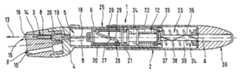
- the blood removal system 1 shown in FIG. 1comprises a puncture apparatus 2 and lancets 3 .
- the lancets 3are held in a revolver head 4 which can be attached exchangeably on the forward end 5 of the puncture apparatus 2 as part of its housing 6 .
- the revolver head 4is rotatable about an axis of rotation B to be positioned in a plurality of positions, in which, respectively, one lancet 3 is arranged coaxial with the main axis A of the puncture apparatus 2 .
- the lancet bodies 8 and the recesses 9in which the lancets 3 sit, are shaped relative to one another such that the walls of the recesses 9 form lancet guides 10 , by means of which the respective lancet 3 is guided on a predetermined puncture path (here, along the main axis A).
- a lancet drive 12is provided, which serves to move a lancet 3 with high speed in the puncturing direction 13 , until its tip 14 protrudes from an exit opening 15 , while the puncture apparatus 2 is pressed with a contact surface 16 surrounding the exit opening 15 against a body part (not shown). Thereby, a wound for removal of blood is produced in the body part.
- a respective lancet 3must be coupled with the lancet drive 12 .
- thisis achieved by means of a connecting rod, designated as a pushrod 18 .
- a holding element 19 with larger cross-sectionis provided, which for coupling of a lancet is inserted into a corresponding holding device 20 of the lancet body 8 .
- the holding device 20is formed, such that it engages the holding element 19 of the pushrod 18 in cooperation with the shape of the recess 9 , when the pushrod 18 is moved so far in the puncturing direction 13 that its front end contacts the lancet body and displaces the lancet 3 from the position shown in FIG.
- the lancet 3is “directly guided”, that is, it is located directly in a part of the housing 6 (in the present case, a magazine which contains a plurality of lancets) that forms the guide required during the puncturing movement.
- the embodiment of the lancet drive explained hereis suited in particular for such directly guided, magazined lancets.
- the lancet driveis permanently coupled with a lancet holder, into which a new lancet is manually inserted for each blood withdrawal.
- the lancet holderis guided by means of a housing part serving as a guide and thereby indirectly provides the required guide of the lancet on the puncturing path. This type of construction is described in the earlier publications cited above.
- the lancet drive 12comprises essentially a drive spring 22 , a cocking device 23 for tensioning of the drive spring 22 , and a drive rotor 24 that is driven by the drive spring 22 and is rotatable about axis A.
- the drive rotor 24is secured against axial displacement by means of a bearing pin 21 .
- an output-side coupling mechanism 25By means of an output-side coupling mechanism 25 , the rotational movement of the drive rotor 24 is converted into the puncturing movement which is by means of the pushrod 18 transferred to a lancet coupled thereon.
- the output-side coupling mechanism 25is in the shown device embodied as a curve controller with a control curve 27 and a control pin 28 travelling along the control curve 27 during the puncturing movement.
- the control curve 27is formed by a recess running about the periphery of the drive rotor 24 .
- the control pin 28is formed on a driving sleeve 30 , which surrounds the part of the drive rotor 24 provided with the control curve 27 .
- the driving sleeve 30is non-rotatably guided by means of a longitudinal groove (not shown), such that it can only carry out a translation movement.
- the pushrod 18is rigidly fixed.
- the output-side coupling mechanism 25is similar to the curve controllers described in U.S. Pat.
- the cocking device 23is designed according to the OWADAC principle.
- the end of the drive spring 22 facing away from the drive rotor 24is connected to a rotationally movable cocking element 33 , which, for tensioning of the drive spring 22 is rotatable in the same direction, in which the drive rotor 24 rotates during the driving phase, while the rotation of the drive rotor 24 is inhibited.
- the cocking element 33is arrested against a reverse rotation, so that the drive rotor 24 , after release of its rotation-inhibiting state, performs the rotational movement. This again is converted into the puncturing movement of the lancet 3 .
- the rotationally movable cocking element 33is connected via a rotary/sliding transmission 34 , which in the shown case is again embodied by means of a control curve 35 , with a translatory moveable actuator element 36 , which projects from the housing 6 .
- the actuator element 36is, in the shown situation, formed by a sliding sleeve 37 , which forms the rear part (with reference to the puncturing direction 13 ) of the housing 6 . It can be displaced forward in the direction of the main axis A of the puncture apparatus 2 against the force of a return spring 38 .
- the control curve 35is formed in a shaft 39 , which is nonrotatably connected with the cocking element 33 .
- FIG. 2shows an alternative embodiment of a blood removal system 1 according to the invention in five different movement phases. Functionally similar components are designated with the same reference numerals as used in FIG. 1 . The following differences exist:
- the movement position in FIG. 2 acorresponds with the base state of the lancet drive 12 .
- the drive spring 22is relaxed.
- the stop element 46rests against the forward locking catch 44 of the locking cam 42 .
- the drive rotor 24can rotate through an angle of rotation range, which corresponds to the distance between the forward locking catch 44 and the rear locking catch 45 of the locking cam 42 .
- This rangeis designated as the “preparation angle of rotation range.”
- This rotational movement of the drive rotor 24is achieved by means of a corresponding rotation of the actuator element 40 , by which a torque is directly transferred via the rotation spring 22 onto the drive rotor 24 . If the drive spring 22 was completely relaxed in the base state ( FIG. 2 a ), the components 40 , 22 , and 24 are commonly and uniformly rotated. If, in contrast, the drive spring 22 is in the base state ( FIG.
- the movement of the lancet drive in the preparation angle of rotation rangecan be used for preparation of the actual puncture process.
- itcan serve to couple the lancet drive with a lancet stored in a magazine.
- the coupling mechanism shown in FIG. 1 and specifically described in PCT/EP01/12527can be used.
- the preparation angle of rotation rangecan, however, also be used advantageously for other purposes, for example, to bring a lancet holder into a position, in which a used lancet is ejected and the lancet holder is prepared for receiving a new lancet.
- the stop element 46rests on the rear locking catch 45 . Therefore, the rotation of the drive rotor 24 in the direction of rotation R is inhibited.
- the spring 22is tensioned.
- the cocking element 33is locked by means of a locking mechanism not shown, such that, during the subsequent driving phase, it is arrested against a reverse rotation.
- the driving phase of the lancet drive 12 shown in FIG. 2 dis actuated by pivoting of the locking cam 42 into a position, in which its rear locking catch 45 releases the drive rotor 24 , while its forward locking catch 44 is pivoted into the rotational path of stop element 46 .
- the drive rotor 24carries out a fast rotational movement, driven by the highly tensioned drive spring 22 , which, by the output-side coupling mechanism 25 , is converted into a precisely executed and fast (therefore low-pain) puncture- and return movement of the lancet.
- FIG. 2 eshows the position of the maximum penetration of the lancet 3 , which corresponds with the lower reversal point of control curve 27 .
- the rotational movementis stopped by the forward locking catch 44 of the locking cam 42 , and the lancet drive is in the base state ( FIG. 2 a ).
- FIG. 3serves to explain in more detail how the described lancet drive can be used to realize different functions in two separate angle of rotation ranges.
- the shown sinus curverepresents a development of a control curve 27 in the plane of the drawing.
- the entire angle of rotation range of the OWADAC drive (360°)is subdivided into a preparation angle of rotation range 51 (in the illustrated case, 130°) and into a puncture angle of rotation range 52 (230°).
- the slope of the control curve 27is small. This causes a slow movement with relative strong force.
- a protective film covering the lancet receiving recesses 9 at the rear of the revolver head 4is pierced by means of the front end of the pushrod 18 ( FIG. 1 ).
- the pushrodimpinges the end of the lancet 3 at control curve position P 2 (at 100° and approximately 8.5 mm movement path).
- the retaining element 19 of the pushrod 18penetrates into the holding device 20 of the lancet 3 , whereby the lancet 3 is coupled to the lancet drive 12 .
- the control pin 28is located in position P 3 . After cocking and release of the inhibition, the drive rotor 24 rotates through the angle of rotation range 52 , whereby the puncture and reverse movement proceeds.
- the axis of the drive rotorruns parallel to the puncture direction (as shown in FIGS. 1 and 2 ).
- a drive rotorwhose axis runs perpendicular to the puncture direction and the main axis of the puncture apparatus can be used.
- the output-side coupling mechanism 25can, for example, be formed by a con-rod drive (see U.S. Pat. No. 4,924,879).
- the force transfer from an actuator element moving translatory in the puncture direction onto a rotatable cocking element that is coaxial to the drive rotorcan take place, for example, by means of a gear rod and a pinion coupled with the cocking element.
- FIGS. 4 through 9Such an embodiment of a blood removal system 1 is shown in FIGS. 4 through 9 .
- One element of the lancet drive 12 in this embodimentis a drive module 55 .
- components of the drive module 55are the drive rotor 24 and the rotatably moveable cocking element 33 , which are rotatably about a common axis C running perpendicular to the puncture direction 13 and to the longitudinal axis of the puncture apparatus 2 .
- a translatory moving actuator element 36is moved in the puncture direction by means of an actuator button 56 .
- a gear rod 57is a component of actuator element 36 and drives a pinion 58 that is coaxial to the cocking element 33 .
- Pinion 58is connected with cocking element 33 via a free wheel 59 ( FIG. 5 ) in such a manner that both parts are coupled with one another during the cocking movement (movement of the actuator element 36 in the puncture direction), while being uncoupled during the return movement of the actuator element 36 .
- the free wheel 59is realized by means of two elastic tongues 60 , which are connected with the pinion 58 .
- Tongues 60are located in a recess 61 of cocking element 33 facing away from drive rotor 24 .
- the recess 61includes stops 62 , on which the ends of the tongues rest in the coupling direction of rotation (in FIG. 5 , clockwise), while in the reverse direction, pinion 58 can rotate freely relative to cocking element 33 .
- the drive spring 22is tensioned.
- the drive spring 22is formed as a spiral spring and is located in a recess 64 of the rotatably moveable cocking element 33 facing the drive rotor 24 .
- the output-side coupling mechanism 25again includes a control curve 27 , which is formed by a recess 29 in drive rotor 24 .
- the control curve 27has, in the case shown, the shape of a circle eccentric to the axis C.
- a control pin 28FIG. 8
- the lancet holder 65has elastic arms 66 and a stop element 67 , whose shape is adapted to the corresponding shape of a lancet, such that the latter is held in a reproducible longitudinal position in the holder 65 .
- This design principleis known (for example, from U.S. Pat. No. 5,318,584) and need not be explained in more detail.
- the shown embodimentcomprises a separating disc 68 made, for example, of metal, which lies on a plateau of the drive rotor 24 in such a manner that the circumferential gap remains. It has a width required for accommodating the lancet holder 65 between disc 68 and the parts of the rotor 24 that are radially outward from control curve 27 .
- the cocking- and puncture movementagain includes the phases explained with reference to FIGS. 1 through 3 :
Landscapes
- Health & Medical Sciences (AREA)
- Life Sciences & Earth Sciences (AREA)
- Engineering & Computer Science (AREA)
- Physics & Mathematics (AREA)
- Molecular Biology (AREA)
- General Health & Medical Sciences (AREA)
- Biophysics (AREA)
- Biomedical Technology (AREA)
- Heart & Thoracic Surgery (AREA)
- Medical Informatics (AREA)
- Hematology (AREA)
- Surgery (AREA)
- Animal Behavior & Ethology (AREA)
- Pathology (AREA)
- Public Health (AREA)
- Veterinary Medicine (AREA)
- Manufacturing & Machinery (AREA)
- Dermatology (AREA)
- Geometry (AREA)
- Measurement Of The Respiration, Hearing Ability, Form, And Blood Characteristics Of Living Organisms (AREA)
- External Artificial Organs (AREA)
- Investigating Or Analysing Biological Materials (AREA)
Abstract
Description
- During the cocking phase, the cocking element is rotated, while simultaneously, the rotation of the drive rotor is inhibited.
- During the driving phase, the cocking element is fixed against a reverse rotation, so that the drive rotor, after termination of the inhibition, can perform a rotational movement, which is converted by means of the output-side coupling mechanism into a corresponding translation movement of the lancet.
- In order to simplify the drawing and to allow a good recognition of the functions of the invention, the mechanism for coupling exchangeable lancets is omitted. Instead, the
blood removal system 1 shown inFIG. 2 has alancet 3 rigidly connected with the drivingsleeve 30. - For cocking of the
lancet drive 12, arotatable actuator element 40 is provided, which projects from the rear end of thehousing 6. Theactuator element 40 is fixedly connected to the cockingelement 33. - In the embodiment shown a
locking cam 42 is provided as a constructive element, by means of which the required stoppage of the rotation of the drive rotor during the cocking phase is achieved. By pivoting about anaxis 43 it can be brought into two different positions, in which, respectively, one of two lockingcatches stop element 46 provided on thedrive rotor 24. The first locking catch, with reference to the rotational direction R of thedrive rotor 24, is designated as theforward locking catch 44 and the second as therear locking catch 45.
- In order to simplify the drawing and to allow a good recognition of the functions of the invention, the mechanism for coupling exchangeable lancets is omitted. Instead, the
- During cocking, the rotatably
moveable cocking element 33 rotates in a specified direction (inFIG. 4 , clockwise), wherebyspring 22 is tensioned, while the rotation of the drive rotor24 (by means of a release mechanism, not shown, acting on a locking pin70 (FIG. 6 )) is inhibited. - In a puncture phase,
drive spring 22 drives drive rotor24 (after release of the stoppage acting on the pin70), while, at the same time, the cockingelement 33 is arrested (for example, by means of an elastic catch, not shown, engaging in a recess of the cocking element33) against a reverse rotation.
- During cocking, the rotatably
- A translatory movable actuator element36 (
FIG. 1 ) can, of course, be designed in such a manner that the lancet drive is tensioned not by means of a forward movement of the actuator element (in the puncture direction13), but rather by a reverse movement (that is, through pulling instead of pressing). - As a
drive spring 22, basically each rotationally elastic spring element is suited. This includes, in particular, a torsion spring, or a torsion bar. - In the embodiment shown (
FIG. 2 ), the inhibition of thedrive rotor 24 is coupled with a manually operated release. Alternatively, however, it is possible to use a self-releasing inhibition, which releases the rotational movement of the drive rotor, when the torque transferred from thedrive spring 22 to thedrive rotor 24 exceeds a defined value. In combination with an actuator element that is translatory moveable in the puncture direction for the cocking movement, a lancet drive results, with which the entire movement process runs automatically upon pressing of the actuation element.
- A translatory movable actuator element36 (
Claims (64)
Applications Claiming Priority (3)
| Application Number | Priority Date | Filing Date | Title |
|---|---|---|---|
| DE10223558.9 | 2002-05-28 | ||
| DE10223558ADE10223558A1 (en) | 2002-05-28 | 2002-05-28 | System useful in withdrawing blood for diagnostic purposes, has housing, lancet guide and lancet drive provided with drive spring, cocking device, drive rotor and outputs side coupling mechanism |
| DE10223558 | 2002-05-28 |
Publications (2)
| Publication Number | Publication Date |
|---|---|
| US20040092996A1 US20040092996A1 (en) | 2004-05-13 |
| US7223276B2true US7223276B2 (en) | 2007-05-29 |
Family
ID=29432349
Family Applications (1)
| Application Number | Title | Priority Date | Filing Date |
|---|---|---|---|
| US10/445,606Expired - LifetimeUS7223276B2 (en) | 2002-05-28 | 2003-05-27 | Blood removal system |
Country Status (8)
| Country | Link |
|---|---|
| US (1) | US7223276B2 (en) |
| EP (3) | EP2082685B1 (en) |
| JP (2) | JP3746772B2 (en) |
| AT (1) | ATE429174T1 (en) |
| CA (2) | CA2429594C (en) |
| DE (2) | DE10223558A1 (en) |
| DK (1) | DK1384438T3 (en) |
| ES (3) | ES2426718T3 (en) |
Cited By (34)
| Publication number | Priority date | Publication date | Assignee | Title |
|---|---|---|---|---|
| US20040267300A1 (en)* | 2003-06-27 | 2004-12-30 | Mace Chad Harold | Lancing device |
| US20070060937A1 (en)* | 2005-08-30 | 2007-03-15 | Liu Chen H | Safety needle holder |
| US20070233167A1 (en)* | 2004-09-04 | 2007-10-04 | Thomas Weiss | Lancing apparatus for producing a puncture wound |
| US20080077167A1 (en)* | 2006-06-15 | 2008-03-27 | Abbott Diabetes Care Inc. | Lancing Devices Having Depth Adjustment Assembly |
| US20080208079A1 (en)* | 2005-09-03 | 2008-08-28 | Heinz-Michael Hein | Method for creating a puncture wound and handheld apparatus suitable therefor |
| US20090012428A1 (en)* | 2005-12-05 | 2009-01-08 | Uwe Kramer | Reusable piercing aid and method for carrying out a piercing movement by means of a reusable piercing aid |
| EP2016899A1 (en) | 2007-07-17 | 2009-01-21 | F.Hoffmann-La Roche Ag | Method and device for extracting body fluids |
| US20090088792A1 (en)* | 2007-10-02 | 2009-04-02 | Tyco Healthcare Group Lp | Articulating Surgical Instrument |
| US20100042131A1 (en)* | 2008-08-14 | 2010-02-18 | Abbott Diabetes Care Inc. | Cocking mechanism for lancing device |
| US20100145376A1 (en)* | 2007-05-10 | 2010-06-10 | Ahmet Konya | Puncturing system and lancet carrier tape |
| US20100160943A1 (en)* | 2008-12-18 | 2010-06-24 | Facet Technologies, Llc | Lancing device and lancet |
| EP2213231A1 (en) | 2009-01-30 | 2010-08-04 | Roche Diagnostics GmbH | Integrated body fluid meter and lancing device |
| US20100256526A1 (en)* | 2009-04-03 | 2010-10-07 | Herbert Harttig | Apparatus for acquiring and analyzing a blood sample |
| EP2311373A1 (en) | 2009-10-15 | 2011-04-20 | Roche Diagnostics GmbH | Piercing system for removal of a body fluid |
| US20110105949A1 (en)* | 2008-06-25 | 2011-05-05 | Neodynamics Ab | Core biopsy arrangement |
| DE102011015758B4 (en)* | 2011-03-31 | 2013-08-01 | Gerresheimer Regensburg Gmbh | Lancing device with rotary element |
| US8758381B2 (en) | 2010-12-04 | 2014-06-24 | Roche Diagnostics Operations, Inc. | Lancet device with optionally reusable lancets stored in a magazine |
| US9844331B2 (en) | 2011-12-15 | 2017-12-19 | Facet Technologies, Llc | Latch mechanism for preventing lancet oscillation in a lancing device |
| US10085681B2 (en) | 2012-04-11 | 2018-10-02 | Facet Technologies, Llc | Lancing device with moving pivot depth adjust |
| US10092231B2 (en) | 2012-09-13 | 2018-10-09 | Facet Technologies, Llc | Push-to-charge mechanism for lancing device |
| US10456069B2 (en) | 2012-04-12 | 2019-10-29 | Facet Technologies, Llc | Lancing device with side activated charge and eject mechanisms |
| US10660556B2 (en) | 2013-06-13 | 2020-05-26 | Roche Diabetes Care, Inc. | Body fluid sampling element |
| US11134896B2 (en) | 2017-06-23 | 2021-10-05 | Dexcom, Inc. | Transcutaneous analyte sensors, applicators therefor, and associated methods |
| US11160926B1 (en) | 2007-10-09 | 2021-11-02 | Dexcom, Inc. | Pre-connected analyte sensors |
| US11166657B2 (en) | 2015-12-30 | 2021-11-09 | Dexcom, Inc. | Transcutaneous analyte sensor systems and methods |
| US11331022B2 (en) | 2017-10-24 | 2022-05-17 | Dexcom, Inc. | Pre-connected analyte sensors |
| US11350862B2 (en) | 2017-10-24 | 2022-06-07 | Dexcom, Inc. | Pre-connected analyte sensors |
| US11627900B2 (en) | 2003-12-05 | 2023-04-18 | Dexcom, Inc. | Analyte sensor |
| USD1036676S1 (en) | 2018-06-22 | 2024-07-23 | Dexcom, Inc. | Wearable medical monitoring device |
| US12239463B2 (en) | 2020-08-31 | 2025-03-04 | Abbott Diabetes Care Inc. | Systems, devices, and methods for analyte sensor insertion |
| US12268496B2 (en) | 2017-01-23 | 2025-04-08 | Abbott Diabetes Care Inc. | Systems, devices and methods for analyte sensor insertion |
| US12274548B2 (en) | 2006-10-23 | 2025-04-15 | Abbott Diabetes Care Inc. | Sensor insertion devices and methods of use |
| US12318200B2 (en) | 2008-11-07 | 2025-06-03 | Dexcom, Inc. | Analyte sensor |
| US12408847B2 (en) | 2018-06-07 | 2025-09-09 | Abbott Diabetes Care Inc. | Focused sterilization and sterilized sub-assemblies for analyte monitoring systems |
Families Citing this family (31)
| Publication number | Priority date | Publication date | Assignee | Title |
|---|---|---|---|---|
| JP4296035B2 (en)* | 2003-05-21 | 2009-07-15 | アークレイ株式会社 | Puncture device |
| DE10336933B4 (en) | 2003-08-07 | 2007-04-26 | Roche Diagnostics Gmbh | Blood Collection system |
| US9066688B2 (en) | 2004-05-07 | 2015-06-30 | Becton, Dickinson And Company | Contact activated lancet device |
| US9380975B2 (en) | 2004-05-07 | 2016-07-05 | Becton, Dickinson And Company | Contact activated lancet device |
| DE102004037270B4 (en)* | 2004-07-31 | 2008-01-31 | Roche Diagnostics Gmbh | Blood collection system for taking blood for diagnostic purposes |
| EP1815792B1 (en)* | 2004-10-25 | 2016-06-01 | ARKRAY, Inc. | Lancet and lancet device with the same |
| DE102004059491B4 (en)* | 2004-12-10 | 2008-11-06 | Roche Diagnostics Gmbh | Lancet device for creating a puncture wound and lancet drive assembly |
| DE102004064136B4 (en)* | 2004-12-10 | 2013-03-21 | Roche Diagnostics Gmbh | Lancet device for making puncture wound for taking out body fluid for diagnostic purpose has reference element coupling mechanism with lancet drive for moving reference element and cam which is driven by cam rider |
| DE102005005017A1 (en) | 2005-02-03 | 2006-08-17 | Roche Diagnostics Gmbh | Electromechanical lancing device for obtaining liquid samples |
| PL2425776T3 (en)* | 2005-04-07 | 2013-12-31 | Becton Dickinson Co | Lancet device |
| EP1743577A1 (en)* | 2005-06-23 | 2007-01-17 | Roche Diagnostics GmbH | Hand-held apparatus for the analysis of bodily fluids |
| KR100705137B1 (en)* | 2005-11-15 | 2007-04-09 | 현대자동차주식회사 | How to determine driving mode of hybrid vehicle |
| EP1852069B1 (en)* | 2006-05-04 | 2015-06-17 | Roche Diagnostics GmbH | System for sampling blood from a body part |
| WO2008064333A2 (en)* | 2006-11-21 | 2008-05-29 | Stat Medical Devices, Inc. | Lancet device utilizing a revolver-type cartridge, revolver-type cartridge, and method of making and/or using the cartridge and the lancet device |
| DE102007063661B4 (en)* | 2007-03-05 | 2012-03-15 | Gerresheimer Regensburg Gmbh | Lancing device with torsion spring |
| EP1974667A1 (en)* | 2007-03-29 | 2008-10-01 | Roche Diagnostics GmbH | Piercing system |
| GB2451840B (en) | 2007-08-14 | 2012-01-18 | Owen Mumford Ltd | Lancing devices |
| WO2009046957A2 (en)* | 2007-10-08 | 2009-04-16 | Roche Diagnostics Gmbh | Analysis system for automatic skin prick analysis |
| KR20110017063A (en)* | 2009-08-13 | 2011-02-21 | (주)마이티시스템 | Lancet block and lancet actuator |
| EP2382921A1 (en) | 2010-04-30 | 2011-11-02 | Roche Diagnostics GmbH | Lancing device with automatic disengagement |
| US9167992B2 (en) | 2010-11-03 | 2015-10-27 | Roche Diabetes Care, Inc. | Lancet drive system depth control method and test strip location methods |
| KR101172855B1 (en)* | 2010-12-14 | 2012-08-20 | 주식회사 아이센스 | Percussion structure of lancing device |
| US20130211289A1 (en) | 2012-01-25 | 2013-08-15 | Tasso, Inc. | Handheld Device for Drawing, Collecting, and Analyzing Bodily Fluid |
| JP6420764B2 (en)* | 2012-08-27 | 2018-11-07 | ファセット テクノロジーズ エルエルシーFacet Technologies, LLC | Twist loading mechanism of puncture device |
| USD739011S1 (en)* | 2013-03-15 | 2015-09-15 | Eli Lilly And Company | Automatic injection device |
| EP2823762B1 (en) | 2013-07-08 | 2015-08-19 | Roche Diagniostics GmbH | Lancing actuator |
| JP6640830B2 (en) | 2014-07-18 | 2020-02-05 | ベクトン・ディキンソン・アンド・カンパニーBecton, Dickinson And Company | Lancet device for removing first droplet |
| CN106999120B (en) | 2014-08-01 | 2021-05-14 | 塔索公司 | Devices, systems, and methods for gravity-enhanced microfluidic collection, handling, and delivery of liquids |
| CA3009328C (en) | 2015-12-21 | 2024-03-05 | Tasso, Inc. | Devices, systems and methods for actuation and retraction in fluid collection |
| CN109984815B (en)* | 2017-12-31 | 2022-05-10 | 江苏风和医疗器材股份有限公司 | Coreless puncture outfit |
| JP7460607B2 (en) | 2018-09-14 | 2024-04-02 | タッソ インコーポレイテッド | Body fluid collection devices and related methods |
Citations (104)
| Publication number | Priority date | Publication date | Assignee | Title |
|---|---|---|---|---|
| US3030959A (en) | 1959-09-04 | 1962-04-24 | Praemeta | Surgical lancet for blood sampling |
| US3244317A (en) | 1962-10-26 | 1966-04-05 | Philip Morris Inc | Blade dispenser |
| GB1085141A (en) | 1964-06-09 | 1967-09-27 | Roehr Products Company Inc | Integral lancet and package |
| US3696915A (en) | 1970-11-12 | 1972-10-10 | Colgate Palmolive Co | Blade dispenser |
| US3833146A (en) | 1973-02-22 | 1974-09-03 | Philip Morris Inc | Magazine holding razor blade cartridges in floating manner |
| US4139011A (en) | 1975-12-19 | 1979-02-13 | Benoit Jean L P M | Device for driving a needle into a patient |
| DE2803345B1 (en) | 1978-01-26 | 1979-06-13 | Emil Eisinger | Blood sampling device |
| US4203446A (en) | 1976-09-24 | 1980-05-20 | Hellige Gmbh | Precision spring lancet |
| US4388925A (en) | 1981-03-23 | 1983-06-21 | Becton Dickinson And Company | Automatic retractable lancet assembly |
| US4416279A (en) | 1981-06-19 | 1983-11-22 | Lindner James A | Capillary blood sampling device |
| US4442836A (en) | 1980-03-22 | 1984-04-17 | Clinicon Mannheim Gmbh | Blood lancet device |
| US4449529A (en) | 1981-11-18 | 1984-05-22 | Becton Dickinson And Company | Automatic retractable lancet assembly |
| US4469110A (en) | 1981-06-25 | 1984-09-04 | Slama Gerard J | Device for causing a pinprick to obtain and to test a drop of blood |
| US4527561A (en) | 1981-03-23 | 1985-07-09 | Becton, Dickinson And Company | Automatic retractable lancet assembly |
| US4539988A (en) | 1983-07-05 | 1985-09-10 | Packaging Corporation International | Disposable automatic lancet |
| WO1985004089A1 (en) | 1984-03-09 | 1985-09-26 | Geoffrey Charles Palmer | Apparatus for sampling a fluid |
| US4577630A (en) | 1984-02-14 | 1986-03-25 | Becton, Dickinson And Co. | Reusable breach loading target pressure activated lancet firing device |
| US4624253A (en) | 1985-01-18 | 1986-11-25 | Becton, Dickinson And Company | Lancet |
| US4635633A (en) | 1984-12-17 | 1987-01-13 | Hufnagle Douglas R | Combination sterile pad support and lancet |
| US4653513A (en) | 1985-08-09 | 1987-03-31 | Dombrowski Mitchell P | Blood sampler |
| US4677979A (en) | 1984-09-20 | 1987-07-07 | Becton, Dickinson And Company | Lancet |
| US4712548A (en) | 1980-04-23 | 1987-12-15 | Enstroem Hans | Blood lancing device |
| US4715374A (en) | 1986-11-14 | 1987-12-29 | Medicore, Inc. | Disposable automatic lancet |
| US4735203A (en) | 1986-12-12 | 1988-04-05 | Ryder International Corporation | Retractable lancet |
| US4794926A (en) | 1986-11-24 | 1989-01-03 | Invictus, Inc. | Lancet cartridge |
| US4817603A (en) | 1986-07-30 | 1989-04-04 | Glyme Valley Technology Limited | Lancet device |
| US4821878A (en) | 1986-10-08 | 1989-04-18 | Prd Corporation | Round dispenser for sutures |
| US4844095A (en) | 1987-12-14 | 1989-07-04 | Medicore, Inc. | Automatic lancet device |
| US4856515A (en) | 1986-06-19 | 1989-08-15 | Turner Robert C | Automatic lancet |
| US4858607A (en) | 1987-10-16 | 1989-08-22 | Pavel Jordan & Associates | Plastic device for injection and obtaining blood samples |
| US4860937A (en) | 1987-03-31 | 1989-08-29 | Friedheim Pickhan | Device for driving in nails for hanging pictures and similar articles |
| US4869249A (en) | 1987-05-01 | 1989-09-26 | Owen Mumford Limited | Blood sampling devices |
| US4889117A (en) | 1989-02-17 | 1989-12-26 | Stevens Peter A | Disposable lancet |
| US4892097A (en) | 1988-02-09 | 1990-01-09 | Ryder International Corporation | Retractable finger lancet |
| US4895147A (en) | 1988-10-28 | 1990-01-23 | Sherwood Medical Company | Lancet injector |
| US4924879A (en) | 1988-10-07 | 1990-05-15 | Brien Walter J O | Blood lancet device |
| DE3842317A1 (en) | 1988-12-16 | 1990-06-21 | Medico S A | Arrangement with a sterile cannula |
| US4976724A (en) | 1989-08-25 | 1990-12-11 | Lifescan, Inc. | Lancet ejector mechanism |
| US4983178A (en) | 1988-11-14 | 1991-01-08 | Invictus, Inc. | Lancing device |
| US4990154A (en) | 1989-06-19 | 1991-02-05 | Miles Inc. | Lancet assembly |
| US4994068A (en) | 1989-11-24 | 1991-02-19 | Unidex, Inc. | Combination sterile pad support and lancet containing lancet disposal element |
| US4995402A (en) | 1988-10-12 | 1991-02-26 | Thorne, Smith, Astill Technologies, Inc. | Medical droplet whole blood and like monitoring |
| US4998452A (en) | 1988-03-25 | 1991-03-12 | Blum Kurt E | Cartridge and magazine apparatus for storage and automatic feed of screw fasteners |
| US5026388A (en) | 1989-09-26 | 1991-06-25 | Ingalz Thomas J | Single-use skin puncture device |
| US5029583A (en) | 1986-07-22 | 1991-07-09 | Personal Diagnostics, Inc. | Optical analyzer |
| US5035704A (en) | 1989-03-07 | 1991-07-30 | Lambert Robert D | Blood sampling mechanism |
| US5070886A (en) | 1988-01-22 | 1991-12-10 | Safety Diagnostice, Inc. | Blood collection and testing means |
| US5100428A (en) | 1989-12-12 | 1992-03-31 | Owen Mumford Limited | Disposable two part body pricker |
| US5100427A (en) | 1989-11-04 | 1992-03-31 | Owen Mumford Limited | Disposable lancet device |
| US5105823A (en) | 1990-04-05 | 1992-04-21 | Blum Alvin S | Shielded replaceable lancet blade assembly |
| US5120311A (en) | 1989-11-01 | 1992-06-09 | Medical Safety Products, Inc. | Blood collection tube holder |
| DE9205278U1 (en) | 1992-04-16 | 1992-06-25 | Arta Plast AB, Tyresö | Lancet device for puncturing the skin |
| US5133730A (en) | 1991-05-15 | 1992-07-28 | International Technidyne Corporation | Disposable-retractable finger stick device |
| US5147375A (en) | 1991-05-31 | 1992-09-15 | Ann Sullivan | Safety finger prick instrument |
| US5152775A (en) | 1990-10-04 | 1992-10-06 | Norbert Ruppert | Automatic lancet device and method of using the same |
| WO1993000044A1 (en) | 1991-06-21 | 1993-01-07 | Novo Nordisk A/S | Blood sampler |
| EP0199484B1 (en) | 1985-04-08 | 1993-03-17 | Audio Bionics Inc | Medical system |
| US5196025A (en) | 1990-05-21 | 1993-03-23 | Ryder International Corporation | Lancet actuator with retractable mechanism |
| US5207699A (en) | 1989-10-30 | 1993-05-04 | Coe Frederick L | Lancet handling and disposal assembly |
| EP0565970A1 (en) | 1992-04-13 | 1993-10-20 | Roche Diagnostics GmbH | Blood lancet device for obtaining blood samples for diagnosis purpose |
| US5269800A (en) | 1992-12-10 | 1993-12-14 | Davis Manufacturing Systems Inc. | Blood lancing device |
| EP0589186A1 (en) | 1992-08-28 | 1994-03-30 | Apls Co., Ltd. | Lancet |
| US5304193A (en) | 1993-08-12 | 1994-04-19 | Sam Zhadanov | Blood lancing device |
| US5304192A (en) | 1992-01-16 | 1994-04-19 | Sherwood Medical Company | Lancet with locking cover |
| US5314442A (en) | 1992-10-26 | 1994-05-24 | Apls Co., Ltd. | Blood collecting apparatus |
| US5356420A (en) | 1992-08-03 | 1994-10-18 | Przedsiebiorstwo Zagraniczne Htl | Device for puncturing |
| US5366470A (en) | 1991-11-12 | 1994-11-22 | Ramel Urs A | Lancet device |
| US5397334A (en) | 1994-01-11 | 1995-03-14 | Sherwood Medical Company | Distal movement limiting assembly for finger stick device |
| US5439473A (en) | 1993-12-13 | 1995-08-08 | Modulohm A/S | Safety lancet |
| US5464418A (en) | 1993-12-09 | 1995-11-07 | Schraga; Steven | Reusable lancet device |
| US5478345A (en) | 1994-08-19 | 1995-12-26 | United States Surgical Corporation | Mechanism for endoscopic suturing device |
| US5487748A (en) | 1992-04-01 | 1996-01-30 | Owen Mumford Limited | Blood sampling device |
| WO1996002189A1 (en) | 1994-07-13 | 1996-02-01 | Owen Mumford Limited | Blood sampling device |
| US5514152A (en) | 1994-08-16 | 1996-05-07 | Specialized Health Products, Inc. | Multiple segment encapsulated medical lancing device |
| US5527334A (en) | 1994-05-25 | 1996-06-18 | Ryder International Corporation | Disposable, retractable lancet |
| US5531763A (en) | 1994-10-07 | 1996-07-02 | United States Surgical Corporation | Suture cinching apparatus |
| US5554166A (en) | 1993-06-21 | 1996-09-10 | Boehringer Mannheim Gmbh | Blood lancet device for withdrawing blood for diagnostic purposes |
| US5628765A (en) | 1994-11-29 | 1997-05-13 | Apls Co., Ltd. | Lancet assembly |
| US5632410A (en) | 1995-04-17 | 1997-05-27 | Bayer Corporation | Means of handling multiple sensors in a glucose monitoring instrument system |
| US5636640A (en) | 1995-02-06 | 1997-06-10 | Volunteers For Medical Engineering | Liquid sampling and test apparatus |
| US5643306A (en) | 1996-03-22 | 1997-07-01 | Stat Medical Devices Inc. | Disposable lancet |
| US5662669A (en) | 1992-01-24 | 1997-09-02 | Bloom & Kreten | Combination guarded surgical scalpel and blade stripper |
| WO1998014125A1 (en) | 1996-10-02 | 1998-04-09 | Specialized Health Products, Inc. | Lancet apparatus and methods |
| US5829589A (en) | 1997-09-12 | 1998-11-03 | Becton Dickinson And Company | Pen needle magazine dispenser |
| US5908434A (en) | 1998-02-13 | 1999-06-01 | Schraga; Steven | Lancet device |
| US5951582A (en) | 1998-05-22 | 1999-09-14 | Specialized Health Products, Inc. | Lancet apparatus and methods |
| US5984940A (en) | 1997-05-29 | 1999-11-16 | Atrion Medical Products, Inc. | Lancet device |
| US6056765A (en) | 1997-06-24 | 2000-05-02 | Bajaj; Ratan | Lancet device |
| US6109740A (en)* | 1996-12-09 | 2000-08-29 | Sony Corporation | Method and apparatus for supplying ink to a printer |
| WO2001000090A1 (en) | 1999-06-30 | 2001-01-04 | Nederlandse Organisatie Voor Toegepast- Natuurwetenschappelijk Onderzoek Tno | Pricking device, carrier and cassette comprising a plurality of lancets |
| US6358265B1 (en) | 2000-07-18 | 2002-03-19 | Specialized Health Products, Inc. | Single-step disposable safety lancet apparatus and methods |
| WO2002036010A1 (en) | 2000-10-31 | 2002-05-10 | Roche Diagnostics Gmbh | System for withdrawing blood |
| JP2002143131A (en)* | 2000-11-14 | 2002-05-21 | Mitsubishi Pencil Co Ltd | Lancet injector |
| US6409740B1 (en) | 1999-10-09 | 2002-06-25 | Roche Diagnostics Gmbh | Blood lancet system for withdrawing blood for diagnostic purposes |
| US6419661B1 (en) | 1999-03-05 | 2002-07-16 | Roche Diagnostics Gmbh | Device for withdrawing blood for diagnostic applications |
| US6472220B1 (en) | 1997-12-04 | 2002-10-29 | Agilent Technologies, Inc. | Method of using cassette of lancet cartridges for sampling blood |
| US6514270B1 (en) | 2000-11-10 | 2003-02-04 | Steven Schraga | Single use lancet device |
| US20030050656A1 (en) | 2000-11-10 | 2003-03-13 | Steven Schraga | Single use lancet device |
| US20040039407A1 (en) | 2002-04-29 | 2004-02-26 | Steven Schraga | Lancet device |
| US6719771B1 (en) | 1999-06-19 | 2004-04-13 | Owen Mumford Limited | Blood sampling device |
| US20040127928A1 (en)* | 2002-10-15 | 2004-07-01 | Whitson Robert C. | Lancing device |
| US20050090850A1 (en)* | 2003-07-08 | 2005-04-28 | Thoes Bruno R. | Blood withdrawal system |
| US20050131441A1 (en)* | 2003-12-16 | 2005-06-16 | Toshiaki Iio | Lancet for blood collection and puncture needle unit |
| EP0931507B1 (en) | 1998-01-22 | 2006-07-05 | Terumo Kabushiki Kaisha | Body-fluid inspection device |
Family Cites Families (1)
| Publication number | Priority date | Publication date | Assignee | Title |
|---|---|---|---|---|
| US4988452A (en)* | 1988-06-09 | 1991-01-29 | The Procter & Gamble Company | Liquid automatic dishwashing detergent compositions containing bleach-stable nonionic surfactant |
- 2002
- 2002-05-28DEDE10223558Apatent/DE10223558A1/ennot_activeCeased
- 2003
- 2003-05-03EPEP09005455.2Apatent/EP2082685B1/ennot_activeExpired - Lifetime
- 2003-05-03DKDK03010078Tpatent/DK1384438T3/enactive
- 2003-05-03DEDE50311444Tpatent/DE50311444D1/ennot_activeExpired - Lifetime
- 2003-05-03EPEP03010078Apatent/EP1384438B1/ennot_activeExpired - Lifetime
- 2003-05-03ESES10005092Tpatent/ES2426718T3/ennot_activeExpired - Lifetime
- 2003-05-03EPEP10005092.1Apatent/EP2213229B1/ennot_activeExpired - Lifetime
- 2003-05-03ATAT03010078Tpatent/ATE429174T1/enactive
- 2003-05-03ESES09005455.2Tpatent/ES2473628T3/ennot_activeExpired - Lifetime
- 2003-05-03ESES03010078Tpatent/ES2324212T3/ennot_activeExpired - Lifetime
- 2003-05-26CACA2429594Apatent/CA2429594C/ennot_activeExpired - Lifetime
- 2003-05-26CACA2708807Apatent/CA2708807C/ennot_activeExpired - Lifetime
- 2003-05-27JPJP2003149780Apatent/JP3746772B2/ennot_activeExpired - Lifetime
- 2003-05-27USUS10/445,606patent/US7223276B2/ennot_activeExpired - Lifetime
- 2005
- 2005-08-18JPJP2005237506Apatent/JP2006006969A/enactivePending
Patent Citations (118)
| Publication number | Priority date | Publication date | Assignee | Title |
|---|---|---|---|---|
| US3030959A (en) | 1959-09-04 | 1962-04-24 | Praemeta | Surgical lancet for blood sampling |
| US3244317A (en) | 1962-10-26 | 1966-04-05 | Philip Morris Inc | Blade dispenser |
| GB1085141A (en) | 1964-06-09 | 1967-09-27 | Roehr Products Company Inc | Integral lancet and package |
| US3696915A (en) | 1970-11-12 | 1972-10-10 | Colgate Palmolive Co | Blade dispenser |
| US3833146A (en) | 1973-02-22 | 1974-09-03 | Philip Morris Inc | Magazine holding razor blade cartridges in floating manner |
| US4139011A (en) | 1975-12-19 | 1979-02-13 | Benoit Jean L P M | Device for driving a needle into a patient |
| US4203446A (en) | 1976-09-24 | 1980-05-20 | Hellige Gmbh | Precision spring lancet |
| DE2803345B1 (en) | 1978-01-26 | 1979-06-13 | Emil Eisinger | Blood sampling device |
| US4442836A (en) | 1980-03-22 | 1984-04-17 | Clinicon Mannheim Gmbh | Blood lancet device |
| EP0036443B1 (en) | 1980-03-22 | 1986-03-05 | Roche Diagnostics GmbH | Lancet apparatus for withdrawing blood for diagnostic purposes |
| US4712548A (en) | 1980-04-23 | 1987-12-15 | Enstroem Hans | Blood lancing device |
| US4738261A (en) | 1980-04-23 | 1988-04-19 | Enstroem Hans | Medical lancet means |
| US4553541A (en) | 1981-03-23 | 1985-11-19 | Becton, Dickinson And Co. | Automatic retractable lancet assembly |
| US4388925A (en) | 1981-03-23 | 1983-06-21 | Becton Dickinson And Company | Automatic retractable lancet assembly |
| US4527561A (en) | 1981-03-23 | 1985-07-09 | Becton, Dickinson And Company | Automatic retractable lancet assembly |
| US4535769A (en) | 1981-03-23 | 1985-08-20 | Becton, Dickinson And Company | Automatic retractable lancet assembly |
| US4416279A (en) | 1981-06-19 | 1983-11-22 | Lindner James A | Capillary blood sampling device |
| US4469110A (en) | 1981-06-25 | 1984-09-04 | Slama Gerard J | Device for causing a pinprick to obtain and to test a drop of blood |
| FR2508305B1 (en) | 1981-06-25 | 1986-04-11 | Slama Gerard | DEVICE FOR CAUSING A LITTLE BITE TO COLLECT A BLOOD DROP |
| EP0081665B1 (en) | 1981-11-18 | 1986-04-16 | Becton Dickinson and Company | Automatic retractable lancet assembly |
| US4449529A (en) | 1981-11-18 | 1984-05-22 | Becton Dickinson And Company | Automatic retractable lancet assembly |
| US4539988A (en) | 1983-07-05 | 1985-09-10 | Packaging Corporation International | Disposable automatic lancet |
| US4577630A (en) | 1984-02-14 | 1986-03-25 | Becton, Dickinson And Co. | Reusable breach loading target pressure activated lancet firing device |
| WO1985004089A1 (en) | 1984-03-09 | 1985-09-26 | Geoffrey Charles Palmer | Apparatus for sampling a fluid |
| US4677979A (en) | 1984-09-20 | 1987-07-07 | Becton, Dickinson And Company | Lancet |
| EP0178384B1 (en) | 1984-09-20 | 1991-11-06 | Becton Dickinson and Company | Lancet |
| EP0204892B1 (en) | 1984-09-20 | 1991-01-09 | Becton Dickinson and Company | Lancet |
| US4635633A (en) | 1984-12-17 | 1987-01-13 | Hufnagle Douglas R | Combination sterile pad support and lancet |
| US4624253A (en) | 1985-01-18 | 1986-11-25 | Becton, Dickinson And Company | Lancet |
| EP0199484B1 (en) | 1985-04-08 | 1993-03-17 | Audio Bionics Inc | Medical system |
| US4653513A (en) | 1985-08-09 | 1987-03-31 | Dombrowski Mitchell P | Blood sampler |
| US4856515A (en) | 1986-06-19 | 1989-08-15 | Turner Robert C | Automatic lancet |
| US5029583A (en) | 1986-07-22 | 1991-07-09 | Personal Diagnostics, Inc. | Optical analyzer |
| US4817603A (en) | 1986-07-30 | 1989-04-04 | Glyme Valley Technology Limited | Lancet device |
| US4821878A (en) | 1986-10-08 | 1989-04-18 | Prd Corporation | Round dispenser for sutures |
| US4715374A (en) | 1986-11-14 | 1987-12-29 | Medicore, Inc. | Disposable automatic lancet |
| US4794926A (en) | 1986-11-24 | 1989-01-03 | Invictus, Inc. | Lancet cartridge |
| US4735203A (en) | 1986-12-12 | 1988-04-05 | Ryder International Corporation | Retractable lancet |
| US4860937A (en) | 1987-03-31 | 1989-08-29 | Friedheim Pickhan | Device for driving in nails for hanging pictures and similar articles |
| US4869249A (en) | 1987-05-01 | 1989-09-26 | Owen Mumford Limited | Blood sampling devices |
| US4858607A (en) | 1987-10-16 | 1989-08-22 | Pavel Jordan & Associates | Plastic device for injection and obtaining blood samples |
| US4844095A (en) | 1987-12-14 | 1989-07-04 | Medicore, Inc. | Automatic lancet device |
| US5070886A (en) | 1988-01-22 | 1991-12-10 | Safety Diagnostice, Inc. | Blood collection and testing means |
| US4892097A (en) | 1988-02-09 | 1990-01-09 | Ryder International Corporation | Retractable finger lancet |
| US4998452A (en) | 1988-03-25 | 1991-03-12 | Blum Kurt E | Cartridge and magazine apparatus for storage and automatic feed of screw fasteners |
| US4924879A (en) | 1988-10-07 | 1990-05-15 | Brien Walter J O | Blood lancet device |
| US5047044A (en) | 1988-10-12 | 1991-09-10 | Thorne, Smith, Astill Technologies, Inc. | Medical droplet whole blood and like monitoring |
| US4995402A (en) | 1988-10-12 | 1991-02-26 | Thorne, Smith, Astill Technologies, Inc. | Medical droplet whole blood and like monitoring |
| US4895147A (en) | 1988-10-28 | 1990-01-23 | Sherwood Medical Company | Lancet injector |
| US4983178A (en) | 1988-11-14 | 1991-01-08 | Invictus, Inc. | Lancing device |
| DE3842317A1 (en) | 1988-12-16 | 1990-06-21 | Medico S A | Arrangement with a sterile cannula |
| US4889117A (en) | 1989-02-17 | 1989-12-26 | Stevens Peter A | Disposable lancet |
| US5035704A (en) | 1989-03-07 | 1991-07-30 | Lambert Robert D | Blood sampling mechanism |
| US4990154A (en) | 1989-06-19 | 1991-02-05 | Miles Inc. | Lancet assembly |
| US5074872A (en) | 1989-06-19 | 1991-12-24 | Miles Inc. | Lancet assembly |
| US4976724A (en) | 1989-08-25 | 1990-12-11 | Lifescan, Inc. | Lancet ejector mechanism |
| US5026388A (en) | 1989-09-26 | 1991-06-25 | Ingalz Thomas J | Single-use skin puncture device |
| US5207699A (en) | 1989-10-30 | 1993-05-04 | Coe Frederick L | Lancet handling and disposal assembly |
| US5120311A (en) | 1989-11-01 | 1992-06-09 | Medical Safety Products, Inc. | Blood collection tube holder |
| US5100427A (en) | 1989-11-04 | 1992-03-31 | Owen Mumford Limited | Disposable lancet device |
| US4994068A (en) | 1989-11-24 | 1991-02-19 | Unidex, Inc. | Combination sterile pad support and lancet containing lancet disposal element |
| US5100428A (en) | 1989-12-12 | 1992-03-31 | Owen Mumford Limited | Disposable two part body pricker |
| US5105823A (en) | 1990-04-05 | 1992-04-21 | Blum Alvin S | Shielded replaceable lancet blade assembly |
| US5196025A (en) | 1990-05-21 | 1993-03-23 | Ryder International Corporation | Lancet actuator with retractable mechanism |
| US5152775A (en) | 1990-10-04 | 1992-10-06 | Norbert Ruppert | Automatic lancet device and method of using the same |
| US5133730A (en) | 1991-05-15 | 1992-07-28 | International Technidyne Corporation | Disposable-retractable finger stick device |
| US5147375A (en) | 1991-05-31 | 1992-09-15 | Ann Sullivan | Safety finger prick instrument |
| WO1993000044A1 (en) | 1991-06-21 | 1993-01-07 | Novo Nordisk A/S | Blood sampler |
| US5366470A (en) | 1991-11-12 | 1994-11-22 | Ramel Urs A | Lancet device |
| US5304192A (en) | 1992-01-16 | 1994-04-19 | Sherwood Medical Company | Lancet with locking cover |
| US5662669A (en) | 1992-01-24 | 1997-09-02 | Bloom & Kreten | Combination guarded surgical scalpel and blade stripper |
| US5487748B1 (en) | 1992-04-01 | 1998-04-14 | Owen Mumford Ltd | Blood sampling device |
| US5487748A (en) | 1992-04-01 | 1996-01-30 | Owen Mumford Limited | Blood sampling device |
| EP0565970A1 (en) | 1992-04-13 | 1993-10-20 | Roche Diagnostics GmbH | Blood lancet device for obtaining blood samples for diagnosis purpose |
| US5318584A (en)* | 1992-04-13 | 1994-06-07 | Boehringer Mannheim Gmbh | Blood lancet device for withdrawing blood for diagnostic purposes |
| DE9205278U1 (en) | 1992-04-16 | 1992-06-25 | Arta Plast AB, Tyresö | Lancet device for puncturing the skin |
| EP0582226B1 (en) | 1992-08-03 | 1997-10-01 | Przedsiebiorstwo Zagraniczne Htl | Lancet device |
| US5356420A (en) | 1992-08-03 | 1994-10-18 | Przedsiebiorstwo Zagraniczne Htl | Device for puncturing |
| EP0589186A1 (en) | 1992-08-28 | 1994-03-30 | Apls Co., Ltd. | Lancet |
| US5314442A (en) | 1992-10-26 | 1994-05-24 | Apls Co., Ltd. | Blood collecting apparatus |
| US5269800A (en) | 1992-12-10 | 1993-12-14 | Davis Manufacturing Systems Inc. | Blood lancing device |
| US5554166A (en) | 1993-06-21 | 1996-09-10 | Boehringer Mannheim Gmbh | Blood lancet device for withdrawing blood for diagnostic purposes |
| US5304193A (en) | 1993-08-12 | 1994-04-19 | Sam Zhadanov | Blood lancing device |
| US5464418A (en) | 1993-12-09 | 1995-11-07 | Schraga; Steven | Reusable lancet device |
| US5439473A (en) | 1993-12-13 | 1995-08-08 | Modulohm A/S | Safety lancet |
| US5397334A (en) | 1994-01-11 | 1995-03-14 | Sherwood Medical Company | Distal movement limiting assembly for finger stick device |
| US5527334A (en) | 1994-05-25 | 1996-06-18 | Ryder International Corporation | Disposable, retractable lancet |
| WO1996002189A1 (en) | 1994-07-13 | 1996-02-01 | Owen Mumford Limited | Blood sampling device |
| US5514152A (en) | 1994-08-16 | 1996-05-07 | Specialized Health Products, Inc. | Multiple segment encapsulated medical lancing device |
| US5478345A (en) | 1994-08-19 | 1995-12-26 | United States Surgical Corporation | Mechanism for endoscopic suturing device |
| US5531763A (en) | 1994-10-07 | 1996-07-02 | United States Surgical Corporation | Suture cinching apparatus |
| US5628765A (en) | 1994-11-29 | 1997-05-13 | Apls Co., Ltd. | Lancet assembly |
| US5755733A (en) | 1994-11-29 | 1998-05-26 | Apls Co., Ltd. | Lancet assembly |
| US5636640A (en) | 1995-02-06 | 1997-06-10 | Volunteers For Medical Engineering | Liquid sampling and test apparatus |
| US5632410A (en) | 1995-04-17 | 1997-05-27 | Bayer Corporation | Means of handling multiple sensors in a glucose monitoring instrument system |
| US5643306A (en) | 1996-03-22 | 1997-07-01 | Stat Medical Devices Inc. | Disposable lancet |
| WO1998014125A1 (en) | 1996-10-02 | 1998-04-09 | Specialized Health Products, Inc. | Lancet apparatus and methods |
| US6109740A (en)* | 1996-12-09 | 2000-08-29 | Sony Corporation | Method and apparatus for supplying ink to a printer |
| US5984940A (en) | 1997-05-29 | 1999-11-16 | Atrion Medical Products, Inc. | Lancet device |
| US6056765A (en) | 1997-06-24 | 2000-05-02 | Bajaj; Ratan | Lancet device |
| US5829589A (en) | 1997-09-12 | 1998-11-03 | Becton Dickinson And Company | Pen needle magazine dispenser |
| US6472220B1 (en) | 1997-12-04 | 2002-10-29 | Agilent Technologies, Inc. | Method of using cassette of lancet cartridges for sampling blood |
| EP0931507B1 (en) | 1998-01-22 | 2006-07-05 | Terumo Kabushiki Kaisha | Body-fluid inspection device |
| US5908434A (en) | 1998-02-13 | 1999-06-01 | Schraga; Steven | Lancet device |
| US5951582A (en) | 1998-05-22 | 1999-09-14 | Specialized Health Products, Inc. | Lancet apparatus and methods |
| US6419661B1 (en) | 1999-03-05 | 2002-07-16 | Roche Diagnostics Gmbh | Device for withdrawing blood for diagnostic applications |
| US6719771B1 (en) | 1999-06-19 | 2004-04-13 | Owen Mumford Limited | Blood sampling device |
| WO2001000090A1 (en) | 1999-06-30 | 2001-01-04 | Nederlandse Organisatie Voor Toegepast- Natuurwetenschappelijk Onderzoek Tno | Pricking device, carrier and cassette comprising a plurality of lancets |
| US6409740B1 (en) | 1999-10-09 | 2002-06-25 | Roche Diagnostics Gmbh | Blood lancet system for withdrawing blood for diagnostic purposes |
| US6358265B1 (en) | 2000-07-18 | 2002-03-19 | Specialized Health Products, Inc. | Single-step disposable safety lancet apparatus and methods |
| WO2002036010A1 (en) | 2000-10-31 | 2002-05-10 | Roche Diagnostics Gmbh | System for withdrawing blood |
| US20030050656A1 (en) | 2000-11-10 | 2003-03-13 | Steven Schraga | Single use lancet device |
| US6514270B1 (en) | 2000-11-10 | 2003-02-04 | Steven Schraga | Single use lancet device |
| JP2002143131A (en)* | 2000-11-14 | 2002-05-21 | Mitsubishi Pencil Co Ltd | Lancet injector |
| US20040039407A1 (en) | 2002-04-29 | 2004-02-26 | Steven Schraga | Lancet device |
| US20040127928A1 (en)* | 2002-10-15 | 2004-07-01 | Whitson Robert C. | Lancing device |
| US20050090850A1 (en)* | 2003-07-08 | 2005-04-28 | Thoes Bruno R. | Blood withdrawal system |
| US20050131441A1 (en)* | 2003-12-16 | 2005-06-16 | Toshiaki Iio | Lancet for blood collection and puncture needle unit |
Cited By (78)
| Publication number | Priority date | Publication date | Assignee | Title |
|---|---|---|---|---|
| US20090054812A1 (en)* | 2003-06-27 | 2009-02-26 | Abbott Laboratories | Lancing device |
| US8556827B2 (en) | 2003-06-27 | 2013-10-15 | Abbott Laboratories | Lancing device |
| US7510564B2 (en)* | 2003-06-27 | 2009-03-31 | Abbott Diabetes Care Inc. | Lancing device |
| US20040267300A1 (en)* | 2003-06-27 | 2004-12-30 | Mace Chad Harold | Lancing device |
| US11627900B2 (en) | 2003-12-05 | 2023-04-18 | Dexcom, Inc. | Analyte sensor |
| US20070233167A1 (en)* | 2004-09-04 | 2007-10-04 | Thomas Weiss | Lancing apparatus for producing a puncture wound |
| US8002785B2 (en)* | 2004-09-04 | 2011-08-23 | Roche Diagnostics Operations, Inc. | Lancing apparatus for producing a puncture wound |
| US20070060937A1 (en)* | 2005-08-30 | 2007-03-15 | Liu Chen H | Safety needle holder |
| US8394117B2 (en) | 2005-09-03 | 2013-03-12 | Roche Diagnostics Operations, Inc. | Handheld apparatus for creating a puncture wound |
| US20080208079A1 (en)* | 2005-09-03 | 2008-08-28 | Heinz-Michael Hein | Method for creating a puncture wound and handheld apparatus suitable therefor |
| US20090012428A1 (en)* | 2005-12-05 | 2009-01-08 | Uwe Kramer | Reusable piercing aid and method for carrying out a piercing movement by means of a reusable piercing aid |
| US20080077167A1 (en)* | 2006-06-15 | 2008-03-27 | Abbott Diabetes Care Inc. | Lancing Devices Having Depth Adjustment Assembly |
| US7909842B2 (en) | 2006-06-15 | 2011-03-22 | Abbott Diabetes Care Inc. | Lancing devices having depth adjustment assembly |
| US12274548B2 (en) | 2006-10-23 | 2025-04-15 | Abbott Diabetes Care Inc. | Sensor insertion devices and methods of use |
| US20170042458A1 (en)* | 2007-05-10 | 2017-02-16 | Ahmet Konya | Puncturing system and lancet carrier tape |
| US10357193B2 (en)* | 2007-05-10 | 2019-07-23 | Roche Diabetes Care, Inc. | Puncturing system and lancet carrier tape |
| US20100145376A1 (en)* | 2007-05-10 | 2010-06-10 | Ahmet Konya | Puncturing system and lancet carrier tape |
| US9480420B2 (en)* | 2007-05-10 | 2016-11-01 | Roche Diabetes Care, Inc. | Puncturing system and lancet carrier tape |
| US20090024059A1 (en)* | 2007-07-17 | 2009-01-22 | Christian Hoerauf | Device and method for obtaining body fluid |
| EP2016899A1 (en) | 2007-07-17 | 2009-01-21 | F.Hoffmann-La Roche Ag | Method and device for extracting body fluids |
| US8608667B2 (en) | 2007-07-17 | 2013-12-17 | Roche Diagnostics Operations, Inc. | Device and method for obtaining body fluid |
| US9707003B2 (en) | 2007-10-02 | 2017-07-18 | Covidien Lp | Articulating surgical instrument |
| US20090088792A1 (en)* | 2007-10-02 | 2009-04-02 | Tyco Healthcare Group Lp | Articulating Surgical Instrument |
| US11160926B1 (en) | 2007-10-09 | 2021-11-02 | Dexcom, Inc. | Pre-connected analyte sensors |
| US20110105949A1 (en)* | 2008-06-25 | 2011-05-05 | Neodynamics Ab | Core biopsy arrangement |
| US9216011B2 (en)* | 2008-06-25 | 2015-12-22 | Neodynamics Ab | Core biopsy arrangement |
| US8029526B2 (en) | 2008-08-14 | 2011-10-04 | Abbott Diabetes Care Inc. | Cocking mechanism for lancing device |
| US20100042131A1 (en)* | 2008-08-14 | 2010-02-18 | Abbott Diabetes Care Inc. | Cocking mechanism for lancing device |
| US12318200B2 (en) | 2008-11-07 | 2025-06-03 | Dexcom, Inc. | Analyte sensor |
| US20100160943A1 (en)* | 2008-12-18 | 2010-06-24 | Facet Technologies, Llc | Lancing device and lancet |
| US9095293B2 (en) | 2008-12-18 | 2015-08-04 | Facet Technologies, Llc | Lancing device and lancet |
| US9095294B2 (en) | 2008-12-18 | 2015-08-04 | Facet Technologies, Llc | Lancing device and lancet |
| US8398664B2 (en) | 2008-12-18 | 2013-03-19 | Facet Technologies, Llc | Lancing device and lancet |
| US20100160942A1 (en)* | 2008-12-18 | 2010-06-24 | Facet Technologies, Llc | Lancing device and lancet |
| EP2213231A1 (en) | 2009-01-30 | 2010-08-04 | Roche Diagnostics GmbH | Integrated body fluid meter and lancing device |
| US8496602B2 (en) | 2009-04-03 | 2013-07-30 | Roche Diagnostics Operations, Inc. | Apparatus for acquiring and analyzing a blood sample |
| US9131886B2 (en) | 2009-04-03 | 2015-09-15 | Roche Diagnostics Operations, Inc. | Apparatus for acquiring and analyzing a blood sample |
| US20100256526A1 (en)* | 2009-04-03 | 2010-10-07 | Herbert Harttig | Apparatus for acquiring and analyzing a blood sample |
| US20110224712A1 (en)* | 2009-10-15 | 2011-09-15 | Roche Diagnostics Operations, Inc. | Lancing system for withdrawing a body fluid |
| EP2311373A1 (en) | 2009-10-15 | 2011-04-20 | Roche Diagnostics GmbH | Piercing system for removal of a body fluid |
| US8398665B2 (en) | 2009-10-15 | 2013-03-19 | Roche Diagnostics Operations, Inc. | Lancing system for withdrawing a body fluid |
| US8758381B2 (en) | 2010-12-04 | 2014-06-24 | Roche Diagnostics Operations, Inc. | Lancet device with optionally reusable lancets stored in a magazine |
| DE102011015758B4 (en)* | 2011-03-31 | 2013-08-01 | Gerresheimer Regensburg Gmbh | Lancing device with rotary element |
| US12343143B2 (en) | 2011-04-15 | 2025-07-01 | Dexcom, Inc. | Advanced analyte sensor calibration and error detection |
| US9844331B2 (en) | 2011-12-15 | 2017-12-19 | Facet Technologies, Llc | Latch mechanism for preventing lancet oscillation in a lancing device |
| US12329524B2 (en) | 2011-12-15 | 2025-06-17 | Facet Technologies, Llc | Latch mechanism for preventing lancet oscillation in a lancing device |
| US10820849B2 (en) | 2011-12-15 | 2020-11-03 | Facet Technologies, Llc | Latch mechanism for preventing lancet oscillation in a lancing device |
| US11883171B2 (en) | 2011-12-15 | 2024-01-30 | Facet Technologies, Llc | Latch mechanism for preventing lancet oscillation in a lancing device |
| US11564603B2 (en) | 2011-12-15 | 2023-01-31 | Facet Technologies, Llc | Latch mechanism for preventing lancet oscillation in a lancing device |
| US10085681B2 (en) | 2012-04-11 | 2018-10-02 | Facet Technologies, Llc | Lancing device with moving pivot depth adjust |
| US12076147B2 (en) | 2012-04-12 | 2024-09-03 | Facet Technologies, Llc | Lancing device with side activated charge and eject mechanisms |
| US10456069B2 (en) | 2012-04-12 | 2019-10-29 | Facet Technologies, Llc | Lancing device with side activated charge and eject mechanisms |
| US10092231B2 (en) | 2012-09-13 | 2018-10-09 | Facet Technologies, Llc | Push-to-charge mechanism for lancing device |
| US10660556B2 (en) | 2013-06-13 | 2020-05-26 | Roche Diabetes Care, Inc. | Body fluid sampling element |
| US11412966B2 (en) | 2015-12-30 | 2022-08-16 | Dexcom, Inc. | Transcutaneous analyte sensor systems and methods |
| US11331021B2 (en) | 2015-12-30 | 2022-05-17 | Dexcom, Inc. | Transcutaneous analyte sensor systems and methods |
| US11166657B2 (en) | 2015-12-30 | 2021-11-09 | Dexcom, Inc. | Transcutaneous analyte sensor systems and methods |
| US11375932B2 (en) | 2015-12-30 | 2022-07-05 | Dexcom, Inc. | Transcutaneous analyte sensor systems and methods |
| US12279865B2 (en) | 2015-12-30 | 2025-04-22 | Dexcom, Inc. | Transcutaneous analyte sensor systems and methods |
| US11642055B2 (en) | 2015-12-30 | 2023-05-09 | Dexcom, Inc. | Transcutaneous analyte sensor systems and methods |
| US11602291B2 (en) | 2015-12-30 | 2023-03-14 | Dexcom, Inc. | Transcutaneous analyte sensor systems and methods |
| US12268496B2 (en) | 2017-01-23 | 2025-04-08 | Abbott Diabetes Care Inc. | Systems, devices and methods for analyte sensor insertion |
| US11504063B2 (en) | 2017-06-23 | 2022-11-22 | Dexcom, Inc. | Transcutaneous analyte sensors, applicators therefor, and associated methods |
| US11134896B2 (en) | 2017-06-23 | 2021-10-05 | Dexcom, Inc. | Transcutaneous analyte sensors, applicators therefor, and associated methods |
| US11311241B2 (en) | 2017-06-23 | 2022-04-26 | Dexcom, Inc. | Transcutaneous analyte sensors, applicators therefor, and associated methods |
| US11311240B2 (en) | 2017-06-23 | 2022-04-26 | Dexcom, Inc. | Transcutaneous analyte sensors, applicators therefor, and associated methods |
| US11510625B2 (en) | 2017-06-23 | 2022-11-29 | Dexcom, Inc. | Transcutaneous analyte sensors, applicators therefor, and associated methods |
| US11207026B2 (en) | 2017-06-23 | 2021-12-28 | Dexcom, Inc. | Transcutaneous analyte sensors, applicators therefor, and associated methods |
| US11395631B2 (en) | 2017-06-23 | 2022-07-26 | Dexcom, Inc. | Transcutaneous analyte sensors, applicators therefor, and associated methods |
| US11350862B2 (en) | 2017-10-24 | 2022-06-07 | Dexcom, Inc. | Pre-connected analyte sensors |
| US12150250B2 (en) | 2017-10-24 | 2024-11-19 | Dexcom, Inc. | Pre-connected analyte sensors |
| US11943876B2 (en) | 2017-10-24 | 2024-03-26 | Dexcom, Inc. | Pre-connected analyte sensors |
| US11706876B2 (en) | 2017-10-24 | 2023-07-18 | Dexcom, Inc. | Pre-connected analyte sensors |
| US11382540B2 (en) | 2017-10-24 | 2022-07-12 | Dexcom, Inc. | Pre-connected analyte sensors |
| US11331022B2 (en) | 2017-10-24 | 2022-05-17 | Dexcom, Inc. | Pre-connected analyte sensors |
| US12408847B2 (en) | 2018-06-07 | 2025-09-09 | Abbott Diabetes Care Inc. | Focused sterilization and sterilized sub-assemblies for analyte monitoring systems |
| USD1036676S1 (en) | 2018-06-22 | 2024-07-23 | Dexcom, Inc. | Wearable medical monitoring device |
| US12239463B2 (en) | 2020-08-31 | 2025-03-04 | Abbott Diabetes Care Inc. | Systems, devices, and methods for analyte sensor insertion |
Also Published As
| Publication number | Publication date |
|---|---|
| CA2708807A1 (en) | 2003-11-28 |
| CA2429594C (en) | 2011-02-22 |
| ES2473628T3 (en) | 2014-07-07 |
| DE10223558A1 (en) | 2003-12-11 |
| JP3746772B2 (en) | 2006-02-15 |
| CA2429594A1 (en) | 2003-11-28 |
| EP1384438B1 (en) | 2009-04-22 |
| EP1384438A1 (en) | 2004-01-28 |
| JP2006006969A (en) | 2006-01-12 |
| DE50311444D1 (en) | 2009-06-04 |
| EP2082685B1 (en) | 2014-05-14 |
| ATE429174T1 (en) | 2009-05-15 |
| EP2213229A1 (en) | 2010-08-04 |
| ES2324212T3 (en) | 2009-08-03 |
| DK1384438T3 (en) | 2009-08-17 |
| EP2082685A1 (en) | 2009-07-29 |
| JP2003339679A (en) | 2003-12-02 |
| EP2213229B1 (en) | 2013-07-31 |
| US20040092996A1 (en) | 2004-05-13 |
| ES2426718T3 (en) | 2013-10-24 |
| CA2708807C (en) | 2015-01-27 |
Similar Documents
| Publication | Publication Date | Title |
|---|---|---|
| US7223276B2 (en) | Blood removal system | |
| US8152740B2 (en) | Blood withdrawal system | |
| US7077828B2 (en) | Device for withdrawing blood for diagnostic applications | |
| JP3507478B2 (en) | Blood collection system | |
| US8075496B2 (en) | Integrated device for diagnostic purposes | |
| EP0569124B1 (en) | Improved lancet actuator | |
| US20080039887A1 (en) | Lancing device and multi-lancet cartridge | |
| KR20010014499A (en) | Lancing device having a releasable connector | |
| US11564603B2 (en) | Latch mechanism for preventing lancet oscillation in a lancing device | |
| EP2653103B1 (en) | Percussion structure of lancing device | |
| US10779759B2 (en) | Lancing aid having automatic triggering | |
| US20120220895A1 (en) | Alignment mechanism for cartridge-based devices | |
| HK1180928A (en) | Lancing device having automatic triggering | |
| HK1118438B (en) | Piercing system for removing a bodily fluid | |
| HK1000996B (en) | Blood lancet device for obtaining blood samples for diagnosis purpose | |
| HK1180928B (en) | Lancing device having automatic triggering | |
| HK1118438A1 (en) | Piercing system for removing a bodily fluid |
Legal Events
| Date | Code | Title | Description |
|---|---|---|---|
| AS | Assignment | Owner name:ROCHE DIAGNOSTICS CORPORATION, INDIANA Free format text:ASSIGNMENT OF ASSIGNORS INTEREST;ASSIGNOR:ROCHE DIAGNOSTICS GMBH;REEL/FRAME:014476/0811 Effective date:20030814 | |
| AS | Assignment | Owner name:ROCHE DIAGNOSTICS GMBH, GERMANY Free format text:ASSIGNMENT OF ASSIGNORS INTEREST;ASSIGNORS:LIST, HANS;RUSCHKE, PETER;THOES, BRUNO ROBERT;AND OTHERS;REEL/FRAME:014476/0832;SIGNING DATES FROM 20030717 TO 20030812 | |
| AS | Assignment | Owner name:ROCHE DIAGNOSTICS OPERATIONS, INC., INDIANA Free format text:ASSIGNMENT OF ASSIGNORS INTEREST;ASSIGNOR:ROCHE DIAGNOSTICS CORPORATION;REEL/FRAME:015201/0368 Effective date:20040101 Owner name:ROCHE DIAGNOSTICS OPERATIONS, INC.,INDIANA Free format text:ASSIGNMENT OF ASSIGNORS INTEREST;ASSIGNOR:ROCHE DIAGNOSTICS CORPORATION;REEL/FRAME:015201/0368 Effective date:20040101 | |
| STCF | Information on status: patent grant | Free format text:PATENTED CASE | |
| FPAY | Fee payment | Year of fee payment:4 | |
| FPAY | Fee payment | Year of fee payment:8 | |
| AS | Assignment | Owner name:ROCHE DIABETES CARE, INC., INDIANA Free format text:ASSIGNMENT OF ASSIGNORS INTEREST;ASSIGNOR:ROCHE DIAGNOSTICS OPERATIONS, INC.;REEL/FRAME:036008/0670 Effective date:20150302 | |
| MAFP | Maintenance fee payment | Free format text:PAYMENT OF MAINTENANCE FEE, 12TH YEAR, LARGE ENTITY (ORIGINAL EVENT CODE: M1553); ENTITY STATUS OF PATENT OWNER: LARGE ENTITY Year of fee payment:12 |