US7223271B2 - Apparatus for ligating living tissues - Google Patents
Apparatus for ligating living tissuesDownload PDFInfo
- Publication number
- US7223271B2 US7223271B2US10/067,607US6760702AUS7223271B2US 7223271 B2US7223271 B2US 7223271B2US 6760702 AUS6760702 AUS 6760702AUS 7223271 B2US7223271 B2US 7223271B2
- Authority
- US
- United States
- Prior art keywords
- clip
- manipulating
- wire
- base end
- manipulating wire
- Prior art date
- Legal status (The legal status is an assumption and is not a legal conclusion. Google has not performed a legal analysis and makes no representation as to the accuracy of the status listed.)
- Expired - Lifetime, expires
Links
Images


Classifications
- A—HUMAN NECESSITIES
- A61—MEDICAL OR VETERINARY SCIENCE; HYGIENE
- A61B—DIAGNOSIS; SURGERY; IDENTIFICATION
- A61B17/00—Surgical instruments, devices or methods
- A61B17/12—Surgical instruments, devices or methods for ligaturing or otherwise compressing tubular parts of the body, e.g. blood vessels or umbilical cord
- A61B17/122—Clamps or clips, e.g. for the umbilical cord
- A61B17/1227—Spring clips
- A—HUMAN NECESSITIES
- A61—MEDICAL OR VETERINARY SCIENCE; HYGIENE
- A61B—DIAGNOSIS; SURGERY; IDENTIFICATION
- A61B17/00—Surgical instruments, devices or methods
- A61B17/12—Surgical instruments, devices or methods for ligaturing or otherwise compressing tubular parts of the body, e.g. blood vessels or umbilical cord
- A61B17/128—Surgical instruments, devices or methods for ligaturing or otherwise compressing tubular parts of the body, e.g. blood vessels or umbilical cord for applying or removing clamps or clips
- A61B17/1285—Surgical instruments, devices or methods for ligaturing or otherwise compressing tubular parts of the body, e.g. blood vessels or umbilical cord for applying or removing clamps or clips for minimally invasive surgery
- A—HUMAN NECESSITIES
- A61—MEDICAL OR VETERINARY SCIENCE; HYGIENE
- A61B—DIAGNOSIS; SURGERY; IDENTIFICATION
- A61B17/00—Surgical instruments, devices or methods
- A61B17/064—Surgical staples, i.e. penetrating the tissue
- A61B17/0643—Surgical staples, i.e. penetrating the tissue with separate closing member, e.g. for interlocking with staple
- A—HUMAN NECESSITIES
- A61—MEDICAL OR VETERINARY SCIENCE; HYGIENE
- A61B—DIAGNOSIS; SURGERY; IDENTIFICATION
- A61B17/00—Surgical instruments, devices or methods
- A61B17/12—Surgical instruments, devices or methods for ligaturing or otherwise compressing tubular parts of the body, e.g. blood vessels or umbilical cord
- A61B17/122—Clamps or clips, e.g. for the umbilical cord
- A—HUMAN NECESSITIES
- A61—MEDICAL OR VETERINARY SCIENCE; HYGIENE
- A61B—DIAGNOSIS; SURGERY; IDENTIFICATION
- A61B17/00—Surgical instruments, devices or methods
- A61B17/28—Surgical forceps
- A61B17/29—Forceps for use in minimally invasive surgery
- A61B2017/2901—Details of shaft
- A61B2017/2905—Details of shaft flexible
- A—HUMAN NECESSITIES
- A61—MEDICAL OR VETERINARY SCIENCE; HYGIENE
- A61B—DIAGNOSIS; SURGERY; IDENTIFICATION
- A61B17/00—Surgical instruments, devices or methods
- A61B17/28—Surgical forceps
- A61B17/29—Forceps for use in minimally invasive surgery
- A61B2017/2926—Details of heads or jaws
- A61B2017/2927—Details of heads or jaws the angular position of the head being adjustable with respect to the shaft
Definitions
- the present inventionrelates to a ligating apparatus which is endoscopically inserted in a living body cavity and holds living tissues with a clip.
- a clipis attached to a manipulating wire via an eye disposed in a base end of the clip and a hook disposed in a tip end of the manipulating wire.
- a clip tightening ringis attached to an arm portion of the clip.
- the base end of the clip tightening ringcan be attached to the tip end of a manipulating tube inserted through an introducing tube in such a manner that the tube can freely advance or retreat.
- the clipis projected from the introducing tube, and the manipulating wire is drawn.
- the eye disposed in the base end of the clipis extended, the clip is detached from the manipulating wire, and the clip can be fastened into the living tissues.
- the clipis attached to the manipulating wire via a connection plate which is disposed between the eye disposed in the base end of the clip and the hook disposed in the tip end of the manipulating wire.
- a connection platewhich is disposed between the eye disposed in the base end of the clip and the hook disposed in the tip end of the manipulating wire.
- the clipis projected from the introducing tube and the manipulating wire is drawn. In this case, when the eye disposed in the base end of the clip is extended, the clip is detached from the manipulating wire, and the clip can be fastened into the living tissues.
- the clipis attached to the manipulating wire via the hook disposed in the tip end of the manipulating wire, and a connection member which is disposed in the tip end of the hook and has the eye.
- the clipis projected from the introducing tube and the manipulating wire is drawn. In this case, when the eye disposed in the tip end of the connection plate is extended, the clip is detached from the manipulating wire, and the clip can be fastened into the living tissues.
- engaging componentssuch as the hook and connection member are necessary in an engaging portion of the manipulating wire and clip. Thereby, the number of components increases, and the manufacturing cost increases disadvantageously.
- a clip apparatusis once extracted from an endoscope channel. Moreover, after the clip is attached to the tip end of the manipulating wire, the clip has to be inserted again in the channel of the endoscope. In this case, since the conventional clip apparatus has an engaging component between the clip and the manipulating wire, much time is required in the attachment manipulating of the clip, and the manipulating is very laborious.
- the present inventionhas been developed in consideration of the above-described circumstances, and an object thereof is to provide a ligating apparatus in which a clip is directly attached to a manipulating wire, the number of components is thereby decreased in an engaging portion of the clip and manipulating wire, the manufacturing cost is reduced, and an attachment manipulating of the clip is facilitated during manufacturing.
- Another object of the present inventionis to provide a ligating apparatus in which a first clip is fastened in living tissues, and a second and subsequent clips can be fastened without extracting a clip apparatus from an endoscope channel.
- a ligating apparatuscomprising an introducing tube which can be inserted in a living body cavity; a manipulating wire inserted through the introducing tube in such a manner that the manipulating wire can freely advance or retreat; and a clip which has a base end and a holding portion formed in a tip end of an arm portion extending from the base end and has an opening/extending property, and whose base end is directly attached to the tip end of the manipulating wire.
- At least one engaging means disposed in at least one of the base end of the clip and the tip end of the manipulating wireis deformed, and engaging of the clip and the manipulating wire is released.
- a ligating apparatuscomprising an introducing tube which can be inserted in a living body cavity; a manipulating wire inserted through the introducing tube in such a manner that the manipulating wire can freely advance or retreat; and at least two clips each of which has a base end and a holding portion formed in a tip end of an arm portion extending from the base end.
- the two or more clipsare arranged in series, a hole through which the manipulating wire can be inserted is formed in the base end of each clip, and a bulged portion larger than the hole is disposed in the tip end of the manipulating wire inserted through the hole in the base end of the
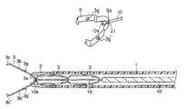
- FIG. 1is a longitudinal side view of a tip end in a ligating apparatus according to a first embodiment of the present invention.
- FIG. 2is a longitudinal side view of a projecting state of a clip in the first embodiment.
- FIG. 3is a longitudinal side view showing that a living tissue is held with a clip in the first embodiment.
- FIG. 4is a side view showing that the clip is fastened in the living tissue according to the first embodiment.
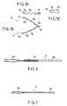
- FIG. 5Ais a plan view showing the clip in the first embodiment.
- FIG. 5Bis a side view showing the clip in the first embodiment.
- FIG. 5Cis a view seen from an arrow A direction of FIG. 5B .
- FIG. 6is a side view of a manipulating wire according to the first embodiment.
- FIG. 7is a side view of the manipulating wire according to a second embodiment of the present invention.
- FIGS. 8A to 8Jare explanatory views of a manufacturing method of the manipulating wire according to the second embodiment.
- FIG. 9Ais a plan view of the clip and manipulating wire according to a third embodiment of the present invention.
- FIG. 9Bis a side view of the clip and manipulating wire according to the third embodiment.
- FIG. 10is a longitudinal side view of the tip end in the ligating apparatus according to a fourth embodiment of the present invention.
- FIG. 11Ais a side view of the clip according to a fifth embodiment of the present invention.
- FIG. 11Bis a perspective view of the clip according to the fifth embodiment.
- FIG. 12Ais a longitudinal side view of a clip apparatus according to a sixth embodiment of the present invention.
- FIG. 12Bis a view seen from an arrow B direction of FIG. 12A .
- FIG. 12Cis a view seen from an arrow C direction of FIG. 12A .
- FIG. 13is a longitudinal side view showing that the clip of the sixth embodiment is fastened in the living tissue.
- FIG. 14is a perspective view of a clip tightening ring according to the sixth embodiment.
- FIG. 15is a longitudinal side view of the clip apparatus according to a seventh embodiment of the present invention.
- FIG. 16is a longitudinal side view of the clip apparatus according to an eighth embodiment of the present invention.
- FIG. 17is a side view of the manipulating wire according to the eighth embodiment.
- FIGS. 18A to 18Dare longitudinal side views showing an action of the clip apparatus according to a ninth embodiment of the present invention.
- FIGS. 19A to 19Care longitudinal side views showing the action of the clip apparatus according to a tenth embodiment of the present invention.
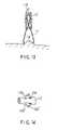
- FIGS. 20A to 20Dare longitudinal side views showing the action of the clip apparatus according to an eleventh embodiment of the present invention, and FIG. 20D is a perspective view of the tip end of an endoscope.
- FIGS. 21A to 21Dare longitudinal side views showing the action of the clip apparatus according to a twelfth embodiment of the present invention.
- FIGS. 22A to 22Care longitudinal side views showing the action of the clip apparatus according to a thirteenth embodiment of the present invention.
- FIGS. 23A to 23Dare front views of modification examples of a hole formed in a base end of the clip according to a fourteenth embodiment of the present invention.
- FIG. 24Ais a side view showing a bulged portion of a fifteenth embodiment of the present invention.
- FIG. 24Bis a front view of the bulged portion.
- FIG. 25Ais a side view showing a different example of the bulged portion.
- FIG. 25Bis a front view of the bulged portion.
- FIG. 26Ais a side view showing another example of the bulged portion.
- FIG. 26Bis a front view of the bulged portion.
- FIG. 27Ais a side view showing another example of the bulged portion.
- FIG. 27Bis a front view of the bulged portion.
- FIG. 28Ais a side view showing another example of the bulged portion.
- FIG. 28Bis a front view of the bulged portion.
- FIGS. 1 to 6show a first embodiment
- FIGS. 1 to 3are longitudinal side views of a tip end in a ligating apparatus.
- An introducing tube 1has flexibility such that the tube can be inserted in a channel of an endoscope, and a tip-end chip 2 is disposed in the tip end of the introducing tube 1 .
- the tip-end chip 2is welded, bonded, or pressed, and fixed to the tip end of the introducing tube 1 .
- a manipulating wire 4is inserted in the introducing tube 1 in such a manner that the wire can freely advance or retreat, and a clip 3 is disconnectably connected to the tip end of the manipulating wire 4 so that the clip can freely project or retract with respect to the tip end of the introducing tube 1 .
- the introducing tube 1is a coil sheath whose inner and outer surfaces with a metal wire (such as stainless steel) having a circular section closely wound therearound have concaves/convexes.
- the introducing tube 1may be a coil sheath which is constituted, for example, by crushing a metal wire (such as stainless steel) having a circular section, setting the wire section to be rectangular, and closely winding the wire around the smooth inner and outer surfaces.
- a metal wiresuch as stainless steel
- the clip 3can easily be projected and the manipulating wire 4 can easily be inserted.
- a coil sheath having a large inner diametercan be realized. Therefore, the projecting of the clip 3 and the inserting of the manipulating wire 4 are further facilitated.
- examples of the introducing tube 1may include a tube sheath of a polymer resin (synthesized polymer polyamide, high/low density polyethylene, polyester, polytetrafluoroethylene, tetrafluoroethylene-perfluoroalkylivinylether copolymer, tetrafluoroethylene-hexafluoropropylene copolymer, and the like).
- a polymer resinsynthetic polymer polyamide, high/low density polyethylene, polyester, polytetrafluoroethylene, tetrafluoroethylene-perfluoroalkylivinylether copolymer, tetrafluoroethylene-hexafluoropropylene copolymer, and the like.
- the introducing tube 1may be a tube sheath formed by disposing and embedding a reinforcing member in a double tube whose wall has inner and outer layers.
- the inner and outer layersare formed of the polymer resin.
- the reinforcing memberis made of a cylindrical blade formed, for example, by knitting a fine metal wire in a lattice form. Therefore, as compared with the tube sheath in which the reinforcing member is not embedded, even when the force for compressing the sheath is applied to the tip end and base end of the sheath, the sheath is superior in resistance to compression and does not buckle.
- the introducing tube 1has an outer diameter of such a dimension that the tube can be inserted through the endoscope channel.
- the thickness of the sheathis determined by rigidity of the material.
- the metal sheathhas a thickness of about 0.2 to 0.7 mm, and the polymer resin tube has a thickness of about 0.3 to 0.8 mm.
- the thicknesscan be reduced, and the sheath inner diameter can advantageously be increased.
- the tip-end chip 2is a short tube of a metal (such as stainless steel), and has an outer peripheral surface tapered toward the tip end. This facilitates the inserting of the introducing tube 1 in the endoscope channel. Moreover, the chip also has a tapered inner peripheral surface, and the clip 3 easily projects from the tip-end chip 2 . Moreover, the inner diameter of the tip end of the tip-end chip 2 is set to such a dimension that a protrusion disposed in the arm portion of the clip 3 fits in the tip end as described later and the arm portion of the clip 3 can be opened.
- the tip end of the tip-end chip 2has an outer diameter of 1.5 to 3.3 mm, and an inner diameter of about 1.0 to 2.2 mm.
- a middle portion of a metal thin stripis bent, a bent portion is formed as a base end 3 a , and opposite arm portions 3 b , 3 b ′ extending from the base end 3 a are bent in an extending/opening direction.
- tip-end edges of the arm portions 3 b , 3 b ′are bent and disposed opposite to each other, and formed as holding portions 3 c , 3 c ′.
- the tip end of one of the holding portions 3 c , 3 c ′is formed in a convex shape 3 d
- the other tip endis formed in a concave shape 3 e , so that a living tissue 5 (see FIG.
- a hook 3 f projecting backwardsis attached to the base end 3 a .
- the hook 3 fis formed by bending the stainless steel strip extending from the base end 3 a substantially in a J shape.
- the respective arm portions 3 b , 3 b ′have projections 3 g , 3 g ′ which can be joined to the tip-end chip 2 during ligating with the clip 3 (when the clip base end is pulled into the tip-end chip).
- the clip 3when the thin strip material of the clip 3 is stainless steel having a spring property, the clip has a rigidity and can securely hold the living tissue.
- the strip of the clip 3has a thickness of 0.15 to 0.3 mm
- the holding portions 3 c , 3 c ′have a strip width of 0.5 to 1.2 mm.
- the arm portions 3 b , 3 b ′have a strip width of 0.5 to 1.5 mm.
- the projections 3 g , 3 g ′have a size of 0.2 to 0.5 mm.
- the base end 3 ahas a strip width of 0.3 to 0.5 mm.
- the hook 3 fprojects from the base end 3 a of the clip 3 by a length of about 1 to 3 mm.
- the manipulating wire 4is constituted of a loop wire 4 a , and a base end wire 4 b .
- the closed loop wire 4 ais molded in the tip end of the base end wire 4 b constituted of metal twined wires.
- the loop wire 4 ais formed by one of the twined wires of the base end wire 4 b .
- the core wiremay be a twined wire or a single wire.
- the loop wire 4 ais welded or bonded to the base end wire 4 b via a metal connection pipe 4 c .
- the loop wire 4 ais attached to the hook 3 f disposed in the base end 3 a of the clip 3 , and disposed in the introducing tube 1 .
- the manipulating wire 4is, for example, a twined wire of stainless steel.
- the twined wirehas a flexibility comparable with the single wire. Therefore, the flexibility of the introducing tube 1 is not degraded.
- a force of 1 to 5 kgis applied to the loop wire 4 a during ligating with the clip 3 .
- the dimension of the loop wire 4 aneeds to be set such that the wire is not ruptured.
- the base end wire 4 bhas an outer diameter of 0.3 to 0.6 mm, and the loop wire 4 a has an outer diameter of 0.2 mm or more.
- the introducing tube 1 of the clip apparatusis introduced into a body cavity via the channel of the endoscope inserted in the body cavity.
- the tip end of the introducing tube 1is positioned in the vicinity of the target tissue to be clipped 5 such as a stomach mucous membrane.
- the manipulating wire 4is pushed toward the tip end of the introducing tube 1 , the clip 3 is projected from the tip end of the tip-end chip 2 . Since the extending/opening property is imparted to the arm portions 3 b , 3 b ′ so as to open the holding portions 3 c , 3 c ′, the clip 3 is projected from the tip-end chip 2 .
- the extending/opening propertyis imparted to the arm portions 3 b , 3 b ′ so as to open the holding portions 3 c , 3 c ′, the clip 3 is projected from the tip-end chip 2 .
- FIG. 1the extending/opening property is imparted to the arm portions 3 b , 3 b ′
- the holding portions 3 c , 3 c ′are opened. Furthermore, when the holding portions 3 c , 3 c ′ are pressed onto the target tissue 5 , and the manipulating wire 4 is drawn, the base end 3 a of the clip 3 is pulled into the tip-end chip 2 , and the projections 3 g , 3 g ′ disposed in the arm portions 3 b , 3 b ′ of the clip 3 engage with the tip end of the tip-end chip 2 . When the manipulating wire 4 is further drawn, the base end 3 a of the clip 3 is plastically deformed. When the holding portions 3 c , 3 c ′ are closed, the target tissue 5 can be held as shown in FIG. 3 .
- the manipulating wire 4is further drawn, and a traction force is applied to the hook 3 f attached to the base end 3 a of the clip 3 .
- the hook 3 f bent in the J shapeis stretched, the loop wire 4 a is detached from the hook 3 f , and the manipulating wire 4 is completely detached from the clip 3 .
- the clip 3is completely fastened into the target tissue 5 .
- the holding portions 3 c , 3 c ′ of the clip 3hold the tissue, the target tissue 5 cannot securely be grasped in some case.
- a tissue different from the targeted tissueis grasped by the clip 3 in other case.
- the clip 3 having the holding portions 3 c , 3 c ′ once closedis again extended/opened, the tissue is again targeted, and the clip 3 is again closed.
- the manipulating wire 4is slightly drawn from the state shown in FIG. 2 . While the tissue is held between the holding portions 3 c , 3 c ′ of the clip 3 , and the clip 3 needs to be extended/opened again, the opening of the clip is realized by the following action. That is, the manipulating wire 4 is pushed forwards, or pulled toward the base end of the introducing tube 1 , so that the arm portions 3 b , 3 b ′ of the clip 3 are extended/opened. In this case, the base end 3 a of the clip 3 is not plastically deformed yet. Therefore, the arm portions 3 b , 3 b ′ of the clip 3 can be extended/opened by an elastic force given beforehand. In this case, the target tissue 5 can be targeted and grasped by the clip 3 again.
- the number of componentsdecreases in an engaging portion of the clip and manipulating wire. This can reduce a manufacturing cost. Moreover, the attachment manipulating of the clip during manufacturing is facilitated. Furthermore, after a first clip is fastened in the living tissue, the clip apparatus is extracted from the endoscope channel. When a second clip is attached again, the loop wire is simply attached to the hook of the clip. The clip attachment manipulating is therefore facilitated.
- FIGS. 7 and 8A to 8 Jshow a second embodiment.
- FIG. 7is a side view of the tip end of the manipulating wire
- FIGS. 8A to 8Jshow a manufacturing method of the manipulating wire.
- the wire having the closed loop portion in the tip end as described in the first embodimentis known in Jpn. Pat. Appln. KOKAI Publication No. 2000-271146.
- the loop wire forming a closed loopis joined to the tip end of the manipulating wire via a joint pipe.
- the joint pipe for joining the manipulating wire to the loop wireis surely required.
- the core wire of the twined manipulating wireis used as the loop wire and the closed loop is formed.
- the joint pipeis required for joining the loop wire to the manipulating wire.
- the outer diameter of the joint portion of the loop wire and manipulating wireincreases.
- the clearance from the inner surface of the introducing tube (insertion portion) constituting a treatment tool for the endoscopedecreases, and contact resistance also increases.
- the inner diameter of the introducing tube as the treatment tool for the endoscopeis of the order of 1 to 2.5 mm and very small. There is a problem that even a slight increase in the outer diameter remarkably degrades the insertion property.
- a manipulating wire 5is constituted of a loop wire 5 a and base end wire 5 b .
- the base end wire 5 bis constituted of a twined wire of a metal, and constituted, for example, by twining three material wires.
- the outer diameter of the wireis about 0.3 mm to 0.6 mm in diameter.
- a wire end portion 8 cis loosened as shown in FIG. 8A .
- wire Ais loosened while it is turned, as shown in FIG. 8B . At this time, a length of about 60 mm is loosened from the wire end portion 7 c similarly.
- Second wire B or Cis loosened similarly as shown in FIG. 8C . At this time, a length of about 60 mm is loosened from the wire end portion 7 c similarly.
- Second wire B or Cis folded as shown in FIG. 8D .
- a folded end X and a loosened end Ymust be spaced sufficiently from each other.
- the folded wire Bis turned and twisted in the loosing direction, as shown in FIG. 8E (in the case of Z twisting). At this time, a deformed end portion is cut in advance before twisted. As shown in FIG. 8F , the twist-back length is about 30 mm.
- wire Cis twisted back to wire B, and the wire is cut at a location of the folded end of wire B. At this time, wires C and B are provided so as not to be spaced and superimposed. (This is because wire A easily slips when it is returned).
- wire Ais twisted back to wires B and C. At this time, it is desirable that an abutment portion between wire C and wire B be observed under a substance microscope. In addition, care must be taken so that wire C and wire B do not move when a portion forward or backward of the abutment portion is twisted.
- wire Awhen wire A is loaded, care must be taken so as not to flip wires B and C in a direction indicated by the filled arrow. Wire A is easily loaded by placing the wire at a distal end side (loop side) relevant to the abutment portion of wires B and C.
- the loopis defined as about 5 mm in length.
- the abutment portion of wires B and C and the end portion of wire Amay be prevented from looseness of twist by means of welding, adhesive, or any other method.
- the connection pipe 4 csince the connection pipe 4 c is not disposed, the number of components decreases, accordingly the number of assembly steps by the joining manipulating such as welding, bonding, and caulking can also be decreased, and therefore, the manufacturing cost can be reduced.
- the outer diameteris not enlarged even in the joint portion of the base end wire 5 and loop wire 5 a , friction resistance with the inner surface of the introducing tube 1 does not increase, and the insertion property of the manipulating wire 5 is kept. Thereby, the clip 3 can easily be projected from the introducing tube 1 .
- the hard portionis not formed in the joint portion of the loop wire and manipulating wire, the flexibility can be maintained, and the insertion property of the endoscope into the forceps channel can be held.
- FIGS. 9A , 9 Bshow a third embodiment, the same constituting portions as those of the first embodiment are denoted with the same reference numerals, and the description thereof is omitted.
- FIG. 9Ais a plan view of the clip and manipulating wire
- FIG. 9Bis a side view.
- a manipulating wire 6is formed by bending the tip end of the wire in a flat loop shape and joining the tip end to the hook 3 f of the clip 3 , and two manipulating wires 6 are inserted into the base end of the introducing tube 1 .
- the manipulating wire 6may be coated with a polymer resin 6 a having excellent slippage, such as high/low density polyethylene, and polytetrafluoroethylene.
- the thickness of the coatingis optimum in a range of about 0.05 mm to 0.1 mm.
- the wire surfaceis subjected to embossment of 0.01 mm to 0.45 mm, or may effectively be coated with a silicone oil.
- the manipulating wire 6is a twined or single wire of a metal such as stainless steel, and has an outer diameter of about 0.2 to 0.5 mm.
- the action of the third embodimentincludes: drawing two manipulating wires 6 altogether. Other actions are the same as those of the first embodiment, and the description thereof is omitted.
- the clipcan be joined to the manipulating wire with a simpler constitution. Since the wire is coated with the polymer resin 6 a , the slippage of the manipulating wire is enhanced, the friction resistance with the inner surface of the introducing tube decreases, and the traction force amount can be transmitted to the tip end of the introducing tube without any loss, so that the ligating manipulating can be performed with a smaller force.
- FIG. 10shows a fourth embodiment, the same constituting portions as those of the first embodiment are denoted with the same reference numerals, and the description thereof is omitted.
- a clip 8 of the fourth embodimentis constituted by omitting the hook 3 f of the clip 3 of the first embodiment, bending the clip substantially in a U shape, and joining the loop wire 4 a directly to a base end 8 a of the clip 8 .
- the diameter of the loop wire 4 ais set to about 0.1 to 0.2 mm.
- the manipulating wire 4is drawn.
- the arm portions 3 b , 3 b ′ of the clip 8 bent in the extending/opening directionengage with the tip end of the tip-end chip 2 .
- the arm portions 3 b , 3 b ′ of the clip 8are pulled in the tip-end chip 2 , the holding portions 3 c , 3 c ′ are closed, and the target tissue 5 can be held.
- the loop wire 4 ais ruptured. A force of 1 to 5 kg is applied to the loop wire 4 a during ligating with the clip 8 .
- the dimensionis set such that the loop wire 4 a is ruptured with the application of the force.
- the clip 8When the loop wire 4 a is ruptured, the clip 8 is disengaged from the manipulating wire 4 , and the clip 3 can be fastened in the living tissue.
- the twined-back length of the wire Bis set to be short, and the loop is untwined during ligating, so that the clip 8 may be disengaged from the manipulating wire 4 .
- An appropriate twined-back lengthis in a range of about 5 to 10 mm.
- the clipcan be molded more inexpensively.
- FIGS. 11A , 11 Bshow a fifth embodiment, the same constituting portions as those of the first embodiment are denoted with the same reference numerals, and the description thereof is omitted.
- a clip 9is constituted by omitting the hook 3 f of the clip 3 of the first embodiment, bending the clip substantially in the U shape, and forming a hole 21 for passing a manipulating wire 10 in a base end 9 a of the clip 9 .
- the manipulating wire 10is a metal single wire, and has a diameter of about 0.2 to 0.7 mm.
- the manipulating wire 10is inserted through the hole 21 , and a flat bulged portion 10 a as a stopper is disposed in the tip end of the manipulating wire 10 .
- Examples of a method for molding the flat bulged portion 10 ainclude caulking, laser, and plasma welding.
- An appropriate diameter of the hole 21is in a range of about 0.2 to 0.7 mm.
- the manipulating wire 10 which can be inserted through the hole 21is used.
- the maximum diameter of the flat bulged portion 10 ais necessarily larger than the diameter of the hole 21 , and is in a range of about 0.25 to 1 mm.
- the manipulating wire 10is drawn.
- the arm portions 3 b , 3 b ′ of the clip 9 bent in the extending/opening directionengage with the tip end of the tip-end chip 2 .
- the arm portions 3 b , 3 b ′ of the clip 9are pulled in the tip-end chip 2 , the holding portions 3 c , 3 c ′ are closed, and the target tissue 5 can thereby be held.
- the flat bulged portion 10 a on the tip end of the manipulating wire 10is extracted from the hole 21 of the clip base end 3 a .
- the diameter of the flat bulged portion 10 ais deformed and reduced, or the hole 21 of the base end 3 a of the clip 9 is deformed and enlarged, so that the manipulating wire 10 is disengaged from the clip 9 .
- the clip 9can be fastened in the living tissue.
- the clipis directly joined to the manipulating wire, and the number of components in the engaging portion of the clip and manipulating wire decreases. Thereby, the manufacturing cost is reduced. Moreover, the attachment manipulating of the clip during manufacturing is facilitated.
- FIGS. 12A , 12 B, 12 C to 14show a sixth embodiment, the same constituting portions as those of the first embodiment are denoted with the same reference numerals, and the description thereof is omitted.
- the tip-end chip 2is welded, bonded, or pressed into the tip end of the introducing tube 1 .
- the tip-end chip 2is a short tube of a metal (such as stainless steel), and has an outer peripheral surface tapered toward the tip end. Therefore, the inserting of the introducing tube 1 into the endoscope channel can be facilitated.
- the inner peripheral surface of the tip-end chip 2is also tapered, and the inner diameter of the tip end is substantially the same in dimension as the outer diameter of a clip tightening ring described later. This suppresses looseness of the clip tightening ring.
- the outer diameter of the tip edge of the tip-end chip 2is in a range of 1.5 to 3.3 mm, and the inner diameter of the tip edge of the tip-end chip 2 is in a range of about 1.0 to 2.2 mm.
- a clip 11is formed by bending a thin metal strip at a middle portion, forming the curved portion as a base end 11 a , and allowing opposite arm portions 11 b , 11 b ′ extending from the base end 11 a to intersect each other. Furthermore, the tip edges of the respective arm portions 11 b , 11 b ′ are bent so that the tip edges are disposed opposite to each other as holding portions 11 c , 11 c ′. For the tip ends of the holding portions 11 c , 11 c ′, one end is formed in a convex shape 11 d , and the other end is formed in a concave shape 11 e , so that the living tissue is easily grasped.
- the extending/opening propertyis imparted to the arm portions 11 b , 11 b ′ so as to open the holding portions 11 c , 11 c ′.
- a hook 11 f projecting rearwardsis attached to the base end 11 a .
- the hook 11 fis formed by molding the strip beforehand in a J shape, and bending the strip at the base end 11 a.
- Examples of the material of the thin strip constituting the clip 11include stainless steel which has the spring property, and rigidity and which can securely grasp the living tissue.
- the examplesalso include a super-elastic alloy such as a nickel-titanium alloy. When the extending/opening property is imparted to the arm portions, the arm portions of the clip projecting from the sheath open more securely.
- the thickness of the strip of the clip 11is in a range of 0.15 to 0.3 mm.
- the holding portionhas a strip width of 0.5 to 1.2 mm.
- the arm portionhas a strip width of 0.5 to 1.5 mm.
- the base endhas a strip width of 0.3 to 0.5 mm.
- the hookprojects from the clip base end by a length of about 1 to 3 mm.
- a clip tightening ring 12 disposed in the base end of the clip 11is molded of a resin, metal, or the like which has strength and elasticity. Additionally, a pair of blades 12 a , 12 a ′ are disposed in a ring outer peripheral portion such that the blades are elastically deformed and can freely project or retract in a circumferential direction.
- the number of blades 12 a , 12 a ′is not limited to two, and three or four blades may be used.
- the arm portions 11 b , 11 b ′ of the clip 11When the clip tightening ring 12 is attached to the arm portions 11 b , 11 b ′ of the clip 11 , the arm portions 11 b , 11 b ′ of the clip are closed.
- the ringhas a substantially tubular shape.
- the clip 11is joined to the manipulating wire 4 by attaching the loop wire 4 a to the hook 11 f . Additionally, even when the clip 11 is pushed out by the manipulating wire 4 , the engaging of the clip 11 and manipulating wire 4 is held, and the clip 11 and clip tightening ring 12 can tentatively be fixed. In this manner, a polymer material such as silicone 13 is fitted in the clip tightening ring 12 .
- the blades 12 a , 12 a ′ of the clip tightening ring 12may be disposed in the introducing tube 1 in the folded state. However, when the blades 12 a , 12 a ′ are disposed in projecting states, the elasticity of the blades 12 a , 12 a ′ can be maintained over a long period. Moreover, since the contact resistance between the inner surface of the introducing tube 1 and the blades decreases, the force amount for moving the clip 11 in the introducing tube 1 can also be decreased.
- the clip tightening ring 12is molded by injecting resins having strength and elasticity (polybutylterephthalate, polyamide, polyphenyl amide, liquid crystal polymer, polyether ketone, polyphthal amide).
- resins having strength and elasticitypolybutylterephthalate, polyamide, polyphenyl amide, liquid crystal polymer, polyether ketone, polyphthal amide.
- the ringis molded by injecting, cutting, or plasticizing metals having elasticity (super-elastic alloy such as stainless steel, and nickel-titanium alloy).
- the tubular portion of the clip tightening ring 12has an inner diameter of 0.6 to 1.3 mm, and outer diameter of about 1.0 to 2.1 mm.
- the diameter of an outermost diametric portionis set to 1 mm or more in consideration with the engaging with the tip-end chip 2 .
- the tip end of the introducing tube 1is guided to a target site.
- the clip 11 and clip tightening ring 12 disposed in the introducing tube 1are projected from the tip-end chip 2 . This is realized by pushing the manipulating wire 4 toward the tip end of the introducing tube 1 .
- the blades 12 a , 12 a ′ of the clip tightening ring 12are folded when passed through the tip-end chip 2 . However, the blades 12 a , 12 a ′ are passed through the tip-end chip 2 , and again projected. Thereby, the clip tightening ring 12 is prevented from entering the tip-end chip 2 again.
- the clip 11is guided to hold a target living tissue 14 .
- the manipulating wire 4is further drawn, the arm portions 11 b , 11 b ′ of the clip 11 are pulled into the clip tightening ring 12 , and the holding portions 11 c , 11 c ′ of the clip 11 are closed.
- the living tissue 14is securely held by the arm portions 11 b , 11 b ′ of the clip, the manipulating wire 4 is further drawn, and the hook 11 f is stretched, the engaging of the clip 11 and manipulating wire 4 is released. Thereby, the clip 11 which holds the living tissue 14 can be fastened in the body cavity.
- the clip tightening ringconfines the arm portions of the clip, the living tissue can be ligated with a stronger force.
- FIG. 15shows a seventh embodiment, the same constituting portions as those of the first embodiment are denoted with the same reference numerals, and the description thereof is omitted.
- a manipulating member 15 having flexibilityis inserted in the introducing tube 1 so that the member can advance or retreat.
- the manipulating member 15is disposed behind a clip tightening ring 16 disposed in the introducing tube 1 as described later, and directly receives the force applied by the manipulating wire 4 during ligating with the clip 11 .
- the manipulating member 15is a coil sheath which is constituted, for example, by closely winding a metal wire having a circular section (such as stainless steel) around the inner and outer surfaces having concaves/convexes.
- a metal wire having a circular sectionsuch as stainless steel
- the manipulating member 15may be a square coil sheath which is constituted, for example, by crushing a metal wire (such as stainless steel) having a circular section, setting the wire section to be rectangular, and closely winding the wire around the smooth inner and outer surfaces. Moreover, as compared with the round coil sheath, even when the same diameter of the material wire is used, the coil sheath having a large inner diameter can be realized. Therefore, the projecting of the clip and the inserting of the manipulating wire are further facilitated.
- a metal wiresuch as stainless steel
- the manipulating member 15may be a tube sheath of a polymer resin (synthesized polymer polyamide, high/low density polyethylene, polyester, polytetrafluoroethylene, tetrafluoroethylene-perfluoroalkylivinylether copolymer, tetrafluoroethylene-hexafluoropropylene copolymer, and the like). Since the inner and outer surfaces of the sheath have smoothness, the inserting of the sheath in the introducing tube 1 , and the inserting of the manipulating wire 4 are facilitated.
- a polymer resinsynthetic polymer polyamide, high/low density polyethylene, polyester, polytetrafluoroethylene, tetrafluoroethylene-perfluoroalkylivinylether copolymer, tetrafluoroethylene-hexafluoropropylene copolymer, and the like. Since the inner and outer surfaces of the sheath have smoothness, the inserting of the sheath in the
- the manipulating member 15may be a tube sheath formed by disposing and embedding a reinforcing member in a double tube whose wall has inner and outer layers.
- the inner and outer layersare formed of the polymer resin.
- the reinforcing memberis made of a cylindrical blade formed, for example, by knitting a fine metal wire in a lattice form. Therefore, as compared with the tube sheath in which the reinforcing member is not embedded, even when the force for compressing the sheath is applied to the tip end and base end of the sheath, the sheath is superior in resistance to compression and does not buckle.
- the manipulating member 15has an outer diameter which can be passed in the introducing tube 1 , an inner diameter through which the manipulating wire 4 can be inserted, and an outer diameter of 3 mm or less.
- the inner diameteris set as large as possible. Additionally, a projecting force amount can securely be transmitted.
- the thickness of the memberneeds to be set such that the member does not buckle even under the force applied during ligating with the clip 11 .
- the clip tightening ring 16is attached to the arm portions 11 b , 11 b ′ of the clip 11 , the arm portions 11 b , 11 b ′ of the clip 11 are closed, and the ring has a substantially tubular form.
- the clip 11is joined to the manipulating wire 4 by attaching the loop wire 4 a to the hook 11 f.
- the clip tightening ring 16is molded by injecting resins having strength (polybutylterephthalate, polyamide, polyphenyl amide, liquid crystal polymer, polyether ketone, polyphthal amide).
- resins having strengthpolybutylterephthalate, polyamide, polyphenyl amide, liquid crystal polymer, polyether ketone, polyphthal amide.
- the ringmay be molded by injecting, cutting, or is plasticizing the metal (such as stainless steel).
- the clip tightening ring 16has an inner diameter of 0.6 to 1.3 mm, and outer diameter of about 1.0 to 2.1 mm.
- the tip end of the introducing tube 1is guided to the living tissue 14 .
- the clip 11 and clip tightening ring 16 disposed in the introducing tube 1are projected from the introducing tube 1 . This is realized by pushing the manipulating member 15 toward the tip end of the introducing tube 1 , or by drawing the introducing tube 1 toward the base end.
- the clip 11is guided to hold the target living tissue 14 .
- the manipulating wire 4is further drawn, the arm portions 11 b , 11 b ′ of the clip 11 are pulled into the clip tightening ring 16 , and the holding portions 11 c , 11 c ′ of the clip 11 are closed.
- the living tissue 14is securely held by the arm portions 11 b , 11 b ′ of the clip, the manipulating wire 4 is further drawn, and the hook 11 f is stretched, the engaging of the clip 11 and manipulating wire 4 is released. Thereby, the clip 11 which holds the living tissue 14 can be fastened in the body cavity.
- a manipulating for projecting the clip from the introducing tubecan more easily and securely be performed.
- FIGS. 16 and 17show an eighth embodiment.
- the eighth embodimentis different from the seventh embodiment in a clip 17 and manipulating wire 18 .
- the hook 11 f of the clip 11 described in the seventh embodimentis omitted.
- the other constitutionis the same as that of the clip 11 .
- the manipulating wire 18is formed of a single or twined metal wire, and has a bent tip end to form a loop portion 18 a .
- An outer diameteris of the order of 0.1 to 0.6 mm.
- the loop portion 18 a of the manipulating wire 18is directly joined to a base end 17 a of the clip 17 .
- the clip 17is guided to hold the target living tissue 14 .
- the manipulating wire 18is further drawn, the arm portions 17 b , 17 b ′ of the clip 17 are pulled into the clip tightening ring 16 , and the holding portions of the clip 17 are closed.
- the living tissue 14is securely held by the holding portions of the clip 17
- the manipulating wire 18is further drawn, and the loop portion 18 a is substantially linearly stretched. This releases the engaging of the clip 17 and manipulating wire 18 .
- the clip 11 with the living tissue 14 held thereincan be fastened in the body cavity.
- the eighth embodimentin addition to the effect of the seventh embodiment, the following effect is produced. Since it is unnecessary to mold the hook 11 f in the base end of the clip 17 , the clip 17 can be manufactured less expensively. Moreover, since the loop portion 18 a of the tip end of the manipulating wire 18 is formed simply by bending the wire, the manipulating wire 18 can be molded less expensively, and can easily be joined to the base end of the clip 17 .
- FIGS. 18A to 18Dshow a ninth embodiment, and are longitudinal side views showing the action of the ligating apparatus.
- the same constituting portions as those of the seventh embodimentare denoted with the same reference numerals, and the description thereof is omitted.
- the manipulating wire 10is passed through the manipulating member 15 such that the wire can advance or retreat.
- the clip 9has the same structure as that of the fifth embodiment shown in FIGS. 11A , 11 B.
- the hole 21 through which the manipulating wire 10 can be insertedis formed in the base end 9 a of the clip 9 .
- the bulged portion 10 a as the stopper larger than the hole 21is disposed in the tip end of the manipulating wire 10 .
- the clip tightening ring 16 formed of a cylindrical pipeis disposed between the tip end surface of the manipulating member 15 and the base end of the clip 9 , while the manipulating wire 10 is inserted through the ring.
- the clip 9is attached to the tip end of the introducing tube 1 , and the manipulating member 15 abuts on the base end 9 a of the clip 9 via the clip tightening ring 16 before ligating.
- the clipis directly joined to the manipulating wire, and the number of components in the engaging portion of the clip and manipulating wire decreases. Thereby, the manufacturing cost is reduced. Moreover, the attachment manipulating of the clip during manufacturing is facilitated.
- the living tissuecan be ligated with a stronger force. Furthermore, since the clip tightening ring confines the arm portions of the clip, the living tissue can be ligated with a much stronger force.
- FIGS. 19A to 19Cshow a tenth embodiment, and are longitudinal side views showing the action of the ligating apparatus.
- the same constituting portions as those of the seventh embodimentare denoted with the same reference numerals, and the description thereof is omitted.
- the manipulating wire 10is passed through the manipulating member 15 such that the wire can advance or retreat.
- the clip 9has the same structure as that of the fifth embodiment shown in FIGS. 11A , 11 B and that of the ninth embodiment.
- the hole 21 through which the manipulating wire 10 can be insertedis formed in the base end 9 a of the clip 9 .
- the bulged portion 10 a as the stopper larger than the hole 21is disposed in the tip end of the manipulating wire 10 .
- the clip tightening ring 12 as engaging meanshaving the same structure as that of the sixth embodiment shown in FIG. 14 is disposed between the tip end surface of the manipulating member 15 and the base end of the clip 9 , while the manipulating wire 10 is inserted through the ring.
- the clip 9is attached to the tip end of the introducing tube 1 , and the manipulating member 15 abuts on the base end 9 a of the clip 9 via the clip tightening ring 12 before ligating.
- the clip tightening ring 12can be prevented from entering the tip-end chip 2 again.
- the force applied by the manipulating wire 10can securely be received by the tip-end chip 2 via the clip tightening ring 12 .
- the living tissuecan be ligated with a stronger force.
- the clip tightening ringconfines the arm portions of the clip, the living tissue can be ligated with a much stronger force.
- FIGS. 20A to 20Dshow an eleventh embodiment, and are longitudinal side views showing the action of the ligating apparatus.
- the same constituting portions as those of the fifth embodimentare denoted with the same reference numerals, and the description thereof is omitted.
- the manipulating wireis constituted by the bulged portion 11 a and base end wire 10 ′.
- the base end wire 10 ′is welded or bonded to the manipulating wire 10 .
- the core wire of the base end wire 10 ′ constituted of the metal twined wireis used in the manipulating wire 10 , only one wire is used, the number of components decreases, and therefore the manufacturing cost can be reduced.
- the diameter of the base end wire 10 ′is of the order of 0.3 to 1.5 mm.
- the clip 3basically has the same structure as that of the first embodiment shown in FIGS. 1 to 5A , 5 B, 5 C. Similarly as the ninth embodiment, the hole 21 is formed in the base end 3 a . A plurality of clips 3 are disposed in series in the introducing tube 1 , the manipulating wire 10 is inserted through the hole 21 of each clip 3 , the bulged portion a is fit in the hole 21 of a front end, and the manipulating wire 10 is prevented from dropping.
- the plurality of clips 3are disposed in series in the tip end of the introducing tube 1 , and the bulged portion 10 a is fit in the hole 21 of the front clip 3 .
- the front clip 3projects from the tip end of the introducing tube 1 , and the arm portions 3 b , 3 b ′ largely extend/open.
- the base end wire 10 ′is drawn, the base end 3 a of the clip 3 is pulsed into the tip-end chip 2 , and the projections 3 g , 3 g ′ disposed in the arm portions 3 b , 3 b ′ of the clip 3 engage with the tip end of the tip-end chip 2 as shown in FIG. 20C .
- the base end wire 10 ′is further drawn, the base end 3 a of the clip 3 is plastically deformed, the holding portions 3 c , 3 c ′ are closed, and the target tissue 14 can be held.
- the bulged portion 10 a of the tip end of the manipulating wire 10deforms and enlarges the hole 21 of the base end 3 a of the clip 3 . Thereby, the manipulating wire 10 is separated from the clip 3 , and the clip 3 can be fastened in the living tissue.
- the bulged portion 10 a of the manipulating wire 10engages in the hole 21 of the second clip 3 , and the second clip 3 can be projected from the tip-end chip 2 on the tip end of the introducing tube 1 .
- the living tissuecan continuously be ligated with the clip 3 .
- the engaging structure of the clip and manipulating wireis simplified, and the number of components can be decreased, so that the manufacturing cost can be reduced. Moreover, the attachment manipulating of the clip during manufacturing can be facilitated, and a dispersion in assembly can be prevented. Furthermore, since the clip in the introducing tube is positioned in the vicinity of a center by the manipulating wire, the clip projects by a small force amount. Moreover, the ligating of the tissue with the clip can be continuously performed simply by drawing one base end wire, and operability can therefore be enhanced.
- the holding portions 3 c , 3 c ′ of the clip 3hold the tissue, the target tissue 14 cannot securely be held in some case.
- the tissue different from the targeted tissueis grasped by the clip 3 in some case.
- the clip 3 having the holding portions 3 c , 3 c ′ once closedis extended/opened again, the tissue is targeted again, and the clip 3 is sometimes closed again.
- the base end wire 10 ′is slightly drawn from the state shown in FIG. 20B . While the tissue is held between the holding portions 3 c , 3 c ′ of the clip 3 , and the clip 3 needs to be extended/opened again, the opening of the clip is realized by the following action. That is, the base end wire 10 ′ is pushed forwards, or pulled toward the base end of the introducing tube 1 , so that the arm portions 3 b , 3 b ′ of the clip 3 are extended/opened. In this case, the base end 3 a of the clip 3 is not plastically deformed yet. Therefore, the arm portions 3 b , 3 b ′ of the clip 3 can be extended/opened by the elastic force given beforehand. In this case, the target tissue 14 can be targeted and grasped by the clip 3 again.
- the treatment tool for the endoscopeusually has a total length of 1000 mm or more and is very long. Therefore, it is difficult to package the tool in a straightened state, and the introducing tube 1 is packaged in a small rolled state. To set a package case to be smaller, it is general to roll and package the introducing tube 1 to be as small as possible.
- the ligating apparatusin which the plurality of clips 3 are disposed as described above, when the introducing tube 1 is largely bent during packaging, the clip 3 disposed in the introducing tube 1 is possibly deformed and broken, and possibly the clip cannot sufficiently fulfill the function.
- a minimum bend radius r of a curved portion 32 of the tip end of an endoscope 31is about 15 mm. Therefore, the clip 3 has to be designed not to be deformed or broken, even when the introducing tube 1 of the ligating apparatus is bent to the bend radius r of 15 mm at minimum. Thereby, in the ligating apparatus in which the plurality of clips 3 are disposed, the introducing tube 1 with the clips 3 disposed therein needs to be packaged at the bend radius r of 15 mm or more, or in the straightened state.
- the introducing tube 1 of the ligating apparatusis inserted in the forceps channel of the endoscope 31 , and the introducing tube 1 including the clips 3 is disposed behind the curved portion 32 of the endoscope 31 , it is very difficult to project the clips 3 from the introducing tube 1 .
- the curved portion 32 of the endoscope 31forms a large resistance, and the clip 3 disposed in the base end of the introducing tube 1 cannot be moved in a tip end direction of the introducing tube 1 .
- the introducing tube 1 including the clip 3has to be disposed before the curved portion 32 of the endoscope 31 .
- the length of the curved portion 32 of the endoscope 31is about 120 mm from the tip end of the endoscope.
- the introducing tube 1 inserted in the forceps channel of the endoscope 31needs to be projected to a position in a view field of the endoscope 31 from the tip end of the endoscope.
- the length to the tip end of the introducing tube from the tip end of the endoscopeis called a minimum visible distance L.
- the minimum visible distance L of the endoscope 31is about 5 mm. Therefore, the introducing tube 1 including the clips 3 is not disposed in the curved portion 32 of the endoscope 31 in a position projecting from the tip end of the endoscope by at least 5 mm. Thereby, all the clips 3 need to be disposed in a position of 125 mm or less from the tip end of the introducing tube 1 of the ligating apparatus.
- FIGS. 21A to 21Dshow a twelfth embodiment, and are longitudinal side views showing the action of the ligating apparatus.
- the same constituting portions as those of the ninth embodimentare denoted with the same reference numerals, and the description thereof is omitted.
- a plurality of clips 9 and a plurality of clip tightening rings 16are alternately disposed in series in the introducing tube 1 .
- the clip 9 and clip tightening ring 16have the same structure as that of the ninth embodiment shown in FIGS. 18A to 18D , and the hole 21 through which the manipulating wire 10 can be inserted is formed in the base end 9 a of the clip 9 .
- the bulged portion 10 a as the stopper larger than the hole 21is disposed in the tip end of the manipulating wire 10 .
- the clip tightening ring 16 formed of the cylindrical pipe through which the manipulating wire 10 is insertedis disposed between the tip end surface of the manipulating member 15 and the base end of the clip 9 .
- the manipulating wire 10is inserted through the hole 21 of the clip 9 , the bulged portion 10 a is fit in the hole 21 of the front clip 9 , and the manipulating wire 10 is stopped from dropping.
- the plurality of clips 9 and the plurality of clip tightening rings 16are alternately disposed in series in the introducing tube 1 , and the tip end of the manipulating member 15 abuts on the base end of the rearmost clip tightening ring 16 before ligating.
- the manipulating member 15is advanced or the introducing tube 1 is retreated, the bulged portion 10 a of the manipulating wire 10 is engaged in the hole 21 of the second clip 9 , and the second clip 9 can be projected from the tip end of the introducing tube 1 .
- the similar manipulatingis repeated, the living tissue can continuously be ligated with the clip 9 .
- the force applied by the manipulating wirecan be securely received by the manipulating member, and the living tissue can be ligated with a stronger force.
- the clip tightening ringconfines the arm portions of the clip 3 , the living tissue can be ligated with a much stronger force.
- FIGS. 22A to 22Cshow a thirteenth embodiment, and are longitudinal side views showing the action of the ligating apparatus.
- the same constituting portions as those of the tenth embodimentare denoted with the same reference numerals, and the description thereof is omitted.
- the plurality of clips 9 and the plurality of clip tightening rings 12are alternately disposed in series in the introducing tube 1 .
- the clip 9 and clip tightening ring 12have the same structure as that of the tenth embodiment shown in FIGS. 19A to 19C , and the hole 21 through which the manipulating wire 10 can be inserted is formed in the base end 9 a of the clip 9 .
- the bulged portion 10 a as the stopper larger than the hole 21is disposed in the tip end of the manipulating wire 10 .
- the clip tightening ring 12 as engaging meanshaving the same structure as that of the tenth embodiment is disposed between the tip end surface of the manipulating member 15 and the base end of the clip 9 , while the manipulating wire 10 is inserted through the ring.
- the plurality of clips 9 and the plurality of clip tightening rings 12are alternately disposed in series in the introducing tube 1 , and the tip end of the manipulating member 15 abuts on the base end 9 a of the rearmost clip tightening ring 12 before ligating.
- the clip tightening ring 12can be prevented from entering the tip-end chip 2 again.
- the force applied by the manipulating wire 10can securely be received by the tip-end chip 2 via the clip tightening ring 12 .
- the manipulating member 15is advanced or the introducing tube 1 is retreated, the bulged portion 10 a of the manipulating wire 10 engages in the hole 21 of the second clip 9 , and the second clip 9 can be projected from the tip end of the introducing tube 1 .
- the similar manipulatingis repeated, the living tissue can continuously be ligated with the clip 9 .
- the living tissuein addition to the effect of the eleventh embodiment, since the force applied by the manipulating wire can securely be received by the engaging means, the living tissue can be ligated with a stronger force. Moreover, since the clip tightening ring confines the arm portions of the clip, the living tissue can be ligated with a much stronger force.
- FIGS. 23A to 23Dshow a fourteenth embodiment, and modification examples of the hole 21 formed in the base end 3 a , 9 a of the clip 3 , 9 .
- FIG. 23Ashows an elongated slit.
- the elongated slithas a length of about 0.5 to 1.5 mm, and a height of about 0.2 to 0.7 mm.
- FIG. 23Bshows a round hole formed in the middle portion of the elongated slit.
- the elongated slithas a length of about 0.5 to 1.5 mm, and a height of about 0.2 to 0.6 mm, and the diameter of the round hole is of the order of 0.3 to 0.7 mm and is larger than the height of the elongated slit.
- FIG. 23Ashows an elongated slit.
- the elongated slithas a length of about 0.5 to 1.5 mm, and a height of about 0.2 to 0.6 mm, and the diameter of the round
- FIG. 23Cshows a cross-shaped slit.
- the cross-shaped slithas a length of about 0.5 to 1.5 mm, a height of about 0.3 to 0.7 mm, and a width of about 0.15 to 0.4 mm.
- FIG. 23Dshows four pieces projecting toward the middle portion from the inner peripheral portion of the round hole.
- the round holehas a diameter of about 0.4 to 0.7 mm, and the projecting piece has a height of about 0.15 to 0.3 mm.
- FIGS. 24A to 28Bshow a fifteenth embodiment, and modification examples of the bulged portion disposed in the tip end of the manipulating wire 10 .
- FIGS. 24A , 24 Bshow a flat bulged portion 10 b formed by crushing the tip end of the manipulating wire 10 to be flat.
- the flat bulged portion 10 bis necessarily larger than the hole of the clip base end, and has a width of about 0.4 to 1 mm, thickness of about 0.2 to 0.7 mm, and length of about 0.3 to 3 mm.
- FIGS. 25A , 25 Bshow that a pipe-shaped member 10 c is attached to the tip end of the manipulating wire 10 to form the bulged portion.
- the pipe-shaped member 10 cis welded or bonded.
- the diameter of the bulged portionis necessarily larger than that of the hole of the clip base end, and is of the order of 0.25 to 1 mm.
- the bulged portionhas a length of about 0.25 to 3 mm.
- FIGS. 26A , 26 Bshow a bulged portion 10 d formed by caulking and processing the tip end of the manipulating wire 10 in a conical shape.
- the diameter of the bulged portion 10 dis necessarily larger than that of the hole of the clip base end, and is of the order of 0.25 to 1 mm.
- the bulged portion 10 dhas a length of about 0.25 to 3 mm.
- FIGS. 27A , 27 Bshow a bulged portion 10 e formed by heating and processing the tip end of the manipulating wire 10 in a spherical shape.
- the diameter of the bulged portion 10 eis necessarily larger than that of the hole of the clip base end, and is of the order of about 0.25 to 1 mm.
- FIGS. 28A , 28 Bshow a bulged portion 10 f formed by bending back the tip end of the manipulating wire 10 .
- the diameter of the manipulating wireis of the order of 0.15 to 1 mm and is necessarily larger than that of the hole of the clip base end when bent.
- the bent-back length of the bulged portion 10 fis of the order of 0.5 to 3 mm.
- the bulged portioncan easily be formed and the cost can be reduced.
- FIGS. 25A , 25 Bthe dimension of the bulged portion can easily be controlled, and the ligating force amount can be stabilized.
Landscapes
- Health & Medical Sciences (AREA)
- Surgery (AREA)
- Life Sciences & Earth Sciences (AREA)
- Heart & Thoracic Surgery (AREA)
- Nuclear Medicine, Radiotherapy & Molecular Imaging (AREA)
- Vascular Medicine (AREA)
- Engineering & Computer Science (AREA)
- Biomedical Technology (AREA)
- Reproductive Health (AREA)
- Medical Informatics (AREA)
- Molecular Biology (AREA)
- Animal Behavior & Ethology (AREA)
- General Health & Medical Sciences (AREA)
- Public Health (AREA)
- Veterinary Medicine (AREA)
- Surgical Instruments (AREA)
Abstract
Description
Claims (17)
Applications Claiming Priority (4)
| Application Number | Priority Date | Filing Date | Title |
|---|---|---|---|
| JP2001028483 | 2001-02-05 | ||
| JP2001-28483 | 2001-02-05 | ||
| JP2001319657AJP4097924B2 (en) | 2001-02-05 | 2001-10-17 | Biological tissue clip device |
| JP2001-319657 | 2001-10-17 |
Publications (2)
| Publication Number | Publication Date |
|---|---|
| US20020151916A1 US20020151916A1 (en) | 2002-10-17 |
| US7223271B2true US7223271B2 (en) | 2007-05-29 |
Family
ID=26608933
Family Applications (1)
| Application Number | Title | Priority Date | Filing Date |
|---|---|---|---|
| US10/067,607Expired - LifetimeUS7223271B2 (en) | 2001-02-05 | 2002-05-13 | Apparatus for ligating living tissues |
Country Status (3)
| Country | Link |
|---|---|
| US (1) | US7223271B2 (en) |
| JP (1) | JP4097924B2 (en) |
| DE (1) | DE10203956B4 (en) |
Cited By (153)
| Publication number | Priority date | Publication date | Assignee | Title |
|---|---|---|---|---|
| US20050107809A1 (en)* | 2003-11-07 | 2005-05-19 | Eric Litscher | Endoscopic hemostatic clipping apparatus |
| US20060100645A1 (en)* | 2001-03-07 | 2006-05-11 | Olympus Corporation | Apparatus for ligating living tissues |
| US20070276415A1 (en)* | 2006-03-31 | 2007-11-29 | Nmt Medical, Inc. | Screw catch mechanism for PFO occluder and method of use |
| US7637917B2 (en) | 2004-10-08 | 2009-12-29 | Tyco Healthcare Group Lp | Endoscopic surgical clip applier |
| US20100010511A1 (en)* | 2008-07-14 | 2010-01-14 | Ethicon Endo-Surgery, Inc. | Tissue apposition clip application devices and methods |
| US20100016867A1 (en)* | 2008-07-17 | 2010-01-21 | Koji Itoh | Manipulating handle for successive clipping device, successive clipping device, manipulating handle for clipping device, and clipping device |
| US20100044251A1 (en)* | 2008-08-21 | 2010-02-25 | Koji Itoh | Clip package and clip loading method |
| US20100145362A1 (en)* | 2008-12-09 | 2010-06-10 | Wilson-Cook Medical Inc. | Apparatus and methods for controlled release of tacking devices |
| US20100152736A1 (en)* | 2007-08-27 | 2010-06-17 | Alexander Bukreev | Osteosynthesis device for humerus neck fractures and fracture-dislocations |
| US7819886B2 (en) | 2004-10-08 | 2010-10-26 | Tyco Healthcare Group Lp | Endoscopic surgical clip applier |
| US20100280533A1 (en)* | 2009-04-29 | 2010-11-04 | Wilson-Cook Medical Inc. | Endoscopic clipping device |
| US20110224706A1 (en)* | 2010-03-10 | 2011-09-15 | Barry Weitzner | Hemostasis clip |
| CN102204837A (en)* | 2010-03-29 | 2011-10-05 | 富士胶片株式会社 | Ligating apparatus |
| US8056565B2 (en) | 2008-08-25 | 2011-11-15 | Tyco Healthcare Group Lp | Surgical clip applier and method of assembly |
| US8128643B2 (en) | 2006-10-17 | 2012-03-06 | Tyco Healthcare Group Lp | Apparatus for applying surgical clips |
| USD664838S1 (en) | 2012-01-23 | 2012-08-07 | Endochoice, Inc. | Tubing clip |
| US8267944B2 (en) | 2008-08-29 | 2012-09-18 | Tyco Healthcare Group Lp | Endoscopic surgical clip applier with lock out |
| US8382773B2 (en) | 2007-03-26 | 2013-02-26 | Covidien Lp | Endoscopic surgical clip applier |
| US8403945B2 (en) | 2010-02-25 | 2013-03-26 | Covidien Lp | Articulating endoscopic surgical clip applier |
| US8403946B2 (en) | 2010-07-28 | 2013-03-26 | Covidien Lp | Articulating clip applier cartridge |
| US8409223B2 (en) | 2008-08-29 | 2013-04-02 | Covidien Lp | Endoscopic surgical clip applier with clip retention |
| US8409222B2 (en) | 2004-10-08 | 2013-04-02 | Covidien Lp | Endoscopic surgical clip applier |
| US8465502B2 (en) | 2008-08-25 | 2013-06-18 | Covidien Lp | Surgical clip applier and method of assembly |
| US8506580B2 (en) | 2007-04-11 | 2013-08-13 | Covidien Lp | Surgical clip applier |
| US8545486B2 (en) | 2009-12-15 | 2013-10-01 | Covidien Lp | Surgical clip applier |
| US8545519B2 (en) | 2009-12-22 | 2013-10-01 | Cook Medical Technologies Llc | Medical devices with detachable pivotable jaws |
| US8585717B2 (en) | 2008-08-29 | 2013-11-19 | Covidien Lp | Single stroke endoscopic surgical clip applier |
| US8709027B2 (en)* | 2001-10-05 | 2014-04-29 | Boston Scientific Scimed, Inc. | Device and method for through the scope endoscopic hemostatic clipping |
| US8734469B2 (en) | 2009-10-13 | 2014-05-27 | Covidien Lp | Suture clip applier |
| US8771293B2 (en) | 2009-12-22 | 2014-07-08 | Cook Medical Technologies Llc | Medical devices with detachable pivotable jaws |
| US8858588B2 (en) | 2010-10-11 | 2014-10-14 | Cook Medical Technologies Llc | Medical devices with detachable pivotable jaws |
| US8939997B2 (en) | 2010-10-11 | 2015-01-27 | Cook Medical Technologies Llc | Medical devices with detachable pivotable jaws |
| US8968337B2 (en) | 2010-07-28 | 2015-03-03 | Covidien Lp | Articulating clip applier |
| US8979891B2 (en) | 2010-12-15 | 2015-03-17 | Cook Medical Technologies Llc | Medical devices with detachable pivotable jaws |
| CN104490449A (en)* | 2014-12-25 | 2015-04-08 | 江苏安特尔医疗科技有限公司 | Clamping system for hemostatic clamp |
| US9005242B2 (en) | 2007-04-05 | 2015-04-14 | W.L. Gore & Associates, Inc. | Septal closure device with centering mechanism |
| US9011464B2 (en) | 2010-11-02 | 2015-04-21 | Covidien Lp | Self-centering clip and jaw |
| US9078662B2 (en) | 2012-07-03 | 2015-07-14 | Ethicon Endo-Surgery, Inc. | Endoscopic cap electrode and method for using the same |
| US9113892B2 (en) | 2013-01-08 | 2015-08-25 | Covidien Lp | Surgical clip applier |
| US9149263B2 (en) | 2003-07-14 | 2015-10-06 | W. L. Gore & Associates, Inc. | Tubular patent foramen ovale (PFO) closure device with catch system |
| US9186153B2 (en) | 2011-01-31 | 2015-11-17 | Covidien Lp | Locking cam driver and jaw assembly for clip applier |
| US9186136B2 (en) | 2009-12-09 | 2015-11-17 | Covidien Lp | Surgical clip applier |
| US9277957B2 (en) | 2012-08-15 | 2016-03-08 | Ethicon Endo-Surgery, Inc. | Electrosurgical devices and methods |
| US9326759B2 (en) | 2003-07-14 | 2016-05-03 | W.L. Gore & Associates, Inc. | Tubular patent foramen ovale (PFO) closure device with catch system |
| US9339270B2 (en) | 2010-10-11 | 2016-05-17 | Cook Medical Technologies Llc | Medical devices with detachable pivotable jaws |
| US9358015B2 (en) | 2008-08-29 | 2016-06-07 | Covidien Lp | Endoscopic surgical clip applier with wedge plate |
| US9364239B2 (en) | 2011-12-19 | 2016-06-14 | Covidien Lp | Jaw closure mechanism for a surgical clip applier |
| US9364216B2 (en) | 2011-12-29 | 2016-06-14 | Covidien Lp | Surgical clip applier with integrated clip counter |
| US9375268B2 (en) | 2007-02-15 | 2016-06-28 | Ethicon Endo-Surgery, Inc. | Electroporation ablation apparatus, system, and method |
| US9408610B2 (en) | 2012-05-04 | 2016-08-09 | Covidien Lp | Surgical clip applier with dissector |
| US9414844B2 (en) | 2008-08-25 | 2016-08-16 | Covidien Lp | Surgical clip appliers |
| CN105943112A (en)* | 2016-06-06 | 2016-09-21 | 邵波 | Tumor removing method and tumor removing instrument |
| US9474517B2 (en) | 2008-03-07 | 2016-10-25 | W. L. Gore & Associates, Inc. | Heart occlusion devices |
| US9532787B2 (en) | 2012-05-31 | 2017-01-03 | Covidien Lp | Endoscopic clip applier |
| US9545290B2 (en) | 2012-07-30 | 2017-01-17 | Ethicon Endo-Surgery, Inc. | Needle probe guide |
| US9572623B2 (en) | 2012-08-02 | 2017-02-21 | Ethicon Endo-Surgery, Inc. | Reusable electrode and disposable sheath |
| US9687247B2 (en) | 2004-10-08 | 2017-06-27 | Covidien Lp | Apparatus for applying surgical clips |
| US20170215884A1 (en)* | 2015-05-27 | 2017-08-03 | Olympus Corporation | Endoscopic treatment instrument |
| US9750500B2 (en) | 2013-01-18 | 2017-09-05 | Covidien Lp | Surgical clip applier |
| US9763668B2 (en) | 2004-10-08 | 2017-09-19 | Covidien Lp | Endoscopic surgical clip applier |
| US9770232B2 (en) | 2011-08-12 | 2017-09-26 | W. L. Gore & Associates, Inc. | Heart occlusion devices |
| US9775624B2 (en) | 2013-08-27 | 2017-10-03 | Covidien Lp | Surgical clip applier |
| US9775623B2 (en) | 2011-04-29 | 2017-10-03 | Covidien Lp | Surgical clip applier including clip relief feature |
| US9808230B2 (en) | 2014-06-06 | 2017-11-07 | W. L. Gore & Associates, Inc. | Sealing device and delivery system |
| US20170325822A1 (en)* | 2005-01-11 | 2017-11-16 | Boston Scientific Scimed, Inc. | Multiple Clip Deployment Magazine |
| US9861346B2 (en) | 2003-07-14 | 2018-01-09 | W. L. Gore & Associates, Inc. | Patent foramen ovale (PFO) closure device with linearly elongating petals |
| US9883910B2 (en) | 2011-03-17 | 2018-02-06 | Eticon Endo-Surgery, Inc. | Hand held surgical device for manipulating an internal magnet assembly within a patient |
| US9931124B2 (en) | 2015-01-07 | 2018-04-03 | Covidien Lp | Reposable clip applier |
| US9968362B2 (en) | 2013-01-08 | 2018-05-15 | Covidien Lp | Surgical clip applier |
| US10004558B2 (en) | 2009-01-12 | 2018-06-26 | Ethicon Endo-Surgery, Inc. | Electrical ablation devices |
| US10010336B2 (en) | 2009-12-22 | 2018-07-03 | Cook Medical Technologies, Inc. | Medical devices with detachable pivotable jaws |
| US20180235608A1 (en)* | 2003-09-30 | 2018-08-23 | Boston Scientific Scimed, Inc. | Through the Scope Tension Member Release Clip |
| US10098691B2 (en) | 2009-12-18 | 2018-10-16 | Ethicon Endo-Surgery, Inc. | Surgical instrument comprising an electrode |
| US10098527B2 (en) | 2013-02-27 | 2018-10-16 | Ethidcon Endo-Surgery, Inc. | System for performing a minimally invasive surgical procedure |
| US10159491B2 (en) | 2015-03-10 | 2018-12-25 | Covidien Lp | Endoscopic reposable surgical clip applier |
| US10206709B2 (en) | 2012-05-14 | 2019-02-19 | Ethicon Llc | Apparatus for introducing an object into a patient |
| US10258406B2 (en) | 2011-02-28 | 2019-04-16 | Ethicon Llc | Electrical ablation devices and methods |
| US10278761B2 (en) | 2011-02-28 | 2019-05-07 | Ethicon Llc | Electrical ablation devices and methods |
| US10292712B2 (en) | 2015-01-28 | 2019-05-21 | Covidien Lp | Surgical clip applier with integrated cutter |
| US10314603B2 (en) | 2008-11-25 | 2019-06-11 | Ethicon Llc | Rotational coupling device for surgical instrument with flexible actuators |
| US10314649B2 (en) | 2012-08-02 | 2019-06-11 | Ethicon Endo-Surgery, Inc. | Flexible expandable electrode and method of intraluminal delivery of pulsed power |
| US10390831B2 (en) | 2015-11-10 | 2019-08-27 | Covidien Lp | Endoscopic reposable surgical clip applier |
| US10426489B2 (en) | 2016-11-01 | 2019-10-01 | Covidien Lp | Endoscopic reposable surgical clip applier |
| US10492795B2 (en) | 2016-11-01 | 2019-12-03 | Covidien Lp | Endoscopic surgical clip applier |
| US10524786B2 (en) | 2013-05-14 | 2020-01-07 | Mubashir H. Khan | Spring-closing endoscopic clip where the spring action can also reverse the clip prior anytime before full ejection |
| US10548602B2 (en) | 2017-02-23 | 2020-02-04 | Covidien Lp | Endoscopic surgical clip applier |
| US10582931B2 (en) | 2016-02-24 | 2020-03-10 | Covidien Lp | Endoscopic reposable surgical clip applier |
| US10603038B2 (en) | 2017-02-22 | 2020-03-31 | Covidien Lp | Surgical clip applier including inserts for jaw assembly |
| US10610236B2 (en) | 2016-11-01 | 2020-04-07 | Covidien Lp | Endoscopic reposable surgical clip applier |
| US10639032B2 (en) | 2017-06-30 | 2020-05-05 | Covidien Lp | Endoscopic surgical clip applier including counter assembly |
| US10639044B2 (en) | 2016-10-31 | 2020-05-05 | Covidien Lp | Ligation clip module and clip applier |
| US10653429B2 (en) | 2017-09-13 | 2020-05-19 | Covidien Lp | Endoscopic surgical clip applier |
| US10653428B2 (en) | 2013-05-14 | 2020-05-19 | Mubashir H. Khan | Endoscopic snare combined with a clip applier |
| US10660725B2 (en) | 2017-02-14 | 2020-05-26 | Covidien Lp | Endoscopic surgical clip applier including counter assembly |
| US10660723B2 (en) | 2017-06-30 | 2020-05-26 | Covidien Lp | Endoscopic reposable surgical clip applier |
| US10660651B2 (en) | 2016-10-31 | 2020-05-26 | Covidien Lp | Endoscopic reposable surgical clip applier |
| US10675043B2 (en) | 2017-05-04 | 2020-06-09 | Covidien Lp | Reposable multi-fire surgical clip applier |
| US10675112B2 (en) | 2017-08-07 | 2020-06-09 | Covidien Lp | Endoscopic surgical clip applier including counter assembly |
| US10702280B2 (en) | 2015-11-10 | 2020-07-07 | Covidien Lp | Endoscopic reposable surgical clip applier |
| US10702279B2 (en) | 2015-11-03 | 2020-07-07 | Covidien Lp | Endoscopic surgical clip applier |
| US10702278B2 (en) | 2014-12-02 | 2020-07-07 | Covidien Lp | Laparoscopic surgical ligation clip applier |
| US10709455B2 (en) | 2017-02-02 | 2020-07-14 | Covidien Lp | Endoscopic surgical clip applier |
| US10722235B2 (en) | 2017-05-11 | 2020-07-28 | Covidien Lp | Spring-release surgical clip |
| US10722236B2 (en) | 2017-12-12 | 2020-07-28 | Covidien Lp | Endoscopic reposable surgical clip applier |
| US10743887B2 (en) | 2017-12-13 | 2020-08-18 | Covidien Lp | Reposable multi-fire surgical clip applier |
| US10758245B2 (en) | 2017-09-13 | 2020-09-01 | Covidien Lp | Clip counting mechanism for surgical clip applier |
| US10758244B2 (en) | 2017-02-06 | 2020-09-01 | Covidien Lp | Endoscopic surgical clip applier |
| US10765431B2 (en) | 2016-01-18 | 2020-09-08 | Covidien Lp | Endoscopic surgical clip applier |
| US10779882B2 (en) | 2009-10-28 | 2020-09-22 | Ethicon Endo-Surgery, Inc. | Electrical ablation devices |
| US10786273B2 (en) | 2018-07-13 | 2020-09-29 | Covidien Lp | Rotation knob assemblies for handle assemblies |
| US10786262B2 (en) | 2017-08-09 | 2020-09-29 | Covidien Lp | Endoscopic reposable surgical clip applier |
| US10786263B2 (en) | 2017-08-15 | 2020-09-29 | Covidien Lp | Endoscopic reposable surgical clip applier |
| US10792025B2 (en) | 2009-06-22 | 2020-10-06 | W. L. Gore & Associates, Inc. | Sealing device and delivery system |
| US10806464B2 (en) | 2016-08-11 | 2020-10-20 | Covidien Lp | Endoscopic surgical clip applier and clip applying systems |
| US10806437B2 (en) | 2009-06-22 | 2020-10-20 | W. L. Gore & Associates, Inc. | Sealing device and delivery system |
| US10806463B2 (en) | 2011-11-21 | 2020-10-20 | Covidien Lp | Surgical clip applier |
| US10828036B2 (en) | 2017-11-03 | 2020-11-10 | Covidien Lp | Endoscopic surgical clip applier and handle assemblies for use therewith |
| US10828019B2 (en) | 2013-01-18 | 2020-11-10 | W.L. Gore & Associates, Inc. | Sealing device and delivery system |
| US10835260B2 (en) | 2017-09-13 | 2020-11-17 | Covidien Lp | Endoscopic surgical clip applier and handle assemblies for use therewith |
| US10835341B2 (en) | 2017-09-12 | 2020-11-17 | Covidien Lp | Endoscopic surgical clip applier and handle assemblies for use therewith |
| US10849630B2 (en) | 2017-12-13 | 2020-12-01 | Covidien Lp | Reposable multi-fire surgical clip applier |
| US10863992B2 (en) | 2017-08-08 | 2020-12-15 | Covidien Lp | Endoscopic surgical clip applier |
| US10905425B2 (en) | 2015-11-10 | 2021-02-02 | Covidien Lp | Endoscopic reposable surgical clip applier |
| US10932793B2 (en) | 2016-01-11 | 2021-03-02 | Covidien Lp | Endoscopic reposable surgical clip applier |
| US10932791B2 (en) | 2017-11-03 | 2021-03-02 | Covidien Lp | Reposable multi-fire surgical clip applier |
| US10932790B2 (en) | 2017-08-08 | 2021-03-02 | Covidien Lp | Geared actuation mechanism and surgical clip applier including the same |
| US10945734B2 (en) | 2017-11-03 | 2021-03-16 | Covidien Lp | Rotation knob assemblies and surgical instruments including the same |
| US10959737B2 (en) | 2017-12-13 | 2021-03-30 | Covidien Lp | Reposable multi-fire surgical clip applier |
| US10993721B2 (en) | 2018-04-25 | 2021-05-04 | Covidien Lp | Surgical clip applier |
| US11033256B2 (en) | 2018-08-13 | 2021-06-15 | Covidien Lp | Linkage assembly for reusable surgical handle assemblies |
| US11051827B2 (en) | 2018-01-16 | 2021-07-06 | Covidien Lp | Endoscopic surgical instrument and handle assemblies for use therewith |
| US11051828B2 (en) | 2018-08-13 | 2021-07-06 | Covidien Lp | Rotation knob assemblies and surgical instruments including same |
| US11058432B2 (en) | 2015-01-15 | 2021-07-13 | Covidien Lp | Endoscopic reposable surgical clip applier |
| US11071553B2 (en) | 2016-08-25 | 2021-07-27 | Covidien Lp | Endoscopic surgical clip applier and clip applying systems |
| US11116513B2 (en) | 2017-11-03 | 2021-09-14 | Covidien Lp | Modular surgical clip cartridge |
| US11116514B2 (en) | 2017-02-06 | 2021-09-14 | Covidien Lp | Surgical clip applier with user feedback feature |
| US11147566B2 (en) | 2018-10-01 | 2021-10-19 | Covidien Lp | Endoscopic surgical clip applier |
| US11219463B2 (en) | 2018-08-13 | 2022-01-11 | Covidien Lp | Bilateral spring for surgical instruments and surgical instruments including the same |
| US11246601B2 (en) | 2018-08-13 | 2022-02-15 | Covidien Lp | Elongated assemblies for surgical clip appliers and surgical clip appliers incorporating the same |
| US11253267B2 (en) | 2018-08-13 | 2022-02-22 | Covidien Lp | Friction reduction mechanisms for handle assemblies |
| US11259887B2 (en) | 2018-08-10 | 2022-03-01 | Covidien Lp | Feedback mechanisms for handle assemblies |
| US11278267B2 (en) | 2018-08-13 | 2022-03-22 | Covidien Lp | Latch assemblies and surgical instruments including the same |
| US11344316B2 (en) | 2018-08-13 | 2022-05-31 | Covidien Lp | Elongated assemblies for surgical clip appliers and surgical clip appliers incorporating the same |
| US11376015B2 (en) | 2017-11-03 | 2022-07-05 | Covidien Lp | Endoscopic surgical clip applier and handle assemblies for use therewith |
| US20220211377A1 (en)* | 2009-09-25 | 2022-07-07 | Boston Scientific Scimed, Inc. | Devices for approximating tissue and related methods of use |
| US11426176B2 (en) | 2013-05-14 | 2022-08-30 | Mubashir H. Khan | Cartridge with multi-clip dispensing provisions |
| US11524398B2 (en) | 2019-03-19 | 2022-12-13 | Covidien Lp | Gear drive mechanisms for surgical instruments |
| US11583291B2 (en) | 2017-02-23 | 2023-02-21 | Covidien Lp | Endoscopic surgical clip applier |
| US11723669B2 (en) | 2020-01-08 | 2023-08-15 | Covidien Lp | Clip applier with clip cartridge interface |
| US11779340B2 (en) | 2020-01-02 | 2023-10-10 | Covidien Lp | Ligation clip loading device |
| US12070224B2 (en) | 2009-12-22 | 2024-08-27 | Cook Medical Technologies Llc | Medical devices with detachable pivotable jaws |
| US12114866B2 (en) | 2020-03-26 | 2024-10-15 | Covidien Lp | Interoperative clip loading device |
| US12419648B2 (en) | 2022-09-26 | 2025-09-23 | Covidien Lp | Two-part fasteners for surgical clip appliers and surgical clip appliers for deploying the same |
Families Citing this family (120)
| Publication number | Priority date | Publication date | Assignee | Title |
|---|---|---|---|---|
| US6641593B1 (en) | 1998-06-03 | 2003-11-04 | Coalescent Surgical, Inc. | Tissue connector apparatus and methods |
| US6945980B2 (en) | 1998-06-03 | 2005-09-20 | Medtronic, Inc. | Multiple loop tissue connector apparatus and methods |
| US6607541B1 (en) | 1998-06-03 | 2003-08-19 | Coalescent Surgical, Inc. | Tissue connector apparatus and methods |
| US6613059B2 (en) | 1999-03-01 | 2003-09-02 | Coalescent Surgical, Inc. | Tissue connector apparatus and methods |
| US8118822B2 (en) | 1999-03-01 | 2012-02-21 | Medtronic, Inc. | Bridge clip tissue connector apparatus and methods |
| US6695859B1 (en) | 1999-04-05 | 2004-02-24 | Coalescent Surgical, Inc. | Apparatus and methods for anastomosis |
| US8529583B1 (en) | 1999-09-03 | 2013-09-10 | Medtronic, Inc. | Surgical clip removal apparatus |
| US6926730B1 (en) | 2000-10-10 | 2005-08-09 | Medtronic, Inc. | Minimally invasive valve repair procedure and apparatus |
| US6551332B1 (en) | 2000-03-31 | 2003-04-22 | Coalescent Surgical, Inc. | Multiple bias surgical fastener |
| JP2002355249A (en)* | 2001-05-31 | 2002-12-10 | Asahi Optical Co Ltd | Endoscope clip device |
| ES2321181T3 (en) | 2002-04-15 | 2009-06-03 | Wilson-Cook Medical Inc. | HEMOSTATIC CLAMPING DEVICE. |
| US8066724B2 (en) | 2002-09-12 | 2011-11-29 | Medtronic, Inc. | Anastomosis apparatus and methods |
| US8105345B2 (en) | 2002-10-04 | 2012-01-31 | Medtronic, Inc. | Anastomosis apparatus and methods |
| JP4145149B2 (en)* | 2003-01-17 | 2008-09-03 | オリンパス株式会社 | Biological tissue clip device |
| US7182769B2 (en) | 2003-07-25 | 2007-02-27 | Medtronic, Inc. | Sealing clip, delivery systems, and methods |
| DE10334083A1 (en) | 2003-07-26 | 2005-02-24 | Carl Stahl Gmbh | Method and device for endoscopic application of closing medical clips |
| US20050043749A1 (en) | 2003-08-22 | 2005-02-24 | Coalescent Surgical, Inc. | Eversion apparatus and methods |
| US8394114B2 (en) | 2003-09-26 | 2013-03-12 | Medtronic, Inc. | Surgical connection apparatus and methods |
| US7494461B2 (en)* | 2003-09-30 | 2009-02-24 | Boston Scientific Scimed, Inc. | Through the scope tension member release clip |
| US7879047B2 (en)* | 2003-12-10 | 2011-02-01 | Medtronic, Inc. | Surgical connection apparatus and methods |
| JP4578817B2 (en)* | 2004-02-06 | 2010-11-10 | オリンパス株式会社 | Surgical lesion identification system |
| DE102004022590A1 (en) | 2004-05-07 | 2005-12-01 | Feussner, Hubertus, Prof.Dr.med. | Blind rivet for adaptation of biological tissue and device for setting the same, in particular through the instrument channel of an endoscope |
| JP4218965B2 (en)* | 2004-08-26 | 2009-02-04 | Hoya株式会社 | Endoscope gripping device |
| JP4758173B2 (en)* | 2004-12-24 | 2011-08-24 | オリンパス株式会社 | Ligation device |
| US8608797B2 (en) | 2005-03-17 | 2013-12-17 | Valtech Cardio Ltd. | Mitral valve treatment techniques |
| US20060224170A1 (en)* | 2005-03-30 | 2006-10-05 | Michael Duff | Surgical marker clip and method for cholangiography |
| US8333777B2 (en) | 2005-04-22 | 2012-12-18 | Benvenue Medical, Inc. | Catheter-based tissue remodeling devices and methods |
| US8951285B2 (en) | 2005-07-05 | 2015-02-10 | Mitralign, Inc. | Tissue anchor, anchoring system and methods of using the same |
| JP4935039B2 (en)* | 2005-09-30 | 2012-05-23 | 住友ベークライト株式会社 | Endoscope clip |
| JP2007209689A (en)* | 2006-02-13 | 2007-08-23 | National Cancer Center-Japan | Gripping device |
| JP5175833B2 (en)* | 2006-03-10 | 2013-04-03 | クック メディカル テクノロジーズ エルエルシー | Medical device capable of drawing target tissue into clip arm housing chamber |
| EP2020925B1 (en)* | 2006-06-01 | 2013-07-10 | Cook Medical Technologies LLC | Release mechanisms for a clip device |
| ATE547143T1 (en)* | 2006-07-14 | 2012-03-15 | Cook Medical Technologies Llc | PAPILLA SPREADERS |
| JP4591433B2 (en)* | 2006-10-11 | 2010-12-01 | 住友ベークライト株式会社 | Clip device |
| JP5244816B2 (en)* | 2006-12-05 | 2013-07-24 | クック メディカル テクノロジーズ エルエルシー | Combination therapy hemostatic clip |
| US11259924B2 (en) | 2006-12-05 | 2022-03-01 | Valtech Cardio Ltd. | Implantation of repair devices in the heart |
| US9883943B2 (en) | 2006-12-05 | 2018-02-06 | Valtech Cardio, Ltd. | Implantation of repair devices in the heart |
| US11660190B2 (en) | 2007-03-13 | 2023-05-30 | Edwards Lifesciences Corporation | Tissue anchors, systems and methods, and devices |
| US8162959B2 (en) | 2007-05-03 | 2012-04-24 | Boston Scientific Scimed, Inc. | Single stage hemostasis clipping device |
| US8177836B2 (en) | 2008-03-10 | 2012-05-15 | Medtronic, Inc. | Apparatus and methods for minimally invasive valve repair |
| US8382829B1 (en) | 2008-03-10 | 2013-02-26 | Mitralign, Inc. | Method to reduce mitral regurgitation by cinching the commissure of the mitral valve |
| JP2009268637A (en)* | 2008-05-02 | 2009-11-19 | Fujifilm Corp | Dummy clip, multiple clip package, and clip filling method |
| EP2296744B1 (en) | 2008-06-16 | 2019-07-31 | Valtech Cardio, Ltd. | Annuloplasty devices |
| EP3061413B1 (en) | 2008-06-19 | 2022-01-19 | Boston Scientific Scimed, Inc. | Tissue clipping apparatus |
| US8241351B2 (en) | 2008-12-22 | 2012-08-14 | Valtech Cardio, Ltd. | Adjustable partial annuloplasty ring and mechanism therefor |
| US10517719B2 (en) | 2008-12-22 | 2019-12-31 | Valtech Cardio, Ltd. | Implantation of repair devices in the heart |
| US8911494B2 (en) | 2009-05-04 | 2014-12-16 | Valtech Cardio, Ltd. | Deployment techniques for annuloplasty ring |
| US9011530B2 (en) | 2008-12-22 | 2015-04-21 | Valtech Cardio, Ltd. | Partially-adjustable annuloplasty structure |
| US8715342B2 (en) | 2009-05-07 | 2014-05-06 | Valtech Cardio, Ltd. | Annuloplasty ring with intra-ring anchoring |
| WO2010073246A2 (en) | 2008-12-22 | 2010-07-01 | Valtech Cardio, Ltd. | Adjustable annuloplasty devices and adjustment mechanisms therefor |
| US8353956B2 (en) | 2009-02-17 | 2013-01-15 | Valtech Cardio, Ltd. | Actively-engageable movement-restriction mechanism for use with an annuloplasty structure |
| US8518060B2 (en) | 2009-04-09 | 2013-08-27 | Medtronic, Inc. | Medical clip with radial tines, system and method of using same |
| US8668704B2 (en) | 2009-04-24 | 2014-03-11 | Medtronic, Inc. | Medical clip with tines, system and method of using same |
| US9968452B2 (en) | 2009-05-04 | 2018-05-15 | Valtech Cardio, Ltd. | Annuloplasty ring delivery cathethers |
| US8523881B2 (en)* | 2010-07-26 | 2013-09-03 | Valtech Cardio, Ltd. | Multiple anchor delivery tool |
| US9011520B2 (en) | 2009-10-29 | 2015-04-21 | Valtech Cardio, Ltd. | Tissue anchor for annuloplasty device |
| US9180007B2 (en) | 2009-10-29 | 2015-11-10 | Valtech Cardio, Ltd. | Apparatus and method for guide-wire based advancement of an adjustable implant |
| US10098737B2 (en) | 2009-10-29 | 2018-10-16 | Valtech Cardio, Ltd. | Tissue anchor for annuloplasty device |
| US8348128B2 (en)* | 2009-11-11 | 2013-01-08 | Biorep Technologies, Inc. | Anastomosis system and method |
| US8734467B2 (en) | 2009-12-02 | 2014-05-27 | Valtech Cardio, Ltd. | Delivery tool for implantation of spool assembly coupled to a helical anchor |
| US8870950B2 (en) | 2009-12-08 | 2014-10-28 | Mitral Tech Ltd. | Rotation-based anchoring of an implant |
| US11653910B2 (en) | 2010-07-21 | 2023-05-23 | Cardiovalve Ltd. | Helical anchor implantation |
| CN103124530B (en) | 2010-09-22 | 2016-03-30 | 富士胶片株式会社 | Apparatus for ligating and the clip unit used in this apparatus for ligating |
| US8764774B2 (en) | 2010-11-09 | 2014-07-01 | Cook Medical Technologies Llc | Clip system having tether segments for closure |
| US10792152B2 (en) | 2011-06-23 | 2020-10-06 | Valtech Cardio, Ltd. | Closed band for percutaneous annuloplasty |
| EP3345573B1 (en) | 2011-06-23 | 2020-01-29 | Valtech Cardio, Ltd. | Closure element for use with annuloplasty structure |
| JP5427858B2 (en)* | 2011-09-15 | 2014-02-26 | 富士フイルム株式会社 | Ligating device and endoscope system |
| JP5427857B2 (en)* | 2011-09-15 | 2014-02-26 | 富士フイルム株式会社 | Clip unit, ligating apparatus using the same, and manufacturing method of clip unit |
| US8858623B2 (en) | 2011-11-04 | 2014-10-14 | Valtech Cardio, Ltd. | Implant having multiple rotational assemblies |
| EP3656434B1 (en) | 2011-11-08 | 2021-10-20 | Valtech Cardio, Ltd. | Controlled steering functionality for implant-delivery tool |
| EP2881083B1 (en) | 2011-12-12 | 2017-03-22 | David Alon | Heart valve repair device |
| US9216018B2 (en) | 2012-09-29 | 2015-12-22 | Mitralign, Inc. | Plication lock delivery system and method of use thereof |
| EP2911593B1 (en) | 2012-10-23 | 2020-03-25 | Valtech Cardio, Ltd. | Percutaneous tissue anchor techniques |
| WO2014064694A2 (en) | 2012-10-23 | 2014-05-01 | Valtech Cardio, Ltd. | Controlled steering functionality for implant-delivery tool |
| WO2014087402A1 (en) | 2012-12-06 | 2014-06-12 | Valtech Cardio, Ltd. | Techniques for guide-wire based advancement of a tool |
| US20150351906A1 (en) | 2013-01-24 | 2015-12-10 | Mitraltech Ltd. | Ventricularly-anchored prosthetic valves |
| EP2961351B1 (en) | 2013-02-26 | 2018-11-28 | Mitralign, Inc. | Devices for percutaneous tricuspid valve repair |
| US10449333B2 (en) | 2013-03-14 | 2019-10-22 | Valtech Cardio, Ltd. | Guidewire feeder |
| CN105283214B (en) | 2013-03-15 | 2018-10-16 | 北京泰德制药股份有限公司 | Translate conduit, system and its application method |
| US10070857B2 (en) | 2013-08-31 | 2018-09-11 | Mitralign, Inc. | Devices and methods for locating and implanting tissue anchors at mitral valve commissure |
| WO2015059699A2 (en) | 2013-10-23 | 2015-04-30 | Valtech Cardio, Ltd. | Anchor magazine |
| US9610162B2 (en) | 2013-12-26 | 2017-04-04 | Valtech Cardio, Ltd. | Implantation of flexible implant |
| EP3174502B1 (en) | 2014-07-30 | 2022-04-06 | Cardiovalve Ltd | Apparatus for implantation of an articulatable prosthetic valve |
| EP3922213A1 (en) | 2014-10-14 | 2021-12-15 | Valtech Cardio, Ltd. | Leaflet-restraining techniques |
| JP6649899B2 (en)* | 2014-12-25 | 2020-02-19 | 株式会社カネカ | Medical clip device and method of manufacturing medical clip device |
| CN110141399B (en) | 2015-02-05 | 2021-07-27 | 卡迪尔维尔福股份有限公司 | Prosthetic valve with axial sliding frame |
| US20160256269A1 (en) | 2015-03-05 | 2016-09-08 | Mitralign, Inc. | Devices for treating paravalvular leakage and methods use thereof |
| US10646228B2 (en) | 2015-03-31 | 2020-05-12 | Sumitomo Bakelite Co., Ltd. | Endoscopic clip device and clip |
| CN107847320B (en) | 2015-04-30 | 2020-03-17 | 瓦尔泰克卡迪欧有限公司 | Valvuloplasty techniques |
| US10751182B2 (en) | 2015-12-30 | 2020-08-25 | Edwards Lifesciences Corporation | System and method for reshaping right heart |
| US10828160B2 (en) | 2015-12-30 | 2020-11-10 | Edwards Lifesciences Corporation | System and method for reducing tricuspid regurgitation |
| US10531866B2 (en) | 2016-02-16 | 2020-01-14 | Cardiovalve Ltd. | Techniques for providing a replacement valve and transseptal communication |
| US10702274B2 (en) | 2016-05-26 | 2020-07-07 | Edwards Lifesciences Corporation | Method and system for closing left atrial appendage |
| GB201611910D0 (en) | 2016-07-08 | 2016-08-24 | Valtech Cardio Ltd | Adjustable annuloplasty device with alternating peaks and troughs |
| US20190231525A1 (en) | 2016-08-01 | 2019-08-01 | Mitraltech Ltd. | Minimally-invasive delivery systems |
| CA3031187A1 (en) | 2016-08-10 | 2018-02-15 | Cardiovalve Ltd. | Prosthetic valve with concentric frames |
| US10939905B2 (en)* | 2016-08-26 | 2021-03-09 | Edwards Lifesciences Corporation | Suture clips, deployment devices therefor, and methods of use |
| AU2017353766B2 (en)* | 2016-11-03 | 2019-05-16 | Boston Scientific Scimed, Inc. | User actuated reloadable clip cartridge |
| US11045627B2 (en) | 2017-04-18 | 2021-06-29 | Edwards Lifesciences Corporation | Catheter system with linear actuation control mechanism |
| US12064347B2 (en) | 2017-08-03 | 2024-08-20 | Cardiovalve Ltd. | Prosthetic heart valve |
| US11793633B2 (en) | 2017-08-03 | 2023-10-24 | Cardiovalve Ltd. | Prosthetic heart valve |
| US10835221B2 (en) | 2017-11-02 | 2020-11-17 | Valtech Cardio, Ltd. | Implant-cinching devices and systems |
| US11751882B2 (en)* | 2017-11-15 | 2023-09-12 | United States Endoscopy Group, Inc. | Clip and clip assembly |
| US11135062B2 (en) | 2017-11-20 | 2021-10-05 | Valtech Cardio Ltd. | Cinching of dilated heart muscle |
| CN116531147A (en) | 2018-01-24 | 2023-08-04 | 爱德华兹生命科学创新(以色列)有限公司 | Contraction of annuloplasty structures |
| EP4248904A3 (en) | 2018-01-26 | 2023-11-29 | Edwards Lifesciences Innovation (Israel) Ltd. | Techniques for facilitating heart valve tethering and chord replacement |
| EP3820406B1 (en) | 2018-07-12 | 2023-12-20 | Edwards Lifesciences Innovation (Israel) Ltd. | Annuloplasty systems and locking tools therefor |
| KR20210020089A (en)* | 2018-09-24 | 2021-02-23 | 보스톤 싸이엔티픽 싸이메드 인코포레이티드 | Aggressive clip with improved tissue retention |
| SG11202112651QA (en) | 2019-05-29 | 2021-12-30 | Valtech Cardio Ltd | Tissue anchor handling systems and methods |
| US12364606B2 (en) | 2019-07-23 | 2025-07-22 | Edwards Lifesciences Innovation (Israel) Ltd. | Fluoroscopic visualization of heart valve anatomy |
| CN110370607B (en)* | 2019-08-06 | 2021-06-22 | 义乌市倩飞科技有限公司 | Special tool for expanding water pipe |
| JP2022546160A (en) | 2019-08-30 | 2022-11-04 | エドワーズ ライフサイエンシーズ イノベーション (イスラエル) リミテッド | Anchor channel tip |
| EP4034042A1 (en) | 2019-09-25 | 2022-08-03 | Cardiac Implants LLC | Cardiac valve annulus reduction system |
| EP4193934A1 (en) | 2019-10-29 | 2023-06-14 | Edwards Lifesciences Innovation (Israel) Ltd. | Annuloplasty and tissue anchor technologies |
| CN110664456A (en)* | 2019-11-04 | 2020-01-10 | 诸暨市鹏天医疗器械有限公司 | Hemostatic clamp |
| US12023247B2 (en) | 2020-05-20 | 2024-07-02 | Edwards Lifesciences Corporation | Reducing the diameter of a cardiac valve annulus with independent control over each of the anchors that are launched into the annulus |
| CA3182316A1 (en) | 2020-06-19 | 2021-12-23 | Edwards Lifesciences Innovation (Israel) Ltd. | Self-stopping tissue anchors |
| US12357459B2 (en) | 2020-12-03 | 2025-07-15 | Cardiovalve Ltd. | Transluminal delivery system |
| EP4291113A1 (en)* | 2021-08-19 | 2023-12-20 | Boston Scientific Medical Device Limited | Endoscopic clip with positive lock |
| WO2023168007A2 (en)* | 2022-03-04 | 2023-09-07 | Berman Blake W | Devices, systems, and methods for dural closure |
Citations (13)
| Publication number | Priority date | Publication date | Assignee | Title |
|---|---|---|---|---|
| US3958576A (en)* | 1973-11-14 | 1976-05-25 | Olympus Optical Co., Ltd. | Surgical instrument for clipping any affected portion of a body cavity |
| JPS60103946A (en) | 1983-11-10 | 1985-06-08 | オリンパス光学工業株式会社 | Clip apparatus of body tissue |
| JPS62170010A (en) | 1986-01-22 | 1987-07-27 | Hitachi Ltd | Manufacture of thin film magnetic head |
| US4791707A (en) | 1986-08-26 | 1988-12-20 | Tucker Wilson H | Clip applicator, spreadable clips and method for applying the clips |
| JPH026011A (en) | 1988-06-24 | 1990-01-10 | Kobe Steel Ltd | Die for drawing |
| US5242456A (en) | 1991-11-21 | 1993-09-07 | Kensey Nash Corporation | Apparatus and methods for clamping tissue and reflecting the same |
| DE19707382A1 (en) | 1996-02-29 | 1997-09-04 | Olympus Optical Co | Clip system as living tissue tie-off etc |
| WO1999020183A1 (en) | 1997-10-21 | 1999-04-29 | University College London | Surgical clip |
| DE10011292A1 (en) | 1999-03-08 | 2000-09-14 | Asahi Optical Co Ltd | Clamp fastening arrangement for endoscope; has clamp with control wire and clamp fastening arrangement releasably connected to control element to secure clamp |
| JP2000271146A (en) | 1999-03-25 | 2000-10-03 | Olympus Optical Co Ltd | Endoscope treatment tool |
| US20020045909A1 (en)* | 2000-10-16 | 2002-04-18 | Olympus Optical Co., Ltd. | Physiological tissue clipping apparatus, clipping method and clip unit mounting method |
| DE10211049A1 (en) | 2001-03-14 | 2002-10-02 | Olympus Optical Co | Device for ligating living tissue |
| US6923818B2 (en)* | 2001-03-26 | 2005-08-02 | Olympus Corporation | Apparatus for ligating living tissues |
Family Cites Families (3)
| Publication number | Priority date | Publication date | Assignee | Title |
|---|---|---|---|---|
| JPS6011U (en)* | 1983-06-16 | 1985-01-05 | 株式会社 ウエダ技研 | hole grinding machine |
| JPS62170010U (en)* | 1986-04-18 | 1987-10-28 | ||
| US5569274A (en)* | 1993-02-22 | 1996-10-29 | Heartport, Inc. | Endoscopic vascular clamping system and method |
- 2001
- 2001-10-17JPJP2001319657Apatent/JP4097924B2/ennot_activeExpired - Fee Related
- 2002
- 2002-02-01DEDE10203956Apatent/DE10203956B4/ennot_activeExpired - Fee Related
- 2002-05-13USUS10/067,607patent/US7223271B2/ennot_activeExpired - Lifetime
Patent Citations (16)
| Publication number | Priority date | Publication date | Assignee | Title |
|---|---|---|---|---|
| US3958576A (en)* | 1973-11-14 | 1976-05-25 | Olympus Optical Co., Ltd. | Surgical instrument for clipping any affected portion of a body cavity |
| JPS60103946A (en) | 1983-11-10 | 1985-06-08 | オリンパス光学工業株式会社 | Clip apparatus of body tissue |
| JPS62170010A (en) | 1986-01-22 | 1987-07-27 | Hitachi Ltd | Manufacture of thin film magnetic head |
| US4791707A (en) | 1986-08-26 | 1988-12-20 | Tucker Wilson H | Clip applicator, spreadable clips and method for applying the clips |
| JPH026011A (en) | 1988-06-24 | 1990-01-10 | Kobe Steel Ltd | Die for drawing |
| US5242456A (en) | 1991-11-21 | 1993-09-07 | Kensey Nash Corporation | Apparatus and methods for clamping tissue and reflecting the same |
| US5766189A (en)* | 1996-02-29 | 1998-06-16 | Olympus Optical Co., Ltd. | Clip device |
| JPH09289989A (en)* | 1996-02-29 | 1997-11-11 | Olympus Optical Co Ltd | Clip device |
| DE19707382A1 (en) | 1996-02-29 | 1997-09-04 | Olympus Optical Co | Clip system as living tissue tie-off etc |
| WO1999020183A1 (en) | 1997-10-21 | 1999-04-29 | University College London | Surgical clip |
| DE10011292A1 (en) | 1999-03-08 | 2000-09-14 | Asahi Optical Co Ltd | Clamp fastening arrangement for endoscope; has clamp with control wire and clamp fastening arrangement releasably connected to control element to secure clamp |
| JP2000271146A (en) | 1999-03-25 | 2000-10-03 | Olympus Optical Co Ltd | Endoscope treatment tool |
| US20020045909A1 (en)* | 2000-10-16 | 2002-04-18 | Olympus Optical Co., Ltd. | Physiological tissue clipping apparatus, clipping method and clip unit mounting method |
| DE10211049A1 (en) | 2001-03-14 | 2002-10-02 | Olympus Optical Co | Device for ligating living tissue |
| US7081121B2 (en)* | 2001-03-14 | 2006-07-25 | Olympus Corporation | Apparatus for ligating living tissues |
| US6923818B2 (en)* | 2001-03-26 | 2005-08-02 | Olympus Corporation | Apparatus for ligating living tissues |
Cited By (280)
| Publication number | Priority date | Publication date | Assignee | Title |
|---|---|---|---|---|
| US8900254B2 (en)* | 2001-03-07 | 2014-12-02 | Olympus Corporation | Apparatus for ligating living tissues |
| US20060100645A1 (en)* | 2001-03-07 | 2006-05-11 | Olympus Corporation | Apparatus for ligating living tissues |
| US9271731B2 (en)* | 2001-10-05 | 2016-03-01 | Boston Scientific Scimed, Inc. | Device and method for through the scope endoscopic hemostatic clipping |
| US20140257342A1 (en)* | 2001-10-05 | 2014-09-11 | Boston Scientific Scimed, Inc. | Device and Method for Through the Scope Endoscopic Hemostatic Clipping |
| US20160143644A1 (en)* | 2001-10-05 | 2016-05-26 | Boston Scientific Scimed, Inc. | Device and Method for Through the Scope Endoscopic Hemostatic Clipping |
| US10172623B2 (en)* | 2001-10-05 | 2019-01-08 | Boston Scientific Scimed, Inc. | Device and method for through the scope endoscopic hemostatic clipping |
| US10952743B2 (en)* | 2001-10-05 | 2021-03-23 | Boston Scientific Scimed, Inc. | Device and method for through the scope endoscopic hemostatic clipping |
| US20160213378A1 (en)* | 2001-10-05 | 2016-07-28 | Boston Scientific Scimed, Inc. | Device and Method for Through the Scope Endoscopic Hemostatic Clipping |
| US20160128698A1 (en)* | 2001-10-05 | 2016-05-12 | Boston Scientific Scimed, Inc. | Device and Method for Through the Scope Endoscopic Hemostatic Clipping |
| US10172624B2 (en)* | 2001-10-05 | 2019-01-08 | Boston Scientific Scimed, Inc. | Device and method for through the scope endoscopic hemostatic clipping |
| US9332988B2 (en)* | 2001-10-05 | 2016-05-10 | Boston Scientific Scimed, Inc. | Device and method for through the scope endoscopic hemostatic clipping |
| US20140249551A1 (en)* | 2001-10-05 | 2014-09-04 | Boston Scientific Scimed, Inc. | Device and method for through the scope endoscopic hemostatic clipping |
| US10143479B2 (en)* | 2001-10-05 | 2018-12-04 | Boston Scientific Scimed, Inc. | Device and method for through the scope endoscopic hemostatic clipping |
| US8709027B2 (en)* | 2001-10-05 | 2014-04-29 | Boston Scientific Scimed, Inc. | Device and method for through the scope endoscopic hemostatic clipping |
| US9149263B2 (en) | 2003-07-14 | 2015-10-06 | W. L. Gore & Associates, Inc. | Tubular patent foramen ovale (PFO) closure device with catch system |
| US11375988B2 (en) | 2003-07-14 | 2022-07-05 | W. L. Gore & Associates, Inc. | Patent foramen ovale (PFO) closure device with linearly elongating petals |
| US9326759B2 (en) | 2003-07-14 | 2016-05-03 | W.L. Gore & Associates, Inc. | Tubular patent foramen ovale (PFO) closure device with catch system |
| US9861346B2 (en) | 2003-07-14 | 2018-01-09 | W. L. Gore & Associates, Inc. | Patent foramen ovale (PFO) closure device with linearly elongating petals |
| US20180235608A1 (en)* | 2003-09-30 | 2018-08-23 | Boston Scientific Scimed, Inc. | Through the Scope Tension Member Release Clip |
| US10952725B2 (en)* | 2003-09-30 | 2021-03-23 | Boston Scientific Scimed, Inc. | Through the scope tension member release clip |
| US8062311B2 (en)* | 2003-11-07 | 2011-11-22 | Boston Scientific Scimed, Inc. | Endoscopic hemostatic clipping apparatus |
| US20050107809A1 (en)* | 2003-11-07 | 2005-05-19 | Eric Litscher | Endoscopic hemostatic clipping apparatus |
| US9763668B2 (en) | 2004-10-08 | 2017-09-19 | Covidien Lp | Endoscopic surgical clip applier |
| US7637917B2 (en) | 2004-10-08 | 2009-12-29 | Tyco Healthcare Group Lp | Endoscopic surgical clip applier |
| US8579918B2 (en) | 2004-10-08 | 2013-11-12 | Covidien Lp | Endoscopic surgical clip applier |
| US8267946B2 (en) | 2004-10-08 | 2012-09-18 | Tyco Healthcare Group Lp | Endoscopic surgical clip applier |
| US10485538B2 (en) | 2004-10-08 | 2019-11-26 | Covidien Lp | Endoscopic surgical clip applier |
| US7905890B2 (en) | 2004-10-08 | 2011-03-15 | Tyco Healthcare Group Lp | Endoscopic surgical clip applier |
| US8409222B2 (en) | 2004-10-08 | 2013-04-02 | Covidien Lp | Endoscopic surgical clip applier |
| US9687247B2 (en) | 2004-10-08 | 2017-06-27 | Covidien Lp | Apparatus for applying surgical clips |
| US9011465B2 (en) | 2004-10-08 | 2015-04-21 | Covidien Lp | Endoscopic surgical clip applier |
| US8282655B2 (en) | 2004-10-08 | 2012-10-09 | Tyco Healthcare Group Lp | Endoscopic surgical clip applier |
| US10349950B2 (en) | 2004-10-08 | 2019-07-16 | Covidien Lp | Apparatus for applying surgical clips |
| US9364240B2 (en) | 2004-10-08 | 2016-06-14 | Covidien Lp | Endoscopic surgical clip applier |
| US8357171B2 (en) | 2004-10-08 | 2013-01-22 | Covidien Lp | Endoscopic surgical clip applier |
| US7819886B2 (en) | 2004-10-08 | 2010-10-26 | Tyco Healthcare Group Lp | Endoscopic surgical clip applier |
| US20170325822A1 (en)* | 2005-01-11 | 2017-11-16 | Boston Scientific Scimed, Inc. | Multiple Clip Deployment Magazine |
| US20070276415A1 (en)* | 2006-03-31 | 2007-11-29 | Nmt Medical, Inc. | Screw catch mechanism for PFO occluder and method of use |
| US8551135B2 (en)* | 2006-03-31 | 2013-10-08 | W.L. Gore & Associates, Inc. | Screw catch mechanism for PFO occluder and method of use |
| US10166027B2 (en) | 2006-10-17 | 2019-01-01 | Covidien Lp | Apparatus for applying surgical clips |
| US8128643B2 (en) | 2006-10-17 | 2012-03-06 | Tyco Healthcare Group Lp | Apparatus for applying surgical clips |
| US8603109B2 (en) | 2006-10-17 | 2013-12-10 | Covidien Lp | Apparatus for applying surgical clips |
| US9480477B2 (en) | 2006-10-17 | 2016-11-01 | Covidien Lp | Apparatus for applying surgical clips |
| US10478248B2 (en) | 2007-02-15 | 2019-11-19 | Ethicon Llc | Electroporation ablation apparatus, system, and method |
| US9375268B2 (en) | 2007-02-15 | 2016-06-28 | Ethicon Endo-Surgery, Inc. | Electroporation ablation apparatus, system, and method |
| US9398917B2 (en) | 2007-03-26 | 2016-07-26 | Covidien Lp | Endoscopic surgical clip applier |
| US8747423B2 (en) | 2007-03-26 | 2014-06-10 | Covidien Lp | Endoscopic surgical clip applier |
| US10363045B2 (en) | 2007-03-26 | 2019-07-30 | Covidien Lp | Endoscopic surgical clip applier |
| US8382773B2 (en) | 2007-03-26 | 2013-02-26 | Covidien Lp | Endoscopic surgical clip applier |
| US9005242B2 (en) | 2007-04-05 | 2015-04-14 | W.L. Gore & Associates, Inc. | Septal closure device with centering mechanism |
| US12059140B2 (en) | 2007-04-05 | 2024-08-13 | W. L. Gore & Associates, Inc. | Septal closure device with centering mechanism |
| US10485525B2 (en) | 2007-04-05 | 2019-11-26 | W.L. Gore & Associates, Inc. | Septal closure device with centering mechanism |
| US9949728B2 (en) | 2007-04-05 | 2018-04-24 | W.L. Gore & Associates, Inc. | Septal closure device with centering mechanism |
| US9498227B2 (en) | 2007-04-11 | 2016-11-22 | Covidien Lp | Surgical clip applier |
| US8506580B2 (en) | 2007-04-11 | 2013-08-13 | Covidien Lp | Surgical clip applier |
| US10258346B2 (en) | 2007-04-11 | 2019-04-16 | Covidien Lp | Surgical clip applier |
| US20100152736A1 (en)* | 2007-08-27 | 2010-06-17 | Alexander Bukreev | Osteosynthesis device for humerus neck fractures and fracture-dislocations |
| US9474517B2 (en) | 2008-03-07 | 2016-10-25 | W. L. Gore & Associates, Inc. | Heart occlusion devices |
| US10278705B2 (en) | 2008-03-07 | 2019-05-07 | W. L. Gore & Associates, Inc. | Heart occlusion devices |
| US11399834B2 (en) | 2008-07-14 | 2022-08-02 | Cilag Gmbh International | Tissue apposition clip application methods |
| US10105141B2 (en) | 2008-07-14 | 2018-10-23 | Ethicon Endo-Surgery, Inc. | Tissue apposition clip application methods |
| US20100010511A1 (en)* | 2008-07-14 | 2010-01-14 | Ethicon Endo-Surgery, Inc. | Tissue apposition clip application devices and methods |
| US8888792B2 (en)* | 2008-07-14 | 2014-11-18 | Ethicon Endo-Surgery, Inc. | Tissue apposition clip application devices and methods |
| US8211120B2 (en)* | 2008-07-17 | 2012-07-03 | Fujifilm Corporation | Manipulating handle for successive clipping device, successive clipping device, manipulating handle for clipping device, and clipping device |
| US20100016867A1 (en)* | 2008-07-17 | 2010-01-21 | Koji Itoh | Manipulating handle for successive clipping device, successive clipping device, manipulating handle for clipping device, and clipping device |
| US20100044251A1 (en)* | 2008-08-21 | 2010-02-25 | Koji Itoh | Clip package and clip loading method |
| US8056565B2 (en) | 2008-08-25 | 2011-11-15 | Tyco Healthcare Group Lp | Surgical clip applier and method of assembly |
| US11510682B2 (en) | 2008-08-25 | 2022-11-29 | Covidien Lp | Surgical clip applier and method of assembly |
| US8336556B2 (en) | 2008-08-25 | 2012-12-25 | Covidien Lp | Surgical clip applier and method of assembly |
| US9414844B2 (en) | 2008-08-25 | 2016-08-16 | Covidien Lp | Surgical clip appliers |
| US9549741B2 (en) | 2008-08-25 | 2017-01-24 | Covidien Lp | Surgical clip applier and method of assembly |
| US8465502B2 (en) | 2008-08-25 | 2013-06-18 | Covidien Lp | Surgical clip applier and method of assembly |
| US10542999B2 (en) | 2008-08-25 | 2020-01-28 | Covidien Lp | Surgical clip applier and method of assembly |
| US10231738B2 (en) | 2008-08-29 | 2019-03-19 | Covidien Lp | Endoscopic surgical clip applier with wedge plate |
| US8894665B2 (en) | 2008-08-29 | 2014-11-25 | Covidien Lp | Endoscopic surgical clip applier |
| US8419752B2 (en) | 2008-08-29 | 2013-04-16 | Covidien Lp | Endoscopic surgical clip applier with connector plate |
| US9358011B2 (en) | 2008-08-29 | 2016-06-07 | Covidien Lp | Endoscopic surgical clip applier with connector plate |
| US9358015B2 (en) | 2008-08-29 | 2016-06-07 | Covidien Lp | Endoscopic surgical clip applier with wedge plate |
| US8409223B2 (en) | 2008-08-29 | 2013-04-02 | Covidien Lp | Endoscopic surgical clip applier with clip retention |
| US11806021B2 (en) | 2008-08-29 | 2023-11-07 | Covidien Lp | Endoscopic surgical clip applier with wedge plate |
| US10231735B2 (en) | 2008-08-29 | 2019-03-19 | Covidien Lp | Endoscopic surgical clip applier |
| US10682135B2 (en) | 2008-08-29 | 2020-06-16 | Covidien Lp | Endoscopic surgical clip applier |
| US8585717B2 (en) | 2008-08-29 | 2013-11-19 | Covidien Lp | Single stroke endoscopic surgical clip applier |
| US8486091B2 (en) | 2008-08-29 | 2013-07-16 | Covidien Lp | Endoscopic surgical clip applier |
| US11213298B2 (en) | 2008-08-29 | 2022-01-04 | Covidien Lp | Endoscopic surgical clip applier with wedge plate |
| US9113893B2 (en) | 2008-08-29 | 2015-08-25 | Covidien Lp | Endoscopic surgical clip applier with clip retention |
| US8267944B2 (en) | 2008-08-29 | 2012-09-18 | Tyco Healthcare Group Lp | Endoscopic surgical clip applier with lock out |
| US9089334B2 (en) | 2008-08-29 | 2015-07-28 | Covidien Lp | Endoscopic surgical clip applier with connector plate |
| US10159484B2 (en) | 2008-08-29 | 2018-12-25 | Covidien Lp | Endoscopic surgical clip applier with connector plate |
| US8491608B2 (en) | 2008-08-29 | 2013-07-23 | Covidien Lp | Endoscopic surgical clip applier with clip retention |
| US9545254B2 (en) | 2008-08-29 | 2017-01-17 | Covidien Lp | Endoscopic surgical clip applier with connector plate |
| US9439654B2 (en) | 2008-08-29 | 2016-09-13 | Covidien Lp | Endoscopic surgical clip applier |
| US10314603B2 (en) | 2008-11-25 | 2019-06-11 | Ethicon Llc | Rotational coupling device for surgical instrument with flexible actuators |
| US20100145362A1 (en)* | 2008-12-09 | 2010-06-10 | Wilson-Cook Medical Inc. | Apparatus and methods for controlled release of tacking devices |
| US10004558B2 (en) | 2009-01-12 | 2018-06-26 | Ethicon Endo-Surgery, Inc. | Electrical ablation devices |
| US8454630B2 (en) | 2009-04-29 | 2013-06-04 | Cook Medical Technologies Llc | Endoscopic clipping device |
| US20100280533A1 (en)* | 2009-04-29 | 2010-11-04 | Wilson-Cook Medical Inc. | Endoscopic clipping device |
| US11596391B2 (en) | 2009-06-22 | 2023-03-07 | W. L. Gore & Associates, Inc. | Sealing device and delivery system |
| US12383248B2 (en) | 2009-06-22 | 2025-08-12 | W. L. Gore & Associates, Inc. | Sealing device and delivery system |
| US12082795B2 (en) | 2009-06-22 | 2024-09-10 | W. L. Gore & Associates, Inc. | Sealing device and delivery system |
| US12201286B2 (en) | 2009-06-22 | 2025-01-21 | W. L. Gore & Associates, Inc. | Sealing device and delivery system |
| US11564672B2 (en) | 2009-06-22 | 2023-01-31 | W. L. Gore & Associates, Inc. | Sealing device and delivery system |
| US10806437B2 (en) | 2009-06-22 | 2020-10-20 | W. L. Gore & Associates, Inc. | Sealing device and delivery system |
| US10792025B2 (en) | 2009-06-22 | 2020-10-06 | W. L. Gore & Associates, Inc. | Sealing device and delivery system |
| US11589853B2 (en) | 2009-06-22 | 2023-02-28 | W. L. Gore & Associates, Inc. | Sealing device and delivery system |
| US12310588B2 (en)* | 2009-09-25 | 2025-05-27 | Boston Scientific Scimed, Inc. | Devices for approximating tissue and related methods of use |
| US20220211377A1 (en)* | 2009-09-25 | 2022-07-07 | Boston Scientific Scimed, Inc. | Devices for approximating tissue and related methods of use |
| US8734469B2 (en) | 2009-10-13 | 2014-05-27 | Covidien Lp | Suture clip applier |
| US10779882B2 (en) | 2009-10-28 | 2020-09-22 | Ethicon Endo-Surgery, Inc. | Electrical ablation devices |
| US10758234B2 (en) | 2009-12-09 | 2020-09-01 | Covidien Lp | Surgical clip applier |
| US10004502B2 (en) | 2009-12-09 | 2018-06-26 | Covidien Lp | Surgical clip applier |
| US9186136B2 (en) | 2009-12-09 | 2015-11-17 | Covidien Lp | Surgical clip applier |
| US8545486B2 (en) | 2009-12-15 | 2013-10-01 | Covidien Lp | Surgical clip applier |
| US10470765B2 (en) | 2009-12-15 | 2019-11-12 | Covidien Lp | Surgical clip applier |
| US9526501B2 (en) | 2009-12-15 | 2016-12-27 | Covidien Lp | Surgical clip applier |
| US10098691B2 (en) | 2009-12-18 | 2018-10-16 | Ethicon Endo-Surgery, Inc. | Surgical instrument comprising an electrode |
| US10548612B2 (en) | 2009-12-22 | 2020-02-04 | Cook Medical Technologies Llc | Medical devices with detachable pivotable jaws |
| US12070224B2 (en) | 2009-12-22 | 2024-08-27 | Cook Medical Technologies Llc | Medical devices with detachable pivotable jaws |
| US11576682B2 (en) | 2009-12-22 | 2023-02-14 | Cook Medical Technologies Llc | Medical devices with detachable pivotable jaws |
| US10792046B2 (en) | 2009-12-22 | 2020-10-06 | Cook Medical Technologies Llc | Medical devices with detachable pivotable jaws |
| US8545519B2 (en) | 2009-12-22 | 2013-10-01 | Cook Medical Technologies Llc | Medical devices with detachable pivotable jaws |
| US9955977B2 (en) | 2009-12-22 | 2018-05-01 | Cook Medical Technologies Llc | Medical devices with detachable pivotable jaws |
| US9375219B2 (en) | 2009-12-22 | 2016-06-28 | Cook Medical Technologies Llc | Medical devices with detachable pivotable jaws |
| US9987018B2 (en) | 2009-12-22 | 2018-06-05 | Cook Medical Technologies Llc | Medical devices with detachable pivotable jaws |
| US8771293B2 (en) | 2009-12-22 | 2014-07-08 | Cook Medical Technologies Llc | Medical devices with detachable pivotable jaws |
| US10813650B2 (en) | 2009-12-22 | 2020-10-27 | Cook Medical Technologies Llc | Medical devices with detachable pivotable jaws |
| US10010336B2 (en) | 2009-12-22 | 2018-07-03 | Cook Medical Technologies, Inc. | Medical devices with detachable pivotable jaws |
| US11129624B2 (en) | 2009-12-22 | 2021-09-28 | Cook Medical Technologies Llc | Medical devices with detachable pivotable jaws |
| US12426892B2 (en) | 2009-12-22 | 2025-09-30 | Cook Medical Technologies Llc | Medical devices with detachable pivotable jaws |
| US11918231B2 (en) | 2010-02-25 | 2024-03-05 | Covidien Lp | Articulating endoscopic surgical clip applier |
| US10271854B2 (en) | 2010-02-25 | 2019-04-30 | Covidien Lp | Articulating endoscopic surgical clip applier |
| US8845659B2 (en) | 2010-02-25 | 2014-09-30 | Covidien Lp | Articulating endoscopic surgical clip applier |
| US11213299B2 (en) | 2010-02-25 | 2022-01-04 | Covidien Lp | Articulating endoscopic surgical clip applier |
| US9393024B2 (en) | 2010-02-25 | 2016-07-19 | Covidien Lp | Articulating endoscopic surgical clip applier |
| US8403945B2 (en) | 2010-02-25 | 2013-03-26 | Covidien Lp | Articulating endoscopic surgical clip applier |
| US9044240B2 (en) | 2010-03-10 | 2015-06-02 | Boston Scientific Scimed, Inc. | Hemostasis clip |
| US20110224706A1 (en)* | 2010-03-10 | 2011-09-15 | Barry Weitzner | Hemostasis clip |
| CN102204837B (en)* | 2010-03-29 | 2015-04-29 | 富士胶片株式会社 | Ligating apparatus |
| CN102204837A (en)* | 2010-03-29 | 2011-10-05 | 富士胶片株式会社 | Ligating apparatus |
| US9737310B2 (en) | 2010-07-28 | 2017-08-22 | Covidien Lp | Articulating clip applier |
| US8961542B2 (en) | 2010-07-28 | 2015-02-24 | Covidien Lp | Articulating clip applier cartridge |
| US9717505B2 (en) | 2010-07-28 | 2017-08-01 | Covidien Lp | Articulating clip applier cartridge |
| US10568635B2 (en) | 2010-07-28 | 2020-02-25 | Covidien Lp | Articulating clip applier |
| US11517322B2 (en) | 2010-07-28 | 2022-12-06 | Covidien Lp | Articulating clip applier |
| US8403946B2 (en) | 2010-07-28 | 2013-03-26 | Covidien Lp | Articulating clip applier cartridge |
| US8968337B2 (en) | 2010-07-28 | 2015-03-03 | Covidien Lp | Articulating clip applier |
| US9339270B2 (en) | 2010-10-11 | 2016-05-17 | Cook Medical Technologies Llc | Medical devices with detachable pivotable jaws |
| US8858588B2 (en) | 2010-10-11 | 2014-10-14 | Cook Medical Technologies Llc | Medical devices with detachable pivotable jaws |
| US8939997B2 (en) | 2010-10-11 | 2015-01-27 | Cook Medical Technologies Llc | Medical devices with detachable pivotable jaws |
| US9011464B2 (en) | 2010-11-02 | 2015-04-21 | Covidien Lp | Self-centering clip and jaw |
| US9642627B2 (en) | 2010-11-02 | 2017-05-09 | Covidien Lp | Self-centering clip and jaw |
| US8979891B2 (en) | 2010-12-15 | 2015-03-17 | Cook Medical Technologies Llc | Medical devices with detachable pivotable jaws |
| US10357250B2 (en) | 2011-01-31 | 2019-07-23 | Covidien Lp | Locking cam driver and jaw assembly for clip applier |
| US9186153B2 (en) | 2011-01-31 | 2015-11-17 | Covidien Lp | Locking cam driver and jaw assembly for clip applier |
| US10278761B2 (en) | 2011-02-28 | 2019-05-07 | Ethicon Llc | Electrical ablation devices and methods |
| US10258406B2 (en) | 2011-02-28 | 2019-04-16 | Ethicon Llc | Electrical ablation devices and methods |
| US9883910B2 (en) | 2011-03-17 | 2018-02-06 | Eticon Endo-Surgery, Inc. | Hand held surgical device for manipulating an internal magnet assembly within a patient |
| US9775623B2 (en) | 2011-04-29 | 2017-10-03 | Covidien Lp | Surgical clip applier including clip relief feature |
| US9770232B2 (en) | 2011-08-12 | 2017-09-26 | W. L. Gore & Associates, Inc. | Heart occlusion devices |
| US10806463B2 (en) | 2011-11-21 | 2020-10-20 | Covidien Lp | Surgical clip applier |
| US9364239B2 (en) | 2011-12-19 | 2016-06-14 | Covidien Lp | Jaw closure mechanism for a surgical clip applier |
| US9855043B2 (en) | 2011-12-19 | 2018-01-02 | Covidien Lp | Jaw closure mechanism for a surgical clip applier |
| US9364216B2 (en) | 2011-12-29 | 2016-06-14 | Covidien Lp | Surgical clip applier with integrated clip counter |
| US10349936B2 (en) | 2011-12-29 | 2019-07-16 | Covidien Lp | Surgical clip applier with integrated clip counter |
| US11278287B2 (en) | 2011-12-29 | 2022-03-22 | Covidien Lp | Surgical clip applier with integrated clip counter |
| USD664838S1 (en) | 2012-01-23 | 2012-08-07 | Endochoice, Inc. | Tubing clip |
| US9408610B2 (en) | 2012-05-04 | 2016-08-09 | Covidien Lp | Surgical clip applier with dissector |
| US10660639B2 (en) | 2012-05-04 | 2020-05-26 | Covidien Lp | Surgical clip applier with dissector |
| US11284918B2 (en) | 2012-05-14 | 2022-03-29 | Cilag GmbH Inlernational | Apparatus for introducing a steerable camera assembly into a patient |
| US10206709B2 (en) | 2012-05-14 | 2019-02-19 | Ethicon Llc | Apparatus for introducing an object into a patient |
| US10159492B2 (en) | 2012-05-31 | 2018-12-25 | Covidien Lp | Endoscopic clip applier |
| US9532787B2 (en) | 2012-05-31 | 2017-01-03 | Covidien Lp | Endoscopic clip applier |
| US11026696B2 (en) | 2012-05-31 | 2021-06-08 | Covidien Lp | Endoscopic clip applier |
| US9788888B2 (en) | 2012-07-03 | 2017-10-17 | Ethicon Endo-Surgery, Inc. | Endoscopic cap electrode and method for using the same |
| US9078662B2 (en) | 2012-07-03 | 2015-07-14 | Ethicon Endo-Surgery, Inc. | Endoscopic cap electrode and method for using the same |
| US10492880B2 (en) | 2012-07-30 | 2019-12-03 | Ethicon Llc | Needle probe guide |
| US9545290B2 (en) | 2012-07-30 | 2017-01-17 | Ethicon Endo-Surgery, Inc. | Needle probe guide |
| US10314649B2 (en) | 2012-08-02 | 2019-06-11 | Ethicon Endo-Surgery, Inc. | Flexible expandable electrode and method of intraluminal delivery of pulsed power |
| US9572623B2 (en) | 2012-08-02 | 2017-02-21 | Ethicon Endo-Surgery, Inc. | Reusable electrode and disposable sheath |
| US9788885B2 (en) | 2012-08-15 | 2017-10-17 | Ethicon Endo-Surgery, Inc. | Electrosurgical system energy source |
| US10342598B2 (en) | 2012-08-15 | 2019-07-09 | Ethicon Llc | Electrosurgical system for delivering a biphasic waveform |
| US9277957B2 (en) | 2012-08-15 | 2016-03-08 | Ethicon Endo-Surgery, Inc. | Electrosurgical devices and methods |
| US9113892B2 (en) | 2013-01-08 | 2015-08-25 | Covidien Lp | Surgical clip applier |
| US9968362B2 (en) | 2013-01-08 | 2018-05-15 | Covidien Lp | Surgical clip applier |
| US9848886B2 (en) | 2013-01-08 | 2017-12-26 | Covidien Lp | Surgical clip applier |
| US10743886B2 (en) | 2013-01-08 | 2020-08-18 | Covidien Lp | Surgical clip applier |
| US12262882B2 (en) | 2013-01-18 | 2025-04-01 | W. L. Gore & Associates, Inc. | Sealing device and delivery system |
| US10828019B2 (en) | 2013-01-18 | 2020-11-10 | W.L. Gore & Associates, Inc. | Sealing device and delivery system |
| US10537329B2 (en) | 2013-01-18 | 2020-01-21 | Covidien Lp | Surgical clip applier |
| US9750500B2 (en) | 2013-01-18 | 2017-09-05 | Covidien Lp | Surgical clip applier |
| US11771408B2 (en) | 2013-01-18 | 2023-10-03 | W. L. Gore & Associates, Inc. | Sealing device and delivery system |
| US10098527B2 (en) | 2013-02-27 | 2018-10-16 | Ethidcon Endo-Surgery, Inc. | System for performing a minimally invasive surgical procedure |
| US11484191B2 (en) | 2013-02-27 | 2022-11-01 | Cilag Gmbh International | System for performing a minimally invasive surgical procedure |
| US10653428B2 (en) | 2013-05-14 | 2020-05-19 | Mubashir H. Khan | Endoscopic snare combined with a clip applier |
| US11426176B2 (en) | 2013-05-14 | 2022-08-30 | Mubashir H. Khan | Cartridge with multi-clip dispensing provisions |
| US10524786B2 (en) | 2013-05-14 | 2020-01-07 | Mubashir H. Khan | Spring-closing endoscopic clip where the spring action can also reverse the clip prior anytime before full ejection |
| US9775624B2 (en) | 2013-08-27 | 2017-10-03 | Covidien Lp | Surgical clip applier |
| US10682146B2 (en) | 2013-08-27 | 2020-06-16 | Covidien Lp | Surgical clip applier |
| US11298116B2 (en) | 2014-06-06 | 2022-04-12 | W. L. Gore & Associates, Inc. | Sealing device and delivery system |
| US10368853B2 (en) | 2014-06-06 | 2019-08-06 | W. L. Gore & Associates, Inc. | Sealing device and delivery system |
| US9808230B2 (en) | 2014-06-06 | 2017-11-07 | W. L. Gore & Associates, Inc. | Sealing device and delivery system |
| US10702278B2 (en) | 2014-12-02 | 2020-07-07 | Covidien Lp | Laparoscopic surgical ligation clip applier |
| CN104490449A (en)* | 2014-12-25 | 2015-04-08 | 江苏安特尔医疗科技有限公司 | Clamping system for hemostatic clamp |
| CN104490449B (en)* | 2014-12-25 | 2016-08-17 | 江苏安特尔医疗科技有限公司 | Hemostatic clamp clamp system |
| US9931124B2 (en) | 2015-01-07 | 2018-04-03 | Covidien Lp | Reposable clip applier |
| US10765435B2 (en) | 2015-01-07 | 2020-09-08 | Covidien Lp | Reposable clip applier |
| US11058432B2 (en) | 2015-01-15 | 2021-07-13 | Covidien Lp | Endoscopic reposable surgical clip applier |
| US11134956B2 (en) | 2015-01-28 | 2021-10-05 | Covidien Lp | Surgical clip applier with integrated cutter |
| US10292712B2 (en) | 2015-01-28 | 2019-05-21 | Covidien Lp | Surgical clip applier with integrated cutter |
| US10828044B2 (en) | 2015-03-10 | 2020-11-10 | Covidien Lp | Endoscopic reposable surgical clip applier |
| US10159491B2 (en) | 2015-03-10 | 2018-12-25 | Covidien Lp | Endoscopic reposable surgical clip applier |
| US9867624B2 (en)* | 2015-05-27 | 2018-01-16 | Olympus Corporation | Endoscopic treatment instrument |
| US20170215884A1 (en)* | 2015-05-27 | 2017-08-03 | Olympus Corporation | Endoscopic treatment instrument |
| US10702279B2 (en) | 2015-11-03 | 2020-07-07 | Covidien Lp | Endoscopic surgical clip applier |
| US10905425B2 (en) | 2015-11-10 | 2021-02-02 | Covidien Lp | Endoscopic reposable surgical clip applier |
| US10702280B2 (en) | 2015-11-10 | 2020-07-07 | Covidien Lp | Endoscopic reposable surgical clip applier |
| US10390831B2 (en) | 2015-11-10 | 2019-08-27 | Covidien Lp | Endoscopic reposable surgical clip applier |
| US11298135B2 (en) | 2015-11-10 | 2022-04-12 | Covidien Lp | Endoscopic reposable surgical clip applier |
| US10932793B2 (en) | 2016-01-11 | 2021-03-02 | Covidien Lp | Endoscopic reposable surgical clip applier |
| US10765431B2 (en) | 2016-01-18 | 2020-09-08 | Covidien Lp | Endoscopic surgical clip applier |
| US10582931B2 (en) | 2016-02-24 | 2020-03-10 | Covidien Lp | Endoscopic reposable surgical clip applier |
| US11478252B2 (en) | 2016-02-24 | 2022-10-25 | Covidien Lp | Endoscopic reposable surgical clip applier |
| CN105943112A (en)* | 2016-06-06 | 2016-09-21 | 邵波 | Tumor removing method and tumor removing instrument |
| US10806464B2 (en) | 2016-08-11 | 2020-10-20 | Covidien Lp | Endoscopic surgical clip applier and clip applying systems |
| US11071553B2 (en) | 2016-08-25 | 2021-07-27 | Covidien Lp | Endoscopic surgical clip applier and clip applying systems |
| US10660651B2 (en) | 2016-10-31 | 2020-05-26 | Covidien Lp | Endoscopic reposable surgical clip applier |
| US10639044B2 (en) | 2016-10-31 | 2020-05-05 | Covidien Lp | Ligation clip module and clip applier |
| US10492795B2 (en) | 2016-11-01 | 2019-12-03 | Covidien Lp | Endoscopic surgical clip applier |
| US10426489B2 (en) | 2016-11-01 | 2019-10-01 | Covidien Lp | Endoscopic reposable surgical clip applier |
| US10610236B2 (en) | 2016-11-01 | 2020-04-07 | Covidien Lp | Endoscopic reposable surgical clip applier |
| US11399846B2 (en) | 2016-11-01 | 2022-08-02 | Covidien Lp | Endoscopic surgical clip applier |
| US10709455B2 (en) | 2017-02-02 | 2020-07-14 | Covidien Lp | Endoscopic surgical clip applier |
| US11116514B2 (en) | 2017-02-06 | 2021-09-14 | Covidien Lp | Surgical clip applier with user feedback feature |
| US10758244B2 (en) | 2017-02-06 | 2020-09-01 | Covidien Lp | Endoscopic surgical clip applier |
| US10660725B2 (en) | 2017-02-14 | 2020-05-26 | Covidien Lp | Endoscopic surgical clip applier including counter assembly |
| US10603038B2 (en) | 2017-02-22 | 2020-03-31 | Covidien Lp | Surgical clip applier including inserts for jaw assembly |
| US10548602B2 (en) | 2017-02-23 | 2020-02-04 | Covidien Lp | Endoscopic surgical clip applier |
| US11583291B2 (en) | 2017-02-23 | 2023-02-21 | Covidien Lp | Endoscopic surgical clip applier |
| US10675043B2 (en) | 2017-05-04 | 2020-06-09 | Covidien Lp | Reposable multi-fire surgical clip applier |
| US11464521B2 (en) | 2017-05-04 | 2022-10-11 | Covidien Lp | Reposable multi-fire surgical clip applier |
| US10722235B2 (en) | 2017-05-11 | 2020-07-28 | Covidien Lp | Spring-release surgical clip |
| US10660723B2 (en) | 2017-06-30 | 2020-05-26 | Covidien Lp | Endoscopic reposable surgical clip applier |
| US10639032B2 (en) | 2017-06-30 | 2020-05-05 | Covidien Lp | Endoscopic surgical clip applier including counter assembly |
| US10675112B2 (en) | 2017-08-07 | 2020-06-09 | Covidien Lp | Endoscopic surgical clip applier including counter assembly |
| US10863992B2 (en) | 2017-08-08 | 2020-12-15 | Covidien Lp | Endoscopic surgical clip applier |
| US10932790B2 (en) | 2017-08-08 | 2021-03-02 | Covidien Lp | Geared actuation mechanism and surgical clip applier including the same |
| US10786262B2 (en) | 2017-08-09 | 2020-09-29 | Covidien Lp | Endoscopic reposable surgical clip applier |
| US10786263B2 (en) | 2017-08-15 | 2020-09-29 | Covidien Lp | Endoscopic reposable surgical clip applier |
| US10835341B2 (en) | 2017-09-12 | 2020-11-17 | Covidien Lp | Endoscopic surgical clip applier and handle assemblies for use therewith |
| US10653429B2 (en) | 2017-09-13 | 2020-05-19 | Covidien Lp | Endoscopic surgical clip applier |
| US10758245B2 (en) | 2017-09-13 | 2020-09-01 | Covidien Lp | Clip counting mechanism for surgical clip applier |
| US10835260B2 (en) | 2017-09-13 | 2020-11-17 | Covidien Lp | Endoscopic surgical clip applier and handle assemblies for use therewith |
| US10945734B2 (en) | 2017-11-03 | 2021-03-16 | Covidien Lp | Rotation knob assemblies and surgical instruments including the same |
| US11116513B2 (en) | 2017-11-03 | 2021-09-14 | Covidien Lp | Modular surgical clip cartridge |
| US11376015B2 (en) | 2017-11-03 | 2022-07-05 | Covidien Lp | Endoscopic surgical clip applier and handle assemblies for use therewith |
| US10828036B2 (en) | 2017-11-03 | 2020-11-10 | Covidien Lp | Endoscopic surgical clip applier and handle assemblies for use therewith |
| US10932791B2 (en) | 2017-11-03 | 2021-03-02 | Covidien Lp | Reposable multi-fire surgical clip applier |
| US10722236B2 (en) | 2017-12-12 | 2020-07-28 | Covidien Lp | Endoscopic reposable surgical clip applier |
| US10959737B2 (en) | 2017-12-13 | 2021-03-30 | Covidien Lp | Reposable multi-fire surgical clip applier |
| US10743887B2 (en) | 2017-12-13 | 2020-08-18 | Covidien Lp | Reposable multi-fire surgical clip applier |
| US10849630B2 (en) | 2017-12-13 | 2020-12-01 | Covidien Lp | Reposable multi-fire surgical clip applier |
| US11051827B2 (en) | 2018-01-16 | 2021-07-06 | Covidien Lp | Endoscopic surgical instrument and handle assemblies for use therewith |
| US10993721B2 (en) | 2018-04-25 | 2021-05-04 | Covidien Lp | Surgical clip applier |
| US10786273B2 (en) | 2018-07-13 | 2020-09-29 | Covidien Lp | Rotation knob assemblies for handle assemblies |
| US11259887B2 (en) | 2018-08-10 | 2022-03-01 | Covidien Lp | Feedback mechanisms for handle assemblies |
| US11344316B2 (en) | 2018-08-13 | 2022-05-31 | Covidien Lp | Elongated assemblies for surgical clip appliers and surgical clip appliers incorporating the same |
| US11033256B2 (en) | 2018-08-13 | 2021-06-15 | Covidien Lp | Linkage assembly for reusable surgical handle assemblies |
| US11246601B2 (en) | 2018-08-13 | 2022-02-15 | Covidien Lp | Elongated assemblies for surgical clip appliers and surgical clip appliers incorporating the same |
| US11051828B2 (en) | 2018-08-13 | 2021-07-06 | Covidien Lp | Rotation knob assemblies and surgical instruments including same |
| US11219463B2 (en) | 2018-08-13 | 2022-01-11 | Covidien Lp | Bilateral spring for surgical instruments and surgical instruments including the same |
| US11278267B2 (en) | 2018-08-13 | 2022-03-22 | Covidien Lp | Latch assemblies and surgical instruments including the same |
| US11253267B2 (en) | 2018-08-13 | 2022-02-22 | Covidien Lp | Friction reduction mechanisms for handle assemblies |
| US11812972B2 (en) | 2018-10-01 | 2023-11-14 | Covidien Lp | Endoscopic surgical clip applier |
| US12303137B2 (en) | 2018-10-01 | 2025-05-20 | Covidien Lp | Endoscopic surgical clip applier |
| US11147566B2 (en) | 2018-10-01 | 2021-10-19 | Covidien Lp | Endoscopic surgical clip applier |
| US11524398B2 (en) | 2019-03-19 | 2022-12-13 | Covidien Lp | Gear drive mechanisms for surgical instruments |
| US11779340B2 (en) | 2020-01-02 | 2023-10-10 | Covidien Lp | Ligation clip loading device |
| US11723669B2 (en) | 2020-01-08 | 2023-08-15 | Covidien Lp | Clip applier with clip cartridge interface |
| US12114866B2 (en) | 2020-03-26 | 2024-10-15 | Covidien Lp | Interoperative clip loading device |
| US12419648B2 (en) | 2022-09-26 | 2025-09-23 | Covidien Lp | Two-part fasteners for surgical clip appliers and surgical clip appliers for deploying the same |
Also Published As
| Publication number | Publication date |
|---|---|
| JP2002301082A (en) | 2002-10-15 |
| JP4097924B2 (en) | 2008-06-11 |
| DE10203956B4 (en) | 2009-12-31 |
| US20020151916A1 (en) | 2002-10-17 |
| DE10203956A1 (en) | 2002-09-26 |
Similar Documents
| Publication | Publication Date | Title |
|---|---|---|
| US7223271B2 (en) | Apparatus for ligating living tissues | |
| JP4827304B2 (en) | Biological tissue clip device | |
| JP4578708B2 (en) | Biological tissue clip device | |
| JP4059656B2 (en) | Biological tissue clip device | |
| JP5386010B2 (en) | Suture anchor | |
| JP4805293B2 (en) | Biological tissue clip device | |
| JP6084347B1 (en) | Endoscopic treatment tool | |
| WO2014181678A1 (en) | Endoscopic treatment instrument | |
| US20050059985A1 (en) | Endoscopic Clip | |
| WO2012073944A1 (en) | Tissue ligation device | |
| WO2014181676A1 (en) | Endoscopic treatment instrument | |
| JP4709822B2 (en) | Biological tissue clip device | |
| US20070179529A1 (en) | Self-looping suture and method of using the same | |
| JP2002282261A (en) | Multi-functional surgical instrument | |
| CN113164176B (en) | Medical device and method for releasing a clamp unit | |
| JP4109069B2 (en) | Biological tissue ligation device | |
| JP4653184B2 (en) | Biological tissue clip device | |
| JP7286743B2 (en) | Clip delivery device and clip unit | |
| JP4166543B2 (en) | Biological tissue ligation device | |
| JP5395128B2 (en) | Biological tissue clip device | |
| JP5259782B2 (en) | Biological tissue clip device |
Legal Events
| Date | Code | Title | Description |
|---|---|---|---|
| AS | Assignment | Owner name:OLYMPUS OPTICAL CO., LTD., JAPAN Free format text:ASSIGNMENT OF ASSIGNORS INTEREST;ASSIGNORS:MURAMATSU, JUNICHI;KOBAYASHI, TSUKASA;SUZUKI, TAKAYUKI;AND OTHERS;REEL/FRAME:012893/0910 Effective date:20020207 | |
| AS | Assignment | Owner name:OLYMPUS CORPORATION, JAPAN Free format text:CHANGE OF NAME;ASSIGNOR:OLYMPUS OPTICAL CO., LTD.;REEL/FRAME:015096/0190 Effective date:20031001 | |
| STCF | Information on status: patent grant | Free format text:PATENTED CASE | |
| FEPP | Fee payment procedure | Free format text:PAYOR NUMBER ASSIGNED (ORIGINAL EVENT CODE: ASPN); ENTITY STATUS OF PATENT OWNER: LARGE ENTITY | |
| AS | Assignment | Owner name:ABON BIOTECH (HANGZHOU) CO., LTD., CHINA Free format text:ASSIGNMENT OF ASSIGNORS INTEREST;ASSIGNORS:WU, XIN;ZHAO, FUQUAN;WU, YINFEI;AND OTHERS;REEL/FRAME:023856/0679;SIGNING DATES FROM 20091130 TO 20091201 Owner name:INVERNESS MEDICAL SWITZERLAND GMBH, SWITZERLAND Free format text:ASSIGNMENT OF ASSIGNORS INTEREST;ASSIGNOR:ABON BIOTECH (HANGZHOU) CO., LTD.;REEL/FRAME:023856/0773 Effective date:20091216 Owner name:INVERNESS MEDICAL SWITZERLAND GMBH,SWITZERLAND Free format text:ASSIGNMENT OF ASSIGNORS INTEREST;ASSIGNOR:ABON BIOTECH (HANGZHOU) CO., LTD.;REEL/FRAME:023856/0773 Effective date:20091216 Owner name:ABON BIOTECH (HANGZHOU) CO., LTD.,CHINA Free format text:ASSIGNMENT OF ASSIGNORS INTEREST;ASSIGNORS:WU, XIN;ZHAO, FUQUAN;WU, YINFEI;AND OTHERS;SIGNING DATES FROM 20091130 TO 20091201;REEL/FRAME:023856/0679 Owner name:ABON BIOTECH (HANGZHOU) CO., LTD., CHINA Free format text:ASSIGNMENT OF ASSIGNORS INTEREST;ASSIGNORS:WU, XIN;ZHAO, FUQUAN;WU, YINFEI;AND OTHERS;SIGNING DATES FROM 20091130 TO 20091201;REEL/FRAME:023856/0679 | |
| FPAY | Fee payment | Year of fee payment:4 | |
| FPAY | Fee payment | Year of fee payment:8 | |
| AS | Assignment | Owner name:OLYMPUS CORPORATION, JAPAN Free format text:CHANGE OF ADDRESS;ASSIGNOR:OLYMPUS CORPORATION;REEL/FRAME:039344/0502 Effective date:20160401 | |
| MAFP | Maintenance fee payment | Free format text:PAYMENT OF MAINTENANCE FEE, 12TH YEAR, LARGE ENTITY (ORIGINAL EVENT CODE: M1553); ENTITY STATUS OF PATENT OWNER: LARGE ENTITY Year of fee payment:12 |