US7222889B2 - Self-locking self-bonding rigid coupling - Google Patents
Self-locking self-bonding rigid couplingDownload PDFInfo
- Publication number
- US7222889B2 US7222889B2US11/210,641US21064105AUS7222889B2US 7222889 B2US7222889 B2US 7222889B2US 21064105 AUS21064105 AUS 21064105AUS 7222889 B2US7222889 B2US 7222889B2
- Authority
- US
- United States
- Prior art keywords
- coupling
- coupling member
- lock ring
- ring
- respect
- Prior art date
- Legal status (The legal status is an assumption and is not a legal conclusion. Google has not performed a legal analysis and makes no representation as to the accuracy of the status listed.)
- Active, expires
Links
- 230000008878couplingEffects0.000titleclaimsabstractdescription158
- 238000010168coupling processMethods0.000titleclaimsabstractdescription158
- 238000005859coupling reactionMethods0.000titleclaimsabstractdescription158
- 238000007789sealingMethods0.000claimsabstractdescription4
- 230000000295complement effectEffects0.000claimsdescription11
- 230000002093peripheral effectEffects0.000claimsdescription9
- 239000012530fluidSubstances0.000claimsdescription7
- 238000010276constructionMethods0.000abstractdescription3
- 238000000576coating methodMethods0.000description5
- PXHVJJICTQNCMI-UHFFFAOYSA-NNickelChemical compound[Ni]PXHVJJICTQNCMI-UHFFFAOYSA-N0.000description4
- 239000000446fuelSubstances0.000description4
- 229910052751metalInorganic materials0.000description4
- 239000002184metalSubstances0.000description4
- 238000000034methodMethods0.000description3
- 230000000007visual effectEffects0.000description3
- 229910045601alloyInorganic materials0.000description2
- 239000000956alloySubstances0.000description2
- 238000006073displacement reactionMethods0.000description2
- 229910052759nickelInorganic materials0.000description2
- 230000000717retained effectEffects0.000description2
- 230000003068static effectEffects0.000description2
- 229910000838Al alloyInorganic materials0.000description1
- 239000004809TeflonSubstances0.000description1
- 229920006362Teflon®Polymers0.000description1
- RTAQQCXQSZGOHL-UHFFFAOYSA-NTitaniumChemical compound[Ti]RTAQQCXQSZGOHL-UHFFFAOYSA-N0.000description1
- 239000011248coating agentSubstances0.000description1
- 230000006835compressionEffects0.000description1
- 238000007906compressionMethods0.000description1
- 238000005421electrostatic potentialMethods0.000description1
- 238000007373indentationMethods0.000description1
- 238000007689inspectionMethods0.000description1
- 238000002955isolationMethods0.000description1
- 239000000463materialSubstances0.000description1
- 230000013011matingEffects0.000description1
- 238000012986modificationMethods0.000description1
- 230000004048modificationEffects0.000description1
- 230000000737periodic effectEffects0.000description1
- 230000000452restraining effectEffects0.000description1
- 229910001256stainless steel alloyInorganic materials0.000description1
- 239000010936titaniumSubstances0.000description1
- 229910052719titaniumInorganic materials0.000description1
Images


Classifications
- F—MECHANICAL ENGINEERING; LIGHTING; HEATING; WEAPONS; BLASTING
- F16—ENGINEERING ELEMENTS AND UNITS; GENERAL MEASURES FOR PRODUCING AND MAINTAINING EFFECTIVE FUNCTIONING OF MACHINES OR INSTALLATIONS; THERMAL INSULATION IN GENERAL
- F16L—PIPES; JOINTS OR FITTINGS FOR PIPES; SUPPORTS FOR PIPES, CABLES OR PROTECTIVE TUBING; MEANS FOR THERMAL INSULATION IN GENERAL
- F16L19/00—Joints in which sealing surfaces are pressed together by means of a member, e.g. a swivel nut, screwed on, or into, one of the joint parts
- F16L19/005—Joints in which sealing surfaces are pressed together by means of a member, e.g. a swivel nut, screwed on, or into, one of the joint parts comprising locking means for the threaded member
- F—MECHANICAL ENGINEERING; LIGHTING; HEATING; WEAPONS; BLASTING
- F16—ENGINEERING ELEMENTS AND UNITS; GENERAL MEASURES FOR PRODUCING AND MAINTAINING EFFECTIVE FUNCTIONING OF MACHINES OR INSTALLATIONS; THERMAL INSULATION IN GENERAL
- F16L—PIPES; JOINTS OR FITTINGS FOR PIPES; SUPPORTS FOR PIPES, CABLES OR PROTECTIVE TUBING; MEANS FOR THERMAL INSULATION IN GENERAL
- F16L25/00—Construction or details of pipe joints not provided for in, or of interest apart from, groups F16L13/00 - F16L23/00
- F16L25/01—Construction or details of pipe joints not provided for in, or of interest apart from, groups F16L13/00 - F16L23/00 specially adapted for realising electrical conduction between the two pipe ends of the joint or between parts thereof
Definitions
- This inventionrelates to a coupling assembly for interconnecting two members, and more particularly, to a self-locking, self-bonding, rigid coupling assembly for interconnecting a pair of tubular conduit members wherein the coupling assembly has a releasable locking feature for connection and disconnection.
- the owner of the current inventionis also the owner of a number of previous patents for couplings used to interconnect confronting ends of fluid carrying conduits in an aircraft.
- These patentsinclude the U.S. Pat. Nos. 5,871,239; 6,050,609; and 6,073,973.
- Characteristics common to each of the inventions disclosed in these patentsare coupling devices that include a plurality of threaded members which are rotatable in a locking direction, and rotatable in an opposite unlocking direction. Locking of the couplings is achieved by locking tabs that are received in corresponding notches/reliefs.
- a resilient memberis provided to ensure that the couplings remain in a locked position when the coupling is tightened to a predetermined extent during rotation in a locking direction.
- Visual indiciais provided to indicate when the couplings have been placed into locking engagement.
- Nadsady U.S. Pat. No. 3,669,472; Gale et al. U.S. Pat. No. 4,808,117 and Gale et al. U.S. Pat. No. 4,928,202each disclose a coupling device in which the tightening of the coupling parts is readily accomplished, but accidental loosening is restrained by spring fingers carried by one of the coupling parts which engage indentations or notches on the other coupling part in such a manner as to favor relative rotation of the coupling parts in the tightening direction, while restraining with greater force the rotation of the coupling parts in the opposite unlocking direction.
- Runkles et al. U.S. Pat. No. 4,881,760discloses a coupling with locking tines having visible indicia for determining whether or not the tines are in locked position.
- connectionthat can be established between confronting conduit members thereby eliminating the need for further structural support to join the conduit members, yet the connection should be lightweight, capable of transmitting shear loads between the conduit members, and of a small enough size that the coupling can fit within the constrained spaces. Additionally, it is highly advantageous to provide electrical continuity between the interconnected conduits. Electrical continuity ensures that there will not be a buildup of an electrostatic charge on a first conduit relative to the second interconnected adjacent conduit. As a result, there is no potential difference between joined conduits or between a conduit and another reference surface, thereby eliminating the creation of an electrical spark that otherwise could ignite vaporized fuel present in the conduit members.
- a threaded coupling assemblyis provided that is self-locking, self-bonding, and provides a rigid self-supporting connection between confronting ends of conduit members.
- the couplingis an assembly of components including a threaded flange connected to a first conduit member, a standard flange connected to a second conduit member, and a lock nut group that interconnects the standard flange to the threaded flange.
- a single o-ringis utilized to seal a continuous passageway through the first and second conduit members.
- the lock nut groupconnects to the threaded flange by a threaded connection, wherein the threads of the lock nut group are clocked with respect to the threads on the threaded flange.
- a pre-determined amount of rotation of the lock nut group with respect to the threaded flangeresults in alignment of locking features on the lock nut group and the threaded flange. Once aligned, the locking features snap fit into a locking engagement.
- the couplingcreates a rigid connection.
- Looseness or flexibility of the connection between the first and second conduit membersis limited by a number of factors.
- One factoris the manner by which the threaded flange and standard flange connect to their respective conduit members. Preferably, these connections are swage type connections so that stiffness and rigidness is maintained.
- Another factoris the interface between the standard flange and lock nut group by use of a close tolerance fit between the opening of the lock nut group that receives the standard flange. A flat washer or bushing is placed in the opening, and rotation of the lock nut group in the locking direction captures the bushing between an interior shoulder of the lock nut group and an external shoulder of the standard flange.
- Other factorsinclude use of a single o-ring, and the threaded connection between the lock nut group and the threaded flange.
- the locking features in the form of complementary peripheral facing surfacesare provided on the threaded flange and on the lock nut group so that when the lock nut group is drawn axially toward the threaded flange by rotatably threading the lock nut group, the complementary facing surfaces snap into the locked position.
- the complementary peripheral facing surfaces in the preferred embodimentinclude at least one notch or relief formed on the lock nut group, and a corresponding at least one projection or tab formed on a peripheral surface of the threaded flange
- the predetermined amount of rotation of the lock nut group with respect to the standard flangeresults in positive engagement of the tab(s) with corresponding notch(es).
- Visual and audio indicatorsmay be provided to confirm positive engagement.
- a visual indicator in the form of an indicator stripemay be placed on the exposed peripheral surface or rim of the threaded flange that allows the user to observe whether the lock nut group has been fully installed over the threaded flange.
- the indicator stripeis located on the part of the rim of the threaded flange which is covered by the lock nut group once the lock nut group is fully screwed over the threaded flange.
- a distinct clicking soundis present due to a biased arrangement of the components within the lock nut group, wherein a nut body and a lock ring of the lock nut group are biased with respect to axial movement along the longitudinal axis.
- a biasing member in the form of a wave springmaintains a spring force to maintain the lock nut group in positive engagement with the threaded flange when in the locked position.
- the couplingis unlocked by pulling the lock nut group so that the tab(s) are disengaged from the corresponding notch(es), and then rotating the lock nut group in an opposite unlocking direction.
- the lock nut groupincludes a number of parts, to include a split retainer, a lock ring, the wave spring mentioned above, and a nut body.
- the split retaineris retained within the lock ring by an annular slot or shoulder formed on the interior surface of the lock ring.
- the wave springresides within a specified gap between the lock ring and nut body. The wave spring is delimited in axial movement on one side by the split retainer, and is retained on the other side by an interior shoulder of the nut body.
- a plurality of keys or projectionsare formed on the interior surface of the lock ring and are placed in mating engagement with a corresponding plurality of notches or keys formed on the outer surface or rim of the nut body.
- the leak proof path or passageway that is maintained between the first and second conduit membersis achieved by adequate compression of the o-ring which is positioned between a facing surface of the standard flange and a facing surface of the threaded flange.
- the threaded flangeincludes an annular slot or groove that receives the o-ring, and the facing surface of the standard flange is sized to be received within the annular groove where the o-ring resides.
- the coupling of the present inventionalso maintains outstanding electrical conductivity through the entire fitting assembly to ensure that there is minimal or no static buildup across the connection between the conduit members.
- the use of a single o-ring member which is bypassed by metal to metal contact of numerous components of the coupling assemblyensures that there is minimal isolation of parts in the first and second conduit members.
- electrical conductivitycan be further enhanced by coating various elements of the coupling assembly with conductive coatings. Conductive coatings that may be used include electroless nickel or nickel Teflon coatings. One or more of the parts or elements, as necessary, can be provided with the conductive coatings. Accordingly, the coupling assembly of the present invention requires no bonding springs within the conduit members, nor does the coupling require any electrical jumpers that are normally mounted to the coupling assembly in order to ensure electrical continuity.
- Types of materials that can be used with the various components of the coupling assembly of the present inventioninclude, but are not limited to, titanium based alloys, aluminum alloys, or even stainless steel alloys. Of course, the most lightweight and high strength alloys are of particular utility with regard to aircraft applications.
- a methodfor interconnecting a pair of confronting ends of conduit members.
- the methodis particularly useful with respect to conduits used to convey fuel and hydraulic fluids.
- the methodcomprises providing a pair of confronting ends of conduit members that must be joined in a rigid connection, configuring the ends of the conduit members to include a standard flange on one end and a threaded flange on the other end, providing a lock nut group for joining the standard flange to the threaded flange, and ensuring a locking arrangement between the flanges by a locking arrangement of the lock nut group with respect to the threaded flange.
- FIG. 1is an elevation or side view illustrating the primary components of the coupling of the present invention aligned along a longitudinal axis;
- FIG. 2is an exploded perspective view of the components shown in FIG. 1 aligned along the longitudinal axis;
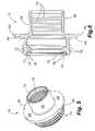
- FIG. 3is an exploded perspective view of the lock nut group of the present invention.
- FIG. 4is an enlarged vertical section of an assembled lock nut group in accordance with the construction of FIG. 3 ;
- FIG. 5is an enlarged perspective view of a threaded flange
- FIG. 6is a greatly enlarged vertical section of the threaded flange of FIG. 5 ;
- FIG. 7is an enlarged perspective view of a standard flange
- FIG. 8is a greatly enlarged vertical section of the standard flange of FIG. 7 ;
- FIG. 9is a greatly enlarged vertical section of the coupling assembly of the present invention joining confronting ends of first and second conduit members;
- FIG. 10is a greatly enlarged vertical section of the coupling assembly of the present invention showing the coupling assembly in an unlocked position
- FIG. 11is an elevation or side view of the coupling assembly showing the coupling assembly in a locked position.
- FIGS. 1 and 2illustrate the coupling assembly 10 of the present invention for rigidly connecting confronting ends of two conduit members.
- Basic or primary components of the coupling assemblyinclude a threaded flange or first coupling member 14 , a lock nut group or second coupling member 12 , a standard flange 16 , an o-ring 18 positioned between a facing surface of the standard flange and a facing surface of the threaded flange, and a rigid connecting means or flat washer 20 that is positioned at the interface between the lock nut group and the standard flange.
- Assembly of the coupling assemblyincludes placement of the flat washer 20 within the lock nut group and alignment with the opening of the lock nut group, and positioning the lock nut group over the standard flange so that when assembled, the flat washer 20 is trapped between an exterior rib or shoulder 80 of the standard flange and an interior shoulder 45 of the nut body 44 , as further discussed below.
- the o-ring 18is received within an annular groove or recess 76 ( FIG. 6 ) formed on facing surface 74 of the threaded flange.
- the facing surface 82 of the standard flangeFIG. 7 ) compresses the o-ring 18 as the lock nut group is drawn toward the threaded flange by rotating the lock nut group in the locking direction by engagement of interior threads 56 of the lock nut group with exterior threads 72 of the threaded flange.
- the pair of slots or reliefs 40 formed on the peripheral edge of the lock nut group 12align with and engage the projections or tabs 66 formed on the rim or peripheral edge of the threaded flange.
- the lock ring 30is characterized by an outer rim 32 that may be roughened or knurled, a rim extension 33 that extends axially away from the outer rim 32 , and one or more notches or reliefs 40 that engage corresponding projections or tabs 66 on the threaded flange when the coupling is in the locked position. Additionally, the interior surface of the lock ring includes one or more keys or projections 38 that align with corresponding key ways or slots 48 formed on the outer rim 46 of the lock nut 44 . The nut body is inserted coaxially within the lock ring so that the keys and key ways are aligned.
- Lock ring 30is attached to nut body 44 as by a split retainer 60 that is received within an annular slot or groove 34 formed on the interior surface of the lock ring 30 .
- the split retainer 60is reduced in circumference by first closing the ends 61 towards one another, placing the split retainer 60 within the groove 34 , and then releasing the ends 61 whereby the split retainer returns to its undeformed state with an enlarged circumference and thereby being held within the groove 34 .
- the structure of the nut body 44is further characterized as including an interior shoulder 50 , an exterior shoulder 52 , and an axial extension 54 interconnecting the interior and exterior shoulders.
- the inner surface of the nut groupincludes threads 56 which are threaded over the exterior threads 72 of the threaded flange, as further discussed below.
- a biasing membershown in the preferred embodiment as a wave spring 58 , is provided for biased relative axial displacement between the lock ring and nut body.
- the wave springPrior to inserting the nut body in the lock ring, the wave spring is positioned over the extension 54 .
- the spring 58is maintained in the gap or space between the lock ring and the nut body. This gap or space is delimited annularly by the extension 54 and the interior surface 36 of the lock ring. This gap or space is delimited axially by the split retainer 60 and by the interior shoulder 50 .
- biased axial movementis allowed between the lock ring and nut body to the extent that the spring 58 can be compressed and decompressed in the gap or space, yet relative rotational movement of the lock ring and nut body are prevented by the key and key way arrangement.
- the threaded flange 14is characterized by a protruding rim 64 , and one or more projection tabs 66 which are spaced from one another in the same spacing as the notches 40 .
- a pair of tabs and notchesare present.
- the tabs and notchesare spaced from one another approximately 180 degrees.
- a sleeve 68extends axially from the rim 64 in one direction, and external threads 72 extend from the rim 64 in the opposite axial direction.
- the interior surface of the sleeve 68includes a plurality of swaging grooves 70 , and the first conduit 22 preferably attached to the threaded flange as by a swaging operation wherein the free end of the conduit member is swaged with respect to the interior surface of the sleeve 68 .
- the threaded flange 14further includes a facing surface 74 , and an annular groove or slot 76 that is formed on the face 74 .
- the annular groove 76is sized to receive the o-ring 18 .
- the standard flange 16includes a rib 80 , a contact face or surface 82 , and a sleeve 84 .
- the interior surface of the standard flangealso preferably includes swaging grooves 86 wherein the free end of the second conduit member 24 is preferably swaged with respect to the interior surface of the sleeve 84 .
- FIGS. 9 and 10the coupling assembly is illustrated when assembled.
- FIG. 9more specifically illustrates the lock nut group threaded over the threads of the threaded flange, but the lock ring has not yet snap fit into the locked position, thus, some gap g exists between the facing surface of the rim extension 33 and the tabs 66 . Accordingly, the spring is still compressed in the gap or space between the nut body and the lock ring. As also shown, the flat washer 20 is trapped between the exterior shoulder 17 of the standard flange and the interior shoulder 45 of the nut body.
- the o-ring 18is positioned in the annular groove 76 of the threaded flange, and the facing surface 82 of the standard flange fits in the annular groove and compresses the o-ring thereby creating a leak proof seal.
- the lock ringhas been displaced by the force from the spring 58 so that the notches 40 are engaged with the respective tabs 66 .
- FIG. 11also illustrates the coupling in the locked position.
- the exterior threads 72 on the threaded flange and the interior threads 56 on the nut bodyare clocked so that a desired number of rotations of the lock nut group allows the notches 40 to snap fit in engagement with the tabs 66 .
- an indicator stripein the form of a florescent colored annular marking may be placed around the portion of the peripheral surface of the rim 64 that becomes covered by the lock ring when the coupling is placed in the locked position.
- an indicator stripe or markingdisappears, this indicates to a user that the coupling is locked and ready for operation.
- the rigid nature of the attachment between the conduit membersis further enhanced by the close tolerance fit between the peripheral outer edge or surface 81 of the standard flange with respect to the inner circumferential facing edge 73 .
- FIGS. 9 and 10there is substantial continuous contact between the components of the coupling assembly which bypass the o-ring thereby providing an electrically conductive path that eliminates electrostatic potential between the conduit members.
- the pathis defined by contact of the standard flange with the flat washer 20 , contact of the flat washer with the lock nut group, and contact of the lock nut group with the standard flange by the threaded arrangement.
- the o-ring 18provides a seal between the standard flange and the threaded flange, metal to metal contact is still achieved across this sealed interface by the electrical conductive path, thereby eliminating the need for an externally mounted bonding strap that is typically used to maintain electrical continuity.
- the lock ringWhen it is desired to unlock the coupling assembly, the lock ring is pulled axially away from the rim 64 of the threaded flange by grasping the outer rim 32 , and then the lock nut group is rotated in an unlocking direction thereby unscrewing the lock nut group from the threaded flange.
- the coupling assembly of the present inventionprovides a reliable and structurally stable connection.
- the connectionis rigid thereby eliminating the need for support hangars at or adjacent the coupling.
- the couplingis easily installed and requires no bonding strap.
- the coupling assemblyis easily maintained because it can be disassembled down to a component level for inspection and for component replacement as necessary.
Landscapes
- Engineering & Computer Science (AREA)
- General Engineering & Computer Science (AREA)
- Mechanical Engineering (AREA)
- Quick-Acting Or Multi-Walled Pipe Joints (AREA)
- Joints Allowing Movement (AREA)
Abstract
Description
Claims (15)
Priority Applications (3)
| Application Number | Priority Date | Filing Date | Title |
|---|---|---|---|
| US11/210,641US7222889B2 (en) | 2005-08-23 | 2005-08-23 | Self-locking self-bonding rigid coupling |
| EP20060802066EP1924800B1 (en) | 2005-08-23 | 2006-08-22 | Self-locking self-bonding rigid coupling |
| PCT/US2006/032741WO2007024842A2 (en) | 2005-08-23 | 2006-08-22 | Self-locking self-bonding rigid coupling |
Applications Claiming Priority (1)
| Application Number | Priority Date | Filing Date | Title |
|---|---|---|---|
| US11/210,641US7222889B2 (en) | 2005-08-23 | 2005-08-23 | Self-locking self-bonding rigid coupling |
Publications (2)
| Publication Number | Publication Date |
|---|---|
| US20070052234A1 US20070052234A1 (en) | 2007-03-08 |
| US7222889B2true US7222889B2 (en) | 2007-05-29 |
Family
ID=37772277
Family Applications (1)
| Application Number | Title | Priority Date | Filing Date |
|---|---|---|---|
| US11/210,641Active2025-11-23US7222889B2 (en) | 2005-08-23 | 2005-08-23 | Self-locking self-bonding rigid coupling |
Country Status (3)
| Country | Link |
|---|---|
| US (1) | US7222889B2 (en) |
| EP (1) | EP1924800B1 (en) |
| WO (1) | WO2007024842A2 (en) |
Cited By (18)
| Publication number | Priority date | Publication date | Assignee | Title |
|---|---|---|---|---|
| US20080141978A1 (en)* | 2006-12-13 | 2008-06-19 | Wenbin Xu | O-ring retainer for a fuel injector in a fuel rail socket |
| US20090039648A1 (en)* | 2007-08-10 | 2009-02-12 | Su-Young Lee | Water supply hose connector for washing machine |
| US20090044655A1 (en)* | 2007-07-05 | 2009-02-19 | Re2, Inc. | Defense Related Robotic Systems |
| US20110121566A1 (en)* | 2009-11-20 | 2011-05-26 | Cowell Jason M | Glueless plumbing union |
| US20110148098A1 (en)* | 2009-12-18 | 2011-06-23 | Flynn William T | Compliant conduit connector |
| US20130327888A1 (en)* | 2012-06-08 | 2013-12-12 | The Boeing Company | Conductive Coupling Assembly |
| US8808019B2 (en) | 2010-11-01 | 2014-08-19 | Amphenol Corporation | Electrical connector with grounding member |
| US9145993B1 (en) | 2012-10-22 | 2015-09-29 | The Boeing Company | Non-metallic fluid coupling assemblies |
| US9468872B2 (en) | 2012-10-01 | 2016-10-18 | Entegris, Inc. | Purification system with manifold assembly and removable filter cassette |
| WO2017034715A1 (en)* | 2015-08-21 | 2017-03-02 | Eaton Corporation | Fluid coupling and method of assembly |
| US20170152975A1 (en)* | 2015-11-30 | 2017-06-01 | Yi-Chuan Huang | Rotatable connector for connecting a fluid transmission pipe |
| US9797535B2 (en) | 2013-04-16 | 2017-10-24 | Eaton Corporation | Bonding clip for fluid conduit coupling |
| US20170370511A1 (en)* | 2016-06-24 | 2017-12-28 | Eaton Corporation | Fluid couplings, systems, and methods |
| US9943789B2 (en) | 2011-10-03 | 2018-04-17 | Entegris, Inc. | Modular filter cassette |
| US10119635B2 (en) | 2013-03-08 | 2018-11-06 | United Technologies Corporation | Locking fluid fittings |
| US10760363B2 (en) | 2018-02-19 | 2020-09-01 | Baker Hughes, A Ge Company, Llc | Lock ring segments biased into locked position while retained in position with an exterior profile |
| US11236851B1 (en) | 2021-04-06 | 2022-02-01 | Trinity Bay Equipment Holdings, LLC | Quick connect pipe fitting systems and methods |
| US20220136627A1 (en)* | 2020-11-03 | 2022-05-05 | The Boeing Company | Compression fitting with visual torque indicator |
Families Citing this family (19)
| Publication number | Priority date | Publication date | Assignee | Title |
|---|---|---|---|---|
| US7810851B2 (en)* | 2008-05-29 | 2010-10-12 | Orbit Irrigation Products, Inc. | Wrenchless manifold |
| US20100019492A1 (en)* | 2008-07-24 | 2010-01-28 | Richards Timothy J | Tube Connector for Intake Manifold |
| FR2934843B1 (en)* | 2008-08-06 | 2011-03-18 | Spirotechnique | REQUIRED VALVE DEVICE FOR DIVERTER AND SELECTIVELY CONNECTABLE FLUID LINK MEMBER. |
| US8356843B2 (en) | 2010-09-27 | 2013-01-22 | Hamilton Sundstrand Corporation | Refrigeration system connection fitting |
| CN105605269A (en)* | 2013-10-23 | 2016-05-25 | 南安市丽迪家居用品有限公司 | Water-saving connector capable of adjusting maximum water flow |
| US11262013B2 (en) | 2014-01-14 | 2022-03-01 | The Boeing Company | Tube fitting |
| US10359141B2 (en) | 2014-01-14 | 2019-07-23 | The Boeing Company | Tube fitting |
| US10060563B2 (en)* | 2014-01-14 | 2018-08-28 | The Boeing Company | Tube fitting |
| US9939095B2 (en) | 2014-01-29 | 2018-04-10 | The Boeing Company | Tube fitting |
| WO2015119948A1 (en)* | 2014-02-04 | 2015-08-13 | Entegris, Inc. | Connection system and method |
| US9593700B2 (en)* | 2014-10-03 | 2017-03-14 | Kurt Kevin Bynum | Self-locking plug |
| US9909446B2 (en)* | 2014-10-03 | 2018-03-06 | Kurt Kevin Bynum | Self-locking plug |
| US9781886B1 (en) | 2014-12-19 | 2017-10-10 | Orbit Irrigation Products, Inc. | Hand-securable sprinkler fitting |
| WO2017026898A1 (en)* | 2015-08-10 | 2017-02-16 | Thor Frölich Braathen | A fitting to connect water pipes |
| TWM544036U (en)* | 2017-02-15 | 2017-06-21 | Thermaltake Technology Co Ltd | Pipe joint structure |
| WO2019014571A1 (en)* | 2017-07-14 | 2019-01-17 | Nite Ize, Inc. | Systems and methods for a 360 degree rotating and detachable double carabiner |
| US11300234B2 (en) | 2017-08-07 | 2022-04-12 | Eaton Intelligent Power Limited | Fluid fitting |
| US11306852B2 (en)* | 2017-08-07 | 2022-04-19 | Eaton Intelligent Power Limited | Fluid fitting |
| WO2020198021A1 (en)* | 2019-03-27 | 2020-10-01 | Hoffman Enclosures, Inc. | Threaded coupler systems and methods |
Citations (15)
| Publication number | Priority date | Publication date | Assignee | Title |
|---|---|---|---|---|
| US3669472A (en) | 1971-02-03 | 1972-06-13 | Wiggins Inc E B | Coupling device with spring locking detent means |
| US3999825A (en) | 1975-12-17 | 1976-12-28 | De Laval Turbine Inc. | Tubing coupling with electrical bonding |
| US4008937A (en) | 1974-09-20 | 1977-02-22 | Stanley Aviation Corporation | Coupling assembly |
| US4249786A (en) | 1978-11-03 | 1981-02-10 | Hydraflow Supply, Inc. | Flexible coupling |
| US4285564A (en) | 1978-09-19 | 1981-08-25 | Georg Spinner | HF Coaxial plug connector |
| US4346428A (en) | 1980-06-05 | 1982-08-24 | Stanley Aviation Corp. | Coupling assembly with bonding jumper |
| US4808117A (en) | 1987-09-08 | 1989-02-28 | Stanley Aviation Corporation | Coupler with combination locking and bonding ring |
| US4881760A (en) | 1988-11-07 | 1989-11-21 | Stanley Aviation Corporation | Conduit coupling device with redundancy features |
| US4900070A (en) | 1989-02-21 | 1990-02-13 | Stanley Aviation Corporation | Conduit coupling device with redundancy features |
| US4928202A (en) | 1988-12-12 | 1990-05-22 | Stanley Aviation Corporation | Coupler with combination locking and bonding ring |
| EP0412677A2 (en) | 1989-08-08 | 1991-02-13 | Anson Limited | Pipeline coupling |
| WO1998019095A1 (en) | 1996-10-31 | 1998-05-07 | Stanley Aviation Corporation | Positive lock coupling |
| US6050609A (en) | 1996-10-31 | 2000-04-18 | Stanley Aviation Corporation | Positive lock coupling |
| US6073973A (en) | 1996-10-31 | 2000-06-13 | Stanley Aviation Corporation | Lightweight positive lock coupling |
| US6883836B2 (en) | 2003-01-17 | 2005-04-26 | Stanley Aviation Corporation | Positive locking fitting assembly |
Family Cites Families (9)
| Publication number | Priority date | Publication date | Assignee | Title |
|---|---|---|---|---|
| US1580694A (en) | 1925-03-12 | 1926-04-13 | Harvey K Russell | Pipe coupling |
| FR917287A (en)* | 1945-07-09 | 1946-12-31 | Safety brake for assembly of coaxial elements | |
| GB1140390A (en)* | 1966-08-05 | 1969-01-15 | Adams Ltd L | Quick release couplings for fluid, flow lines or pipes |
| GB1152093A (en)* | 1967-01-24 | 1969-05-14 | H K Porter Company Great Brita | Couplings for Fluid Lines |
| US4009937A (en)* | 1975-09-08 | 1977-03-01 | Owens-Illinois, Inc. | Multiplex addressing of colloidal light valves |
| US4665960A (en)* | 1985-03-04 | 1987-05-19 | Cajon Company | Coded coupling |
| JPS63180790A (en)* | 1987-01-23 | 1988-07-25 | 東海ゴム工業株式会社 | Pipe joint |
| GB2228981A (en)* | 1989-03-11 | 1990-09-12 | Iracroft Ltd | Providing a threaded connection between two tubes |
| US5188398A (en)* | 1992-01-02 | 1993-02-23 | General Electric Company | Redundantly locked fluid coupling |
- 2005
- 2005-08-23USUS11/210,641patent/US7222889B2/enactiveActive
- 2006
- 2006-08-22EPEP20060802066patent/EP1924800B1/enactiveActive
- 2006-08-22WOPCT/US2006/032741patent/WO2007024842A2/enactiveApplication Filing
Patent Citations (16)
| Publication number | Priority date | Publication date | Assignee | Title |
|---|---|---|---|---|
| US3669472A (en) | 1971-02-03 | 1972-06-13 | Wiggins Inc E B | Coupling device with spring locking detent means |
| US4008937A (en) | 1974-09-20 | 1977-02-22 | Stanley Aviation Corporation | Coupling assembly |
| US3999825A (en) | 1975-12-17 | 1976-12-28 | De Laval Turbine Inc. | Tubing coupling with electrical bonding |
| US4285564A (en) | 1978-09-19 | 1981-08-25 | Georg Spinner | HF Coaxial plug connector |
| US4249786A (en) | 1978-11-03 | 1981-02-10 | Hydraflow Supply, Inc. | Flexible coupling |
| US4346428A (en) | 1980-06-05 | 1982-08-24 | Stanley Aviation Corp. | Coupling assembly with bonding jumper |
| US4808117A (en) | 1987-09-08 | 1989-02-28 | Stanley Aviation Corporation | Coupler with combination locking and bonding ring |
| US4881760A (en) | 1988-11-07 | 1989-11-21 | Stanley Aviation Corporation | Conduit coupling device with redundancy features |
| US4928202A (en) | 1988-12-12 | 1990-05-22 | Stanley Aviation Corporation | Coupler with combination locking and bonding ring |
| US4900070A (en) | 1989-02-21 | 1990-02-13 | Stanley Aviation Corporation | Conduit coupling device with redundancy features |
| EP0412677A2 (en) | 1989-08-08 | 1991-02-13 | Anson Limited | Pipeline coupling |
| WO1998019095A1 (en) | 1996-10-31 | 1998-05-07 | Stanley Aviation Corporation | Positive lock coupling |
| US5871239A (en) | 1996-10-31 | 1999-02-16 | Stanley Aviation Corporation | Positive lock coupling |
| US6050609A (en) | 1996-10-31 | 2000-04-18 | Stanley Aviation Corporation | Positive lock coupling |
| US6073973A (en) | 1996-10-31 | 2000-06-13 | Stanley Aviation Corporation | Lightweight positive lock coupling |
| US6883836B2 (en) | 2003-01-17 | 2005-04-26 | Stanley Aviation Corporation | Positive locking fitting assembly |
Non-Patent Citations (1)
| Title |
|---|
| SAE AS1730 Aerospace Standard Coupling, Fuel, Rigid Threaded Type; Issued Sep. 1982, Reaffirmed Apr. 1996. |
Cited By (32)
| Publication number | Priority date | Publication date | Assignee | Title |
|---|---|---|---|---|
| US7455050B2 (en)* | 2006-12-13 | 2008-11-25 | Delphi Technologies, Inc. | O-ring retainer for a fuel injector in a fuel rail socket |
| US20080141978A1 (en)* | 2006-12-13 | 2008-06-19 | Wenbin Xu | O-ring retainer for a fuel injector in a fuel rail socket |
| US20090044655A1 (en)* | 2007-07-05 | 2009-02-19 | Re2, Inc. | Defense Related Robotic Systems |
| US10272575B2 (en) | 2007-07-05 | 2019-04-30 | Re2, Inc. | Defense related robotic systems |
| US9144909B2 (en)* | 2007-07-05 | 2015-09-29 | Re2, Inc. | Defense related robotic systems |
| US20090039648A1 (en)* | 2007-08-10 | 2009-02-12 | Su-Young Lee | Water supply hose connector for washing machine |
| US20110121566A1 (en)* | 2009-11-20 | 2011-05-26 | Cowell Jason M | Glueless plumbing union |
| US8534716B2 (en)* | 2009-11-20 | 2013-09-17 | Pentair Water Pool & Spa, Inc. | Glueless plumbing union |
| US20110148098A1 (en)* | 2009-12-18 | 2011-06-23 | Flynn William T | Compliant conduit connector |
| US8360477B2 (en) | 2009-12-18 | 2013-01-29 | Eaton Corporation | Compliant conduit connector |
| US8808019B2 (en) | 2010-11-01 | 2014-08-19 | Amphenol Corporation | Electrical connector with grounding member |
| US9943789B2 (en) | 2011-10-03 | 2018-04-17 | Entegris, Inc. | Modular filter cassette |
| US20130327888A1 (en)* | 2012-06-08 | 2013-12-12 | The Boeing Company | Conductive Coupling Assembly |
| US9162774B2 (en) | 2012-06-08 | 2015-10-20 | The Boeing Company | Fluid transport system for preventing electrical discharge |
| US10633111B2 (en) | 2012-06-08 | 2020-04-28 | The Boeing Company | Composite tubes for a fluid transport system |
| US9169029B2 (en)* | 2012-06-08 | 2015-10-27 | The Boeing Company | Conductive coupling assembly |
| US9688419B2 (en) | 2012-06-08 | 2017-06-27 | The Boeing Company | Composite tubes for a fluid transport system |
| US9802142B2 (en) | 2012-10-01 | 2017-10-31 | Entegris, Inc. | Purifier cassette |
| US9468872B2 (en) | 2012-10-01 | 2016-10-18 | Entegris, Inc. | Purification system with manifold assembly and removable filter cassette |
| US9145993B1 (en) | 2012-10-22 | 2015-09-29 | The Boeing Company | Non-metallic fluid coupling assemblies |
| US10119635B2 (en) | 2013-03-08 | 2018-11-06 | United Technologies Corporation | Locking fluid fittings |
| US9797535B2 (en) | 2013-04-16 | 2017-10-24 | Eaton Corporation | Bonding clip for fluid conduit coupling |
| US11187355B2 (en) | 2015-08-21 | 2021-11-30 | Eaton Intelligent Power Limited | Fluid coupling and method of assembly |
| WO2017034715A1 (en)* | 2015-08-21 | 2017-03-02 | Eaton Corporation | Fluid coupling and method of assembly |
| US20180238477A1 (en)* | 2015-08-21 | 2018-08-23 | Eaton Intelligent Power Limited | Fluid coupling and method of assembly |
| US20170152975A1 (en)* | 2015-11-30 | 2017-06-01 | Yi-Chuan Huang | Rotatable connector for connecting a fluid transmission pipe |
| US20170370511A1 (en)* | 2016-06-24 | 2017-12-28 | Eaton Corporation | Fluid couplings, systems, and methods |
| US10883640B2 (en)* | 2016-06-24 | 2021-01-05 | Eaton Intelligent Power Limited | Fluid couplings, systems, and methods |
| US10760363B2 (en) | 2018-02-19 | 2020-09-01 | Baker Hughes, A Ge Company, Llc | Lock ring segments biased into locked position while retained in position with an exterior profile |
| US20220136627A1 (en)* | 2020-11-03 | 2022-05-05 | The Boeing Company | Compression fitting with visual torque indicator |
| US11815202B2 (en)* | 2020-11-03 | 2023-11-14 | The Boeing Company | Compression fitting with visual torque indicator |
| US11236851B1 (en) | 2021-04-06 | 2022-02-01 | Trinity Bay Equipment Holdings, LLC | Quick connect pipe fitting systems and methods |
Also Published As
| Publication number | Publication date |
|---|---|
| EP1924800B1 (en) | 2013-07-03 |
| WO2007024842A2 (en) | 2007-03-01 |
| WO2007024842A3 (en) | 2007-05-18 |
| EP1924800A4 (en) | 2011-03-16 |
| US20070052234A1 (en) | 2007-03-08 |
| EP1924800A2 (en) | 2008-05-28 |
Similar Documents
| Publication | Publication Date | Title |
|---|---|---|
| US7222889B2 (en) | Self-locking self-bonding rigid coupling | |
| US6883836B2 (en) | Positive locking fitting assembly | |
| US8075024B2 (en) | Coupling assembly | |
| US6086400A (en) | Self-locking cable connector coupling | |
| US6358077B1 (en) | G-load coupling nut | |
| US3669472A (en) | Coupling device with spring locking detent means | |
| US6050609A (en) | Positive lock coupling | |
| EP1073859B1 (en) | Lightweight positive lock coupling | |
| US11067211B2 (en) | Aircraft fluid line coupling assembly for releasably interconnecting fluid conveying members | |
| US6086118A (en) | Quick connect tubing connector | |
| US7862090B1 (en) | Plug-in fitting for direct connection to housing | |
| US7040670B2 (en) | Coupling apparatus | |
| US6602085B2 (en) | G-load coupling nut | |
| IL129212A (en) | Positive lock coupling | |
| US8215678B2 (en) | Connector for a pipe and bonding means for use therein | |
| US3891290A (en) | Washer for electrically connecting the tubes of a fluid line | |
| EP2913550B1 (en) | Spline lock shaft locking system | |
| WO2014143501A1 (en) | Concentric slide clamshell coupler | |
| US20200217370A1 (en) | System and method for axially retaining two coaxial shaft components | |
| CN113964590A (en) | A quick-connect anti-return sealing mechanism | |
| EP0760070A1 (en) | Retainer arrangement for extreme load applications | |
| WO2018237033A1 (en) | Quick connect sensor assembly | |
| EP1724511B1 (en) | Quick connector with a retainer |
Legal Events
| Date | Code | Title | Description |
|---|---|---|---|
| AS | Assignment | Owner name:STANLEY AVIATION CORPORATION, COLORADO Free format text:ASSIGNMENT OF ASSIGNORS INTEREST;ASSIGNOR:BREAY, CLIFTON P.;REEL/FRAME:017320/0822 Effective date:20050823 | |
| STCF | Information on status: patent grant | Free format text:PATENTED CASE | |
| FPAY | Fee payment | Year of fee payment:4 | |
| FPAY | Fee payment | Year of fee payment:8 | |
| MAFP | Maintenance fee payment | Free format text:PAYMENT OF MAINTENANCE FEE, 12TH YEAR, LARGE ENTITY (ORIGINAL EVENT CODE: M1553); ENTITY STATUS OF PATENT OWNER: LARGE ENTITY Year of fee payment:12 | |
| AS | Assignment | Owner name:EATON INTELLIGENT POWER LIMITED, IRELAND Free format text:ASSIGNMENT OF ASSIGNORS INTEREST;ASSIGNOR:EATON AEROQUIP LLC;REEL/FRAME:047441/0413 Effective date:20171231 Owner name:EATON AEROQUIP LLC, OHIO Free format text:MERGER;ASSIGNOR:EATON AVIATION CORPORATION;REEL/FRAME:047441/0384 Effective date:20081128 Owner name:EATON AVIATION CORPORATION, OHIO Free format text:CHANGE OF NAME;ASSIGNOR:STANLEY AVIATION CORPORATION;REEL/FRAME:047446/0835 Effective date:20051123 |