US7221377B1 - Apparatus and method for collecting and displaying information in a workflow system - Google Patents
Apparatus and method for collecting and displaying information in a workflow systemDownload PDFInfo
- Publication number
- US7221377B1 US7221377B1US09/557,264US55726400AUS7221377B1US 7221377 B1US7221377 B1US 7221377B1US 55726400 AUS55726400 AUS 55726400AUS 7221377 B1US7221377 B1US 7221377B1
- Authority
- US
- United States
- Prior art keywords
- workflow
- execution
- event
- statistics
- displaying
- Prior art date
- Legal status (The legal status is an assumption and is not a legal conclusion. Google has not performed a legal analysis and makes no representation as to the accuracy of the status listed.)
- Expired - Lifetime
Links
Images


Classifications
- G—PHYSICS
- G06—COMPUTING OR CALCULATING; COUNTING
- G06Q—INFORMATION AND COMMUNICATION TECHNOLOGY [ICT] SPECIALLY ADAPTED FOR ADMINISTRATIVE, COMMERCIAL, FINANCIAL, MANAGERIAL OR SUPERVISORY PURPOSES; SYSTEMS OR METHODS SPECIALLY ADAPTED FOR ADMINISTRATIVE, COMMERCIAL, FINANCIAL, MANAGERIAL OR SUPERVISORY PURPOSES, NOT OTHERWISE PROVIDED FOR
- G06Q10/00—Administration; Management
- G06Q10/06—Resources, workflows, human or project management; Enterprise or organisation planning; Enterprise or organisation modelling
Definitions
- This inventionrelates to the field of transaction processing.
- this inventionis drawn to an apparatus and method for collecting and displaying information in a workflow system.
- the systemis capable of managing various tasks, including transaction routing, such as telephone call routing, e-mail routing, web request routing, etc.
- transaction routingsuch as telephone call routing, e-mail routing, web request routing, etc.
- a typical transaction processing systemis equipped to receive transaction requests, or events (e.g., calls, e-mails, network requests, etc.) over a variety of media, and to process and facilitate transactions between the source of the event and an agent responsive to such a request.
- one or more administrative clientsis configured with workflow definitions that define workflows that are executed by one or more workflow server engines. In this way, when a pre-defined event is received by the transaction processing system, the transaction processing system executes a workflow which has been previously configured.
- One problem with prior art transaction processing systemsrelates to the difficulty in handling new types of events.
- a transaction processing systemWhen a transaction processing system is set up, it is capable of handling various types of events and executing workflows in response to the events.
- the core workflow server enginemust be recompiled.
- the transaction processing systemis inflexible and can not be customized very easily. It would be desirable to provide a transaction processing system which is extensible so that new kinds of events can be handled without changing the core workflow execution method.
- a method of the present inventionis provided for displaying information relating to a workflow including the steps of executing the workflow, gathering statistical information relating to the execution of the workflow, and displaying the gathered information.
- a workflow systemincluding a workflow server engine for executing workflows, a display device for displaying workflow diagrams, and an overlay data provider for providing information relating to an executing workflow to the display.
- Another embodimentprovides a method of collecting information relating to a workflow including the steps of executing the workflow and collecting information relating to the execution of the workflow.
- FIG. 1is a block diagram illustrating a transaction processing system environment.
- FIG. 2is a block diagram illustrating an exemplary transaction processing environment in the form of a call center environment.
- FIG. 3is a block diagram illustrating a call center site having an alternative architecture.
- FIG. 4is a block diagram of a workflow server of the present invention.
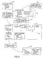
- FIG. 5is a flowchart illustrating one example of a process of adding an event source to a transaction processing system.
- FIGS. 6 and 7are block diagrams of workflow servers of the present invention.
- FIG. 8is a block diagram which illustrates how a workflow is invoked in response to an event in a workflow server of the present invention.
- FIG. 9is a block diagram illustrating how a workflow server engine executes a step implemented using ActiveX controls.
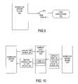
- FIG. 10is a block functional block diagram illustrating the overlay of workflow statistical information onto a workflow diagram.
- FIGS. 11 and 12are diagrams of an exemplary workflow illustrating the overlay of statistical data onto a workflow diagram.
- FIG. 13is a diagram illustrating a centralized configuration database for use with a plurality of workflow server engines.
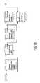
- FIG. 14is a block diagram illustrating the loading and unloading of workflow rule sets.
- FIG. 15is a workflow diagram illustrating an exception handling mechanism.
- the present inventionallows a user of a transaction processing system, such as a customer relationship management (CRM) tool or an automatic call distribution (ACD), for example, to easily add new event sources without recompiling the core workflow server engine of the transaction processing system.
- CRMcustomer relationship management
- ACDautomatic call distribution
- the inventionuses standards-based, extensible components (e.g., ActiveX controls), which makes the implementation of the invention advantageous over prior art systems (described in detail below).
- ActiveX controlse.g., ActiveX controls
- workflowis intended to mean a sequence of steps that are performed to, at least partially, process a transaction.
- workflowis intended to designate a form of business rule processing.
- workflowsare directed graphs having a plurality of vertices (steps) connected to each other with edges (connectors) to symbolically depict business rules and how the business rules handle events and other inputs.
- Workflowsare created using a workflow editor which is described below.
- Workflowsare stored in some sort of file system or database for use by a workflow server engine.
- Workflowsare typically associated with one or more events from a given event source, thereby allowing a workflow designer the choice of using event parameters in the business logic.
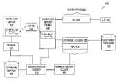
- FIG. 1is a block diagram illustrating a transaction processing system environment 100 including a workflow server engine 110 connected to a network 112 .
- the network 112could be comprised of any suitable network such as a LAN, WAN, MAN, etc.
- the function of the workflow server engine 110is to execute transaction tasks, in response to an event, using workflow-driven business rules 114 .
- Sources of eventsare provided by several systems including CTI server 116 , fax server 118 , email server 120 , and web server 122 . As described below, other types of event sources may also provide sources for events.
- FIG. 1also shows an automatic call distributor (ACD) 124 and a database server 126 connected to the network 112 .
- ACDautomatic call distributor
- One or more agent desktop clients 128are also connected to the network 112 .
- the workflow server engine 110When an event is received from one or more of the event sources, the workflow server engine 110 responds to the event based on the workflow-driven business rules 114 . Depending on the business rules, the response may include various steps including routing a query to one of the agent desktop clients 128 , automatically responding to the event, etc.
- the workflow-driven business rules 114may be a simple process or may be a complex process with multiple steps and the exchange of information between the workflow server engine 110 and the event source. To help understand the present invention, following is a more detailed description of the operation of the workflow server engine 110 .
- a transaction processing system of the present inventionsuch as for example an ACD, is used for executing a transaction task.
- the transaction processing subsystemmay be dedicated to performing a specific task within the transaction processing system, such as for example transaction routing. Examples of transaction routing include telephone call routing, e-mail routing, and Web request routing from an event source to a software or human agent.
- FIG. 2is a block diagram illustrating an exemplary transaction processing environment 200 , in the form of a call center environment.
- FIG. 2provides an enterprise-wide view of a transaction processing environment 200 that includes a call center site 202 that may be coupled via a network 212 and to customer enterprise systems 230 , an enterprise workflow server 232 , and an information server 234 .
- the customer enterprise systems 230may execute host-based Computer Telephony Integration (CTI) applications, such as “screen pops” and database lookup applications.
- CTIComputer Telephony Integration
- the pre-routing workflow server 232may perform a “pre-call routing” function.
- the workflow server 232may collect information from multiple call center sites in a multi-site heterogeneous or homogeneous call center environment, interpret this information, and provide routing information to a Service Control Point (SCP) regarding where to route a call based on the call center site data and user preferences.
- SCPService Control Point
- the workflow server 232provides a framework for a single system image view of resources on multiple call center sites, and the capability to route a call to a specific call center site based on resources, skills and agent availability at the multiple call center sites. Such routing decisions may be based on near real-time data collected from the respective call center sites, and on the routing preferences specified by users.
- the information server 234also provides real-time and enterprise-wide information to call center system administrator, and may also gather information for the purposes of near real-time management of the call center environment shown in FIG. 2 .
- the call center site 202is equipped to receive transaction requests (e.g., calls, e-mails, network requests, etc.) over a variety of media, and to process and facilitate transactions between, for example, a source and a human (or software) agent responsive to such transaction requests.
- the call center site 202is shown to include a number of transaction processing systems, namely an e-mail server 220 , a web server 222 , an Interactive Voice Response (IVR) workflow server 236 , an ACD 224 , a Computer Telephony Integration (CTI) server 216 and a workflow server 210 .
- the call center site 202is also shown to include a telephony device server 238 , an agent access server 240 and agent desktop clients 228 .
- the ACD 224is also shown to include call processing functionality 242 , whereby telephone calls (e.g., both switched and voice-over-IP calls) may be processed and routed to an available agent teleset (not shown).
- the call center site 202includes a number of administrative clients 244 , whereby a call center site administrator may configure and edit workflow definitions that define workflows that are executed by various workflow servers within the respective call center sites.
- a call center site administratormay configure and edit workflow definitions that define workflows that are executed by various workflow servers within the respective call center sites.
- a detailed description describing how workflow definitions can be editedis described in commonly-owned co-pending patent application entitled “VISUAL DESIGN OF WORKFLOWS FOR TRANSACTION PROCESSING”, filed on Dec. 2, 1997, and incorporated by reference herein.
- FIG. 3is a block diagram illustrating a call center site 302 , according to an exemplary embodiment of the present invention, having an alternative architecture to the call center site 202 illustrated in FIG. 2 .
- the workflow server engines for directing and routing calls within an environment which has multiple call center sitesare shown to be distributed over a number of transaction processing systems, such as the workflow server 210 , the IVR workflow server 236 , a call center customer relationship server 346 , and the CTI server 216 .
- the call center site 302 illustrated in FIG. 3provides a more integrated environment in which a single workflow server engine 348 within the server 346 routes transaction information over a wide variety of media.
- the workflow server engine 348is a provided with “events” by a number of event subsystems 350 that receive input from a number of servers, such as for example in the e-mail server 320 , the web server 322 , and a video server 352 .
- the event subsystem 350also provides events to the workflow server engine 348 resulting from telephone calls received at a telephony device server 338 via the Public Switched Telephone Network (PSTN) 356 or via the Internet 354 .
- PSTNPublic Switched Telephone Network
- the call center site 302includes a number of agent stations 358 , each of which may include a teleset 360 by which a human agent may respond to transaction requests received via any of the media servers and a collection of agent desktop applications 362 for facilitating transaction processing over, for example, the Internet utilizing e-mail or the World Wide Web (WWW).
- the agent desktop applications 362may include an e-mail client, a browser client, a web collaboration client and a video conferencing client. These agent desktop applications may be highly integrated, or may be stand-alone applications.
- each agent station 358may comprise a software agent, which is able to respond to transaction requests, and process a transaction to completion, in an automated fashion.
- FIGS. 4 , 6 , and 7are block diagrams illustrating workflow servers according to exemplary embodiments of the present invention, that may be used with the transaction processing systems described above.
- FIG. 4illustrates a workflow server 400 including a workflow server engine 402 and a database server 404 .
- the workflow server engine 402is shown connected to a number of event subsystems 406 (also termed “event providers”) that generate tasks responsive to external transaction occurrences that are communicated to the event subsystems 406 as messages from appropriate clients.
- event subsystems 406also termed “event providers”
- Such tasksmay be any task required for the facilitating of a transaction and for fulfilling system requirements within a transaction processing system. While such tasks are described below in the context of routing tasks (for routing a transaction to an agent), the tasks could include data storage and retrieval tasks that store and retrieve data pertinent to the transaction.
- the tasksmay also include tasks that facilitate interaction with agents, such as “screen pop” generation. Tasks may also include reporting, maintenance or system administration tasks.
- Transaction occurrencesmay include, for example, the receipt of a transaction request (e.g., an e-mail or telephone call), the termination of a transaction by a source (e.g., a client hangs up prior to a queued telephone call being serviced), or a system failure or shutdown for some other reason.
- a transaction requeste.g., an e-mail or telephone call
- a sourcee.g., a client hangs up prior to a queued telephone call being serviced
- a system failure or shutdownfor some other reason.
- Each of the event subsystems 406calls a task dispatcher (not shown) that is responsible for creating a task object, or set of task objects that may be executed by the workflow server engine in response to an event from the event subsystem.
- the tasksare created responsive to reception of an event generated by the relevant subsystem. Specifically, if an event invokes a workflow, a task dispatcher creates a task object for execution.
- the task dispatcheraccesses workflow definitions, event definitions, and event-workflow rule information, which are stored within the database server 404 .
- FIG. 4also shows a workflow editor 408 which is used to create and edit workflows for use by the workflow server engine 402 .
- the workflow editor 408provides steps 410 to the workflow server engine 402 for whatever workflow is being executed (in response to an event).
- the steps 410may be comprised of component object model (COM) objects, ActiveX controls or similar objects.
- FIG. 4also shows domain 409 connected to the workflow editor 408 .
- the purpose of the domain 409is to determine how the visual representation of the workflows get expressed as the actual underlying logic. Note that the domain can be replaced with different functions in different environments.
- the workflow server engine 402 , workflow editor 408 , and database server 404are connected to an administration server 412 which provides a link between the database 404 and these systems via a database interface (not shown).
- the administration server 412serves as a repository for data objects created and managed by the workflow system.
- the administration server 412is also connected to an administration client 414 for providing an interface to the subsystems 406 .
- FIG. 4shows various subsystems 406 which are each described below.
- Each of the event subsystems 406generates events by calling an event generator routine provided by the workflow server engine 402 .
- Each of the event subsystems 406furthermore includes a unique subsystem identifier (id).
- An exemplary event that may be generated by any one of the event subsystems 406includes an event id, a subsystem identifier identifying the subsystem that generated the event, and a property list.
- the property listis a set of variables or parameters represented as name-value pairs.
- the database server 404includes a list of all event definitions (described below).
- the subsystems 406 shown in FIG. 4include a remote procedure call (RPC) 416 connected between the administration client 414 and the workflow server engine 402 .
- the RPC 416passes commands to the workflow server engine 402 from the administration client 414 . These commands are passed to the workflow server engine 402 as a type of event.
- administrative taskscan be executed as well as customer business tasks. Since the subsystems are extensible, administrative tasks are extensible as well.
- Another subsystem shown in FIG. 4is a database access subsystem 418 connected between the workflow server engine 402 and a customer database 420 .
- a repository subsystem 422is also shown connected to the workflow server engine 402 .
- the repository subsystem 422keeps track of transient relationship data (such as account numbers, etc.).
- FIG. 4also shows service provider 424 and event provider 426 subsystems which can be plugged into the system. Note that FIG. 4 only shows a few subsystems, although many subsystems can be plugged into the system.
- the workflow server of the present inventionis an open-ended system. When a user of the system desires to add services or subsystems to handle new event sources or customize the system in other ways, the invention allows this without changing the core workflow execution method. The addition of new services is described below. Briefly, a new event source can be added by defining the event structure, creating a subsystem dynamic link library (DLL), and creating a workflow (if one does not already exist).
- DLLsubsystem dynamic link library
- New event sourcescan comprise anything that a user desires a workflow to respond to.
- any type of mediacan be used as a new event source.
- administrative taskscan be executed in response to an event. Events can also come from within the transaction processing system. For example, when an agent becomes available, logic can be executed that determines what tasks are best suited to be routed to the agent.
- a first step to adding an event sourceis to define the event structure for the new event source in a configuration database. While there are various ways of defining an event structure, one way is to make an entry in the database server 404 .
- the database server 404includes tables having a list of events including, for each defined event, a subsystem id, an event id, an event name, a list of event parameters (also know as “name-value pairs), etc.
- Each event parameterincludes a name, data type, default value, and direction (e.g., input, output, or both).
- Example data types supportedinclude long integer, double, string, datestamp, boolean, and binary blob.
- a parameter data typemay also be a structured type, which contains nested name-value pairs.
- a structure “A”may have nested fields “X”, “Y”, and “Z”.
- the nested fieldsare addressed using standard dotted notation such as “A.Z”.
- a new entrycan be added to the table including the information listed above.
- the event representation of the present inventionis general.
- the data associated with an eventmay include any number of parameters with a wide range of parameter types. This allows events for different applications to be processed by the workflow server engine in a uniform way. Therefore, new kinds of events may be handled without changing the core workflow execution method.
- the association of an event with a workflowis done via “rules”. Following is a description illustrating how these rules work.
- eventshave various parameters associated with them. For example, an event resulting from a voice call may have Automatic Number Identification (ANI), Dialed Number Identification Service (DNIS), etc. as parameters, whereas an event resulting from an email may have the email addresses of the sender and receiver as parameters.
- ANIAutomatic Number Identification
- DNISDialed Number Identification Service
- an event resulting from an emailmay have the email addresses of the sender and receiver as parameters.
- the subsystemnotifies the workflow system about the event and as a part of the notification forwards the parameters associated with the event to the workflow server engine.
- the number of parameters that can be used in business logic for a given type of eventis fixed and is stored in the configuration database.
- the workflow editormakes the event parameters appear in the variable pool of the workflow as input parameters and treats them like other user-defined variables.
- the workflow systemcan handle new events by simply adding event-handling subsystems and by adding event parameters to the configuration database (described above). Note that this can be accomplished without re-building the workflow server engine or the editor.
- an expressionis created based on the parameters and parameters associated with the new event.
- the new expression, or “rule”matches the event with the appropriate workflow.
- a DLLmay comprise a library of executable functions or data that can be used by an application.
- the DLL associated with the new event sourceis designed to create the message structure and send the events to the workflow server engine 402 .
- the DLL in the preferred embodimentalso calls a workflow server application program interface (API) entry which is designed to allow events to trigger workflows with the result returned to the event sources (via a “callback”).
- APIapplication program interface
- the callbackis necessary so that the subsystem/event provider can clean up any internal data structures in the case of workflow failure or abort.
- the APIcreates and delivers the events. Following is an example of pseudo code for a typical event exchange:
- the final step in this exampleis to create a workflow which will be executed by the workflow server engine 402 in response to the new event form the event provider 426 .
- the workflowis created using the workflow editor 408 .
- the editor 408allows a user to graphically create and edit workflows.
- the workflow editor 408will read the entries in the database server 404 and allows the user to create workflows that are specific to the event type (as defined earlier).
- FIG. 5is a flow chart illustrating one example of a process for adding a new event source to a transaction processing system of the present invention.
- FIG. 5will be described with respect to an example where a workflow is desired to be executed in response to an event from a new event source “EVENT X” having parameters A, B, and C.
- the first step 5 – 10 shown in FIG. 5asks whether a definition of the new event source exists. If not, an event structure is defined in step 5 – 12 .
- the event structurecan be defined by adding an entry in a table including the EVENT X name and id, and the parameters, A, B, and C.
- the defined event structureis then stored in the database server 404 at step 5 – 14 .
- a subsystem DLLis created.
- the subsystem DLLis designed to create the data structure by taking external events sent to it and to build the event message that will be sent to the workflow server engine 402 .
- the subsystemwill also be handling other operations related to the particular external system, for example, a database. If, in step 5 – 10 , a definition already exists, the process proceeds to step 5 – 18 and asks whether a subsystem DLL exists for the new event source. If not, the process goes to step 5 – 16 . If so, then the process proceeds to step 5 – 20 . At step 5 – 20 , the process asks whether there is a workflow associated with the new event source. If so, the process ends.
- a workflowis created at step 5 – 22 using the workflow editor 408 .
- an event rulesis created which is an association of a conditional expression (in terms of event parameters) and a workflow.
- the conditional expressionevaluates to true, the associated workflow is executed.
- Event rulesare a part of a set (i.e., an “event rule set”). Therefore, at step 5 – 26 , the event rule set is loaded in order to enable processing of the new event by the workflow server engine. Note that all these steps can be accomplished without changing the core workflow server engine code.
- EVENT Xprovides an event to the subsystem DLL
- the subsystemconstructs the necessary event message and sends it to the workflow server engine 402 .
- the workflow server enginethen executes the appropriate workflow.
- FIGS. 6 and 7illustrate workflow servers 400 similar to that shown in FIG. 4 , with different examples of extended subsystems 406 .
- the subsystems 406includes user events 428 and versit 430 .
- Versit 430is a telephony event provider which provides route request events generated by a CTI server.
- FIG. 6also shows a CTI server 432 which is connected to the event subsystems 428 and 430 .
- the CTI server 432generates events for the subsystems 428 and 430 .
- FIG. 7includes subsystem Intelligent Route Administrator (IRA) 434 which is connected to the carrier interface controller (CIC) 436 for generating pre-routing events from an Signaling System 7 (SS7) interface.
- the CIC 436interfaces with the PSTN (not shown) for pre-routing by the SS7 interface. Therefore, the embodiment shown in FIG. 7 can be used to get SS7 events.
- a workflow server engine of the present inventionuses standards-based, components, such as ActiveX controls. This results in a more flexible and efficient workflow server engine, compared to prior workflow server engines which require customized interfaces.
- An advantage of using standards-based componentsis that standard development tools, such as Microsoft Visual C++, provide wizards and automated tools to create, extend, and manage ActiveX controls.
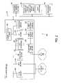
- FIG. 8is a functional block diagram which illustrates how a workflow is invoked in response to an event in an workflow server of the present invention.
- the workflowsare grouped into sets referred to as “event rule sets”. This grouping can be accomplished by the workflow administrator via an administrative client.
- Each setincludes workflows bound to certain events.
- a conditional expressionis used to select a workflow for execution from the set of workflows associated with the event.
- a conditional expressionmay include event parameters, constants, system defined constants/variables and functions. Details for event rule sets are stored in the file system/database.
- the workflow server engineOn startup, or upon receiving instructions from the workflow administrator, the workflow server engine reads one or more event rule sets and all the workflows associated with the event rule sets into its internal data structures from the database server. As shown in FIG. 8 , at step 810 , an event rule set triggers one or more workflows when an event notification is received from the event handling subsystem. FIG. 8 shows multiple event rule sets 812 which allows an event to be handled in various modes. For example, in the example of a transaction processing system, multiple event rule sets allows holiday, emergency, and other modes of operation in response to an event. At step 814 , the workflow server engine locates and executes a workflow 816 associated to the event by an event rule using a conditional expression as described above. FIG.
- FIG. 8also shows a list of event definitions 818 which are used to initialize workflow parameters at step 820 .
- the workflow 816 shown in FIG. 8is merely one example of one possible workflow that may be invoked and that any other desired workflow may also be invoked by various events.
- Executing the workflow 816means traversing the workflow directed graph 822 starting from the Start step and stopping upon encountering the “Finish” step.
- the workflow initiationcreates one or more tasks, such as task 826 .
- the path from one step to anotheris determined by the result of executing the step.
- an execution routinefor example, a known method called “Execute” associated with the step is called and the path to a next step is determined form the result of the execution.
- the Execute method for a stepcan be a COM method, a DLL function call or function invocation in an EXE using Inter Process Communications (IPC) mechanisms.
- IPCInter Process Communications
- FIG. 9is a block diagram illustrating how the workflow server engine executes a step implemented using ActiveX controls technology.
- the workflow server engineis implemented using standards-based, extensible components.
- FIG. 9shows a workflow server engine 910 and a step 912 .
- the workflow server engine 910is implemented as an ActiveX control container and the step 912 is implemented as ActiveX controls with an additional interface 914 (labeled in FIG. 9 as “IStep”) and with at least one method (such as “Execute” mentioned above). Note that there may be other methods in the interface to support the editor and other tools.
- the step 912may include many other interfaces in addition to those shown in FIG. 9 .
- One feature of the inventionis that the invention allows the exchange of events and parameters with other systems (e.g., an application, an agent desktop, a host system, a mainframe, etc.) during a workflow execution.
- Thiscan be used for server-side scripting of agent desktop rules.
- the execution logicsupports different types of event models. This allows different types of events to be handled in different ways. In one embodiment, four types of events are supported including synchronous events, asynchronous events, unsolicited events, and initial events that trigger workflows. According to the nature of the exchange, a workflow developer can choose the optimal event type.
- the first event type mentioned aboveis a synchronous event.
- the workflow enginesends an event to other systems and will wait for the response to come back from the other system before it continues the execution of the workflow. For example, an exchange with a database system usually falls into this category.
- the workflow server engineWhile waiting for a response from the other system, the workflow server engine will continue to process other workflows.
- the workflow server enginealso releases the worker thread that was processing the workflow task. This reduces the number of threads required in the thread pool and reduces thread context switching overhead.
- the workflow taskis requeued to re-acquire a worker thread. This is an important optimization for a highly responsive system. Sometimes, there may be no response or users want to ignore the response from the other system. In this case, after sending the event, the engine will continue the execution of the workflow.
- the second event type mentioned aboveis an asynchronous event.
- the workflow enginesends an event to other system, and continues the execution of the same workflow.
- executionwill be redirected to the handler of the event.
- the workflow enginecan play prompts to the user while waiting for an available agent.
- the workflowwill stop playing prompt and connect the call to the available agent.
- the third event type mentioned aboveis an unsolicited event.
- eventsdo not come in a coordinated fashion. For example, a third party system may become unavailable and will therefore fail to respond or provide the proper event information.
- a hang-up during a callan example of an unsolicited event.
- the workflow enginepasses them to the workflows that are currently being executed. The engine will provide the interface for event notification.
- Other components that are interested in unsolicited eventscan also make use of that interface.
- the interfaceallows other components to notify the engine when an unsolicited event is received, check if an event is available, and retrieve unsolicited events.
- the user interfacealso allows users to specify the following: to ignore a response (send and continue); where to store the responses; and timeout values.
- the fourth event type mentioned aboveis initial events that trigger workflows. This type of event is one that is processed by an event rule and that initially causes a workflow to be invoked.
- the same message delivery API described aboveis used to send and receive messages.
- the workflow engineis the event source while the other system is the receiver.
- the eventsare generated and delivered to the engine through an internal messaging subsystem that is part of the engine implementation.
- Another benefit of the present inventionrelates the ability to add new services in a manner similar to that of new events described above.
- the inventionalso provides the ability to communicate with the new services without changing or recompiling the core workflow server engine. This allows for the delivery and extension of multi-tier solutions that are coordinated by a central workflow server engine. This allows support for external database connectivity and support for other services, for example. In addition, the overhead of adding a new service is extremely low. Examples of services that can be added include external database access, repository services, telephony services, Web server request services, email services, etc. Through a high performance messaging utility (described below), services being added can communicate effectively with the rest of the system, including the workflow engine.
- a configuration managerwill start services according to the configurations stored in a configuration registry in the database.
- Each servicehas it own entry in the configuration registry which is created during deployment.
- the servicesimplement an interface that allows the configuration manager to start, to stop and to query the identity of the service.
- the engineassumes no other knowledge about the services.
- the loading of servicesis accomplished through dynamic DLL loading which is part of WIN32 API.
- the present inventionuses a communications mechanism for integration with the rest of the workflow system.
- Servicesare integrated into the rest of the workflow system by communicating with the rest of the system through message passing. Services can communicate with other services, with the workflows in execution and with the engine.
- a lightweight messaging utility(described below) is available for this purpose.
- One advantage of this method of message passingis that sender and receiver do not have to bind to any kind of interface. In other words, the sender and receiver do not have to know about each other during compile time.
- the present inventionuses a light weight messaging utility to provide a way to communication between services.
- the messaging utilityprovides a high performance in-memory mechanism for providing communication between various parts of the system.
- the messaging utilitysupports both synchronous and asynchronous types of message passing.
- the receiving endregisters call back functions with the messaging utility. When the message becomes available, the call back functions are triggered and the message is passed through the function call.
- the asynchronous modethe messages are put into message queues for the receiver to retrieve.
- Another benefit of the present inventionis that it can facilitate real-time management and analysis by tracking and displaying statistical information.
- the execution of workflowsis instrumented to collect step execution information.
- the collected statisticsmay be made available through an RPC interface.
- the workflow and consolidation periodshould be specified through this interface.
- This featurefacilitates monitoring, performance tuning, problem identification, debugging of workflows, and diagnostics in a workflow system.
- a wide variety of informationcan be tracked and displayed including workflow execution time, the elapsed time for workflow, step execution time, the number of time a branch is taken, the number of errors which occur in a step, the number of exception occurred, etc.
- the present inventionallows other desired information to be tracked and/or displayed as well. This information can be tracked and/or displayed during specialized modes of operation (e.g., debugging), as well as during actual use of the workflow.
- the statisticsare stored during each step execution of the workflow. If desired, statistics can be consolidated at predefined intervals. A user or system administrator may choose the consolidation periods. In one embodiment, users may configure the system to collect statistics for each workflow at the following intervals: every 5 minutes during the current hour, each hour during the current day, each day during the current week, each week during the current month, etc. As can be seen, statistics may be collected in any manner desired by a user.
- a consolidation checkoccurs at an interval equal to the greatest common factor of all the intervals (e.g., if consolidation intervals are 5 minutes, 1 hour, 1 week, then consolidation occurs every 5 minutes).
- the enginekeeps track of whether new statistics have been added since the last consolidation. If no new data is available, no update is necessary for the current interval.
- minimized copyingis accomplished by using indexing on a circular buffer.
- a high-resolution timerbased on a Windows NT performance counter may be used. In this way, time resolution in the nano-second range can be achieved with minimal CPU usage.
- this feature of the present inventionmay be used to support debugging of workflows.
- Debugging supportmay include setting break points or step-by-step debugging with information being displayed for each step.
- the execution contextis always available to a user.
- the execution contextcontains information such as the parameter values, the variable values, etc. which are used in the workflow.
- a debugging programis used to control the execution of the workflow during a debugging function.
- the debugging programcontrols the execution of the workflow through an RPC interface and displays the workflow and the execution context during a debugging session.
- the debugging programsends an OpenDebug( ) RPC command to the workflow engine.
- the workflow enginethen returns an identifier for the debugging session.
- the workflow enginealso provides the entry point of the workflow to the debugging program so that it can display information accordingly.
- the present inventionallows multiple debug sessions to co-exist in the workflow engine in order to provide flexibility to a user.
- the workflow engineWhen a workflow is executed in a debug mode, the workflow engine will suspend its execution after each step. This allows a user to analyze the executed step and view the context information of the step.
- the debugging programcan query the workflow engine for the execution context, which contains a snapshot of the contents of the variables during the current step. The execution process will resume when the debugging program sends a Step command to the workflow engine. If desired, the debugging program can alter the content of any variables in the execution context.
- the debugging programcan terminate the session by issuing a CloseDebug command.
- the debugging programcan also re-start the session using the same workflow. This saves the overhead of opening a new debugging session. If desired, statistical information may be used together with debugging information for diagnostic purposes.
- FIG. 10is a block diagram showing a workflow server engine 1002 , a workflow editor 1008 , and an overlay data provider 1020 .
- the function of the workflow server engine 1002is to execute the workflow and gather runtime statistical data relating to each of the workflows currently being executed.
- the overlay data provider 1020is connected between the workflow server engine 1002 and the workflow editor 1008 and functions to extract the runtime statistical information for the required workflow from the workflow server engine 1002 and to provide the information to the workflow editor 1008 .
- the workflow editor 1008displays the workflow and the statistical information.
- An exemplary process for displaying workflow statisticsis shown in FIG. 10 and described below.
- the first step in the process of displaying workflow statisticsis for the workflow editor 1008 to specify the workflow for which information is to be displayed.
- the workflow server engine 1002extracts runtime statistics for the specified workflow(s) and sends the information to the overlay data provider 1020 .
- the overlay data provider 1020computes statistics on per step, per branch, and/or on an overall workflow basis for display on the editor 1008 .
- the workflow editor 1008exposes an overlay interface that can be used by clients (such as the overlay data provider 1020 ) to display overlay data on the workflow.
- clientssuch as the overlay data provider 1020
- the editor 1008does not try to interpret the data, but rather just displays the data at the location specified on the workflow. More details about the workflow server engine and overlay data provider is provided below.
- FIGS. 11 and 12are sample diagrams of an exemplary workflow illustrating the overlay of statistical data onto a workflow diagram.
- FIG. 11shows the display of a workflow diagram with no statistical information overlaid. Note that the workflow shown in FIG. 11 is used as an example and that the invention may be applied to various types of displays.
- FIG. 12shows the same workflow diagram with statistical information overlaid on the display. The example shown in FIG. 12 demonstrates a sample overlay for the execution count for each step in the workflow. The overlaid information indicates the number of times each step was executed, as well as the percentage of times the workflow followed each branch. For example, the “START” and “FINISH” steps show counts of “7” and that these steps were executed 100% of the time.
- the first step, labeled “If 1 ”is shown as being executed 7 times, also 100% of the time.
- the step “SetVariable 1 ”was executed 4 times and 57.1% of the time (4 out of 7 times).
- the step labeled “Case 1 ”was executed 3 times and 42.9% of the time.
- the overlay data providedcan be absolute values or percentage values.
- the overlaid information shown in FIG. 12also shows the counts for each output connection point of each step. For example, for the step “If 1 ”, the output connection “TRUE” was executed 4 times while the output connection “False” was executed 3 times. Note that these numbers correspond to the number of times each branch of the workflow is executed. For the step “Case 1 ”, of 4 times this branch was executed, the output “Tag 0 ” was executed 1 time and the output “Default” was executed 2 times. The output connections “Tag 1 ” and “Tag 2 ” were not executed in this example.
- the informationcan also be displayed in other ways.
- different color schemesmay be used to highlight different bounds or ranges of overlay data.
- the Editormaintains specifications for highlighting the overlay data with different colors, so that abnormally large/low values or other data ranges can be visually flagged in different ways.
- the Editorinterprets the data provided on its overlay interface only to figure out what data range they fall in and decide about the color to be used to display the overlay data.
- red text or backgroundmay be used to show the steps executed >50% of the time, blue for the steps executed less than 50%, but greater than 20% of the time, yellow for the steps executed less than 20% of the time, and black for steps that are not executed.
- red text or backgroundmay be used to show the steps executed >50% of the time, blue for the steps executed less than 50%, but greater than 20% of the time, yellow for the steps executed less than 20% of the time, and black for steps that are not executed.
- red text or backgroundmay be used to show the steps executed >50% of the time, blue for the steps executed less than 50%,
- the statistical informationmay be selectively displayed through the use of a pointing device such as a mouse.
- a pointing devicesuch as a mouse.
- the inventionallows a user to position a pointer over any step in the workflow. After a predetermined amount of time (e.g., 1 second), a window appears near the pointer displaying the relevant information. For example, if a workflow is displayed such as that shown in FIG. 11 , and the user positioned the pointer over the “START” step, the window would appear and show “7–100.0%”, or whatever other information it is designed to display. In another example, where information is already overlaid, positioning the pointer will cause more detailed information to be displayed.
- the workflow server enginecollects and stores data about the execution of the workflow as well as different steps in the workflow.
- the workflow server engineexposes an RPC interface for querying the data for a workflow.
- Clientse.g., overlay data providers
- the workflow server enginecan record a variety of step-by-step metrics as a workflow is executed. In addition to the step metrics, it can record a variety of workflow level metrics as well.
- a list of sample metrics which may be used by the workflow server engine to record statistical datais shown in Table 1 below.
- the overlay data provideris capable of extracting the statistical data, and based on the metrics shown above from the workflow server engine, perform the required calculations and modifications on the data in order to provide the desired data to the editor using the overlay interface.
- the above mentioned overlay componentsshield the dependencies from each other.
- the overlay data provideris the only component that uses the other two components directly. So, it is possible to add different data providers querying different workflow server engines, or manipulating the overlay data from the workflow server engine in different ways and then using the editor to display the overlay.
- the statistical informationmay be displayed in places other than the workflow editor.
- any device on the networkmay display information.
- a system administrator's machine or an agent desktopmay display the information described above.
- the informationmay be displayed in a way other than an overlay. for example, the information may be displayed in a table format.
- FIG. 13is a diagram illustrating an example where four workflow server engines 1302 share a common configuration database server 1304 .
- all of the required configuration information needed to start the workflow server engines 1302 and to execute workflowsi.e., all the information required to execute the steps in workflows
- the database server 1304is used for storing workflow server engine initialization parameters, workflows, event-to-workflow rule sets, parameters of resources used by the steps during initialization and execution, etc.
- the use of one single enterprise wide configuration databasemakes it easier to administer the workflow systems and also makes it easier to present a single unified view of the system.
- the enterprisemay have one or more workflow server engines working off the same configuration database. This allows distribution of load to multiple workflow server engines making it easier to scale up in the case of higher event processing needs.
- Each workflow server engineis configured to load event rule sets appropriate to process events from event sources attached to that workflow server engine.
- One advantage of a centralized database such as the database server 1304 shown in FIG. 13is that when a user wants to make a change to the configuration of all of the workflow server engines 1302 , that change can be made once to the database server 1304 . For example, if a user modifies a workflow that is to be used by all of the workflow server engines 1302 , the user can make the necessary modifications at the database server 1304 and the changes will be effective for all of the workflow server engines 1302 . In the prior art, the changes had to be made separately at the database servers for each of the workflow server engines.
- the inventionprovides a locking mechanism for preventing concurrency control problems. Without this mechanism, it would be possible to make a change to a configuration in the database server 1304 , but if a workflow server engine 1302 had already loaded the changed workflow, the loaded workflow would not have the changes.
- the inventionprovides a locking mechanism that prevents changes to the database configuration when the components to be changed are in use by one or more of the workflow server engines 1302 . In other words, changes to components of the database server 1304 are only allowed when none of the workflow server engines 1302 have that component loaded. In addition, the workflow server engines 1302 are not allowed to load a component while it is being modified.
- the inventionallows some components to be locked down by this mechanisms, while others are allowed to be updated while in use by one or more of the workflow server engines 1302 . For example, workflows and rule sets may be chosen to be locked down, while general database access may be allowed.
- Another benefit of the present inventionis that it facilitates the incremental loading and unloading of workflows and rules.
- the behavior of an workflow server enginedepends on the workflows and rules (event rule sets) which are currently loaded. In the prior art, either all or none of the workflows and rules may be loaded.
- the inventionallows applications to be partitioned so that they can be selectively loaded without affecting other applications.
- the workflow server enginesupports dynamic loading and unloading of event-to-workflow rule sets using the workflow administrator. This allows the user of the system to create multiple rule sets to meet the needs of a dynamic business environment. The user may create sets for handling events during very high load or during an unexpected situation. There may be sets for handling events during a holiday or for the situation arising out of the introduction of new products and/or services.
- the workflow server enginemaintains a sorted list of currently loaded event-to-workflow rule sets. The latest loaded set is at the top of the list and the earliest loaded set is at the bottom of the list.
- the enginesearches this list from the top for a list of all the workflows bound to that event. The engine proceeds to the next set if no match is found. Otherwise, the conditional expression attached to the first event-to-workflow rule is evaluated.
- the workflow server enginestarts executing the bound workflow if the evaluated condition evaluates to true, otherwise the conditional expression attached to the next rule is evaluated, etc.
- the workflow server engineproceeds to the next set if the conditional expressions attached to all the rules for a given event in a given set evaluate to false.
- the workflow server engineallows one or more sets from the list of loaded sets to be unloaded.
- the unloadingmay not happen immediately as there may be workflows from the set executing at the time of receiving the instruction.
- the workflow server enginekeeps track of the sets to be unloaded and does not execute workflows from such sets.
- the workflow server engineremoves the sets marked for unloading from its internal data structures once all the workflows in the set finish executing.
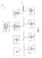
- FIG. 14is a block diagram illustrating the loading and unloading of workflow rule sets.
- FIG. 14shows a plurality of event rules sets.
- An event rule setconsists of one or more event rules.
- One or more administration commandsselectively load the event rules sets on the workflow server engine.
- FIG. 14illustrates that more than one event rule set may be actively loaded onto an workflow server engine. If multiple sets are loaded, the sets are searched from newest to oldest for a matching event rules (described above). A match results in a workflow being executed and a one or more tasks being performed.
- FIG. 14also illustrates that the administrator can query the workflow server engine to enumerate the loaded sets.
- a typical prior art workflow systemmay include error branches, but are very limited. For example, prior art error branches are included in the workflow in every place that an error might be expected. As a result, for many errors, a prior art workflow system just aborts the execution of the workflow.
- the present inventionutilizes an exception handling system which is analogous to some programming languages (e.g., the “on error goto X” command in Visual Basic).
- the exception handling system of the present inventionsupports defining exceptions, raising exceptions and handling exceptions at multiple levels (described below).
- the workflow server enginechecks for exceptions after each step and handles any exceptions accordingly.
- exceptionsare stored as part of the workflow system configuration so that they are accessible to workflow designs. New definitions can be added to the configuration and used by any components. Following are examples of exceptions that can be handled: database access failures, failure to connect to other services, invalid expressions, etc.
- Any steps or services within the workflow systemcan raise an exception through an API exposed by the workflow engine.
- the APIrequires the caller to specify the type of exception, and an optional reason code.
- a raised exceptionis placed in a queue and when the current step is done, the workflow server engine will pick up the exception and handle it according to the type of handling specified for that exception.
- the usercan specify how each exception will be handled by declaring exception handlers.
- the declarationis accomplished through an OnException step. On this step, users can indicate to ignore an exception, jump to a handler, or end the current workflow immediately.
- OnException stepusers can indicate to ignore an exception, jump to a handler, or end the current workflow immediately.
- the specified handling for an exceptionwill override previous a handling. So, for a particular exception raised, the declaration that is closest to the point of exception will take effect.
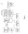
- FIG. 15is an example of a workflow diagram which handles a database exception, for example, if a database access request fails.
- the handler of an exceptionis specified in the OnExecution step (the steps that follow a goto branch of an OnException are the exception handler for the exceptions checked in the OnExecution step).
- the workflow shown in FIG. 15executes the first OnExecution step, “IgnoreDatabaseException” which specifies the workflow server engine to ignore database exceptions.
- the next step, “If 1 ”checks the value of a variable called “QueryIsCritical”. The purpose of this step is to determine whether the database access exception can be ignored, or if the database access is critical to the workflow.
- the value of this variablecould come from an event source, user input, etc.
- the second OnException step“HandleDatabaseException”, specifies that when a database exception occurs, goto step “SetVariable 1 ”. In this case, the second OnExecution step overrides the first one and if an exception really occurs in the GetRecord step, then execution will goto the SetVariable 1 step. Note that the “HandleDatabaseException” step will be executed only if “QueryIsCritical” is set to a value of “YES”.
- the exception handling technique of the present inventionprovides great flexibility to a workflow designer and reduces the number of outputs and complexity of a workflow.
- the schemeallows dynamic exception handling during runtime.
- the inventionalso supports multiple levels. For example, during an exception branch, another exception may occur, which may be handled by another exception branch.
- a list of exceptionsmay be listed in the database and a workflow designer can pick any of these and selectively decide how the handle them or whether to ignore them.
Landscapes
- Engineering & Computer Science (AREA)
- Business, Economics & Management (AREA)
- Human Resources & Organizations (AREA)
- Strategic Management (AREA)
- Economics (AREA)
- Entrepreneurship & Innovation (AREA)
- Educational Administration (AREA)
- Game Theory and Decision Science (AREA)
- Development Economics (AREA)
- Marketing (AREA)
- Operations Research (AREA)
- Quality & Reliability (AREA)
- Tourism & Hospitality (AREA)
- Physics & Mathematics (AREA)
- General Business, Economics & Management (AREA)
- General Physics & Mathematics (AREA)
- Theoretical Computer Science (AREA)
- Management, Administration, Business Operations System, And Electronic Commerce (AREA)
Abstract
Description
- GetNextStep(pConnectPoint))
- //Execute Step, assuming a single input point to the step execute step
- get next output connect point the control flow has transferred to
- signal error
| TABLE 1 |
| METRIC |
| Total execution time per workflow | ||
| Number of timed executions per workflow | ||
| Maximum execution time per workflow | ||
| Number of executions per workflow | ||
| Total execution time per step | ||
| Number of timed executions per step | ||
| Maximum execution time per step | ||
| Maximum execution time of slowest step | ||
| Step with slowest execution per workflow. | ||
| Number of executions per step | ||
| Number of executions per step output branch | ||
| Number of events per event type | ||
| Number of no binding events per event type | ||
| Num. Exceptions/alarms per step | ||
| Num. Exceptions/alarms per output branch | ||
| Total number of events | ||
| Total number of workflow executions | ||
| Maximum number of tasks (high-water mark) | ||
| Total time number of tasks over licensed limit | ||
Claims (17)
Priority Applications (2)
| Application Number | Priority Date | Filing Date | Title |
|---|---|---|---|
| US09/557,264US7221377B1 (en) | 2000-04-24 | 2000-04-24 | Apparatus and method for collecting and displaying information in a workflow system |
| US11/012,391US7535479B2 (en) | 2000-04-24 | 2004-12-14 | Apparatus and method for collecting and displaying information in a workflow system |
Applications Claiming Priority (1)
| Application Number | Priority Date | Filing Date | Title |
|---|---|---|---|
| US09/557,264US7221377B1 (en) | 2000-04-24 | 2000-04-24 | Apparatus and method for collecting and displaying information in a workflow system |
Related Child Applications (1)
| Application Number | Title | Priority Date | Filing Date |
|---|---|---|---|
| US11/012,391ContinuationUS7535479B2 (en) | 2000-04-24 | 2004-12-14 | Apparatus and method for collecting and displaying information in a workflow system |
Publications (1)
| Publication Number | Publication Date |
|---|---|
| US7221377B1true US7221377B1 (en) | 2007-05-22 |
Family
ID=34549633
Family Applications (2)
| Application Number | Title | Priority Date | Filing Date |
|---|---|---|---|
| US09/557,264Expired - LifetimeUS7221377B1 (en) | 2000-04-24 | 2000-04-24 | Apparatus and method for collecting and displaying information in a workflow system |
| US11/012,391Expired - LifetimeUS7535479B2 (en) | 2000-04-24 | 2004-12-14 | Apparatus and method for collecting and displaying information in a workflow system |
Family Applications After (1)
| Application Number | Title | Priority Date | Filing Date |
|---|---|---|---|
| US11/012,391Expired - LifetimeUS7535479B2 (en) | 2000-04-24 | 2004-12-14 | Apparatus and method for collecting and displaying information in a workflow system |
Country Status (1)
| Country | Link |
|---|---|
| US (2) | US7221377B1 (en) |
Cited By (48)
| Publication number | Priority date | Publication date | Assignee | Title |
|---|---|---|---|---|
| US20050015293A1 (en)* | 2003-07-16 | 2005-01-20 | International Business Machines Corporation | Collaboration enhanced workflow system |
| US20050120352A1 (en)* | 2003-11-28 | 2005-06-02 | Sun Microsystems, Inc. | Meta directory server providing users the ability to customize work-flows |
| US20060029206A1 (en)* | 2004-08-03 | 2006-02-09 | Nikolay Anisimov | Method and apparatus for integrating agent status between a customer relations management system and a multiple channel communications center |
| US20060075391A1 (en)* | 2004-10-05 | 2006-04-06 | Esmonde Laurence G Jr | Distributed scenario generation |
| US20060143591A1 (en)* | 2004-12-23 | 2006-06-29 | Microsoft Corporation | Extensibility framework for developing front office (CRM) workflow automation components |
| US20070143736A1 (en)* | 2005-12-09 | 2007-06-21 | Microsystems Technology, Inc. | Workflow Development Platform |
| US20070192153A1 (en)* | 2005-12-15 | 2007-08-16 | Fujitsu Limited | Information processing terminal and server for supporting quality improvement concerning product manufacture |
| US20080065448A1 (en)* | 2006-09-08 | 2008-03-13 | Clairvoyance Corporation | Methods and apparatus for identifying workflow graphs using an iterative analysis of empirical data |
| US20080114810A1 (en)* | 2006-11-13 | 2008-05-15 | Microsoft Corporation | Declarative data binding and data type propagation in a remote workflow schedule authoring system |
| US20080222240A1 (en)* | 1998-09-11 | 2008-09-11 | Genesys Telecommunications Laboratories, Inc. | Method and Apparatus for Extended Management of State and Interaction of a Remote Knowledge Worker from a Contact Center |
| US20080306751A1 (en)* | 2007-06-08 | 2008-12-11 | Level 3 Communications, Llc | Systems and methods for managing business processes in an enterprise |
| US20090260017A1 (en)* | 2008-04-15 | 2009-10-15 | Canon Kabushiki Kaisha | Workflow execution device and workflow execution method |
| US20090307298A1 (en)* | 2008-06-09 | 2009-12-10 | International Business Machines Corporation | Optimizing Service Processing Based on Business Information, Operational Intelligence, and Self-Learning |
| US20100058297A1 (en)* | 2008-09-02 | 2010-03-04 | Microsoft Corporation | Seamless debugging among different application views |
| US20100106657A1 (en)* | 2005-01-03 | 2010-04-29 | Cerner Innovation, Inc. | User interface for displaying an item of work in a workflow context |
| US7739325B1 (en)* | 2000-04-24 | 2010-06-15 | Aspect Software, Inc. | Apparatus and method for extensible real-time workflows |
| US7799273B2 (en) | 2004-05-06 | 2010-09-21 | Smp Logic Systems Llc | Manufacturing execution system for validation, quality and risk assessment and monitoring of pharmaceutical manufacturing processes |
| US20100325190A1 (en)* | 2009-06-23 | 2010-12-23 | Microsoft Corporation | Using distributed queues in an overlay network |
| US20100322256A1 (en)* | 2009-06-23 | 2010-12-23 | Microsoft Corporation | Using distributed timers in an overlay network |
| US20110145096A1 (en)* | 2009-12-15 | 2011-06-16 | A Big Blessed Family, Llc | Remote servicing system |
| USRE43205E1 (en) | 2003-08-27 | 2012-02-21 | Aspect Software, Inc. | Skill based chat function in a communication system |
| US20130018815A1 (en)* | 2011-07-14 | 2013-01-17 | International Business Machines Corporation | Decomposing A Process Model In An Enterprise Intelligence ('EI') Framework |
| EP2620868A1 (en)* | 2012-01-30 | 2013-07-31 | systego GmbH | Work flow management system for computer networks |
| US8971216B2 (en) | 1998-09-11 | 2015-03-03 | Alcatel Lucent | Method for routing transactions between internal and external partners in a communication center |
| US9008075B2 (en) | 2005-12-22 | 2015-04-14 | Genesys Telecommunications Laboratories, Inc. | System and methods for improving interaction routing performance |
| USRE45583E1 (en) | 1999-12-01 | 2015-06-23 | Genesys Telecommunications Laboratories, Inc. | Method and apparatus for providing enhanced communication capability for mobile devices on a virtual private network |
| USRE45606E1 (en) | 1997-02-10 | 2015-07-07 | Genesys Telecommunications Laboratories, Inc. | Call and data correspondence in a call-in center employing virtual restructuring for computer telephony integrated functionality |
| USRE46060E1 (en) | 1997-02-10 | 2016-07-05 | Genesys Telecommunications Laboratories, Inc. | In-band signaling for routing |
| USRE46153E1 (en) | 1998-09-11 | 2016-09-20 | Genesys Telecommunications Laboratories, Inc. | Method and apparatus enabling voice-based management of state and interaction of a remote knowledge worker in a contact center environment |
| US9507882B1 (en)* | 2013-08-12 | 2016-11-29 | Amazon Technologies, Inc. | Declarative language dynamic web platform |
| US9516171B2 (en) | 1997-02-10 | 2016-12-06 | Genesys Telecommunications Laboratories, Inc. | Personal desktop router |
| CN106302778A (en)* | 2016-08-25 | 2017-01-04 | 广东亿迅科技有限公司 | A kind of distributed flow process automotive engine system |
| US9553755B2 (en) | 1998-02-17 | 2017-01-24 | Genesys Telecommunications Laboratories, Inc. | Method for implementing and executing communication center routing strategies represented in extensible markup language |
| US9639815B2 (en)* | 2011-07-14 | 2017-05-02 | International Business Machines Corporation | Managing processes in an enterprise intelligence (‘EI’) assembly of an EI framework |
| US9659266B2 (en) | 2011-07-14 | 2017-05-23 | International Business Machines Corporation | Enterprise intelligence (‘EI’) management in an EI framework |
| USRE46438E1 (en) | 1999-09-24 | 2017-06-13 | Genesys Telecommunications Laboratories, Inc. | Method and apparatus for data-linking a mobile knowledge worker to home communication-center infrastructure |
| USRE46528E1 (en) | 1997-11-14 | 2017-08-29 | Genesys Telecommunications Laboratories, Inc. | Implementation of call-center outbound dialing capability at a telephony network level |
| CN109740920A (en)* | 2018-12-29 | 2019-05-10 | 江苏电力信息技术有限公司 | It is called by management and monitoring RPA robot realizes the method that operation flow automates |
| US10904087B2 (en)* | 2014-04-02 | 2021-01-26 | Aria Solutions, Inc. | Configurable cloud-based routing |
| US11086651B2 (en) | 2019-01-24 | 2021-08-10 | Salesforce.Com, Inc. | Workflow version management |
| US11107158B1 (en) | 2014-02-14 | 2021-08-31 | Experian Information Solutions, Inc. | Automatic generation of code for attributes |
| US11157872B2 (en) | 2008-06-26 | 2021-10-26 | Experian Marketing Solutions, Llc | Systems and methods for providing an integrated identifier |
| US11227001B2 (en) | 2017-01-31 | 2022-01-18 | Experian Information Solutions, Inc. | Massive scale heterogeneous data ingestion and user resolution |
| EP3944102A1 (en)* | 2020-07-22 | 2022-01-26 | Accenture Global Solutions Limited | Data processing management system and method |
| US11308170B2 (en) | 2007-03-30 | 2022-04-19 | Consumerinfo.Com, Inc. | Systems and methods for data verification |
| US11734234B1 (en) | 2018-09-07 | 2023-08-22 | Experian Information Solutions, Inc. | Data architecture for supporting multiple search models |
| US11880377B1 (en) | 2021-03-26 | 2024-01-23 | Experian Information Solutions, Inc. | Systems and methods for entity resolution |
| US11941065B1 (en) | 2019-09-13 | 2024-03-26 | Experian Information Solutions, Inc. | Single identifier platform for storing entity data |
Families Citing this family (55)
| Publication number | Priority date | Publication date | Assignee | Title |
|---|---|---|---|---|
| US7496924B2 (en)* | 2000-03-27 | 2009-02-24 | Siemens Communications, Inc. | Dispatching messages among registered software modules in telecommunications system including telephony internet server coupled between packet network and PBX |
| US8924408B2 (en)* | 2001-09-28 | 2014-12-30 | International Business Machines Corporation | Automatic generation of database invocation mechanism for external web services |
| US8914807B2 (en)* | 2001-09-28 | 2014-12-16 | International Business Machines Corporation | Method, system, and program for generating a program capable of invoking a flow of operations |
| US8166006B2 (en)* | 2001-09-28 | 2012-04-24 | International Business Machines Corporation | Invocation of web services from a database |
| US20030217053A1 (en)* | 2002-04-15 | 2003-11-20 | Bachman George E. | Context control mechanism for data executed in workflows of process, factory-floor, environmental, computer aided manufacturing-based or other control system |
| US7386528B2 (en) | 2002-05-31 | 2008-06-10 | American Express Travel Related Services Company, Inc. | System and method for acquisition, assimilation and storage of information |
| US7194744B2 (en)* | 2002-12-17 | 2007-03-20 | International Business Machines Corporation | System and method for dynamic exception handling using an external exception handler |
| US8230445B2 (en)* | 2003-01-14 | 2012-07-24 | International Business Machines Corporation | Event management method and system |
| CA2416349A1 (en)* | 2003-01-14 | 2004-07-14 | Cognos Incorporated | Dynamic recipients in an event management system |
| US20040139448A1 (en)* | 2003-01-14 | 2004-07-15 | Hope Clifford C. | Interative escalation in an event management system |
| US20040138931A1 (en)* | 2003-01-14 | 2004-07-15 | Hope Clifford C. | Trend detection in an event management system |
| US20040139446A1 (en)* | 2003-01-14 | 2004-07-15 | Hope Clifford C. | Event management system and method |
| US20040139450A1 (en)* | 2003-01-14 | 2004-07-15 | Hope Clifford C. | Contextual drill through in an event management system |
| US20040139444A1 (en)* | 2003-01-14 | 2004-07-15 | Hope Clifford C. | Notification service in an event management system |
| CA2416352A1 (en)* | 2003-01-14 | 2004-07-14 | Cognos Incorporated | Autonomous dynamic behavior modification in an event management system |
| CA2416357A1 (en)* | 2003-01-14 | 2004-07-14 | Cognos Incorporated | Message suppression in an event management system |
| JP2005285106A (en)* | 2004-03-01 | 2005-10-13 | Ricoh Co Ltd | Process management device, user terminal device, process management program, user terminal program, recording medium, process management method, and search method |
| US7929685B1 (en)* | 2004-05-27 | 2011-04-19 | Apple Inc. | Queuing calls for distribution |
| US20060010025A1 (en)* | 2004-07-09 | 2006-01-12 | Sap Aktiengesellschaft | E-mail notification support for workflows |
| US20060237239A1 (en)* | 2005-04-23 | 2006-10-26 | Daniel Bruner | Personal utility vehicle (PUV) |
| US20060288332A1 (en)* | 2005-06-21 | 2006-12-21 | Microsoft Corporation | Workflow debugger |
| US7870563B2 (en)* | 2005-12-30 | 2011-01-11 | Sap Ag | Triggering workflows based on middleware events |
| US8284423B2 (en)* | 2006-04-07 | 2012-10-09 | Ricoh Production Print Solutions LLC | Customer-configurable print workflow system |
| US20080027782A1 (en)* | 2006-04-07 | 2008-01-31 | Juliana Freire | Managing provenance of the evolutionary development of workflows |
| US8060391B2 (en) | 2006-04-07 | 2011-11-15 | The University Of Utah Research Foundation | Analogy based workflow identification |
| US7509655B2 (en)* | 2006-08-30 | 2009-03-24 | Microsoft Corporation | Integration of workflow and rules |
| US8370812B2 (en)* | 2007-04-02 | 2013-02-05 | International Business Machines Corporation | Method and system for automatically assembling processing graphs in information processing systems |
| US8166465B2 (en)* | 2007-04-02 | 2012-04-24 | International Business Machines Corporation | Method and system for composing stream processing applications according to a semantic description of a processing goal |
| US20080263453A1 (en)* | 2007-04-20 | 2008-10-23 | Vijay Kumar Aggarwal | Method and apparatus for process configuration |
| US8117233B2 (en)* | 2007-05-14 | 2012-02-14 | International Business Machines Corporation | Method and system for message-oriented semantic web service composition based on artificial intelligence planning |
| US20090113042A1 (en)* | 2007-10-31 | 2009-04-30 | International Business Machines Corporaton | Method for correlating periodically aggregated data in distributed systems |
| US8161492B2 (en)* | 2008-04-15 | 2012-04-17 | Microsoft Corporation | Continuation based runtimes in transactions |
| US8190633B2 (en)* | 2008-06-16 | 2012-05-29 | The University Of Utah Research Foundation | Enabling provenance management for pre-existing applications |
| US20090327465A1 (en)* | 2008-06-27 | 2009-12-31 | Microsoft Corporation | Distributed Configuration Orchestration for Network Client Management |
| US8201176B2 (en)* | 2008-08-06 | 2012-06-12 | International Business Machines Corporation | Detecting the starting and ending of a task when thread pooling is employed |
| US8255451B2 (en)* | 2008-09-17 | 2012-08-28 | Microsoft Corporation | Technologies for detecting erroneous resumptions in a continuation based runtime |
| US8683432B2 (en)* | 2009-03-20 | 2014-03-25 | Microsoft Corporation | Providing execution context in continuation based runtimes |
| US20100269091A1 (en)* | 2009-04-20 | 2010-10-21 | International Business Machines Corporation | Jvm exception debugging |
| US20100293538A1 (en)* | 2009-05-15 | 2010-11-18 | Microsoft Corporation | Dynamic program updating in a continuation based runtime |
| WO2011136780A1 (en)* | 2010-04-29 | 2011-11-03 | Hewlett-Packard Development Company, L.P. | Information tracking system and method |
| CA2835711A1 (en)* | 2011-05-10 | 2012-11-15 | Dante Consulting, Inc. | Enterprise product management system and method |
| US10282461B2 (en) | 2015-07-01 | 2019-05-07 | Ncino, Inc. | Structure-based entity analysis |
| US10192262B2 (en) | 2012-05-30 | 2019-01-29 | Ncino, Inc. | System for periodically updating backings for resource requests |
| US9471665B2 (en)* | 2014-08-01 | 2016-10-18 | Ncino, Inc. | Unified system for real-time coordination of content-object action items across devices |
| US10013237B2 (en) | 2012-05-30 | 2018-07-03 | Ncino, Inc. | Automated approval |
| US20140222493A1 (en)* | 2013-02-04 | 2014-08-07 | Uni-B Solutions Llc | Process management system, method, and computer-readable medium |
| CA2932897A1 (en)* | 2013-12-06 | 2015-06-11 | Biodatomics, LLC | Visual effects system for "big data" analysis workflow editors, distribution platforms, execution engines, and management systems comprising same |
| US11244264B2 (en)* | 2014-12-29 | 2022-02-08 | Hand Held Products, Inc. | Interleaving surprise activities in workflow |
| CN105897805B (en)* | 2015-01-04 | 2019-12-27 | 伊姆西公司 | Method and device for cross-layer scheduling of resources of data center with multi-layer architecture |
| US10460047B1 (en)* | 2015-02-27 | 2019-10-29 | The Mathworks, Inc. | Tentative model components |
| EP3101603A1 (en)* | 2015-06-04 | 2016-12-07 | Easy Payment Gateway Ltd | A method and apparatus for providing an electronic transaction gateway |
| US11657068B2 (en)* | 2017-12-15 | 2023-05-23 | International Business Machines Corporation | Efficient migration between asynchronous data replication technologies |
| US11790224B2 (en)* | 2018-10-20 | 2023-10-17 | Oracle International Corporation | Machine learning from the integration flow metadata |
| US11494713B2 (en)* | 2020-08-28 | 2022-11-08 | UiPath, Inc. | Robotic process automation analytics platform |
| US20240045892A1 (en)* | 2022-08-03 | 2024-02-08 | International Business Machines Corporation | Interfacing with planned operations of an aggregated assistant |
Citations (83)
| Publication number | Priority date | Publication date | Assignee | Title |
|---|---|---|---|---|
| US4328556A (en) | 1975-09-09 | 1982-05-04 | Tokyo Denryoku Kabushiki Kaisha | Control system of plants by means of electronic computers |
| US4413277A (en)* | 1981-01-23 | 1983-11-01 | Instant Replay Systems | Instant replay productivity motivation system |
| US4885694A (en) | 1987-04-29 | 1989-12-05 | Honeywell Inc. | Automated building control design system |
| US5040227A (en) | 1990-03-12 | 1991-08-13 | International Business Machines Corporation | Image balancing system and method |
| US5095221A (en) | 1989-11-03 | 1992-03-10 | Westinghouse Electric Corp. | Gas turbine control system having partial hood control |
| US5129057A (en)* | 1988-05-02 | 1992-07-07 | International Business Machines Corporation | Method for presenting compressed electronic day calendar information in an interactive information handling system |
| US5185861A (en) | 1991-08-19 | 1993-02-09 | Sequent Computer Systems, Inc. | Cache affinity scheduler |
| US5214756A (en) | 1989-03-10 | 1993-05-25 | International Business Machines Corporation | Direct manipulation of icons via conversational linking |
| US5301301A (en) | 1991-01-30 | 1994-04-05 | National Instruments Corporation | Polymorphic dataflow block diagram system and method for programming a computer |
| US5323452A (en) | 1990-12-18 | 1994-06-21 | Bell Communications Research, Inc. | Visual programming of telephone network call processing logic |
| US5367624A (en) | 1993-06-11 | 1994-11-22 | Consilium, Inc. | Interface for controlling transactions in a manufacturing execution system |
| US5404523A (en) | 1993-11-10 | 1995-04-04 | Digital Equipment Corporation | Method of managing requests in a transaction processing system |
| US5455903A (en) | 1991-05-31 | 1995-10-03 | Edify Corp. | Object oriented customer information exchange system and method |
| US5455854A (en) | 1993-10-26 | 1995-10-03 | Taligent, Inc. | Object-oriented telephony system |
| US5533110A (en) | 1994-11-29 | 1996-07-02 | Mitel Corporation | Human machine interface for telephone feature invocation |
| US5535322A (en) | 1992-10-27 | 1996-07-09 | International Business Machines Corporation | Data processing system with improved work flow system and method |
| US5555179A (en) | 1993-09-03 | 1996-09-10 | Hitachi, Ltd. | Control method and control apparatus of factory automation system |
| US5576946A (en) | 1993-09-30 | 1996-11-19 | Fluid Air, Inc. | Icon based process design and control system |
| US5586312A (en) | 1994-10-11 | 1996-12-17 | Unisys Corporation | Method and apparatus for using an independent transaction processing application as a service routine |
| US5623541A (en) | 1995-02-17 | 1997-04-22 | Lucent Technologies Inc. | Apparatus to manipulate and examine the data structure that supports digit analysis in telecommunications call processing |
| US5644728A (en) | 1995-02-14 | 1997-07-01 | Ncr Corporation | Control systems |
| US5649131A (en) | 1992-12-30 | 1997-07-15 | Lucent Technologies Inc. | Communications protocol |
| US5664129A (en) | 1994-08-10 | 1997-09-02 | Hitachi, Ltd. | Visual programming method |
| US5734837A (en) | 1994-01-14 | 1998-03-31 | Action Technologies, Inc. | Method and apparatus for building business process applications in terms of its workflows |
| US5742814A (en) | 1995-11-01 | 1998-04-21 | Imec Vzw | Background memory allocation for multi-dimensional signal processing |
| US5745763A (en) | 1995-09-29 | 1998-04-28 | International Business Machines Corporation | Method and apparatus for device driver funnelling |
| US5754636A (en) | 1994-11-01 | 1998-05-19 | Answersoft, Inc. | Computer telephone system |
| US5765033A (en) | 1997-02-06 | 1998-06-09 | Genesys Telecommunications Laboratories, Inc. | System for routing electronic mails |
| US5799297A (en) | 1995-12-15 | 1998-08-25 | Ncr Corporation | Task workflow management system and method including an external program execution feature |
| US5812989A (en) | 1993-12-29 | 1998-09-22 | International Business Machines Corporation | Image statement preparation by work flow management using statement cycles and statement interactive sessions |
| US5831611A (en) | 1995-02-24 | 1998-11-03 | Saleslogix Corporation | Apparatus and method for creating and executing graphically depicted communication |
| US5835898A (en)* | 1996-02-29 | 1998-11-10 | Dcd Corporation | Visual schedule management system for a manufacturing facility |
| US5848393A (en) | 1995-12-15 | 1998-12-08 | Ncr Corporation | "What if . . . " function for simulating operations within a task workflow management system |
| US5903730A (en)* | 1996-08-23 | 1999-05-11 | Fujitsu Limited | Method of visualizing results of performance monitoring and analysis in a parallel computing system |
| US5905493A (en) | 1996-11-13 | 1999-05-18 | Unalink Communications, Inc. | Color coded instructional scheme for computers and the like system, method and article of manufacture |
| US5918226A (en) | 1995-01-11 | 1999-06-29 | Nec Corporation | Workflow system for operating and managing jobs with predicting future progress of workflow job |
| US5926539A (en) | 1997-09-12 | 1999-07-20 | Genesys Telecommunications Laboratories, Inc. | Method and apparatus for determining agent availability based on level of uncompleted tasks |
| US5940804A (en) | 1996-12-18 | 1999-08-17 | Turley; William N. | Computer executable workflow resource management system |
| US5946387A (en) | 1997-02-10 | 1999-08-31 | Genesys Telecommunications Laboratories, Inc, | Agent-level network call routing |
| US5953332A (en) | 1997-02-10 | 1999-09-14 | Genesys Telecommunications Laboratories, Inc. | Agent-initiated dynamic requeing |
| US5953405A (en) | 1997-02-10 | 1999-09-14 | Genesys Telecommunications Laboratories, Inc. | Agent-predictive routing process in call-routing systems |
| US5999965A (en) | 1996-08-20 | 1999-12-07 | Netspeak Corporation | Automatic call distribution server for computer telephony communications |
| US5999911A (en) | 1995-06-02 | 1999-12-07 | Mentor Graphics Corporation | Method and system for managing workflow |
| US6002760A (en) | 1998-02-17 | 1999-12-14 | Genesys Telecommunications Laboratories, Inc. | Intelligent virtual queue |
| US6021428A (en) | 1997-09-15 | 2000-02-01 | Genesys Telecommunications Laboratories, Inc. | Apparatus and method in improving e-mail routing in an internet protocol network telephony call-in-center |
| US6028997A (en) | 1992-05-30 | 2000-02-22 | International Business Machines Corporation | Method of generating an implementation of reusable parts from containers of a workflow process-model |
| US6044145A (en) | 1998-01-19 | 2000-03-28 | Rockwell Semiconductor Systems, Inc. | Telecommutable platform |
| US6044368A (en) | 1998-04-30 | 2000-03-28 | Genesys Telecommunications Laboratories, Inc. | Method and apparatus for multiple agent commitment tracking and notification |
| US6052684A (en)* | 1998-03-24 | 2000-04-18 | Hewlett-Packard Company | System and method for performing consistent workflow process execution in a workflow management system |
| US6067357A (en) | 1998-03-04 | 2000-05-23 | Genesys Telecommunications Laboratories Inc. | Telephony call-center scripting by Petri Net principles and techniques |
| US6105053A (en) | 1995-06-23 | 2000-08-15 | Emc Corporation | Operating system for a non-uniform memory access multiprocessor system |
| US6108711A (en) | 1998-09-11 | 2000-08-22 | Genesys Telecommunications Laboratories, Inc. | Operating system having external media layer, workflow layer, internal media layer, and knowledge base for routing media events between transactions |
| US6138139A (en) | 1998-10-29 | 2000-10-24 | Genesys Telecommunications Laboraties, Inc. | Method and apparatus for supporting diverse interaction paths within a multimedia communication center |
| US6167395A (en) | 1998-09-11 | 2000-12-26 | Genesys Telecommunications Laboratories, Inc | Method and apparatus for creating specialized multimedia threads in a multimedia communication center |
| US6170011B1 (en) | 1998-09-11 | 2001-01-02 | Genesys Telecommunications Laboratories, Inc. | Method and apparatus for determining and initiating interaction directionality within a multimedia communication center |
| US6175564B1 (en) | 1995-10-25 | 2001-01-16 | Genesys Telecommunications Laboratories, Inc | Apparatus and methods for managing multiple internet protocol capable call centers |
| US6185292B1 (en) | 1997-02-10 | 2001-02-06 | Genesys Telecommunications Laboratories, Inc. | Skill-based real-time call routing in telephony systems |
| US6192121B1 (en) | 1997-09-19 | 2001-02-20 | Mci Communications Corporation | Telephony server application program interface API |
| US6222530B1 (en) | 1998-08-21 | 2001-04-24 | Corporate Media Partners | System and method for a master scheduler |
| US6226377B1 (en) | 1998-03-06 | 2001-05-01 | Avaya Technology Corp. | Prioritized transaction server allocation |
| US6243105B1 (en)* | 1998-11-19 | 2001-06-05 | Ncr Corporation | Drill-down method to historical data in a performance monitor using a platform independent program |
| US6243092B1 (en)* | 1997-12-02 | 2001-06-05 | Aspect Communications | Transaction flow editing tool |
| US6263359B1 (en) | 1997-05-22 | 2001-07-17 | International Business Machines Corporation | Computer resource proportional utilization and response time scheduling |
| US6279009B1 (en) | 1998-12-04 | 2001-08-21 | Impresse Corporation | Dynamic creation of workflows from deterministic models of real world processes |
| US6289369B1 (en) | 1998-08-25 | 2001-09-11 | International Business Machines Corporation | Affinity, locality, and load balancing in scheduling user program-level threads for execution by a computer system |
| US6314089B1 (en) | 1996-05-07 | 2001-11-06 | Inventions, Inc. | Creating and using an adaptable multiple-contact transaction object |
| US6351778B1 (en) | 1993-07-19 | 2002-02-26 | Object Technology Licensing Corporation | Object-oriented operating system |
| US6389007B1 (en) | 1998-09-24 | 2002-05-14 | Genesys Telecommunications Laboratories, Inc. | Method and apparatus for providing integrated routing for PSTN and IPNT calls in a call center |
| US6393015B1 (en) | 1997-09-12 | 2002-05-21 | Genesys Telecommunications Laboratories, Inc. | Method and apparatus for automatic network connection between a small business and a client |
| US20020065752A1 (en)* | 1999-02-16 | 2002-05-30 | Charles J. Lewis | Financial consolidation and communication platform |
| US6411982B2 (en) | 1998-05-28 | 2002-06-25 | Hewlett-Packard Company | Thread based governor for time scheduled process execution |
| US6418458B1 (en) | 1998-10-02 | 2002-07-09 | Ncr Corporation | Object-oriented prioritized work thread pool |
| US6434435B1 (en)* | 1997-02-21 | 2002-08-13 | Baker Hughes Incorporated | Application of adaptive object-oriented optimization software to an automatic optimization oilfield hydrocarbon production management system |
| US6434590B1 (en) | 1995-07-14 | 2002-08-13 | Avaya Technology Corp. | Methods and apparatus for scheduling parallel processors |
| US6442620B1 (en) | 1998-08-17 | 2002-08-27 | Microsoft Corporation | Environment extensibility and automatic services for component applications using contexts, policies and activators |
| US20020156814A1 (en)* | 1997-01-13 | 2002-10-24 | Ho Bruce K. | Method and apparatus for visual business computing |
| US20030115545A1 (en)* | 1999-02-19 | 2003-06-19 | Lucent Technologies Inc. | Dynamic display of data item evaluation |
| US6658447B2 (en) | 1997-07-08 | 2003-12-02 | Intel Corporation | Priority based simultaneous multi-threading |
| US6704410B1 (en)* | 1998-06-03 | 2004-03-09 | Avaya Inc. | System for automatically assigning skill levels to multiple skilled agents in call center agent assignment applications |
| US6721778B1 (en) | 1994-06-01 | 2004-04-13 | Concerto Services, Inc. | Unscheduled event task processing system |
| US6732156B2 (en) | 1997-02-06 | 2004-05-04 | Genesys Telecommunications Laboratories, Inc. | System for routing electronic mails |
| US6748555B1 (en) | 1999-09-09 | 2004-06-08 | Microsoft Corporation | Object-based software management |
| US6829770B1 (en) | 1999-02-23 | 2004-12-07 | Microsoft Corporation | Object connectivity through loosely coupled publish and subscribe events |
Family Cites Families (5)
| Publication number | Priority date | Publication date | Assignee | Title |
|---|---|---|---|---|
| JP3513236B2 (en)* | 1993-11-19 | 2004-03-31 | キヤノン株式会社 | X-ray mask structure, method for manufacturing X-ray mask structure, X-ray exposure apparatus and X-ray exposure method using the X-ray mask structure, and semiconductor device manufactured using the X-ray exposure method |
| WO1997012311A2 (en)* | 1995-09-15 | 1997-04-03 | Cable & Wireless, Inc. | System and method for quality management |
| US5832611A (en)* | 1996-08-07 | 1998-11-10 | Schmitz; Jeffrey F. | Variable angle reciprocating tool |
| US6025843A (en)* | 1996-09-06 | 2000-02-15 | Peter Sklar | Clustering user interface |
| US7065493B1 (en)* | 2000-04-06 | 2006-06-20 | International Business Machines Corporation | Workflow system and method |
- 2000
- 2000-04-24USUS09/557,264patent/US7221377B1/ennot_activeExpired - Lifetime
- 2004
- 2004-12-14USUS11/012,391patent/US7535479B2/ennot_activeExpired - Lifetime
Patent Citations (86)
| Publication number | Priority date | Publication date | Assignee | Title |
|---|---|---|---|---|
| US4328556A (en) | 1975-09-09 | 1982-05-04 | Tokyo Denryoku Kabushiki Kaisha | Control system of plants by means of electronic computers |
| US4413277A (en)* | 1981-01-23 | 1983-11-01 | Instant Replay Systems | Instant replay productivity motivation system |
| US4885694A (en) | 1987-04-29 | 1989-12-05 | Honeywell Inc. | Automated building control design system |
| US5129057A (en)* | 1988-05-02 | 1992-07-07 | International Business Machines Corporation | Method for presenting compressed electronic day calendar information in an interactive information handling system |
| US5214756A (en) | 1989-03-10 | 1993-05-25 | International Business Machines Corporation | Direct manipulation of icons via conversational linking |
| US5095221A (en) | 1989-11-03 | 1992-03-10 | Westinghouse Electric Corp. | Gas turbine control system having partial hood control |
| US5040227A (en) | 1990-03-12 | 1991-08-13 | International Business Machines Corporation | Image balancing system and method |
| US5323452A (en) | 1990-12-18 | 1994-06-21 | Bell Communications Research, Inc. | Visual programming of telephone network call processing logic |
| US5301301A (en) | 1991-01-30 | 1994-04-05 | National Instruments Corporation | Polymorphic dataflow block diagram system and method for programming a computer |
| US5455903A (en) | 1991-05-31 | 1995-10-03 | Edify Corp. | Object oriented customer information exchange system and method |
| US5185861A (en) | 1991-08-19 | 1993-02-09 | Sequent Computer Systems, Inc. | Cache affinity scheduler |
| US6028997A (en) | 1992-05-30 | 2000-02-22 | International Business Machines Corporation | Method of generating an implementation of reusable parts from containers of a workflow process-model |
| US5535322A (en) | 1992-10-27 | 1996-07-09 | International Business Machines Corporation | Data processing system with improved work flow system and method |
| US5649131A (en) | 1992-12-30 | 1997-07-15 | Lucent Technologies Inc. | Communications protocol |
| US5367624A (en) | 1993-06-11 | 1994-11-22 | Consilium, Inc. | Interface for controlling transactions in a manufacturing execution system |
| US6351778B1 (en) | 1993-07-19 | 2002-02-26 | Object Technology Licensing Corporation | Object-oriented operating system |
| US5555179A (en) | 1993-09-03 | 1996-09-10 | Hitachi, Ltd. | Control method and control apparatus of factory automation system |
| US5576946A (en) | 1993-09-30 | 1996-11-19 | Fluid Air, Inc. | Icon based process design and control system |
| US5455854A (en) | 1993-10-26 | 1995-10-03 | Taligent, Inc. | Object-oriented telephony system |
| US5404523A (en) | 1993-11-10 | 1995-04-04 | Digital Equipment Corporation | Method of managing requests in a transaction processing system |
| US5812989A (en) | 1993-12-29 | 1998-09-22 | International Business Machines Corporation | Image statement preparation by work flow management using statement cycles and statement interactive sessions |
| US5734837A (en) | 1994-01-14 | 1998-03-31 | Action Technologies, Inc. | Method and apparatus for building business process applications in terms of its workflows |
| US6721778B1 (en) | 1994-06-01 | 2004-04-13 | Concerto Services, Inc. | Unscheduled event task processing system |
| US5664129A (en) | 1994-08-10 | 1997-09-02 | Hitachi, Ltd. | Visual programming method |
| US5586312A (en) | 1994-10-11 | 1996-12-17 | Unisys Corporation | Method and apparatus for using an independent transaction processing application as a service routine |
| US5754636A (en) | 1994-11-01 | 1998-05-19 | Answersoft, Inc. | Computer telephone system |
| US5533110A (en) | 1994-11-29 | 1996-07-02 | Mitel Corporation | Human machine interface for telephone feature invocation |
| US5918226A (en) | 1995-01-11 | 1999-06-29 | Nec Corporation | Workflow system for operating and managing jobs with predicting future progress of workflow job |
| US5644728A (en) | 1995-02-14 | 1997-07-01 | Ncr Corporation | Control systems |
| US5623541A (en) | 1995-02-17 | 1997-04-22 | Lucent Technologies Inc. | Apparatus to manipulate and examine the data structure that supports digit analysis in telecommunications call processing |
| US5831611A (en) | 1995-02-24 | 1998-11-03 | Saleslogix Corporation | Apparatus and method for creating and executing graphically depicted communication |
| US5999911A (en) | 1995-06-02 | 1999-12-07 | Mentor Graphics Corporation | Method and system for managing workflow |
| US6105053A (en) | 1995-06-23 | 2000-08-15 | Emc Corporation | Operating system for a non-uniform memory access multiprocessor system |
| US6434590B1 (en) | 1995-07-14 | 2002-08-13 | Avaya Technology Corp. | Methods and apparatus for scheduling parallel processors |
| US5745763A (en) | 1995-09-29 | 1998-04-28 | International Business Machines Corporation | Method and apparatus for device driver funnelling |
| US6175564B1 (en) | 1995-10-25 | 2001-01-16 | Genesys Telecommunications Laboratories, Inc | Apparatus and methods for managing multiple internet protocol capable call centers |
| US5742814A (en) | 1995-11-01 | 1998-04-21 | Imec Vzw | Background memory allocation for multi-dimensional signal processing |
| US5799297A (en) | 1995-12-15 | 1998-08-25 | Ncr Corporation | Task workflow management system and method including an external program execution feature |
| US5848393A (en) | 1995-12-15 | 1998-12-08 | Ncr Corporation | "What if . . . " function for simulating operations within a task workflow management system |
| US5835898A (en)* | 1996-02-29 | 1998-11-10 | Dcd Corporation | Visual schedule management system for a manufacturing facility |
| US6314089B1 (en) | 1996-05-07 | 2001-11-06 | Inventions, Inc. | Creating and using an adaptable multiple-contact transaction object |
| US5999965A (en) | 1996-08-20 | 1999-12-07 | Netspeak Corporation | Automatic call distribution server for computer telephony communications |
| US5903730A (en)* | 1996-08-23 | 1999-05-11 | Fujitsu Limited | Method of visualizing results of performance monitoring and analysis in a parallel computing system |
| US5905493A (en) | 1996-11-13 | 1999-05-18 | Unalink Communications, Inc. | Color coded instructional scheme for computers and the like system, method and article of manufacture |
| US5940804A (en) | 1996-12-18 | 1999-08-17 | Turley; William N. | Computer executable workflow resource management system |
| US20020156814A1 (en)* | 1997-01-13 | 2002-10-24 | Ho Bruce K. | Method and apparatus for visual business computing |
| US6732156B2 (en) | 1997-02-06 | 2004-05-04 | Genesys Telecommunications Laboratories, Inc. | System for routing electronic mails |
| US5765033A (en) | 1997-02-06 | 1998-06-09 | Genesys Telecommunications Laboratories, Inc. | System for routing electronic mails |
| US5953332A (en) | 1997-02-10 | 1999-09-14 | Genesys Telecommunications Laboratories, Inc. | Agent-initiated dynamic requeing |
| US6185292B1 (en) | 1997-02-10 | 2001-02-06 | Genesys Telecommunications Laboratories, Inc. | Skill-based real-time call routing in telephony systems |
| US6175563B1 (en) | 1997-02-10 | 2001-01-16 | Genesys Telecommunications Laboratories, Inc. | Parallel data transfer and synchronization in computer-simulated telephony |
| US5946387A (en) | 1997-02-10 | 1999-08-31 | Genesys Telecommunications Laboratories, Inc, | Agent-level network call routing |
| US5953405A (en) | 1997-02-10 | 1999-09-14 | Genesys Telecommunications Laboratories, Inc. | Agent-predictive routing process in call-routing systems |
| US6434435B1 (en)* | 1997-02-21 | 2002-08-13 | Baker Hughes Incorporated | Application of adaptive object-oriented optimization software to an automatic optimization oilfield hydrocarbon production management system |
| US6263359B1 (en) | 1997-05-22 | 2001-07-17 | International Business Machines Corporation | Computer resource proportional utilization and response time scheduling |
| US6658447B2 (en) | 1997-07-08 | 2003-12-02 | Intel Corporation | Priority based simultaneous multi-threading |
| US5926539A (en) | 1997-09-12 | 1999-07-20 | Genesys Telecommunications Laboratories, Inc. | Method and apparatus for determining agent availability based on level of uncompleted tasks |
| US6393015B1 (en) | 1997-09-12 | 2002-05-21 | Genesys Telecommunications Laboratories, Inc. | Method and apparatus for automatic network connection between a small business and a client |
| US6373836B1 (en) | 1997-09-15 | 2002-04-16 | Genesys Telecommunications Laboratories, Inc. | Apparatus and methods in routing internet protocol network telephony calls in a centrally-managed call center system |
| US6021428A (en) | 1997-09-15 | 2000-02-01 | Genesys Telecommunications Laboratories, Inc. | Apparatus and method in improving e-mail routing in an internet protocol network telephony call-in-center |
| US6192121B1 (en) | 1997-09-19 | 2001-02-20 | Mci Communications Corporation | Telephony server application program interface API |
| US6243092B1 (en)* | 1997-12-02 | 2001-06-05 | Aspect Communications | Transaction flow editing tool |
| US6044145A (en) | 1998-01-19 | 2000-03-28 | Rockwell Semiconductor Systems, Inc. | Telecommutable platform |
| US6002760A (en) | 1998-02-17 | 1999-12-14 | Genesys Telecommunications Laboratories, Inc. | Intelligent virtual queue |
| US6067357A (en) | 1998-03-04 | 2000-05-23 | Genesys Telecommunications Laboratories Inc. | Telephony call-center scripting by Petri Net principles and techniques |
| US6226377B1 (en) | 1998-03-06 | 2001-05-01 | Avaya Technology Corp. | Prioritized transaction server allocation |
| US6052684A (en)* | 1998-03-24 | 2000-04-18 | Hewlett-Packard Company | System and method for performing consistent workflow process execution in a workflow management system |
| US6044368A (en) | 1998-04-30 | 2000-03-28 | Genesys Telecommunications Laboratories, Inc. | Method and apparatus for multiple agent commitment tracking and notification |
| US6411982B2 (en) | 1998-05-28 | 2002-06-25 | Hewlett-Packard Company | Thread based governor for time scheduled process execution |
| US6704410B1 (en)* | 1998-06-03 | 2004-03-09 | Avaya Inc. | System for automatically assigning skill levels to multiple skilled agents in call center agent assignment applications |
| US6442620B1 (en) | 1998-08-17 | 2002-08-27 | Microsoft Corporation | Environment extensibility and automatic services for component applications using contexts, policies and activators |
| US6222530B1 (en) | 1998-08-21 | 2001-04-24 | Corporate Media Partners | System and method for a master scheduler |
| US6289369B1 (en) | 1998-08-25 | 2001-09-11 | International Business Machines Corporation | Affinity, locality, and load balancing in scheduling user program-level threads for execution by a computer system |
| US6167395A (en) | 1998-09-11 | 2000-12-26 | Genesys Telecommunications Laboratories, Inc | Method and apparatus for creating specialized multimedia threads in a multimedia communication center |
| US6345305B1 (en) | 1998-09-11 | 2002-02-05 | Genesys Telecommunications Laboratories, Inc. | Operating system having external media layer, workflow layer, internal media layer, and knowledge base for routing media events between transactions |
| US6170011B1 (en) | 1998-09-11 | 2001-01-02 | Genesys Telecommunications Laboratories, Inc. | Method and apparatus for determining and initiating interaction directionality within a multimedia communication center |
| US6108711A (en) | 1998-09-11 | 2000-08-22 | Genesys Telecommunications Laboratories, Inc. | Operating system having external media layer, workflow layer, internal media layer, and knowledge base for routing media events between transactions |
| US6389007B1 (en) | 1998-09-24 | 2002-05-14 | Genesys Telecommunications Laboratories, Inc. | Method and apparatus for providing integrated routing for PSTN and IPNT calls in a call center |
| US6418458B1 (en) | 1998-10-02 | 2002-07-09 | Ncr Corporation | Object-oriented prioritized work thread pool |
| US6138139A (en) | 1998-10-29 | 2000-10-24 | Genesys Telecommunications Laboraties, Inc. | Method and apparatus for supporting diverse interaction paths within a multimedia communication center |
| US6243105B1 (en)* | 1998-11-19 | 2001-06-05 | Ncr Corporation | Drill-down method to historical data in a performance monitor using a platform independent program |
| US6279009B1 (en) | 1998-12-04 | 2001-08-21 | Impresse Corporation | Dynamic creation of workflows from deterministic models of real world processes |
| US20020065752A1 (en)* | 1999-02-16 | 2002-05-30 | Charles J. Lewis | Financial consolidation and communication platform |
| US20030115545A1 (en)* | 1999-02-19 | 2003-06-19 | Lucent Technologies Inc. | Dynamic display of data item evaluation |
| US6829770B1 (en) | 1999-02-23 | 2004-12-07 | Microsoft Corporation | Object connectivity through loosely coupled publish and subscribe events |
| US6748555B1 (en) | 1999-09-09 | 2004-06-08 | Microsoft Corporation | Object-based software management |
Non-Patent Citations (15)
| Title |
|---|
| A Mitem View Customer Reference, Norwest Mortage, Inc., 1996-1999, http://www.mitem.com/resources/caseStudies/pdfs/norwest.pdf.* |
| Alex Pan, Enterprise application integration-message broker style, Aug. 1999, http://sunsite.uakom.sk/sunworldonline/swol-08-itarchitect.htm.* |
| Dennis Edstrom et al., CETI Operations and Support Plan, Dec. 10, 1997, http://www.csufresno.edu/ait/ceti/tech/ops1210.html.* |
| DOT, Pennsylvania Official Transportation and Tourism Map, 1997, Department of Transportation.* |
| Fatamarz Farhooi and Peter Fingar, Competing of the Future with Intelligent Agents, 1997, http://home1.gte.net/pfingar/agents<SUB>-</SUB>doc<SUB>-</SUB>rev4.htm.* |
| FileNET, "Visual Workflow", Date Unknown, 6 pages http://www.filenet.com/Products/visualWrkflw/Visual<SUB>-</SUB>WorkFlo.pdf, 1999 (C). |
| Imielinski, Tomaz, et al., "GPS-based geographic addressing, routing, and resource discovery", Communications of the ACM, 42(4), (Apr. 1999),86-92. |
| InConcert, Inc. "InConcert v.3.6 Product Data Sheet", 1999, 6 pages http://www.inconcert.com/products/inconcert36/datasheet.html (Part of IDS).* |
| InConcert, Inc., "InConcert v3.6 Product Data Sheet", Date Unknown, 6 pages http://www.inconcert.com/products/inconcert36/datasheet.html, 1999 (C). |
| InfoNet, One IDIA member's intranet/internet use, Apr. 1999, InfoNet, Newsletter of the International Imaging Association, p. 2 and 3 [online], [retrieved on Nov. 21, 2002]. Retrieved from the Internet <URL: http://www.dxp.dk/download/pfd/cases/idia.pdf>.* |
| L. Baresi et al.-P. Grefen, University of Twente; Wide Workflow Development Methodology [online], Mar. 3rd, 1999 [Retrieved on May 13, 2003]. Retrieved from the internet:<URL: http://dis.sema.es/projects/WIDE/Documents/3027-6.pdf>, pp. 1, 27, 28 36-54.* |
| Microsoft Corporation, Microsoft Project for Windows, 1990, Version 1.0, pp. 86-89, 137, 260, 288-289.* |
| Microsoft Corporation, Microsoft Project, 1995, Version 4.1, pp. 207.* |
| Peter, Fingar, Intelligent Agents: The Key to Open eCommerce, Apr. 1999, http://home1.gte.net/pfingar/csAPR99.html.* |
| Walt Scacchi, Experience with Software Process Simulation and Modeling, 1999, http://www.usc.edu/dept/ATRIUM/Papers/JSS98/JSS98.html.* |
Cited By (84)
| Publication number | Priority date | Publication date | Assignee | Title |
|---|---|---|---|---|
| USRE45606E1 (en) | 1997-02-10 | 2015-07-07 | Genesys Telecommunications Laboratories, Inc. | Call and data correspondence in a call-in center employing virtual restructuring for computer telephony integrated functionality |
| USRE46060E1 (en) | 1997-02-10 | 2016-07-05 | Genesys Telecommunications Laboratories, Inc. | In-band signaling for routing |
| US9516171B2 (en) | 1997-02-10 | 2016-12-06 | Genesys Telecommunications Laboratories, Inc. | Personal desktop router |
| USRE46243E1 (en) | 1997-02-10 | 2016-12-20 | Genesys Telecommunications Laboratories, Inc. | In-band signaling for routing |
| USRE46521E1 (en) | 1997-09-30 | 2017-08-22 | Genesys Telecommunications Laboratories, Inc. | Method and apparatus for extended management of state and interaction of a remote knowledge worker from a contact center |
| USRE46528E1 (en) | 1997-11-14 | 2017-08-29 | Genesys Telecommunications Laboratories, Inc. | Implementation of call-center outbound dialing capability at a telephony network level |
| US9553755B2 (en) | 1998-02-17 | 2017-01-24 | Genesys Telecommunications Laboratories, Inc. | Method for implementing and executing communication center routing strategies represented in extensible markup language |
| US9002920B2 (en) | 1998-09-11 | 2015-04-07 | Genesys Telecommunications Laboratories, Inc. | Method and apparatus for extended management of state and interaction of a remote knowledge worker from a contact center |
| USRE46387E1 (en) | 1998-09-11 | 2017-05-02 | Genesys Telecommunications Laboratories, Inc. | Method and apparatus for extended management of state and interaction of a remote knowledge worker from a contact center |
| US10218848B2 (en) | 1998-09-11 | 2019-02-26 | Genesys Telecommunications Laboratories, Inc. | Method and apparatus for extended management of state and interaction of a remote knowledge worker from a contact center |
| USRE46153E1 (en) | 1998-09-11 | 2016-09-20 | Genesys Telecommunications Laboratories, Inc. | Method and apparatus enabling voice-based management of state and interaction of a remote knowledge worker in a contact center environment |
| US20080222240A1 (en)* | 1998-09-11 | 2008-09-11 | Genesys Telecommunications Laboratories, Inc. | Method and Apparatus for Extended Management of State and Interaction of a Remote Knowledge Worker from a Contact Center |
| US8971216B2 (en) | 1998-09-11 | 2015-03-03 | Alcatel Lucent | Method for routing transactions between internal and external partners in a communication center |
| US9350808B2 (en) | 1998-09-11 | 2016-05-24 | Alcatel Lucent | Method for routing transactions between internal and external partners in a communication center |
| USRE46438E1 (en) | 1999-09-24 | 2017-06-13 | Genesys Telecommunications Laboratories, Inc. | Method and apparatus for data-linking a mobile knowledge worker to home communication-center infrastructure |
| USRE46457E1 (en) | 1999-09-24 | 2017-06-27 | Genesys Telecommunications Laboratories, Inc. | Method and apparatus for data-linking a mobile knowledge worker to home communication-center infrastructure |
| USRE45583E1 (en) | 1999-12-01 | 2015-06-23 | Genesys Telecommunications Laboratories, Inc. | Method and apparatus for providing enhanced communication capability for mobile devices on a virtual private network |
| US7739325B1 (en)* | 2000-04-24 | 2010-06-15 | Aspect Software, Inc. | Apparatus and method for extensible real-time workflows |
| USRE46538E1 (en) | 2002-10-10 | 2017-09-05 | Genesys Telecommunications Laboratories, Inc. | Method and apparatus for extended management of state and interaction of a remote knowledge worker from a contact center |
| US20050015293A1 (en)* | 2003-07-16 | 2005-01-20 | International Business Machines Corporation | Collaboration enhanced workflow system |
| USRE43205E1 (en) | 2003-08-27 | 2012-02-21 | Aspect Software, Inc. | Skill based chat function in a communication system |
| US20050120352A1 (en)* | 2003-11-28 | 2005-06-02 | Sun Microsystems, Inc. | Meta directory server providing users the ability to customize work-flows |
| US7799273B2 (en) | 2004-05-06 | 2010-09-21 | Smp Logic Systems Llc | Manufacturing execution system for validation, quality and risk assessment and monitoring of pharmaceutical manufacturing processes |
| US7376227B2 (en)* | 2004-08-03 | 2008-05-20 | Genesys Telecommunications Laboratories, Inc. | Method and apparatus for integrating agent status between a customer relations management system and a multiple channel communications center |
| US20060029206A1 (en)* | 2004-08-03 | 2006-02-09 | Nikolay Anisimov | Method and apparatus for integrating agent status between a customer relations management system and a multiple channel communications center |
| US20060075391A1 (en)* | 2004-10-05 | 2006-04-06 | Esmonde Laurence G Jr | Distributed scenario generation |
| US7509628B2 (en)* | 2004-12-23 | 2009-03-24 | Microsoft Corporation | Extensibility framework for developing front office (CRM) workflow automation components |
| US20060143591A1 (en)* | 2004-12-23 | 2006-06-29 | Microsoft Corporation | Extensibility framework for developing front office (CRM) workflow automation components |
| US20100106657A1 (en)* | 2005-01-03 | 2010-04-29 | Cerner Innovation, Inc. | User interface for displaying an item of work in a workflow context |
| US8768741B1 (en)* | 2005-01-03 | 2014-07-01 | Cerner Innovation, Inc. | Displaying an item of work in a workflow context |
| US20100169142A1 (en)* | 2005-01-03 | 2010-07-01 | Cerner Innovation, Inc. | User interface for displaying an item of work in a workflow context |
| US20070143736A1 (en)* | 2005-12-09 | 2007-06-21 | Microsystems Technology, Inc. | Workflow Development Platform |
| US8069074B2 (en)* | 2005-12-15 | 2011-11-29 | Fujitsu Semiconductor Limited | Information processing terminal and server for supporting quality improvement concerning product manufacture |
| US20070192153A1 (en)* | 2005-12-15 | 2007-08-16 | Fujitsu Limited | Information processing terminal and server for supporting quality improvement concerning product manufacture |
| US9008075B2 (en) | 2005-12-22 | 2015-04-14 | Genesys Telecommunications Laboratories, Inc. | System and methods for improving interaction routing performance |
| US9854006B2 (en) | 2005-12-22 | 2017-12-26 | Genesys Telecommunications Laboratories, Inc. | System and methods for improving interaction routing performance |
| US20080065448A1 (en)* | 2006-09-08 | 2008-03-13 | Clairvoyance Corporation | Methods and apparatus for identifying workflow graphs using an iterative analysis of empirical data |
| US8146017B2 (en)* | 2006-11-13 | 2012-03-27 | Microsoft Corporation | Declarative data binding and data type propagation in a remote workflow schedule authoring system |
| US20080114810A1 (en)* | 2006-11-13 | 2008-05-15 | Microsoft Corporation | Declarative data binding and data type propagation in a remote workflow schedule authoring system |
| US20080115195A1 (en)* | 2006-11-13 | 2008-05-15 | Microsoft Corporation | Remote workflow schedule authoring |
| US11308170B2 (en) | 2007-03-30 | 2022-04-19 | Consumerinfo.Com, Inc. | Systems and methods for data verification |
| US8560362B2 (en) | 2007-06-08 | 2013-10-15 | Level 3 Communications, Llc | Systems and methods for managing business processes in an enterprise |
| US8265970B2 (en)* | 2007-06-08 | 2012-09-11 | Level 3 Communications, Llc | Systems and methods for managing business processes in an enterprise |
| US20080306751A1 (en)* | 2007-06-08 | 2008-12-11 | Level 3 Communications, Llc | Systems and methods for managing business processes in an enterprise |
| US20090260017A1 (en)* | 2008-04-15 | 2009-10-15 | Canon Kabushiki Kaisha | Workflow execution device and workflow execution method |
| US7921195B2 (en) | 2008-06-09 | 2011-04-05 | International Business Machines Corporation | Optimizing service processing based on business information, operational intelligence, and self-learning |
| US20090307298A1 (en)* | 2008-06-09 | 2009-12-10 | International Business Machines Corporation | Optimizing Service Processing Based on Business Information, Operational Intelligence, and Self-Learning |
| US11157872B2 (en) | 2008-06-26 | 2021-10-26 | Experian Marketing Solutions, Llc | Systems and methods for providing an integrated identifier |
| US11769112B2 (en) | 2008-06-26 | 2023-09-26 | Experian Marketing Solutions, Llc | Systems and methods for providing an integrated identifier |
| US12205076B2 (en) | 2008-06-26 | 2025-01-21 | Experian Marketing Solutions, Llc | Systems and methods for providing an integrated identifier |
| US8327332B2 (en)* | 2008-09-02 | 2012-12-04 | Microsoft Corporation | Seamless debugging among different application views |
| US20100058297A1 (en)* | 2008-09-02 | 2010-03-04 | Microsoft Corporation | Seamless debugging among different application views |
| US20100325190A1 (en)* | 2009-06-23 | 2010-12-23 | Microsoft Corporation | Using distributed queues in an overlay network |
| US8166097B2 (en) | 2009-06-23 | 2012-04-24 | Microsoft Corporation | Using distributed queues in an overlay network |
| US7984094B2 (en) | 2009-06-23 | 2011-07-19 | Microsoft Corporation | Using distributed queues in an overlay network |
| US8032578B2 (en) | 2009-06-23 | 2011-10-04 | Microsoft Corporation | Using distributed queues in an overlay network |
| US20100322256A1 (en)* | 2009-06-23 | 2010-12-23 | Microsoft Corporation | Using distributed timers in an overlay network |
| US8068443B2 (en) | 2009-06-23 | 2011-11-29 | Microsoft Corporation | Using distributed timers in an overlay network |
| US8660913B2 (en)* | 2009-12-15 | 2014-02-25 | A Big Blessed Family, Llc | Remote servicing system |
| US20110145096A1 (en)* | 2009-12-15 | 2011-06-16 | A Big Blessed Family, Llc | Remote servicing system |
| US9659266B2 (en) | 2011-07-14 | 2017-05-23 | International Business Machines Corporation | Enterprise intelligence (‘EI’) management in an EI framework |
| US20130018815A1 (en)* | 2011-07-14 | 2013-01-17 | International Business Machines Corporation | Decomposing A Process Model In An Enterprise Intelligence ('EI') Framework |
| US9639815B2 (en)* | 2011-07-14 | 2017-05-02 | International Business Machines Corporation | Managing processes in an enterprise intelligence (‘EI’) assembly of an EI framework |
| US9646278B2 (en)* | 2011-07-14 | 2017-05-09 | International Business Machines Corporation | Decomposing a process model in an enterprise intelligence (‘EI’) framework |
| EP2620868A1 (en)* | 2012-01-30 | 2013-07-31 | systego GmbH | Work flow management system for computer networks |
| US10192186B1 (en) | 2013-08-12 | 2019-01-29 | Amazon Technologies, Inc. | Declarative language dynamic web platform |
| US9507882B1 (en)* | 2013-08-12 | 2016-11-29 | Amazon Technologies, Inc. | Declarative language dynamic web platform |
| US11847693B1 (en) | 2014-02-14 | 2023-12-19 | Experian Information Solutions, Inc. | Automatic generation of code for attributes |
| US11107158B1 (en) | 2014-02-14 | 2021-08-31 | Experian Information Solutions, Inc. | Automatic generation of code for attributes |
| US20210152426A1 (en)* | 2014-04-02 | 2021-05-20 | Aria Solutions, Inc. | Configurable cloud-based routing |
| US10904087B2 (en)* | 2014-04-02 | 2021-01-26 | Aria Solutions, Inc. | Configurable cloud-based routing |
| US11743118B2 (en)* | 2014-04-02 | 2023-08-29 | Ttec Holdings, Inc. | Configurable cloud-based routing |
| CN106302778A (en)* | 2016-08-25 | 2017-01-04 | 广东亿迅科技有限公司 | A kind of distributed flow process automotive engine system |
| US11227001B2 (en) | 2017-01-31 | 2022-01-18 | Experian Information Solutions, Inc. | Massive scale heterogeneous data ingestion and user resolution |
| US11681733B2 (en) | 2017-01-31 | 2023-06-20 | Experian Information Solutions, Inc. | Massive scale heterogeneous data ingestion and user resolution |
| US12386875B2 (en) | 2017-01-31 | 2025-08-12 | Experian Information Solutions, Inc. | Massive scale heterogeneous data ingestion and user resolution |
| US11734234B1 (en) | 2018-09-07 | 2023-08-22 | Experian Information Solutions, Inc. | Data architecture for supporting multiple search models |
| US12066990B1 (en) | 2018-09-07 | 2024-08-20 | Experian Information Solutions, Inc. | Data architecture for supporting multiple search models |
| CN109740920A (en)* | 2018-12-29 | 2019-05-10 | 江苏电力信息技术有限公司 | It is called by management and monitoring RPA robot realizes the method that operation flow automates |
| US11086651B2 (en) | 2019-01-24 | 2021-08-10 | Salesforce.Com, Inc. | Workflow version management |
| US11941065B1 (en) | 2019-09-13 | 2024-03-26 | Experian Information Solutions, Inc. | Single identifier platform for storing entity data |
| US12353482B1 (en) | 2019-09-13 | 2025-07-08 | Experian Information Solutions, Inc. | Single identifier platform for storing entity data |
| EP3944102A1 (en)* | 2020-07-22 | 2022-01-26 | Accenture Global Solutions Limited | Data processing management system and method |
| US11880377B1 (en) | 2021-03-26 | 2024-01-23 | Experian Information Solutions, Inc. | Systems and methods for entity resolution |
Also Published As
| Publication number | Publication date |
|---|---|
| US7535479B2 (en) | 2009-05-19 |
| US20050093881A1 (en) | 2005-05-05 |
Similar Documents
| Publication | Publication Date | Title |
|---|---|---|
| US7221377B1 (en) | Apparatus and method for collecting and displaying information in a workflow system | |
| US7739325B1 (en) | Apparatus and method for extensible real-time workflows | |
| US7146617B2 (en) | Method, apparatus, and system for implementing view caching in a framework to support web-based applications | |
| US6901595B2 (en) | Method, apparatus, and system for implementing a framework to support a web-based application | |
| US8687789B2 (en) | Visual designer for telephony applications | |
| US7962551B2 (en) | Method, apparatus, and system for immediate posting of changes in a client server environment | |
| US9262245B2 (en) | Computing system and method for processing user input in a world wide web application | |
| US7203948B2 (en) | Method, apparatus, and system for implementing caching of view custom options in a framework to support web-based applications | |
| US7533386B2 (en) | Computing system and method to perform run-time extension for world wide web application | |
| US7461119B2 (en) | Method, apparatus, and system for managing status of requests in a client server environment | |
| US20040139176A1 (en) | Systems and methods for improving service delivery | |
| US8001429B2 (en) | Method and system for automated handling of errors in execution of system management flows consisting of system management tasks | |
| JPH06253019A (en) | Controller and compiler | |
| US8046343B2 (en) | Computing system and method for automatic completion of pick field | |
| US7853933B2 (en) | Computing system and method to perform compile-time extension for world wide web application | |
| US7870492B2 (en) | Method, apparatus, and system for managing commands in a client server environment | |
| US20060120353A1 (en) | Systems and methods for VolP service delivery | |
| US7885996B2 (en) | Method, apparatus, and system for implementing notifications in a framework to support web-based applications |
Legal Events
| Date | Code | Title | Description |
|---|---|---|---|
| AS | Assignment | Owner name:ASPECT COMMUNICATIONS, CALIFORNIA Free format text:ASSIGNMENT OF ASSIGNORS INTEREST;ASSIGNORS:OKITA, GLEN KAZUMI;CHAN, ALEX YIU-MAN;POON, STANLEY KA-HUNG;AND OTHERS;REEL/FRAME:011043/0205;SIGNING DATES FROM 20000517 TO 20000613 | |
| AS | Assignment | Owner name:JPMORGAN CHASE BANK, N.A., AS ADMINISTRATIVE AGENT Free format text:SECURITY INTEREST;ASSIGNOR:ASPECT COMMUNICATIONS CORPORATION;REEL/FRAME:016735/0972 Effective date:20050922 | |
| AS | Assignment | Owner name:D.B. ZWIRN FINANCE, LLC, AS ADMINISTRATIVE AGENT, Free format text:SECURITY INTEREST;ASSIGNOR:ASPECT COMMUNICATIONS CORPORATION;REEL/FRAME:016814/0013 Effective date:20050922 Owner name:D.B. ZWIRN FINANCE, LLC, AS ADMINISTRATIVE AGENT,N Free format text:SECURITY INTEREST;ASSIGNOR:ASPECT COMMUNICATIONS CORPORATION;REEL/FRAME:016814/0013 Effective date:20050922 | |
| AS | Assignment | Owner name:CONCERTO SOFTWARE INTERMEDIATE HOLDINGS, INC., ASP Free format text:RELEASE BY SECURED PARTY;ASSIGNOR:D.B. ZWIRN FINANCE, LLC;REEL/FRAME:017996/0895 Effective date:20060711 | |
| AS | Assignment | Owner name:DEUTSCHE BANK TRUST COMPANY AMERICAS, AS SECOND LI Free format text:SECURITY AGREEMENT;ASSIGNORS:ASPECT SOFTWARE, INC.;FIRSTPOINT CONTACT TECHNOLOGIES, LLC;ASPECT COMMUNICATIONS CORPORATION;REEL/FRAME:018087/0313 Effective date:20060711 | |
| STCF | Information on status: patent grant | Free format text:PATENTED CASE | |
| AS | Assignment | Owner name:JPMORGAN CHASE BANK, N.A., NEW YORK Free format text:SECURITY AGREEMENT;ASSIGNORS:ASPECT SOFTWARE INTERMEDIATE HOLDINGS, INC.;ASPECT SOFTWARE, INC.;ASPECT COMMUNICATIONS CORPORATION;AND OTHERS;REEL/FRAME:020451/0891 Effective date:20070912 | |
| AS | Assignment | Owner name:DEUTSCHE BANK TRUST COMPANY AMERICAS, NEW YORK Free format text:SECURITY AGREEMENT;ASSIGNORS:ASPECT SOFTWARE INTERMEDIATE HOLDINGS, INC.;ASPECT SOFTWARE, INC.;ASPECT COMMUNICATIONS CORPORATION;AND OTHERS;REEL/FRAME:020462/0655 Effective date:20070912 | |
| AS | Assignment | Owner name:ASPECT COMMUNICATIONS CORPORATION,MASSACHUSETTS Free format text:RELEASE OF SECURITY INTEREST;ASSIGNOR:JPMORGAN CHASE BANK, N.A., AS ADMINISTRATIVE AGENT;REEL/FRAME:024515/0765 Effective date:20100507 Owner name:ASPECT SOFTWARE, INC.,MASSACHUSETTS Free format text:RELEASE OF SECURITY INTEREST;ASSIGNOR:JPMORGAN CHASE BANK, N.A., AS ADMINISTRATIVE AGENT;REEL/FRAME:024515/0765 Effective date:20100507 Owner name:FIRSTPOINT CONTACT TECHNOLOGIES, LLC,MASSACHUSETTS Free format text:RELEASE OF SECURITY INTEREST;ASSIGNOR:JPMORGAN CHASE BANK, N.A., AS ADMINISTRATIVE AGENT;REEL/FRAME:024515/0765 Effective date:20100507 Owner name:ASPECT SOFTWARE INTERMEDIATE HOLDINGS, INC.,MASSAC Free format text:RELEASE OF SECURITY INTEREST;ASSIGNOR:JPMORGAN CHASE BANK, N.A., AS ADMINISTRATIVE AGENT;REEL/FRAME:024515/0765 Effective date:20100507 Owner name:ASPECT COMMUNICATIONS CORPORATION, MASSACHUSETTS Free format text:RELEASE OF SECURITY INTEREST;ASSIGNOR:JPMORGAN CHASE BANK, N.A., AS ADMINISTRATIVE AGENT;REEL/FRAME:024515/0765 Effective date:20100507 Owner name:ASPECT SOFTWARE, INC., MASSACHUSETTS Free format text:RELEASE OF SECURITY INTEREST;ASSIGNOR:JPMORGAN CHASE BANK, N.A., AS ADMINISTRATIVE AGENT;REEL/FRAME:024515/0765 Effective date:20100507 Owner name:FIRSTPOINT CONTACT TECHNOLOGIES, LLC, MASSACHUSETT Free format text:RELEASE OF SECURITY INTEREST;ASSIGNOR:JPMORGAN CHASE BANK, N.A., AS ADMINISTRATIVE AGENT;REEL/FRAME:024515/0765 Effective date:20100507 Owner name:ASPECT SOFTWARE INTERMEDIATE HOLDINGS, INC., MASSA Free format text:RELEASE OF SECURITY INTEREST;ASSIGNOR:JPMORGAN CHASE BANK, N.A., AS ADMINISTRATIVE AGENT;REEL/FRAME:024515/0765 Effective date:20100507 | |
| AS | Assignment | Owner name:ASPECT COMMUNICATIONS CORPORATION,MASSACHUSETTS Free format text:RELEASE OF SECURITY INTEREST;ASSIGNOR:DEUTSCHE BANK TRUST COMPANY AMERICAS, AS SECOND LIEN ADMINSTRATIVE AGENT;REEL/FRAME:024492/0496 Effective date:20100507 Owner name:ASPECT SOFTWARE, INC.,MASSACHUSETTS Free format text:RELEASE OF SECURITY INTEREST;ASSIGNOR:DEUTSCHE BANK TRUST COMPANY AMERICAS, AS SECOND LIEN ADMINSTRATIVE AGENT;REEL/FRAME:024492/0496 Effective date:20100507 Owner name:FIRSTPOINT CONTACT TECHNOLOGIES, LLC,MASSACHUSETTS Free format text:RELEASE OF SECURITY INTEREST;ASSIGNOR:DEUTSCHE BANK TRUST COMPANY AMERICAS, AS SECOND LIEN ADMINSTRATIVE AGENT;REEL/FRAME:024492/0496 Effective date:20100507 Owner name:ASPECT SOFTWARE INTERMEDIATE HOLDINGS, INC.,MASSAC Free format text:RELEASE OF SECURITY INTEREST;ASSIGNOR:DEUTSCHE BANK TRUST COMPANY AMERICAS, AS SECOND LIEN ADMINSTRATIVE AGENT;REEL/FRAME:024492/0496 Effective date:20100507 Owner name:ASPECT COMMUNICATIONS CORPORATION, MASSACHUSETTS Free format text:RELEASE OF SECURITY INTEREST;ASSIGNOR:DEUTSCHE BANK TRUST COMPANY AMERICAS, AS SECOND LIEN ADMINSTRATIVE AGENT;REEL/FRAME:024492/0496 Effective date:20100507 Owner name:ASPECT SOFTWARE, INC., MASSACHUSETTS Free format text:RELEASE OF SECURITY INTEREST;ASSIGNOR:DEUTSCHE BANK TRUST COMPANY AMERICAS, AS SECOND LIEN ADMINSTRATIVE AGENT;REEL/FRAME:024492/0496 Effective date:20100507 Owner name:FIRSTPOINT CONTACT TECHNOLOGIES, LLC, MASSACHUSETT Free format text:RELEASE OF SECURITY INTEREST;ASSIGNOR:DEUTSCHE BANK TRUST COMPANY AMERICAS, AS SECOND LIEN ADMINSTRATIVE AGENT;REEL/FRAME:024492/0496 Effective date:20100507 Owner name:ASPECT SOFTWARE INTERMEDIATE HOLDINGS, INC., MASSA Free format text:RELEASE OF SECURITY INTEREST;ASSIGNOR:DEUTSCHE BANK TRUST COMPANY AMERICAS, AS SECOND LIEN ADMINSTRATIVE AGENT;REEL/FRAME:024492/0496 Effective date:20100507 | |
| AS | Assignment | Owner name:JPMORGAN CHASE BANK, N.A., AS ADMINISTRATIVE AGENT Free format text:SECURITY AGREEMENT;ASSIGNORS:ASPECT SOFTWARE, INC.;FIRSTPOINT CONTACT TECHNOLOGIES, LLC (F/K/A ROCKWELL ELECTRONIC COMMERCE TECHNOLOGIES, LLC);ASPECT SOFTWARE, INC. (AS SUCCESSOR TO ASPECT COMMUNICATIONS CORPORATION);REEL/FRAME:024505/0225 Effective date:20100507 | |
| AS | Assignment | Owner name:U.S. BANK NATIONAL ASSOCIATION, AS COLLATERAL AGEN Free format text:SECURITY INTEREST;ASSIGNORS:ASPECT SOFTWARE, INC.;FIRSTPOINT CONTACT TECHNOLOGIES, LLC;REEL/FRAME:024651/0637 Effective date:20100507 | |
| FPAY | Fee payment | Year of fee payment:4 | |
| SULP | Surcharge for late payment | ||
| FPAY | Fee payment | Year of fee payment:8 | |
| AS | Assignment | Owner name:WILMINGTON TRUST, NATIONAL ASSOCIATION, AS ADMINIS Free format text:ASSIGNMENT OF ASSIGNORS INTEREST;ASSIGNOR:JPMORGAN CHASE BANK, N.A.;REEL/FRAME:034281/0548 Effective date:20141107 | |
| AS | Assignment | Owner name:ASPECT SOFTWARE, INC., ARIZONA Free format text:RELEASE BY SECURED PARTY;ASSIGNOR:WILMINGTON TRUST, NATIONAL ASSOCIATION;REEL/FRAME:039013/0015 Effective date:20160525 Owner name:ASPECT SOFTWARE, INC., ARIZONA Free format text:RELEASE BY SECURED PARTY;ASSIGNOR:U.S. BANK NATIONAL ASSOCIATION;REEL/FRAME:039012/0311 Effective date:20160525 | |
| AS | Assignment | Owner name:WILMINGTON TRUST, NATIONAL ASSOCIATION, MINNESOTA Free format text:SECURITY INTEREST;ASSIGNORS:ASPECT SOFTWARE PARENT, INC.;ASPECT SOFTWARE, INC.;DAVOX INTERNATIONAL HOLDINGS LLC;AND OTHERS;REEL/FRAME:039052/0356 Effective date:20160525 | |
| MAFP | Maintenance fee payment | Free format text:PAYMENT OF MAINTENANCE FEE, 12TH YEAR, LARGE ENTITY (ORIGINAL EVENT CODE: M1553) Year of fee payment:12 | |
| AS | Assignment | Owner name:ASPECT SOFTWARE PARENT, INC., MASSACHUSETTS Free format text:RELEASE BY SECURED PARTY;ASSIGNOR:WILMINGTON TRUST, NATIONAL ASSOCIATION;REEL/FRAME:057254/0363 Effective date:20210506 Owner name:ASPECT SOFTWARE, INC., MASSACHUSETTS Free format text:RELEASE BY SECURED PARTY;ASSIGNOR:WILMINGTON TRUST, NATIONAL ASSOCIATION;REEL/FRAME:057254/0363 Effective date:20210506 Owner name:DAVOX INTERNATIONAL HOLDINGS LLC, MASSACHUSETTS Free format text:RELEASE BY SECURED PARTY;ASSIGNOR:WILMINGTON TRUST, NATIONAL ASSOCIATION;REEL/FRAME:057254/0363 Effective date:20210506 Owner name:VOICEOBJECTS HOLDINGS INC., MASSACHUSETTS Free format text:RELEASE BY SECURED PARTY;ASSIGNOR:WILMINGTON TRUST, NATIONAL ASSOCIATION;REEL/FRAME:057254/0363 Effective date:20210506 Owner name:VOXEO PLAZA TEN, LLC, MASSACHUSETTS Free format text:RELEASE BY SECURED PARTY;ASSIGNOR:WILMINGTON TRUST, NATIONAL ASSOCIATION;REEL/FRAME:057254/0363 Effective date:20210506 |