US7221285B1 - System and method for providing an improved standby mode for infrared data transceivers - Google Patents
System and method for providing an improved standby mode for infrared data transceiversDownload PDFInfo
- Publication number
- US7221285B1 US7221285B1US09/135,154US13515498AUS7221285B1US 7221285 B1US7221285 B1US 7221285B1US 13515498 AUS13515498 AUS 13515498AUS 7221285 B1US7221285 B1US 7221285B1
- Authority
- US
- United States
- Prior art keywords
- irda
- power
- receiver
- power state
- low
- Prior art date
- Legal status (The legal status is an assumption and is not a legal conclusion. Google has not performed a legal analysis and makes no representation as to the accuracy of the status listed.)
- Expired - Fee Related
Links
- 238000000034methodMethods0.000titleclaimsabstractdescription10
- 238000001514detection methodMethods0.000claimsdescription12
- 230000008054signal transmissionEffects0.000claimsdescription2
- 238000004891communicationMethods0.000description10
- 230000008901benefitEffects0.000description4
- 238000012986modificationMethods0.000description3
- 230000004048modificationEffects0.000description3
- 230000005540biological transmissionEffects0.000description2
- 238000010586diagramMethods0.000description2
- 230000003213activating effectEffects0.000description1
- 230000006978adaptationEffects0.000description1
- 230000001413cellular effectEffects0.000description1
- 238000007796conventional methodMethods0.000description1
- 238000005516engineering processMethods0.000description1
- 238000012544monitoring processMethods0.000description1
- 230000008520organizationEffects0.000description1
- 238000012545processingMethods0.000description1
- 230000009467reductionEffects0.000description1
- 238000012552reviewMethods0.000description1
- 238000012546transferMethods0.000description1
- 230000007704transitionEffects0.000description1
Images


Classifications
- H—ELECTRICITY
- H04—ELECTRIC COMMUNICATION TECHNIQUE
- H04B—TRANSMISSION
- H04B10/00—Transmission systems employing electromagnetic waves other than radio-waves, e.g. infrared, visible or ultraviolet light, or employing corpuscular radiation, e.g. quantum communication
- H04B10/11—Arrangements specific to free-space transmission, i.e. transmission through air or vacuum
- H04B10/114—Indoor or close-range type systems
- H04B10/1143—Bidirectional transmission
- H—ELECTRICITY
- H04—ELECTRIC COMMUNICATION TECHNIQUE
- H04B—TRANSMISSION
- H04B10/00—Transmission systems employing electromagnetic waves other than radio-waves, e.g. infrared, visible or ultraviolet light, or employing corpuscular radiation, e.g. quantum communication
- H04B10/40—Transceivers
Definitions
- This inventionrelates generally to infrared communications systems and, more specifically, to a System and Method for Providing an Improved Standby Mode for Infrared Data Transceivers.
- FIG. 1provides pertinent details about how these systems function.
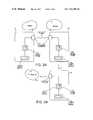
- FIG. 1is an illustration of a pair of prior Ir-enabled appliances 10 and 12 in standby mode. Standby mode is that condition to which the appliance returns when the appliance is not actively engaged in Ir communications.
- Each appliancecomprises (in pertinent part) an Ir transceiver system 14 and 16 that is powered by power supply means 18 and 20 for powering the electronics and mechanical devices contained within the appliances 10 and 12 .
- the power supply means 18 and 20may be external electrical power
- the means 18 and 20 that is pertinent to this discussionis a portable battery-type power supply means because its available charge is limited. The limited life span of the battery-type power supply means 18 and 20 is the focus of the present invention.
- the Ir transceiver systems 14 and 16operate in a constant, full-power demand condition, as demonstrated by the IrXS (Infrared transmission system) Power State indicators 22 and 24 (these are simply representations to indicate a power load condition—they are not intended to represent actual devices).
- the problem with the prior appliances 10 and 12resides with the “standby” or “sleep” mode of the If transceiver systems 14 and 16 .
- standby modeas represented by balloons 26 and 28 , there are no emissions from the systems 14 and 16 ; the systems 14 and 16 are simply monitoring their environment for a “discovery” signal.
- Discovery signalsare Ir signals in a particular frequency band, currently established by the IRDA (Infrared Data Association) at 9600 baud, that one appliance 10 or 12 sends to another appliance to “wake up” the other appliance in preparation for the commencement of Ir communications.
- the prior appliances 10 and 12are in full-power demand conditions 22 and 24 , even though they are sleeping.
- the transceiver systems 14 and 16are performing no work beyond simply listening, they are imposing the same drain on the power supply means 18 and 20 that a fully active transceiver 14 and 16 would draw.
- any reduction in power demandwill provide significant benefits to the user of these portable Ir-enabled appliances. What is needed, therefore, is a means for reducing the power drain on the power supply means 18 , for example, when portable Ir-enabled appliances are in standby mode.
- the device and systeminclude discovery signal receiver and power actuator module that consumes a fraction of the power of a conventional Ir transceiver system.
- the preferred device and systemmay be integral to a conventional Ir transceiver, or it may be a stand-alone system or device.
- the device and systemactivate full power to the Ir transceiver system upon recognition of an If discovery signal.
- the power-up signalalso be user-initiated.
- the switch means for providing full power to the Ir transceiver systembe in an open position while the Ir-enabled appliance is in a standby or sleep mode. It is a still further object that the device and system recognize a 9600 baud Ir discovery signal.
- FIG. 1is an illustration of a pair of prior Ir-enabled appliances in standby mode
- FIGS. 2A and 2Bare illustrations of the operation of the improved standby mode of the present invention.
- FIG. 3is an illustration of the power supply schematic of a typical prior Ir transceiver system
- FIG. 4is an illustration of a preferred low power discovery signal receiver and power actuator module of the present invention.
- FIG. 5is an illustration of a preferred integrated low power discovery signal receiver and power actuator system of the present invention.
- FIG. 6is a schematic diagram of a preferred low power discovery signal receiver and integrated power actuator system of the present invention.
- FIGS. 2A and Bare illustrations of the operation of the improved standby mode system and method of the present invention.
- the appliance 10has just sent a discovery signal 30 (represented by balloon 32 ) to the “sleeping” 34 Ir-enabled appliance 36 incorporating the system of the present invention.
- the discovery signal 30is received and recognized as such by the Ir transceiver system 16
- the IrXS (Ir transceiver system) power state 24remains in a low-power demand condition, a condition which places a very minor draw on the power supply means 20 .
- FIG. 2Breflects the transition that occurs within the appliance 36 once the discovery signal 30 has been received and recognized by the Ir transceiver system 16 .
- the IrXS power state 24switches to a full-power condition, thereby enabling the Ir transceiver system 16 to reply 38 to the other appliance 10 via Ir signal.
- the IrXS power state 24is in a low power condition simply “listening” for a discovery signal; after discovery, the IrXS power state 24 shifts to full power condition so that the transceiver system 16 can generate an Ir transmission.
- FIG. 3is an illustration of the power supply schematic of a typical prior Ir transceiver system 14 .
- the transceiver system 14comprises an Ir transmitter 40 for transmitting Ir signals and an Ir receiver 42 for receiving incident Ir signals. Both the transmitter 40 and receiver 42 are powered by “analog power” 44 ; analog power 44 is simply a power takeoff from the appliance's hardware that is segregated for use in analog devices (such as the Ir photodiodes)—the power is identical to that coming from the power supply means 18 .
- the Ir transmitter 40 and receiver 42are controlled by and/or communicate with a signal processor 44 that encodes and decodes data passing between the transmitter 40 /receiver 42 and a communications controller 46 .
- the communications controller 46then communicates with the central processing unit (CPU) or other systems elsewhere within the appliance.
- the signal processor 44 and communications controller 46receive their power from “digital power” 48 ; digital power 48 is, again, simply a power takeoff from the appliance that is confined to use in digital devices.
- the IrXS 22is in a full-power condition, as previously described in connection with FIGS. 1 and 2 .
- FIG. 4is an illustration of a preferred low power discovery signal receiver and power actuator module 60 of the present invention.
- the improved Ir transceiver system 50includes an Ir transmitter 40 , Ir receiver 42 , Signal Processor 44 and Communications Controller 46 , similar to the prior transceiver system.
- the analog and digital componentsare powered by switched analog and switched digital power 52 and 54 , respectively.
- the switched analog power 52 and switched digital power 54are activated by switch means 56 to energize the analog 44 and digital power 48 to their respective components.
- the switch means 56 for energizing and de-energizing the analog 52 and digital 54 switched powersmay be of a variety of conventional hardware and/or software combinations to provide, essentially, “on” and “off” control of the electrical power supply. Because the switched analog 52 and digital power 54 are configured to provide full power to the components of the transceiver system 50 , they are powered by the full power branch 58 . While the transceiver system 50 is in the sleep or standby mode, the switch means 56 is in an open condition and the switched analog 52 and digital power 54 are deactivated—full power to the transceiver system 50 is therefore switched off.
- the innovation of the present inventionlies in the discovery signal receiver and power actuator module 60 .
- This module 60comprises, in pertinent part, a simple Infrared receiver 62 and related discovery signal detection circuitry 64 .
- the receiver 62 and circuitry 64are configured to recognize incident Ir discovery signals (i.e. distinguishing them from other noise), and thereafter transmit a power-up signal 66 to the switch means 56 .
- the switch means 56Once the power-up signal 66 is received by the switch means 56 , the switched analog 52 and digital power 54 are activated to the transceiver system 50 , and the transceiver system 50 is enabled for full Ir signal transmission and receipt.
- the discovery signal receiver and power actuator module 60is powered by a low-power branch 68 ; it should be understood that the low power 68 and high power branches 58 are simply illustrations to assist in the understanding that the discovery signal receiver and power actuator module 60 draws only a small amount of power compared to the demand by the Ir transceiver system 50 . Furthermore, it should be appreciated that the power-up signal 66 may be manually overridden to either the “on” or “off” condition, in order to provide the user with additional flexibility in power demand control and system functionality.
- FIG. 5is an illustration of a preferred integrated low power discovery signal receiver and power actuator system of the present invention.
- the Ir transceiver system 70comprises an alternate signal processor 72 , which includes integrated discovery signal detection circuitry 64 connected to the low-power branch 68 .
- the conventional Ir receiver 42is able to operate (controlled by the discovery signal detection circuitry 64 ) in a low-power standby state.
- the circuitry 64recognizes a discovery signal received by the Ir receiver 42 , it, in cooperation with the communications controller 46 , generates the power-up signal 66 for activating the switch means 56 to energize the switched analog 52 and digital power 54 .
- the advantage of this embodimentis that only a single Ir receiver 42 is required; a simple operational modification to the existing transceiver system components is all that is necessary.
- the advantage of the system described in connection with FIG. 4is that it enables a conventional Ir-enabled appliance to be retrofitted to operate in a low-power standby mode.
- FIG. 6is a schematic diagram of a preferred low power discovery signal receiver and integrated power actuator system of the present invention, such as the system described above in connection with FIG. 5 .
- the UARToperates in a low-power condition to provide surveillance for a discovery signal—in this case a 9600 baud Ir signal.
- a discovery signalin this case a 9600 baud Ir signal.
- the low-power standby circuitryconsumes much less than 1 (one) mA of current. In fact, the standby power consumption is in the range of one-tenth of the conventional power consumption.
Landscapes
- Physics & Mathematics (AREA)
- Electromagnetism (AREA)
- Engineering & Computer Science (AREA)
- Computer Networks & Wireless Communication (AREA)
- Signal Processing (AREA)
- Optical Communication System (AREA)
- Mobile Radio Communication Systems (AREA)
- Transceivers (AREA)
- Selective Calling Equipment (AREA)
- Manufacture, Treatment Of Glass Fibers (AREA)
Abstract
Description
Claims (14)
Priority Applications (5)
| Application Number | Priority Date | Filing Date | Title |
|---|---|---|---|
| US09/135,154US7221285B1 (en) | 1998-08-17 | 1998-08-17 | System and method for providing an improved standby mode for infrared data transceivers |
| AT99941201TATE287153T1 (en) | 1998-08-17 | 1999-08-17 | METHOD AND APPARATUS FOR PROVIDING IMPROVED STANDBY OPERATION FOR INFRARED TRANSMITTER RECEIVER |
| PCT/US1999/018703WO2000010270A1 (en) | 1998-08-17 | 1999-08-17 | System and method for providing an improved standby mode for infrared data transceivers |
| DE69923165TDE69923165T2 (en) | 1998-08-17 | 1999-08-17 | METHOD AND DEVICE FOR PROVIDING AN IMPROVED STANDBY OPERATION FOR INFRARED SENDER RECEIVERS |
| EP99941201AEP1066696B1 (en) | 1998-08-17 | 1999-08-17 | System and method for providing an improved standby mode for infrared data transceivers |
Applications Claiming Priority (1)
| Application Number | Priority Date | Filing Date | Title |
|---|---|---|---|
| US09/135,154US7221285B1 (en) | 1998-08-17 | 1998-08-17 | System and method for providing an improved standby mode for infrared data transceivers |
Publications (1)
| Publication Number | Publication Date |
|---|---|
| US7221285B1true US7221285B1 (en) | 2007-05-22 |
Family
ID=22466789
Family Applications (1)
| Application Number | Title | Priority Date | Filing Date |
|---|---|---|---|
| US09/135,154Expired - Fee RelatedUS7221285B1 (en) | 1998-08-17 | 1998-08-17 | System and method for providing an improved standby mode for infrared data transceivers |
Country Status (5)
| Country | Link |
|---|---|
| US (1) | US7221285B1 (en) |
| EP (1) | EP1066696B1 (en) |
| AT (1) | ATE287153T1 (en) |
| DE (1) | DE69923165T2 (en) |
| WO (1) | WO2000010270A1 (en) |
Cited By (11)
| Publication number | Priority date | Publication date | Assignee | Title |
|---|---|---|---|---|
| US20020190797A1 (en)* | 2001-02-10 | 2002-12-19 | Carsten Deppe | Standby circuit for an electrical device |
| US20040239959A1 (en)* | 2001-09-12 | 2004-12-02 | Seiko Epson Corporation | Image processing apparatus and method |
| US20060104644A1 (en)* | 2004-11-15 | 2006-05-18 | Lg Electronics Inc. | Mobile communication terminal, apparatus for providing wire communications to the same and method thereof |
| US20060188254A1 (en)* | 2003-10-06 | 2006-08-24 | Marcus Schorpp | Communication link for communicating data |
| US20070196112A1 (en)* | 2006-02-23 | 2007-08-23 | Crews Darren S | Power save mode for an optical receiver |
| US20070294551A1 (en)* | 2006-06-14 | 2007-12-20 | Ching-Tsung Wu | Wireless remote control circuit with dual processing units and method therefor |
| US20110205559A1 (en)* | 2001-09-12 | 2011-08-25 | Seiko Epson Corporation | Hybrid printer and scan image copying method |
| US8144817B1 (en)* | 2004-08-06 | 2012-03-27 | Marvell International Ltd. | High-precision signal detection for high-speed receiver |
| US8341686B2 (en) | 2010-06-07 | 2012-12-25 | Echostar Technologies L.L.C. | Backup and restore of network configuration data using a remote controller device |
| US20150125154A1 (en)* | 2013-11-04 | 2015-05-07 | Samsung Electronics Co., Ltd. | Ir communication method and electronic device thereof |
| US9293032B2 (en) | 2006-12-29 | 2016-03-22 | Echostar Technologies L.L.C. | Two-way communication for control of an entertainment device |
Families Citing this family (12)
| Publication number | Priority date | Publication date | Assignee | Title |
|---|---|---|---|---|
| FR2855894B1 (en)* | 2003-06-06 | 2006-12-01 | Oposys | MOBILE ELEMENTS MANAGEMENT SYSTEM |
| CN100429682C (en)* | 2004-08-16 | 2008-10-29 | 美国博通公司 | Method and system for reducing energy consumption of IrDA activated devices |
| US20060034611A1 (en)* | 2004-08-16 | 2006-02-16 | Weidong Li | Method and system for reducing power consumption of IrDA enabled handsets by turning on/off an IrDA port dynamically |
| GB2424777A (en)* | 2005-04-01 | 2006-10-04 | Agilent Technologies Inc | Transmitting a wake-up instruction to a receiving device by modulating data on illumination light, such as that provided by an electroluminescent room light. |
| US7912381B2 (en) | 2006-06-02 | 2011-03-22 | Standard Microsystems Corporation | Transmission network having an optical receiver that utilizes dual power pins and a single status pin to lower power consumption, lower manufacturing cost, and increase transmission efficiency |
| EP2477348A1 (en) | 2006-02-17 | 2012-07-18 | Standard Microsystems Corporation | Transmission network having an optical receiver that utilizes dual power pins and a single status pin to lower power consumption, lower manufacturing cost, and increase transmisson efficiency |
| CN101385294B (en)* | 2006-02-17 | 2011-12-07 | 标准微体系有限公司 | System and method for transferring different types of stream data and packet data over an Ethernet transmission line using frame and packet structures distinguished by Ethernet coding violations |
| KR101422805B1 (en) | 2006-02-17 | 2014-07-23 | 에스엠에스씨 유럽 게엠베하 | System and method for transferring data packets through a communication system |
| KR100752524B1 (en) | 2006-05-26 | 2007-08-29 | 주식회사 에이디텍 | Wait time reduction circuit of infrared transceiver |
| US8942564B2 (en)* | 2012-11-07 | 2015-01-27 | Qualcomm Incorporated | Methods and apparatus for communicating information using visible light signals and/or radio signals |
| GB2569288A (en)* | 2017-12-07 | 2019-06-19 | Purelifi Ltd | Low power receiver apparatus |
| EP4059272A1 (en) | 2019-11-11 | 2022-09-21 | Telefonaktiebolaget LM Ericsson (publ) | Wireless communication device |
Citations (11)
| Publication number | Priority date | Publication date | Assignee | Title |
|---|---|---|---|---|
| EP0317007A1 (en) | 1987-11-18 | 1989-05-24 | Koninklijke Philips Electronics N.V. | Remote control system using a wake up signal |
| US5239295A (en) | 1990-04-16 | 1993-08-24 | Motorola, Inc. | Serial light interface which also functions as an ambient light detector |
| US5606443A (en) | 1993-07-28 | 1997-02-25 | Sony Corporation | Control circuit for entertainment system demonstration |
| EP0772307A1 (en) | 1995-10-31 | 1997-05-07 | Nokia Mobile Phones Ltd. | Communication protocol for half-duplex traffic |
| US5706110A (en)* | 1995-01-13 | 1998-01-06 | Nokia Mobile Phones, Ltd. | Method and equipment for saving power in infrared data transmission |
| US5973611A (en)* | 1995-03-27 | 1999-10-26 | Ut Automotive Dearborn, Inc. | Hands-free remote entry system |
| US6157476A (en) | 1996-12-21 | 2000-12-05 | Temic Telefunken Microelectronic Gmbh | Transceiver component for data transmission |
| US6169295B1 (en) | 1998-05-29 | 2001-01-02 | Maxim Integrated Products, Inc. | Infrared transceiver module and method for making same |
| US6301035B1 (en) | 1997-06-28 | 2001-10-09 | Vishay Semiconductor Gmbh | Component for optical data transmission |
| US6570188B1 (en) | 1996-12-19 | 2003-05-27 | Temic Telefunken Microelectronic Gmbh | Optoelectronic component for data transmission |
| US6810216B1 (en) | 1999-07-02 | 2004-10-26 | Nokia Corporation | Fast infrared transceiver with reduced power consumption |
- 1998
- 1998-08-17USUS09/135,154patent/US7221285B1/ennot_activeExpired - Fee Related
- 1999
- 1999-08-17EPEP99941201Apatent/EP1066696B1/ennot_activeExpired - Lifetime
- 1999-08-17ATAT99941201Tpatent/ATE287153T1/ennot_activeIP Right Cessation
- 1999-08-17DEDE69923165Tpatent/DE69923165T2/ennot_activeExpired - Fee Related
- 1999-08-17WOPCT/US1999/018703patent/WO2000010270A1/enactiveIP Right Grant
Patent Citations (12)
| Publication number | Priority date | Publication date | Assignee | Title |
|---|---|---|---|---|
| EP0317007A1 (en) | 1987-11-18 | 1989-05-24 | Koninklijke Philips Electronics N.V. | Remote control system using a wake up signal |
| US5115236A (en)* | 1987-11-18 | 1992-05-19 | U.S. Philips Corporation | Remote control system using a wake up signal |
| US5239295A (en) | 1990-04-16 | 1993-08-24 | Motorola, Inc. | Serial light interface which also functions as an ambient light detector |
| US5606443A (en) | 1993-07-28 | 1997-02-25 | Sony Corporation | Control circuit for entertainment system demonstration |
| US5706110A (en)* | 1995-01-13 | 1998-01-06 | Nokia Mobile Phones, Ltd. | Method and equipment for saving power in infrared data transmission |
| US5973611A (en)* | 1995-03-27 | 1999-10-26 | Ut Automotive Dearborn, Inc. | Hands-free remote entry system |
| EP0772307A1 (en) | 1995-10-31 | 1997-05-07 | Nokia Mobile Phones Ltd. | Communication protocol for half-duplex traffic |
| US6570188B1 (en) | 1996-12-19 | 2003-05-27 | Temic Telefunken Microelectronic Gmbh | Optoelectronic component for data transmission |
| US6157476A (en) | 1996-12-21 | 2000-12-05 | Temic Telefunken Microelectronic Gmbh | Transceiver component for data transmission |
| US6301035B1 (en) | 1997-06-28 | 2001-10-09 | Vishay Semiconductor Gmbh | Component for optical data transmission |
| US6169295B1 (en) | 1998-05-29 | 2001-01-02 | Maxim Integrated Products, Inc. | Infrared transceiver module and method for making same |
| US6810216B1 (en) | 1999-07-02 | 2004-10-26 | Nokia Corporation | Fast infrared transceiver with reduced power consumption |
Non-Patent Citations (7)
| Title |
|---|
| "Infrared Transceiver Module TFDU4101" data sheet, Vishay Semiconductors, document No. 82525, 16 pages (Nov. 2, 2000). |
| "Infrared Transceiver Module TFDU6101" data sheet, Vishay Semiconductors, document No. 81288, 15 pages (Sep. 26, 2006). |
| HSDL-1001 Infrared IrDA Compliant Transceiver data sheet, Agilent Technologies, 8 pages (Nov. 1999). |
| Infrared Data Association Serial Infrared Link Access Protocol (IRLAP), Infrared Data Association, HTTP://WWW.IRDA.ORG/STANDARDS/SPECIFICATIONS.ASP, pp. 5-7, 15, 27-30, 34, 47-54. |
| Infrared Data Association Serial Link Access Protocal (IrLAP) Specification, Infrared Data Association, http://www.irda.org/standards/specifications.asp, pp. 94-95 (1996).* |
| MiniSIR2 IrDA 1.0 Transceiver Module data sheet, Novalog, Inc., 18 pages (Oct. 2000). |
| ZHX1403 SIR UltraSlim Transceiver data sheet, Zilog Inc., 15 pages (2005). |
Cited By (23)
| Publication number | Priority date | Publication date | Assignee | Title |
|---|---|---|---|---|
| US7444530B2 (en)* | 2001-02-10 | 2008-10-28 | Nxp B.V. | Standby circuit for an electrical device |
| US20020190797A1 (en)* | 2001-02-10 | 2002-12-19 | Carsten Deppe | Standby circuit for an electrical device |
| US8368949B2 (en) | 2001-09-12 | 2013-02-05 | Seiko Epson Corporation | Hybrid printer and scan image copying method |
| US20100220367A1 (en)* | 2001-09-12 | 2010-09-02 | Seiko Epson Corporation | Image processing apparatus and method |
| US8395807B2 (en) | 2001-09-12 | 2013-03-12 | Seiko Epson Corporation | Image processing apparatus and method for borderless printing |
| US20040239959A1 (en)* | 2001-09-12 | 2004-12-02 | Seiko Epson Corporation | Image processing apparatus and method |
| US8208164B2 (en) | 2001-09-12 | 2012-06-26 | Seiko Epson Corporation | Image processing apparatus and method |
| US20090067011A1 (en)* | 2001-09-12 | 2009-03-12 | Seiko Epson Corporation | Image processing apparatus and method |
| US20110205559A1 (en)* | 2001-09-12 | 2011-08-25 | Seiko Epson Corporation | Hybrid printer and scan image copying method |
| US7742198B2 (en)* | 2001-09-12 | 2010-06-22 | Seiko Epson Corporation | Image processing apparatus and method |
| US7636523B2 (en)* | 2003-10-06 | 2009-12-22 | Nokia Corporation | Communication link for communicating data |
| US20060188254A1 (en)* | 2003-10-06 | 2006-08-24 | Marcus Schorpp | Communication link for communicating data |
| US8144817B1 (en)* | 2004-08-06 | 2012-03-27 | Marvell International Ltd. | High-precision signal detection for high-speed receiver |
| US20060104644A1 (en)* | 2004-11-15 | 2006-05-18 | Lg Electronics Inc. | Mobile communication terminal, apparatus for providing wire communications to the same and method thereof |
| US20070196112A1 (en)* | 2006-02-23 | 2007-08-23 | Crews Darren S | Power save mode for an optical receiver |
| US20070294551A1 (en)* | 2006-06-14 | 2007-12-20 | Ching-Tsung Wu | Wireless remote control circuit with dual processing units and method therefor |
| US9293032B2 (en) | 2006-12-29 | 2016-03-22 | Echostar Technologies L.L.C. | Two-way communication for control of an entertainment device |
| US8341686B2 (en) | 2010-06-07 | 2012-12-25 | Echostar Technologies L.L.C. | Backup and restore of network configuration data using a remote controller device |
| US8832770B2 (en) | 2010-06-07 | 2014-09-09 | Echostar Technologies L.L.C. | Backup and restore of network configuration data using a remote controller device |
| US20150125154A1 (en)* | 2013-11-04 | 2015-05-07 | Samsung Electronics Co., Ltd. | Ir communication method and electronic device thereof |
| KR20150051497A (en)* | 2013-11-04 | 2015-05-13 | 삼성전자주식회사 | Infrared ray communication method of electronic apparatus and electronic appparatus thereof |
| US10002528B2 (en)* | 2013-11-04 | 2018-06-19 | Samsung Electronics Co., Ltd. | IR communication method and electronic device thereof |
| EP2869543B1 (en)* | 2013-11-04 | 2019-06-12 | Samsung Electronics Co., Ltd | IR communication method and electronic device thereof |
Also Published As
| Publication number | Publication date |
|---|---|
| WO2000010270A1 (en) | 2000-02-24 |
| EP1066696B1 (en) | 2005-01-12 |
| DE69923165T2 (en) | 2006-02-23 |
| ATE287153T1 (en) | 2005-01-15 |
| DE69923165D1 (en) | 2005-02-17 |
| EP1066696A1 (en) | 2001-01-10 |
Similar Documents
| Publication | Publication Date | Title |
|---|---|---|
| US7221285B1 (en) | System and method for providing an improved standby mode for infrared data transceivers | |
| US6810216B1 (en) | Fast infrared transceiver with reduced power consumption | |
| EP0852856B1 (en) | Infrared wireless communication between electronic system components | |
| US7636523B2 (en) | Communication link for communicating data | |
| US20060022802A1 (en) | Radio frequency identification-based power management system and method for wireless communication devices | |
| KR950703230A (en) | Apparatus For Adapting An Electrical Communications Port To An Optical Communications Port | |
| US20120027061A1 (en) | Wireless modem device, wireless modem system, wireless modem device sleep/wake-up method, and terminal | |
| US20070081504A1 (en) | Method of managing power consumption of portable computer and portable computer using the same | |
| US20190068247A1 (en) | Nfc device and power management method | |
| US7134027B2 (en) | Initiating computer system power-up from a USB keyboard | |
| US7206603B2 (en) | Cellular radio telephone set | |
| US6333801B1 (en) | Electronic equipment for optical communication capable of saving power | |
| US6590682B1 (en) | Infrared signal communication system and method including transmission means having automatic gain control | |
| CN101299619B (en) | Wireless transmission device capable of controlling voltage along with load | |
| ATE376228T1 (en) | RADIO DATA TRANSMISSION DEVICE | |
| US20040106377A1 (en) | Communications interface device for receiving digital signals | |
| JP7249211B2 (en) | Wireless device wake-up circuit | |
| KR19990022851U (en) | Personal wireless transmitter and receiver to save battery power | |
| GB2424777A (en) | Transmitting a wake-up instruction to a receiving device by modulating data on illumination light, such as that provided by an electroluminescent room light. | |
| US6421546B1 (en) | Signal transmission circuit of a wireless telephone handset | |
| JPH10133788A (en) | Radio type information inputting device with power source controlling function | |
| WO2021091833A1 (en) | Signal detection circuit | |
| EP1630926A3 (en) | Power switching device in mobile communication terminal | |
| KR20070020952A (en) | Wi-Fi module having a host wake-up function and a host wake-up method in the Wi-Fi module | |
| CN105306079A (en) | Wireless communication receiver and wireless communication method |
Legal Events
| Date | Code | Title | Description |
|---|---|---|---|
| AS | Assignment | Owner name:CALIBRE, INC., CALIFORNIA Free format text:ASSIGNMENT OF ASSIGNORS INTEREST;ASSIGNOR:HAMILTON, T. ALLAN;REEL/FRAME:009403/0842 Effective date:19980729 | |
| AS | Assignment | Owner name:ZILOG, INC., CALIFORNIA Free format text:ASSIGNMENT OF ASSIGNORS INTEREST;ASSIGNOR:CALIBRE, INC.;REEL/FRAME:013100/0136 Effective date:20000727 | |
| STCF | Information on status: patent grant | Free format text:PATENTED CASE | |
| CC | Certificate of correction | ||
| CC | Certificate of correction | ||
| FEPP | Fee payment procedure | Free format text:PAT HOLDER NO LONGER CLAIMS SMALL ENTITY STATUS, ENTITY STATUS SET TO UNDISCOUNTED (ORIGINAL EVENT CODE: STOL); ENTITY STATUS OF PATENT OWNER: LARGE ENTITY Free format text:PAT HOLDER CLAIMS SMALL ENTITY STATUS, ENTITY STATUS SET TO SMALL (ORIGINAL EVENT CODE: LTOS); ENTITY STATUS OF PATENT OWNER: LARGE ENTITY | |
| REFU | Refund | Free format text:REFUND - SURCHARGE, PETITION TO ACCEPT PYMT AFTER EXP, UNINTENTIONAL (ORIGINAL EVENT CODE: R2551); ENTITY STATUS OF PATENT OWNER: LARGE ENTITY | |
| AS | Assignment | Owner name:IXYS CH GMBH, SWITZERLAND Free format text:ASSIGNMENT OF ASSIGNORS INTEREST;ASSIGNOR:ZILOG, INC.;REEL/FRAME:024964/0132 Effective date:20100217 | |
| FPAY | Fee payment | Year of fee payment:4 | |
| FPAY | Fee payment | Year of fee payment:8 | |
| AS | Assignment | Owner name:IXYS INTL LIMITED, CAYMAN ISLANDS Free format text:ASSIGNMENT OF ASSIGNORS INTEREST;ASSIGNOR:IXYS CH GMBH;REEL/FRAME:035665/0589 Effective date:20150515 | |
| FEPP | Fee payment procedure | Free format text:MAINTENANCE FEE REMINDER MAILED (ORIGINAL EVENT CODE: REM.); ENTITY STATUS OF PATENT OWNER: LARGE ENTITY | |
| LAPS | Lapse for failure to pay maintenance fees | Free format text:PATENT EXPIRED FOR FAILURE TO PAY MAINTENANCE FEES (ORIGINAL EVENT CODE: EXP.); ENTITY STATUS OF PATENT OWNER: LARGE ENTITY | |
| STCH | Information on status: patent discontinuation | Free format text:PATENT EXPIRED DUE TO NONPAYMENT OF MAINTENANCE FEES UNDER 37 CFR 1.362 | |
| FP | Lapsed due to failure to pay maintenance fee | Effective date:20190522 |