US7220282B2 - Annulus-reinforcing band - Google Patents
Annulus-reinforcing bandDownload PDFInfo
- Publication number
- US7220282B2 US7220282B2US11/447,615US44761506AUS7220282B2US 7220282 B2US7220282 B2US 7220282B2US 44761506 AUS44761506 AUS 44761506AUS 7220282 B2US7220282 B2US 7220282B2
- Authority
- US
- United States
- Prior art keywords
- mesh member
- fill
- fill material
- space
- band
- Prior art date
- Legal status (The legal status is an assumption and is not a legal conclusion. Google has not performed a legal analysis and makes no representation as to the accuracy of the status listed.)
- Expired - Lifetime
Links
- 239000000463materialSubstances0.000claimsabstractdescription117
- 239000011148porous materialSubstances0.000claimsdescription24
- 238000000034methodMethods0.000claimsdescription15
- 238000003780insertionMethods0.000claimsdescription13
- 230000037431insertionEffects0.000claimsdescription13
- 230000000087stabilizing effectEffects0.000claimsdescription7
- 239000007788liquidSubstances0.000claimsdescription5
- 239000002245particleSubstances0.000claimsdescription5
- 230000004044responseEffects0.000claimsdescription2
- 239000000725suspensionSubstances0.000claims4
- 210000000988bone and boneAnatomy0.000description23
- 239000000835fiberSubstances0.000description21
- 230000004927fusionEffects0.000description12
- 230000001419dependent effectEffects0.000description11
- 210000001519tissueAnatomy0.000description11
- 239000007943implantSubstances0.000description9
- 238000010276constructionMethods0.000description8
- 206010061246Intervertebral disc degenerationDiseases0.000description7
- 208000008035Back PainDiseases0.000description6
- 208000018180degenerative disc diseaseDiseases0.000description6
- 230000001976improved effectEffects0.000description6
- 208000021600intervertebral disc degenerative diseaseDiseases0.000description6
- 229910052751metalInorganic materials0.000description6
- 239000002184metalSubstances0.000description6
- 239000007787solidSubstances0.000description6
- 208000002193PainDiseases0.000description5
- 230000036407painEffects0.000description5
- 230000008468bone growthEffects0.000description4
- 208000037265diseases, disorders, signs and symptomsDiseases0.000description4
- 239000004744fabricSubstances0.000description4
- 230000008859changeEffects0.000description3
- 230000006835compressionEffects0.000description3
- 238000007906compressionMethods0.000description3
- 201000010099diseaseDiseases0.000description3
- 239000003814drugSubstances0.000description3
- 230000006870functionEffects0.000description3
- HLXZNVUGXRDIFK-UHFFFAOYSA-Nnickel titaniumChemical compound[Ti].[Ti].[Ti].[Ti].[Ti].[Ti].[Ti].[Ti].[Ti].[Ti].[Ti].[Ni].[Ni].[Ni].[Ni].[Ni].[Ni].[Ni].[Ni].[Ni].[Ni].[Ni].[Ni].[Ni].[Ni]HLXZNVUGXRDIFK-UHFFFAOYSA-N0.000description3
- 229910001000nickel titaniumInorganic materials0.000description3
- 230000002787reinforcementEffects0.000description3
- 208000032843HemorrhageDiseases0.000description2
- 206010019909HerniaDiseases0.000description2
- 210000003484anatomyAnatomy0.000description2
- 230000008901benefitEffects0.000description2
- 239000000316bone substituteSubstances0.000description2
- 230000006378damageEffects0.000description2
- 238000005516engineering processMethods0.000description2
- 239000012530fluidSubstances0.000description2
- 239000008187granular materialSubstances0.000description2
- 238000002513implantationMethods0.000description2
- 238000002347injectionMethods0.000description2
- 239000007924injectionSubstances0.000description2
- 230000002093peripheral effectEffects0.000description2
- 229920000728polyesterPolymers0.000description2
- 230000008569processEffects0.000description2
- 238000012552reviewMethods0.000description2
- 239000012781shape memory materialSubstances0.000description2
- 210000004872soft tissueAnatomy0.000description2
- 208000008930Low Back PainDiseases0.000description1
- 206010029174Nerve compressionDiseases0.000description1
- 241000906034OrthopsSpecies0.000description1
- 206010033799ParalysisDiseases0.000description1
- 208000008765SciaticaDiseases0.000description1
- 229910000831SteelInorganic materials0.000description1
- RTAQQCXQSZGOHL-UHFFFAOYSA-NTitaniumChemical compound[Ti]RTAQQCXQSZGOHL-UHFFFAOYSA-N0.000description1
- 208000027418Wounds and injuryDiseases0.000description1
- 230000009471actionEffects0.000description1
- 239000011324beadSubstances0.000description1
- 238000005452bendingMethods0.000description1
- 230000000975bioactive effectEffects0.000description1
- 239000003462bioceramicSubstances0.000description1
- 239000000560biocompatible materialSubstances0.000description1
- 230000015572biosynthetic processEffects0.000description1
- 208000034158bleedingDiseases0.000description1
- 230000000740bleeding effectEffects0.000description1
- 210000004204blood vesselAnatomy0.000description1
- 210000000845cartilageAnatomy0.000description1
- 239000004568cementSubstances0.000description1
- 238000004891communicationMethods0.000description1
- 230000003247decreasing effectEffects0.000description1
- 230000007850degenerationEffects0.000description1
- 230000002542deteriorative effectEffects0.000description1
- 238000011161developmentMethods0.000description1
- 208000035475disorderDiseases0.000description1
- 238000006073displacement reactionMethods0.000description1
- 229940079593drugDrugs0.000description1
- 238000012377drug deliveryMethods0.000description1
- 238000002474experimental methodMethods0.000description1
- 239000012634fragmentSubstances0.000description1
- 239000007789gasSubstances0.000description1
- 230000012010growthEffects0.000description1
- 230000036541healthEffects0.000description1
- 229910052588hydroxylapatiteInorganic materials0.000description1
- 230000006872improvementEffects0.000description1
- 230000001939inductive effectEffects0.000description1
- 230000000266injurious effectEffects0.000description1
- 208000014674injuryDiseases0.000description1
- 238000009533lab testMethods0.000description1
- 238000002690local anesthesiaMethods0.000description1
- 210000004705lumbosacral regionAnatomy0.000description1
- 238000007726management methodMethods0.000description1
- 230000003387muscularEffects0.000description1
- 230000001537neural effectEffects0.000description1
- 239000011824nuclear materialSubstances0.000description1
- 230000000399orthopedic effectEffects0.000description1
- 230000011164ossificationEffects0.000description1
- 238000007500overflow downdraw methodMethods0.000description1
- 239000011236particulate materialSubstances0.000description1
- 230000035515penetrationEffects0.000description1
- XYJRXVWERLGGKC-UHFFFAOYSA-Dpentacalcium;hydroxide;triphosphateChemical compound[OH-].[Ca+2].[Ca+2].[Ca+2].[Ca+2].[Ca+2].[O-]P([O-])([O-])=O.[O-]P([O-])([O-])=O.[O-]P([O-])([O-])=OXYJRXVWERLGGKC-UHFFFAOYSA-D0.000description1
- 230000003014reinforcing effectEffects0.000description1
- 230000008439repair processEffects0.000description1
- 238000011160researchMethods0.000description1
- 238000012827research and developmentMethods0.000description1
- 238000005204segregationMethods0.000description1
- 238000000926separation methodMethods0.000description1
- 239000011343solid materialSubstances0.000description1
- 239000000243solutionSubstances0.000description1
- 210000000278spinal cordAnatomy0.000description1
- 210000001032spinal nerveAnatomy0.000description1
- 230000006641stabilisationEffects0.000description1
- 238000011105stabilizationMethods0.000description1
- 239000010959steelSubstances0.000description1
- 230000000638stimulationEffects0.000description1
- 230000003319supportive effectEffects0.000description1
- 238000001356surgical procedureMethods0.000description1
- 208000024891symptomDiseases0.000description1
- 229940124597therapeutic agentDrugs0.000description1
- 239000010936titaniumSubstances0.000description1
- 229910052719titaniumInorganic materials0.000description1
- 230000002792vascularEffects0.000description1
- 238000009941weavingMethods0.000description1
- -1wovenSubstances0.000description1
Images


Classifications
- A—HUMAN NECESSITIES
- A61—MEDICAL OR VETERINARY SCIENCE; HYGIENE
- A61F—FILTERS IMPLANTABLE INTO BLOOD VESSELS; PROSTHESES; DEVICES PROVIDING PATENCY TO, OR PREVENTING COLLAPSING OF, TUBULAR STRUCTURES OF THE BODY, e.g. STENTS; ORTHOPAEDIC, NURSING OR CONTRACEPTIVE DEVICES; FOMENTATION; TREATMENT OR PROTECTION OF EYES OR EARS; BANDAGES, DRESSINGS OR ABSORBENT PADS; FIRST-AID KITS
- A61F2/00—Filters implantable into blood vessels; Prostheses, i.e. artificial substitutes or replacements for parts of the body; Appliances for connecting them with the body; Devices providing patency to, or preventing collapsing of, tubular structures of the body, e.g. stents
- A61F2/02—Prostheses implantable into the body
- A61F2/30—Joints
- A61F2/44—Joints for the spine, e.g. vertebrae, spinal discs
- A61F2/442—Intervertebral or spinal discs, e.g. resilient
- A—HUMAN NECESSITIES
- A61—MEDICAL OR VETERINARY SCIENCE; HYGIENE
- A61F—FILTERS IMPLANTABLE INTO BLOOD VESSELS; PROSTHESES; DEVICES PROVIDING PATENCY TO, OR PREVENTING COLLAPSING OF, TUBULAR STRUCTURES OF THE BODY, e.g. STENTS; ORTHOPAEDIC, NURSING OR CONTRACEPTIVE DEVICES; FOMENTATION; TREATMENT OR PROTECTION OF EYES OR EARS; BANDAGES, DRESSINGS OR ABSORBENT PADS; FIRST-AID KITS
- A61F2/00—Filters implantable into blood vessels; Prostheses, i.e. artificial substitutes or replacements for parts of the body; Appliances for connecting them with the body; Devices providing patency to, or preventing collapsing of, tubular structures of the body, e.g. stents
- A61F2/02—Prostheses implantable into the body
- A61F2/30—Joints
- A61F2/44—Joints for the spine, e.g. vertebrae, spinal discs
- A61F2/441—Joints for the spine, e.g. vertebrae, spinal discs made of inflatable pockets or chambers filled with fluid, e.g. with hydrogel
- A—HUMAN NECESSITIES
- A61—MEDICAL OR VETERINARY SCIENCE; HYGIENE
- A61F—FILTERS IMPLANTABLE INTO BLOOD VESSELS; PROSTHESES; DEVICES PROVIDING PATENCY TO, OR PREVENTING COLLAPSING OF, TUBULAR STRUCTURES OF THE BODY, e.g. STENTS; ORTHOPAEDIC, NURSING OR CONTRACEPTIVE DEVICES; FOMENTATION; TREATMENT OR PROTECTION OF EYES OR EARS; BANDAGES, DRESSINGS OR ABSORBENT PADS; FIRST-AID KITS
- A61F2/00—Filters implantable into blood vessels; Prostheses, i.e. artificial substitutes or replacements for parts of the body; Appliances for connecting them with the body; Devices providing patency to, or preventing collapsing of, tubular structures of the body, e.g. stents
- A61F2/02—Prostheses implantable into the body
- A61F2/30—Joints
- A61F2/46—Special tools for implanting artificial joints
- A61F2/4601—Special tools for implanting artificial joints for introducing bone substitute, for implanting bone graft implants or for compacting them in the bone cavity
- A—HUMAN NECESSITIES
- A61—MEDICAL OR VETERINARY SCIENCE; HYGIENE
- A61F—FILTERS IMPLANTABLE INTO BLOOD VESSELS; PROSTHESES; DEVICES PROVIDING PATENCY TO, OR PREVENTING COLLAPSING OF, TUBULAR STRUCTURES OF THE BODY, e.g. STENTS; ORTHOPAEDIC, NURSING OR CONTRACEPTIVE DEVICES; FOMENTATION; TREATMENT OR PROTECTION OF EYES OR EARS; BANDAGES, DRESSINGS OR ABSORBENT PADS; FIRST-AID KITS
- A61F2/00—Filters implantable into blood vessels; Prostheses, i.e. artificial substitutes or replacements for parts of the body; Appliances for connecting them with the body; Devices providing patency to, or preventing collapsing of, tubular structures of the body, e.g. stents
- A61F2/02—Prostheses implantable into the body
- A61F2/30—Joints
- A61F2/46—Special tools for implanting artificial joints
- A61F2/4603—Special tools for implanting artificial joints for insertion or extraction of endoprosthetic joints or of accessories thereof
- A61F2/4611—Special tools for implanting artificial joints for insertion or extraction of endoprosthetic joints or of accessories thereof of spinal prostheses
- A—HUMAN NECESSITIES
- A61—MEDICAL OR VETERINARY SCIENCE; HYGIENE
- A61B—DIAGNOSIS; SURGERY; IDENTIFICATION
- A61B17/00—Surgical instruments, devices or methods
- A61B17/56—Surgical instruments or methods for treatment of bones or joints; Devices specially adapted therefor
- A61B17/58—Surgical instruments or methods for treatment of bones or joints; Devices specially adapted therefor for osteosynthesis, e.g. bone plates, screws or setting implements
- A61B17/68—Internal fixation devices, including fasteners and spinal fixators, even if a part thereof projects from the skin
- A61B17/70—Spinal positioners or stabilisers, e.g. stabilisers comprising fluid filler in an implant
- A61B17/7094—Solid vertebral fillers; devices for inserting such fillers
- A61B17/7095—Solid vertebral fillers; devices for inserting such fillers the filler comprising unlinked macroscopic particles
- A—HUMAN NECESSITIES
- A61—MEDICAL OR VETERINARY SCIENCE; HYGIENE
- A61B—DIAGNOSIS; SURGERY; IDENTIFICATION
- A61B17/00—Surgical instruments, devices or methods
- A61B17/56—Surgical instruments or methods for treatment of bones or joints; Devices specially adapted therefor
- A61B17/58—Surgical instruments or methods for treatment of bones or joints; Devices specially adapted therefor for osteosynthesis, e.g. bone plates, screws or setting implements
- A61B17/68—Internal fixation devices, including fasteners and spinal fixators, even if a part thereof projects from the skin
- A61B17/70—Spinal positioners or stabilisers, e.g. stabilisers comprising fluid filler in an implant
- A61B17/7097—Stabilisers comprising fluid filler in an implant, e.g. balloon; devices for inserting or filling such implants
- A61B17/7098—Stabilisers comprising fluid filler in an implant, e.g. balloon; devices for inserting or filling such implants wherein the implant is permeable or has openings, e.g. fenestrated screw
- A—HUMAN NECESSITIES
- A61—MEDICAL OR VETERINARY SCIENCE; HYGIENE
- A61F—FILTERS IMPLANTABLE INTO BLOOD VESSELS; PROSTHESES; DEVICES PROVIDING PATENCY TO, OR PREVENTING COLLAPSING OF, TUBULAR STRUCTURES OF THE BODY, e.g. STENTS; ORTHOPAEDIC, NURSING OR CONTRACEPTIVE DEVICES; FOMENTATION; TREATMENT OR PROTECTION OF EYES OR EARS; BANDAGES, DRESSINGS OR ABSORBENT PADS; FIRST-AID KITS
- A61F2/00—Filters implantable into blood vessels; Prostheses, i.e. artificial substitutes or replacements for parts of the body; Appliances for connecting them with the body; Devices providing patency to, or preventing collapsing of, tubular structures of the body, e.g. stents
- A61F2/02—Prostheses implantable into the body
- A61F2/28—Bones
- A61F2002/2817—Bone stimulation by chemical reactions or by osteogenic or biological products for enhancing ossification, e.g. by bone morphogenetic or morphogenic proteins [BMP] or by transforming growth factors [TGF]
- A—HUMAN NECESSITIES
- A61—MEDICAL OR VETERINARY SCIENCE; HYGIENE
- A61F—FILTERS IMPLANTABLE INTO BLOOD VESSELS; PROSTHESES; DEVICES PROVIDING PATENCY TO, OR PREVENTING COLLAPSING OF, TUBULAR STRUCTURES OF THE BODY, e.g. STENTS; ORTHOPAEDIC, NURSING OR CONTRACEPTIVE DEVICES; FOMENTATION; TREATMENT OR PROTECTION OF EYES OR EARS; BANDAGES, DRESSINGS OR ABSORBENT PADS; FIRST-AID KITS
- A61F2/00—Filters implantable into blood vessels; Prostheses, i.e. artificial substitutes or replacements for parts of the body; Appliances for connecting them with the body; Devices providing patency to, or preventing collapsing of, tubular structures of the body, e.g. stents
- A61F2/02—Prostheses implantable into the body
- A61F2/28—Bones
- A61F2002/2821—Bone stimulation by electromagnetic fields or electric current for enhancing ossification
- A—HUMAN NECESSITIES
- A61—MEDICAL OR VETERINARY SCIENCE; HYGIENE
- A61F—FILTERS IMPLANTABLE INTO BLOOD VESSELS; PROSTHESES; DEVICES PROVIDING PATENCY TO, OR PREVENTING COLLAPSING OF, TUBULAR STRUCTURES OF THE BODY, e.g. STENTS; ORTHOPAEDIC, NURSING OR CONTRACEPTIVE DEVICES; FOMENTATION; TREATMENT OR PROTECTION OF EYES OR EARS; BANDAGES, DRESSINGS OR ABSORBENT PADS; FIRST-AID KITS
- A61F2/00—Filters implantable into blood vessels; Prostheses, i.e. artificial substitutes or replacements for parts of the body; Appliances for connecting them with the body; Devices providing patency to, or preventing collapsing of, tubular structures of the body, e.g. stents
- A61F2/02—Prostheses implantable into the body
- A61F2/28—Bones
- A61F2002/2835—Bone graft implants for filling a bony defect or an endoprosthesis cavity, e.g. by synthetic material or biological material
- A—HUMAN NECESSITIES
- A61—MEDICAL OR VETERINARY SCIENCE; HYGIENE
- A61F—FILTERS IMPLANTABLE INTO BLOOD VESSELS; PROSTHESES; DEVICES PROVIDING PATENCY TO, OR PREVENTING COLLAPSING OF, TUBULAR STRUCTURES OF THE BODY, e.g. STENTS; ORTHOPAEDIC, NURSING OR CONTRACEPTIVE DEVICES; FOMENTATION; TREATMENT OR PROTECTION OF EYES OR EARS; BANDAGES, DRESSINGS OR ABSORBENT PADS; FIRST-AID KITS
- A61F2/00—Filters implantable into blood vessels; Prostheses, i.e. artificial substitutes or replacements for parts of the body; Appliances for connecting them with the body; Devices providing patency to, or preventing collapsing of, tubular structures of the body, e.g. stents
- A61F2/02—Prostheses implantable into the body
- A61F2/30—Joints
- A61F2002/30001—Additional features of subject-matter classified in A61F2/28, A61F2/30 and subgroups thereof
- A61F2002/30003—Material related properties of the prosthesis or of a coating on the prosthesis
- A61F2002/3006—Properties of materials and coating materials
- A61F2002/30092—Properties of materials and coating materials using shape memory or superelastic materials, e.g. nitinol
- A—HUMAN NECESSITIES
- A61—MEDICAL OR VETERINARY SCIENCE; HYGIENE
- A61F—FILTERS IMPLANTABLE INTO BLOOD VESSELS; PROSTHESES; DEVICES PROVIDING PATENCY TO, OR PREVENTING COLLAPSING OF, TUBULAR STRUCTURES OF THE BODY, e.g. STENTS; ORTHOPAEDIC, NURSING OR CONTRACEPTIVE DEVICES; FOMENTATION; TREATMENT OR PROTECTION OF EYES OR EARS; BANDAGES, DRESSINGS OR ABSORBENT PADS; FIRST-AID KITS
- A61F2/00—Filters implantable into blood vessels; Prostheses, i.e. artificial substitutes or replacements for parts of the body; Appliances for connecting them with the body; Devices providing patency to, or preventing collapsing of, tubular structures of the body, e.g. stents
- A61F2/02—Prostheses implantable into the body
- A61F2/30—Joints
- A61F2002/30001—Additional features of subject-matter classified in A61F2/28, A61F2/30 and subgroups thereof
- A61F2002/30108—Shapes
- A61F2002/30199—Three-dimensional shapes
- A61F2002/302—Three-dimensional shapes toroidal, e.g. rings
- A—HUMAN NECESSITIES
- A61—MEDICAL OR VETERINARY SCIENCE; HYGIENE
- A61F—FILTERS IMPLANTABLE INTO BLOOD VESSELS; PROSTHESES; DEVICES PROVIDING PATENCY TO, OR PREVENTING COLLAPSING OF, TUBULAR STRUCTURES OF THE BODY, e.g. STENTS; ORTHOPAEDIC, NURSING OR CONTRACEPTIVE DEVICES; FOMENTATION; TREATMENT OR PROTECTION OF EYES OR EARS; BANDAGES, DRESSINGS OR ABSORBENT PADS; FIRST-AID KITS
- A61F2/00—Filters implantable into blood vessels; Prostheses, i.e. artificial substitutes or replacements for parts of the body; Appliances for connecting them with the body; Devices providing patency to, or preventing collapsing of, tubular structures of the body, e.g. stents
- A61F2/02—Prostheses implantable into the body
- A61F2/30—Joints
- A61F2002/30001—Additional features of subject-matter classified in A61F2/28, A61F2/30 and subgroups thereof
- A61F2002/30316—The prosthesis having different structural features at different locations within the same prosthesis; Connections between prosthetic parts; Special structural features of bone or joint prostheses not otherwise provided for
- A61F2002/30535—Special structural features of bone or joint prostheses not otherwise provided for
- A61F2002/30563—Special structural features of bone or joint prostheses not otherwise provided for having elastic means or damping means, different from springs, e.g. including an elastomeric core or shock absorbers
- A—HUMAN NECESSITIES
- A61—MEDICAL OR VETERINARY SCIENCE; HYGIENE
- A61F—FILTERS IMPLANTABLE INTO BLOOD VESSELS; PROSTHESES; DEVICES PROVIDING PATENCY TO, OR PREVENTING COLLAPSING OF, TUBULAR STRUCTURES OF THE BODY, e.g. STENTS; ORTHOPAEDIC, NURSING OR CONTRACEPTIVE DEVICES; FOMENTATION; TREATMENT OR PROTECTION OF EYES OR EARS; BANDAGES, DRESSINGS OR ABSORBENT PADS; FIRST-AID KITS
- A61F2/00—Filters implantable into blood vessels; Prostheses, i.e. artificial substitutes or replacements for parts of the body; Appliances for connecting them with the body; Devices providing patency to, or preventing collapsing of, tubular structures of the body, e.g. stents
- A61F2/02—Prostheses implantable into the body
- A61F2/30—Joints
- A61F2002/30001—Additional features of subject-matter classified in A61F2/28, A61F2/30 and subgroups thereof
- A61F2002/30316—The prosthesis having different structural features at different locations within the same prosthesis; Connections between prosthetic parts; Special structural features of bone or joint prostheses not otherwise provided for
- A61F2002/30535—Special structural features of bone or joint prostheses not otherwise provided for
- A61F2002/30593—Special structural features of bone or joint prostheses not otherwise provided for hollow
- A—HUMAN NECESSITIES
- A61—MEDICAL OR VETERINARY SCIENCE; HYGIENE
- A61F—FILTERS IMPLANTABLE INTO BLOOD VESSELS; PROSTHESES; DEVICES PROVIDING PATENCY TO, OR PREVENTING COLLAPSING OF, TUBULAR STRUCTURES OF THE BODY, e.g. STENTS; ORTHOPAEDIC, NURSING OR CONTRACEPTIVE DEVICES; FOMENTATION; TREATMENT OR PROTECTION OF EYES OR EARS; BANDAGES, DRESSINGS OR ABSORBENT PADS; FIRST-AID KITS
- A61F2/00—Filters implantable into blood vessels; Prostheses, i.e. artificial substitutes or replacements for parts of the body; Appliances for connecting them with the body; Devices providing patency to, or preventing collapsing of, tubular structures of the body, e.g. stents
- A61F2/02—Prostheses implantable into the body
- A61F2/30—Joints
- A61F2002/30001—Additional features of subject-matter classified in A61F2/28, A61F2/30 and subgroups thereof
- A61F2002/30667—Features concerning an interaction with the environment or a particular use of the prosthesis
- A61F2002/30677—Means for introducing or releasing pharmaceutical products, e.g. antibiotics, into the body
- A—HUMAN NECESSITIES
- A61—MEDICAL OR VETERINARY SCIENCE; HYGIENE
- A61F—FILTERS IMPLANTABLE INTO BLOOD VESSELS; PROSTHESES; DEVICES PROVIDING PATENCY TO, OR PREVENTING COLLAPSING OF, TUBULAR STRUCTURES OF THE BODY, e.g. STENTS; ORTHOPAEDIC, NURSING OR CONTRACEPTIVE DEVICES; FOMENTATION; TREATMENT OR PROTECTION OF EYES OR EARS; BANDAGES, DRESSINGS OR ABSORBENT PADS; FIRST-AID KITS
- A61F2/00—Filters implantable into blood vessels; Prostheses, i.e. artificial substitutes or replacements for parts of the body; Appliances for connecting them with the body; Devices providing patency to, or preventing collapsing of, tubular structures of the body, e.g. stents
- A61F2/02—Prostheses implantable into the body
- A61F2/30—Joints
- A61F2/30767—Special external or bone-contacting surface, e.g. coating for improving bone ingrowth
- A61F2/30771—Special external or bone-contacting surface, e.g. coating for improving bone ingrowth applied in original prostheses, e.g. holes or grooves
- A61F2002/30841—Sharp anchoring protrusions for impaction into the bone, e.g. sharp pins, spikes
- A—HUMAN NECESSITIES
- A61—MEDICAL OR VETERINARY SCIENCE; HYGIENE
- A61F—FILTERS IMPLANTABLE INTO BLOOD VESSELS; PROSTHESES; DEVICES PROVIDING PATENCY TO, OR PREVENTING COLLAPSING OF, TUBULAR STRUCTURES OF THE BODY, e.g. STENTS; ORTHOPAEDIC, NURSING OR CONTRACEPTIVE DEVICES; FOMENTATION; TREATMENT OR PROTECTION OF EYES OR EARS; BANDAGES, DRESSINGS OR ABSORBENT PADS; FIRST-AID KITS
- A61F2/00—Filters implantable into blood vessels; Prostheses, i.e. artificial substitutes or replacements for parts of the body; Appliances for connecting them with the body; Devices providing patency to, or preventing collapsing of, tubular structures of the body, e.g. stents
- A61F2/02—Prostheses implantable into the body
- A61F2/30—Joints
- A61F2/44—Joints for the spine, e.g. vertebrae, spinal discs
- A61F2/442—Intervertebral or spinal discs, e.g. resilient
- A61F2002/4435—Support means or repair of the natural disc wall, i.e. annulus, e.g. using plates, membranes or meshes
- A—HUMAN NECESSITIES
- A61—MEDICAL OR VETERINARY SCIENCE; HYGIENE
- A61F—FILTERS IMPLANTABLE INTO BLOOD VESSELS; PROSTHESES; DEVICES PROVIDING PATENCY TO, OR PREVENTING COLLAPSING OF, TUBULAR STRUCTURES OF THE BODY, e.g. STENTS; ORTHOPAEDIC, NURSING OR CONTRACEPTIVE DEVICES; FOMENTATION; TREATMENT OR PROTECTION OF EYES OR EARS; BANDAGES, DRESSINGS OR ABSORBENT PADS; FIRST-AID KITS
- A61F2/00—Filters implantable into blood vessels; Prostheses, i.e. artificial substitutes or replacements for parts of the body; Appliances for connecting them with the body; Devices providing patency to, or preventing collapsing of, tubular structures of the body, e.g. stents
- A61F2/02—Prostheses implantable into the body
- A61F2/30—Joints
- A61F2/44—Joints for the spine, e.g. vertebrae, spinal discs
- A61F2/442—Intervertebral or spinal discs, e.g. resilient
- A61F2002/444—Intervertebral or spinal discs, e.g. resilient for replacing the nucleus pulposus
- A—HUMAN NECESSITIES
- A61—MEDICAL OR VETERINARY SCIENCE; HYGIENE
- A61F—FILTERS IMPLANTABLE INTO BLOOD VESSELS; PROSTHESES; DEVICES PROVIDING PATENCY TO, OR PREVENTING COLLAPSING OF, TUBULAR STRUCTURES OF THE BODY, e.g. STENTS; ORTHOPAEDIC, NURSING OR CONTRACEPTIVE DEVICES; FOMENTATION; TREATMENT OR PROTECTION OF EYES OR EARS; BANDAGES, DRESSINGS OR ABSORBENT PADS; FIRST-AID KITS
- A61F2/00—Filters implantable into blood vessels; Prostheses, i.e. artificial substitutes or replacements for parts of the body; Appliances for connecting them with the body; Devices providing patency to, or preventing collapsing of, tubular structures of the body, e.g. stents
- A61F2/02—Prostheses implantable into the body
- A61F2/30—Joints
- A61F2/44—Joints for the spine, e.g. vertebrae, spinal discs
- A61F2002/4495—Joints for the spine, e.g. vertebrae, spinal discs having a fabric structure, e.g. made from wires or fibres
- A—HUMAN NECESSITIES
- A61—MEDICAL OR VETERINARY SCIENCE; HYGIENE
- A61F—FILTERS IMPLANTABLE INTO BLOOD VESSELS; PROSTHESES; DEVICES PROVIDING PATENCY TO, OR PREVENTING COLLAPSING OF, TUBULAR STRUCTURES OF THE BODY, e.g. STENTS; ORTHOPAEDIC, NURSING OR CONTRACEPTIVE DEVICES; FOMENTATION; TREATMENT OR PROTECTION OF EYES OR EARS; BANDAGES, DRESSINGS OR ABSORBENT PADS; FIRST-AID KITS
- A61F2/00—Filters implantable into blood vessels; Prostheses, i.e. artificial substitutes or replacements for parts of the body; Appliances for connecting them with the body; Devices providing patency to, or preventing collapsing of, tubular structures of the body, e.g. stents
- A61F2/02—Prostheses implantable into the body
- A61F2/30—Joints
- A61F2/46—Special tools for implanting artificial joints
- A61F2/4603—Special tools for implanting artificial joints for insertion or extraction of endoprosthetic joints or of accessories thereof
- A61F2002/4625—Special tools for implanting artificial joints for insertion or extraction of endoprosthetic joints or of accessories thereof with relative movement between parts of the instrument during use
- A61F2002/4627—Special tools for implanting artificial joints for insertion or extraction of endoprosthetic joints or of accessories thereof with relative movement between parts of the instrument during use with linear motion along or rotating motion about the instrument axis or the implantation direction, e.g. telescopic, along a guiding rod, screwing inside the instrument
- A—HUMAN NECESSITIES
- A61—MEDICAL OR VETERINARY SCIENCE; HYGIENE
- A61F—FILTERS IMPLANTABLE INTO BLOOD VESSELS; PROSTHESES; DEVICES PROVIDING PATENCY TO, OR PREVENTING COLLAPSING OF, TUBULAR STRUCTURES OF THE BODY, e.g. STENTS; ORTHOPAEDIC, NURSING OR CONTRACEPTIVE DEVICES; FOMENTATION; TREATMENT OR PROTECTION OF EYES OR EARS; BANDAGES, DRESSINGS OR ABSORBENT PADS; FIRST-AID KITS
- A61F2/00—Filters implantable into blood vessels; Prostheses, i.e. artificial substitutes or replacements for parts of the body; Appliances for connecting them with the body; Devices providing patency to, or preventing collapsing of, tubular structures of the body, e.g. stents
- A61F2/02—Prostheses implantable into the body
- A61F2/30—Joints
- A61F2/46—Special tools for implanting artificial joints
- A61F2002/4631—Special tools for implanting artificial joints the prosthesis being specially adapted for being cemented
- A—HUMAN NECESSITIES
- A61—MEDICAL OR VETERINARY SCIENCE; HYGIENE
- A61F—FILTERS IMPLANTABLE INTO BLOOD VESSELS; PROSTHESES; DEVICES PROVIDING PATENCY TO, OR PREVENTING COLLAPSING OF, TUBULAR STRUCTURES OF THE BODY, e.g. STENTS; ORTHOPAEDIC, NURSING OR CONTRACEPTIVE DEVICES; FOMENTATION; TREATMENT OR PROTECTION OF EYES OR EARS; BANDAGES, DRESSINGS OR ABSORBENT PADS; FIRST-AID KITS
- A61F2/00—Filters implantable into blood vessels; Prostheses, i.e. artificial substitutes or replacements for parts of the body; Appliances for connecting them with the body; Devices providing patency to, or preventing collapsing of, tubular structures of the body, e.g. stents
- A61F2/02—Prostheses implantable into the body
- A61F2/30—Joints
- A61F2/46—Special tools for implanting artificial joints
- A61F2002/4635—Special tools for implanting artificial joints using minimally invasive surgery
- A—HUMAN NECESSITIES
- A61—MEDICAL OR VETERINARY SCIENCE; HYGIENE
- A61F—FILTERS IMPLANTABLE INTO BLOOD VESSELS; PROSTHESES; DEVICES PROVIDING PATENCY TO, OR PREVENTING COLLAPSING OF, TUBULAR STRUCTURES OF THE BODY, e.g. STENTS; ORTHOPAEDIC, NURSING OR CONTRACEPTIVE DEVICES; FOMENTATION; TREATMENT OR PROTECTION OF EYES OR EARS; BANDAGES, DRESSINGS OR ABSORBENT PADS; FIRST-AID KITS
- A61F2210/00—Particular material properties of prostheses classified in groups A61F2/00 - A61F2/26 or A61F2/82 or A61F9/00 or A61F11/00 or subgroups thereof
- A61F2210/0014—Particular material properties of prostheses classified in groups A61F2/00 - A61F2/26 or A61F2/82 or A61F9/00 or A61F11/00 or subgroups thereof using shape memory or superelastic materials, e.g. nitinol
- A—HUMAN NECESSITIES
- A61—MEDICAL OR VETERINARY SCIENCE; HYGIENE
- A61F—FILTERS IMPLANTABLE INTO BLOOD VESSELS; PROSTHESES; DEVICES PROVIDING PATENCY TO, OR PREVENTING COLLAPSING OF, TUBULAR STRUCTURES OF THE BODY, e.g. STENTS; ORTHOPAEDIC, NURSING OR CONTRACEPTIVE DEVICES; FOMENTATION; TREATMENT OR PROTECTION OF EYES OR EARS; BANDAGES, DRESSINGS OR ABSORBENT PADS; FIRST-AID KITS
- A61F2230/00—Geometry of prostheses classified in groups A61F2/00 - A61F2/26 or A61F2/82 or A61F9/00 or A61F11/00 or subgroups thereof
- A61F2230/0063—Three-dimensional shapes
- A61F2230/0065—Three-dimensional shapes toroidal, e.g. ring-shaped, doughnut-shaped
- A—HUMAN NECESSITIES
- A61—MEDICAL OR VETERINARY SCIENCE; HYGIENE
- A61F—FILTERS IMPLANTABLE INTO BLOOD VESSELS; PROSTHESES; DEVICES PROVIDING PATENCY TO, OR PREVENTING COLLAPSING OF, TUBULAR STRUCTURES OF THE BODY, e.g. STENTS; ORTHOPAEDIC, NURSING OR CONTRACEPTIVE DEVICES; FOMENTATION; TREATMENT OR PROTECTION OF EYES OR EARS; BANDAGES, DRESSINGS OR ABSORBENT PADS; FIRST-AID KITS
- A61F2310/00—Prostheses classified in A61F2/28 or A61F2/30 - A61F2/44 being constructed from or coated with a particular material
- A61F2310/00005—The prosthesis being constructed from a particular material
- A61F2310/00011—Metals or alloys
- A61F2310/00017—Iron- or Fe-based alloys, e.g. stainless steel
- A—HUMAN NECESSITIES
- A61—MEDICAL OR VETERINARY SCIENCE; HYGIENE
- A61F—FILTERS IMPLANTABLE INTO BLOOD VESSELS; PROSTHESES; DEVICES PROVIDING PATENCY TO, OR PREVENTING COLLAPSING OF, TUBULAR STRUCTURES OF THE BODY, e.g. STENTS; ORTHOPAEDIC, NURSING OR CONTRACEPTIVE DEVICES; FOMENTATION; TREATMENT OR PROTECTION OF EYES OR EARS; BANDAGES, DRESSINGS OR ABSORBENT PADS; FIRST-AID KITS
- A61F2310/00—Prostheses classified in A61F2/28 or A61F2/30 - A61F2/44 being constructed from or coated with a particular material
- A61F2310/00005—The prosthesis being constructed from a particular material
- A61F2310/00011—Metals or alloys
- A61F2310/00023—Titanium or titanium-based alloys, e.g. Ti-Ni alloys
- A—HUMAN NECESSITIES
- A61—MEDICAL OR VETERINARY SCIENCE; HYGIENE
- A61F—FILTERS IMPLANTABLE INTO BLOOD VESSELS; PROSTHESES; DEVICES PROVIDING PATENCY TO, OR PREVENTING COLLAPSING OF, TUBULAR STRUCTURES OF THE BODY, e.g. STENTS; ORTHOPAEDIC, NURSING OR CONTRACEPTIVE DEVICES; FOMENTATION; TREATMENT OR PROTECTION OF EYES OR EARS; BANDAGES, DRESSINGS OR ABSORBENT PADS; FIRST-AID KITS
- A61F2310/00—Prostheses classified in A61F2/28 or A61F2/30 - A61F2/44 being constructed from or coated with a particular material
- A61F2310/00005—The prosthesis being constructed from a particular material
- A61F2310/00011—Metals or alloys
- A61F2310/00035—Other metals or alloys
- A61F2310/00071—Nickel or Ni-based alloys
- A—HUMAN NECESSITIES
- A61—MEDICAL OR VETERINARY SCIENCE; HYGIENE
- A61F—FILTERS IMPLANTABLE INTO BLOOD VESSELS; PROSTHESES; DEVICES PROVIDING PATENCY TO, OR PREVENTING COLLAPSING OF, TUBULAR STRUCTURES OF THE BODY, e.g. STENTS; ORTHOPAEDIC, NURSING OR CONTRACEPTIVE DEVICES; FOMENTATION; TREATMENT OR PROTECTION OF EYES OR EARS; BANDAGES, DRESSINGS OR ABSORBENT PADS; FIRST-AID KITS
- A61F2310/00—Prostheses classified in A61F2/28 or A61F2/30 - A61F2/44 being constructed from or coated with a particular material
- A61F2310/00005—The prosthesis being constructed from a particular material
- A61F2310/00179—Ceramics or ceramic-like structures
Definitions
- This inventionrelates to devices that provide a means to support and/or reinforce and/or stabilize a diseased mammalian spinal intervertebral disc.
- the spinal discconsists of three parts: first, the nucleus, a central portion that is a compression-resisting cushion; second, the annulus, a peripheral rim portion that is a tension-resisting hoop; and third, the end plate, the superior and inferior borders of the disc, consisting of the up and down borders of the vertebral body bones.
- DDDDegenerative Disc Disease
- the BAK and many similarly structured rigid metallic implantssuffer from several less than ideal features such as: the need to create fairly large surgical exposures, the need for fairly large entrance holes through the annulus of the disc, and the presence of fairly large volumes of metal that reduce bone graft surface contact at the end plate.
- Any device that would more easily, and/or more effectively, and/or more safely treat degenerative disc diseasewould be useful in the management of hundreds of thousands of suffering individuals.
- the first classincludes rigid, three-dimensional geometric solid devices, either impervious or porous, that function as support struts. When placed in the area of the disc between adjacent vertebral bodies, they allow and/or encourage bone to grow through and/or around the device to cause a bony fusion between two adjacent vertebral bodies. Examples of such devices have been described in the following references:
- the second classinvolves the use of semi-rigid artificial joints that allow motion in one or more planes.
- Examplesinclude U.S. Pat. No. 4,759,769 to Kostuik, U.S. Pat. No. 6,039,763 to Shelokov, and commercially available examples such as the Link device or Charite Intervertebral Disc Endoprosthesis.
- the third classis directed to non-rigid cushions designed to replace the nucleus of the disc. Examples of artificial discs are described in U.S. Pat. No. 4,904,260 to Ray, U.S. Pat. No. 4,772,287 to Ray and U.S. Pat. No. 5,192,326 to Boa.
- the fourth classis the relatively new area of initially flexible, expandable bags or balloons that become rigid when injected with materials that can support loads.
- Examplesinclude U.S. Pat. Nos. 5,571,189 and 5,549,679 to Kuslich, each of which describe expandable, porous balloons or bags, useful in stabilizing a deteriorating spinal disc.
- a porous bag or balloonis used which is closed except for a mouth through which bone graft or other graft material is inserted. The bag is placed into a reamed out intervertebral space and is expanded by the introduction of graft material.
- the bands of this inventionare softer, lighter, more pliable, and without hard sharp edges, thereby offering greater safety during passage next to delicate structures such as the great vessels or the spinal cord.
- the completely open structure at the Polar Regions adjacent to cancellous bone of the vertebral bodieswould allow for a more intimate fit between inserted graft material and living bone. This intimacy of contact, without any intervening implant material, may reasonably lead to a faster and more complete biological ingrowth through the central portion of the implant.
- the attributes of the current inventionwould provide a new and potentially superior technology in two other categories of treatment for degenerative disc disease: one, soft tissue reinforcement of diseased discs, and two, disc replacement.
- the current inventiondoes not require heat. Heat can be injurious to local spinal nerves and vessels, possibly leading to paralysis or even death by hemorrhage.
- the current inventionimmediately stabilizes the annulus, rather than having to wait until the heat-damaged tissue heals and shrinks.
- the current inventiondoes not require the placement of pedicle screws.
- the placement of pedicle screwsrequires a significant surgical exposure with attendant bleeding and injury to local muscular, ligamentous, vascular and nervous tissues.
- the current inventioncan be installed through much smaller, microsurgical exposures that would have less likelihood of causing collateral damage.
- the current inventiondirectly stabilizes the very tissue that is causing the discogenic pain, the annulus, rather than attempting to stabilize the annulus by an external, cantilevered system that has all of the risks and disadvantages of using polyester tension bands and pedicle screws.
- the current inventionis a basic departure from the prior art at a very fundamental level.
- the core element of the inventionis the simple but broad concept of applying a tension-resisting circumferential band at or near the mid or outer circumference of the annulus.
- a careful review of the patent and medical literature and prior artdid not provide an instance of this fundamental concept having been previously described.
- the core idea of using a circumferential tension band to reinforce an injured disc annulusled to a number of alternative embodiments, spanning the treatment options all the way from simple reinforcement, to containment of graft material for interbody fusion, to radial containment of a centrally placed compressible or incompressible nuclear replacement material.
- the basic concept of the current inventioncould provide the critical element that would allow a developer and/or a surgeon a new means to structure a new and potentially better annular support for a less invasive early to mid-stage degenerative disc disease treatment method.
- the inventionwould also provide an improved means of graft support for a less invasive interbody fusion method.
- the inventionwould provide an improved means of support for nuclear material (biological or non-biological, bioactive or inert, hydrophilic or non-hydrophilic, granular or amorphous)—for nuclear replacement or so-called artificial disc replacement.
- the inventionprovides for an expandable tubular member or band which has side walls and may include a fill opening.
- the expandable banddoes not require either a bottom or a top as it has been found that a suitable enclosure is created by placing such a band within a reamed out intervertebral space. Pressure within the interior of the band is exerted primarily against the side walls and the adjacent vertebrae surfaces. The pressure exerted by the bone graft material at the top and bottom is exerted against the exposed bone of the adjacent vertebrae which encourages bone growth through the band interior.
- the bone graft materialis contained within the tube by a combination of the natural bony top and bottom together with the sidewall of the band.
- the current inventionprovides a novel means to support the diseased and/or weakened annulus of the disc. This support would offer improved resistance to stresses placed on the spine and therefore would reasonably result in decreased pain and improved function to any individual suffering from the degenerated disc disease condition.
- the devices based on the invention herein describedcould also provide a means to retain and contain materials that might be inserted or injected into the disc in an attempt to heal the annulus, to replace the natural nucleus, or to create a bony fusion between the two adjacent vertebral bodies.
- the inventionprovides a flexible implant that may be inserted into a cavity formed in a degenerating disc.
- the flexibility of the bandallows it to be inserted through a relatively small opening in a disc or vertebral space.
- the bandis then positioned so its fill opening, if any, may receive biological fill material. This material is packed into the interior flexible band, causing the band to expand and conform to the cavity formed in the disc or vertebrae. Fill material is added until enough material is present to expand the disc to the desired position. At this time, the band fill opening is closed to prevent egress of the fill material.
- the inventionprovides for a pliable band or hoop that is flexible to normal handling, but cannot stretch circumferentially once it has reached the limits of its circumferential length.
- the bandmay have a structural portal to be used for filling, or it may simply be constructed of a fabric-like material that allows a fill tube to perforate its walls to allow for filling. In the latter case, the perforated wall tends to self-seal once the fill tube is withdrawn.
- the bandmay be flat or tubular in cross-section. However, unlike a balloon, the band does not require either a bottom or a top, as we found that a top and bottom are unnecessary when using a band or hoop to enclose material injected into a reamed out intervertebral space.
- the bandserves well to contain particulate material inserted into the center of the disc cavity, without the need for a complete spherical enclosure, as would be provided by a balloon. Since in the case of the reamed out interdiscal cavity, the top opening and bottom opening of the band would be covered by dense vertebral bone, it is not necessary to enclose inserted particulate graft or other material in these regions.
- the inventionconsists of any continuous band or ring that would be placed around and near the outer margin of the intervertebral disc.
- Modern endoscopic surgical tools, combined with sophisticated surgical navigation systemsmake this option more practical and safer than would have been possible a few years ago.
- the bandwould be pre-formed to match the anatomy of the patient. It would also be available in a variety of circumferences, plies, thicknesses, widths (in the superior-inferior dimensions), weave patterns, materials and filament diameters.
- the bandwould be flexible enough to fit through a small hole made in the annulus, such as during a routine disc hernia removal operation. After removal of the disc hernia, the surgeon would introduce an expandable reamer and thereby remove the degenerated nucleus, the cartilage end plate, and the inner annulus, leaving the outer annulus intact. Examples of such a procedure and expandable reamers are described in U.S. Pat. No. 5,445,639 to Kuslich et al. and co-pending U.S. patent application Ser. No. 60/182,610 to Kuslich et al., filed Feb. 15, 2000, the entire contents of both being incorporated herein by reference.
- the inventionprovides a pliable implant that may be inserted into a cavity formed in a degenerating disc.
- the flexibility of the bandallows it to be inserted through a relatively small opening in a disc or vertebral space.
- the bandis then positioned so its fill opening may receive fill material. This material is packed into the region interior to the band, causing the band to expand and conform to the cavity formed in the disc or vertebrae. Fill material is added until enough material is present to expand the disc to the desired position. At this time, the band fill opening is closed, or allowed to self-seal to prevent egress of the fill material.
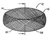
- FIG. 1is a perspective view of a first embodiment of the invention.
- FIG. 2is a side view of the embodiment of FIG. 1 .
- FIG. 3is a top view of the embodiment of FIG. 1 .
- FIG. 4is a perspective view of an embodiment of the invention having an elongate fill opening.
- FIG. 5is a perspective view of an embodiment of the invention as it may appear when used to replace a spinal disc.
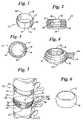
- FIG. 6is a perspective view of an embodiment of the invention wherein the band is a molded material.
- FIG. 7is a side view of an embodiment of the invention shown in the reduced state within a storage/delivery tool.
- FIG. 8is a side view of the embodiment shown in FIG. 7 wherein the inventive band is being removed from the storage/delivery tool.
- FIG. 9is a perspective view of an embodiment of the invention wherein the inventive band has a woven, double walled configuration.
- FIG. 10is a perspective cut away view of the embodiment shown in FIG. 9 .
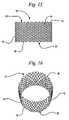
- FIG. 11is a perspective view of the embodiment of the invention shown in FIG. 9 wherein the inventive band further includes latitudinally oriented support bands.
- FIG. 12is a perspective cut away view of the embodiment shown in FIG. 11 .
- FIG. 13is a perspective view of the embodiment of the invention shown in FIG. 11 wherein the inventive band further includes longitudinally oriented support bands.
- FIG. 14is a perspective cut away view of the embodiment shown in FIG. 13 .
- FIG. 15is a side view of an embodiment of the invention wherein the inventive band has a single walled configuration.
- FIG. 16is a perspective view of an embodiment of the invention.
- FIG. 17is a top down view of an embodiment of the invention.
- FIG. 18is a side view of the embodiment of the invention shown in FIG. 15 wherein the inventive band is shown is a partially reduced state.
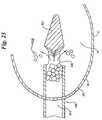
- FIG. 19is a perspective view of a graft insertion tool suitable for use with the inventive band.
- FIG. 20is a side view of the tool shown in FIG. 19 .
- FIG. 21is a top down view of the tool of FIG. 19 .
- FIG. 22is a side view of the tool of FIG. 19 seen dislocating the fibers of an embodiment of the inventive band.
- FIG. 23is a top down cut away view of a tool similar to the tool of FIG. 19 as may be seen during graft insertion.
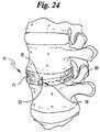
- FIG. 24is a perspective view of a portion of a spine wherein an embodiment of the invention is shown in place.
- FIG. 25is a cross-sectional view of a spinal body which includes an embodiment of the invention therein.
- FIG. 26is a close-up cut away view of a portion of the embodiment shown in FIG. 25 .
- FIG. 27is a cross sectional view of a spinal segment which includes an embodiments of the invention being positioned thereabout.
- FIG. 28is a perspective view of the spinal segment shown in FIG. 27 , wherein the embodiment of the invention is shown secured thereto.
- FIG. 29is a frontal view of a spinal segment shown in cross-section.
- FIG. 30is a frontal view of a spinal segment shown in cross-section, that includes an embodiment of the invention therewith.
- This inventionmay be characterized as an improvement of the inventor's inventions described in U.S. Pat. Nos. 5,571,189 and 5,549,679, the disclosures of which are incorporated herein by reference.
- FIGS. 1–3illustrates an embodiment of the inventive implant 10 which consists of a sidewall band 12 , which may be characterized as being substantially tubular or ring like in shape.
- the band 12is circular, however other elliptical shapes and other geometric shapes may also be used.
- the band 12is pliable and malleable before its interior space 14 (not shown in FIG. 2 ) is filled with the contents to be described. While in this initial condition, the band 12 may be passed, in a collapsed state, through a relatively small tube or portal, such as recited in U.S. Pat. Nos. 5,571,189 and 5,549,679, the entire contents of both references being incorporated herein by reference. This feature is important because access to the intervertebral disc is limited by anatomy and therefore safety considerations direct us to use the smallest possible portal of entry.
- the band 12may be constructed in a variety of ways.
- the band material 16may be etched, woven or braided material such as a weave of NITINOL fibers, or a form-molded material such as shown in FIG. 6 .
- the material or fabric 16may be fluid impermeable or may be provided with a density that will allow ingress and egress of fluids and solutions and will allow the ingrowth and through-growth of blood vessels and fibrous tissue and bony trabeculae. Where the material 16 is provided with such a porous construction, pores or weave gaps are preferably tight enough to retain small particles of enclosed fill material, such as ground up bone graft, other tissues or solid pieces of bone inducing material such as hydroxyapatite or other biocompatible materials known to promote bone formation.
- the pores or openings 18 of the fabricwill have a diameter of about 0.25 mm to about 5.0 mm. The size is selected to allow tissue ingrowth while containing the material packed into the bag.
- the material 16 of the inventionmust be flexible enough to allow it to be collapsed and inserted into an opening smaller than the expanded band size.
- the band 12is sufficiently flexible so that it may be positioned into a holding chamber 50 of a storage tube or delivery device 52 .
- the bandmay be compacted into a substantially smaller configuration than the band is capable of attaining when packed with graft material.
- the delivery deviceis sized such that the device 52 may be inserted into a surgical opening wherein the band 12 is drawn or pushed by plunger 56 out of the chamber 50 , as indicated by the direction of the arrow 54 as shown in FIG. 8 .
- the band 12may be used to repair and/or replace a vertebral disc 23 as may be seen in FIG. 5 wherein the band is placed between adjacent vertebral bodies 24 .
- the band 12may be inserted into a small opening in the annulus 21 of the disc 23 and filled from within the disc.
- the band 12may be inserted within a hollowed region of a vertebra 24 to provide support thereto, or may be utilized to replace an entire vertebral body 24 .
- the fill material used in conjunction with the band 12is preferably minimally elastic if at all.
- the fabric band 12may be formed from a polymeric material to which a plurality of perforations are formed or added. It need not be woven and may be molded, such as the embodiment shown in FIG. 6 , or otherwise formed as is well known in the art. The preferred material may provide the ability to tailor bioabsorbance rates. Any suture-type material used medically may be used to form the band 12 .
- the band 12may be formed of plastic or even metal.
- the band 12could be formed from a solid material.
- the band 12may be partially or totally absorbable, metal, plastic, woven, solid, film or an extruded balloon.
- the material 16is light, biocompatible, flexible and easily handled, but is also very strong in terms of resisting tension, and thus unlikely to rip or tear during insertion and expansion.
- the band 12expands to a predetermined shape, and in doing so, it fills a previously excavated space 20 between the vertebral bodies and/or within a vertebral body, such as may be seen in FIG. 5 . This filling results in the separation of the vertebral bodies 24 and results in the stabilization of the spinal motion segment, indicated generally at 22 .
- the band 12may be characterized as having two ends 30 and 32 .
- One or both ends 30 and 32may be open as defined by the band 12 .
- the openings 30 and 32are characterized as being less than the diameter of the surrounding vertebral bone, thus assuring containment of the graft material within the confines of the interior 14 of the band 12 .
- the material 16 which covers one or more of the openingsis porous to allow for bone growth therethrough such as has been described above.
- the band 12may be equipped with a fill opening 26 .
- the fill opening 26must be large enough to accommodate passage of fill material as well as the means of placing fill material into the interior space 14 of the band 12 .
- a device which may be suitable for passing through the fill opening 26 for insertion of fill materialis described in co-pending U.S. patent application Ser. No. 09/608,079 as discussed above.
- the opening 26includes a means of preventing passage of fill material out of the interior space 14 .
- the opening 26includes an elongate passage 28 which may be tied off or otherwise sealed subsequent to insertion of the fill material.
- the fill materialwill push against the vertebral surfaces 40 which are adjacent to the top 30 and bottom 32 of the band 12 .
- the band 12 in combination with the vertebral surfaces 40will contain the fill material within the interior space 14 .
- the fibersmay be composed of a variety of materials as previously discussed.
- the band 12may be constructed from one or more metal fibers such as, for example, NITINOL fibers 58 , which have been woven or braided together into the desired band shape.
- a shape-memory materialsuch as NITINOL, or a material such as steel, titanium or other metal, provides the band with sufficient mechanical strength to resist stretching or expansion as a result of the build up of graft material in the interior 14 .
- shape-memory materialsallow the band to be collapsed prior to insertion, such as may be seen in FIGS. 7 and 8 yet which will tend to reacquire its original shape once implanted.
- FIGS. 9–18depict a wide variety of band configurations.
- the band 12may be characterized as a double walled band or a loop of material folded back upon itself.
- Such a double walled configurationmay be seen as having a inner wall 60 which is continuous with the outer wall 62 and defining a toroid shaped space 63 therebetween as seen in FIGS. 10 and 12 .
- the toroidal shaped space 63may be filled, in whole or in part with pharmaceuticals for drug delivery to the implantation site.
- the toroid space 63may also be filled, subsequent to implantation into a vertebral body with a biocompatible cement or other material for providing the band 12 with additional support.
- the double walled constructionmay provide the band 12 with increased strength to provide additional mechanical support for the graft material contained in the interior 14 .
- the double walled constructionmay be configured to allow the various openings 18 of the respective walls 60 and 62 to partially overlap.
- the fibers 58 of one wallfor example inner wall 60
- the openings 18 of the other wallfor example outer wall 62
- a band 12 having a double walled constructionmay not require any more fibers 58 than a single walled band such as may be seen in FIGS. 15–18 .
- a double walled band 12may also include one or more latitudinally disposed support members such as members 64 and 66 shown.
- the individual support members 64 and 66may be positioned in any manner around the circumference of the band 12 .
- the members 64 and 66are respectively disposed the first or top opening 30 and the second or bottom opening 32 .
- the members 64 and 66are located between the inner wall 60 and outer wall 62 .
- the members 64 and 66may be used to support the material 16 of the band by weaving the fibers 58 about the members 64 and 66 , such as may best be seen in FIG. 12 .
- the members 64 and 66may be constructed from the same or different material as fibers 58 .
- the members 64 and 66may be one or more wires or fibers woven or braided together and oriented in the latitudinal orientation shown.
- one or more fibersmay be equatorially oriented, or may be otherwise positioned anywhere around the circumference of the band 12 .
- the bandmay also include one or more longitudinally oriented members 68 such as may be seen in the embodiment shown in FIGS. 13 and 14 .
- the longitudinal members 68vertically cross the band 12 to join the latitudinal members 64 and 66 .
- the longitudinal members 68are oriented substantially perpendicular to the latitudinal members 64 and 66 .
- the longitudinal members 68provide the band with compression support relative to the surrounding vertebra.
- the members 68may be woven into the fibers 58 or may be independent of the band's woven configuration.
- the various membersmay act as a frame work which supports the woven fibers 58 of the band 12 .
- the longitudinal members 68may be constructed out of any suitable material. Such material may be different from or the same as the fibers 58 . Additionally, the members 68 may be characterized as one or more fibers 58 oriented in the longitudinal direction shown.
- the band 12may be provided with only a single wall construction as opposed to the double walled construction previously described.
- the single wall 70is not a continuous overlapping loop of material such as may be seen in FIGS. 9 and 10
- the single walled band 12 shown in FIG. 15may have openings 30 and 32 which have fairly jagged or non-uniform edges 72 .
- the material 16 of the band 12may not necessarily be of sufficient hardness to penetrate the surrounding vertebral bone, the non-uniform nature of the edges 72 of the band 12 , provides band 12 with surfaces which may tend to more readily engage the surfaces of the surrounding vertebral bone, thereby preventing the band 12 from shifting or otherwise moving during the graft injection process or thereafter.
- the single walled band 12may be configured to have an essentially cylindrical shape.
- the cylindrical shapemay be compressed into an elongated band such as may be seen in FIGS. 7 an 8 prior to insertion into the body.
- the band 12may be configured to include other shapes, notably the rounded configuration shown in FIG. 17 , after the band 12 is inserted into a vertebral body.
- FIG. 18the malleability of a single walled band is illustrated.
- the band 12may be significantly distorted, collapsed or otherwise manipulated in order to collapse the band into a reduced configuration such as may be seen in FIGS. 7 and 8 .
- the present inventionmay be distorted in either or both the radial and longitudinal directions while retaining its ability to expand subsequent to insertion into the spinal area.
- the band 12is shown with a fill insertion tool 100 being inserted into the interior 14 of the band 12 by passing through one of the spaces or pores 18 .
- the shape of the tool 100 as may best be seen in FIGS. 19–21is essentially an elongate shaft 104 having a tapered or pointed distal end 102 .
- FIGS. 19–21an example of a fill insertion tool which is suitable for use in the various embodiments of the invention is illustrated.
- the tool 100is further disclosed in a co-pending U.S. patent application Ser. No. 09/738,726 filed Dec. 15, 2000 and entitled Tool to Direct Bone Replacement Material, to Kuslich et al., and is a continuation in part application of U.S. patent application Ser. No. 09/608,079 the entire contents of both being incorporated herein by reference.
- the tapered distal end 102 of the tool 100is sized to enlarge the opening 18 to allow passage of the tool 100 into the interior 14 by pushing aside the various fibers 58 as may best be seen in FIG. 22 .
- the fibers 58are disposed to open the pore 18 from its nominal diameter of about 0.25 mm to about 5 mm to an enlarged opening sufficient to allow passage of a portion of the shaft 104 therethrough.
- the extent of tool penetration into the band interior 14must be sufficient to allow the side opening 106 to be fully contained within the band interior 14 .
- the tool 100may include more than 1 side opening 106 .
- the side opening 106allows insertion of the bone graft or other types of fill material 108 into the band interior 12 .
- the tool 100may include a piston plunger or other means (not shown) for pushing fill material 108 from within the shaft 104 , through the side opening 106 and into the band interior 14 .
- the internal diameter of the shaft 104may be about 1.5 mm to 5 mm and is preferably approximately 2.5 mm in diameter.
- the length of the side opening 106is preferably between about 11 ⁇ 2 to 3 times the internal diameter of the shaft 104 .
- the distal end 102 of the tool 100is preferably angled to direct the flow and to break down any material that has packed back into more discrete pieces.
- each member 65extends about the mid-portion 71 of the band 12 and includes ends 73 and 75 that extend outward from one of the pores 18 where they may be pulled together and secured or tied to one another in the manner shown.
- the ends 73 and 75may be cinched together in order to constrict the mid-portion of the band 12 so that the band 12 takes on a concave shape, such as is shown.
- the concave shapemay provide greater support and flexibility to the surrounding spinal bodies and to the spine itself.
- ends 73 and 75are pulled together and secured, not only is the band provided with a concave shape, but any fill material positioned therein is pushed together for more effective engagement with surrounding tissue as well as with itself and the band 12 .
- the band 12may include portions 81 and 83 , where electrical leads 91 and 93 may be readily attached, such as are shown in FIG. 25 .
- Leads 91 and 93are in electrical communication with an electrical power source 95 which provides sufficient current to stimulate bone growth through and adjacent to the band 12 .
- the leads 91 and 93may be inserted through pores 18 , as previously shown and described, to directly stimulate the fill material 108 .
- the portions 81 and 83may be part of a electrically conductive member 85 which is disposed within the walls 60 and 62 of the band 12 , such as is shown in FIG. 26 .
- the entire band 12is electrically conductive, In yet another embodiment at least a portion of one or both walls 60 and 62 are electrically conductive and/or electrically insulated.
- the implant 10may be characterized as a linear member or members 200 which is disposed about a vertebral disc 23 in a manner such as is shown in FIG. 27 .
- the member 200may be a one or more of a combination of strands, threads, fibers, cords or other substantially linear portions of material which include a first end 202 and a second end 204 that are capable of being tied or otherwise secured together.
- the member 200has a height sufficient to cover the entire exposed surface of the disc 23 .
- member 200Some examples of materials which are suitable for use as member 200 or in its construction include, but are not limited to: Secure Strand available from Smith & Nephew Inc., THE LOOP.TM., available from Spineology Inc., and Songer Cable from Medtronic Inc.
- the member 200may be constructed of the same material 16 as the previously described embodiments of the invention shown in FIGS. 1–26 , and include a plurality of pores or openings 18 .
- the member 200may be further cinched or otherwise tightened about the disc 23 as is shown in FIGS. 29 and 30 .
- the disc 23is compressed in order to invaginate the annulus 21 toward its center thereby tightening the annulus fibers. Such tightening will stabilize the spinal motion segment 22 and thereby stiffen that portion of the spine.
- FIG. 29the annulus 21 of a disk 23 is shown within a spinal motion segment 22 prior to the securement and tightening of member 200 thereabout. It is shown that the annulus 21 of the disk 23 has a predetermined height 206 and a predetermined circumference 208 .
- the circumferenceis reduced as indicated at reference numeral 208 ′ while the height of the disk is made greater as is indicated at reference numeral 206 ′.
- the member 200By securing the ends 202 and 204 of the member 200 about the disc, the member 200 forms a substantially continuous band similar to that previously described.
- the member 200When secured about a disc the member 200 preferably has a substantially concave appearance, relative to the surrounding spinal bodies, such as is shown in FIG. 28 .
- the disc 23When secured about the disc 23 , the disc 23 may be further treated with additional therapeutic agents, including fill material via the pores or openings 18 , in the manner previously described in relation to the embodiments shown in FIGS. 1–26 .
- any dependent claim which followsshould be taken as alternatively written in a multiple dependent form from all prior claims which possess all antecedents referenced in such dependent claim if such multiple dependent format is an accepted format within the jurisdiction (e.g. each claim depending directly from claim 1 should be alternatively taken as depending from all previous claims).
- each claim depending directly from claim 1should be alternatively taken as depending from all previous claims.
- the following dependent claimsshould each be also taken as alternatively written in each singly dependent claim format which creates a dependency from a prior antecedent-possessing claim other than the specific claim listed in such dependent claim below.
Landscapes
- Health & Medical Sciences (AREA)
- Engineering & Computer Science (AREA)
- Biomedical Technology (AREA)
- Orthopedic Medicine & Surgery (AREA)
- Transplantation (AREA)
- Neurology (AREA)
- Heart & Thoracic Surgery (AREA)
- Veterinary Medicine (AREA)
- Oral & Maxillofacial Surgery (AREA)
- Cardiology (AREA)
- Public Health (AREA)
- Vascular Medicine (AREA)
- Life Sciences & Earth Sciences (AREA)
- Animal Behavior & Ethology (AREA)
- General Health & Medical Sciences (AREA)
- Physical Education & Sports Medicine (AREA)
- Chemical & Material Sciences (AREA)
- Dispersion Chemistry (AREA)
- Prostheses (AREA)
- Materials For Medical Uses (AREA)
- Electrotherapy Devices (AREA)
Abstract
Description
Claims (5)
Priority Applications (5)
| Application Number | Priority Date | Filing Date | Title |
|---|---|---|---|
| US11/447,615US7220282B2 (en) | 2000-12-15 | 2006-06-06 | Annulus-reinforcing band |
| US11/752,059US20080045952A1 (en) | 2000-12-15 | 2007-05-22 | Annulus-reinforcing band |
| US12/894,106US8747475B2 (en) | 2000-12-15 | 2010-09-29 | Annulus-reinforcing band |
| US12/983,079US20110245924A1 (en) | 2000-12-15 | 2010-12-31 | Annulus-Reinforcing Band |
| US14/299,951US20140288656A1 (en) | 2000-12-15 | 2014-06-09 | Annulus-reinforcing band |
Applications Claiming Priority (4)
| Application Number | Priority Date | Filing Date | Title |
|---|---|---|---|
| US25601400P | 2000-12-15 | 2000-12-15 | |
| US10/022,048US6712853B2 (en) | 2000-12-15 | 2001-12-17 | Annulus-reinforcing band |
| US10/812,345US7056345B2 (en) | 2000-12-15 | 2004-03-29 | Annulus-reinforcing band |
| US11/447,615US7220282B2 (en) | 2000-12-15 | 2006-06-06 | Annulus-reinforcing band |
Related Parent Applications (1)
| Application Number | Title | Priority Date | Filing Date |
|---|---|---|---|
| US10/812,345ContinuationUS7056345B2 (en) | 2000-12-15 | 2004-03-29 | Annulus-reinforcing band |
Related Child Applications (1)
| Application Number | Title | Priority Date | Filing Date |
|---|---|---|---|
| US11/752,059ContinuationUS20080045952A1 (en) | 2000-12-15 | 2007-05-22 | Annulus-reinforcing band |
Publications (2)
| Publication Number | Publication Date |
|---|---|
| US20070016300A1 US20070016300A1 (en) | 2007-01-18 |
| US7220282B2true US7220282B2 (en) | 2007-05-22 |
Family
ID=22970766
Family Applications (7)
| Application Number | Title | Priority Date | Filing Date |
|---|---|---|---|
| US10/022,048Expired - LifetimeUS6712853B2 (en) | 2000-12-15 | 2001-12-17 | Annulus-reinforcing band |
| US10/812,345Expired - LifetimeUS7056345B2 (en) | 2000-12-15 | 2004-03-29 | Annulus-reinforcing band |
| US11/447,615Expired - LifetimeUS7220282B2 (en) | 2000-12-15 | 2006-06-06 | Annulus-reinforcing band |
| US11/752,059AbandonedUS20080045952A1 (en) | 2000-12-15 | 2007-05-22 | Annulus-reinforcing band |
| US12/894,106Expired - LifetimeUS8747475B2 (en) | 2000-12-15 | 2010-09-29 | Annulus-reinforcing band |
| US12/983,079AbandonedUS20110245924A1 (en) | 2000-12-15 | 2010-12-31 | Annulus-Reinforcing Band |
| US14/299,951AbandonedUS20140288656A1 (en) | 2000-12-15 | 2014-06-09 | Annulus-reinforcing band |
Family Applications Before (2)
| Application Number | Title | Priority Date | Filing Date |
|---|---|---|---|
| US10/022,048Expired - LifetimeUS6712853B2 (en) | 2000-12-15 | 2001-12-17 | Annulus-reinforcing band |
| US10/812,345Expired - LifetimeUS7056345B2 (en) | 2000-12-15 | 2004-03-29 | Annulus-reinforcing band |
Family Applications After (4)
| Application Number | Title | Priority Date | Filing Date |
|---|---|---|---|
| US11/752,059AbandonedUS20080045952A1 (en) | 2000-12-15 | 2007-05-22 | Annulus-reinforcing band |
| US12/894,106Expired - LifetimeUS8747475B2 (en) | 2000-12-15 | 2010-09-29 | Annulus-reinforcing band |
| US12/983,079AbandonedUS20110245924A1 (en) | 2000-12-15 | 2010-12-31 | Annulus-Reinforcing Band |
| US14/299,951AbandonedUS20140288656A1 (en) | 2000-12-15 | 2014-06-09 | Annulus-reinforcing band |
Country Status (12)
| Country | Link |
|---|---|
| US (7) | US6712853B2 (en) |
| EP (1) | EP1341489B1 (en) |
| JP (2) | JP4202134B2 (en) |
| KR (1) | KR100631787B1 (en) |
| AT (1) | ATE387163T1 (en) |
| AU (2) | AU2002246690B2 (en) |
| CA (2) | CA2429149C (en) |
| DE (1) | DE60133033T2 (en) |
| HU (1) | HUP0302127A2 (en) |
| MX (1) | MXPA03005362A (en) |
| NZ (1) | NZ525999A (en) |
| WO (1) | WO2002056802A1 (en) |
Cited By (83)
| Publication number | Priority date | Publication date | Assignee | Title |
|---|---|---|---|---|
| US20060064171A1 (en)* | 2000-08-30 | 2006-03-23 | Trieu Hai H | Methods for forming and retaining intervertebral disc implants |
| US20070050033A1 (en)* | 2005-09-01 | 2007-03-01 | Reo Michael L | Prosthetic intervertebral discs |
| US20070050032A1 (en)* | 2005-09-01 | 2007-03-01 | Spinal Kinetics, Inc. | Prosthetic intervertebral discs |
| US20070083200A1 (en)* | 2005-09-23 | 2007-04-12 | Gittings Darin C | Spinal stabilization systems and methods |
| US20070088436A1 (en)* | 2005-09-29 | 2007-04-19 | Matthew Parsons | Methods and devices for stenting or tamping a fractured vertebral body |
| US20070093899A1 (en)* | 2005-09-28 | 2007-04-26 | Christof Dutoit | Apparatus and methods for treating bone |
| US20070098756A1 (en)* | 2005-11-01 | 2007-05-03 | Keyvan Behnam | Bone Matrix Compositions and Methods |
| US20070154563A1 (en)* | 2003-12-31 | 2007-07-05 | Keyvan Behnam | Bone matrix compositions and methods |
| US20070168033A1 (en)* | 2003-08-01 | 2007-07-19 | Kim Daniel H | Prosthetic intervertebral discs having substantially rigid end plates and fibers between those end plates |
| US20070198025A1 (en)* | 2000-08-30 | 2007-08-23 | Trieu Hai H | Method and apparatus for delivering an intervertebral disc implant |
| US20070231788A1 (en)* | 2003-12-31 | 2007-10-04 | Keyvan Behnam | Method for In Vitro Assay of Demineralized Bone Matrix |
| US20070299523A1 (en)* | 2006-06-08 | 2007-12-27 | Francis Pflum | Sac for use in spinal surgery |
| US20080027546A1 (en)* | 2006-07-25 | 2008-01-31 | Semler Eric J | Packed demineralized cancellous tissue forms for disc nucleus augmentation, restoration, or replacement and methods of implantation |
| US20080077244A1 (en)* | 2006-09-26 | 2008-03-27 | Robinson Janine C | Prosthetic intervertebral discs having cast end plates and methods for making and using them |
| US20080082169A1 (en)* | 2006-09-28 | 2008-04-03 | Gittings Darin C | Tool systems for implanting prosthetic intervertebral discs |
| US20080099785A1 (en)* | 2006-09-07 | 2008-05-01 | Amberwave Systems Coporation | Defect Reduction Using Aspect Ratio Trapping |
| US20090087471A1 (en)* | 2007-06-15 | 2009-04-02 | Shimp Lawrence A | Method of treating tissue |
| US7520900B2 (en) | 2000-08-30 | 2009-04-21 | Warsaw Orthopedic, Inc. | Intervertebral disc nucleus implants and methods |
| US20090125110A1 (en)* | 2002-11-05 | 2009-05-14 | Kuslich Stephen D | Semi-biological intervertebral disc replacement system |
| US20090130173A1 (en)* | 2007-06-15 | 2009-05-21 | Keyvan Behnam | Bone matrix compositions and methods |
| US20090149958A1 (en)* | 2007-11-01 | 2009-06-11 | Ann Prewett | Structurally reinforced spinal nucleus implants |
| US20090155378A1 (en)* | 2003-12-31 | 2009-06-18 | Keyvan Behnam | Osteoinductive demineralized cancellous bone |
| US20090157087A1 (en)* | 2007-07-10 | 2009-06-18 | Guobao Wei | Delivery system attachment |
| US20090220605A1 (en)* | 2007-06-15 | 2009-09-03 | Osteotech | Bone matrix compositions having nanoscale textured surfaces |
| US20090226523A1 (en)* | 2007-10-19 | 2009-09-10 | Keyvan Behnam | Demineralized bone matrix compositions and methods |
| WO2009120248A1 (en) | 2008-03-28 | 2009-10-01 | Osteotech, Inc. | Delivery system attachment |
| US20090242081A1 (en)* | 2008-03-26 | 2009-10-01 | Richard Bauer | Aluminum Treatment Composition |
| US7618461B2 (en) | 2000-08-30 | 2009-11-17 | Warsaw Orthopedic, Inc. | Composite intervertebral disc implants and methods for forming the same |
| US20100076497A1 (en)* | 2004-06-10 | 2010-03-25 | Zwirkoski Paul A | Device and Method for Securing a Fastener |
| US20100204699A1 (en)* | 2009-02-12 | 2010-08-12 | Guobao Wei | Delivery system cartridge |
| US20100256766A1 (en)* | 2009-04-07 | 2010-10-07 | Hibri Nadi S | Percutaneous Implantable Nuclear Prosthesis |
| US20100268343A1 (en)* | 2009-04-16 | 2010-10-21 | Warsaw Orthopedic, Inc. | Vertebral endplate connection implant and method |
| US7879103B2 (en) | 2005-04-15 | 2011-02-01 | Musculoskeletal Transplant Foundation | Vertebral disc repair |
| US20110054532A1 (en)* | 2007-07-03 | 2011-03-03 | Alexandre De Moura | Interspinous mesh |
| US20110054408A1 (en)* | 2007-07-10 | 2011-03-03 | Guobao Wei | Delivery systems, devices, tools, and methods of use |
| US7909873B2 (en) | 2006-12-15 | 2011-03-22 | Soteira, Inc. | Delivery apparatus and methods for vertebrostenting |
| US20110230970A1 (en)* | 2010-03-16 | 2011-09-22 | Pinnacle Spine Group, Llc | Intervertebral implants and graft delivery systems and methods |
| US8066750B2 (en) | 2006-10-06 | 2011-11-29 | Warsaw Orthopedic, Inc | Port structures for non-rigid bone plates |
| US8287538B2 (en) | 2008-01-14 | 2012-10-16 | Conventus Orthopaedics, Inc. | Apparatus and methods for fracture repair |
| US8317808B2 (en) | 2008-02-18 | 2012-11-27 | Covidien Lp | Device and method for rolling and inserting a prosthetic patch into a body cavity |
| WO2013023096A1 (en)* | 2011-08-09 | 2013-02-14 | Neuropro Technologies, Inc. | Bone fusion device, system and method |
| US8403987B2 (en) | 2006-09-27 | 2013-03-26 | Spinal Kinetics Inc. | Prosthetic intervertebral discs having compressible core elements bounded by fiber-containing membranes |
| US20130144391A1 (en)* | 2010-07-15 | 2013-06-06 | Nlt Spine Ltd | Surgical systems and methods for implanting deflectable implants |
| US8597360B2 (en) | 2004-11-03 | 2013-12-03 | Neuropro Technologies, Inc. | Bone fusion device |
| US8753359B2 (en) | 2008-02-18 | 2014-06-17 | Covidien Lp | Device and method for deploying and attaching an implant to a biological tissue |
| US8758373B2 (en) | 2008-02-18 | 2014-06-24 | Covidien Lp | Means and method for reversibly connecting a patch to a patch deployment device |
| US8808314B2 (en) | 2008-02-18 | 2014-08-19 | Covidien Lp | Device and method for deploying and attaching an implant to a biological tissue |
| US8888811B2 (en) | 2008-10-20 | 2014-11-18 | Covidien Lp | Device and method for attaching an implant to biological tissue |
| US8906045B2 (en) | 2009-08-17 | 2014-12-09 | Covidien Lp | Articulating patch deployment device and method of use |
| US8906022B2 (en) | 2010-03-08 | 2014-12-09 | Conventus Orthopaedics, Inc. | Apparatus and methods for securing a bone implant |
| US8961518B2 (en) | 2010-01-20 | 2015-02-24 | Conventus Orthopaedics, Inc. | Apparatus and methods for bone access and cavity preparation |
| US9034002B2 (en) | 2008-02-18 | 2015-05-19 | Covidien Lp | Lock bar spring and clip for implant deployment device |
| US9044235B2 (en) | 2008-02-18 | 2015-06-02 | Covidien Lp | Magnetic clip for implant deployment device |
| US9192397B2 (en) | 2006-12-15 | 2015-11-24 | Gmedelaware 2 Llc | Devices and methods for fracture reduction |
| US9289240B2 (en) | 2005-12-23 | 2016-03-22 | DePuy Synthes Products, Inc. | Flexible elongated chain implant and method of supporting body tissue with same |
| US9295479B2 (en) | 2013-03-14 | 2016-03-29 | Spinal Stabilization Technologies, Llc | Surgical device |
| US9301826B2 (en) | 2008-02-18 | 2016-04-05 | Covidien Lp | Lock bar spring and clip for implant deployment device |
| US9358123B2 (en) | 2011-08-09 | 2016-06-07 | Neuropro Spinal Jaxx, Inc. | Bone fusion device, apparatus and method |
| US9380932B1 (en) | 2011-11-02 | 2016-07-05 | Pinnacle Spine Group, Llc | Retractor devices for minimally invasive access to the spine |
| US9393057B2 (en) | 2013-10-08 | 2016-07-19 | Pioneer Surgical Technology, Inc. | Surgical system and method |
| US9393093B2 (en) | 2008-02-18 | 2016-07-19 | Covidien Lp | Clip for implant deployment device |
| US9393002B2 (en) | 2008-02-18 | 2016-07-19 | Covidien Lp | Clip for implant deployment device |
| US9398944B2 (en) | 2008-02-18 | 2016-07-26 | Covidien Lp | Lock bar spring and clip for implant deployment device |
| US9480485B2 (en) | 2006-12-15 | 2016-11-01 | Globus Medical, Inc. | Devices and methods for vertebrostenting |
| US9545321B2 (en) | 2013-03-14 | 2017-01-17 | Spinal Stabilization Technologies Llc | Prosthetic spinal disk nucleus |
| US9668875B2 (en) | 1999-03-07 | 2017-06-06 | Nuvasive, Inc. | Method and apparatus for computerized surgery |
| US9730739B2 (en) | 2010-01-15 | 2017-08-15 | Conventus Orthopaedics, Inc. | Rotary-rigid orthopaedic rod |
| US9833240B2 (en) | 2008-02-18 | 2017-12-05 | Covidien Lp | Lock bar spring and clip for implant deployment device |
| US9999424B2 (en) | 2009-08-17 | 2018-06-19 | Covidien Lp | Means and method for reversibly connecting an implant to a deployment device |
| US10022132B2 (en) | 2013-12-12 | 2018-07-17 | Conventus Orthopaedics, Inc. | Tissue displacement tools and methods |
| US10070970B2 (en) | 2013-03-14 | 2018-09-11 | Pinnacle Spine Group, Llc | Interbody implants and graft delivery systems |
| US10143560B2 (en) | 2006-06-08 | 2018-12-04 | Francis Pflum | Sac for use in spinal surgery |
| US10314714B2 (en) | 2014-11-04 | 2019-06-11 | Spinal Stabilization Technologies Llc | Percutaneous implantable nuclear prosthesis |
| US10441336B2 (en) | 2017-06-14 | 2019-10-15 | Osteoagra Llc | Stabilization of vertebral bodies with bone particle slurry |
| US10575967B2 (en) | 2015-09-01 | 2020-03-03 | Spinal Stabilization Technologies Llc | Implantable nuclear prosthesis |
| US10617530B2 (en) | 2011-07-14 | 2020-04-14 | Seaspine, Inc. | Laterally deflectable implant |
| US10918426B2 (en) | 2017-07-04 | 2021-02-16 | Conventus Orthopaedics, Inc. | Apparatus and methods for treatment of a bone |
| US11213402B2 (en) | 2017-01-11 | 2022-01-04 | Loubert S. Suddaby | Endoscopically implantable inflatable interbody fusion device |
| US11596419B2 (en) | 2017-03-09 | 2023-03-07 | Flower Orthopedics Corporation | Plating depth gauge and countersink instrument |
| US11633287B2 (en) | 2014-11-04 | 2023-04-25 | Spinal Stabilization Technologies Llc | Percutaneous implantable nuclear prosthesis |
| US11744710B2 (en) | 2018-09-04 | 2023-09-05 | Spinal Stabilization Technologies Llc | Implantable nuclear prosthesis, kits, and related methods |
| WO2024119139A1 (en)* | 2022-12-01 | 2024-06-06 | Percheron Spine, Llc | Spinal implant and delivery system |
| US12102367B2 (en) | 2017-06-14 | 2024-10-01 | Osteoagra Llc | Method, composition, and apparatus for stabilization of vertebral bodies |
Families Citing this family (331)
| Publication number | Priority date | Publication date | Assignee | Title |
|---|---|---|---|---|
| EP0873145A2 (en) | 1996-11-15 | 1998-10-28 | Advanced Bio Surfaces, Inc. | Biomaterial system for in situ tissue repair |
| US7273497B2 (en) | 1999-05-28 | 2007-09-25 | Anova Corp. | Methods for treating a defect in the annulus fibrosis |
| US20060247665A1 (en) | 1999-05-28 | 2006-11-02 | Ferree Bret A | Methods and apparatus for treating disc herniation and preventing the extrusion of interbody bone graft |
| US6969404B2 (en)* | 1999-10-08 | 2005-11-29 | Ferree Bret A | Annulus fibrosis augmentation methods and apparatus |
| US20070038231A1 (en) | 1999-05-28 | 2007-02-15 | Ferree Bret A | Methods and apparatus for treating disc herniation and preventing the extrusion of interbody bone graft |
| US8323341B2 (en) | 2007-09-07 | 2012-12-04 | Intrinsic Therapeutics, Inc. | Impaction grafting for vertebral fusion |
| US20040010317A1 (en)* | 1999-08-18 | 2004-01-15 | Gregory Lambrecht | Devices and method for augmenting a vertebral disc |
| US6936072B2 (en)* | 1999-08-18 | 2005-08-30 | Intrinsic Therapeutics, Inc. | Encapsulated intervertebral disc prosthesis and methods of manufacture |
| US7998213B2 (en) | 1999-08-18 | 2011-08-16 | Intrinsic Therapeutics, Inc. | Intervertebral disc herniation repair |
| US6821276B2 (en) | 1999-08-18 | 2004-11-23 | Intrinsic Therapeutics, Inc. | Intervertebral diagnostic and manipulation device |
| US7972337B2 (en) | 2005-12-28 | 2011-07-05 | Intrinsic Therapeutics, Inc. | Devices and methods for bone anchoring |
| US7717961B2 (en) | 1999-08-18 | 2010-05-18 | Intrinsic Therapeutics, Inc. | Apparatus delivery in an intervertebral disc |
| CA2425951C (en)* | 1999-08-18 | 2008-09-16 | Intrinsic Therapeutics, Inc. | Devices and method for nucleus pulposus augmentation and retention |
| US7553329B2 (en)* | 1999-08-18 | 2009-06-30 | Intrinsic Therapeutics, Inc. | Stabilized intervertebral disc barrier |
| US7094258B2 (en) | 1999-08-18 | 2006-08-22 | Intrinsic Therapeutics, Inc. | Methods of reinforcing an annulus fibrosis |
| EP1624832A4 (en) | 1999-08-18 | 2008-12-24 | Intrinsic Therapeutics Inc | Devices and method for augmenting a vertebral disc nucleus |
| US6964674B1 (en)* | 1999-09-20 | 2005-11-15 | Nuvasive, Inc. | Annulotomy closure device |
| US20040186573A1 (en)* | 1999-10-08 | 2004-09-23 | Ferree Bret A. | Annulus fibrosis augmentation methods and apparatus |
| US7201774B2 (en)* | 1999-10-08 | 2007-04-10 | Ferree Bret A | Artificial intervertebral disc replacements incorporating reinforced wall sections |
| US20030040796A1 (en)* | 1999-10-08 | 2003-02-27 | Ferree Bret A. | Devices used to treat disc herniation and attachment mechanisms therefore |
| US8679180B2 (en)* | 1999-10-08 | 2014-03-25 | Anova Corporation | Devices used to treat disc herniation and attachment mechanisms therefore |
| US7052516B2 (en) | 1999-10-20 | 2006-05-30 | Anulex Technologies, Inc. | Spinal disc annulus reconstruction method and deformable spinal disc annulus stent |
| US8128698B2 (en) | 1999-10-20 | 2012-03-06 | Anulex Technologies, Inc. | Method and apparatus for the treatment of the intervertebral disc annulus |
| US20030153976A1 (en)* | 1999-10-20 | 2003-08-14 | Cauthen Joseph C. | Spinal disc annulus reconstruction method and spinal disc annulus stent |
| US7615076B2 (en) | 1999-10-20 | 2009-11-10 | Anulex Technologies, Inc. | Method and apparatus for the treatment of the intervertebral disc annulus |
| US7951201B2 (en) | 1999-10-20 | 2011-05-31 | Anulex Technologies, Inc. | Method and apparatus for the treatment of the intervertebral disc annulus |
| US8632590B2 (en) | 1999-10-20 | 2014-01-21 | Anulex Technologies, Inc. | Apparatus and methods for the treatment of the intervertebral disc |
| US6592625B2 (en) | 1999-10-20 | 2003-07-15 | Anulex Technologies, Inc. | Spinal disc annulus reconstruction method and spinal disc annulus stent |
| US7004970B2 (en) | 1999-10-20 | 2006-02-28 | Anulex Technologies, Inc. | Methods and devices for spinal disc annulus reconstruction and repair |
| US7935147B2 (en) | 1999-10-20 | 2011-05-03 | Anulex Technologies, Inc. | Method and apparatus for enhanced delivery of treatment device to the intervertebral disc annulus |
| US6805695B2 (en) | 2000-04-04 | 2004-10-19 | Spinalabs, Llc | Devices and methods for annular repair of intervertebral discs |
| GB0024898D0 (en)* | 2000-10-11 | 2000-11-22 | Ellis Dev Ltd | A connector |
| US6896692B2 (en) | 2000-12-14 | 2005-05-24 | Ensure Medical, Inc. | Plug with collet and apparatus and method for delivering such plugs |
| US6890343B2 (en) | 2000-12-14 | 2005-05-10 | Ensure Medical, Inc. | Plug with detachable guidewire element and methods for use |
| US8083768B2 (en) | 2000-12-14 | 2011-12-27 | Ensure Medical, Inc. | Vascular plug having composite construction |
| US6846319B2 (en) | 2000-12-14 | 2005-01-25 | Core Medical, Inc. | Devices for sealing openings through tissue and apparatus and methods for delivering them |
| US6623509B2 (en) | 2000-12-14 | 2003-09-23 | Core Medical, Inc. | Apparatus and methods for sealing vascular punctures |
| US20050209629A1 (en)* | 2001-04-19 | 2005-09-22 | Kerr Sean H | Resorbable containment device and process for making and using same |
| US6632235B2 (en) | 2001-04-19 | 2003-10-14 | Synthes (U.S.A.) | Inflatable device and method for reducing fractures in bone and in treating the spine |
| US8353932B2 (en) | 2005-09-30 | 2013-01-15 | Jackson Roger P | Polyaxial bone anchor assembly with one-piece closure, pressure insert and plastic elongate member |
| US7862587B2 (en) | 2004-02-27 | 2011-01-04 | Jackson Roger P | Dynamic stabilization assemblies, tool set and method |
| US8292926B2 (en) | 2005-09-30 | 2012-10-23 | Jackson Roger P | Dynamic stabilization connecting member with elastic core and outer sleeve |
| US10258382B2 (en) | 2007-01-18 | 2019-04-16 | Roger P. Jackson | Rod-cord dynamic connection assemblies with slidable bone anchor attachment members along the cord |
| US10729469B2 (en) | 2006-01-09 | 2020-08-04 | Roger P. Jackson | Flexible spinal stabilization assembly with spacer having off-axis core member |
| US20090234457A1 (en)* | 2001-06-29 | 2009-09-17 | The Regents Of The University Of California | Systems, devices and methods for treatment of intervertebral disorders |
| JP2003032089A (en)* | 2001-07-18 | 2003-01-31 | Matsushita Electric Ind Co Ltd | Microcomputer with built-in reset function |
| US6736815B2 (en)* | 2001-09-06 | 2004-05-18 | Core Medical, Inc. | Apparatus and methods for treating spinal discs |
| US20030055316A1 (en)* | 2001-09-19 | 2003-03-20 | Brannon James Kevin | Endoscopic bone debridement |
| US7267687B2 (en) | 2001-10-02 | 2007-09-11 | Rex Medical, L.P | Spinal implant and method of use |
| AU2002350026A1 (en)* | 2001-11-01 | 2003-05-12 | Lawrence M. Boyd | System and method for the pretreatment of the endplates of an intervertebral disc |
| US7004945B2 (en)* | 2001-11-01 | 2006-02-28 | Spinewave, Inc. | Devices and methods for the restoration of a spinal disc |
| GB2382028B (en)* | 2001-11-19 | 2006-11-01 | Aberdeen Orthopaedic Developme | Intervertebral disc prosthesis |
| US20030195630A1 (en)* | 2002-04-10 | 2003-10-16 | Ferree Bret A. | Disc augmentation using materials that expand in situ |
| US7223289B2 (en)* | 2002-04-16 | 2007-05-29 | Warsaw Orthopedic, Inc. | Annulus repair systems and techniques |
| EP2292151B1 (en)* | 2002-05-10 | 2014-08-27 | Covidien LP | Surgical stapling apparatus having a wound closure material applicator assembly |
| EP1515645B1 (en) | 2002-06-17 | 2006-08-16 | Tyco Healthcare Group Lp | Annular support structures |
| US6793678B2 (en) | 2002-06-27 | 2004-09-21 | Depuy Acromed, Inc. | Prosthetic intervertebral motion disc having dampening |
| EP1542626B1 (en) | 2002-08-15 | 2012-09-26 | Synthes GmbH | Controlled artificial intervertebral disc implant |
| CA2495404C (en)* | 2002-08-15 | 2011-05-03 | Justin K. Coppes | Intervertebral disc implant |
| CN100584294C (en)* | 2002-08-27 | 2010-01-27 | 华沙整形外科股份有限公司 | System for intravertebral reduction |
| US20040054414A1 (en) | 2002-09-18 | 2004-03-18 | Trieu Hai H. | Collagen-based materials and methods for augmenting intervertebral discs |
| US7744651B2 (en)* | 2002-09-18 | 2010-06-29 | Warsaw Orthopedic, Inc | Compositions and methods for treating intervertebral discs with collagen-based materials |
| ES2343951T3 (en)* | 2002-09-24 | 2010-08-13 | Bogomir Gorensek | STABILIZING DEVICE FOR INTERVERTEBRAL DISK AND METHODS FOR IT. |
| US7320686B2 (en)* | 2002-10-09 | 2008-01-22 | Depuy Acromed, Inc. | Device for distracting vertebrae and delivering a flowable material into a disc space |
| AU2003252848B2 (en)* | 2002-10-09 | 2007-07-05 | Depuy Acromed, Inc. | Device for distracting vertebrae and delivering a flowable material into a disc space |
| WO2004043271A1 (en)* | 2002-11-08 | 2004-05-27 | Sdgi Holdings, Inc. | Transpedicular intervertebral disk access methods and devices |
| JP2006515765A (en)* | 2002-11-15 | 2006-06-08 | エスディージーアイ・ホールディングス・インコーポレーテッド | Collagen-based materials and methods for treating synovial joints |
| AU2009200502C1 (en)* | 2002-11-19 | 2011-09-15 | Zimmer Technology, Inc. | Artifical spinal disc |
| US6733533B1 (en)* | 2002-11-19 | 2004-05-11 | Zimmer Technology, Inc. | Artificial spinal disc |
| US20040186471A1 (en)* | 2002-12-07 | 2004-09-23 | Sdgi Holdings, Inc. | Method and apparatus for intervertebral disc expansion |
| US7004971B2 (en)* | 2002-12-31 | 2006-02-28 | Depuy Acromed, Inc. | Annular nucleus pulposus replacement |
| AU2004212942A1 (en) | 2003-02-14 | 2004-09-02 | Depuy Spine, Inc. | In-situ formed intervertebral fusion device |
| ES2545328T3 (en) | 2003-03-14 | 2015-09-10 | Depuy Spine, Inc. | Bone cement hydraulic injection device in percutaneous vertebroplasty |
| US8066713B2 (en) | 2003-03-31 | 2011-11-29 | Depuy Spine, Inc. | Remotely-activated vertebroplasty injection device |
| US20040199256A1 (en)* | 2003-04-04 | 2004-10-07 | Chao-Jan Wang | Support device for supporting between spinal vertebrae |
| US7621918B2 (en) | 2004-11-23 | 2009-11-24 | Jackson Roger P | Spinal fixation tool set and method |
| US6986771B2 (en) | 2003-05-23 | 2006-01-17 | Globus Medical, Inc. | Spine stabilization system |
| US8415407B2 (en) | 2004-03-21 | 2013-04-09 | Depuy Spine, Inc. | Methods, materials, and apparatus for treating bone and other tissue |
| US7766915B2 (en) | 2004-02-27 | 2010-08-03 | Jackson Roger P | Dynamic fixation assemblies with inner core and outer coil-like member |
| US7776067B2 (en) | 2005-05-27 | 2010-08-17 | Jackson Roger P | Polyaxial bone screw with shank articulation pressure insert and method |
| US20040260300A1 (en)* | 2003-06-20 | 2004-12-23 | Bogomir Gorensek | Method of delivering an implant through an annular defect in an intervertebral disc |
| US7537612B2 (en)* | 2003-06-20 | 2009-05-26 | Warsaw Orthopedic, Inc. | Lumbar composite nucleus |
| JP2007515988A (en)* | 2003-06-20 | 2007-06-21 | イントリンジック セラピューティックス インコーポレイテッド | Device and method for delivering an implant from an annular defect of an intervertebral disc |
| US20040267367A1 (en) | 2003-06-30 | 2004-12-30 | Depuy Acromed, Inc | Intervertebral implant with conformable endplate |
| US20050015150A1 (en)* | 2003-07-17 | 2005-01-20 | Lee Casey K. | Intervertebral disk and nucleus prosthesis |
| WO2005009299A1 (en)* | 2003-07-25 | 2005-02-03 | Impliant Ltd. | Elastomeric spinal disc nucleus replacement |
| US8579908B2 (en)* | 2003-09-26 | 2013-11-12 | DePuy Synthes Products, LLC. | Device for delivering viscous material |
| US7632294B2 (en)* | 2003-09-29 | 2009-12-15 | Promethean Surgical Devices, Llc | Devices and methods for spine repair |
| US8852229B2 (en) | 2003-10-17 | 2014-10-07 | Cordis Corporation | Locator and closure device and method of use |
| EP1523963B1 (en)* | 2003-10-17 | 2007-12-12 | Co-Ligne AG | Fusion implant |
| US7361183B2 (en) | 2003-10-17 | 2008-04-22 | Ensure Medical, Inc. | Locator and delivery device and method of use |
| US7179261B2 (en) | 2003-12-16 | 2007-02-20 | Depuy Spine, Inc. | Percutaneous access devices and bone anchor assemblies |
| US7527638B2 (en) | 2003-12-16 | 2009-05-05 | Depuy Spine, Inc. | Methods and devices for minimally invasive spinal fixation element placement |
| US11419642B2 (en) | 2003-12-16 | 2022-08-23 | Medos International Sarl | Percutaneous access devices and bone anchor assemblies |
| FR2866227B1 (en)* | 2004-02-17 | 2007-07-13 | Frederic Fortin | PROSTHESIS OF ANULUS INTERVERTEBRAL |
| WO2005089679A1 (en)* | 2004-02-17 | 2005-09-29 | Frederic Fortin | Intervertebral annulus prosthesis |
| JP2007525274A (en) | 2004-02-27 | 2007-09-06 | ロジャー・ピー・ジャクソン | Orthopedic implant rod reduction instrument set and method |
| US7160300B2 (en) | 2004-02-27 | 2007-01-09 | Jackson Roger P | Orthopedic implant rod reduction tool set and method |
| US8152810B2 (en) | 2004-11-23 | 2012-04-10 | Jackson Roger P | Spinal fixation tool set and method |
| US8029511B2 (en)* | 2004-03-22 | 2011-10-04 | Disc Dynamics, Inc. | Multi-stage biomaterial injection system for spinal implants |
| US20060135959A1 (en)* | 2004-03-22 | 2006-06-22 | Disc Dynamics, Inc. | Nuclectomy method and apparatus |
| ATE520372T1 (en)* | 2004-03-26 | 2011-09-15 | Nuvasive Inc | POROUS IMPLANT FOR DISC NUCLEUS REPLACEMENT |
| EP1732479B1 (en)* | 2004-03-26 | 2011-04-27 | NuVasive, Inc. | Prosthetic spinal disc |
| US7465318B2 (en)* | 2004-04-15 | 2008-12-16 | Soteira, Inc. | Cement-directing orthopedic implants |
| WO2005112833A1 (en)* | 2004-05-20 | 2005-12-01 | Pearsalls Limited | Improvements in and relating to surgical implants |
| US7744635B2 (en)* | 2004-06-09 | 2010-06-29 | Spinal Generations, Llc | Spinal fixation system |
| US20090054994A1 (en)* | 2007-08-21 | 2009-02-26 | James Rogan | Methods and kits for prophylactically reinforcing degenerated spinal discs and facet joints near a surgically treated spinal section |
| CN101065080B (en) | 2004-07-30 | 2021-10-29 | 德普伊新特斯产品有限责任公司 | Materials and Instruments for Manipulating Bone and Other Tissues |
| WO2006034436A2 (en) | 2004-09-21 | 2006-03-30 | Stout Medical Group, L.P. | Expandable support device and method of use |
| US7651502B2 (en) | 2004-09-24 | 2010-01-26 | Jackson Roger P | Spinal fixation tool set and method for rod reduction and fastener insertion |
| US20060069436A1 (en)* | 2004-09-30 | 2006-03-30 | Depuy Spine, Inc. | Trial disk implant |
| US7799078B2 (en)* | 2004-11-12 | 2010-09-21 | Warsaw Orthopedic, Inc. | Implantable vertebral lift |
| US9216041B2 (en) | 2009-06-15 | 2015-12-22 | Roger P. Jackson | Spinal connecting members with tensioned cords and rigid sleeves for engaging compression inserts |
| WO2006057837A1 (en) | 2004-11-23 | 2006-06-01 | Jackson Roger P | Spinal fixation tool attachment structure |
| WO2006060482A2 (en)* | 2004-12-01 | 2006-06-08 | The Regents Of The University Of California | Systems, devices and methods of treatment of intervertebral disorders |
| US20090264939A9 (en)* | 2004-12-16 | 2009-10-22 | Martz Erik O | Instrument set and method for performing spinal nuclectomy |
| WO2006078663A2 (en)* | 2005-01-19 | 2006-07-27 | Nexgen Spine, Inc. | Elastomeric intervertebral disc prosthesis |
| AU2006206559A1 (en)* | 2005-01-19 | 2006-07-27 | Nexgen Spine, Inc. | Fixation of elastomer to rigid structures |
| KR100675379B1 (en)* | 2005-01-25 | 2007-01-29 | 삼성전자주식회사 | Printing system and printing method |
| WO2006081421A2 (en)* | 2005-01-27 | 2006-08-03 | Nexgen Spine, Inc. | Intervertebral disc replacement and surgical instruments therefor |
| US20070078477A1 (en)* | 2005-02-04 | 2007-04-05 | Heneveld Scott H Sr | Anatomical spacer and method to deploy |
| US7901437B2 (en) | 2007-01-26 | 2011-03-08 | Jackson Roger P | Dynamic stabilization member with molded connection |
| US9364229B2 (en) | 2005-03-15 | 2016-06-14 | Covidien Lp | Circular anastomosis structures |
| US7942890B2 (en)* | 2005-03-15 | 2011-05-17 | Tyco Healthcare Group Lp | Anastomosis composite gasket |
| US20060247776A1 (en)* | 2005-05-02 | 2006-11-02 | The Board Of Trustees Of The Leland Stanford Junior University | Systems and methods for augmenting intervertebral discs |
| US20060253199A1 (en)* | 2005-05-03 | 2006-11-09 | Disc Dynamics, Inc. | Lordosis creating nucleus replacement method and apparatus |
| US20060253198A1 (en)* | 2005-05-03 | 2006-11-09 | Disc Dynamics, Inc. | Multi-lumen mold for intervertebral prosthesis and method of using same |
| US8926654B2 (en) | 2005-05-04 | 2015-01-06 | Cordis Corporation | Locator and closure device and method of use |
| US8088144B2 (en) | 2005-05-04 | 2012-01-03 | Ensure Medical, Inc. | Locator and closure device and method of use |
| US20100016888A1 (en)* | 2005-05-05 | 2010-01-21 | Allison Calabrese | Surgical Gasket |
| US20100012703A1 (en)* | 2005-05-05 | 2010-01-21 | Allison Calabrese | Surgical Gasket |
| US7955339B2 (en)* | 2005-05-24 | 2011-06-07 | Kyphon Sarl | Low-compliance expandable medical device |
| US20070042326A1 (en)* | 2005-06-01 | 2007-02-22 | Osseous Technologies Of America | Collagen antral membrane expander |
| GB0514891D0 (en)* | 2005-07-20 | 2005-08-24 | Pearsalls Ltd | Improvements in and relating to implants |
| WO2006133130A2 (en)* | 2005-06-03 | 2006-12-14 | Nuvasive, Inc. | Fibrous spinal implant and method of implantation |
| US20070162135A1 (en)* | 2005-06-15 | 2007-07-12 | Jerome Segal | Mechanical apparatus and method for artificial disc replacement |
| US8021426B2 (en)* | 2005-06-15 | 2011-09-20 | Ouroboros Medical, Inc. | Mechanical apparatus and method for artificial disc replacement |
| US7547319B2 (en) | 2005-06-15 | 2009-06-16 | Ouroboros Medical | Mechanical apparatus and method for artificial disc replacement |
| US7601172B2 (en)* | 2005-06-15 | 2009-10-13 | Ouroboros Medical, Inc. | Mechanical apparatus and method for artificial disc replacement |
| US7442210B2 (en) | 2005-06-15 | 2008-10-28 | Jerome Segal | Mechanical apparatus and method for artificial disc replacement |
| US7988735B2 (en)* | 2005-06-15 | 2011-08-02 | Matthew Yurek | Mechanical apparatus and method for delivering materials into the inter-vertebral body space for nucleus replacement |
| EP1903949A2 (en) | 2005-07-14 | 2008-04-02 | Stout Medical Group, L.P. | Expandable support device and method of use |
| US9381024B2 (en) | 2005-07-31 | 2016-07-05 | DePuy Synthes Products, Inc. | Marked tools |
| US9918767B2 (en) | 2005-08-01 | 2018-03-20 | DePuy Synthes Products, Inc. | Temperature control system |
| US8105368B2 (en) | 2005-09-30 | 2012-01-31 | Jackson Roger P | Dynamic stabilization connecting member with slitted core and outer sleeve |
| EP1948041A2 (en)* | 2005-10-24 | 2008-07-30 | Nexgen Spine, Inc. | Intervertebral disc replacement and associated instrumentation |
| US20070093906A1 (en)* | 2005-10-26 | 2007-04-26 | Zimmer Spine, Inc. | Nucleus implant and method |
| US8360629B2 (en) | 2005-11-22 | 2013-01-29 | Depuy Spine, Inc. | Mixing apparatus having central and planetary mixing elements |
| US7645301B2 (en)* | 2006-01-13 | 2010-01-12 | Zimmer Spine, Inc. | Devices and methods for disc replacement |
| US7799079B2 (en) | 2006-01-18 | 2010-09-21 | Zimmer Spine, Inc. | Vertebral fusion device and method |
| US8603171B2 (en)* | 2006-01-25 | 2013-12-10 | Mimedx Group, Inc. | Spinal disc implants with flexible keels and methods of fabricating implants |
| US8038920B2 (en) | 2006-01-25 | 2011-10-18 | Carticept Medical, Inc. | Methods of producing PVA hydrogel implants and related devices |
| US20070179617A1 (en)* | 2006-01-25 | 2007-08-02 | Spinemedica Corporation | Prosthetic wide range motion facets and methods of fabricating same |
| US20070191861A1 (en)* | 2006-01-30 | 2007-08-16 | Sdgi Holdings, Inc. | Instruments and methods for implanting nucleus replacement material in an intervertebral disc nucleus space |
| US20070233252A1 (en)* | 2006-02-23 | 2007-10-04 | Kim Daniel H | Devices, systems and methods for treating intervertebral discs |
| US20070213796A1 (en)* | 2006-03-10 | 2007-09-13 | Mcginnis William J | Ring electrode |
| WO2007122608A2 (en)* | 2006-04-20 | 2007-11-01 | Depuy Spine, Inc. | Instrumentation kit for delivering viscous bone filler material |
| US20070255286A1 (en)* | 2006-04-27 | 2007-11-01 | Sdgi Holdings, Inc. | Devices, apparatus, and methods for improved disc augmentation |
| US8133279B2 (en)* | 2006-04-27 | 2012-03-13 | Warsaw Orthopedic, Inc. | Methods for treating an annulus defect of an intervertebral disc |
| US20070255406A1 (en)* | 2006-04-27 | 2007-11-01 | Sdgi Holdings, Inc. | Devices, apparatus, and methods for bilateral approach to disc augmentation |
| US8348978B2 (en)* | 2006-04-28 | 2013-01-08 | Warsaw Orthopedic, Inc. | Interosteotic implant |
| EP2023864B1 (en) | 2006-05-01 | 2019-07-10 | Stout Medical Group, L.P. | Expandable support device |
| US20070276496A1 (en)* | 2006-05-23 | 2007-11-29 | Sdgi Holdings, Inc. | Surgical spacer with shape control |
| US20070276491A1 (en)* | 2006-05-24 | 2007-11-29 | Disc Dynamics, Inc. | Mold assembly for intervertebral prosthesis |
| US8092536B2 (en)* | 2006-05-24 | 2012-01-10 | Disc Dynamics, Inc. | Retention structure for in situ formation of an intervertebral prosthesis |
| US20080004703A1 (en)* | 2006-06-30 | 2008-01-03 | Warsaw Orthopedic, Inc. | Method of treating a patient using a collagen material |
| US8399619B2 (en)* | 2006-06-30 | 2013-03-19 | Warsaw Orthopedic, Inc. | Injectable collagen material |
| US20080004431A1 (en)* | 2006-06-30 | 2008-01-03 | Warsaw Orthopedic Inc | Method of manufacturing an injectable collagen material |
| US8118779B2 (en)* | 2006-06-30 | 2012-02-21 | Warsaw Orthopedic, Inc. | Collagen delivery device |
| US8034110B2 (en) | 2006-07-31 | 2011-10-11 | Depuy Spine, Inc. | Spinal fusion implant |
| US7758649B2 (en)* | 2006-08-04 | 2010-07-20 | Integrity Intellect Inc. | Reversibly deformable implant |
| US8506636B2 (en) | 2006-09-08 | 2013-08-13 | Theken Spine, Llc | Offset radius lordosis |
| US20080065218A1 (en)* | 2006-09-13 | 2008-03-13 | O'neil Michael J | Annulus fibrosus repair devices and techniques |
| AU2007297097A1 (en) | 2006-09-14 | 2008-03-20 | Depuy Spine, Inc. | Bone cement and methods of use thereof |
| US20080077150A1 (en)* | 2006-09-22 | 2008-03-27 | Linh Nguyen | Steerable rasp/trial member inserter and method of use |
| WO2008039497A2 (en)* | 2006-09-25 | 2008-04-03 | Nuvasive, Inc | Embroidery using soluble thread |
| US8900306B2 (en)* | 2006-09-26 | 2014-12-02 | DePuy Synthes Products, LLC | Nucleus anti-expulsion devices and methods |
| WO2008039850A2 (en)* | 2006-09-26 | 2008-04-03 | Nexgen Spine, Inc. | Intervertebral. prosthesis endplate having double dome and surgical tools for preparing the vertebral body endplate to receive the prosthesis |
| US20080082172A1 (en)* | 2006-09-29 | 2008-04-03 | Jackson Roger P | Interspinous process spacer |
| US20080172126A1 (en)* | 2006-10-03 | 2008-07-17 | Reynolds Martin A | Nucleus pulposus injection devices and methods |
| US8950929B2 (en) | 2006-10-19 | 2015-02-10 | DePuy Synthes Products, LLC | Fluid delivery system |
| CA2668655A1 (en) | 2006-11-16 | 2008-05-29 | Rex Medical, L.P. | Spinal implant and method of use |
| WO2008070863A2 (en) | 2006-12-07 | 2008-06-12 | Interventional Spine, Inc. | Intervertebral implant |
| CA2670988C (en) | 2006-12-08 | 2014-03-25 | Roger P. Jackson | Tool system for dynamic spinal implants |
| US7875079B2 (en)* | 2006-12-14 | 2011-01-25 | Warsaw Orthopedic, Inc. | Vertebral implant containment device and methods of use |
| US7905922B2 (en) | 2006-12-20 | 2011-03-15 | Zimmer Spine, Inc. | Surgical implant suitable for replacement of an intervertebral disc |
| US20080161929A1 (en) | 2006-12-29 | 2008-07-03 | Mccormack Bruce | Cervical distraction device |
| US8366745B2 (en) | 2007-05-01 | 2013-02-05 | Jackson Roger P | Dynamic stabilization assembly having pre-compressed spacers with differential displacements |
| US8475498B2 (en) | 2007-01-18 | 2013-07-02 | Roger P. Jackson | Dynamic stabilization connecting member with cord connection |
| WO2008088869A1 (en)* | 2007-01-19 | 2008-07-24 | Spinemedica Corporation | Methods and systems for forming implants with selectively exposed mesh for fixation |
| US7942104B2 (en) | 2007-01-22 | 2011-05-17 | Nuvasive, Inc. | 3-dimensional embroidery structures via tension shaping |
| US20080183292A1 (en)* | 2007-01-29 | 2008-07-31 | Warsaw Orthopedic, Inc. | Compliant intervertebral prosthetic devices employing composite elastic and textile structures |
| US7946236B2 (en) | 2007-01-31 | 2011-05-24 | Nuvasive, Inc. | Using zigzags to create three-dimensional embroidered structures |
| WO2008098125A2 (en)* | 2007-02-08 | 2008-08-14 | Nuvasive, Inc. | Medical implants with pre-settled cores and related methods |
| US10383660B2 (en) | 2007-05-01 | 2019-08-20 | Roger P. Jackson | Soft stabilization assemblies with pretensioned cords |
| US8979904B2 (en) | 2007-05-01 | 2015-03-17 | Roger P Jackson | Connecting member with tensioned cord, low profile rigid sleeve and spacer with torsion control |
| US8900307B2 (en) | 2007-06-26 | 2014-12-02 | DePuy Synthes Products, LLC | Highly lordosed fusion cage |
| US8282681B2 (en)* | 2007-08-13 | 2012-10-09 | Nuvasive, Inc. | Bioresorbable spinal implant and related methods |
| US20110196492A1 (en) | 2007-09-07 | 2011-08-11 | Intrinsic Therapeutics, Inc. | Bone anchoring systems |
| WO2009034738A1 (en)* | 2007-09-10 | 2009-03-19 | Panasonic Corporation | Refrigerant compressor |
| US8591584B2 (en)* | 2007-11-19 | 2013-11-26 | Nuvasive, Inc. | Textile-based plate implant and related methods |
| WO2009089367A2 (en)* | 2008-01-09 | 2009-07-16 | Providence Medical Technology, Inc. | Methods and apparatus for accessing and treating the facet joint |
| EP2237748B1 (en) | 2008-01-17 | 2012-09-05 | Synthes GmbH | An expandable intervertebral implant |
| US20090222096A1 (en)* | 2008-02-28 | 2009-09-03 | Warsaw Orthopedic, Inc. | Multi-compartment expandable devices and methods for intervertebral disc expansion and augmentation |
| US8377135B1 (en) | 2008-03-31 | 2013-02-19 | Nuvasive, Inc. | Textile-based surgical implant and related methods |
| US8936641B2 (en) | 2008-04-05 | 2015-01-20 | DePuy Synthes Products, LLC | Expandable intervertebral implant |
| US8470045B2 (en)* | 2008-05-05 | 2013-06-25 | K2M, Inc. | Endplate for an intervertebral prosthesis and prosthesis incorporating the same |
| US8114156B2 (en)* | 2008-05-30 | 2012-02-14 | Edwin Burton Hatch | Flexibly compliant ceramic prosthetic meniscus for the replacement of damaged cartilage in orthopedic surgical repair or reconstruction of hip, knee, ankle, shoulder, elbow, wrist and other anatomical joints |
| US7976578B2 (en)* | 2008-06-04 | 2011-07-12 | James Marvel | Buffer for a human joint and method of arthroscopically inserting |
| US9381049B2 (en) | 2008-06-06 | 2016-07-05 | Providence Medical Technology, Inc. | Composite spinal facet implant with textured surfaces |
| US9333086B2 (en) | 2008-06-06 | 2016-05-10 | Providence Medical Technology, Inc. | Spinal facet cage implant |
| US11224521B2 (en) | 2008-06-06 | 2022-01-18 | Providence Medical Technology, Inc. | Cervical distraction/implant delivery device |
| US8267966B2 (en) | 2008-06-06 | 2012-09-18 | Providence Medical Technology, Inc. | Facet joint implants and delivery tools |
| EP2361046B1 (en) | 2008-06-06 | 2019-04-24 | Providence Medical Technology, Inc. | Cervical distraction/implant delivery device |
| CA2725811A1 (en) | 2008-06-06 | 2009-12-10 | Providence Medical Technology, Inc. | Facet joint implants and delivery tools |
| US8361152B2 (en) | 2008-06-06 | 2013-01-29 | Providence Medical Technology, Inc. | Facet joint implants and delivery tools |
| NL1035724C2 (en)* | 2008-07-18 | 2010-01-22 | Univ Eindhoven Tech | Prosthesis comprising a core of a gel material with a woven envelope and a method for the manufacture thereof and the application thereof. |
| US9808345B2 (en)* | 2008-07-24 | 2017-11-07 | Iorthopedics, Inc. | Resilient arthroplasty device |
| US8163022B2 (en) | 2008-10-14 | 2012-04-24 | Anulex Technologies, Inc. | Method and apparatus for the treatment of the intervertebral disc annulus |
| WO2010056895A1 (en) | 2008-11-12 | 2010-05-20 | Stout Medical Group, L.P. | Fixation device and method |
| US20100211176A1 (en) | 2008-11-12 | 2010-08-19 | Stout Medical Group, L.P. | Fixation device and method |
| US8906094B2 (en)* | 2008-12-31 | 2014-12-09 | Spineology, Inc. | System and method for performing percutaneous spinal interbody fusion |
| US8349015B2 (en)* | 2009-02-11 | 2013-01-08 | Howmedica Osteonics Corp. | Intervertebral implant with integrated fixation |
| US8075620B1 (en) | 2009-03-18 | 2011-12-13 | Cardinalspine, LLC | Doughnut-like spinal implant |
| US8167945B1 (en) | 2009-03-18 | 2012-05-01 | Cardinal Spine, Llc | Doughnut-like spinal implant |
| US9526620B2 (en) | 2009-03-30 | 2016-12-27 | DePuy Synthes Products, Inc. | Zero profile spinal fusion cage |
| US7988027B2 (en)* | 2009-03-31 | 2011-08-02 | Tyco Healthcare Group Lp | Crimp and release of suture holding buttress material |
| US9668771B2 (en) | 2009-06-15 | 2017-06-06 | Roger P Jackson | Soft stabilization assemblies with off-set connector |
| KR20120047231A (en)* | 2009-06-17 | 2012-05-11 | 트리니티 올쏘피딕스, 엘엘씨 | Expanding intervertebral device and methods of use |
| EP2835113B1 (en) | 2009-08-10 | 2016-05-25 | Howmedica Osteonics Corp. | Intervertebral implant with integrated fixation |
| EP2485654B1 (en) | 2009-10-05 | 2021-05-05 | Jackson P. Roger | Polyaxial bone anchor with non-pivotable retainer and pop-on shank, some with friction fit |
| EP2496187B1 (en) | 2009-11-03 | 2016-12-21 | Howmedica Osteonics Corp. | Intervertebral implant with integrated fixation |
| US9168138B2 (en) | 2009-12-09 | 2015-10-27 | DePuy Synthes Products, Inc. | Aspirating implants and method of bony regeneration |
| US9393129B2 (en) | 2009-12-10 | 2016-07-19 | DePuy Synthes Products, Inc. | Bellows-like expandable interbody fusion cage |
| US9480511B2 (en) | 2009-12-17 | 2016-11-01 | Engage Medical Holdings, Llc | Blade fixation for ankle fusion and arthroplasty |
| US20110160772A1 (en)* | 2009-12-28 | 2011-06-30 | Arcenio Gregory B | Systems and methods for performing spinal fusion |
| US8652153B2 (en) | 2010-01-11 | 2014-02-18 | Anulex Technologies, Inc. | Intervertebral disc annulus repair system and bone anchor delivery tool |
| US10307257B2 (en) | 2010-01-22 | 2019-06-04 | Iorthopedics, Inc. | Resilient knee implant and methods |
| WO2013033447A2 (en) | 2011-09-01 | 2013-03-07 | Grotz R Thomas | Resilient interpositional arthroplasty device |
| WO2011091005A2 (en) | 2010-01-22 | 2011-07-28 | Grotz R Thomas | Resilient knee implant and methods |
| CA2829196A1 (en)* | 2010-03-08 | 2011-09-15 | Conventus Orthopaedics, Inc. | Apparatus and methods for bone repair |
| US9039769B2 (en)* | 2010-03-17 | 2015-05-26 | Globus Medical, Inc. | Intervertebral nucleus and annulus implants and method of use thereof |
| US8535380B2 (en) | 2010-05-13 | 2013-09-17 | Stout Medical Group, L.P. | Fixation device and method |
| US8979860B2 (en) | 2010-06-24 | 2015-03-17 | DePuy Synthes Products. LLC | Enhanced cage insertion device |
| US9907560B2 (en) | 2010-06-24 | 2018-03-06 | DePuy Synthes Products, Inc. | Flexible vertebral body shavers |
| US8623091B2 (en) | 2010-06-29 | 2014-01-07 | DePuy Synthes Products, LLC | Distractible intervertebral implant |
| EP2608747A4 (en) | 2010-08-24 | 2015-02-11 | Flexmedex Llc | Support device and method for use |
| AU2011299558A1 (en) | 2010-09-08 | 2013-05-02 | Roger P. Jackson | Dynamic stabilization members with elastic and inelastic sections |
| US9402732B2 (en) | 2010-10-11 | 2016-08-02 | DePuy Synthes Products, Inc. | Expandable interspinous process spacer implant |
| US8353964B2 (en) | 2010-11-04 | 2013-01-15 | Carpenter Clyde T | Anatomic total disc replacement |
| EP2637713B1 (en)* | 2010-11-12 | 2016-04-20 | Tyrx, Inc. | Anchorage devices comprising an active pharmaceutical ingredient |
| US9149286B1 (en) | 2010-11-12 | 2015-10-06 | Flexmedex, LLC | Guidance tool and method for use |
| EP2651341B1 (en) | 2010-12-16 | 2017-01-04 | Engage Medical Holdings, LLC | Arthroplasty systems and methods |
| USD833613S1 (en) | 2011-01-19 | 2018-11-13 | Iorthopedics, Inc. | Resilient knee implant |
| US8394129B2 (en) | 2011-03-10 | 2013-03-12 | Interventional Spine, Inc. | Method and apparatus for minimally invasive insertion of intervertebral implants |
| US8518087B2 (en) | 2011-03-10 | 2013-08-27 | Interventional Spine, Inc. | Method and apparatus for minimally invasive insertion of intervertebral implants |
| EP2747682A4 (en) | 2011-08-23 | 2015-01-21 | Flexmedex Llc | Tissue removal device and method |
| US9615856B2 (en) | 2011-11-01 | 2017-04-11 | Imds Llc | Sacroiliac fusion cage |
| US9254130B2 (en) | 2011-11-01 | 2016-02-09 | Hyun Bae | Blade anchor systems for bone fusion |
| US9907657B2 (en)* | 2012-02-09 | 2018-03-06 | Arthrex, Inc. | Porous coating for orthopedic implant utilizing porous, shape memory materials |
| US20130282121A1 (en)* | 2012-03-22 | 2013-10-24 | Ann Prewett | Spinal facet augmentation implant and method |
| US10238382B2 (en) | 2012-03-26 | 2019-03-26 | Engage Medical Holdings, Llc | Blade anchor for foot and ankle |
| US8915961B2 (en) | 2012-06-05 | 2014-12-23 | Depuy Mitek, Llc | Methods and devices for anchoring a graft to bone |
| EP2877129B1 (en) | 2012-07-25 | 2017-10-11 | Spineology, Inc. | Mesh spacer hybrid |
| US9532881B2 (en) | 2012-08-12 | 2017-01-03 | Brian Albert Hauck | Memory material implant system and methods of use |
| ITPI20120106A1 (en)* | 2012-10-19 | 2014-04-20 | Giancarlo Guizzardi | DEVICE AND SYSTEM FOR VERTEBRAL ARTHRODES |
| USD745156S1 (en) | 2012-10-23 | 2015-12-08 | Providence Medical Technology, Inc. | Spinal implant |
| USD732667S1 (en) | 2012-10-23 | 2015-06-23 | Providence Medical Technology, Inc. | Cage spinal implant |
| US9907654B2 (en)* | 2012-12-11 | 2018-03-06 | Dr. H.C. Robert Mathys Stiftung | Bone substitute and method for producing the same |
| DE202013012321U1 (en) | 2012-12-26 | 2016-04-25 | Scott A. Koss | Arrangement, kit and vertebral implant for percutaneous disc recovery |
| US9138324B2 (en)* | 2013-01-24 | 2015-09-22 | Warsaw Orthopedic, Inc. | Expandable spinal implant system and method |
| US9737294B2 (en) | 2013-01-28 | 2017-08-22 | Cartiva, Inc. | Method and system for orthopedic repair |
| US10179012B2 (en) | 2013-01-28 | 2019-01-15 | Cartiva, Inc. | Systems and methods for orthopedic repair |
| US8679189B1 (en)* | 2013-02-11 | 2014-03-25 | Amendia Inc. | Bone growth enhancing implant |
| US10838406B2 (en) | 2013-02-11 | 2020-11-17 | The Aerospace Corporation | Systems and methods for the patterning of material substrates |
| US9717601B2 (en) | 2013-02-28 | 2017-08-01 | DePuy Synthes Products, Inc. | Expandable intervertebral implant, system, kit and method |
| US9522070B2 (en) | 2013-03-07 | 2016-12-20 | Interventional Spine, Inc. | Intervertebral implant |
| US9277928B2 (en) | 2013-03-11 | 2016-03-08 | Interventional Spine, Inc. | Method and apparatus for minimally invasive insertion of intervertebral implants |
| US9358120B2 (en) | 2013-03-14 | 2016-06-07 | DePuy Synthes Products, Inc. | Expandable coil spinal implant |
| US9585761B2 (en) | 2013-03-14 | 2017-03-07 | DePuy Synthes Products, Inc. | Angulated rings and bonded foils for use with balloons for fusion and dynamic stabilization |
| US9993353B2 (en) | 2013-03-14 | 2018-06-12 | DePuy Synthes Products, Inc. | Method and apparatus for minimally invasive insertion of intervertebral implants |
| US9572676B2 (en) | 2013-03-14 | 2017-02-21 | DePuy Synthes Products, Inc. | Adjustable multi-volume balloon for spinal interventions |
| US9980715B2 (en) | 2014-02-05 | 2018-05-29 | Trinity Orthopedics, Llc | Anchor devices and methods of use |
| AU2015267055B2 (en) | 2014-05-27 | 2020-04-02 | Christopher U. Phan | Lateral mass fixation implant |
| JP2017520357A (en) | 2014-05-28 | 2017-07-27 | プロビデンス メディカル テクノロジー インコーポレイテッド | Outer mass fixing system |
| US11883275B2 (en) | 2014-06-11 | 2024-01-30 | Bard Shannon Limited | In vivo tissue engineering devices, methods and regenerative and cellular medicine employing scaffolds made of absorbable material |
| US11638640B2 (en) | 2014-06-11 | 2023-05-02 | Bard Shannon Limited | In vivo tissue engineering devices, methods and regenerative and cellular medicine employing scaffolds made of absorbable material |
| AU2015371279B2 (en) | 2014-12-24 | 2020-10-29 | Timothy A.M Chuter | Balloon catheters |
| US9592132B2 (en) | 2015-01-09 | 2017-03-14 | Shape Memory Orthopedics | Shape-memory spinal fusion system |
| AU2016200179B2 (en) | 2015-01-14 | 2020-09-17 | Stryker European Operations Holdings Llc | Spinal implant with porous and solid surfaces |
| AU2016200195B2 (en) | 2015-01-14 | 2020-07-02 | Vb Spine Us Opco Llc | Spinal implant with fluid delivery capabilities |
| US11426290B2 (en) | 2015-03-06 | 2022-08-30 | DePuy Synthes Products, Inc. | Expandable intervertebral implant, system, kit and method |
| CA2930123A1 (en) | 2015-05-18 | 2016-11-18 | Stryker European Holdings I, Llc | Partially resorbable implants and methods |
| USD841165S1 (en) | 2015-10-13 | 2019-02-19 | Providence Medical Technology, Inc. | Cervical cage |
| CN108289689A (en) | 2015-10-13 | 2018-07-17 | 普罗维登斯医疗技术公司 | Joint of vertebral column implantation material conveying device and system |
| CN105496609B (en)* | 2015-12-17 | 2017-12-01 | 北京市春立正达医疗器械股份有限公司 | One kind overhauls titanium net |
| EP3195833B1 (en) | 2016-01-19 | 2022-01-12 | K2M, Inc. | Surgical instrument |
| US20170304076A1 (en)* | 2016-04-20 | 2017-10-26 | Arthrex, Inc. | Spacer fabrics for use in a spinal implant device |
| US11510788B2 (en) | 2016-06-28 | 2022-11-29 | Eit Emerging Implant Technologies Gmbh | Expandable, angularly adjustable intervertebral cages |
| TW201806562A (en) | 2016-06-28 | 2018-03-01 | 普羅維登斯醫療科技公司 | Spinal implant and methods of using the same |
| EP3474784A2 (en) | 2016-06-28 | 2019-05-01 | Eit Emerging Implant Technologies GmbH | Expandable and angularly adjustable intervertebral cages with articulating joint |
| USD887552S1 (en) | 2016-07-01 | 2020-06-16 | Providence Medical Technology, Inc. | Cervical cage |
| US10390955B2 (en) | 2016-09-22 | 2019-08-27 | Engage Medical Holdings, Llc | Bone implants |
| KR102042646B1 (en)* | 2016-10-06 | 2019-11-08 | 아주대학교산학협력단 | Device for supporting hoop stress of meniscus |
| US10888433B2 (en) | 2016-12-14 | 2021-01-12 | DePuy Synthes Products, Inc. | Intervertebral implant inserter and related methods |
| US11540928B2 (en) | 2017-03-03 | 2023-01-03 | Engage Uni Llc | Unicompartmental knee arthroplasty |
| US10456272B2 (en) | 2017-03-03 | 2019-10-29 | Engage Uni Llc | Unicompartmental knee arthroplasty |
| US10398563B2 (en) | 2017-05-08 | 2019-09-03 | Medos International Sarl | Expandable cage |
| US11871968B2 (en) | 2017-05-19 | 2024-01-16 | Providence Medical Technology, Inc. | Spinal fixation access and delivery system |
| US11344424B2 (en) | 2017-06-14 | 2022-05-31 | Medos International Sarl | Expandable intervertebral implant and related methods |
| US10940016B2 (en) | 2017-07-05 | 2021-03-09 | Medos International Sarl | Expandable intervertebral fusion cage |
| EP3459502B1 (en) | 2017-09-20 | 2024-05-22 | Stryker European Operations Holdings LLC | Spinal implants |
| US10912867B2 (en)* | 2017-11-15 | 2021-02-09 | De Novo Orthopedics Inc. | Bioinductive patch |
| US11648128B2 (en) | 2018-01-04 | 2023-05-16 | Providence Medical Technology, Inc. | Facet screw and delivery device |
| WO2019139618A1 (en)* | 2018-01-12 | 2019-07-18 | Symbiomedik, Llc | Spinal disc implant and device and method for percutaneous delivery of the spinal disc implant |
| US11759306B2 (en) | 2018-03-12 | 2023-09-19 | Bard Shannon Limited | In vivo tissue engineering devices, methods and regenerative and cellular medicine employing scaffolds made of absorbable material |
| US11051804B2 (en)* | 2018-07-02 | 2021-07-06 | DePuy Synthes Products, Inc. | Orthopedic fixation system and method of use thereof |
| WO2020061464A1 (en) | 2018-09-21 | 2020-03-26 | Providence Medical Technology, Inc. | Vertebral joint access and decortication devices and methods of using |
| US11446156B2 (en) | 2018-10-25 | 2022-09-20 | Medos International Sarl | Expandable intervertebral implant, inserter instrument, and related methods |
| US11185419B2 (en) | 2019-02-01 | 2021-11-30 | Central Michigan University | Artificial intervertebral discs |
| US11129727B2 (en)* | 2019-03-29 | 2021-09-28 | Medos International Sari | Inflatable non-distracting intervertebral implants and related methods |
| USD933230S1 (en) | 2019-04-15 | 2021-10-12 | Providence Medical Technology, Inc. | Cervical cage |
| USD911525S1 (en) | 2019-06-21 | 2021-02-23 | Providence Medical Technology, Inc. | Spinal cage |
| USD945621S1 (en) | 2020-02-27 | 2022-03-08 | Providence Medical Technology, Inc. | Spinal cage |
| US11426286B2 (en) | 2020-03-06 | 2022-08-30 | Eit Emerging Implant Technologies Gmbh | Expandable intervertebral implant |
| BR122023022155A2 (en) | 2020-03-23 | 2024-02-20 | Bard Shannon Limited | IMPLANTABLE PROSTHESIS COMPRISING A BODY OF BIOCOMPATIBLE MATERIAL |
| US11925566B2 (en)* | 2021-01-27 | 2024-03-12 | Amr Osman El-Naggar | Minimally invasive robotic assisted trans-facet lumbar interbody fusion |
| US11850160B2 (en) | 2021-03-26 | 2023-12-26 | Medos International Sarl | Expandable lordotic intervertebral fusion cage |
| US11752009B2 (en) | 2021-04-06 | 2023-09-12 | Medos International Sarl | Expandable intervertebral fusion cage |
| US12090064B2 (en) | 2022-03-01 | 2024-09-17 | Medos International Sarl | Stabilization members for expandable intervertebral implants, and related systems and methods |
| WO2024063738A1 (en)* | 2022-09-22 | 2024-03-28 | Tobb Ekonomi Ve Teknoloji Universitesi | A disc prosthesis comprising biological material |
Citations (34)
| Publication number | Priority date | Publication date | Assignee | Title |
|---|---|---|---|---|
| US4401112A (en) | 1980-09-15 | 1983-08-30 | Rezaian Seyed M | Spinal fixator |
| US4501269A (en) | 1981-12-11 | 1985-02-26 | Washington State University Research Foundation, Inc. | Process for fusing bone joints |
| US4743256A (en) | 1985-10-04 | 1988-05-10 | Brantigan John W | Surgical prosthetic implant facilitating vertebral interbody fusion and method |
| US4772287A (en) | 1987-08-20 | 1988-09-20 | Cedar Surgical, Inc. | Prosthetic disc and method of implanting |
| US4820305A (en) | 1986-11-03 | 1989-04-11 | Harms Juergen | Place holder, in particular for a vertebra body |
| US4834757A (en) | 1987-01-22 | 1989-05-30 | Brantigan John W | Prosthetic implant |
| US4936848A (en) | 1989-09-22 | 1990-06-26 | Bagby George W | Implant for vertebrae |
| US4946458A (en) | 1986-04-25 | 1990-08-07 | Harms Juergen | Pedicle screw |
| US5015255A (en) | 1989-05-10 | 1991-05-14 | Spine-Tech, Inc. | Spinal stabilization method |
| US5015247A (en) | 1988-06-13 | 1991-05-14 | Michelson Gary K | Threaded spinal implant |
| US5059193A (en) | 1989-11-20 | 1991-10-22 | Spine-Tech, Inc. | Expandable spinal implant and surgical method |
| US5092266A (en) | 1990-06-25 | 1992-03-03 | Kuo Ming Hong | Solder leveler |
| US5192326A (en) | 1990-12-21 | 1993-03-09 | Pfizer Hospital Products Group, Inc. | Hydrogel bead intervertebral disc nucleus |
| US5263953A (en) | 1991-12-31 | 1993-11-23 | Spine-Tech, Inc. | Apparatus and system for fusing bone joints |
| US5331975A (en) | 1990-03-02 | 1994-07-26 | Bonutti Peter M | Fluid operated retractors |
| US5405391A (en) | 1993-02-16 | 1995-04-11 | Hednerson; Fraser C. | Fusion stabilization chamber |
| US5489307A (en) | 1993-02-10 | 1996-02-06 | Spine-Tech, Inc. | Spinal stabilization surgical method |
| US5489308A (en) | 1989-07-06 | 1996-02-06 | Spine-Tech, Inc. | Spinal implant |
| US5514180A (en) | 1994-01-14 | 1996-05-07 | Heggeness; Michael H. | Prosthetic intervertebral devices |
| US5549679A (en) | 1994-05-20 | 1996-08-27 | Kuslich; Stephen D. | Expandable fabric implant for stabilizing the spinal motion segment |
| US5591235A (en) | 1995-03-15 | 1997-01-07 | Kuslich; Stephen D. | Spinal fixation device |
| US5645597A (en) | 1995-12-29 | 1997-07-08 | Krapiva; Pavel I. | Disc replacement method and apparatus |
| US5669909A (en) | 1995-03-27 | 1997-09-23 | Danek Medical, Inc. | Interbody fusion device and method for restoration of normal spinal anatomy |
| US5709683A (en) | 1995-12-19 | 1998-01-20 | Spine-Tech, Inc. | Interbody bone implant having conjoining stabilization features for bony fusion |
| US5735899A (en) | 1994-12-08 | 1998-04-07 | Vanderbilt University | Low profile intraosseous anterior spinal fusion system and method |
| WO1999002108A1 (en) | 1997-07-10 | 1999-01-21 | Douglas Wardlaw | Intervertebral disc nucleus prosthesis |
| US5895427A (en) | 1989-07-06 | 1999-04-20 | Sulzer Spine-Tech Inc. | Method for spinal fixation |
| US5972031A (en) | 1995-02-14 | 1999-10-26 | Biedermann; Lutz | Space holder in particular for a vertebra or an intervertebral disk |
| US6015436A (en) | 1996-06-07 | 2000-01-18 | Heinrich Ulrich | Implant for filling a space between vertebrae |
| US6039762A (en) | 1995-06-07 | 2000-03-21 | Sdgi Holdings, Inc. | Reinforced bone graft substitutes |
| US6127597A (en) | 1997-03-07 | 2000-10-03 | Discotech N.V. | Systems for percutaneous bone and spinal stabilization, fixation and repair |
| WO2000067650A1 (en) | 1999-05-07 | 2000-11-16 | University Of Virginia Patent Foundation | Method and system for fusing a spinal region |
| US6332894B1 (en) | 2000-03-07 | 2001-12-25 | Zimmer, Inc. | Polymer filled spinal fusion cage |
| US6447543B1 (en) | 1999-09-28 | 2002-09-10 | Sulzer Orthopedics Ltd. | Basket-like container for implanting bone tissue |
Family Cites Families (5)
| Publication number | Priority date | Publication date | Assignee | Title |
|---|---|---|---|---|
| DE3741493A1 (en)* | 1987-12-08 | 1989-06-22 | Roland Man Druckmasch | Supporting element for holding two adjacent vertebrae |
| EP0621020A1 (en)* | 1993-04-21 | 1994-10-26 | SULZER Medizinaltechnik AG | Intervertebral prosthesis and method of implanting such a prosthesis |
| ATE361028T1 (en)* | 1994-01-26 | 2007-05-15 | Kyphon Inc | IMPROVED INFLATABLE DEVICE FOR USE IN SURGICAL METHODS OF FIXATION OF BONE |
| US6048346A (en)* | 1997-08-13 | 2000-04-11 | Kyphon Inc. | Systems and methods for injecting flowable materials into bones |
| US7025771B2 (en)* | 2000-06-30 | 2006-04-11 | Spineology, Inc. | Tool to direct bone replacement material |
- 2001
- 2001-12-17CACA2429149Apatent/CA2429149C/ennot_activeExpired - Lifetime
- 2001-12-17WOPCT/US2001/048890patent/WO2002056802A1/enactiveIP Right Grant
- 2001-12-17EPEP01994275Apatent/EP1341489B1/ennot_activeExpired - Lifetime
- 2001-12-17JPJP2002557313Apatent/JP4202134B2/ennot_activeExpired - Fee Related
- 2001-12-17MXMXPA03005362Apatent/MXPA03005362A/enactiveIP Right Grant
- 2001-12-17NZNZ525999Apatent/NZ525999A/enunknown
- 2001-12-17ATAT01994275Tpatent/ATE387163T1/ennot_activeIP Right Cessation
- 2001-12-17KRKR1020037007864Apatent/KR100631787B1/ennot_activeExpired - Fee Related
- 2001-12-17CACA2709878Apatent/CA2709878A1/ennot_activeAbandoned
- 2001-12-17USUS10/022,048patent/US6712853B2/ennot_activeExpired - Lifetime
- 2001-12-17HUHU0302127Apatent/HUP0302127A2/enunknown
- 2001-12-17AUAU2002246690Apatent/AU2002246690B2/ennot_activeCeased
- 2001-12-17DEDE60133033Tpatent/DE60133033T2/ennot_activeExpired - Lifetime
- 2004
- 2004-03-29USUS10/812,345patent/US7056345B2/ennot_activeExpired - Lifetime
- 2005
- 2005-12-15AUAU2005244537Apatent/AU2005244537B2/ennot_activeCeased
- 2006
- 2006-06-06USUS11/447,615patent/US7220282B2/ennot_activeExpired - Lifetime
- 2007
- 2007-05-22USUS11/752,059patent/US20080045952A1/ennot_activeAbandoned
- 2008
- 2008-07-15JPJP2008183832Apatent/JP2008296031A/enactivePending
- 2010
- 2010-09-29USUS12/894,106patent/US8747475B2/ennot_activeExpired - Lifetime
- 2010-12-31USUS12/983,079patent/US20110245924A1/ennot_activeAbandoned
- 2014
- 2014-06-09USUS14/299,951patent/US20140288656A1/ennot_activeAbandoned
Patent Citations (39)
| Publication number | Priority date | Publication date | Assignee | Title |
|---|---|---|---|---|
| US4401112A (en) | 1980-09-15 | 1983-08-30 | Rezaian Seyed M | Spinal fixator |
| US4501269A (en) | 1981-12-11 | 1985-02-26 | Washington State University Research Foundation, Inc. | Process for fusing bone joints |
| US4743256A (en) | 1985-10-04 | 1988-05-10 | Brantigan John W | Surgical prosthetic implant facilitating vertebral interbody fusion and method |
| US4946458A (en) | 1986-04-25 | 1990-08-07 | Harms Juergen | Pedicle screw |
| US4820305A (en) | 1986-11-03 | 1989-04-11 | Harms Juergen | Place holder, in particular for a vertebra body |
| US4834757A (en) | 1987-01-22 | 1989-05-30 | Brantigan John W | Prosthetic implant |
| US4878915A (en) | 1987-01-22 | 1989-11-07 | Brantigan John W | Surgical prosthetic implant facilitating vertebral interbody fusion |
| US4772287A (en) | 1987-08-20 | 1988-09-20 | Cedar Surgical, Inc. | Prosthetic disc and method of implanting |
| US5015247A (en) | 1988-06-13 | 1991-05-14 | Michelson Gary K | Threaded spinal implant |
| US5015255A (en) | 1989-05-10 | 1991-05-14 | Spine-Tech, Inc. | Spinal stabilization method |
| US5489308A (en) | 1989-07-06 | 1996-02-06 | Spine-Tech, Inc. | Spinal implant |
| US5895427A (en) | 1989-07-06 | 1999-04-20 | Sulzer Spine-Tech Inc. | Method for spinal fixation |
| US4936848A (en) | 1989-09-22 | 1990-06-26 | Bagby George W | Implant for vertebrae |
| US5059193A (en) | 1989-11-20 | 1991-10-22 | Spine-Tech, Inc. | Expandable spinal implant and surgical method |
| US5331975A (en) | 1990-03-02 | 1994-07-26 | Bonutti Peter M | Fluid operated retractors |
| US5092266A (en) | 1990-06-25 | 1992-03-03 | Kuo Ming Hong | Solder leveler |
| US5192326A (en) | 1990-12-21 | 1993-03-09 | Pfizer Hospital Products Group, Inc. | Hydrogel bead intervertebral disc nucleus |
| US5263953A (en) | 1991-12-31 | 1993-11-23 | Spine-Tech, Inc. | Apparatus and system for fusing bone joints |
| US5700291A (en) | 1993-02-10 | 1997-12-23 | Spine-Tech, Inc. | Laparoscopic spinal stabilization method |
| US5489307A (en) | 1993-02-10 | 1996-02-06 | Spine-Tech, Inc. | Spinal stabilization surgical method |
| US5720748A (en) | 1993-02-10 | 1998-02-24 | Spine-Tech, Inc. | Spinal stabilization surgical apparatus |
| US5405391A (en) | 1993-02-16 | 1995-04-11 | Hednerson; Fraser C. | Fusion stabilization chamber |
| US5514180A (en) | 1994-01-14 | 1996-05-07 | Heggeness; Michael H. | Prosthetic intervertebral devices |
| US5549679A (en) | 1994-05-20 | 1996-08-27 | Kuslich; Stephen D. | Expandable fabric implant for stabilizing the spinal motion segment |
| US5571189A (en) | 1994-05-20 | 1996-11-05 | Kuslich; Stephen D. | Expandable fabric implant for stabilizing the spinal motion segment |
| US5735899A (en) | 1994-12-08 | 1998-04-07 | Vanderbilt University | Low profile intraosseous anterior spinal fusion system and method |
| US5972031A (en) | 1995-02-14 | 1999-10-26 | Biedermann; Lutz | Space holder in particular for a vertebra or an intervertebral disk |
| US5591235A (en) | 1995-03-15 | 1997-01-07 | Kuslich; Stephen D. | Spinal fixation device |
| US5669909A (en) | 1995-03-27 | 1997-09-23 | Danek Medical, Inc. | Interbody fusion device and method for restoration of normal spinal anatomy |
| US6039762A (en) | 1995-06-07 | 2000-03-21 | Sdgi Holdings, Inc. | Reinforced bone graft substitutes |
| US5709683A (en) | 1995-12-19 | 1998-01-20 | Spine-Tech, Inc. | Interbody bone implant having conjoining stabilization features for bony fusion |
| US6010502A (en) | 1995-12-19 | 2000-01-04 | Spine-Tech, Inc. | Method and apparatus for conjoining bone bodies |
| US5645597A (en) | 1995-12-29 | 1997-07-08 | Krapiva; Pavel I. | Disc replacement method and apparatus |
| US6015436A (en) | 1996-06-07 | 2000-01-18 | Heinrich Ulrich | Implant for filling a space between vertebrae |
| US6127597A (en) | 1997-03-07 | 2000-10-03 | Discotech N.V. | Systems for percutaneous bone and spinal stabilization, fixation and repair |
| WO1999002108A1 (en) | 1997-07-10 | 1999-01-21 | Douglas Wardlaw | Intervertebral disc nucleus prosthesis |
| WO2000067650A1 (en) | 1999-05-07 | 2000-11-16 | University Of Virginia Patent Foundation | Method and system for fusing a spinal region |
| US6447543B1 (en) | 1999-09-28 | 2002-09-10 | Sulzer Orthopedics Ltd. | Basket-like container for implanting bone tissue |
| US6332894B1 (en) | 2000-03-07 | 2001-12-25 | Zimmer, Inc. | Polymer filled spinal fusion cage |
Non-Patent Citations (5)
| Title |
|---|
| Granular Solids, Liquids, and Gases, by H.M. Jaeger, S.R. Nagel and R.P. Behringer, Rev. Mod. Phys. 68, pp. 1259-1273 (1996). |
| Lumbar Interbody Cage Fusion for Back Pain: An Update on the BAK (Bagby and Kuslich) System, S.D. Kuslich, Spine State of the Art Reviews 1999; 13 (2): 295-311. |
| Summary of Safety and Effectiveness of the BAK Interbody Fusion System, Food and Drug Administration (FDA) (PMA 95002), PMA Document Mail Center (HFZ-401), Center for Disease and Radiological Health, Washington DC, Sep. 20, 1996, pp. 4-21. |
| The Bak (Bagby and Kuslich) Method of Lumbar Interbody Fusion, Kuslich et al., SPINE, 23:1267-1279 (1998). |
| The Tissue Origin of Mechanical Low Back Pain and Sciatica as Identified by Spinal Microsurgery, S.D. Kuslich, Orthop. Clin. North. Amer., pp. 595-600 (1991). |
Cited By (172)
| Publication number | Priority date | Publication date | Assignee | Title |
|---|---|---|---|---|
| US9668875B2 (en) | 1999-03-07 | 2017-06-06 | Nuvasive, Inc. | Method and apparatus for computerized surgery |
| US20060064171A1 (en)* | 2000-08-30 | 2006-03-23 | Trieu Hai H | Methods for forming and retaining intervertebral disc implants |
| US7857818B2 (en) | 2000-08-30 | 2010-12-28 | Warsaw Orthopedic, Inc. | Method and apparatus for delivering an intervertebral disc implant |
| US7520900B2 (en) | 2000-08-30 | 2009-04-21 | Warsaw Orthopedic, Inc. | Intervertebral disc nucleus implants and methods |
| US7938860B2 (en)* | 2000-08-30 | 2011-05-10 | Warsaw Orthopedic, Inc. | Intervertebral disc nucleus implants and methods |
| US20070198025A1 (en)* | 2000-08-30 | 2007-08-23 | Trieu Hai H | Method and apparatus for delivering an intervertebral disc implant |
| US7618461B2 (en) | 2000-08-30 | 2009-11-17 | Warsaw Orthopedic, Inc. | Composite intervertebral disc implants and methods for forming the same |
| US20090204220A1 (en)* | 2000-08-30 | 2009-08-13 | Warsaw Orthopedic, Inc. | Intervertebral Disc Nucleus Implants and Methods |
| US7503936B2 (en)* | 2000-08-30 | 2009-03-17 | Warsaw Orthopedic, Inc. | Methods for forming and retaining intervertebral disc implants |
| US20090125110A1 (en)* | 2002-11-05 | 2009-05-14 | Kuslich Stephen D | Semi-biological intervertebral disc replacement system |
| US8012211B2 (en)* | 2002-11-05 | 2011-09-06 | Spineology, Inc. | Semi-biological intervertebral disc replacement system |
| US20070168033A1 (en)* | 2003-08-01 | 2007-07-19 | Kim Daniel H | Prosthetic intervertebral discs having substantially rigid end plates and fibers between those end plates |
| US9364336B2 (en) | 2003-08-01 | 2016-06-14 | Spinal Kinetics Inc. | Prosthetic intervertebral discs |
| US20080103599A1 (en)* | 2003-08-01 | 2008-05-01 | Spinal Kinetics, Inc. | Prosthetic Intervertebral Discs Having Substantially Rigid End Plates and Fibers Between Those End Plates |
| US9750615B2 (en) | 2003-08-01 | 2017-09-05 | Spinal Kinetics, Inc. | Prosthetic intervertebral discs having end plates and fibers between those end plates |
| US9415136B2 (en) | 2003-12-31 | 2016-08-16 | Warsaw Orthopedic, Inc. | Osteoinductive demineralized cancellous bone |
| US8734525B2 (en) | 2003-12-31 | 2014-05-27 | Warsaw Orthopedic, Inc. | Osteoinductive demineralized cancellous bone |
| US9034358B2 (en) | 2003-12-31 | 2015-05-19 | Warsaw Orthopedic, Inc. | Bone matrix compositions and methods |
| US20070231788A1 (en)* | 2003-12-31 | 2007-10-04 | Keyvan Behnam | Method for In Vitro Assay of Demineralized Bone Matrix |
| US20090155378A1 (en)* | 2003-12-31 | 2009-06-18 | Keyvan Behnam | Osteoinductive demineralized cancellous bone |
| US20070154563A1 (en)* | 2003-12-31 | 2007-07-05 | Keyvan Behnam | Bone matrix compositions and methods |
| US8328876B2 (en) | 2003-12-31 | 2012-12-11 | Warsaw Orthopedic, Inc. | Bone matrix compositions and methods |
| US9526539B2 (en) | 2004-06-10 | 2016-12-27 | Spinal Ventures, Llc | Non-soft tissue repair |
| US20100076497A1 (en)* | 2004-06-10 | 2010-03-25 | Zwirkoski Paul A | Device and Method for Securing a Fastener |
| US8734520B2 (en) | 2004-06-10 | 2014-05-27 | Spinal Ventures, Llc | Device and method for securing a fastener |
| US8597360B2 (en) | 2004-11-03 | 2013-12-03 | Neuropro Technologies, Inc. | Bone fusion device |
| US7879103B2 (en) | 2005-04-15 | 2011-02-01 | Musculoskeletal Transplant Foundation | Vertebral disc repair |
| US20070050032A1 (en)* | 2005-09-01 | 2007-03-01 | Spinal Kinetics, Inc. | Prosthetic intervertebral discs |
| US7731753B2 (en) | 2005-09-01 | 2010-06-08 | Spinal Kinetics, Inc. | Prosthetic intervertebral discs |
| US20070050033A1 (en)* | 2005-09-01 | 2007-03-01 | Reo Michael L | Prosthetic intervertebral discs |
| US20070167947A1 (en)* | 2005-09-23 | 2007-07-19 | Gittings Darin C | Spinal stabilization device |
| US20070083200A1 (en)* | 2005-09-23 | 2007-04-12 | Gittings Darin C | Spinal stabilization systems and methods |
| US20070168035A1 (en)* | 2005-09-23 | 2007-07-19 | Koske Nicholas C | Prosthetic facet and facet joint replacement device |
| US7803189B2 (en) | 2005-09-23 | 2010-09-28 | Spinal Kinetics, Inc. | Prosthetic facet and facet joint replacement device |
| US20070093899A1 (en)* | 2005-09-28 | 2007-04-26 | Christof Dutoit | Apparatus and methods for treating bone |
| US20070088436A1 (en)* | 2005-09-29 | 2007-04-19 | Matthew Parsons | Methods and devices for stenting or tamping a fractured vertebral body |
| US8992965B2 (en) | 2005-11-01 | 2015-03-31 | Warsaw Orthopedic, Inc. | Bone matrix compositions and methods |
| US8911759B2 (en) | 2005-11-01 | 2014-12-16 | Warsaw Orthopedic, Inc. | Bone matrix compositions and methods |
| US20070110820A1 (en)* | 2005-11-01 | 2007-05-17 | Keyvan Behnam | Bone Matrix Compositions and Methods |
| US20070098756A1 (en)* | 2005-11-01 | 2007-05-03 | Keyvan Behnam | Bone Matrix Compositions and Methods |
| US10328179B2 (en) | 2005-11-01 | 2019-06-25 | Warsaw Orthopedic, Inc. | Bone matrix compositions and methods |
| US11406508B2 (en) | 2005-12-23 | 2022-08-09 | DePuy Synthes Products, Inc. | Flexible elongated chain implant and method of supporting body tissue with same |
| US9956085B2 (en) | 2005-12-23 | 2018-05-01 | DePuy Synthes Products, Inc. | Flexible elongated chain implant and method of supporting body tissue with same |
| US10881520B2 (en) | 2005-12-23 | 2021-01-05 | DePuy Synthes Products, Inc. | Flexible elongated chain implant and method of supporting body tissue with same |
| US9289240B2 (en) | 2005-12-23 | 2016-03-22 | DePuy Synthes Products, Inc. | Flexible elongated chain implant and method of supporting body tissue with same |
| US11701233B2 (en) | 2005-12-23 | 2023-07-18 | DePuy Synthes Products, Inc. | Flexible elongated chain implant and method of supporting body tissue with same |
| US10143560B2 (en) | 2006-06-08 | 2018-12-04 | Francis Pflum | Sac for use in spinal surgery |
| US20070299523A1 (en)* | 2006-06-08 | 2007-12-27 | Francis Pflum | Sac for use in spinal surgery |
| US8226722B2 (en) | 2006-06-08 | 2012-07-24 | Francis Pflum | Sac for use in spinal surgery |
| US7959683B2 (en) | 2006-07-25 | 2011-06-14 | Musculoskeletal Transplant Foundation | Packed demineralized cancellous tissue forms for disc nucleus augmentation, restoration, or replacement and methods of implantation |
| US20080027546A1 (en)* | 2006-07-25 | 2008-01-31 | Semler Eric J | Packed demineralized cancellous tissue forms for disc nucleus augmentation, restoration, or replacement and methods of implantation |
| US20080099785A1 (en)* | 2006-09-07 | 2008-05-01 | Amberwave Systems Coporation | Defect Reduction Using Aspect Ratio Trapping |
| US9278007B2 (en)* | 2006-09-26 | 2016-03-08 | Spinal Kinetics, Inc. | Prosthetic intervertebral discs having cast end plates and methods for making and using them |
| US20080077244A1 (en)* | 2006-09-26 | 2008-03-27 | Robinson Janine C | Prosthetic intervertebral discs having cast end plates and methods for making and using them |
| US8403987B2 (en) | 2006-09-27 | 2013-03-26 | Spinal Kinetics Inc. | Prosthetic intervertebral discs having compressible core elements bounded by fiber-containing membranes |
| US9381098B2 (en) | 2006-09-28 | 2016-07-05 | Spinal Kinetics, Inc. | Tool systems for implanting prosthetic intervertebral discs |
| US20080082169A1 (en)* | 2006-09-28 | 2008-04-03 | Gittings Darin C | Tool systems for implanting prosthetic intervertebral discs |
| US8066750B2 (en) | 2006-10-06 | 2011-11-29 | Warsaw Orthopedic, Inc | Port structures for non-rigid bone plates |
| US7909873B2 (en) | 2006-12-15 | 2011-03-22 | Soteira, Inc. | Delivery apparatus and methods for vertebrostenting |
| US9237916B2 (en) | 2006-12-15 | 2016-01-19 | Gmedeleware 2 Llc | Devices and methods for vertebrostenting |
| US9192397B2 (en) | 2006-12-15 | 2015-11-24 | Gmedelaware 2 Llc | Devices and methods for fracture reduction |
| US9480485B2 (en) | 2006-12-15 | 2016-11-01 | Globus Medical, Inc. | Devices and methods for vertebrostenting |
| US8623025B2 (en) | 2006-12-15 | 2014-01-07 | Gmedelaware 2 Llc | Delivery apparatus and methods for vertebrostenting |
| US20090087471A1 (en)* | 2007-06-15 | 2009-04-02 | Shimp Lawrence A | Method of treating tissue |
| US20090130173A1 (en)* | 2007-06-15 | 2009-05-21 | Keyvan Behnam | Bone matrix compositions and methods |
| US9717822B2 (en) | 2007-06-15 | 2017-08-01 | Warsaw Orthopedic, Inc. | Bone matrix compositions and methods |
| US10220115B2 (en) | 2007-06-15 | 2019-03-05 | Warsaw Orthopedic, Inc. | Bone matrix compositions having nanoscale textured surfaces |
| US20090220605A1 (en)* | 2007-06-15 | 2009-09-03 | Osteotech | Bone matrix compositions having nanoscale textured surfaces |
| US8357384B2 (en) | 2007-06-15 | 2013-01-22 | Warsaw Orthopedic, Inc. | Bone matrix compositions and methods |
| US10357511B2 (en) | 2007-06-15 | 2019-07-23 | Warsaw Orthopedic, Inc. | Bone matrix compositions and methods |
| US9554920B2 (en) | 2007-06-15 | 2017-01-31 | Warsaw Orthopedic, Inc. | Bone matrix compositions having nanoscale textured surfaces |
| US8642061B2 (en) | 2007-06-15 | 2014-02-04 | Warsaw Orthopedic, Inc. | Method of treating bone tissue |
| US20110054532A1 (en)* | 2007-07-03 | 2011-03-03 | Alexandre De Moura | Interspinous mesh |
| US8540752B2 (en) | 2007-07-03 | 2013-09-24 | Spine Tek, Inc. | Interspinous mesh |
| US20090192474A1 (en)* | 2007-07-10 | 2009-07-30 | Guobao Wei | Delivery system |
| US10028837B2 (en) | 2007-07-10 | 2018-07-24 | Warsaw Orthopedic, Inc. | Delivery system attachment |
| US20090157087A1 (en)* | 2007-07-10 | 2009-06-18 | Guobao Wei | Delivery system attachment |
| US9492278B2 (en) | 2007-07-10 | 2016-11-15 | Warsaw Orthopedic, Inc. | Delivery system |
| US20110054408A1 (en)* | 2007-07-10 | 2011-03-03 | Guobao Wei | Delivery systems, devices, tools, and methods of use |
| US20090234277A1 (en)* | 2007-07-10 | 2009-09-17 | Guobao Wei | Delivery system |
| US9358113B2 (en) | 2007-07-10 | 2016-06-07 | Warsaw Orthopedic, Inc. | Delivery system |
| US9333082B2 (en) | 2007-07-10 | 2016-05-10 | Warsaw Orthopedic, Inc. | Delivery system attachment |
| US20090226523A1 (en)* | 2007-10-19 | 2009-09-10 | Keyvan Behnam | Demineralized bone matrix compositions and methods |
| US8435566B2 (en) | 2007-10-19 | 2013-05-07 | Warsaw Orthopedic, Inc. | Demineralized bone matrix compositions and methods |
| US8202539B2 (en) | 2007-10-19 | 2012-06-19 | Warsaw Orthopedic, Inc. | Demineralized bone matrix compositions and methods |
| US20090149958A1 (en)* | 2007-11-01 | 2009-06-11 | Ann Prewett | Structurally reinforced spinal nucleus implants |
| US9788870B2 (en) | 2008-01-14 | 2017-10-17 | Conventus Orthopaedics, Inc. | Apparatus and methods for fracture repair |
| US10603087B2 (en) | 2008-01-14 | 2020-03-31 | Conventus Orthopaedics, Inc. | Apparatus and methods for fracture repair |
| US8287538B2 (en) | 2008-01-14 | 2012-10-16 | Conventus Orthopaedics, Inc. | Apparatus and methods for fracture repair |
| US11399878B2 (en) | 2008-01-14 | 2022-08-02 | Conventus Orthopaedics, Inc. | Apparatus and methods for fracture repair |
| US9517093B2 (en) | 2008-01-14 | 2016-12-13 | Conventus Orthopaedics, Inc. | Apparatus and methods for fracture repair |
| US9833240B2 (en) | 2008-02-18 | 2017-12-05 | Covidien Lp | Lock bar spring and clip for implant deployment device |
| US10182898B2 (en) | 2008-02-18 | 2019-01-22 | Covidien Lp | Clip for implant deployment device |
| US9107726B2 (en) | 2008-02-18 | 2015-08-18 | Covidien Lp | Device and method for deploying and attaching an implant to a biological tissue |
| US9044235B2 (en) | 2008-02-18 | 2015-06-02 | Covidien Lp | Magnetic clip for implant deployment device |
| US9398944B2 (en) | 2008-02-18 | 2016-07-26 | Covidien Lp | Lock bar spring and clip for implant deployment device |
| US9393002B2 (en) | 2008-02-18 | 2016-07-19 | Covidien Lp | Clip for implant deployment device |
| US9034002B2 (en) | 2008-02-18 | 2015-05-19 | Covidien Lp | Lock bar spring and clip for implant deployment device |
| US10695155B2 (en) | 2008-02-18 | 2020-06-30 | Covidien Lp | Device and method for deploying and attaching an implant to a biological tissue |
| US9005241B2 (en) | 2008-02-18 | 2015-04-14 | Covidien Lp | Means and method for reversibly connecting a patch to a patch deployment device |
| US9393093B2 (en) | 2008-02-18 | 2016-07-19 | Covidien Lp | Clip for implant deployment device |
| US9301826B2 (en) | 2008-02-18 | 2016-04-05 | Covidien Lp | Lock bar spring and clip for implant deployment device |
| US8808314B2 (en) | 2008-02-18 | 2014-08-19 | Covidien Lp | Device and method for deploying and attaching an implant to a biological tissue |
| US10159554B2 (en) | 2008-02-18 | 2018-12-25 | Covidien Lp | Clip for implant deployment device |
| US8758373B2 (en) | 2008-02-18 | 2014-06-24 | Covidien Lp | Means and method for reversibly connecting a patch to a patch deployment device |
| US8317808B2 (en) | 2008-02-18 | 2012-11-27 | Covidien Lp | Device and method for rolling and inserting a prosthetic patch into a body cavity |
| US8753359B2 (en) | 2008-02-18 | 2014-06-17 | Covidien Lp | Device and method for deploying and attaching an implant to a biological tissue |
| US20090242081A1 (en)* | 2008-03-26 | 2009-10-01 | Richard Bauer | Aluminum Treatment Composition |
| EP3366318A1 (en) | 2008-03-28 | 2018-08-29 | Warsaw Orthopedic, Inc. | Delivery system attachment |
| WO2009120248A1 (en) | 2008-03-28 | 2009-10-01 | Osteotech, Inc. | Delivery system attachment |
| US9687255B2 (en) | 2008-06-17 | 2017-06-27 | Globus Medical, Inc. | Device and methods for fracture reduction |
| US10588646B2 (en) | 2008-06-17 | 2020-03-17 | Globus Medical, Inc. | Devices and methods for fracture reduction |
| US8888811B2 (en) | 2008-10-20 | 2014-11-18 | Covidien Lp | Device and method for attaching an implant to biological tissue |
| WO2010093959A2 (en) | 2009-02-12 | 2010-08-19 | Osteotech, Inc. | Delivery systems, tools, and methods of use |
| US9101475B2 (en) | 2009-02-12 | 2015-08-11 | Warsaw Orthopedic, Inc. | Segmented delivery system |
| US10098681B2 (en) | 2009-02-12 | 2018-10-16 | Warsaw Orthopedic, Inc. | Segmented delivery system |
| US9220598B2 (en) | 2009-02-12 | 2015-12-29 | Warsaw Orthopedic, Inc. | Delivery systems, tools, and methods of use |
| US20100268232A1 (en)* | 2009-02-12 | 2010-10-21 | Osteotech, Inc. | Delivery systems, tools, and methods of use |
| WO2010093950A1 (en) | 2009-02-12 | 2010-08-19 | Osteotech, Inc. | Delivery system cartridge |
| US20100204699A1 (en)* | 2009-02-12 | 2010-08-12 | Guobao Wei | Delivery system cartridge |
| WO2010093955A1 (en) | 2009-02-12 | 2010-08-19 | Osteotech,Inc. | Segmented delivery system |
| US9011537B2 (en) | 2009-02-12 | 2015-04-21 | Warsaw Orthopedic, Inc. | Delivery system cartridge |
| US8734473B2 (en) | 2009-02-18 | 2014-05-27 | Covidien Lp | Device and method for rolling and inserting a prosthetic patch into a body cavity |
| US8636803B2 (en) | 2009-04-07 | 2014-01-28 | Spinal Stabilization Technologies, Llc | Percutaneous implantable nuclear prosthesis |
| US10028839B2 (en) | 2009-04-07 | 2018-07-24 | Spinal Stabilization Technologies, Llc | Percutaneous implantable nuclear prosthesis |
| US9592130B2 (en) | 2009-04-07 | 2017-03-14 | Spinal Stabilization Technologies, Llc | Percutaneous implantable nuclear prosthesis |
| US20100256766A1 (en)* | 2009-04-07 | 2010-10-07 | Hibri Nadi S | Percutaneous Implantable Nuclear Prosthesis |
| US20100268343A1 (en)* | 2009-04-16 | 2010-10-21 | Warsaw Orthopedic, Inc. | Vertebral endplate connection implant and method |
| US8123808B2 (en) | 2009-04-16 | 2012-02-28 | Warsaw Orthopedic, Inc. | Vertebral endplate connection implant and method |
| US8906045B2 (en) | 2009-08-17 | 2014-12-09 | Covidien Lp | Articulating patch deployment device and method of use |
| US9999424B2 (en) | 2009-08-17 | 2018-06-19 | Covidien Lp | Means and method for reversibly connecting an implant to a deployment device |
| US9730739B2 (en) | 2010-01-15 | 2017-08-15 | Conventus Orthopaedics, Inc. | Rotary-rigid orthopaedic rod |
| US9848889B2 (en) | 2010-01-20 | 2017-12-26 | Conventus Orthopaedics, Inc. | Apparatus and methods for bone access and cavity preparation |
| US8961518B2 (en) | 2010-01-20 | 2015-02-24 | Conventus Orthopaedics, Inc. | Apparatus and methods for bone access and cavity preparation |
| US8906022B2 (en) | 2010-03-08 | 2014-12-09 | Conventus Orthopaedics, Inc. | Apparatus and methods for securing a bone implant |
| US9993277B2 (en) | 2010-03-08 | 2018-06-12 | Conventus Orthopaedics, Inc. | Apparatus and methods for securing a bone implant |
| US9649203B2 (en) | 2010-03-16 | 2017-05-16 | Pinnacle Spine Group, Llc | Methods of post-filling an intervertebral implant |
| US8308805B2 (en) | 2010-03-16 | 2012-11-13 | Pinnacle Spine Group, Llc | Methods of delivering an implant to an intervertebral space |
| US8343224B2 (en) | 2010-03-16 | 2013-01-01 | Pinnacle Spine Group, Llc | Intervertebral implants and graft delivery systems and methods |
| US9788973B2 (en) | 2010-03-16 | 2017-10-17 | Pinnacle Spine Group, Llc | Spinal implant |
| US9216096B2 (en) | 2010-03-16 | 2015-12-22 | Pinnacle Spine Group, Llc | Intervertebral implants and related tools |
| US20110230970A1 (en)* | 2010-03-16 | 2011-09-22 | Pinnacle Spine Group, Llc | Intervertebral implants and graft delivery systems and methods |
| US8986388B2 (en)* | 2010-07-15 | 2015-03-24 | N.L.T. Spine Ltd. | Surgical systems and methods for implanting deflectable implants |
| US20130144391A1 (en)* | 2010-07-15 | 2013-06-06 | Nlt Spine Ltd | Surgical systems and methods for implanting deflectable implants |
| US12029655B2 (en) | 2011-07-14 | 2024-07-09 | Seaspine, Inc. | Laterally deflectable implant |
| US10617530B2 (en) | 2011-07-14 | 2020-04-14 | Seaspine, Inc. | Laterally deflectable implant |
| WO2013023096A1 (en)* | 2011-08-09 | 2013-02-14 | Neuropro Technologies, Inc. | Bone fusion device, system and method |
| US9358123B2 (en) | 2011-08-09 | 2016-06-07 | Neuropro Spinal Jaxx, Inc. | Bone fusion device, apparatus and method |
| US10092422B2 (en) | 2011-08-09 | 2018-10-09 | Neuropro Spinal Jaxx, Inc. | Bone fusion device, apparatus and method |
| US10292830B2 (en) | 2011-08-09 | 2019-05-21 | Neuropro Technologies, Inc. | Bone fusion device, system and method |
| US9380932B1 (en) | 2011-11-02 | 2016-07-05 | Pinnacle Spine Group, Llc | Retractor devices for minimally invasive access to the spine |
| US9545321B2 (en) | 2013-03-14 | 2017-01-17 | Spinal Stabilization Technologies Llc | Prosthetic spinal disk nucleus |
| US9295479B2 (en) | 2013-03-14 | 2016-03-29 | Spinal Stabilization Technologies, Llc | Surgical device |
| US11406513B2 (en) | 2013-03-14 | 2022-08-09 | Spinal Stabilization Technologies, Llc | Prosthetic spinal disk nucleus |
| US10070970B2 (en) | 2013-03-14 | 2018-09-11 | Pinnacle Spine Group, Llc | Interbody implants and graft delivery systems |
| US9393057B2 (en) | 2013-10-08 | 2016-07-19 | Pioneer Surgical Technology, Inc. | Surgical system and method |
| US10022132B2 (en) | 2013-12-12 | 2018-07-17 | Conventus Orthopaedics, Inc. | Tissue displacement tools and methods |
| US10076342B2 (en) | 2013-12-12 | 2018-09-18 | Conventus Orthopaedics, Inc. | Tissue displacement tools and methods |
| US10314714B2 (en) | 2014-11-04 | 2019-06-11 | Spinal Stabilization Technologies Llc | Percutaneous implantable nuclear prosthesis |
| US11638649B2 (en) | 2014-11-04 | 2023-05-02 | Spinal Stabilization Technologies Llc | Percutaneous implantable nuclear prosthesis |
| US12279963B2 (en) | 2014-11-04 | 2025-04-22 | Spinal Stabilization Technologies Llc | Percutaneous implantable nuclear prosthesis |
| US11633287B2 (en) | 2014-11-04 | 2023-04-25 | Spinal Stabilization Technologies Llc | Percutaneous implantable nuclear prosthesis |
| US11576793B2 (en) | 2015-09-01 | 2023-02-14 | Spinal Stabilization Technologies Llc | Implantable nuclear prosthesis |
| US10575967B2 (en) | 2015-09-01 | 2020-03-03 | Spinal Stabilization Technologies Llc | Implantable nuclear prosthesis |
| US11213402B2 (en) | 2017-01-11 | 2022-01-04 | Loubert S. Suddaby | Endoscopically implantable inflatable interbody fusion device |
| US11596419B2 (en) | 2017-03-09 | 2023-03-07 | Flower Orthopedics Corporation | Plating depth gauge and countersink instrument |
| US10441336B2 (en) | 2017-06-14 | 2019-10-15 | Osteoagra Llc | Stabilization of vertebral bodies with bone particle slurry |
| US12102367B2 (en) | 2017-06-14 | 2024-10-01 | Osteoagra Llc | Method, composition, and apparatus for stabilization of vertebral bodies |
| US10918426B2 (en) | 2017-07-04 | 2021-02-16 | Conventus Orthopaedics, Inc. | Apparatus and methods for treatment of a bone |
| US11744710B2 (en) | 2018-09-04 | 2023-09-05 | Spinal Stabilization Technologies Llc | Implantable nuclear prosthesis, kits, and related methods |
| WO2024119139A1 (en)* | 2022-12-01 | 2024-06-06 | Percheron Spine, Llc | Spinal implant and delivery system |
| US12433762B2 (en) | 2022-12-01 | 2025-10-07 | Percheron Spine, Llc | Spinal implant and delivery system |
Also Published As
| Publication number | Publication date |
|---|---|
| US8747475B2 (en) | 2014-06-10 |
| US7056345B2 (en) | 2006-06-06 |
| ATE387163T1 (en) | 2008-03-15 |
| US20110213463A1 (en) | 2011-09-01 |
| AU2002246690B2 (en) | 2006-02-02 |
| US20110245924A1 (en) | 2011-10-06 |
| MXPA03005362A (en) | 2004-12-03 |
| US20080045952A1 (en) | 2008-02-21 |
| US20070016300A1 (en) | 2007-01-18 |
| HUP0302127A2 (en) | 2005-12-28 |
| JP4202134B2 (en) | 2008-12-24 |
| AU2005244537A1 (en) | 2006-01-12 |
| JP2008296031A (en) | 2008-12-11 |
| KR100631787B1 (en) | 2006-10-11 |
| EP1341489A1 (en) | 2003-09-10 |
| NZ525999A (en) | 2006-05-26 |
| US20140288656A1 (en) | 2014-09-25 |
| US20040267368A1 (en) | 2004-12-30 |
| AU2005244537B2 (en) | 2007-04-19 |
| CA2429149A1 (en) | 2002-07-25 |
| WO2002056802A1 (en) | 2002-07-25 |
| CA2429149C (en) | 2010-08-24 |
| EP1341489B1 (en) | 2008-02-27 |
| US20020077701A1 (en) | 2002-06-20 |
| KR20030072559A (en) | 2003-09-15 |
| JP2004517672A (en) | 2004-06-17 |
| CA2709878A1 (en) | 2002-07-25 |
| US6712853B2 (en) | 2004-03-30 |
| DE60133033T2 (en) | 2008-06-12 |
| DE60133033D1 (en) | 2008-04-10 |
Similar Documents
| Publication | Publication Date | Title |
|---|---|---|
| US7220282B2 (en) | Annulus-reinforcing band | |
| AU2002246690A1 (en) | Annulus- reinforcing band | |
| US7226481B2 (en) | Expandable porous mesh bag device and methods of use for reduction, filling, fixation, and supporting of bone | |
| US10117696B2 (en) | Cement-directing orthopedic implants | |
| US7465318B2 (en) | Cement-directing orthopedic implants | |
| US7931689B2 (en) | Method and apparatus for treating a vertebral body | |
| CN102395332B (en) | Minimally invasive expandable contained vertebral implant and method | |
| WO2003007853A1 (en) | An expandable porous mesh bag device and its use for bone surgery | |
| EP1408888B1 (en) | An expandable porous mesh bag device and its use for bone surgery | |
| AU2007203365A1 (en) | Annulus-reinforcing band and a method for stabilizing a spinal segment |
Legal Events
| Date | Code | Title | Description |
|---|---|---|---|
| AS | Assignment | Owner name:MUSCULOSKELETAL TRANSPLANT FOUNDATION, INC., NEW J Free format text:SECURITY AGREEMENT;ASSIGNOR:SPINEOLOGY, INC.;REEL/FRAME:018563/0350 Effective date:20061130 | |
| STCF | Information on status: patent grant | Free format text:PATENTED CASE | |
| FPAY | Fee payment | Year of fee payment:4 | |
| AS | Assignment | Owner name:SPINEOLOGY, INC., MINNESOTA Free format text:RELEASE BY SECURED PARTY;ASSIGNOR:MUSCULOSKELETAL TRANSPLANT FOUNDATION, INC.;REEL/FRAME:027805/0445 Effective date:20120131 | |
| AS | Assignment | Owner name:VENTURE BANK, MINNESOTA Free format text:SECURITY AGREEMENT;ASSIGNOR:SPINEOLOGY INC.;REEL/FRAME:028550/0391 Effective date:20120706 | |
| AS | Assignment | Owner name:MUSCULOSKELETAL TRANSPLANT FOUNDATION, INC., NEW J Free format text:SECURITY AGREEMENT;ASSIGNOR:SPINEOLOGY INC;REEL/FRAME:030530/0491 Effective date:20130530 | |
| FPAY | Fee payment | Year of fee payment:8 | |
| AS | Assignment | Owner name:SPINEOLOGY INC., MINNESOTA Free format text:RELEASE BY SECURED PARTY;ASSIGNOR:VENTURE BANK;REEL/FRAME:038660/0458 Effective date:20160520 | |
| AS | Assignment | Owner name:JPMORGAN CHASE BANK, N.A., ILLINOIS Free format text:SECURITY INTEREST;ASSIGNOR:SPINEOLOGY INC.;REEL/FRAME:046514/0267 Effective date:20180727 | |
| MAFP | Maintenance fee payment | Free format text:PAYMENT OF MAINTENANCE FEE, 12TH YR, SMALL ENTITY (ORIGINAL EVENT CODE: M2553); ENTITY STATUS OF PATENT OWNER: SMALL ENTITY Year of fee payment:12 | |
| AS | Assignment | Owner name:HORIZON TECHNOLOGY FINANCE CORPORATION, CONNECTICUT Free format text:SECURITY INTEREST;ASSIGNOR:SPINEOLOGY INC.;REEL/FRAME:057644/0286 Effective date:20210920 | |
| AS | Assignment | Owner name:SPINEOLOGY INC., MINNESOTA Free format text:RELEASE BY SECURED PARTY;ASSIGNOR:JPMORGAN CHASE BANK, N.A.;REEL/FRAME:065074/0545 Effective date:20230929 |