US7220269B1 - Thrombectomy catheter system with occluder and method of using same - Google Patents
Thrombectomy catheter system with occluder and method of using sameDownload PDFInfo
- Publication number
- US7220269B1 US7220269B1US10/702,815US70281503AUS7220269B1US 7220269 B1US7220269 B1US 7220269B1US 70281503 AUS70281503 AUS 70281503AUS 7220269 B1US7220269 B1US 7220269B1
- Authority
- US
- United States
- Prior art keywords
- occluder
- capture
- catheter
- thrombus
- distal end
- Prior art date
- Legal status (The legal status is an assumption and is not a legal conclusion. Google has not performed a legal analysis and makes no representation as to the accuracy of the status listed.)
- Expired - Lifetime, expires
Links
- 238000013151thrombectomyMethods0.000titleclaimsabstractdescription42
- 238000000034methodMethods0.000titleclaimsabstractdescription29
- 239000012530fluidSubstances0.000claimsabstractdescription77
- 208000007536ThrombosisDiseases0.000claimsabstractdescription71
- 210000005166vasculatureAnatomy0.000claimsabstractdescription8
- 230000023597hemostasisEffects0.000claimsdescription40
- 239000000463materialSubstances0.000claimsdescription25
- 210000004204blood vesselAnatomy0.000claimsdescription18
- 210000003462veinAnatomy0.000claimsdescription5
- 210000001367arteryAnatomy0.000claimsdescription3
- 230000003213activating effectEffects0.000claimsdescription2
- 238000002594fluoroscopyMethods0.000claimsdescription2
- 230000002879macerating effectEffects0.000claimsdescription2
- 238000012544monitoring processMethods0.000claims1
- 239000000853adhesiveSubstances0.000description21
- 230000001070adhesive effectEffects0.000description21
- 230000001732thrombotic effectEffects0.000description15
- 238000007789sealingMethods0.000description14
- FAPWRFPIFSIZLT-UHFFFAOYSA-MSodium chlorideChemical compound[Na+].[Cl-]FAPWRFPIFSIZLT-UHFFFAOYSA-M0.000description11
- 238000002803macerationMethods0.000description11
- 239000011780sodium chlorideSubstances0.000description11
- 230000006870functionEffects0.000description8
- 230000004308accommodationEffects0.000description4
- 238000002399angioplastyMethods0.000description4
- 238000002347injectionMethods0.000description4
- 239000007924injectionSubstances0.000description4
- 241000973497Siphonognathus argyrophanesSpecies0.000description3
- 239000008280bloodSubstances0.000description3
- 210000004369bloodAnatomy0.000description3
- 238000004891communicationMethods0.000description3
- 229920002457flexible plasticPolymers0.000description3
- 239000003550markerSubstances0.000description3
- 229920002635polyurethanePolymers0.000description3
- 239000004814polyurethaneSubstances0.000description3
- 206010000060Abdominal distensionDiseases0.000description2
- PXHVJJICTQNCMI-UHFFFAOYSA-NNickelChemical compound[Ni]PXHVJJICTQNCMI-UHFFFAOYSA-N0.000description2
- 238000009954braidingMethods0.000description2
- 230000007423decreaseEffects0.000description2
- 230000000694effectsEffects0.000description2
- 229920001971elastomerPolymers0.000description2
- 230000003073embolic effectEffects0.000description2
- 238000003780insertionMethods0.000description2
- 230000037431insertionEffects0.000description2
- 230000003993interactionEffects0.000description2
- 239000007788liquidSubstances0.000description2
- HLXZNVUGXRDIFK-UHFFFAOYSA-Nnickel titaniumChemical compound[Ti].[Ti].[Ti].[Ti].[Ti].[Ti].[Ti].[Ti].[Ti].[Ti].[Ti].[Ni].[Ni].[Ni].[Ni].[Ni].[Ni].[Ni].[Ni].[Ni].[Ni].[Ni].[Ni].[Ni].[Ni]HLXZNVUGXRDIFK-UHFFFAOYSA-N0.000description2
- 229910001000nickel titaniumInorganic materials0.000description2
- BASFCYQUMIYNBI-UHFFFAOYSA-NplatinumChemical compound[Pt]BASFCYQUMIYNBI-UHFFFAOYSA-N0.000description2
- -1polyethylenePolymers0.000description2
- 229920000139polyethylene terephthalatePolymers0.000description2
- 229920001296polysiloxanePolymers0.000description2
- 238000009941weavingMethods0.000description2
- 238000003466weldingMethods0.000description2
- 239000004677NylonSubstances0.000description1
- 239000004952PolyamideSubstances0.000description1
- 229920002614Polyether block amidePolymers0.000description1
- 239000004698PolyethyleneSubstances0.000description1
- 238000002679ablationMethods0.000description1
- 230000000712assemblyEffects0.000description1
- 238000000429assemblyMethods0.000description1
- 239000002131composite materialSubstances0.000description1
- 239000000806elastomerSubstances0.000description1
- 238000001802infusionMethods0.000description1
- 229910052741iridiumInorganic materials0.000description1
- GKOZUEZYRPOHIO-UHFFFAOYSA-Niridium atomChemical compound[Ir]GKOZUEZYRPOHIO-UHFFFAOYSA-N0.000description1
- 230000001788irregularEffects0.000description1
- 229920000126latexPolymers0.000description1
- 239000004816latexSubstances0.000description1
- 230000013011matingEffects0.000description1
- 239000007769metal materialSubstances0.000description1
- 239000000203mixtureSubstances0.000description1
- 238000012986modificationMethods0.000description1
- 230000004048modificationEffects0.000description1
- 229910052759nickelInorganic materials0.000description1
- 229920001778nylonPolymers0.000description1
- 229910052697platinumInorganic materials0.000description1
- 229920002647polyamidePolymers0.000description1
- 229920000728polyesterPolymers0.000description1
- 229920000573polyethylenePolymers0.000description1
- 239000005020polyethylene terephthalateSubstances0.000description1
- 229920000642polymerPolymers0.000description1
- 229920001343polytetrafluoroethylenePolymers0.000description1
- 239000004810polytetrafluoroethyleneSubstances0.000description1
- 230000008569processEffects0.000description1
- 230000009467reductionEffects0.000description1
- 230000000452restraining effectEffects0.000description1
- 239000000243solutionSubstances0.000description1
- 229910001220stainless steelInorganic materials0.000description1
- 239000010935stainless steelSubstances0.000description1
- 230000002459sustained effectEffects0.000description1
- WFKWXMTUELFFGS-UHFFFAOYSA-NtungstenChemical compound[W]WFKWXMTUELFFGS-UHFFFAOYSA-N0.000description1
- 229910052721tungstenInorganic materials0.000description1
- 239000010937tungstenSubstances0.000description1
Images


Classifications
- A—HUMAN NECESSITIES
- A61—MEDICAL OR VETERINARY SCIENCE; HYGIENE
- A61B—DIAGNOSIS; SURGERY; IDENTIFICATION
- A61B17/00—Surgical instruments, devices or methods
- A61B17/22—Implements for squeezing-off ulcers or the like on inner organs of the body; Implements for scraping-out cavities of body organs, e.g. bones; for invasive removal or destruction of calculus using mechanical vibrations; for removing obstructions in blood vessels, not otherwise provided for
- A61B17/22031—Gripping instruments, e.g. forceps, for removing or smashing calculi
- A61B17/22032—Gripping instruments, e.g. forceps, for removing or smashing calculi having inflatable gripping elements
- A—HUMAN NECESSITIES
- A61—MEDICAL OR VETERINARY SCIENCE; HYGIENE
- A61B—DIAGNOSIS; SURGERY; IDENTIFICATION
- A61B17/00—Surgical instruments, devices or methods
- A61B17/22—Implements for squeezing-off ulcers or the like on inner organs of the body; Implements for scraping-out cavities of body organs, e.g. bones; for invasive removal or destruction of calculus using mechanical vibrations; for removing obstructions in blood vessels, not otherwise provided for
- A61B17/221—Gripping devices in the form of loops or baskets for gripping calculi or similar types of obstructions
- A—HUMAN NECESSITIES
- A61—MEDICAL OR VETERINARY SCIENCE; HYGIENE
- A61B—DIAGNOSIS; SURGERY; IDENTIFICATION
- A61B17/00—Surgical instruments, devices or methods
- A61B17/32—Surgical cutting instruments
- A61B17/3203—Fluid jet cutting instruments
- A61B17/32037—Fluid jet cutting instruments for removing obstructions from inner organs or blood vessels, e.g. for atherectomy
- A—HUMAN NECESSITIES
- A61—MEDICAL OR VETERINARY SCIENCE; HYGIENE
- A61B—DIAGNOSIS; SURGERY; IDENTIFICATION
- A61B17/00—Surgical instruments, devices or methods
- A61B17/22—Implements for squeezing-off ulcers or the like on inner organs of the body; Implements for scraping-out cavities of body organs, e.g. bones; for invasive removal or destruction of calculus using mechanical vibrations; for removing obstructions in blood vessels, not otherwise provided for
- A61B17/22031—Gripping instruments, e.g. forceps, for removing or smashing calculi
- A61B2017/22035—Gripping instruments, e.g. forceps, for removing or smashing calculi for retrieving or repositioning foreign objects
- A—HUMAN NECESSITIES
- A61—MEDICAL OR VETERINARY SCIENCE; HYGIENE
- A61B—DIAGNOSIS; SURGERY; IDENTIFICATION
- A61B17/00—Surgical instruments, devices or methods
- A61B17/22—Implements for squeezing-off ulcers or the like on inner organs of the body; Implements for scraping-out cavities of body organs, e.g. bones; for invasive removal or destruction of calculus using mechanical vibrations; for removing obstructions in blood vessels, not otherwise provided for
- A61B2017/22051—Implements for squeezing-off ulcers or the like on inner organs of the body; Implements for scraping-out cavities of body organs, e.g. bones; for invasive removal or destruction of calculus using mechanical vibrations; for removing obstructions in blood vessels, not otherwise provided for with an inflatable part, e.g. balloon, for positioning, blocking, or immobilisation
- A61B2017/22065—Functions of balloons
- A61B2017/22067—Blocking; Occlusion
- A—HUMAN NECESSITIES
- A61—MEDICAL OR VETERINARY SCIENCE; HYGIENE
- A61B—DIAGNOSIS; SURGERY; IDENTIFICATION
- A61B17/00—Surgical instruments, devices or methods
- A61B17/22—Implements for squeezing-off ulcers or the like on inner organs of the body; Implements for scraping-out cavities of body organs, e.g. bones; for invasive removal or destruction of calculus using mechanical vibrations; for removing obstructions in blood vessels, not otherwise provided for
- A61B17/221—Gripping devices in the form of loops or baskets for gripping calculi or similar types of obstructions
- A61B2017/2215—Gripping devices in the form of loops or baskets for gripping calculi or similar types of obstructions having an open distal end
Definitions
- the present inventionis for a thrombectomy catheter system with occluder and method of using same.
- Prior art devices for addressing and influencing thrombotic depositsoften included angioplasty devices where thrombotic deposits were merely reshaped outwardly and the vessel surrounding the thrombotic material was correspondingly urged to expand to allow greater blood throughflow.
- Such deviceswere often equipped with a filter or a balloon-style occluder distal to the thrombotic occlusion to filter out or constrain any thrombotic material which may be dislodged during such reshaping angioplasty processes to prevent recirculation of such thrombotic material in the vasculature.
- an occluder-like balloonwould be utilized distal to the thrombotic deposit from which a cleansing fluid would be discharged in a less than aggressive fashion in order to carry any dislodged thrombotic material proximally to a collection device. While performing angioplasty involving the reshaping of the thrombotic material, little was done to actively and aggressively cause thrombotic materials to be urged into maceration devices for breaking up and carrying away the thrombotic materials. Such a function is provided by the present invention.
- the general purpose of the present inventionis to provide a thrombectomy catheter system with occluder and method of using same.
- a thrombectomy catheter system with occluder and method of using same for removal of tissue, such as thrombus and the like, from a vein or other vessel in the bodySeveral structures are provided for placement in a vein, artery or other vessel of the body to provide for removal of thrombus or like material.
- One such structureis a guide catheter attached to a manifold where the guide catheter is advanced into the vasculature to position the distal end of the guide catheter just proximal of a thrombus site.
- Another structureis an occluder guidewire tube having a distally located inflatable, expandable or distendable compliant occluder, which can be a balloon occluder or a mesh occluder, and a guidewire coil which is advanced distally through and beyond the distal end of the guide catheter to and through the thrombus at the thrombus site to a location whereat the occluder can be inflated, expanded or distended.
- Another structureincludes a capture catheter suitably attached to a manifold that includes or supports at least the following components: a retractable capture cone being part of the capture catheter structure and being distally located on the capture catheter, a high pressure or hypo tube having a distally located fluid jet emanator, and a hemostasis nut.
- the retractable capture cone and the fluid jet emanatorfixedly co-locate distally at the distal end of the capture catheter.
- the distal end of the capture catheter with the co-located retractable capture cone and fluid jet emanatorare advanced distally over and about the occluder guidewire tube and within the guide catheter to be positioned distally just beyond the distal end of the guide catheter and just proximal to the thrombus site where the retractable capture catheter cone is expandingly deployed in a cone shape against the artery, vein or other vessel wall. Expanded deployment of the retractable capture cone provides a structure to receive displaced thrombus for breakup and maceration by the fluid jet emanator, which provides proximally directed fluid jet streams.
- the occluderwhich could distend, expand or inflate, compliantly conforms to the shape of the vein wall or other vessel wall and is maneuvered proximally by maneuvering the occluder guidewire tube proximally, thereby urging and displacing the thrombus proximally into or near the deployed retractable capture cone where the thrombus comes into contact with and is impinged by the proximally directed fluid jet streams of the fluid jet emanator for breakup and maceration and subsequent evacuation through the capture catheter.
- thrombectomy catheter systems with occludersthere are provided.
- One significant aspect and feature of the present inventionis a thrombectomy catheter system with occluder incorporating a guide catheter.
- Another significant aspect and feature of the present inventionis a thrombectomy catheter system with occluder incorporating a capture catheter having a retractable capture cone.
- Still another significant aspect and feature of the present inventionis a thrombectomy catheter system with occluder incorporating expansion struts to expand a retractable capture cone.
- Another significant aspect and feature of the present inventionis a thrombectomy catheter system with occluder having a retractable capture cone of expandable mesh.
- Yet another significant aspect and feature of the present inventionis a thrombectomy catheter system with occluder having a retractable capture cone which is deployable and which is retractable.
- a further significant aspect and feature of the present inventionis a thrombectomy catheter system with occluder having a retractable capture cone which receives and collects thrombus for breakup and maceration.
- a further significant aspect and feature of the present inventionis a thrombectomy catheter system with occluder having a fluid jet emanator co-located with a retractable capture cone which receives thrombus for breakup and maceration.
- a still further significant aspect and feature of the present inventionis a thrombectomy catheter system with occluder having an occluder guidewire tube having a distally located occluder which can be inflatable, deflatable, expandable, distendable, and compliant.
- a still further significant aspect and feature of the present inventionis a thrombectomy catheter system with occluder having a distally located occluder which can be inflated, expanded or distended, and which can be positioned by proximal movement of the occluder guidewire tube to urge thrombus into the retractable capture cone to come under the influence of a fluid jet emanator.
- another significant aspect and feature of the present inventionis a controllable-shape mesh occluder for use with the thrombectomy catheter system with occluder.
- another significant aspect and feature of the present inventionis a flexible shaped mesh occluder for use with the thrombectomy catheter system with occluder.
- FIG. 1is a plan view of the thrombectomy catheter system with occluder, the present invention, shown in use with supporting operational sources;
- FIG. 2is an exploded isometric view of the thrombectomy catheter system with occluder
- FIG. 3is an exploded cross sectional side view of a manifold and associated components
- FIG. 4is an assembled cross sectional side view of the manifold and associated components shown in FIG. 3 ;
- FIG. 5is an exploded view in partial cross section of a manifold and associated components
- FIG. 6is an assembled view in partial cross section of the components of the manifold and associated components shown in FIG. 5 ;
- FIG. 7is an isometric view showing the retractable capture cone in a deployed state at the distal end of a capture catheter
- FIG. 8is a cross section view along line 8 — 8 of FIG. 7 showing the retractable capture cone in a deployed state at the distal end of a capture catheter;
- FIG. 9is an isometric view of the fluid jet emanator located distally at one end of the high pressure tube
- FIG. 10is a transparent isometric view in partial cross section illustrating the alignment and attachment of the high pressure tube within the lumen of the capture catheter, which also favorably influences and provides for the alignment and fixed positioning of the fluid jet emanator with the retractable capture cone;
- FIG. 11is a longitudinal cross sectional view of the distal region of the capture catheter including the collapsed retractable capture cone, and the fluid jet emanator aligned over the occluder guidewire tube in the distal region of the guide catheter;
- FIG. 12is a longitudinal cross sectional view of the distal region of the occluder guidewire tube
- FIG. 13is a longitudinal cross sectional view showing the distal end of the guide catheter advanced into a blood vessel to a position just proximal of a buildup of thrombus or other undesirable embolic materials;
- FIG. 14is a longitudinal cross sectional view showing the distal end of the occluder guidewire tube, including the guidewire coil and an occluder in the form a balloon, advanced through and beyond a thrombus site in a blood vessel and showing the distal end of the guide catheter just proximal of the thrombus site;
- FIG. 15is a longitudinal cross sectional view showing elements of the thrombectomy catheter system with occluder within a blood vessel and showing saline or other suitable medium as provided by a balloon inflation source to pressurize the lumen of the occluder guidewire tube and to deliver pressurized saline through the plurality of inflation orifices to inflate and expand the balloon occluder to occlude the blood vessel;
- FIG. 16is a view like FIG. 15 but showing the inflated balloon occluder impinging and urging thrombotic deposits for fluid jet impingement at the retractable capture cone;
- FIG. 17is a view like FIG. 16 but showing the inflated balloon occluder near impingement with the retractable capture cone where the majority of the thrombus has been macerated at the retractable capture cone and evacuated through the lumen of the capture catheter;
- FIG. 18an alternative embodiment, illustrates a retractable capture cone of flexible plastic mesh formed by weaving, braiding, or other such interlacing of strands, filaments or the like having position memory in a deployed state at the distal end of a capture catheter;
- FIG. 19is a cross section view of the capture catheter and retractable capture cone along line 19 — 19 of FIG. 18 ;
- FIG. 20an alternate embodiment, is an exploded isometric view depicting an alternative fluid jet emanator and the relationship of the capture catheter support band to a high pressure tube;
- FIG. 21is an assembled isometric view of the elements of FIG. 20 ;
- FIG. 22is a transparent isometric view of the elements of FIGS. 20 and 21 in partial cross section illustrating the alignment and attachment of the high pressure tube within a lumen of a capture catheter;
- FIG. 23is a cross section view of an alternative embodiment incorporating a controllable-shape mesh occluder
- FIG. 24is a view illustrating the use of the elements of FIG. 23 ;
- FIG. 25is an isometric view of an alternative embodiment incorporating a flexible shaped mesh occluder
- FIG. 26is a cross section view of the embodiment of FIG. 25 showing the flexible shaped mesh occluder of FIG. 25 in a compressed state;
- FIG. 27is a view illustrating the use of the elements of FIG. 26 .
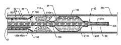
- FIG. 1is a plan view of the thrombectomy catheter system with occluder 10 , the present invention, shown in use with supporting operational sources including, but not limited to, a balloon inflation source 12 , a high pressure source 14 , and a suction source 16 .
- FIG. 2is an exploded isometric view of the thrombectomy catheter system with occluder 10 .
- FIGS. 1 and 2structure of the present invention is now described. Externally visible components, or portions of components, of the thrombectomy catheter system with occluder 10 , as illustrated in FIGS.
- a first structureincluding a manifold 18 , also known as a Y-adapter, a hemostasis nut 20 which secures in the proximal end of the manifold 18 , a Luer connection 22 located at the proximal end of an angled manifold branch 24 extending from the manifold 18 , a Luer fitting 26 secured to the distal end of the manifold 18 , a strain relief 28 , which can be flexible, secured to the distal end of the manifold 18 by the Luer fitting 26 , and a guide catheter 30 suitably attached to the distal end of the manifold 18 via the strain relief 28 .
- a manifold 18also known as a Y-adapter
- a hemostasis nut 20which secures in the proximal end of the manifold 18
- a Luer connection 22located at the proximal end of an angled manifold branch 24 extending from the manifold 18
- a Luer fitting 26secured to the distal
- balloon occluder 34can be an inflatable and deflatable balloon of stiffer polymeric materials such as polyester or PET or composite material, and which may unfold as it is inflated; for example, balloon occluder 34 can also function like an angioplasty balloon.
- Other embodimentsshow occluders which are non-inflatable, yet compliant.
- the balloon occluder 34is located at the distal portion of the occluder guidewire tube 32 .
- a guidewire coil 36which is flexible, is located distal to the balloon occluder 34 and distal to the occluder guidewire tube 32 .
- Another structureincludes a one-piece manifold 38 having multiple components extending therefrom or attached thereto including a capture catheter 40 , a high pressure tube 42 , and other components as described herein.
- the visible portion of the one-piece manifold 38includes a central tubular body 44 , an exhaust branch 46 having branch passage 47 ( FIG. 5 ) and a Luer connection 48 and a flangeless high pressure connection branch 50 extending angularly from the central tubular body 44 , and a cavity body 52 extending proximally from the central tubular body 44 .
- the proximal end of the capture catheter 40secures to the manifold 38 by an interceding streamlined flexible strain relief 54 .
- the proximal end of the capture catheter 40extends through the streamlined flexible strain relief 54 to communicate with the manifold 38 .
- the capture catheter 40extends distally to include a distally located retractable capture cone 56 , the retractable capture cone 56 being shown in the deployed and expanded position.
- a hemostasis nut 58aligned to and snappingly engaged with the proximal region of the cavity body 52 , and a high pressure connection port 60 having threads 62 which is secured such as by, but not limited to, adhesive, to the high pressure connection branch 50 .
- an introducer 64having a hollow shaft 66 , annular rings 68 and 70 about the hollow shaft 66 , and an actuating handle 72 .
- a self-sealing hemostasis valve 76aligns in cavity 78 located proximally in the cavity body 52 to seal about the occluder guidewire tube 32 .
- guide catheter referring to it m 30can be a standard guide catheter as is known in percutaneous interventions, but the meaning is intended to be more general, and to include any generally tubular element through which capture catheter 40 , or variations or alternative embodiments thereof, can pass and which restrains the retractable capture cone 56 , or variations or alternative embodiments thereof, when the retractable capture cone 56 is retracted within the tubular element.
- Guide catheter 30can have other characteristics typical of other tubular elements such as guiding catheters, introducer sheaths, guiding sheaths, angiographic catheters, infusion catheters, and so forth, but must additionally provide for passage of the capture catheter 40 , or variations or alternative embodiments thereof, and provide for restraining the retractable capture cone 56 , or variations or alternative embodiments thereof, in an unexpanded configuration when retractable capture cone 56 is retracted therein.
- Variations or alternative embodiments of capture catheters, retractable capture cones, fluid jet emanators, occluders in the form of balloon occluders or mesh occluders and the like,are described later in detail which can be operated in the structures of the invention to perform similar functions within the teachings of the invention.
- FIG. 3is an exploded cross sectional side view of the manifold 18 and associated components.
- the manifold 18includes a centrally located tapered passage 80 aligned along the longitudinal axis of the manifold 18 and a branch passage 82 which extends along the axis of the manifold branch 24 and which intersects with and is connected to the central tapered passage 80 .
- the proximal end of the manifold 18houses a multi-radius cavity 84 including a round outer cavity portion 86 and a connected round inner and smaller cavity portion 88 having a threaded surface 90 on the proximal portion thereof.
- the hemostasis nut 20includes a body 92 having a grasping surface 94 extending thereabout, a threaded surface 96 extending from the body 92 , an annular surface 98 at the end of the threaded surface 96 , and a passageway 100 aligned centrally to the longitudinal axis of the hemostasis nut 20 .
- the passageway 100has a wide radius at the proximal end which decreases toward the distal end. The initial wide radius is helpful for insertion of the capture catheter 40 , other guidewires, and the like.
- a seal 102aligns to a distally located annular surface 104 of the round inner cavity portion 88 and bears around, about and against the annular surface 98 of the hemostasis nut 20 to seal the tapered passage 80 of the manifold 18 to the passageway 100 in the hemostasis nut 20 , as required.
- the multi-radius cavity 84 and its internal geometryaccommodate corresponding geometry of the hemostasis nut 20 and the seal 102 .
- the strain relief 28is comprised of a tube 106 , a central bore 108 internal to the tube 106 which accommodates the guide catheter 30 , an annular flange 110 about the tube 106 , and a tapered proximal tube mouth end 112 .
- the outer diameter of the tube 106is constant from the annular flange 110 to the distal end of the tube 106 , and that the outer diameter steadily decreases from the annular flange 110 to the tapered proximal tube mouth end 112 to provide a tapered tube surface 114 which conforms, for purpose of a proper fit, to the taper of the tapered central passage surface 118 of the tapered passage 80 .
- the tapered proximal tube mouth end 112allows for easily accomplished alignment of the capture catheter 40 , other guidewires or other assemblies within a lumen 119 located in the guide catheter 30 .
- the Luer fitting 26includes threads 120 which threadingly engage corresponding threads 122 at the distal end of the manifold 18 .
- the Luer fitting 26bears against the annular flange 110 of the strain relief 28 to force the tapered tube surface 114 of the strain relief 28 against the tapered central passage surface 118 of the tapered passage 80 to effect a suitable and stable seal.
- FIG. 4is an assembled cross sectional side view of the manifold 18 and associated components shown in FIG. 3 .
- FIG. 5is an exploded view in partial cross section of the manifold 38 and associated components
- FIG. 6is an assembled view in partial cross section of the components of the manifold 38 and associated components shown in FIG. 5 .
- a portion of the occluder guidewire tube 32is also shown in engagement with the manifold 38 and other associated components.
- the manifold 38 and associated componentsinclude a self-sealing hemostasis valve 76 and also a hemostasis nut 58 which aligns over and about threads 123 at the proximal region of the manifold 38 . Portions of the hemostasis nut 58 and all of the self-sealing hemostasis valve 76 are accommodated internally by the cavity 78 located in the cavity body 52 of the manifold 38 .
- the cavity 78is for the most part tubular in shape including a tubular cavity wall 126 and a planar surface 128 which is annular and circular and which intersects the tubular cavity wall 126 .
- a cavity extension 130being for the most part tubular, extends distally from the cavity 78 beginning at the planar surface 128 to intersect and connect with an orifice 132 .
- the orifice 132is common to the cavity extension 130 , the cavity 78 , and a tapered central passageway 134 located central to the central tubular body 44 .
- the cavity 78accommodates the self-sealing hemostasis valve 76 , which aligns to planar surface 128 .
- the hemostasis nut 58which can provide a slidable seal about the occluder guidewire tube 32 , includes a centrally located cylindrical boss 136 , a beveled passageway 138 extending through and in part forming the cylindrical boss 136 , and internal threads 140 distanced from the cylindrical boss 136 by a distally located space 142 extending along the internal threads 140 and along the distal portion of the cylindrical boss 136 .
- a proximally located space 144is located adjacent to the distally located space 142 .
- An annular stop surface 146is located at the proximal region of the proximally located space 144 .
- the distally located space 142accommodates the proximal end 148 of the manifold 38 including threads 123 located along and about the outer proximal portion of the cavity body 52 of the manifold 38 .
- an annular lip 150which can be utilized for snap engagement of the introducer 64 or other particular styles or types of introducers as required.
- the hemostasis nut 58threadingly engages the manifold 38 where the internal threads 140 of the hemostasis nut 58 engage and are advanced along the threads 123 of the manifold 38 until advancement of the hemostasis nut 58 is predeterminately stopped by impingement of the annular stop surface 146 against the proximal end 148 of the manifold 38 , whereby and whereupon the cylindrical boss 136 is brought to bear directly against the self-sealing hemostasis valve 76 resultingly bringing pressure to bear as required against the self-sealing hemostasis valve 76 to effect sealing with the cavity wall 126 of the cavity 78 , to seal the self-sealing hemostasis valve 76 to the occluder guidewire tube 32 and to seal the self-sealing hemostasis valve 76 to the planar surface 128 .
- a suitable adhesivecan be applied to the internal threads 140 of the hemostasis nut 58 and/or to the threads 123 of the manifold 38 to ensure permanent fixation of the hemostasis nut 58 to the manifold 38 .
- Such adhesive applicationensures fixed and non-adjustable sealing of the self-sealing hemostasis valve 76 to the occluder guidewire tube 32 .
- the self-sealing hemostasis valve 76is captured in the cavity 78 by engagement of the hemostasis nut 58 to the cavity body 52 of the manifold 38 , as shown in FIG. 6 .
- the self-sealing hemostasis valve 76can be inserted into the cavity 78 without regard to the orientation of the opposing sides.
- the streamlined flexible strain relief 54is fitted and adhesively or otherwise suitably affixed to the distal interior portion of the manifold 38 .
- the streamlined flexible strain relief 54can be fashioned of flexible plastic, rubber, or the like and includes a constant radius region 152 adjoined by a short tapered region 154 , each region fitting to and being accommodated respectively by the distal portion of the tapered central passageway 134 and an included short tapered region 156 of the tapered central passageway 134 of the manifold 38 , as shown in FIG. 6 .
- Adjoining the short tapered region 154 of the streamlined flexible strain relief 54is a tapered region 158 located distally thereto.
- a passageway 160extends along the length of the streamlined flexible strain relief 54 for accommodation and passage of the occluder guidewire tube 32 and the high pressure tube 42 .
- An adhesive injection port 162(see also FIG. 1 ) can be located at a suitable location extending through an exterior tapered region 164 of the manifold 38 , which is flangeless, to introduce adhesive 166 to the distal interior region of the manifold 38 including the distal end of the tapered central passageway 134 and the included short tapered region 156 of the tapered central passageway 134 .
- Such adhesive injectioncan be accomplished when the streamlined flexible strain relief 54 is mated to the distal end of the manifold 38 as shown in FIG. 6 , or adhesive may be applied to the mated surfaces separately, or electronic welding or bonding can be incorporated, or adhesive may be otherwise suitably applied as applicable to the art.
- the threaded high pressure connection port 60is fitted and adhesively or otherwise suitably affixed to the interior of a high pressure connection branch passageway 124 of the high pressure connection branch 50 .
- the threaded high pressure connection port 60has a passageway 168 and is fitted to and adhesively or otherwise suitably affixed to the interior of the flangeless high pressure connection branch 50 of the manifold 18 .
- Opposing flats 170are located at the distal portion of the threaded high pressure connection port 60 to adequately receive adhesive 172 in close communication to ensure proper physical fixation and adhering of the threaded high pressure connection port 60 within the high pressure connection branch passageway 124 of the high pressure connection branch 50 .
- An adhesive injection port 174( FIG.
- Adhesive injectioncan be accomplished when the threaded high pressure connection port 60 is mated to the high pressure connection branch 50 of the manifold 38 , as shown in FIG. 6 .
- Adhesivecould also be applied to the mated surfaces separately, or electronic welding or bonding can be incorporated, or adhesive may be otherwise suitably applied as applicable to the art. Also shown is a ferrule 178 which aligns and suitably secures within the passageway 168 of the threaded high pressure connection port 60 , the combination of which aligns partially within the high pressure connection branch passageway 124 of the high pressure connection branch 50 .
- One end of the high pressure tube 42is utilized for delivery of high pressure ablation liquids and suitably secures in a center passage of the ferrule 178 to communicate with the passageway 168 of the threaded high pressure connection port 60 .
- the high pressure tube 42also extends through the high pressure connection branch passageway 124 , through part of the tapered central passageway 134 , through the streamlined flexible strain relief 54 , through the capture catheter 40 , and to the distal end of the capture catheter 40 to align within the retractable capture cone 56 where termination is provided in the form of a fluid jet emanator 180 (see FIGS. 1 , 2 and 9 ).
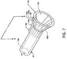
- FIG. 7is an isometric view showing the retractable capture cone 56 in a deployed state at the distal end of the capture catheter 40 .
- the retractable capture cone 56 and a portion of the capture catheter 40can be a composition of materials including a plurality of expansion struts 182 a – 182 n where, for illustration purposes, expansion strut 182 a is shown distant from the structure of the deployed retractable capture cone 56 .
- the expansion struts 182 a – 182 nare preferably metallic or are of other such suitable material which can be formed to provide spring-like qualities having position memory in order to expandingly form the cone-like shape of the retractable capture cone 56 .
- the expansion struts 182 a – 182 nare encapsulated in polymers forming the capture catheter 40 and retractable capture cone 56 such as, but not limited to, PTFE, PEBAX, polyethylene, PET, polyamide, polyurethane or silicone.
- the expansion struts 182 a – 182 nare preferably of metallic material such as, but not limited to, stainless steel, nitinol, nickel, platinum, iridium or tungsten.
- the expansion struts 182 a – 18 nare preformed having a bend or curve 184 located between a straight strut portion 186 which resides generally in the non-cone-shaped distal region of the capture catheter 40 and a straight strut portion 188 directed at an angle from the first straight strut portion 186 and residing in the retractable capture cone 56 .
- the interior conical surface 190 of the retractable capture cone 56connects to and is in common with a lumen 192 extending the length of the capture catheter 40 .
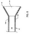
- FIG. 8is a cross section view of the retractable capture cone 56 along line 8 — 8 of FIG. 7 showing more clearly the expansion struts 182 a – 182 n located within the retractable capture cone 56 .
- FIG. 9is an isometric view of the fluid jet emanator 180 located distally at one end the high pressure tube 42 .
- the fluid jet emanator 180is a loop formed of the high pressure tube 42 .
- a lumen 194delivers high pressure saline or other such suitable fluid to the fluid jet emanator 180 .
- a plurality of rearwardly and proximally directed jet orifices 196 a – 196 nare located along the proximally facing portion of the fluid jet emanator 180 .
- High pressure saline delivered by the lumen 194is forced into the fluid jet emanator 180 to cause saline fluid jets 198 a – 198 n to emanate from the rearwardly and proximally directed jet orifices 196 a – 196 n .
- Such fluid jets 198 a – 198 nare directed into the retractable capture cone 56 and are utilized to macerate, entrain and carry away thrombus, as later described in detail.
- the loop center 200 of the fluid jet emanator 180accommodates passage of the occluder guidewire tube 32 .
- a capture catheter support band 201such as shown in this and alternate embodiments suitably attaches such as by a weld 203 to the high pressure tube 42 to maintain the position and orientation of the fluid jet emanator 180 with respect to the center of the support band 201 and also to the centerline of the capture catheter 42 , as shown in FIG. 10 .
- the fluid jet emanator 180is shown as a loop formed of the high pressure tube 42 , other suitably fashioned or shaped emanator designs can be utilized as an emanator and the use of the fluid jet emanator 180 having a loop shall not be considered to be limiting to the scope of the invention.
- J-shaped, L-shaped, U-shaped, arcuate-shaped, semi-torodial-shaped, or other-shaped emanator(s)can be utilized.
- the emanatorcan have a single jet orifice from which a single fluid jet emanates, or a plurality of jet orifices from which a plurality of fluid jets emanate.
- the preferred configurationincludes a plurality of proximally directed jet orifices.
- FIG. 10is a transparent isometric view in partial cross section illustrating the alignment and attachment of the high pressure tube 42 within the lumen 192 of the capture catheter 40 , which also favorably influences and provides for the alignment and fixed positioning of the fluid jet emanator 180 with the retractable capture cone 56 .
- Such fixed positioning and alignmentis provided by the capture catheter support band 201 being fixedly aligned within the lumen 192 of the capture catheter 40 .
- the capture catheter support band 201is positionally fixed within the lumen 192 by frictional engagement of a cylindrically shaped radiopaque marker band 205 , such as shown in this and alternate embodiments, engaged over and about the capture catheter 40 .
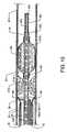
- FIG. 11is a longitudinal cross section view of the distal region of the capture catheter 40 including the collapsed retractable capture cone 56 , and the fluid jet emanator 180 aligned in the distal region of the capture catheter 40 prior to deployment of the retractable capture cone 56 . Also shown is the occluder guidewire tube 32 aligned within the lumen 192 of the capture catheter 40 . Also shown is the guide catheter 30 in which the capture catheter 40 aligns.
- FIG. 12is a longitudinal cross sectional view of the distal region of the occluder guidewire tube 32 .
- a weld 202which joins together the extreme distal portion of the occluder guidewire tube 32 , the proximal end of the guidewire coil 36 , and the proximal end of a tapered flexible core 204 .
- a weld 206is also included at the distal end of the guidewire coil 36 to secure the distal end of the tapered flexible core 204 to the distal end of the guidewire coil 36 and to provide for smooth entry into a vessel or body cavity device orifice.
- the balloon occluder 34aligns around and about the distal portion of the occluder guidewire tube 32 and the distal and proximal ends of the balloon occluder 34 secure by adhesive 208 or other suitable attachment means to the periphery of the occluder guidewire tube 32 .
- Such securingseals the balloon occluder 34 to the periphery of the occluder guidewire tube 32 to allow sustained inflation of the balloon occluder 34 by pressurizing the lumen 193 with a medium such as liquid or gas whereby such pressurizing medium is delivered through a plurality of inflation orifices 210 a – 210 n located around and about the distal portion of the occluder guidewire tube 32 .
- a single inflation orificecan be used, although this is not the preferred configuration.
- FIGS. 1 and 13 – 17illustrate the mode of operation of the thrombectomy catheter system with occluder 10 and the method of using the same.
- FIG. 1shows the thrombectomy catheter system with occluder 10 in use with supporting operational sources including, but not limited to, a balloon inflation source 12 , a high pressure source 14 , and a suction source 16 . Fluoroscopy is incorporated to monitor the position of the invasive components of the system in the region of thrombus residing in the vasculature.
- the distal end of the guide catheter 30is advanced into a blood vessel 214 or other vessel to a position just proximal of a buildup of thrombus 212 or other undesirable embolic materials.
- Such advancementinvolves the manipulation of the manifold 18 to which the guide catheter 30 is attached.
- the distal end of the occluder guidewire tube 32is then loaded through the hemostasis nut 20 and into and through the manifold 18 and thence through the lumen 119 of the guide catheter 30 and advanced beyond the distal end of the guide catheter 30 .
- the distal end of the occluder guidewire tube 32including the guidewire coil 36 and the balloon occluder 34 , is advanced through and beyond the thrombus 212 , as shown in FIG. 14 , whereby the proximal end of the balloon occluder 34 is positioned just distal of the thrombus 212 .
- the proximal end of the occluder guidewire tube 32 of suitable lengthis left extending a suitable distance beyond the proximal end of the hemostasis nut 20 for accommodation of the capture catheter 40 and various associated components of the manifold 38 attached thereto.
- the distal end of the capture catheter 40including the retractable capture cone 56 and the fluid jet emanator 180 , is then loaded over the proximal end of the occluder guidewire tube 32 where the lumen 192 of the capture catheter 40 and the loop center 200 of the fluid jet emanator 180 accommodate the occluder guidewire tube 32 .
- Saline or other suitable medium as provided by the balloon inflation source 12pressurizes the lumen 193 of the occluder guidewire tube 32 to deliver pressurized saline 195 through the plurality of inflation orifices 210 a – 210 n to inflate and expand the balloon occluder 34 to occlude the blood vessel 214 , as shown in FIG. 15 .
- the manifold 38is then maneuvered to ensure full and proper positioning of the capture catheter 40 and especially the retractable capture cone 56 with respect to the distal end of the guide catheter 30 and the thrombus 212 , as shown in FIG. 15 .
- the retractable capture cone 56when positioned suitably beyond the distal end of the guide catheter 30 , expands with the aid of the expansion struts 182 a – 182 n to a cone shape to contact the inner periphery of the blood vessel 214 .
- the balloon occluder 34is inflated and when the retractable capture cone 56 is fully deployed, each against the wall of the blood vessel 214 , maceration and removal of thrombus 212 is then commenced, as shown in and as described with reference to FIGS. 16 and 17 .
- high pressure mediumsuch as high pressure saline such as provided by the high pressure source 14 is delivered by the lumen 194 of the high pressure tube 42 and forced into the fluid jet emanator 180 to cause rearwardly directed saline fluid jets 198 a – 198 n (also seen in FIG. 9 ) to emanate from the rearwardly directed jet orifices 196 a – 196 n .
- Such fluid jets 198 a – 198 nare directed into the retractable capture cone 56 and are utilized to macerate, entrain and carry away thrombus 212 , the delivery of which is caused by the proximal urging of the inflated balloon occluder 34 .
- Proximally directed urging of the thrombus 212 by the inflated balloon occluder 34is facilitated by manipulation of the manifold 38 which, being connected to and in direct communication with the occluder guidewire tube 32 and attached inflated balloon occluder 34 , impinges, dislodges, reshapes and redistributes the thrombus 212 in a proximal direction for subsequent interaction with the rearwardly directed saline fluid jets 198 a – 198 n .
- Proximally urged thrombus 212is forced by the proximally directed balloon occluder 34 into the deployed retractable capture cone 56 proximally towards, about and around the fluid jet emanator 180 where the proximally directed fluid jets 198 a – 198 n impinge, dislodge, macerate, reduce and otherwise influence the shape and structure of the thrombus 212 for evacuation.
- Suction appropriately applied to the lumen 192 of the capture catheter 40such as by the suction source 16 , creates a low pressure which, along with the rearwardly directed fluid jets 198 a – 198 n , carries the macerated thrombus 212 proximally for collection at the suction source 16 .
- FIG. 17shows the inflated balloon occluder 34 near impingement with the retractable capture cone 56 where the majority of the thrombus 212 has been macerated at the retractable capture cone 56 and evacuated through the lumen 192 of the capture catheter 40 .
- the balloon occluder 34can be deflated and collapsed to the same size or smaller size than the capture catheter 40 such as by relieving or even applying negative pressure at the balloon inflation source 12 .
- Such reduction in size of the balloon occluder 34allows manipulation of the occluder guidewire tube 32 proximally to retract the collapsed balloon occluder 34 into the capture catheter 40 .
- the capture catheter 40can be retracted proximally to retractably collapse the retractable capture cone 56 to conform to the inner regions of the guide catheter 30 whereupon the capture catheter 40 and the occluder guidewire tube 32 can be withdrawn simultaneously, if desired.
- the guide catheter 30 , the capture catheter 40 and the occluder guidewire tube 32could be advanced distally as required to facilitate the removal of other thrombus as required.
- FIG. 18is an alternative embodiment where the retractable capture cone 56 and expansion struts 182 a – 182 n previously described are replaced by a retractable capture cone 216 preferably of flexible plastic mesh 217 formed by weaving, braiding, or other such interlacing of strands, filaments or the like, preferably of Nitinol, or other materials such as nylon or polyurethane, or metallic or other non-metallic flexible materials all having position memory.
- the retractable capture cone 216functions much the same as the retractable capture cone 56 whereby the retractable capture cone 216 can conformingly assume a cylindrical shape when residing adjacent to, in alignment with, and in communication with a lumen 192 a of a capture catheter 40 a where such capture catheter 40 a replaces and is like capture catheter 40 but includes a distal annular recess 220 for accommodation and suitable attachment, such as by, but not limited to, adhesive 219 ( FIG. 19 ), depending on the material used, of the proximal end of the retractable capture cone 216 .
- the retractable capture cone 216because of positional memory can expand outwardly to form a conical or other suitable useful shape which can contact the inner periphery of the blood vessel 214 .
- the retractable capture cone 216is of close-knit material, such as described above, which does not allow fluids to pass therethrough and which functions in a somewhat identical manner to the retractable capture cone 56 where a conical surface 218 on the inside of the retractable capture cone 216 functions to channel thrombus 212 and receive fluid jets 198 a – 198 n for thrombus maceration and subsequent thrombus evacuation through the lumen 192 a of the capture catheter 40 a according to the teachings of the invention.
- FIG. 19is a cross section view of the capture catheter 40 a and retractable capture cone 216 along line 19 — 19 of FIG. 18 .
- Shown in particularis the annular recess 220 which accommodates the proximal end of the retractable catheter cone 216 and which accommodates a suitable attachment medium such as an adhesive 219 , or, alternatively, weldments or other attachment means.
- the annular recess 220provides for attachment of the retractable capture cone 216 having no protrusions or irregular surfaces which can interfere with smooth unencumbered passage of the union of the capture catheter 40 a and the retractable capture cone 216 at the distal tip of the guide catheter 30 .
- FIGS. 20 , 21 and 22illustrate an alternative embodiment fluid jet emanator 222 which can be utilized in lieu of the previously described fluid jet emanator 180 .
- FIG. 20is an exploded isometric view depicting the alternative fluid jet emanator 222 and the relationship of the capture catheter support band 201 to a high pressure tube 42 a .
- FIG. 21is an assembled isometric view of the elements of FIG. 20 ; and
- FIG. 22is a transparent isometric view of the elements of FIGS. 20 and 21 in partial cross section illustrating the alignment and attachment of the high pressure tube 42 a within the lumen 192 of the capture catheter 40 which also favorably influences and provides for the alignment and fixed positioning of the fluid jet emanator 222 with the retractable capture cone 56 .
- the capture catheter support band 201is fixedly aligned within the lumen 192 of the capture catheter 40 .
- the capture catheter support band 201secures such as by a weld 224 or other suitable attachment means to the lower surface of the high pressure tube 42 a .
- the capture catheter support band 201is fixed at a suitable position along the interior (lumen 192 ) of the capture catheter 40 by the compressional frictional engagement of a radiopaque marker band 205 over and about the capture catheter 40 , as shown in FIG. 22 .
- the high pressure tube 42 ais reduced in diameter at the high pressure tube 42 a distal end 226 for suitable engagement with the fluid jet emanator 222 .
- the fluid jet emanator 222is built as a structure outwardly resembling the general shape of a disk.
- the fluid jet emanator 222includes a cylindrical main body 228 , an annular manifold groove 230 in the form of a circular groove at the proximal end of the cylindrical main body 228 , a centrally located tubular extension 232 extending proximally from the proximal end of the main body 228 and being coaxial with the annular manifold groove 230 , a manifold plate 234 aligned to the annular manifold groove 230 and the adjacent planar annular surfaces having a plurality of jet orifices 236 a – 236 n , a centrally located hole 238 , and an offset hole 240 .
- the centrally located hole 238is aligned to and accommodated by the tubular extension 232 .
- the manifold plate 234is also aligned substantially to the proximal end of the main body 228 during the mating of the centrally located hole 238 and the tubular extension 232 .
- a passageway 242aligns to the longitudinal axis of the main body 228 , the center of the tubular extension 232 and to the center of the centrally located hole 238 of the manifold plate 234 .
- An annular manifoldis formed when the manifold plate 234 is mated over and about the annular manifold groove 230 of the main body 228 , at which time the plurality of jet orifices 236 a – 236 n and the offset hole 240 are brought into close communicational sealed alignment with the annular manifold groove 230 in the main body 228 .
- High pressure fluidsuch as saline or other suitable solution is delivered through the lumen 194 a of the high pressure tube 42 a to the fluid jet emanator 222 and distributed through the formed manifold to the plurality of jet orifices 236 a – 236 n , whereby high velocity jet flow emanates proximally for maceration of thrombus delivered to the retractable capture cone 56 by the balloon occluder 34 or other suitably fashioned structure described herein for subsequent evacuation through the capture catheter 40 .
- the radiopaque marker band 205positions near and over and about the distal end of the capture catheter 40 for engagement of the capture catheter 40 by compressional frictional engagement and causes the capture catheter 40 to frictionally engage the capture catheter support band 201 , as shown in FIG. 22 .
- the capture catheter 40 a and the mesh style retractable capture cone 216 previously describedcould be incorporated in lieu of the capture catheter 40 and the retractable capture cone 56 shown in FIG. 22 .
- FIG. 23is a cross section view of an alternative embodiment incorporating a controllable-shape mesh occluder 244 having structure providing a shape when expanded and distended substantially similar to and performing the same thrombotic influencing function as the previously described inflated balloon occluder 34 .
- the controllable-shape mesh occluder 244is not inflatable but has a shape which is controllable and which is distendingly expandable.
- the controllable-shape mesh occluder 244is fabricated of flexible mesh 246 , which can be a braid, a weave, or other interlacing strands or the like of metallic or non-metallic flexible materials, which optionally can include positional memory.
- the flexible mesh 246is of close-knit material, such as described above, which does not allow fluids to pass therethrough.
- the controllable-shape mesh occluder 244 and the occluder guidewire tube 32 acan be utilized in lieu of the balloon occluder 34 and the occluder guidewire tube 32 previously described according to the teachings of the invention where the controllable-shape mesh occluder 244 is positioned and expandingly deployed to assume a shape generally resembling the balloon occluder 34 .
- the occluder guidewire tube 32 ahaving a lumen 193 a , replaces and is like the occluder guidewire tube 32 , but includes a distal annular recess 248 for accommodation and suitable attachment thereto, such as by, but not limited to, adhesive 247 , depending on the material used, of the proximal end of the flexible mesh 246 which forms the controllable-shape mesh occluder 244 .
- a control rod 250extends in the lumen 193 a the length of the occluder guidewire tube 32 a to exit the occluder guidewire tube 32 a at the proximal end of the occluder guidewire tube 32 a and to extend beyond so that the physician operator may adjustably control the control rod 250 .
- the distal portion of the control rod 250 which extends beyond the distal end of the controllable-shape mesh occluder 244has the shape and characteristics of the tip of any ordinary coronary guidewire of the previously shown tapered flexible core 204 to form a tapered flexible core 250 a .
- a weld 202 aattaches the proximal end of a guidewire coil 36 a to the proximal end of the tapered flexible core 250 a
- a weld 206 aattaches the distal end of the guidewire coil 36 a to the distal end of the tapered flexible core 250 a .
- control rod 250 and the tapered flexible core 250 acould be separate elements mutually joined with the guidewire coil 36 a at weld 202 a .
- the distal end of the controllable-shape mesh occluder 244suitably attaches, such as by use of adhesive 247 or other suitable means to the distal end of the control rod 250 adjacent to the weld 202 a.
- FIG. 24is a view in cross section illustrating the use of the elements of FIG. 23 where the controllable-shape mesh occluder 244 and the occluder guidewire tube 32 a and associated components are loaded through the guide catheter 30 (not shown) and utilized in lieu of the balloon occluder 34 and the occluder guidewire tube 32 .
- the balloon inflation source 12 of FIG. 1is not utilized. Several loading and positioning techniques can be utilized.
- control rod 250is simply advanced a suitable distance distally, thereby pulling the attached controllable-shape mesh occluder 244 , which maintains a low profile because of tension along the controllable-shape mesh occluder 244 , and the attached occluder guidewire tube 32 a through the guide catheter 30 .
- loadingis accomplished in the following manner.
- the physician operatorcontrols the relationship of and positions the control rod 250 in a distal direction with respect to the occluder guidewire tube 32 a to cause the controllable-shape mesh occluder 244 to assume and maintain a collapsed low profile, as shown in FIG. 23 , followed by unitary advancement of the guidewire coil 36 a , the low profile controllable-shape mesh occluder 244 , and the distal end of the occluder guidewire tube 32 a distally beyond the thrombus 212 to a position such as shown in FIG. 14 .
- the occluder guidewire tube 32 ais held steady and the control rod is retracted proximally a sufficient distance to cause expansion and distention of the controllable-shape mesh occluder 244 to be compliant with and to occlude the blood vessel 214 or other blood carrying structure where the occluding relationship of the occluder guidewire tube 32 a and the controllable-shape mesh occluder 244 is maintained and is then unitarily retracted proximally to urge thrombus 212 in a proximal direction juxtaposing the subsequently loaded retractable capture cone 56 and capture catheter 40 and other components for maceration according to the teachings of the invention.
- control rod 250can be repositioned distally with respect to the occluder guidewire tube 32 a to collapse the controllable-shape mesh occluder 244 and to withdraw the guidewire coil 36 a , the low profile controllable-shape mesh occluder 244 , and the distal end of the occluder guidewire tube 32 a unitarily.
- FIG. 25is an isometric view of an alternative embodiment incorporating an occluder having structure substantially similar to and performing the same thrombotic influencing function as the previously described inflated balloon occluder 34 .
- a flexible shaped mesh occluder 252which is not inflatable but has a predetermined shape which is flexible, compressible, and utilizes positional memory to maintain a balloon-like shape suitable for occluding a blood vessel and for urging thrombotic material proximally for maceration.
- the flexible shaped mesh occluder 252is fabricated of mesh 254 , which can be a braid, a weave, or other interlacing strands or the like of metallic or non-metallic flexible materials which include position memory.
- the mesh 254is of close-knit material, such as described above, which does not allow fluids to pass therethrough.
- the flexible shaped mesh occluder 252can be utilized in lieu of the balloon occluder 34 previously described according to the teachings of the invention where the flexible shaped mesh occluder 252 is positioned and expandingly deployed to assume a shape generally resembling the balloon occluder 34 .
- FIG. 26is a cross section view of the embodiment of FIG. 25 showing the flexible shaped mesh occluder 252 in a compressed state forced to a low profile from positional memory such as for transferring through a lumen.
- the flexible shaped mesh occluder 252aligns over and about a control rod 256 .
- the control rod 256extends in the lumen 119 the length of the guide catheter 40 to exit the manifold 38 at the hemostasis nut 58 so that the physician operator may adjustably control the control rod 256 .
- the distal portion of the control rod 256 which extends beyond the distal end of the flexible shaped mesh occluder 252has the shape and characteristics of the tip of any coronary guidewire of the previously shown tapered flexible core 204 to form a tapered flexible core 256 a .
- a weld 202 battaches the proximal end of a guidewire coil 36 b to the proximal end of the tapered flexible core 256 a
- a weld 206 battaches the distal end of the guidewire coil 36 b to the distal end of the tapered flexible core 256 a
- the control rod 256 and the tapered flexible core 256 acould be separate elements mutually joined with the guidewire coil 36 b at weld 202 b .
- the distal end of the flexible shaped mesh occluder 252suitably attaches, such as by use of adhesive 247 or other suitable means, to the distal end of the control rod 256 adjacent the weld 202 b .
- the proximal end of the flexible shaped mesh occluder 252slidingly aligns to the control rod 256 and is free to position thereupon, thereby allowing the geometry of the flexible shaped mesh occluder 252 to be varied.
- FIG. 27is a view illustrating the use of the elements of FIG. 26 where the flexible shaped mesh occluder 252 , the control rod 256 , and associated components are utilized in lieu of the balloon occluder 34 and the occluder guidewire tube 32 .
- the balloon inflation source 12 of FIG. 1is not utilized.
- the flexible shaped mesh occluder 252 , the control rod 256 , and associated componentsare introduced into the blood vessel 214 through the guide catheter 30 (not shown) where the distal end of the guide catheter 30 is first positioned through and distal to the thrombus 212 .
- the flexible shaped mesh occluder 252is compressed to assume a low profile, as shown in FIG. 26 , for insertion into the manifold 38 , the capture catheter 40 , the manifold 18 and the guide catheter 30 .
- the physician operatorcontrols the relationship of and positions the control rod 256 in a distal direction with respect to the guide catheter 30 where the flexible shaped mesh occluder 252 continues to assume and maintain a collapsed low profile as shown in FIG.
- a short distal portion of the guide catheter 30 distal to the thrombus 212contains the guidewire coil 36 b , the low profile flexible shaped mesh occluder 252 and the distal end of the control rod 256 .
- control rod 256is held steady and the guide catheter 30 is positioned proximally a sufficient distance to disengage from surrounding and encompassing contact with the flexible shaped mesh occluder 252 allowing expansion and distention of the flexible shaped mesh occluder 252 to be compliant with and to occlude the blood vessel 214 or other blood carrying structure where the occluding relationship of the control rod 256 and the flexible shaped mesh occluder 252 is maintained with the blood vessel 214 and is then unitarily retracted proximally to urge thrombus 212 in a proximal direction juxtaposing the subsequently loaded retractable capture cone 56 and capture catheter 40 and other components for maceration according to the teachings of the invention.
- the guide catheter 30can be advanced distally and the control rod 256 can be repositioned proximally with respect to guide catheter 30 to engage and collapse and compress the flexible shaped mesh occluder 252 and withdraw the guidewire coil 36 b , the low profile compressed flexible shaped mesh occluder 252 , and the distal end of the control rod 256 unitarily.
Landscapes
- Health & Medical Sciences (AREA)
- Surgery (AREA)
- Life Sciences & Earth Sciences (AREA)
- Heart & Thoracic Surgery (AREA)
- Nuclear Medicine, Radiotherapy & Molecular Imaging (AREA)
- Vascular Medicine (AREA)
- Engineering & Computer Science (AREA)
- Biomedical Technology (AREA)
- Medical Informatics (AREA)
- Molecular Biology (AREA)
- Animal Behavior & Ethology (AREA)
- General Health & Medical Sciences (AREA)
- Public Health (AREA)
- Veterinary Medicine (AREA)
- Orthopedic Medicine & Surgery (AREA)
- Surgical Instruments (AREA)
Abstract
Description
Claims (24)
Priority Applications (4)
| Application Number | Priority Date | Filing Date | Title |
|---|---|---|---|
| US10/702,815US7220269B1 (en) | 2003-11-06 | 2003-11-06 | Thrombectomy catheter system with occluder and method of using same |
| DK04818614.2TDK1696966T3 (en) | 2003-11-06 | 2004-11-02 | Thrombectomy catheter system with occlus |
| EP04818614.2AEP1696966B8 (en) | 2003-11-06 | 2004-11-02 | Thrombectomy catheter system with occluder |
| PCT/US2004/036451WO2005046736A2 (en) | 2003-11-06 | 2004-11-02 | Thrombectomy catheter system with occluder and method of using same |
Applications Claiming Priority (1)
| Application Number | Priority Date | Filing Date | Title |
|---|---|---|---|
| US10/702,815US7220269B1 (en) | 2003-11-06 | 2003-11-06 | Thrombectomy catheter system with occluder and method of using same |
Publications (1)
| Publication Number | Publication Date |
|---|---|
| US7220269B1true US7220269B1 (en) | 2007-05-22 |
Family
ID=34590711
Family Applications (1)
| Application Number | Title | Priority Date | Filing Date |
|---|---|---|---|
| US10/702,815Expired - LifetimeUS7220269B1 (en) | 2003-11-06 | 2003-11-06 | Thrombectomy catheter system with occluder and method of using same |
Country Status (4)
| Country | Link |
|---|---|
| US (1) | US7220269B1 (en) |
| EP (1) | EP1696966B8 (en) |
| DK (1) | DK1696966T3 (en) |
| WO (1) | WO2005046736A2 (en) |
Cited By (110)
| Publication number | Priority date | Publication date | Assignee | Title |
|---|---|---|---|---|
| US20040260333A1 (en)* | 1997-11-12 | 2004-12-23 | Dubrul William R. | Medical device and method |
| US20070088379A1 (en)* | 2005-10-17 | 2007-04-19 | Jacob Schneiderman | Minimally invasive a AAPT extirpation |
| US20080275393A1 (en)* | 2004-08-24 | 2008-11-06 | Bonnette Michael J | Isolation thrombectomy catheter system |
| WO2009079539A1 (en)* | 2007-12-17 | 2009-06-25 | Medrad, Inc. | Rheolytic thrombectomy catheter with self-inflation distal balloon |
| US20090192485A1 (en)* | 2008-01-28 | 2009-07-30 | Heuser Richard R | Snare device |
| US20090222035A1 (en)* | 2006-03-27 | 2009-09-03 | Tel Hashomer Medical Research Infrastructure And S | Intraluminal Mass Collector |
| US20090264859A1 (en)* | 2008-04-21 | 2009-10-22 | Medtronic Vascular, Inc. | Catheter Having a Selectively Expandable Distal Tip |
| US20100010499A1 (en)* | 2008-07-10 | 2010-01-14 | Cook Incorporated | Hydraulic guidewire advancement system |
| WO2010034021A2 (en) | 2008-09-22 | 2010-03-25 | Hotspur Technologies, Inc. | Flow restoration systems and methods for use |
| US20100185210A1 (en)* | 2004-03-25 | 2010-07-22 | Hauser David L | Method of Capturing and Macerating Particles in a Blood Vessel |
| US7846175B2 (en) | 2006-04-03 | 2010-12-07 | Medrad, Inc. | Guidewire and collapsable filter system |
| US20110152908A1 (en)* | 2009-12-16 | 2011-06-23 | Medrad, Inc. | Catheter Including Composite Guide and Methods for use and manufacturing of the Same |
| US20110251509A1 (en)* | 2008-09-09 | 2011-10-13 | Pulmonx Corporation | Systems and methods for inhibiting secretion flow into a functional assessment catheter |
| US20110257622A1 (en)* | 2010-03-24 | 2011-10-20 | Amr Salahieh | Intravascular Tissue Disruption |
| US8057497B1 (en) | 2009-07-28 | 2011-11-15 | Seshadri Raju | Thrombectomy removal device kit |
| US8162878B2 (en) | 2005-12-05 | 2012-04-24 | Medrad, Inc. | Exhaust-pressure-operated balloon catheter system |
| EP2230986A4 (en)* | 2007-12-28 | 2012-05-09 | Boston Endoscopic Engineering Corp | Exchangeable guide-wire with balloon for foreign body extraction |
| US8439878B2 (en) | 2007-12-26 | 2013-05-14 | Medrad, Inc. | Rheolytic thrombectomy catheter with self-inflating proximal balloon with drug infusion capabilities |
| US8647294B2 (en) | 2008-03-20 | 2014-02-11 | Medrad, Inc. | Direct stream hydrodynamic catheter system |
| US8663259B2 (en) | 2010-05-13 | 2014-03-04 | Rex Medical L.P. | Rotational thrombectomy wire |
| US8764779B2 (en) | 2010-05-13 | 2014-07-01 | Rex Medical, L.P. | Rotational thrombectomy wire |
| US8795322B2 (en) | 2002-04-01 | 2014-08-05 | W. L. Gore & Associates, Inc. | Methods of manufacture and use of endoluminal devices |
| US20140324091A1 (en)* | 2012-11-20 | 2014-10-30 | Inceptus Medical, Llc | Methods and apparatus for treating embolism |
| US9023077B2 (en) | 2002-10-17 | 2015-05-05 | W.L. Gore & Associates, Inc. | Embolic filter frame having looped support strut elements |
| US9023070B2 (en) | 2010-05-13 | 2015-05-05 | Rex Medical, L.P. | Rotational thrombectomy wire coupler |
| US20150257782A1 (en)* | 2014-03-14 | 2015-09-17 | Michael Chaim Cohn | Adjustable Catheter System |
| US9186487B2 (en) | 1997-11-12 | 2015-11-17 | Genesis Technologies Llc | Medical device and method |
| US9204887B2 (en) | 2012-08-14 | 2015-12-08 | W. L. Gore & Associates, Inc. | Devices and systems for thrombus treatment |
| US20150351775A1 (en)* | 2014-06-04 | 2015-12-10 | Nfinium Vascular Technologies, Llc | Low radial force vascular device and method of occlusion |
| US20150359547A1 (en)* | 2014-06-13 | 2015-12-17 | Neuravi Limited | Devices and methods for removal of acute blockages from blood vessels |
| US9238122B2 (en) | 2012-01-26 | 2016-01-19 | Covidien Lp | Thrombectomy catheter systems |
| US9259237B2 (en) | 2013-07-12 | 2016-02-16 | Inceptus Medical, Llc | Methods and apparatus for treating pulmonary embolism |
| EP3017775A1 (en) | 2014-11-07 | 2016-05-11 | National University of Ireland, Galway | A thrombectomy device |
| WO2016118594A1 (en)* | 2015-01-21 | 2016-07-28 | Government Of The United States, As Represented By The Secretary Of The Air Force | Endovascular variable aortic control catheter |
| US9498604B2 (en) | 1997-11-12 | 2016-11-22 | Genesis Technologies Llc | Medical device and method |
| US9526864B2 (en) | 2014-06-09 | 2016-12-27 | Inceptus Medical, Llc | Retraction and aspiration device for treating embolism and associated systems and methods |
| US9554904B2 (en) | 2011-09-28 | 2017-01-31 | Medtronic CV Luxembourg S.a.r.l. | Distal tip assembly for a heart valve delivery catheter |
| US9561094B2 (en) | 2010-07-23 | 2017-02-07 | Nfinium Vascular Technologies, Llc | Devices and methods for treating venous diseases |
| US9586023B2 (en) | 1998-02-06 | 2017-03-07 | Boston Scientific Limited | Direct stream hydrodynamic catheter system |
| US9592068B2 (en) | 2013-03-15 | 2017-03-14 | Insera Therapeutics, Inc. | Free end vascular treatment systems |
| US20170105743A1 (en)* | 2014-06-13 | 2017-04-20 | Neuravi Limited | Devices and methods for removal of acute blockages from blood vessels |
| US9750524B2 (en) | 2013-03-15 | 2017-09-05 | Insera Therapeutics, Inc. | Shape-set textile structure based mechanical thrombectomy systems |
| US9795406B2 (en) | 2010-05-13 | 2017-10-24 | Rex Medical, L.P. | Rotational thrombectomy wire |
| US20170325931A1 (en)* | 2007-10-26 | 2017-11-16 | Embolitech, Llc | Intravascular guidewire filter system for pulmonary embolism protection and embolism removal or maceration |
| US9833251B2 (en) | 2013-03-15 | 2017-12-05 | Insera Therapeutics, Inc. | Variably bulbous vascular treatment devices |
| US9844387B2 (en) | 2015-10-23 | 2017-12-19 | Inari Medical, Inc. | Intravascular treatment of vascular occlusion and associated devices, systems, and methods |
| US9901435B2 (en) | 2013-03-15 | 2018-02-27 | Insera Therapeutics, Inc. | Longitudinally variable vascular treatment devices |
| US9931495B2 (en) | 2010-02-23 | 2018-04-03 | Covidien Lp | Devices and methods for vascular recanalization |
| JP2018086267A (en)* | 2016-11-28 | 2018-06-07 | ニューラヴィ・リミテッド | Devices and methods for removal of acute blockages from blood vessels |
| US10045790B2 (en) | 2012-09-24 | 2018-08-14 | Inari Medical, Inc. | Device and method for treating vascular occlusion |
| US10098651B2 (en) | 2017-01-10 | 2018-10-16 | Inari Medical, Inc. | Devices and methods for treating vascular occlusion |
| CN108852465A (en)* | 2018-09-17 | 2018-11-23 | 夏印 | Multifunctional ceiling pin device |
| US10238406B2 (en) | 2013-10-21 | 2019-03-26 | Inari Medical, Inc. | Methods and apparatus for treating embolism |
| US20190125561A1 (en)* | 2017-10-30 | 2019-05-02 | Robert M. Sullivan | System and method for deploying a stent in a vessel of a subject |
| US10342571B2 (en) | 2015-10-23 | 2019-07-09 | Inari Medical, Inc. | Intravascular treatment of vascular occlusion and associated devices, systems, and methods |
| US10390926B2 (en) | 2013-07-29 | 2019-08-27 | Insera Therapeutics, Inc. | Aspiration devices and methods |
| CN110313984A (en)* | 2018-03-30 | 2019-10-11 | 上海微创电生理医疗科技股份有限公司 | A kind of ablation catheter and ablation system |
| US10531882B2 (en)* | 2016-01-04 | 2020-01-14 | Alcyone Lifesciences, Inc. | Methods and devices for treating stroke |
| US10779852B2 (en) | 2013-03-15 | 2020-09-22 | National University Of Ireland, Galway | Device suitable for removing matter from inside the lumen and the wall of a body lumen |
| US11000682B2 (en) | 2017-09-06 | 2021-05-11 | Inari Medical, Inc. | Hemostasis valves and methods of use |
| US11065017B2 (en) | 2018-01-25 | 2021-07-20 | Ischemicure Ltd. | Devices, systems and methods to remove blood clots |
| US11076876B2 (en) | 2014-06-30 | 2021-08-03 | Neuravi Limited | System for removing a clot from a blood vessel |
| US11103263B2 (en) | 2015-07-24 | 2021-08-31 | Ichor Vascular Inc. | Embolectomy system and methods of making and using same |
| US11154314B2 (en) | 2018-01-26 | 2021-10-26 | Inari Medical, Inc. | Single insertion delivery system for treating embolism and associated systems and methods |
| US11304713B2 (en)* | 2018-09-07 | 2022-04-19 | Merit Medical Systems, Inc. | Thrombosis macerating and aspiration devices for blood vessels |
| US11311304B2 (en) | 2019-03-04 | 2022-04-26 | Neuravi Limited | Actuated clot retrieval catheter |
| US11395667B2 (en) | 2016-08-17 | 2022-07-26 | Neuravi Limited | Clot retrieval system for removing occlusive clot from a blood vessel |
| US11433218B2 (en) | 2015-12-18 | 2022-09-06 | Inari Medical, Inc. | Catheter shaft and associated devices, systems, and methods |
| US11484328B2 (en) | 2014-03-11 | 2022-11-01 | Neuravi Limited | Clot retrieval system for removing occlusive clot from a blood vessel |
| CN115317077A (en)* | 2022-10-13 | 2022-11-11 | 成都百瑞恒通医疗科技有限公司 | Thrombus taking device |
| US20220387062A1 (en)* | 2007-02-05 | 2022-12-08 | Walk Vascular, Llc | Thrombectomy apparatus and method |
| WO2022261448A1 (en)* | 2021-06-10 | 2022-12-15 | Shifamed Holdings, Llc | Thrombus removal systems and associated methods |
| US11529495B2 (en) | 2019-09-11 | 2022-12-20 | Neuravi Limited | Expandable mouth catheter |
| US11559382B2 (en) | 2018-08-13 | 2023-01-24 | Inari Medical, Inc. | System for treating embolism and associated devices and methods |
| US11589880B2 (en) | 2007-12-20 | 2023-02-28 | Angiodynamics, Inc. | System and methods for removing undesirable material within a circulatory system utilizing during a surgical procedure |
| US11622781B2 (en) | 2020-01-30 | 2023-04-11 | Julier Medical AG | Apparatus and method for neurovascular endoluminal intervention |
| US11633198B2 (en) | 2020-03-05 | 2023-04-25 | Neuravi Limited | Catheter proximal joint |
| US11648020B2 (en) | 2020-02-07 | 2023-05-16 | Angiodynamics, Inc. | Device and method for manual aspiration and removal of an undesirable material |
| US11672561B2 (en) | 2015-09-03 | 2023-06-13 | Walk Vascular, Llc | Systems and methods for manipulating medical devices |
| US11678905B2 (en) | 2018-07-19 | 2023-06-20 | Walk Vascular, Llc | Systems and methods for removal of blood and thrombotic material |
| US20230200840A1 (en)* | 2021-12-24 | 2023-06-29 | Hydrocision, Inc. | Deployable dynamic stent and adjustable cutting jet device |
| CN116407212A (en)* | 2023-04-14 | 2023-07-11 | 安徽普盛医学生物科技有限公司 | Thrombectomy intermediate catheter and thrombectomy catheter assembly |
| US11724069B2 (en) | 2019-04-30 | 2023-08-15 | Covidien Lp | Catheter including contractible electroactive elements |
| US11737767B2 (en) | 2022-01-21 | 2023-08-29 | Julier Medical AG | Neurovascular catheter and method of use |
| US11759217B2 (en) | 2020-04-07 | 2023-09-19 | Neuravi Limited | Catheter tubular support |
| US11779364B2 (en) | 2019-11-27 | 2023-10-10 | Neuravi Limited | Actuated expandable mouth thrombectomy catheter |
| US11839725B2 (en) | 2019-11-27 | 2023-12-12 | Neuravi Limited | Clot retrieval device with outer sheath and inner catheter |
| US11872354B2 (en) | 2021-02-24 | 2024-01-16 | Neuravi Limited | Flexible catheter shaft frame with seam |
| US11872359B2 (en) | 2020-11-12 | 2024-01-16 | Covidien Lp | Expandable-tip aspiration guide catheter |
| US11883043B2 (en) | 2020-03-31 | 2024-01-30 | DePuy Synthes Products, Inc. | Catheter funnel extension |
| US11896246B2 (en) | 2007-12-20 | 2024-02-13 | Angiodynamics, Inc. | Systems and methods for removing undesirable material within a circulatory system utilizing a balloon catheter |
| US11937839B2 (en) | 2021-09-28 | 2024-03-26 | Neuravi Limited | Catheter with electrically actuated expandable mouth |
| US11944327B2 (en) | 2020-03-05 | 2024-04-02 | Neuravi Limited | Expandable mouth aspirating clot retrieval catheter |
| WO2024092278A1 (en)* | 2022-10-28 | 2024-05-02 | Shifamed Holdings, Llc | Thrombectomy system and method of removing thrombus |
| US11986194B2 (en) | 2019-09-18 | 2024-05-21 | Merit Medical Systems, Inc. | Torque cable |
| US12004761B2 (en) | 2019-01-31 | 2024-06-11 | Merit Medical Systems, Inc. | Thrombosis macerating devices for blood vessels |
| US12011186B2 (en) | 2021-10-28 | 2024-06-18 | Neuravi Limited | Bevel tip expandable mouth catheter with reinforcing ring |
| US12076504B2 (en) | 2022-03-28 | 2024-09-03 | Elixir Medical Corporation | Aspiration catheters with expandable distal tip |
| US12102782B2 (en) | 2022-01-27 | 2024-10-01 | Contego Medical, Inc. | Thrombectomy and aspiration system and methods of use |
| US12150659B2 (en) | 2014-05-19 | 2024-11-26 | Walk Vascular, Llc | Systems and methods for removal of blood and thrombotic material |
| US12171444B2 (en) | 2021-02-15 | 2024-12-24 | Walk Vascular, Llc | Systems and methods for removal of blood and thrombotic material |
| US12178467B2 (en) | 2011-03-15 | 2024-12-31 | Angiodynamics, Inc. | Device and method for removing material from a hollow anatomical structure |
| US12245788B2 (en) | 2011-03-15 | 2025-03-11 | Angiodynamics, Inc. | Device and method for removing material from a hollow anatomical structure |
| US12274844B2 (en) | 2019-06-24 | 2025-04-15 | Covidien Lp | Thrombus removal device |
| US12274458B2 (en) | 2021-02-15 | 2025-04-15 | Walk Vascular, Llc | Systems and methods for removal of blood and thrombotic material |
| CN120000289A (en)* | 2025-04-21 | 2025-05-16 | 北京华脉泰科医疗器械股份有限公司 | Ultrasonic thrombus-breaking catheter and ultrasonic thrombus-breaking device |
| US12318097B2 (en) | 2007-12-20 | 2025-06-03 | Angiodynamics, Inc. | Systems and methods for removing undesirable material within a circulatory system |
| US12329406B2 (en) | 2008-10-13 | 2025-06-17 | Walk Vascular, Llc | Assisted aspiration catheter system |
| US12390236B2 (en) | 2021-03-10 | 2025-08-19 | Covidien Lp | Thrombus removal device |
| US12440650B2 (en) | 2023-02-27 | 2025-10-14 | Vascular Development Corp, Llc | Augmented delivery catheter and method |
Families Citing this family (11)
| Publication number | Priority date | Publication date | Assignee | Title |
|---|---|---|---|---|
| CN113796927B (en) | 2015-10-23 | 2025-03-04 | 伊纳里医疗公司 | Intravascular treatment of vascular occlusion and related devices, systems and methods |
| US12114877B2 (en) | 2017-10-16 | 2024-10-15 | Retriever Medical, Inc. | Clot removal methods and devices with multiple independently controllable elements |
| US10258357B1 (en) | 2017-10-16 | 2019-04-16 | Michael Bruce Horowitz | Catheter based retrieval device with proximal body having axial freedom of movement |
| US12201315B2 (en) | 2017-10-16 | 2025-01-21 | Retriever Medical, Inc. | Clot removal methods and devices with multiple independently controllable elements |
| CN109550105B (en)* | 2019-01-27 | 2024-01-26 | 浙江百获健康科技有限公司 | A cloggable intravenous catheter device |
| CN109550104B (en)* | 2019-01-27 | 2024-01-26 | 浙江百获健康科技有限公司 | Vein catheter device capable of plugging |
| US11602617B2 (en) | 2019-04-18 | 2023-03-14 | Michael Bonnette | Pumpless thrombectomy system |
| JP7638273B2 (en) | 2019-10-16 | 2025-03-03 | イナリ メディカル, インコーポレイテッド | Systems, devices and methods for treating vascular obstructions |
| JP2023516439A (en)* | 2020-03-04 | 2023-04-19 | シファメド・ホールディングス・エルエルシー | Thrombectomy system and related methods |
| KR20230107573A (en) | 2020-10-12 | 2023-07-17 | 테루모 코퍼레이션 | Pulmonary embolization system |
| EP4463083A1 (en) | 2022-01-11 | 2024-11-20 | Inari Medical, Inc. | Devices for removing clot material from intravascularly implanted devices, and associated systems and methods |
Citations (13)
| Publication number | Priority date | Publication date | Assignee | Title |
|---|---|---|---|---|
| US4690672A (en)* | 1984-09-06 | 1987-09-01 | Veltrup Elmar M | Apparatus for removing solid structures from body passages |
| US5370609A (en)* | 1990-08-06 | 1994-12-06 | Possis Medical, Inc. | Thrombectomy device |
| US5941871A (en)* | 1996-11-14 | 1999-08-24 | Scimed Life Systems, Inc. | Catheter systems with interchangeable parts |
| US5971938A (en)* | 1996-04-02 | 1999-10-26 | Hart; Charles C. | Access device with expandable containment member |
| US5989271A (en)* | 1998-11-09 | 1999-11-23 | Possis Medical, Inc. | Flexible tip rheolytic thrombectomy catheter and method of constructing same |
| US6080170A (en)* | 1996-07-26 | 2000-06-27 | Kensey Nash Corporation | System and method of use for revascularizing stenotic bypass grafts and other occluded blood vessels |
| US6135977A (en)* | 1994-02-16 | 2000-10-24 | Possis Medical, Inc. | Rheolytic catheter |
| US6176844B1 (en)* | 1997-05-22 | 2001-01-23 | Peter Y. Lee | Catheter system for the isolation of a segment of blood vessel |
| US6206868B1 (en)* | 1998-03-13 | 2001-03-27 | Arteria Medical Science, Inc. | Protective device and method against embolization during treatment of carotid artery disease |
| US6485502B2 (en)* | 2000-03-10 | 2002-11-26 | T. Anthony Don Michael | Vascular embolism prevention device employing filters |
| US6485500B1 (en)* | 2000-03-21 | 2002-11-26 | Advanced Cardiovascular Systems, Inc. | Emboli protection system |
| US6491660B2 (en)* | 2001-01-23 | 2002-12-10 | Scimed Life Systems, Inc. | Frontal infusion system for intravenous burrs |
| US6805684B2 (en)* | 1990-08-06 | 2004-10-19 | Possis Medical, Inc. | Thrombectomy catheter and system |
Family Cites Families (5)
| Publication number | Priority date | Publication date | Assignee | Title |
|---|---|---|---|---|
| US5092839A (en)* | 1989-09-29 | 1992-03-03 | Kipperman Robert M | Coronary thrombectomy |
| US5814064A (en)* | 1997-03-06 | 1998-09-29 | Scimed Life Systems, Inc. | Distal protection device |
| WO1998038929A1 (en)* | 1997-03-06 | 1998-09-11 | Percusurge, Inc. | Intravascular aspiration system |
| US6602271B2 (en)* | 2000-05-24 | 2003-08-05 | Medtronic Ave, Inc. | Collapsible blood filter with optimal braid geometry |
| US6755813B2 (en)* | 2001-11-20 | 2004-06-29 | Cleveland Clinic Foundation | Apparatus and method for performing thrombolysis |
- 2003
- 2003-11-06USUS10/702,815patent/US7220269B1/ennot_activeExpired - Lifetime
- 2004
- 2004-11-02DKDK04818614.2Tpatent/DK1696966T3/enactive
- 2004-11-02EPEP04818614.2Apatent/EP1696966B8/ennot_activeExpired - Lifetime
- 2004-11-02WOPCT/US2004/036451patent/WO2005046736A2/enactiveApplication Filing
Patent Citations (18)
| Publication number | Priority date | Publication date | Assignee | Title |
|---|---|---|---|---|
| US4690672A (en)* | 1984-09-06 | 1987-09-01 | Veltrup Elmar M | Apparatus for removing solid structures from body passages |
| US5370609A (en)* | 1990-08-06 | 1994-12-06 | Possis Medical, Inc. | Thrombectomy device |
| US5785675A (en)* | 1990-08-06 | 1998-07-28 | Possis Medical, Inc. | Thrombectomy device |
| US6805684B2 (en)* | 1990-08-06 | 2004-10-19 | Possis Medical, Inc. | Thrombectomy catheter and system |
| US6544209B1 (en)* | 1990-08-06 | 2003-04-08 | Possis Medical, Inc. | Thrombectomy and tissue removal method and device |
| US6258061B1 (en)* | 1990-08-06 | 2001-07-10 | Possis Medical, Inc. | Thrombectomy and tissue removal device |
| US6096001A (en)* | 1990-08-06 | 2000-08-01 | Possis Medical, Inc. | Thrombectomy and tissue removal device |
| US6135977A (en)* | 1994-02-16 | 2000-10-24 | Possis Medical, Inc. | Rheolytic catheter |
| US5971938A (en)* | 1996-04-02 | 1999-10-26 | Hart; Charles C. | Access device with expandable containment member |
| US6080170A (en)* | 1996-07-26 | 2000-06-27 | Kensey Nash Corporation | System and method of use for revascularizing stenotic bypass grafts and other occluded blood vessels |
| US6524323B1 (en)* | 1996-07-26 | 2003-02-25 | Kensey Nash Corporation | System and method of use for revascularizing stenotic bypass grafts and other occluded blood vessels |
| US5941871A (en)* | 1996-11-14 | 1999-08-24 | Scimed Life Systems, Inc. | Catheter systems with interchangeable parts |
| US6176844B1 (en)* | 1997-05-22 | 2001-01-23 | Peter Y. Lee | Catheter system for the isolation of a segment of blood vessel |
| US6206868B1 (en)* | 1998-03-13 | 2001-03-27 | Arteria Medical Science, Inc. | Protective device and method against embolization during treatment of carotid artery disease |
| US5989271A (en)* | 1998-11-09 | 1999-11-23 | Possis Medical, Inc. | Flexible tip rheolytic thrombectomy catheter and method of constructing same |
| US6485502B2 (en)* | 2000-03-10 | 2002-11-26 | T. Anthony Don Michael | Vascular embolism prevention device employing filters |
| US6485500B1 (en)* | 2000-03-21 | 2002-11-26 | Advanced Cardiovascular Systems, Inc. | Emboli protection system |
| US6491660B2 (en)* | 2001-01-23 | 2002-12-10 | Scimed Life Systems, Inc. | Frontal infusion system for intravenous burrs |
Cited By (209)
| Publication number | Priority date | Publication date | Assignee | Title |
|---|---|---|---|---|
| US20040260333A1 (en)* | 1997-11-12 | 2004-12-23 | Dubrul William R. | Medical device and method |
| US9498604B2 (en) | 1997-11-12 | 2016-11-22 | Genesis Technologies Llc | Medical device and method |
| US9186487B2 (en) | 1997-11-12 | 2015-11-17 | Genesis Technologies Llc | Medical device and method |
| US9586023B2 (en) | 1998-02-06 | 2017-03-07 | Boston Scientific Limited | Direct stream hydrodynamic catheter system |
| US10321932B2 (en) | 1998-02-06 | 2019-06-18 | Boston Scientific Limited | Direct stream hydrodynamic catheter system |
| US8801750B2 (en) | 2002-04-01 | 2014-08-12 | W.L. Gore & Associates, Inc. | Methods of manufacture and use of endoluminal devices |
| US8795322B2 (en) | 2002-04-01 | 2014-08-05 | W. L. Gore & Associates, Inc. | Methods of manufacture and use of endoluminal devices |
| US9642691B2 (en) | 2002-10-17 | 2017-05-09 | W. L. Gore & Associates, Inc | Vessel occlusion device and method of using same |
| US9023076B2 (en) | 2002-10-17 | 2015-05-05 | W. L. Gore & Associates, Inc. | Embolic filter frame having looped support strut elements |
| US9023077B2 (en) | 2002-10-17 | 2015-05-05 | W.L. Gore & Associates, Inc. | Embolic filter frame having looped support strut elements |
| US10695159B2 (en) | 2004-03-25 | 2020-06-30 | David L. Hauser | Method of removing a thrombus from a large vein |
| US20100185210A1 (en)* | 2004-03-25 | 2010-07-22 | Hauser David L | Method of Capturing and Macerating Particles in a Blood Vessel |
| US11832837B2 (en) | 2004-03-25 | 2023-12-05 | Inari Medical, Inc. | Method for treating vascular occlusion |
| US10016266B2 (en) | 2004-03-25 | 2018-07-10 | David L. Hauser | Method of removing a thrombus from a blood vessel |
| US8252020B2 (en) | 2004-03-25 | 2012-08-28 | Hauser David L | Method of capturing and macerating particles in a blood vessel |
| US20130053881A1 (en)* | 2004-03-25 | 2013-02-28 | David L. Hauser | Method of treating occulsion in a blood vessel |
| US10799331B2 (en) | 2004-03-25 | 2020-10-13 | David L Hauser | System for removing a thrombus from a blood vessel |
| US8956386B2 (en)* | 2004-03-25 | 2015-02-17 | David L. Hauser | Method of treating occulsion in a blood vessel |
| US20080275393A1 (en)* | 2004-08-24 | 2008-11-06 | Bonnette Michael J | Isolation thrombectomy catheter system |
| US20070088379A1 (en)* | 2005-10-17 | 2007-04-19 | Jacob Schneiderman | Minimally invasive a AAPT extirpation |
| US8162878B2 (en) | 2005-12-05 | 2012-04-24 | Medrad, Inc. | Exhaust-pressure-operated balloon catheter system |
| US20090222035A1 (en)* | 2006-03-27 | 2009-09-03 | Tel Hashomer Medical Research Infrastructure And S | Intraluminal Mass Collector |
| US7846175B2 (en) | 2006-04-03 | 2010-12-07 | Medrad, Inc. | Guidewire and collapsable filter system |
| US20220387062A1 (en)* | 2007-02-05 | 2022-12-08 | Walk Vascular, Llc | Thrombectomy apparatus and method |
| US20220387063A1 (en)* | 2007-02-05 | 2022-12-08 | Walk Vascular, Llc | Thrombectomy apparatus and method |
| US20220387064A1 (en)* | 2007-02-05 | 2022-12-08 | Walk Vascular, Llc | Thrombectomy apparatus and method |
| US11653945B2 (en) | 2007-02-05 | 2023-05-23 | Walk Vascular, Llc | Thrombectomy apparatus and method |
| US12369940B2 (en)* | 2007-02-05 | 2025-07-29 | Walk Vascular, Llc | Thrombectomy apparatus and method |
| US10806559B2 (en) | 2007-10-26 | 2020-10-20 | Surmodics Md, Llc | Intravascular guidewire filter system for pulmonary embolism protection and embolism removal or maceration |
| US9943397B2 (en)* | 2007-10-26 | 2018-04-17 | Embolitech, Llc | Intravascular guidewire filter system for pulmonary embolism protection and embolism removal or maceration |
| US12268587B2 (en) | 2007-10-26 | 2025-04-08 | Surmodics Md, Llc | Intra vascular guidewire filter system for pulmonary embolism protection and embolism removal or maceration |
| US9827084B2 (en)* | 2007-10-26 | 2017-11-28 | Embolitech, Llc | Intravascular guidewire filter system for pulmonary embolism protection and embolism removal or maceration |
| US20170325931A1 (en)* | 2007-10-26 | 2017-11-16 | Embolitech, Llc | Intravascular guidewire filter system for pulmonary embolism protection and embolism removal or maceration |
| WO2009079539A1 (en)* | 2007-12-17 | 2009-06-25 | Medrad, Inc. | Rheolytic thrombectomy catheter with self-inflation distal balloon |
| US8303538B2 (en) | 2007-12-17 | 2012-11-06 | Medrad, Inc. | Rheolytic thrombectomy catheter with self-inflating distal balloon |
| US11896246B2 (en) | 2007-12-20 | 2024-02-13 | Angiodynamics, Inc. | Systems and methods for removing undesirable material within a circulatory system utilizing a balloon catheter |
| US12245781B2 (en) | 2007-12-20 | 2025-03-11 | Angiodynamics, Inc. | Systems and methods for removing undesirable material within a circulatory system |
| US11589880B2 (en) | 2007-12-20 | 2023-02-28 | Angiodynamics, Inc. | System and methods for removing undesirable material within a circulatory system utilizing during a surgical procedure |
| US12318097B2 (en) | 2007-12-20 | 2025-06-03 | Angiodynamics, Inc. | Systems and methods for removing undesirable material within a circulatory system |
| US8439878B2 (en) | 2007-12-26 | 2013-05-14 | Medrad, Inc. | Rheolytic thrombectomy catheter with self-inflating proximal balloon with drug infusion capabilities |
| EP2230986A4 (en)* | 2007-12-28 | 2012-05-09 | Boston Endoscopic Engineering Corp | Exchangeable guide-wire with balloon for foreign body extraction |
| US20090192485A1 (en)* | 2008-01-28 | 2009-07-30 | Heuser Richard R | Snare device |
| EP2242433A4 (en)* | 2008-01-28 | 2013-09-04 | Richard R Heuser | Snare device |
| US12420060B2 (en) | 2008-03-20 | 2025-09-23 | Boston Scientific Limited | Direct stream hydrodynamic catheter system |
| US11464941B2 (en) | 2008-03-20 | 2022-10-11 | Boston Scientific Limited | Direct stream hydrodynamic catheter system |
| US8647294B2 (en) | 2008-03-20 | 2014-02-11 | Medrad, Inc. | Direct stream hydrodynamic catheter system |
| US20090264859A1 (en)* | 2008-04-21 | 2009-10-22 | Medtronic Vascular, Inc. | Catheter Having a Selectively Expandable Distal Tip |
| US8313493B2 (en) | 2008-07-10 | 2012-11-20 | Cook Medical Technologies Llc | Hydraulic guidewire advancement system |
| US20100010499A1 (en)* | 2008-07-10 | 2010-01-14 | Cook Incorporated | Hydraulic guidewire advancement system |
| US20110251509A1 (en)* | 2008-09-09 | 2011-10-13 | Pulmonx Corporation | Systems and methods for inhibiting secretion flow into a functional assessment catheter |
| US9820769B2 (en) | 2008-09-22 | 2017-11-21 | Hotspur Technologies, Inc. | Flow restoration systems and methods for use |
| WO2010034021A2 (en) | 2008-09-22 | 2010-03-25 | Hotspur Technologies, Inc. | Flow restoration systems and methods for use |
| US10729459B2 (en) | 2008-09-22 | 2020-08-04 | Arrow International Inc. | Flow restoration systems and methods for use |
| EP2344051A4 (en)* | 2008-09-22 | 2014-11-19 | Hotspur Technologies Inc | Flow restoration systems and methods for use |
| US12329406B2 (en) | 2008-10-13 | 2025-06-17 | Walk Vascular, Llc | Assisted aspiration catheter system |
| US8057497B1 (en) | 2009-07-28 | 2011-11-15 | Seshadri Raju | Thrombectomy removal device kit |
| US20110152908A1 (en)* | 2009-12-16 | 2011-06-23 | Medrad, Inc. | Catheter Including Composite Guide and Methods for use and manufacturing of the Same |
| US8398579B2 (en) | 2009-12-16 | 2013-03-19 | Medrad, Inc. | Catheter including composite guide and methods for use of the same |
| US9078691B2 (en) | 2009-12-16 | 2015-07-14 | Boston Scientific Limited | Catheter having tapered guide surface |
| US9901361B2 (en) | 2009-12-16 | 2018-02-27 | Boston Scientific Limited | Catheter having tapered guide surface |
| US10300256B2 (en) | 2010-02-23 | 2019-05-28 | Covidien Lp | Devices and methods for vascular recanalization |
| US9931495B2 (en) | 2010-02-23 | 2018-04-03 | Covidien Lp | Devices and methods for vascular recanalization |
| US20110257622A1 (en)* | 2010-03-24 | 2011-10-20 | Amr Salahieh | Intravascular Tissue Disruption |
| US8840601B2 (en)* | 2010-03-24 | 2014-09-23 | Shifamed Holdings, Llc | Intravascular tissue disruption |
| US9023070B2 (en) | 2010-05-13 | 2015-05-05 | Rex Medical, L.P. | Rotational thrombectomy wire coupler |
| US8764779B2 (en) | 2010-05-13 | 2014-07-01 | Rex Medical, L.P. | Rotational thrombectomy wire |
| US10517630B2 (en) | 2010-05-13 | 2019-12-31 | Rex Medical, L.P. | Rotational thrombectomy wire |
| US9282992B2 (en) | 2010-05-13 | 2016-03-15 | Rex Medical, L.P. | Rotational thrombectomy wire |
| US10064645B2 (en) | 2010-05-13 | 2018-09-04 | Rex Medical, L.P. | Rotational thrombectomy wire |
| US8663259B2 (en) | 2010-05-13 | 2014-03-04 | Rex Medical L.P. | Rotational thrombectomy wire |
| US9700346B2 (en) | 2010-05-13 | 2017-07-11 | Rex Medical, L.P. | Rotational thrombectomy wire |
| US9795406B2 (en) | 2010-05-13 | 2017-10-24 | Rex Medical, L.P. | Rotational thrombectomy wire |
| US9561094B2 (en) | 2010-07-23 | 2017-02-07 | Nfinium Vascular Technologies, Llc | Devices and methods for treating venous diseases |
| US12245788B2 (en) | 2011-03-15 | 2025-03-11 | Angiodynamics, Inc. | Device and method for removing material from a hollow anatomical structure |
| US12178467B2 (en) | 2011-03-15 | 2024-12-31 | Angiodynamics, Inc. | Device and method for removing material from a hollow anatomical structure |
| US9554904B2 (en) | 2011-09-28 | 2017-01-31 | Medtronic CV Luxembourg S.a.r.l. | Distal tip assembly for a heart valve delivery catheter |
| US10631985B2 (en) | 2011-09-28 | 2020-04-28 | Medtronic CV Luxembourg S.a.r.l. | Distal tip assembly for a heart valve delivery catheter |
| US11497604B2 (en) | 2011-09-28 | 2022-11-15 | Medtronic CV Luxembourg S.a.r.l. | Distal tip assembly for a heart valve delivery catheter |
| US10932810B2 (en)* | 2012-01-26 | 2021-03-02 | Covidien Lp | Thrombectomy catheter systems |
| US10064643B2 (en) | 2012-01-26 | 2018-09-04 | Covidien Lp | Thrombectomy catheter systems |
| US9238122B2 (en) | 2012-01-26 | 2016-01-19 | Covidien Lp | Thrombectomy catheter systems |
| US9204887B2 (en) | 2012-08-14 | 2015-12-08 | W. L. Gore & Associates, Inc. | Devices and systems for thrombus treatment |
| US10105158B2 (en) | 2012-08-14 | 2018-10-23 | W.L. Gore Associates, Inc | Devices and systems for thrombus treatment |
| US10695084B2 (en) | 2012-08-14 | 2020-06-30 | W. L. Gore & Associates, Inc. | Devices and systems for thrombus treatment |
| US11207095B2 (en) | 2012-08-14 | 2021-12-28 | W. L. Gore & Associates, Inc. | Devices and systems for thrombus treatment |
| US9579119B2 (en) | 2012-08-14 | 2017-02-28 | W. L. Gore & Associates, Inc. | Devices and systems for thrombus treatment |
| US9308007B2 (en) | 2012-08-14 | 2016-04-12 | W. L. Gore & Associates, Inc. | Devices and systems for thrombus treatment |
| US10045790B2 (en) | 2012-09-24 | 2018-08-14 | Inari Medical, Inc. | Device and method for treating vascular occlusion |
| US11147571B2 (en) | 2012-09-24 | 2021-10-19 | Inari Medical, Inc. | Device and method for treating vascular occlusion |
| US10588655B2 (en) | 2012-11-20 | 2020-03-17 | Inari Medical, Inc. | Methods and apparatus for treating embolism |
| US9717519B2 (en) | 2012-11-20 | 2017-08-01 | Inceptus Medical, Llc | Methods and apparatus for treating embolism |
| US9408620B2 (en)* | 2012-11-20 | 2016-08-09 | Inari Medical, Inc. | Methods and apparatus for treating embolism |
| US10335186B2 (en) | 2012-11-20 | 2019-07-02 | Inari Medical, Inc. | Methods and apparatus for treating embolism |
| US20160008014A1 (en)* | 2012-11-20 | 2016-01-14 | Inceptus Medical, Llc | Methods and apparatus for treating embolism |
| US10004531B2 (en) | 2012-11-20 | 2018-06-26 | Inari Medical, Inc. | Methods and apparatus for treating embolism |
| US10709471B2 (en) | 2012-11-20 | 2020-07-14 | Inari Medical, Inc. | Methods and apparatus for treating embolism |
| US8968330B2 (en)* | 2012-11-20 | 2015-03-03 | Inceptus Medical, Llc | Methods and apparatus for treating embolism |
| US20140324091A1 (en)* | 2012-11-20 | 2014-10-30 | Inceptus Medical, Llc | Methods and apparatus for treating embolism |
| US11278307B2 (en) | 2013-03-15 | 2022-03-22 | Vetex Medical Limited | Thrombectomy devices with aspiration |
| US11406418B2 (en) | 2013-03-15 | 2022-08-09 | Vetex Medial Limited | Thrombectomy devices with control assemblies |
| US11896257B2 (en) | 2013-03-15 | 2024-02-13 | Vetex Medical Limited | Thrombectomy devices with control assemblies |
| US10335260B2 (en) | 2013-03-15 | 2019-07-02 | Insera Therapeutics, Inc. | Methods of treating a thrombus in a vein using cyclical aspiration patterns |
| US9833251B2 (en) | 2013-03-15 | 2017-12-05 | Insera Therapeutics, Inc. | Variably bulbous vascular treatment devices |
| US10251739B2 (en) | 2013-03-15 | 2019-04-09 | Insera Therapeutics, Inc. | Thrombus aspiration using an operator-selectable suction pattern |
| US11298144B2 (en) | 2013-03-15 | 2022-04-12 | Insera Therapeutics, Inc. | Thrombus aspiration facilitation systems |
| US11317939B2 (en) | 2013-03-15 | 2022-05-03 | Vetex Medical Limited | Thrombectomy devices with maceration |
| US10463468B2 (en) | 2013-03-15 | 2019-11-05 | Insera Therapeutics, Inc. | Thrombus aspiration with different intensity levels |
| US9750524B2 (en) | 2013-03-15 | 2017-09-05 | Insera Therapeutics, Inc. | Shape-set textile structure based mechanical thrombectomy systems |
| US10342655B2 (en) | 2013-03-15 | 2019-07-09 | Insera Therapeutics, Inc. | Methods of treating a thrombus in an artery using cyclical aspiration patterns |
| US10813663B2 (en) | 2013-03-15 | 2020-10-27 | National University Of Ireland, Galway | Device suitable for removing matter from inside the lumen and the wall of a body lumen |
| US9901435B2 (en) | 2013-03-15 | 2018-02-27 | Insera Therapeutics, Inc. | Longitudinally variable vascular treatment devices |
| US10874421B2 (en) | 2013-03-15 | 2020-12-29 | National University Of Ireland, Galway | Extraction devices |
| US10779852B2 (en) | 2013-03-15 | 2020-09-22 | National University Of Ireland, Galway | Device suitable for removing matter from inside the lumen and the wall of a body lumen |
| US9592068B2 (en) | 2013-03-15 | 2017-03-14 | Insera Therapeutics, Inc. | Free end vascular treatment systems |
| US9259237B2 (en) | 2013-07-12 | 2016-02-16 | Inceptus Medical, Llc | Methods and apparatus for treating pulmonary embolism |
| US10390926B2 (en) | 2013-07-29 | 2019-08-27 | Insera Therapeutics, Inc. | Aspiration devices and methods |
| US10751159B2 (en) | 2013-07-29 | 2020-08-25 | Insera Therapeutics, Inc. | Systems for aspirating thrombus during neurosurgical procedures |
| US10238406B2 (en) | 2013-10-21 | 2019-03-26 | Inari Medical, Inc. | Methods and apparatus for treating embolism |
| US11058445B2 (en) | 2013-10-21 | 2021-07-13 | Inari Medical, Inc. | Methods and apparatus for treating embolism |
| US11484328B2 (en) | 2014-03-11 | 2022-11-01 | Neuravi Limited | Clot retrieval system for removing occlusive clot from a blood vessel |
| US20150257782A1 (en)* | 2014-03-14 | 2015-09-17 | Michael Chaim Cohn | Adjustable Catheter System |
| US12150659B2 (en) | 2014-05-19 | 2024-11-26 | Walk Vascular, Llc | Systems and methods for removal of blood and thrombotic material |
| US12156665B2 (en) | 2014-05-19 | 2024-12-03 | Walk Vascular, Llc | Systems and methods for removal of blood and thrombotic material |
| US20150351775A1 (en)* | 2014-06-04 | 2015-12-10 | Nfinium Vascular Technologies, Llc | Low radial force vascular device and method of occlusion |
| US20220361885A1 (en)* | 2014-06-04 | 2022-11-17 | Vascular Development Corp, Llc | Low radial force vascular device and method of occlusion |
| US12357314B2 (en)* | 2014-06-04 | 2025-07-15 | Vascular Development Corp, Llc | Low radial force vascular device and method of occlusion |
| US11266414B2 (en) | 2014-06-04 | 2022-03-08 | Vascular Development Corp, Llc | Low radial force vascular device and method of occlusion |
| US9526864B2 (en) | 2014-06-09 | 2016-12-27 | Inceptus Medical, Llc | Retraction and aspiration device for treating embolism and associated systems and methods |
| US10349960B2 (en) | 2014-06-09 | 2019-07-16 | Inari Medical, Inc. | Retraction and aspiration device for treating embolism and associated systems and methods |
| US9526865B2 (en) | 2014-06-09 | 2016-12-27 | Inceptus Medical, Llc | Retraction and aspiration device for treating embolism and associated systems and methods |
| US10792056B2 (en) | 2014-06-13 | 2020-10-06 | Neuravi Limited | Devices and methods for removal of acute blockages from blood vessels |
| US10441301B2 (en)* | 2014-06-13 | 2019-10-15 | Neuravi Limited | Devices and methods for removal of acute blockages from blood vessels |
| US10682152B2 (en) | 2014-06-13 | 2020-06-16 | Neuravi Limited | Devices and methods for removal of acute blockages from blood vessels |
| US20150359547A1 (en)* | 2014-06-13 | 2015-12-17 | Neuravi Limited | Devices and methods for removal of acute blockages from blood vessels |
| US20170105743A1 (en)* | 2014-06-13 | 2017-04-20 | Neuravi Limited | Devices and methods for removal of acute blockages from blood vessels |
| US11446045B2 (en) | 2014-06-13 | 2022-09-20 | Neuravi Limited | Devices and methods for removal of acute blockages from blood vessels |
| US11944333B2 (en) | 2014-06-30 | 2024-04-02 | Neuravi Limited | System for removing a clot from a blood vessel |
| US11076876B2 (en) | 2014-06-30 | 2021-08-03 | Neuravi Limited | System for removing a clot from a blood vessel |
| US10743907B2 (en) | 2014-11-07 | 2020-08-18 | National University Of Ireland, Galway | Thrombectomy device |
| WO2016071524A1 (en) | 2014-11-07 | 2016-05-12 | National University Of Ireland, Galway | A thrombectomy device |
| US11963694B2 (en) | 2014-11-07 | 2024-04-23 | Vetex Medical Limited | Thrombectomy device |
| EP3017775A1 (en) | 2014-11-07 | 2016-05-11 | National University of Ireland, Galway | A thrombectomy device |
| WO2016118594A1 (en)* | 2015-01-21 | 2016-07-28 | Government Of The United States, As Represented By The Secretary Of The Air Force | Endovascular variable aortic control catheter |
| US10279094B2 (en) | 2015-01-21 | 2019-05-07 | United States Of America As Represented By The Secretary Of The Air Force | Endovascular variable aortic control catheter |
| US11103263B2 (en) | 2015-07-24 | 2021-08-31 | Ichor Vascular Inc. | Embolectomy system and methods of making and using same |
| US11672561B2 (en) | 2015-09-03 | 2023-06-13 | Walk Vascular, Llc | Systems and methods for manipulating medical devices |
| US10524811B2 (en) | 2015-10-23 | 2020-01-07 | Inari Medical, Inc. | Intravascular treatment of vascular occlusion and associated devices, systems, and methods |
| US10342571B2 (en) | 2015-10-23 | 2019-07-09 | Inari Medical, Inc. | Intravascular treatment of vascular occlusion and associated devices, systems, and methods |
| US9844387B2 (en) | 2015-10-23 | 2017-12-19 | Inari Medical, Inc. | Intravascular treatment of vascular occlusion and associated devices, systems, and methods |
| US11058451B2 (en) | 2015-10-23 | 2021-07-13 | Inari Medical, Inc. | Intravascular treatment of vascular occlusion and associated devices, systems, and methods |
| US11433218B2 (en) | 2015-12-18 | 2022-09-06 | Inari Medical, Inc. | Catheter shaft and associated devices, systems, and methods |
| US10531882B2 (en)* | 2016-01-04 | 2020-01-14 | Alcyone Lifesciences, Inc. | Methods and devices for treating stroke |
| US11395667B2 (en) | 2016-08-17 | 2022-07-26 | Neuravi Limited | Clot retrieval system for removing occlusive clot from a blood vessel |
| JP2018086267A (en)* | 2016-11-28 | 2018-06-07 | ニューラヴィ・リミテッド | Devices and methods for removal of acute blockages from blood vessels |
| KR20180061015A (en)* | 2016-11-28 | 2018-06-07 | 뉴라비 리미티드 | Devices and methods for removal of acute blockages from blood vessels |
| US11806033B2 (en) | 2017-01-10 | 2023-11-07 | Inari Medical, Inc. | Devices and methods for treating vascular occlusion |
| US10912577B2 (en) | 2017-01-10 | 2021-02-09 | Inari Medical, Inc. | Devices and methods for treating vascular occlusion |
| US10098651B2 (en) | 2017-01-10 | 2018-10-16 | Inari Medical, Inc. | Devices and methods for treating vascular occlusion |
| US11000682B2 (en) | 2017-09-06 | 2021-05-11 | Inari Medical, Inc. | Hemostasis valves and methods of use |
| US20190125561A1 (en)* | 2017-10-30 | 2019-05-02 | Robert M. Sullivan | System and method for deploying a stent in a vessel of a subject |
| US11950795B1 (en) | 2018-01-25 | 2024-04-09 | Ischemicure Ltd. | Devices, systems and methods to image blood clots |
| US12336727B2 (en) | 2018-01-25 | 2025-06-24 | Ischemicure Ltd. | Devices, systems and methods to remove blood clots |
| US11793532B2 (en) | 2018-01-25 | 2023-10-24 | Ischemicure Ltd. | Devices, systems and methods to remove blood clots |
| US11065017B2 (en) | 2018-01-25 | 2021-07-20 | Ischemicure Ltd. | Devices, systems and methods to remove blood clots |
| US11154314B2 (en) | 2018-01-26 | 2021-10-26 | Inari Medical, Inc. | Single insertion delivery system for treating embolism and associated systems and methods |
| CN110313984A (en)* | 2018-03-30 | 2019-10-11 | 上海微创电生理医疗科技股份有限公司 | A kind of ablation catheter and ablation system |
| US11678905B2 (en) | 2018-07-19 | 2023-06-20 | Walk Vascular, Llc | Systems and methods for removal of blood and thrombotic material |
| US11559382B2 (en) | 2018-08-13 | 2023-01-24 | Inari Medical, Inc. | System for treating embolism and associated devices and methods |
| US11304713B2 (en)* | 2018-09-07 | 2022-04-19 | Merit Medical Systems, Inc. | Thrombosis macerating and aspiration devices for blood vessels |
| CN108852465B (en)* | 2018-09-17 | 2023-08-29 | 福建中医药大学附属人民医院(福建省人民医院) | Multifunctional bolt suction device |
| CN108852465A (en)* | 2018-09-17 | 2018-11-23 | 夏印 | Multifunctional ceiling pin device |
| US12004761B2 (en) | 2019-01-31 | 2024-06-11 | Merit Medical Systems, Inc. | Thrombosis macerating devices for blood vessels |
| US11311304B2 (en) | 2019-03-04 | 2022-04-26 | Neuravi Limited | Actuated clot retrieval catheter |
| US11969180B2 (en) | 2019-03-04 | 2024-04-30 | Neuravi Limited | Actuated clot retrieval catheter |
| US11724069B2 (en) | 2019-04-30 | 2023-08-15 | Covidien Lp | Catheter including contractible electroactive elements |
| US12274844B2 (en) | 2019-06-24 | 2025-04-15 | Covidien Lp | Thrombus removal device |
| US12029864B2 (en) | 2019-09-11 | 2024-07-09 | Neuravi Limited | Expandable mouth catheter |
| US11529495B2 (en) | 2019-09-11 | 2022-12-20 | Neuravi Limited | Expandable mouth catheter |
| US11986194B2 (en) | 2019-09-18 | 2024-05-21 | Merit Medical Systems, Inc. | Torque cable |
| US11839725B2 (en) | 2019-11-27 | 2023-12-12 | Neuravi Limited | Clot retrieval device with outer sheath and inner catheter |
| US11779364B2 (en) | 2019-11-27 | 2023-10-10 | Neuravi Limited | Actuated expandable mouth thrombectomy catheter |
| US11911057B2 (en) | 2020-01-30 | 2024-02-27 | Julier Medical AG | Catheter apparatus and methods for endoluminal intervention |
| US11622781B2 (en) | 2020-01-30 | 2023-04-11 | Julier Medical AG | Apparatus and method for neurovascular endoluminal intervention |
| US11766272B2 (en) | 2020-01-30 | 2023-09-26 | Julier Medical AG | Apparatus and methods for neurovascular endoluminal intervention |
| US11648020B2 (en) | 2020-02-07 | 2023-05-16 | Angiodynamics, Inc. | Device and method for manual aspiration and removal of an undesirable material |
| US11633198B2 (en) | 2020-03-05 | 2023-04-25 | Neuravi Limited | Catheter proximal joint |
| US11944327B2 (en) | 2020-03-05 | 2024-04-02 | Neuravi Limited | Expandable mouth aspirating clot retrieval catheter |
| US11883043B2 (en) | 2020-03-31 | 2024-01-30 | DePuy Synthes Products, Inc. | Catheter funnel extension |
| US11759217B2 (en) | 2020-04-07 | 2023-09-19 | Neuravi Limited | Catheter tubular support |
| US11872359B2 (en) | 2020-11-12 | 2024-01-16 | Covidien Lp | Expandable-tip aspiration guide catheter |
| US12171444B2 (en) | 2021-02-15 | 2024-12-24 | Walk Vascular, Llc | Systems and methods for removal of blood and thrombotic material |
| US12171445B2 (en) | 2021-02-15 | 2024-12-24 | Walk Vascular, Llc | Systems and methods for removal of blood and thrombotic material |
| US12274458B2 (en) | 2021-02-15 | 2025-04-15 | Walk Vascular, Llc | Systems and methods for removal of blood and thrombotic material |
| US11872354B2 (en) | 2021-02-24 | 2024-01-16 | Neuravi Limited | Flexible catheter shaft frame with seam |
| US12390236B2 (en) | 2021-03-10 | 2025-08-19 | Covidien Lp | Thrombus removal device |
| WO2022261448A1 (en)* | 2021-06-10 | 2022-12-15 | Shifamed Holdings, Llc | Thrombus removal systems and associated methods |
| US11937839B2 (en) | 2021-09-28 | 2024-03-26 | Neuravi Limited | Catheter with electrically actuated expandable mouth |
| US12011186B2 (en) | 2021-10-28 | 2024-06-18 | Neuravi Limited | Bevel tip expandable mouth catheter with reinforcing ring |
| US12303160B2 (en)* | 2021-12-24 | 2025-05-20 | Hydrocision, Inc. | Deployable dynamic stent and adjustable cutting jet device |
| US20230200840A1 (en)* | 2021-12-24 | 2023-06-29 | Hydrocision, Inc. | Deployable dynamic stent and adjustable cutting jet device |
| US11737767B2 (en) | 2022-01-21 | 2023-08-29 | Julier Medical AG | Neurovascular catheter and method of use |
| US12004758B2 (en) | 2022-01-21 | 2024-06-11 | Julier Medical AG | Catheter for accessing the vasculature including the neurovasculature, and methods of use |
| US12102782B2 (en) | 2022-01-27 | 2024-10-01 | Contego Medical, Inc. | Thrombectomy and aspiration system and methods of use |
| US12076504B2 (en) | 2022-03-28 | 2024-09-03 | Elixir Medical Corporation | Aspiration catheters with expandable distal tip |
| CN115317077A (en)* | 2022-10-13 | 2022-11-11 | 成都百瑞恒通医疗科技有限公司 | Thrombus taking device |
| WO2024092278A1 (en)* | 2022-10-28 | 2024-05-02 | Shifamed Holdings, Llc | Thrombectomy system and method of removing thrombus |
| US12440650B2 (en) | 2023-02-27 | 2025-10-14 | Vascular Development Corp, Llc | Augmented delivery catheter and method |
| CN116407212A (en)* | 2023-04-14 | 2023-07-11 | 安徽普盛医学生物科技有限公司 | Thrombectomy intermediate catheter and thrombectomy catheter assembly |
| CN120000289A (en)* | 2025-04-21 | 2025-05-16 | 北京华脉泰科医疗器械股份有限公司 | Ultrasonic thrombus-breaking catheter and ultrasonic thrombus-breaking device |
Also Published As
| Publication number | Publication date |
|---|---|
| EP1696966A2 (en) | 2006-09-06 |
| EP1696966B1 (en) | 2017-04-12 |
| DK1696966T3 (en) | 2017-07-17 |
| WO2005046736A3 (en) | 2005-10-13 |
| WO2005046736A2 (en) | 2005-05-26 |
| EP1696966A4 (en) | 2010-04-21 |
| EP1696966B8 (en) | 2017-07-26 |
Similar Documents
| Publication | Publication Date | Title |
|---|---|---|
| US7220269B1 (en) | Thrombectomy catheter system with occluder and method of using same | |
| US20240138866A1 (en) | Retrieval apparatus and methods for use | |
| US6159230A (en) | Expandable lumen device and method of use | |
| EP1684647B1 (en) | Unfolding balloon catheter for proximal embolus protection | |
| US7422579B2 (en) | Emboli protection devices and related methods of use | |
| US20020022859A1 (en) | Catheter having radially expandable main body | |
| EP1510177A1 (en) | Distal protection device | |
| US20080091141A1 (en) | Angioplasty device with embolic recapture mechanism for treatment of occlusive vascular diseases | |
| AU2010202027B2 (en) | Apparatus | |
| CN118236119A (en) | Systems and methods for restoring vascular patency |
Legal Events
| Date | Code | Title | Description |
|---|---|---|---|
| AS | Assignment | Owner name:POSSIS MEDICAL, INC., MINNESOTA Free format text:ASSIGNMENT OF ASSIGNORS INTEREST;ASSIGNORS:ANSEL, GARY M.;BONNETTE, MICHAEL J.;JANSE, DAN T.;AND OTHERS;REEL/FRAME:014682/0377 Effective date:20031031 | |
| STCF | Information on status: patent grant | Free format text:PATENTED CASE | |
| FEPP | Fee payment procedure | Free format text:PAYER NUMBER DE-ASSIGNED (ORIGINAL EVENT CODE: RMPN); ENTITY STATUS OF PATENT OWNER: LARGE ENTITY Free format text:PAYOR NUMBER ASSIGNED (ORIGINAL EVENT CODE: ASPN); ENTITY STATUS OF PATENT OWNER: LARGE ENTITY | |
| FEPP | Fee payment procedure | Free format text:PAT HOLDER NO LONGER CLAIMS SMALL ENTITY STATUS, ENTITY STATUS SET TO UNDISCOUNTED (ORIGINAL EVENT CODE: STOL); ENTITY STATUS OF PATENT OWNER: LARGE ENTITY | |
| AS | Assignment | Owner name:MEDRAD, INC., PENNSYLVANIA Free format text:MERGER;ASSIGNOR:POSSIS MEDICAL, INC.;REEL/FRAME:022062/0848 Effective date:20081209 Owner name:MEDRAD, INC.,PENNSYLVANIA Free format text:MERGER;ASSIGNOR:POSSIS MEDICAL, INC.;REEL/FRAME:022062/0848 Effective date:20081209 | |
| AS | Assignment | Owner name:EMBOLITECH, LLC, DISTRICT OF COLUMBIA Free format text:ASSIGNMENT OF ASSIGNORS INTEREST;ASSIGNOR:MEDRAD, INC.;REEL/FRAME:024850/0279 Effective date:20100810 | |
| FPAY | Fee payment | Year of fee payment:4 | |
| AS | Assignment | Owner name:EMBOLITECH, LLC, A TEXAS LIMITED LIABILITY COMPANY Free format text:MERGER;ASSIGNOR:EMBOLITECH, LLC, A DISTRICT OF COLUMBIA LIMITED LIABILITY COMPANY;REEL/FRAME:025382/0147 Effective date:20101115 | |
| AS | Assignment | Owner name:GORE ENTERPRISE HOLDINGS, INC., DELAWARE Free format text:ASSIGNMENT OF ASSIGNORS INTEREST;ASSIGNOR:EMBOLITECH, LLC;REEL/FRAME:025712/0310 Effective date:20101118 | |
| AS | Assignment | Owner name:W. L. GORE & ASSOCIATES, INC., DELAWARE Free format text:ASSIGNMENT OF ASSIGNORS INTEREST;ASSIGNOR:GORE ENTERPRISE HOLDINGS, INC.;REEL/FRAME:027906/0508 Effective date:20120130 | |
| AS | Assignment | Owner name:EMBOLITECH, LLC, TEXAS Free format text:ASSIGNMENT OF ASSIGNORS INTEREST;ASSIGNOR:GORE ENTERPRISE HOLDINGS, INC.;REEL/FRAME:031496/0215 Effective date:20130813 | |
| AS | Assignment | Owner name:EMBOLITECH, LLC, TEXAS Free format text:ASSIGNMENT OF ASSIGNORS INTEREST;ASSIGNOR:W. L. GORE & ASSOCIATES, INC.;REEL/FRAME:031583/0248 Effective date:20131111 | |
| FPAY | Fee payment | Year of fee payment:8 | |
| AS | Assignment | Owner name:SURMODICS MD, LLC, MINNESOTA Free format text:ASSIGNMENT OF ASSIGNORS INTEREST;ASSIGNOR:EMBOLITECH, LLC;REEL/FRAME:045992/0253 Effective date:20180511 | |
| FEPP | Fee payment procedure | Free format text:MAINTENANCE FEE REMINDER MAILED (ORIGINAL EVENT CODE: REM.); ENTITY STATUS OF PATENT OWNER: LARGE ENTITY | |
| FEPP | Fee payment procedure | Free format text:11.5 YR SURCHARGE- LATE PMT W/IN 6 MO, LARGE ENTITY (ORIGINAL EVENT CODE: M1556); ENTITY STATUS OF PATENT OWNER: LARGE ENTITY | |
| MAFP | Maintenance fee payment | Free format text:PAYMENT OF MAINTENANCE FEE, 12TH YEAR, LARGE ENTITY (ORIGINAL EVENT CODE: M1553); ENTITY STATUS OF PATENT OWNER: LARGE ENTITY Year of fee payment:12 | |
| AS | Assignment | Owner name:MIDCAP FUNDING IV TRUST, MARYLAND Free format text:SECURITY INTEREST;ASSIGNORS:SURMODICS, INC.;SURMODICS SHARED SERVICES, LLC;SURMODICS HOLDINGS, LLC;AND OTHERS;REEL/FRAME:068762/0423 Effective date:20221014 |