US7220268B2 - Methods for anastomosis of a graft vessel to a side of a receiving vessel - Google Patents
Methods for anastomosis of a graft vessel to a side of a receiving vesselDownload PDFInfo
- Publication number
- US7220268B2 US7220268B2US10/706,245US70624503AUS7220268B2US 7220268 B2US7220268 B2US 7220268B2US 70624503 AUS70624503 AUS 70624503AUS 7220268 B2US7220268 B2US 7220268B2
- Authority
- US
- United States
- Prior art keywords
- receiving vessel
- vessel
- anvil
- wall
- anastomosis
- Prior art date
- Legal status (The legal status is an assumption and is not a legal conclusion. Google has not performed a legal analysis and makes no representation as to the accuracy of the status listed.)
- Expired - Fee Related, expires
Links
Images


Classifications
- A—HUMAN NECESSITIES
- A61—MEDICAL OR VETERINARY SCIENCE; HYGIENE
- A61B—DIAGNOSIS; SURGERY; IDENTIFICATION
- A61B17/00—Surgical instruments, devices or methods
- A61B17/064—Surgical staples, i.e. penetrating the tissue
- A61B17/0643—Surgical staples, i.e. penetrating the tissue with separate closing member, e.g. for interlocking with staple
- A—HUMAN NECESSITIES
- A61—MEDICAL OR VETERINARY SCIENCE; HYGIENE
- A61B—DIAGNOSIS; SURGERY; IDENTIFICATION
- A61B17/00—Surgical instruments, devices or methods
- A61B17/064—Surgical staples, i.e. penetrating the tissue
- A61B17/0644—Surgical staples, i.e. penetrating the tissue penetrating the tissue, deformable to closed position
- A—HUMAN NECESSITIES
- A61—MEDICAL OR VETERINARY SCIENCE; HYGIENE
- A61B—DIAGNOSIS; SURGERY; IDENTIFICATION
- A61B17/00—Surgical instruments, devices or methods
- A61B17/11—Surgical instruments, devices or methods for performing anastomosis; Buttons for anastomosis
- A61B17/115—Staplers for performing anastomosis, e.g. in a single operation
- A61B17/1152—Staplers for performing anastomosis, e.g. in a single operation applying the staples on the outside of the lumen
- A—HUMAN NECESSITIES
- A61—MEDICAL OR VETERINARY SCIENCE; HYGIENE
- A61B—DIAGNOSIS; SURGERY; IDENTIFICATION
- A61B17/00—Surgical instruments, devices or methods
- A61B17/00491—Surgical glue applicators
- A—HUMAN NECESSITIES
- A61—MEDICAL OR VETERINARY SCIENCE; HYGIENE
- A61B—DIAGNOSIS; SURGERY; IDENTIFICATION
- A61B17/00—Surgical instruments, devices or methods
- A61B17/11—Surgical instruments, devices or methods for performing anastomosis; Buttons for anastomosis
- A—HUMAN NECESSITIES
- A61—MEDICAL OR VETERINARY SCIENCE; HYGIENE
- A61B—DIAGNOSIS; SURGERY; IDENTIFICATION
- A61B17/00—Surgical instruments, devices or methods
- A61B17/11—Surgical instruments, devices or methods for performing anastomosis; Buttons for anastomosis
- A61B17/115—Staplers for performing anastomosis, e.g. in a single operation
- A61B17/1155—Circular staplers comprising a plurality of staples
- A—HUMAN NECESSITIES
- A61—MEDICAL OR VETERINARY SCIENCE; HYGIENE
- A61B—DIAGNOSIS; SURGERY; IDENTIFICATION
- A61B17/00—Surgical instruments, devices or methods
- A61B17/32—Surgical cutting instruments
- A61B17/320016—Endoscopic cutting instruments, e.g. arthroscopes, resectoscopes
- A—HUMAN NECESSITIES
- A61—MEDICAL OR VETERINARY SCIENCE; HYGIENE
- A61B—DIAGNOSIS; SURGERY; IDENTIFICATION
- A61B17/00—Surgical instruments, devices or methods
- A61B17/32—Surgical cutting instruments
- A61B17/3205—Excision instruments
- A61B17/32053—Punch like cutting instruments, e.g. using a cylindrical or oval knife
- A—HUMAN NECESSITIES
- A61—MEDICAL OR VETERINARY SCIENCE; HYGIENE
- A61B—DIAGNOSIS; SURGERY; IDENTIFICATION
- A61B17/00—Surgical instruments, devices or methods
- A61B17/34—Trocars; Puncturing needles
- A61B17/3403—Needle locating or guiding means
- A—HUMAN NECESSITIES
- A61—MEDICAL OR VETERINARY SCIENCE; HYGIENE
- A61B—DIAGNOSIS; SURGERY; IDENTIFICATION
- A61B17/00—Surgical instruments, devices or methods
- A61B2017/00535—Surgical instruments, devices or methods pneumatically or hydraulically operated
- A61B2017/00557—Surgical instruments, devices or methods pneumatically or hydraulically operated inflatable
- A—HUMAN NECESSITIES
- A61—MEDICAL OR VETERINARY SCIENCE; HYGIENE
- A61B—DIAGNOSIS; SURGERY; IDENTIFICATION
- A61B17/00—Surgical instruments, devices or methods
- A61B17/064—Surgical staples, i.e. penetrating the tissue
- A61B2017/0641—Surgical staples, i.e. penetrating the tissue having at least three legs as part of one single body
- A—HUMAN NECESSITIES
- A61—MEDICAL OR VETERINARY SCIENCE; HYGIENE
- A61B—DIAGNOSIS; SURGERY; IDENTIFICATION
- A61B17/00—Surgical instruments, devices or methods
- A61B17/11—Surgical instruments, devices or methods for performing anastomosis; Buttons for anastomosis
- A61B2017/1107—Surgical instruments, devices or methods for performing anastomosis; Buttons for anastomosis for blood vessels
- A—HUMAN NECESSITIES
- A61—MEDICAL OR VETERINARY SCIENCE; HYGIENE
- A61B—DIAGNOSIS; SURGERY; IDENTIFICATION
- A61B17/00—Surgical instruments, devices or methods
- A61B17/11—Surgical instruments, devices or methods for performing anastomosis; Buttons for anastomosis
- A61B2017/1135—End-to-side connections, e.g. T- or Y-connections
- A—HUMAN NECESSITIES
- A61—MEDICAL OR VETERINARY SCIENCE; HYGIENE
- A61B—DIAGNOSIS; SURGERY; IDENTIFICATION
- A61B17/00—Surgical instruments, devices or methods
- A61B17/11—Surgical instruments, devices or methods for performing anastomosis; Buttons for anastomosis
- A61B17/115—Staplers for performing anastomosis, e.g. in a single operation
- A61B2017/1157—Staplers for performing anastomosis, e.g. in a single operation applying the staples radially
- A—HUMAN NECESSITIES
- A61—MEDICAL OR VETERINARY SCIENCE; HYGIENE
- A61B—DIAGNOSIS; SURGERY; IDENTIFICATION
- A61B17/00—Surgical instruments, devices or methods
- A61B17/22—Implements for squeezing-off ulcers or the like on inner organs of the body; Implements for scraping-out cavities of body organs, e.g. bones; for invasive removal or destruction of calculus using mechanical vibrations; for removing obstructions in blood vessels, not otherwise provided for
- A61B2017/22051—Implements for squeezing-off ulcers or the like on inner organs of the body; Implements for scraping-out cavities of body organs, e.g. bones; for invasive removal or destruction of calculus using mechanical vibrations; for removing obstructions in blood vessels, not otherwise provided for with an inflatable part, e.g. balloon, for positioning, blocking, or immobilisation
- A61B2017/22065—Functions of balloons
- A61B2017/22068—Centering
- A—HUMAN NECESSITIES
- A61—MEDICAL OR VETERINARY SCIENCE; HYGIENE
- A61B—DIAGNOSIS; SURGERY; IDENTIFICATION
- A61B17/00—Surgical instruments, devices or methods
- A61B17/22—Implements for squeezing-off ulcers or the like on inner organs of the body; Implements for scraping-out cavities of body organs, e.g. bones; for invasive removal or destruction of calculus using mechanical vibrations; for removing obstructions in blood vessels, not otherwise provided for
- A61B2017/22051—Implements for squeezing-off ulcers or the like on inner organs of the body; Implements for scraping-out cavities of body organs, e.g. bones; for invasive removal or destruction of calculus using mechanical vibrations; for removing obstructions in blood vessels, not otherwise provided for with an inflatable part, e.g. balloon, for positioning, blocking, or immobilisation
- A61B2017/22065—Functions of balloons
- A61B2017/22069—Immobilising; Stabilising
Definitions
- the present inventionis directed generally to vascular anastomosis methods, systems and related apparatus. More specifically the present invention is directed to intraluminally directed anastomosis methods, systems and apparatus.
- An endoscopeis an instrument for the examination of the interior of a canal or hollow viscus. Most endoscopic procedures operate according to passive techniques, namely exploring and diagnosing. However, some endoscopic procedures have evolved so that they operate according to active or interventional procedures. In addition to exploring and diagnosing, active endoscopic procedures perform corrective tasks such as therapeutic and/or surgical tasks.
- Active endoscopic proceduresare highly effective because of a plurality of reasons. These reasons include: (a) minimal invasion of the patient's body; (b) reduced requirements of medical facilities and medical skill, and (c) quasi-simultaneity, if so desired, of the exploration, diagnosis, and corrective tasks.
- an active endoscopic techniquesuch as a colonoscopy permits the exploration of the entire colon and rectum, the recording of selected images, the localization of abnormalities such as intestinal polyps, the removal of any polyp, and the extraction of any polyp for additional examination. If the colonoscopy had not been performed and any existing polyp had been left attached to the intestinal wall, such polyp might have become a malignant tumor thus giving rise to a perhaps lethal colorectal cancer. Such a colonoscopy is performed without the administration of general anesthesia. Furthermore, it is performed by a team that involves only a few health practitioners who do not necessarily have to be trained in the techniques that are required in surgical or other more invasive procedures.
- active endoscopic proceduresaid in explaining why active endoscopic procedures enjoy great acceptance. This is because active endoscopic procedures lead to considerable savings in time and resources, they are minimally invasive, they can be repeatedly applied with minimal risk of undesirable side effects, and the corrective action may provide preventive effects that would otherwise be hard or even impossible to accomplish.
- Endoscopic proceduresare generally used in intracavity procedures such as intrathoracic and intraabdominal procedures.
- Peripheral techniquesare usually employed in other body regions, such as arms and legs.
- this inventionprovides new methods and systems for performing vascular anastomoses by intraluminally directed active endoscopic or peripheral procedures.
- the intraluminally directed or intravascular part of the procedures of this inventionis based on an examination performed by, for example, fluoroscopy, and extraluminal manipulation is performed endoscopically or according to a peripheral technique.
- One aspect of this inventionencompasses the quasi-simultaneity of the exploration, diagnosis and corrective tasks that can be achieved in vascular anastomoses performed by the intraluminally directed active endoscopic or peripheral procedures of this invention.
- Another aspect of this inventionincludes the minimally invasive character of the vascular anastomoses that are performed by the active endoscopic or peripheral procedures of this invention. These procedures are also characterized by comparatively reduced requirements of medical facilities and skill. To more effectively describe and enable the present invention, a review of some basic terminology and related technology is offered in the immediately following subsections.
- An anastomosisis an operative union of two hollow or tubular structures.
- Anastomotic structurescan be part of a variety of systems, such as the vascular system, the digestive system or the genitourinary system.
- bloodis shunted from an artery to a vein in an arteriovenous anastomosis, and from the right pulmonary artery to the superior vena cava in a cavopulmonary anastomosis.
- afferent and efferent loops of jejunumare joined in a Braun's anastomosis after gastroenteroscopy; the ureter and the Fallopian tube are joined in a ureterotubal anastomosis, and the ureter and a segment of the sigmoid colon are joined in a ureterosigmoid anastomosis.
- microvascular anastomosisvery small blood vessels are anastomosed usually under surgical microscope.
- An anastomosisis termed end-to-end when the terminal portions of tubular structures are anastomosed, and it is termed end-to-side when the terminal portion of a tubular structure is anastomosed to a lateral portion of another tubular or hollow structure.
- end-to-side anastomosiswe often refer to the structure whose end is anastomosed as the “graft vessel” while the structure whose side wall is anastomosed is referred to as the “receiving structure”.
- Anastomotic materialtypically includes autologous material, but it can also include heterologous material or synthetic material.
- An autologous graftis a graft in which the donor and recipient areas are in the same individual. Heterologous material is derived from an animal of a different species. The graft can be made of a synthetic material such as expanded polytetrafluoroethylene (“ePTFE”). Wolf Dieter Brittinger, Gottfried Walker, Wolf-Dieter Twittenhoff, and Norbert Konrad, Vascular Access for Hemodialysis in Children, Pediatric Nephrology , Vol. 11 (1997) pp. 87–95. When both ends of the graft are attached to a receiving structure, the configuration of the receiving structure with the anastomosed graft is called a bypass.
- ePTFEexpanded polytetrafluoroethylene
- anastomosesare termed bevelled or circular.
- the structuresare joined in an oblique fashion, whereas in a circular anastomosis the structures are joined in a plane that is vertical with respect to the ultimate flow through the structures.
- a nonocclusive anastomosisis typically an end-to-side anastomosis in which the flow of matter through the vessel that is anastomosed in its side is not interrupted while the anastomosis is performed.
- Most conventional techniques for vascular anastomosisrequire the interruption of blood flow through the receiving vessel while the anastomosis is performed.
- a blood vesselis in essence a tubular structure.
- the region comprised within tubular walls, such as those defining a blood vessel or the walls defining the tubular member of an endoscope,is termed the lumen or the intraluminal space.
- a lumen that is not occludedis a patent lumen and the higher the patency of a blood vessel, the less disrupted the blood flow through such vessel is.
- a reduction of a blood vessel's patencycan be caused by a stenosis, which is generally a stricture or narrowing of the blood vessel's lumen.
- a hyperplasia, or tissue growthcan also reduce a blood vessel's patency. Reduction of blood vessel patency, and in general a disruption in a vessel's blood flow, can lead to ischemia, which is a local lack of oxygen in tissue due to a mechanical obstruction of the blood supply.
- a stentis a device that can be used within the lumen of tubular structures to assure patency of an intact but contracted lumen. Placement of a stent within an occluded blood vessel is one way of performing an angioplasty, which is an operation for enlarging a narrowed vascular lumen. Angioplasty and bypass are different ways for reestablishing blood supply, an operation that is called revascularization.
- a blood vesselis composed of three distinct layers. From inside to outside, these layers include the intima, the media and the adventitia.
- the intimais a single layer of flat cells that collectively line the lumen.
- the mediais a thick middle layer composed of smooth muscle cells.
- the adventitiais an outer layer that comprises fibrous covering.
- Angiographyis a technique for performing a radiography of vessels after the injection of a radio-opaque contrast material. This technique usually requires percutaneous injection of a radio-opaque catheter and positioning under fluoroscopic control.
- An angiogramis a radiograph obtained by angiography.
- Fluoroscopyis an examination technique with an apparatus, the fluoroscope, that renders visible the patterns of X-rays which have passed through a body under examination.
- anastomosed blood vesselsshould not leak at the anastomosis site, the anastomotic devices should not significantly disrupt the flow of blood, and the anastomosis itself should not cause a biological reaction that could lead to an obstruction of the anastomosed blood vessels.
- anastomosed blood vesselsshould remain patent and they should ideally not develop hyperplasia, thrombosis, spasms or arteriosclerosis.
- anastomosed structuresare composed of tissues that are susceptible to damage, the anastomosis should furthermore not be significantly detrimental to the integrity of these tissues. For example, injury to endothelial tissue and exposure of subintimal connective tissue should be minimized or even eliminated in vascular anastomosis.
- an anastomosisrequires a degree of invasion.
- the invasive character of an anastomosisshould be minimized subject to the reliable performance of a satisfactory anastomosis. Accordingly, there has been a noticeable trend during the last quarter of this century towards less invasive surgical intervention, a surgical style that is termed minimally invasive surgery. This style is characterized by pursuing a maximal treatment effect with minimal damage to surrounding and overlying normal structures.
- successful minimally invasive proceduresshould procure patency and they should minimize damage to the tissues of the anastomosed structures themselves.
- a plurality of factorsprovide a propitious environment for this trend towards minimally invasive surgery. These factors include the development of high-technology diagnostic devices, the innate characteristics of human psychology and economic imperatives.
- High-technology diagnostic devicessuch as flexible fiber-optic endoscopes and intravascular catheters have considerably enhanced our ability for performing a reliable spacio-temporal location of disease. More specifically, these devices permit the early and accurate determination of disease processes and their loci. Furthermore, it is known that the earlier a tumor or growth can be identified, the more responsive it is to therapy by a minimally invasive technique. See Rodney Perkins, Lasers in Medicine in Lasers—Invention to Application , edited by John R. Whinnery, Jesse H. Ausubel, and H. Dale Langford, p. 104, National Academy of Engineering, National Academy Press, Washington, D.C. 1987. (This work will hereinafter be referred to as “ Lasers—Invention to Application ”). See also Edward R.
- minimally invasive techniquesare generally cost effective to insurers and to society in general because they are performed on an outpatient basis or else they require comparatively shorter hospitalization time. Furthermore, the less tissue is invasively effected in a procedure, the more likely it is that the patient will recover in a comparatively shorter period of time with lower cost hospitalization. Therefore, economic factors also favor the development of minimally invasive techniques because they can be performed with lower morbidity risk and they satisfy economic imperatives such as reduced cost and reduced loss of productive time. See Rodney Perkins in Lasers—Invention to Application , p. 104 ; Endoscopic Coronary Artery Bypass Grafting , pp. 1064, 1067.
- Exploration of a blood vesseltypically provides necessary information for locating and diagnosing vascular abnormalities such as those that reduce vascular patency.
- This explorationis usually performed with angiography, a procedure that detects vascular abnormalities fluoroscopically.
- angiographya procedure that detects vascular abnormalities fluoroscopically.
- conventional proceduresordinarily follow a sequence in which the anastomosis is not performed at the time when the initial exploration and diagnostic are performed, but at a later time and in a typically different clinical setup. Accordingly, the time and resources that are spent during the exploration and diagnostic phases are not directly employed in the performance of an appropriate corrective action, such as an anastomosis.
- Fluoroscopic visualizationis no longer available without repeating the angiogram procedure, and in conventional practice external anatomic localization is used in correlation with previously recorded images.
- conventional procedurescould rely on imaging for determining the optimal anastomosis site when corrective action is taken.
- having to reacquire informationleads to a waste of resources, it significantly increases the period of time from exploration to corrective action, it is an additional burden on the patient, and it enhances the invasive character of the treatment that is administered to the patient.
- reacquisition of informationmight have to be done in an environment that demands higher skills and more resources than they would have been otherwise needed.
- the opening of a body cavity to expose the anatomical region around a potential anastomosis site, the determination of the optimal anastomosis site by external inspection, and the surgical performance of the anastomosisare part of a treatment that is more complex, requires practitioners with more training, and may be more time and resource consuming than the treatment provided by the methods, systems and apparatuses of the present invention.
- Vascular anastomosis techniquescan be classified in a plurality of groups. Although with various degrees of success, all these techniques generally intend to provide leak-proof joints that are not susceptible to mechanical failure, and they also intend to minimize damage and reduce the undesirable effects of certain operational features that may lead to post-anastomosis complications. Damage to be minimized and operational features whose undesirable effects should be reduced include endothelial coverage injury, exposure of subintimal connective tissue, exposure of an intraluminal foreign component, blood flow interruption, irregularities at the junction, adventitial tissue stripping, intimal injury, installment of a foreign rigid body, use of materials that may have toxic effects, damage to surrounding tissue, extensive vessel eversion, and tissue plane malalignment.
- Post-anastomosis complicationsinclude intimal hyperplasia, atherosclerosis, thrombosis, stenosis, tissue necrosis, vascular wall thinning, and aneurism formation.
- vascular anastomosis techniquesare characterized by varying abilities to successfully cope with the dilating character of the structures to be anastomosed, their diversity in size, and the possibility that at least one structure may grow after the anastomosis has been performed.
- Other variables that partially determine the suitability of a specific anastomosis techniqueinclude the nature of the material to be anastomosed (for example, autologous, heterologous, or synthetic), the desired reduction in operative time, the skill requirements, and the healing time.
- needle-and-suture-mediated intimal penetrationis believed to represent a source of platelet emboli, which can cause distal embolization and thus a hazard in brain revascularization and myocardial circulation.
- platelet embolican cause distal embolization and thus a hazard in brain revascularization and myocardial circulation.
- Patrick Nataf, Wolff Kirsch, Arthur C. Hill, Toomas Anton, Yong Hua Zhu, Ramzi Ramadan, Leonardo Lima, Alain Pavie, Christian Cabrol, and Iradj GandjbakhchNonpenetrating Clips for Coronary Anastomosis, Annals of Thoracic Surgery , Vol. 63 (1997) p. S137.
- Nonpenetrating Clips for Coronary Anastomosisare time-consuming and tedious and demands a long and continuous training if high patency rates are to be regularly achieved.
- vascular anastomosis techniquescan generally be classified in four groups depending on how the tissue is joined and on the type of device or material used for joining the tissue of the anastomosed vessels. These groups are: Stapling and clipping techniques, coupling techniques, pasting techniques, and laser techniques. Id., pp. S122–S127.
- 5,732,872discloses a surgical stapling instrument that comprises an expandable anvil for aiding in the stapling of a 180° everted end of a graft vessel to a receiving vessel.
- This patentalso discloses a stapling instrument for joining the 180° everted second end of a graft vessel whose opposite end has already been anastomosed. To anastomose this second end, this technique requires clearance around the area in which the anastomosis is performed, exposure of the receiving blood vessel, external anatomic identification, and significant external manipulation in the open area around the anastomosis site.
- 4,930,674discloses methods of end-to-end and end-to-side anastomosis and a surgical stapler that comprises a vessel gripping structure for joining the 180° everted end of a graft vessel to another vessel.
- U.S. Pat. No. 5,695,504discloses methods and a system for performing an end-to-side vascular anastomosis, where the system is applicable for performing an anastomosis between a vascular graft and the ascending aorta in coronary artery bypass surgery, particularly in port-access coronary artery bypass graft surgery.
- This systemincludes a staple with a configuration that combines the functions of an anchor member and a coupling member into a one-piece anastomosis staple.
- U.S. Pat. No. 5,861,005discloses an arterial stapling method and device for stapling an opening in an anatomical structure, whether the opening is deliberately formed or accidentally caused.
- This deviceemploys a balloon catheter that helps positioning the stapling mechanism properly on the organ to be stapled.
- Some stapling devicesrely on access to the anastomosis area through an opening that might be as big as or comparable to typical openings that are required in surgical procedures. Furthermore, the 180° eversion of vessel ends is viewed as an operation that can be difficult, particularly in sclerotic vessels. Review of Facilitated Approaches to Vascular Anastomosis , p. S123.
- clipping techniquesrely on arcuate legged clips for achieving a flanged, nonpenetrated, intimal approximation of the anastomosed structures.
- the use of clipsleads to a biologically and technically superior anastomosis as compared to the penetrating microsuture.
- Review of Facilitated Approaches to Vascular Anastomosisp. S123.
- a clipping techniqueavoids stitching and reportedly the subsequent risk of intimal hyperplasia.
- Nonpenetrating vascular closure stapleshave been used in anastomoses performed to provide access for dialysis, as well as in kidney and pancreas transplantation. It has been concluded in light of these anastomoses that “the fact that VCS staples are interrupted and do not disrupt the endothelium or have an intraluminal component makes them ideal” for achieving the goals of kidney transplantation.
- VCSE. Papalois, J. Romagnoli, and N. S. Hakim, Use of Vascular Closure Staples in Vascular Access for Dialysis, Kidney and Pancreas Transplantation, International surgery , Vol. 83 (1998) p. 180.
- VCS clipsare useful for vascular anastomoses of blood access.” Hiroaki Haruguchi, Yoshihiko Nakagawa, Yasuko Uchida, Junichiro Sageshima, Shohei Fuchinoue and Tetsuzo Agishi, Clinical Application of Vascular Closure Staple Clips for Blood Access Surgery, ASAIO Journal , Vol. 44(5) (1998) pp. M562–M564.
- Nonpenetrating Clips for Coronary Anastomosispp. S135–S137.
- U.S. Pat. No. 5,702,412discloses a method and devices for performing end-to-side anastomoses where the side wall of one of the structures is cut from the intraluminal space of the graft vessel and the anastomosed structures can be secured by a plurality of clips or by suturing.
- Tissue bonding by coupling with the aid of devices such as stents, ferrules, or rings without staplesis considered to be older than stapling.
- U.S. Pat. No. 4,523,592discloses anastomotic coupling means capable of end-to-end and end-to-side anastomosis without resorting to suturing.
- the vesselsare coupled with a pair of coupling disc members that cooperatively lock and secure the everted tissue from the anastomosed structures. These everted tissues remain in intima-intima contact with no foreign material exposed to the lumen of the anastomosed vessels.
- 4,607,637, 4,917,090 and 4,917,091also disclose the use of anastomosis rings and an instrument for joining vessels or tubular organs which are threaded to the annular devices before the joining.
- the instrument and the anastomosis ringsare shaped and adapted to be utilized mainly in microsurgery.
- U.S. Pat. Nos. 4,657,019 and 4,917,087disclose devices, kits and methods for non-suture end-to-end and end-to-side anastomosis of tubular tissue members that employ tubular connection members and provide intima-intima contact at the anastomosis site with no foreign material exposed to the lumen of the vessels being joined.
- U.S. Pat. No. 5,336,233An annuli pair that provides an anastomotic clamp and that is especially adapted for intraluminal disposition is disclosed in U.S. Pat. No. 5,336,233. Because of the intraluminal disposition, this device is exposed to the blood flow in the anastomosed vessels.
- U.S. Pat. No. 4,907,591discloses a surgical instrument for use in the installation of an assembly of interlocking coupling members to achieve compression anastomosis of tubular structures.
- Other coupling devicesinclude the use of intraluminal soluble stents and extraluminal glues, such as cyanoacrylates, for creating nonsuture anastomoses. Reportedly, 98% patency was obtained with these soluble polyvinyl alcohol stents.
- Pasting by applying adhesives or gluesis widely employed in medicine.
- glueshave been tested in anastomotic procedures, including fibrin glue, cyanoacrylic glues and photopolymerizable glues.
- Fibrin glueis a biological two-component sealant comprising fibrinogen solution and thrombin combined with calcium chloride solution. These components are typically available deep-frozen in preloaded syringes, and they are mixed during application after thawing.
- Commercially available fibrin glue Tissucolhas reportedly been approved by the Food and Drug Administration for use in the United States. See, Thomas Menovsky and Joost de Vries, Use of Fibrin Glue to Protect Tissue During CO 2 Laser Surgery, Laryngoscope Vol. 108 (1998) pp. 1390–1393. This article will hereinafter be referred to as “ Fibrin Glue in Laser Surgery.”
- a biological procoagulant solutionhas been described as promising.
- the mixturecontains bovine microfibrillar collagen and thrombin.
- Gary Gershony, John M. Brock and Jerry S. PowellNovel Vascular Sealing Device for Closure of Percutaneous Vascular Access Sites, Catheterization and Cardiovascular Diagnosis , Vol. 45(1) (1998) pp. 82–88; Ted Feldman, Percutaneous vascular Closure: Plugs, Stitches, and Glue, Catheterization and Cardiovascular Diagnosis , Vol. 45(1) (1998) p. 89; Zoltan G. Turi, Plugging the Artery With a Suspension: A Cautious Appraisal, Catheterization and Cardiovascular Diagnosis , Vol. 45(1) (1998) pp. 90–91. (The immediately preceding three publications will hereinafter be referred to collectively as “ Novel Vascular Sealing Device ”).
- Cyanoacrylic glues tested on vesselsinclude methyl cyanoacrylate and butyl cyanoacrylate, such as Histoacryl glue (butyl-2-cyanoacrylate).
- the ultra-violet polymerizable glue polyethyleneglycol 400 diacrylatehas also been tested and reported that it “is able to effectively seal vessel puncture sites and anastomotic junctions without acutely augmenting local vascular thrombogenicity.”
- Glues used in anastomotic practiceface the challenges inherent to factors that include toxicity, thrombogenicity, vascular wall thinning, and mechanical strength of the joint.
- Lasershave been used in angioplastic revascularization since about 1984. See for example, Markolf H. Niemz, Laser Tissue Interactions , pp. 216–221, Springer Verlag 1996, (this work will hereinafter be referred to as “ Laser Tissue Interactions ”); R. Viligiardi, V. Gallucci, R. Pini, R. Salimbeni and S. Galiberti, Excimer Laser Angioplasty in Human Artery Disease, in Laser Systems in Photobiology and Photomedicine , edited by A. N. Chester, S. Martellucci and A. M. Scheggi, pp.
- Nd—YAG laserneodymium yttrium-aluminum-garnet laser
- the end of a graft in the form of a tubular structureis connected to the side wall of a receiving vessel so that the anastomosed end of the graft encompasses the anastomosis fenestra, or artificial window, that has been formed into the side wall of the receiving vessel.
- laserscan be used in anastomoses for welding the anastomosed structures and/or for opening the anastomosis fenestra.
- YAG laserssuch as Nd—YAG and Ho—YAG lasers, Excimer, diode, CO 2 and argon lasers have also been used in vascular anastomoses.
- Laser weldinghas been defined as the process of using laser energy to join or bond tissues. Typically, laser welding relies on photothermal effects, but efforts are being made to develop laser welding that relies on photochemical effects, where the laser radiation activates cross-linking agents that are expected to produce stronger links than those produced by photothermal welding. Lawrence S. Bass and Michael R. Treat, Laser Tissue Welding: A Comprehensive Review of Current and Future Clinical Applications , in Laser Surgery and Medicine , edited by Carmen A. Puliafito, pp. 38–15. (This work will hereinafter be referred to as “ Laser Tissue Welding ”).
- Nonocclusive Excimer Laser - Assisted End - to - Side Anastomosislaser anastomosis is considered to offer moderately reduced operative time, reduced skill requirements, faster healing, ability to grow, and possibly reduced intimal hyperplasia.
- Laser Tissue Weldingpp. 407–410 (further reporting on selected microvascular anastomosis studies with lasers that include CO 2 , argon, and diode lasers).
- researchis being done to replace some of the initial laser sources by other lasers that are believed to be more suitable for clinical applications.
- the CO 2 lasercan seal blood vessels, including small blood vessels of about 0.5 mm in diameter or less and it has been used in microvascular anastomosis such as in human lympho-venous anastomosis.
- D. C. Dumitras and D. C. A. DutuSurgical Properties and Applications of Sealed - off CO 2 Lasers, in Biomedical Optical Instrumentation and Laser - Assisted Biotechnology , edited by A. M. Verga Scheggi, S. Martellucci, A. N. Chester and R. Pratesi, pp. 231–239, Kluwer Academic Publishers, Dirdrecht, The Netherlands, 1996.
- the argon laserhas been reported to offer advantages over conventional end-to-end anastomosis procedures applied to growing vessels.
- Eiji Chikamatsu, Tsunehisa Sakurai, mecanicchi Nishikimi, Takashi Yano and Yuji NimuraComparison of Laser Vascular Welding, Interrupted Sutures, and Continuous Sutures in Growing Vascular Anastomoses, Lasers in Surgery and Medicine , Vol. 16(1) (1995) pp. 34–40.
- This articlewill hereinafter be referred to as “ Comparison of Laser Welding and Sutures in Vascular Anastomoses ”).
- Laser shield materialsinclude layers of polymethylmethacrylate and tinfoil. See, Christine C. Nelson, Krystyna A. Pasyk and Gregory L. Dootz, Eye Shield for Patients Undergoing Laser Treatment, American Journal of Ophthalmology Vol. 110 (1990) pp. 39–43. Laser shield materials are known and they have been disclosed in a variety of sources such as Alex Mallow and Leon Chabot, Laser Safety Handbook , Van Nostrand Reinhold Co., New York (1978), and A. Roy Henderson, A Guide to Laser Safety , Chapman & Hall, London (1997).
- the biological sealant fibrin gluecan prevent severe damage to tissue when accidentally exposed to CO 2 laser radiation and intraoperative coating with fibrin glue can serve as a shield to protect arteries, veins, and nerves from accidental CO 2 laser exposure.
- fibrin gluefor laser radiation protective processes “is especially attractive in . . . fields in which the glue is already used for sealing.” Fibrin Glue in Laser Surgery at p. 1393.
- Laser solderingis a bonding technique in which a proteinaceous solder material is applied to the surfaces to be joined followed by application of laser light to seal the solder to the tissue surfaces.”
- Laser Tissue Weldingpp. 389–392.
- Egg albumin, heterologous fibrin glue, and human albuminhave been used as laser solders, also known as adjuvant materials for laser tissue welding. Dix P. Poppas, Theodore J. Choma, Christopher T. Rooke, Scott D. Klioze and Steven M.
- a chromophoreis added to the solder to achieve photoenhancement effects that lead to an enhanced light absorption in the solder and not in the nontargeted tissue.
- a chromophoreis added to the solder to achieve photoenhancement effects that lead to an enhanced light absorption in the solder and not in the nontargeted tissue.
- laser sealingalso known as laser-activated tissue sealing
- sutured or stapled repairsare reinforced with laser solder, which is expected to provide “the strength and security of sutures and the watertightness of solder.” Id., pp. 403–404.
- the graft in a vascular anastomosisdoes not necessarily have to be an autologous blood vessel.
- ePTFE tubular graftsthat have been referred to in a preceding subsection, several synthetic materials for vascular grafts have been used or are being developed.
- Synthetic biomaterials that are being developedinclude polymeric materials with the proteins elastin and fibronectin. A. Maureen Rouhi, Contemporary Biomaterials, Chemical & Engineering News , Vol. 77(3) (1999) pp. 51–63.
- ePTFEhas been used with a variety of coatings.
- One type of coatingincludes fibrin glue that contains fibroblast growth factor type 1 and heparin.
- fibrin gluethat contains fibroblast growth factor type 1 and heparin.
- graftscomprise a synthetic biodegradable tubular scaffold, such as a vessel made of polyglactin/polyglycolic acid, that has been coated with autologous cells from a tissue culture.
- a synthetic biodegradable tubular scaffoldsuch as a vessel made of polyglactin/polyglycolic acid, that has been coated with autologous cells from a tissue culture.
- Toshiharu Shinoka, Anthony Shum-Tim, Peter X. Ma, Ronn E. Tanel, Noritaka Isogai, Robert Langer, Joseph P. Vacanti and John E. Mayer, Jr.Creation of Viable Pulmonary Artery Autografts Through Tissue Engineering, The Journal of Thoracic and Cardiovascular Surgery , Vol. 115(3) (1998) pp. 536–546.
- temporary occlusion of a proximal brain arterymay cause brain ischemia, and consequently a nonocclusive anastomosis technique is required.
- Nonocclusive Excimer Laser - Assisted End - to - Side Anastomosisp. 141.
- anastomosis techniqueis usually performed at a site that is determined by external observation of the affected area. This observation is performed at a time and in a medical setup that are different from the time and medical setup of a previous exploratory or diagnosis procedure.
- Minimally invasive vascular grafting according to a peripheral procedureis equally desirable, and intraluminally directed minimally invasive active endoscopic or peripheral methods, systems and apparatuses are specially desirable. These methods, systems and apparatuses are specially desirable when, in particular, they are versatile enough as to be able to incorporate a plurality of the desirable features that have been
- An object of the present inventionis to provide methods, systems, and apparatuses for performing a minimally invasive anastomosis by directly relying on the information acquired at the time of performing an initial angiographic exploration.
- Another object of this inventionis to provide methods, systems, and apparatuses such that the minimally invasive anastomosis is performed under a catheter assisted active endoscopic or peripheral procedure.
- Another object of this inventionis to provide methods, systems, and apparatuses to enable the performance of minimally invasive anastomoses that do not require the interruption of blood flow in the receiving blood vessel.
- Still another object of the present inventionis to provide methods, systems, and apparatuses that are versatile enough to be able to suitably combine a variety of cutting, welding, and joining techniques in the practice of vascular anastomosis.
- a feature of the catheter assisted active endoscopic or peripheral procedure of this inventionis that catheter assistance is provided following an intravascular approach. Accordingly, a catheter is inserted into and along the intraluminal space of a receiving blood vessel; characteristics of this catheter include its use for signaling the optimal anastomosis site at the time of performing an initial angiographic examination.
- Another feature of the catheter assisted active endoscopic or peripheral procedure of this inventionis that the minimally invasive anastomosis is performed with an extravascular endoscopic or peripheral device that is typically introduced percutaneously, and this is done in cooperation with an endovascular catheter.
- the extravascular devicecan be endoscopic or nonendoscopic.
- An extravascular endoscopic deviceis typically used in a procedure such as an intraabdominal or intrathoracic procedure, whereas a nonendoscopic extravascular device (hereinafter referred to as “peripheral device”) is typically used when there is no need to use a visual aid, such as an endoscope, in a peripheral procedure.
- One advantage of performing a minimally invasive anastomosis under the catheter assisted active endoscopic or peripheral procedurethat is based on the methods, systems, and apparatuses of the present invention is that its practice does not require the same level of training in surgical methods and techniques that the practice of surgery requires.
- Cross-specialty teams of practitioners including those with training in endovascular intervention as well as conventional surgical trainingcan consequently perform minimally invasive anastomoses according to the methods, apparatuses, and systems of this invention.
- catheter assisted active endoscopic or peripheral procedure of this inventionAnother feature of the catheter assisted active endoscopic or peripheral procedure of this invention is that it directly employs information while it is being acquired in an angiographic examination.
- This efficient use of information, and in particular imaginghas the advantage that the anastomosis is actually performed in less time and without having to rely on the correlation of previously recorded images with external anatomic inspection for locating the optimal anastomosis site.
- the shorter procedure according to this inventionconsequently requires less or no hospitalization time and less medical resources.
- Still another feature of the catheter assisted active endoscopic or peripheral procedure of this inventionis that it requires no sutures, although it can be implemented in conjunction with suturing.
- the avoidance of sutureshas the advantages of reducing the invasive character of the procedure, reducing the number of mechanical elements in the practice of the anastomosis, and shortening the time needed to perform the anastomosis.
- the catheter assisted active endoscopic or peripheral procedure of this inventionadvantageously reduces or even eliminates the risk of ischemia in organs that receive their main supply of blood through the receiving blood vessel. Furthermore, the exposure of the anastomosis area is reduced because no devices have to be introduced to temporarily interrupt blood flow. This feature advantageously enhances the minimally invasive character of the methods, systems, and apparatuses of this invention and the intervention time for the practice of the anastomosis.
- the minimal disruption of blood flow in the receiving blood vessel by the catheter assisted active endoscopic or peripheral procedure of this inventionadvantageously makes it suitable in the context of coronary artery bypass grafting (CABG), whether blood circulation is intracorporeal or extracorporeal, and whether the grafting is performed on a beating heart or an arrested heart.
- CABGcoronary artery bypass grafting
- Another feature of the catheter assisted active endoscopic or peripheral procedure of this inventionis the efficient use of information and the simpler procedural and technical approach relative to more invasive procedures. This feature advantageously permits the reduction in the number of practitioners involved in the anastomosis and consequently enhances the consistency of the results, which become less operator-dependent.
- the methods, systems, and apparatuses of this inventionenable the performance of minimally invasive vascular anastomosis following a diagnostic catheter angiogram.
- the anastomosisis preferably performed according to this procedure by inserting a catheter into and along the intraluminal space of a receiving blood vessel while an angiographic examination is taking place.
- the catheter distal endis intravascularly placed at the optimal anastomosis site and this site is signaled with the aid of one of the catheter's features.
- the anastomosis siteis signaled with a mechanical device such as a catheter wire that has an anvil attached to it.
- a mechanical devicesuch as a catheter wire that has an anvil attached to it.
- the distal end of the catheter wireis pushed along one of the catheter lumens so the wire's distal end pierces the wall of the receiving blood vessel from the intima outward through the media and adventitia.
- a devicesuch as an intravascular anvil that is attached to the catheter wire abuts the wall of the receiving blood vessel at the anastomosis site, shaping the abutted portion of the wall at the site where the anastomosis fenestra will be opened.
- An endoscopic or peripheral devicepreferably carries the graft vessel and engages the extravascular portion of the catheter wire in such a way that the distal end of the graft vessel is brought into contact with the abutted portion of the outer wall of the receiving blood vessel.
- the anastomosis fenestrais subsequently cut and the graft vessel is joined to the receiving blood vessel.
- the opening of the anastomosis fenestracan be performed mechanically or with the aid of a radiation-based device.
- the graft vesselis joined to the outer wall of the receiving blood vessel by any one among a variety of techniques and combinations thereof. These techniques include clipping, stapling, suturing, welding, soldering, and gluing.
- the signaling of the anastomosis siteis preferably performed with the aid of a mechanical device such as the combination of a catheter wire and an anvil.
- a feature of the catheter assisted endoscopic or peripheral procedure of this inventionis the versatility of the intravascular catheter and of the extravascular device for signaling the anastomosis site and cooperatively performing the anastomosis. Accordingly, a variety of devices and techniques can be advantageously combined in the context of this invention to enhance the performance of its methods, systems and apparatuses.
- the present inventionrelates to new and useful apparatuses, systems and methods for performing vascular anastomosis.
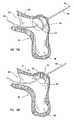
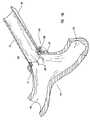
- FIG. 1is a partially cut-away view of the general disposition of the intraluminally directed anvil apparatus, wire and endoscopic or peripheral device of this invention.
- FIG. 2Ais a partial cut-away view of one of the ends of the catheter shown in FIG. 1 .
- FIG. 2Bis a partial cut-away view of another embodiment of one of the ends of the catheter depicted in FIG. 1 .
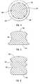
- FIG. 3Ashows an embodiment of the anvil of this invention that is attached to the wire with the aid of two stoppers.
- FIG. 3Bshows another embodiment of the anvil of this invention that is integrally attached to the wire and has concave side features on its surface.
- FIG. 3Cshows another embodiment of the anvil of this invention that is integrally attached to the wire and has side surface features for bending staples or clips.
- FIG. 3Dshows another embodiment of the anvil of this invention that is integrally attached to the wire and has another set of side surface features for bending staples or clips.
- FIG. 4is a cross sectional view along plane 4 of the anvil shown in FIG. 3B .
- FIG. 5is a cross sectional view along plane 5 of the anvil shown in FIG. 3C .
- FIG. 6is a cross sectional view along plane 6 of the anvil shown in FIG. 3D .
- FIG. 7Ais a perspective view of an embodiment of the anvil of this invention with a slanted receiving surface.
- FIG. 7Bshows a cross sectional view of an embodiment of a balloon anvil of this invention.
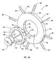
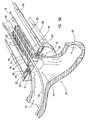
- FIG. 8shows an exploded view of an embodiment of the peripheral device of this invention.
- FIG. 9Ashows an exploded view of an embodiment of the staples, anvil, anastomosis ring and staple guide ring of the embodiment of the peripheral device shown in FIG. 8 .
- FIG. 9Bshows another exploded view of the embodiment shown in FIG. 9A , when the perspective view is offered from the opposite side to that shown in FIG. 9A .
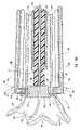
- FIG. 10is a schematic perspective view of the embodiment of the peripheral device shown in FIG. 8 in an assembled configuration.
- FIG. 11shows a side view of the embodiment shown in FIG. 10 .
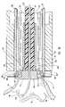
- FIG. 12is a longitudinal cross sectional view of the embodiment shown in FIG. 11 along plane 12 .
- FIG. 13is a magnified view of the region indicated by arrow 13 in FIG. 12 .
- FIG. 14is a cut away perspective view of the region shown in FIG. 13 .
- FIG. 15Ashows an embodiment of the anvil of this invention abutting the receiving blood vessel from the receiving blood vessel's intraluminal space.
- FIG. 15Bshows a cross sectional view of an embodiment of the anvil of this invention abutting the receiving blood vessel at the contact region of the receiving surface of the anvil with the intima of the receiving blood vessel.
- FIG. 15Cis a partial perspective view of the embodiment of the peripheral device shown in FIG. 7 showing part of the graft vessel in the peripheral device, the receiving blood vessel abutted by the anvil, and the wire piercing the receiving blood vessel and extending longitudinally within and along the peripheral device.
- FIG. 15Dis a cut away perspective view of an end of the peripheral device shown in FIG. 15C holding the graft vessel in contact with the receiving vessel at the anastomosis site.
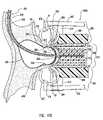
- FIG. 15Eis a longitudinal cross sectional view of the embodiment shown in FIG. 15D at a stage when the graft vessel is being attached to the receiving blood vessel.
- FIG. 15Fis a perspective view like the view shown in FIG. 15D at another stage in the process of attaching the graft vessel to the receiving blood vessel.
- FIG. 15Gis a longitudinal cross sectional view of the embodiment shown in FIG. 15F with the graft vessel attached to the receiving blood vessel.
- FIG. 15His a perspective view like the view shown in FIG. 15F showing the opening of the anastomosis fenestra according to one embodiment of this invention.
- FIG. 15Iis a longitudinal cross sectional view of the embodiment shown in FIG. 15H showing the anastomosis fenestra open in the receiving blood vessel.
- FIG. 15Jis a longitudinal cross sectional view like the one shown in FIG. 15I showing the anastomosed structures and an embodiment of the peripheral device of this invention being pulled away from the anastomosis site.
- FIG. 15Kis a longitudinal cross sectional view like the one shown in FIG. 15J showing the anastomosed structures according to one of the embodiments of this invention.
- FIG. 15Lshows a perspective cut away view of the anastomosed structures shown in FIG. 15K .
- FIGS. 16A–16Hshow a variety of embodiments of the staples and clips of this invention.
- FIG. 17Ashows a cross sectional view of another embodiment of the intraluminally directed anvil apparatus with a deflated balloon anvil.
- FIG. 17Bshows a cross sectional view of the embodiment shown in FIG. 17A where the balloon anvil is inflated and abutting the receiving blood vessel.
- FIG. 17Cshows a cross sectional view of the embodiment of the intraluminally directed anvil apparatus shown in FIGS. 17A–17B while being operated in conjunction with a spring clip anastomosis device.
- FIG. 17Dshows a front view along the logitudinal axis of an embodiment of a spring clip anastomosis device like that shown in FIG. 17C .
- FIG. 17Eshows a perspective view of the embodiment depicted in FIG. 17D .
- Plane S–S′represents the plane along which the cross sectional views shown in FIGS. 17C , 17 F– 17 I are taken.
- FIG. 17Fis a cross sectional view analogous to that shown in FIG. 17C while the anastomosis fenestra is being opened with a laser device, where the cross section is taken along the plane S–S′ shown in FIG. 17E .
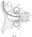
- FIG. 17Gis a cross sectional view analogous that shown in FIG. 17F with an anastomosis fenestra in the receiving blood vessel.
- FIG. 17His a cross sectional view analogous that shown in FIG. 17G with the spring clips holding together the receiving blood vessel and the graft vessel.
- FIG. 17Iis a cross sectional view analogous to that shown in FIG. 17H after the laser device has been removed from the anastomosis site.
- FIG. 17Jis a cross sectional view analogous to that shown in FIG. 17I after the entire spring clip anastomosis device has been removed from the anastomosis site.
- FIG. 17Kis a cross sectional view of two structures that have been anastomosed with the intraluminally directed anvil apparatus and the spring clip device of this invention.
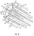
- FIG. 18is a perspective view of the embodiment shown in FIG. 8 where the cutter and centering core have been replaced by a laser device.
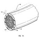
- FIG. 19shows a partial perspective view of the distal end of an exemplary embodiment of a laser device like that generically shown in FIG. 18 .
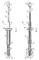
- FIG. 20shows a longitudinal cross sectional view in which the cutter and centering core shown in FIG. 8 have been replaced by a laser device.
- FIG. 21shows a longitudinal cross sectional view analogous that shown in FIG. 20 with an applicator for a material such as solder or glue, and a different way of holding the end of the graft vessel to be anastomosed.
- a materialsuch as solder or glue
- the present inventionrelates to systems, methods and apparatuses for intraluminally directed active endoscopic or peripheral procedures, and more particularly to systems, methods and apparatuses for performing intraluminally directed minimally invasive vascular anastomosis.
- this inventionprovides for the direct utilization of the information acquired during an initial angiographic exploration in the actual creation of an anastomosis. Accordingly, this invention enables the determination of an optimal anastomosis site with the information acquired during the initial exploration and provides for an active endoscopic or peripheral technique for performing a minimally invasive anastomosis immediately following the initial angiographic exploration and in the same clinical environment.
- Minimally invasive anastomosis according to this inventionis performed with an integrated method and system that relies on intraluminally directed active intervention and active endoscopic or peripheral intervention.
- an anastomosis according to this inventionis performed at a site that is signaled with the aid of an imaging technique and an intraluminally directed anvil apparatus that is embodied in this Figure by catheter apparatus 100 .
- the anastomosisis performed with an anastomosis device shown at 200 that generically and exemplarily represents an embodiment of an extravascular device, whether endoscopic or peripheral device.
- Anastomosis device 200is operated in conjunction with an intraluminally directed anvil apparatus, such as catheter apparatus 100 .
- FIGS. 2–7are directed to features of the intraluminally directed anvil apparatus;
- FIGS. 8–22Ishow different views of structural and operational features of different embodiments of the anastomosis device.
- the intraluminally directed anvil apparatusis embodied by catheter apparatus 100 .
- Catheter apparatus 100comprises tubular shaft 110 , positioning wire or stem 152 , anvil 160 , and piercing wire 150 .
- This embodiment of the intraluminally directed anvil apparatusis referred to as a catheter apparatus.
- Other embodiments of the intraluminally directed anvil apparatus without a tubular shaft such as that shown at 110are disclosed herein. These embodiments are also utilized to signal the location of an anastomosis site and to form an anastomosis in conjunction with an anastomosis device.
- Distal end 112 of tubular shaft 110can be percutaneously introduced in the intraluminal space 190 of receiving blood vessel 99 according to conventional catheterization techniques.
- Catheterization techniquesare described, for example, by Constantin Cope and Stanley Baum, Catheters, Methods, and Injectors for Superselective Catheterization, in Abrams' Angiography , edited by Stanley Baum, 4th ed. (This work will hereinafter be referred to as “ Catheters, Methods, and Injectors ”, and it is hereby incorporated by reference in its entirety).
- Tubular shaft 110is inserted along intraluminal space 190 until distal end 112 reaches the proximity of a blood vessel occlusion or another abnormality that has been detected by a conventional exploration technique.
- piercing wire 150is introduced into tubular shaft 110 through proximal end 114 and it extends along tubular shaft 110 .
- Piercing wire 150is inserted within and along tubular shaft 110 of catheter apparatus 100 so that distal piercing end 154 punctures receiving blood vessel 99 from its intraluminal space and it extends outwardly by protruding at the optimally chosen anastomosis site.
- distal end 154is preferably sharp enough as to be able to puncture the wall of receiving blood vessel 99 from its intima outwards without causing undue tearing around the puncture.
- Piercing wire in the context of this inventionrefers to any thin and elongated device that is used for penetrating the wall of a blood vessel.
- a guidewire suited for inserting both diagnostic and therapeutic cathetersis disclosed in U.S. Pat. No. 4,846,186, which is hereby incorporated by reference in its entirety, and catheters and guidewires for vascular and interventional radiology are disclosed in Catheters, Methods, and Injectors , at 155–174, references which are hereby incorporated by reference in their entirety.
- Piercing wire 150is preferably pointed and sharp to effectively puncture the wall of receiving blood vessel 99 .
- piercing wire 150extends from anvil 160 and positioning wire 162 extends also from anvil 160 , but opposite to piercing wire 150 .
- the combined length of piercing wire 150 and positioning wire 152varies depending on the separation between the insertion site of catheter apparatus 100 and the anastomosis site. For example, this combined length would be approximately 180 cm long, depending on the patient's height, if an anastomosis were to be performed in a blood vessel in the arm such as the brachial artery, and catheter apparatus 100 were inserted into the femoral artery.
- Distal end 112can be modified as shown in FIG. 2 to provide a lateral exit to distal end 154 of piercing wire 150 .
- distal end 112comprises deflecting surface 156 and lateral aperture 158 that guide distal end 154 of piercing wire 150 towards the intima of receiving blood vessel 99 .
- deflecting surface 156is preferably a puncture and abrasion resistant surface.
- distal end 112can be provided with an appropriate marker for imaging the orientation of the aperture at distal end 112 and/or the position of distal end 112 itself.
- radio-opaque markerscan be any of the radio-opaque markers known in the practice of angiography.
- Piercing wire 150is typically radio-opaque itself, although very thin embodiments of this wire are preferably coated with a material such as gold or barium to make them more visible.
- Catheter distal end configurations for directing outwardly an elongated memberhave been disclosed in U.S. Pat. Nos. 4,578,061, 4,861,336, 5,167,645, 5,342,394, and 5,800,450, which are hereby incorporated by reference in their entirety.
- the intraluminally directed anvil apparatussuch as catheter apparatus 100 , comprises an anvil that is placed in intraluminal space 190 .
- the anvil in this inventionis preferably fixed to piercing wire 150 at its proximal end.
- the anvil of this inventioncould be slidably mounted on and around piercing wire 150 , in which case piercing wire 150 and positioning wire 152 are typically an integral wire.
- the anvil of this inventionis embodied by anvil 160 that is integrally attached to and around piercing wire 150 .
- Anvil 160can also be attached to piercing wire 150 with the aid of any other fastening device or devices that retain anvil 160 in a fixed position relative to piercing wire 150 , whether this wire is inserted into or extracted from intraluminal space 190 .
- Stoppers 180 shown in FIG. 3Aare an exemplary embodiment of fastening devices that facilitate the effective pushing on anvil 160 as positioning wire 152 and piercing wire 150 are inserted through proximal end 114 of tubular shaft 110 and facilitate also the extraction of anvil 160 as positioning wire 152 is pulled out, thus extracting piercing wire 150 through proximal end 114 of tubular shaft 110 .
- the anvil of this inventionprovides a receiving surface, such as receiving surface 162 of anvil 160 , destined to be in direct contact with the blood vessel's intima at the anastomosis site when the anvil abuts the receiving blood vessel wall.
- Anvil 160is sized so that it can slide within the lumen of tubular shaft 110 while presenting a receiving surface 162 that has an area approximately matched to the cross-sectional area of the lumen of the graft blood vessel.
- Anvil 160 and particularly receiving surface 162are preferably made of a puncture resistant material that can withstand the abrasive action of the pointed end of a device that bends upon having its pointed end deflected by receiving surface 162 .
- anvil 160is preferably made of stainless steel when it is to withstand the abrasive action of a cutting device or of a sharp pointed end.
- the anvil of this inventionis preferably coated with radiation absorbing material that prevents radiation scattering.
- Such coated anvil embodimentsare hereinafter referred to as a “laser shield anvil”.
- the anvil of this inventiondoes not have to be puncture resistant when the anastomosed structures are joined in a way that does not require staples, such as clipping, gluing, welding or soldering. This embodiment of the anvil of this invention is hereinafter referred to as a “soft anvil”.
- the anvilis made of expandable material so that the deflated anvil can optionally be moved within and along catheter apparatus 100 and it can be inflated at the anastomosis site.
- This embodiment of the anvil of this inventionis hereinafter referred to as “balloon anvil”.
- a coating of laser shield materialcan be incorporated particularly at the receiving surface of the anvil of this invention.
- a laser shield materialis a shield consisting of a sandwich of polymethylmethacrylate and tinfoil that is known to provide corneal and retinal protection from inadvertent injury during argon, Nd—YAG or dye laser treatment at the tested laser power outputs.
- receiving surface 162is destined to provide a stopping surface for a cutting blade and deflecting surface 164 of anvil 160 is destined to receive the ends of staples that bend upon being deflected by deflecting surface 164 .
- Deflecting surface 164 and receiving surface 162can in some embodiments of anvil 160 be differentiated as two parts of anvil 160 , whereas in some embodiments deflecting surface 164 is a continuation of receiving surface 162 .
- the terms “receiving surface” and “deflecting surface”will collectively refer to the surface of anvil 164 .
- receiving surface 162is preferably different from those of deflecting surface 164 when the anvil of this invention is embodied, for example, by a balloon anvil. In other embodiments of this invention, however, receiving surface 162 and deflecting surface 164 are made of the same materials and/or have similar features.
- deflecting surface 164 of anvil 160can be smooth, or it can be provided with depressions as shown in FIGS. 3B–3D .
- These depressionsare formed with the appropriate shape for deflecting a pointed end such as the pointed end of a needle or a staple, and they can include a variety of concave shapes such as depressions 165 and 166 , or a combination of concave and convex shapes such as in 167 .
- FIGS. 4 , 5 and 6show cross sections along the lines 4 – 4 ′, 5 – 5 ′ and 6 – 6 ′, respectively of the embodiments of the anvil shown in FIGS. 3B–3D .
- receiving surface 162is schematically shown in FIGS. 1–6 as a flat surface that is perpendicular to the longitudinal axis of each one of the embodiments of the anvil of this invention
- other embodimentsmay have a slanted receiving surface such as surface 168 when the anvil abutting the wall of the receiving blood vessel has to cooperate in the formation of, for example, a bevelled anastomosis.
- This shape of an embodiment of anvil according to this inventionis schematically illustrated in FIG. 7 .
- outer perimeter of a cross section perpendicular to the longitudinal axis of an embodiment of an anvil according to this inventioncan be shaped in anyone of a plurality of curved figures, such as a circumference, an ellipse, an ovoid, and combinations of arcuate portions.
- Receiving surfaces 162 and 168can additionally, or alternatively, provide an absorbing medium for radiation directed against it. Radiation to which receiving surfaces 162 and 168 might be exposed to is radiation from one of the laser sources typically used in surgical procedures. Materials that absorb this type of radiation have been discussed hereinabove.
- base 170 of the anvil of this inventiondoes not necessarily have to form a flange or ledge at the edge of a broad and generally flat surface, but it can also be shaped with smooth rounded edges, have a shape generally symmetrical to that of receiving surface 162 , or be shaped in a combination of curved and/or straight contours. Shapes of base 170 such as those shown in FIGS. 3D , 6 and 7 A can be more useful for diminishing the drag while the anvil is moved within and along the receiving blood vessel.
- the anvil of this inventioncan be embodied by a puncture resistant balloon. Puncture and scratch resistant balloons have been disclosed in U.S. Pat. Nos. 5,766,158, 5,662,580, 5,620,649, 5,616,114, 5,613,979, 5,478,320, 5,290,306, and 5,779,731, which are hereby incorporated by reference in their entirety.
- the anvil of this inventioncan be embodied by the combination of a balloon and a puncture resistant balloon sheath. A balloon plus balloon sheath combination has been disclosed in U.S. Pat. No. 5,843,027 which is hereby incorporated by reference in its entirety.
- any of the embodiments of the anvil of this inventionare determined by the size of the lumen of the receiving blood vessel and by the dimension of the passage that will ensure the fluid communication between the graft vessel and the receiving vessel after they have been anastomosed.
- the inclination of receiving surface 168 in an embodiment of the anvil of this invention as schematically shown in FIG. 7is appropriately chosen depending on the diameter of the graft vessel and on the angle at which the graft vessel is to be anastomosed to the receiving blood vessel. These dimensions are known to anyone with ordinary skill in the art.
- the anvil of this inventionwhen the anvil of this invention is embodied by a device as one shown in any of FIGS. 3A–3D and a graft vessel of about 4 mm in diameter is to be anastomosed to a receiving vessel with an approximate lumen diameter of about 8 mm, the height from base 170 to receiving surface 162 can typically range from about 3 mm to about 4 mm, and the diameter of a cross section parallel to receiving surface 162 can typically range from about 3.5 mm to about 4.5 mm.
- the methods, systems and apparatuses of this inventionare preferably used for anastomosing graft vessels whose diameter ranges between about 2 mm and about 20 mm, but there is no fundamental limitation for using embodiments of this invention with graft vessels whose diameter is less than 2 mm.
- any of the exemplary embodiments of the anvil of this inventionis made is appropriately chosen to be abrasion resistant, puncture resistant, distortion resistant and/or an effective absorber of radiation depending on whether it is to be exposed to the abrasive action of a cutting device, to the perforating action of a sharp pointed end, to the twisting or distorting action of a gripping device, or to radiation.
- a cutting devicecan be, for example, a cutting blade; a sharp pointed end can be, for example, the penetrating end of a staple or the sharp end of a needle; a gripping device can be, for example, a clip, and radiation can be emitted by, for example, a surgical laser.
- the proximal end of the intraluminally directed apparatus of this inventioncan comprise one or a plurality of access ports or luer fittings.
- only one access portis shown in the embodiment of catheter apparatus 100 schematically shown in FIG. 1 .
- the embodiment of catheter apparatus 100 as schematically shown in FIG. 1only displays one lumen, but catheter apparatus 100 , and more generally the intraluminally directed anvil apparatus, can also have a plurality of lumens.
- the manufacture and handling of an apparatus with a plurality of lumens and a plurality of access portsare part of the ordinary skill in the art.
- U.S. Pat. Nos. 5,662,580 and 5,616,114which have herein been incorporated by reference in their entirety, disclose catheters with a plurality of access ports or luer fittings and a plurality of lumens.
- Dilation of balloon anvil 560 from its collapsed configuration shown in FIG. 17A to its expanded configuration shown in FIG. 17Bis accomplished by conventional methods and implements such as inflation with the aid of an additional inflation lumen (not shown in FIGS. 17A and 17B ).
- balloon anvil 560is hereinbelow described as being “inflated” or “deflated”, this terminology merely illustrates one possible way of expanding and contracting an embodiment of the balloon anvil of this invention.
- Deflated balloon anvil 560is inserted into the intraluminal space of receiving blood vessel 99 as shown in FIG. 17A and it is inflated at the anastomosis site so that receiving surface 562 of balloon anvil 560 abuts the wall of receiving blood vessel 99 from its intraluminal space.
- Receiving surface 562is preferably made of a laser absorbing material when the anastomosis fenestra is to be opened by laser radiation.
- the structure of the wall of balloon 560is such that groove 564 forms when balloon anvil 560 is inflated as shown in FIG. 17B .
- Balloon anvil 560 , positioning wire 550 , and piercing wire 554are provided with an engagement feature that can be embodied by an attachment 563 as shown in FIGS. 17A and 17B .
- Attachment 563can be embodied by any other engagement feature that prevents balloon anvil 560 to slide along positioning wire 550 when extravascular pressure is applied against receiving blood vessel 99 and receiving surface 562 .
- balloon anvil 560Another preferred characteristic of balloon anvil 560 is that its dimensions and shape are such that, when inflated, balloon anvil 560 will provide an effective fluid tight seal at the anastomosis site, so that the anastomosis can be performed without interruption of blood flow along the lumen of receiving blood vessel 99 .
- piercing wire 554has a distal piercing end, like piercing distal end 154 of piercing wire 150 , which is sharp enough to pierce the wall of receiving blood vessel 99 at the abutted portion 566 .
- an inflatable balloonis provided as shown in FIG. 7B with a surface feature that is shaped like the combination of receiving surface 162 and deflecting surface 164 .
- This featureis formed on the surface of the balloon and it is destined to abut the receiving blood vessel wall as any other of the embodiments of the anvil of this invention does.
- This inflatable balloonis preferably attached to a multilumen catheter with expansion/contraction lumen 181 for inflating and deflating the balloon, positioning shaft 182 for housing the balloon insertion guide wire, and piercing shaft 183 for housing the piercing wire.
- Piercing shaft 183is curved within the balloon towards and through the anvil formed on the balloon surface so that it provides a passage that directs the piercing wire towards the intima of the receiving blood vessel.
- this balloon anvilcan be designed so that the blood flow through the receiving blood vessel will preferably not be interrupted during the anastomosis.
- the designcan be such that the blood flow is interrupted when this feature is desired.
- the balloon anvil shown in FIG. 7Bis designed so that it completely occludes the blood flow within receiving blood vessel 99 . With this design, the wall of receiving blood vessel 99 is abutted by the anvil when the balloon anvil is inflated even if the balloon anvil is not attached to the piercing wire.
- anvilin the context of this invention is meant to encompass balloon anvils.
- the intraluminally directed anvil apparatus of this inventioncomprises a piercing wire, a conduit for housing this piercing wire, and an anvil. Consequently, a balloon anvil is understood as an anvil whose base is so modified as to be able to be expanded and contracted by, for example, inflation and deflation.
- the terms “balloon anvil”will still be used when referring to a specific embodiment such as the one shown in FIG. 7B .
- the herein disclosed exemplary embodiments of intraluminally directed anvil apparatus of this inventionare introduced into the receiving blood vessel and subsequently positioned at the anastomosis site according to different techniques.
- a catheteris introduced into the receiving blood vessel with the aid of a guide wire, which is removed once the catheter is properly positioned.
- a piercing wire with an anvil attached theretois introduced and placed at the anastomosis site.
- This procedurecan also be used to properly place a balloon anvil as shown in FIG. 7B .
- positioning lumen 182can be omitted or it can be used in conjunction with the guide wire.
- a piercing wireis introduced within and along piercing shaft 183 of the embodiment shown in FIG. 7B to pierce the wall of the receiving blood vessel at the anastomosis site.
- a deflated balloon anvilsuch as the embodiment shown in FIG. 7B can optionally be directly introduced into the receiving blood vessel along a guide wire that is housed in positioning lumen 182 without resorting to the passage of the balloon anvil within and along any other additional foreign tubular structure such as tubular shaft 110 of catheter 100 . With the balloon anvil so positioned and inflated at the anastomosis site, the receiving blood vessel is then pierced with a piercing wire.
- the length of wire 150 that extends outside the receiving blood vesselsignals the chosen anastomosis site.
- This wireis used for cooperatively performing the anastomosis of a graft vessel with anastomosis device 200 .
- FIGS. 8–14Another example of an anastomosis device is shown in FIGS. 8–14 as a peripheral device whose primary components comprise centering core 207 , cutter 213 , staple pushing device 219 , activation sheath 233 , staples 308 , and two rings: staple guide ring 300 and anastomosis ring 350 .
- Distal end 154 of wire 150is introduced in the embodiment shown in FIG. 8 through anastomosis ring 350 , staple guide ring 300 and through conduit 205 that extends coaxially within centering core 207 from its distal coupling end 209 to its proximal control end 211 .
- the length of wire 150 that extends outside the receiving blood vesselis sufficient to allow distal end 154 to sufficiently project beyond proximal control end 211 for an operator to be able to hold and pull wire 150 from the region near distal end 154 .
- proximal control end 211comprises a “flow switch” 212 as exemplarily shown in FIGS. 11 and 12 .
- a flow switchis a device that provides a releasable locking mechanism. Flow switches are well known commercially available devices. One example of such device is the flow switch that is marketed under the name FloSwitch by Boston Scientific Corporation. Other devices that provide a locking mechanism can be used instead of flow switch 212 .
- centering core 207is coaxially aligned within hollow cutter 213 , whose length from proximal end 215 to distal cutting end 217 is less than the length of centering core 207 from its proximal control end 211 to its distal coupling end 209 .
- Distal cutting end 217is provided in this exemplary embodiment of the invention with a sharp cutting edge along the entire perimeter of the generally cylindrical cutter 213 at cutting end 217 .
- distal cutting end 217is made of metals or alloys that are suitable for providing such sharp cutting edge and/or distal cutting end 217 can be coated with a material or materials that prevent the tissue being cut from adhering onto it. An example of such material is teflon.
- Centering core 207is shown in FIG. 8 as a solid core with conduit 205 extending coaxially therethrough.
- centering corecan be embodied by an axially extending tube, guide or any other similar passage that provides a housing for extending the piercing wire therethrough.
- staple engaging device 219comprises a hollow cylindrical portion 221 at its proximal end 223 .
- This hollow cylindrical portion 221facilitates the coaxial fitting of staple engaging device 219 and it provides support in this particular embodiment to staple pushing arms 225 and to retention arms 228 .
- Both staple pushing arms 225 and retention arms 228extend from their respective proximal ends 226 and 229 to their respective distal pushing ends 227 and retention ends 230 .
- FIGS. 8 and 9Ceight pushing arms and eight retention arms are shown in the exemplary embodiment depicted in FIGS. 8 and 9C and consequently the numbers of troughs 310 and notches 322 in anastomosis ring 350 and the numbers of staple grooves 302 and notches 320 in staple guide ring 300 are also eight, other embodiments of the anastomosis device of this invention may rely on more or less than eight of any of these corresponding elements. Reliance on less than eight staples with their corresponding troughs 310 and staple grooves 302 may be adequate when the anastomosed structures are joined by the combined effect of a mechanical device such as staples or clips and radiation welding, gluing or soldering. Reliance on more than eight staples with their corresponding troughs 310 and staple grooves 302 may be suitable for the larger anastomosed structures whose joining is performed with staples only.
- a mechanical devicesuch as staples or clips and radiation welding, gluing or soldering
- Each retention arm 228is generally disposed longitudinally from its proximal end 229 to its retention end 230 approximately parallel to the longitudinal axis of centering core 207 and cutter 213 .
- each staple pushing arm 225is tension loaded so that, absent a constraint, the locus of each distal pushing end 227 will be part of an approximately circular perimeter whose diameter is greater than the diameter of the approximately circular perimeter that is defined by the locus of each retention end 230 .
- Proximal ends 226 and 229 of staple pushing arms 225 and retention arms 228are respectively attached to affixing end 231 of hollow cylindrical portion 221 .
- Proximal ends 226 and 229are preferably integrally attached to affixing end 231 , but they can also be affixed to affixing end 231 by welding or with the aid of a fastener. Alternatively, proximal ends 226 and 229 can be integrally attached to a mount that threadably engages preferably the inner surface of hollow cylindrical portion 221 at affixing end 231 . In a preferred configuration of the embodiment of this invention shown in FIG. 8 , the distance from proximal end 223 of the hollow cylindrical portion 221 to any distal pushing end 227 is such that staple engaging device 219 is slightly shorter than cutter 213 .
- retention arms 228could in other embodiments of this invention be attached by their proximal ends to a hollow cylindrical portion.
- pushing arms 225could be attached by their proximal ends to another generally co-axial and independent cylindrical portion.
- Each distal pushing end 227preferably has a feature that aids in the effective driving by distal pushing end 227 of a staple or similar fastening device.
- This featurecan be an indentation such as indentation 241 shown in FIG. 8 , a series of indentations, an arcuate or hooked feature or any other feature that is suitable for this purpose and whose design is part of the ordinary skill in the art.
- the embodiment shown in FIG. 8also comprises activation sheath 233 that is coaxially disposed outside and around staple engaging device 219 .
- Activation sheath 233is shorter than any staple pushing arm 225 or retention arm 228 .
- sleeve 235extends from guiding distal end 236 to handling proximal end 237 , which in turn extends outwardly as flange 238 .
- flange 238extends along the entire perimeter of handling proximal end 237 that is preferably and generally shaped like a circumference.
- the purpose of flange 238is to aid in the handling of activation sheath 233 , and in particular to aid in the sliding back and forth of activation sheath 233 . Consequently, it is understood that flange 238 can be shaped in any of a plurality of shapes that are not shown in FIG. 8 .
- flange 238can be embodied by a pair of approximately opposed flat flanges, handles, or by a pair of approximately opposed rings.
- syringesat or near the end through which the syringe piston is inserted and no further discussion of such features or their equivalents is provided because they and their forms of attachment to sleeve 235 are within the ordinary skill in the art.
- a groove along the perimeter of proximal end 237can provide in other embodiments of activation sheath 233 the necessary grip for pushing or pulling activation sheath 233 .
- an activation sheath 233 with a smooth outer surface of sleeve 235 or with rugosities in outer surface of sleeve 235 as shown in FIG. 8can still be part of an embodiment of activation sheath 233 with no flange 238 .
- activation sheath 233causes distal pushing end 227 of each staple engaging device 219 to move radially inwards. This is predominantly achieved by the slidable engagement of inner surface 239 of guiding distal end 236 with each staple pushing arm 225 .
- indentations or grooves in inner surface 239facilitate the slidable engagement of inner surface 239 with each staple pushing arm 225 .
- FIGS. 8 , 9 A– 9 Calso comprises staple guide ring 300 and anastomosis ring 350 .
- a plurality of staple grooves 302are disposed in retention side 303 , preferably equally spaced and radially extending from outer side wall 304 to inner side wall 306 of staple guide ring 300 .
- a staple 308slides within each staple groove 302 upon being driven radially inwards from outer side wall 304 to inner side wall 306 by each distal pushing end 227 .
- a plurality of troughs 310are preferably disposed in anastomosis ring 350 , each corresponding with a staple groove 302 .
- Each trough 310is perforated by preferably two staple prong passages 311 extending radially from outer side wall 312 to inner side wall 314 .
- Anastomosis ring 350is so dimensioned that it concentrically fits within the space limited by inner side wall 306 of staple guide ring 300 .
- each staple 308can radially slide upon being driven by distal pushing end 227 acting on driving portion 309 .
- Each staple 308thereby slides along each staple groove 302 so that each staple prong 307 moves radially inwards along a corresponding staple prong passage 311 .
- each puncturing end 305inwardly protrudes through each corresponding staple prong passage opening 311 into the space defined by inner side wall 314 .
- a deflecting surfacesuch as any of surfaces 164 – 167 of an anvil such as any of the embodiments of an anvil shown in FIGS. 3–7 will cause each staple prong 307 to bend according to the shape imposed by the deflecting pattern which in turn is determined by the geometric features of the deflecting surface. A few examples of such geometric features are shown in FIGS.
- a plurality of notches 320are preferably equally spaced along the inner perimeter of staple guide ring 300 .
- Anastomosis ring 350can be shaped in any one of a variety of equivalent configurations that can be designed with the aid of ordinary skill in the art consistently with the purposes of the anastomosis ring of this invention. These purposes include providing support to the structures being anastomosed, providing support to the staples being driven through the vessels, causing the anastomosed structures to conform around the anvil of this invention if an anvil is used, and forcing the surfaces of the graft vessel and the receiving blood vessel against each other.
- Anastomosis ring 350is preferably made of titanium, but it can also be made of any other biocompatible material that is resilient enough to perform according to the purposes of the anastomosis ring of this invention.
- anastomosis ring 350can be made of the same materials of which coupling anastomosis devices are made.
- the anastomosis ringis a removable ring that can be taken away from the anastomosed structures once they have healed into a leak-proof joint.
- Staple guide ring 300 and anastomosis ring 350are preferably held with respect to each other in a concentric and fixed position. This is preferably achieved in the embodiment shown in FIGS. 8 , 9 A– 9 C with the aid of a plurality of notches 320 and 322 which are best viewed in FIG. 9B .
- Notches 320are disposed in inner side wall 306 of staple guide ring 300 , preferably equally spaced on retention side 303 .
- Notches 322are disposed in inner side wall 314 of anastomosis ring 350 , preferably equally spaced on retention side 324 and corresponding with respective notches 320 in staple guide ring 300 .
- Each pair of corresponding notches 320 and 322 so disposeddefines a retention slot that receives retention end 230 of retention arm 228 .
- staple guide ring 300 and anastomosis ring 350are concentrically fixed with respect to each other to permit the sliding of staples 308 along staple grooves 302 into troughs 310 and through staple prong passages 311 .
- Staple guide ring 300 and anastomosis ring 350 as shown in FIGS. 8 and 9 A– 9 Care mating structures with outer side wall 312 of anastomosis ring 350 destined to be in contact engagement with inner side wall 306 of staple guide ring 300 .
- these two ringscan be aligned with respect to each other with the aid of mating keys on one of the rings and slots on the other ring.
- the key or keys in these keyed ringsare located on inner side wall 306 of staple guide ring 300 and the mating slots are located on outer side wall 312 of anastomosis ring 350 .
- the key or keysare located on outer side wall 312 and the mating slots are located in inner side wall 306 .
- One or a plurality of keyscan be used for aligning anastomosis ring 350 and staple guide ring 300 , and these keys can be shaped in the form of protuberances such as lugs, corrugations or other features that can be mated with complementary features such as slots or indentations.
- anastomosis device 200can operate with no reliance on anastomosis ring 350 .
- staples 308are delivered directly from staple guide ring 300 that more tightly fits around graft vessel 98 near its partially everted end 97 .
- staples 308are preferably inserted through staple prong passages that allow the driving portion of each staple to reach or almost reach inner sidewall 314 of anastomosis ring 350 .
- the staplesare preloaded in an anastomosis ring that is hereinafter referred to as “preloaded anastomosis ring”, in which case the anastomosis can be performed with no reliance on staple guide ring 300 .
- anastomosis device 300one of a variety of biocompatible anastomosis rings that are eventually dissolved is used as the anastomosis ring.
- one of such dissolvable materialsis marketed by Boston Scientific Corporation under the name TempTip.
- the dissolvable rings manufactured according to the inventionpreferably comprise a bioabsorbable material, which can be absorbed over time and replaced with living tissue.
- An example of a preferred bioabsorbable material that could be used to manufacture the bioabsorvable rings of the present inventionis a poly-l-lactic acid polymer, also known as “PLLA”.
- Other bioabsorbable materials known in the artare described in detail in U.S. Pat. No. 4,643,734, which is hereby incorporated by reference in its entirety.
- staple guide ring 300 and that of anastomosis ring 350 shown in FIG. 9correspond to rings with generally circular features, in which case the rings are referred to as “circumferential rings”, these rings and their lumens 327 and 328 , respectively, can be shaped in other curved shapes, such as ellipsoidal, ovoidal or with a combination of arcuate features. These rings are hereinbelow referred to as “non-circumferential rings”.
- staple grooves 302 , troughs 310 , and staple prongs passages 311as shown in FIG.
- rings 300 and 350are termed “orthogonal rings”.
- these elementscan be arranged in the embodiments of this Example so that the stapled sites generally define a plane that is not orthogonal to the longitudinal axis of centering core 207 .
- These configurationsmay be particularly useful in the practice of bevelled anastomoses. Rings with these configurations are hereinbelow referred to as “non-orthogonal rings”.
- a function performed by the embodiments of the staple guide ring or the anastomosis ring of this inventionis to properly orient the staples according to a predetermined configuration.
- FIG. 10shows a perspective view of the assembled embodiment whose components are shown in FIGS. 8 and 9 .
- a side view of the same embodimentis shown in FIG. 11 , where wire 150 is inserted through the full length of centering core 207 and anvil 160 is inserted into anastomosis ring 350 which in turn is concentrically placed within staple guide ring 300 .
- FIG. 12shows a cross section along plane 12 – 12 ′ as indicated in FIG. 10 of the embodiment whose side view is shown in FIG. 11 .
- FIG. 13shows an enlarged view of region 13 – 13 ′ as indicated in FIG. 12
- FIG. 14shows a perspective view of the area whose cross section is shown in FIG. 13 .
- anvil 160 in FIG. 14shows a series of depressions 169 for deflecting a pointed end.
- FIGS. 15A and 15Bshow an embodiment of the anvil of this invention abutting the wall of receiving blood vessel 99 from intraluminal space 190 .
- FIG. 15Ashows distal end 154 of wire 150 having perforated the wall of receiving blood vessel 99 while surface 162 of anvil 160 contacts intima 191 of receiving blood vessel 99 .
- FIG. 15Bshows a cross section of anvil 160 effectively abutting the wall of receiving blood vessel 99 .
- FIG. 15Cshows a perspective view of the embodiment whose components are shown in FIGS. 8 and 9 with a perspective and cut-away view of receiving vessel 99 and graft vessel 98 with its partially everted end 97 over bottom side 325 of anastomosis ring 350 and bottom side 326 of staple guide ring 300 .
- graft vessel 98can be an autologous blood vessel or a synthetic graft made of biomaterials that have been named in the foregoing discussion of devices and techniques under the general heading Relevant Technology in the Background section of this Specification.
- FIGS. 8 , 10 – 12 with graft vessel 98 disposed as indicated in FIG. 15Cis preferably performed as follows.
- Embodiment 200 Ais approached to the abutted side wall of receiving blood vessel 99 by holding the portion of wire 150 that extends beyond proximal control end 211 .
- the embodiment shown in FIGS. 11–12is slid along wire 150 until the abutted portion of receiving blood vessel 99 is within graft vessel 98 as indicated in the perspective cut-away view shown in FIG. 15D .
- graft vessel 98is generally coaxially disposed outside and around cutter 217 so that it is generally coaxially located between cutter 213 and the set of longitudinally extending retention arms 228 .
- graft vessel 98is partially disposed through anastomosis ring 350 so that the graft vessel's anastomosis end 97 is partially everted on bottom side 325 of anastomosis ring 350 and on bottom side 326 of staple guide ring 300 . Accordingly, the anastomosis ring 350 maintains an end of graft vessel 98 in a desired position for anastomosis.
- FIG. 15Dshows the anvil of this invention abutting the wall of receiving vessel 99 into intraluminal space 96 of graft vessel 98 , near its partially everted end 97 which in turn is surrounded by inner side wall 314 of anastomosis ring 350 . Consequently, the outer wall of receiving blood vessel 99 and the inner wall of graft vessel 98 are in contact with each other while they are held between inner side wall 314 of anastomosis ring 350 and an embodiment of the anvil's surface such as any of surfaces 164 – 167 .
- the stapling action with the exemplary embodiment 200 Ais achieved by sliding activation sheath 233 forward from proximal end 233 of staple engaging device 219 towards distal pushing ends 227 of staple pushing arms 225 .
- This motioncauses distal pushing ends 227 that are engaged with corresponding staple grooves 302 to move radially inwards from outer side wall 304 towards inner side wall 306 , thus forcing staples 308 to slide within anastomosis ring 350 as described in the foregoing discussion, pierce through graft vessel 98 and receiving blood vessel 99 , and staple together anastomosis ring 350 , receiving blood vessel 99 and graft vessel 98 at the anastomosis site.
- This actionis illustrated in FIG.
- FIG. 15Hillustrates the operation of cutting this opening after anastomosis ring 350 , receiving blood vessel 99 and graft vessel 98 have been stapled as shown in FIGS. 15E–15G .
- cuttingis achieved by coaxially inserting cutter 213 until distal cutting end 217 is in contact with receiving blood vessel 99 .
- cutter 213is then preferably turned about its longitudinal axis or pushed with sufficient force from its proximal end 215 so that distal cutting end 217 cuts through the wall of receiving blood vessel 99 until it is stopped by receiving surface 162 of anvil 160 .
- anvil 160is not significantly displaced backwards into the intraluminal space of receiving blood vessel 99 because a portion of wire 150 extending beyond proximal control end 211 is held so as to effectively counteract any pushing caused by cutter 213 .
- centering core 207 , cutter 213 , and staple device 202 with staple engaging device 219 and activation sheath 233are pulled backwards slidably along wire 150 and away from the anastomosis site as shown in FIG. 15J .
- This operationalso leads to the extraction of staple guide ring 300 that is engaged at notches 320 with corresponding retention ends 230 of retention arms 228 .
- the portion 99 A of the abutted wall of receiving blood vessel 99 that is cut upon opening of the anastomosis fenestrais preferably extracted when centering core 207 , cutter 213 , staple engaging device 219 and activation sheath 233 are pulled backwards.
- Thiscan be achieved by applying suction at proximal control end 211 to induce in conduit 205 the necessary rarefaction to cause cut out fragment 99 A of the wall of receiving blood vessel 99 to attach itself to distal coupling end 209 and thus be extracted upon extraction of centering core 207 .
- surface 240 of distal coupling end 209can be provided with a series of axially extending hooked sharp features (not shown in FIG. 15J ) that can attach to and facilitate the extraction of fragment 99 A upon removal of centering core 207 .
- centering core 207is preferably kept in contact engagement with receiving blood vessel 99 and in a fixed position with respect to wire 150 with the aid of a locking mechanism such as a flow switch that is preferably located at proximal control end 211 . Accordingly, centering core 207 is preferably fixed prior to the joining of the structures to be anastomosed and prior to the opening of the anastomosis fenestra. Because the locking mechanism that fixes centering core 207 can be released and re-locked at will several times, one or a plurality of devices with a conduit that can house wire 150 can be approached to the anastomosis site.
- FIGS. 15D–15JThe joining of the structures to be anastomosed is exemplarily shown in FIGS. 15D–15J as an operation that precedes the opening of the anastomosis fenestra.
- the structures to be anastomosedcan be joined after the anastomosis fenestra is opened in the receiving blood vessel.
- FIGS. 15D–15Jexemplarily show that the structures to be anastomosed are joined by stapling and that the anastomosis fenestra is opened with a mechanical device such as a cutter.
- other procedurescan be used in the context of this invention for joining the structures to be anastomosed and for opening the anastomosis fenestra.
- FIGS. 15K and 15Lshow graft vessel 98 anastomosed to receiving blood vessel 99 according to the procedure disclosed in the foregoing discussion of FIGS. 15A–15J .
- anastomosis ring 350is stapled outside and around the anastomosis site and provides support to the anastomosed structures and to staples 308 used in this particular anastomosis procedure.
- Hooked or prebent staples used in these embodimentshave features such as those illustrated in FIGS. 16A–16E and combinations of these or similar features that are not explicitly shown in FIGS. 16A–16E but that are within the ordinary skill in the art may be particularly useful with embodiments of anastomosis device 200 that do not rely on anastomosis ring 350 .
- These types of staplesgenerally have prongs 330 that are shorter than prongs 307 of the corresponding staples 308 .
- Hooked staplesalso have at least one hooked puncturing end 331 instead of merely penetrating puncturing ends 305 .
- Some embodiments of this type of stapleshave a pre-bent prong such as prong 332 .
- Hooked puncturing ends and/or pre-bent prongsfasten and hold instead of merely penetrating the structures through which they are inserted. Accordingly, the hooked or pre-bent staples require upon insertion no bending of their prongs for holding the vessels being anastomosed together.
- Hooked or prebent staplessuch as those exemplarily depicted in FIGS. 16A–16E may be particularly useful when the presence in the intraluminal space of the anastomosed structures of the terminal portions of prongs 307 and the sharp puncturing ends 305 is not acceptable.
- these embodimentswould also be preferred when it is desirable to minimize or avoid damage to the intima of the receiving blood vessel, which may result through the use of staples with puncturing ends 305 .
- the practice of this invention with these described embodimentsrequires the careful determination of the thickness of the graft vessel wall and of the receiving blood vessel wall combined and the subsequent use of hooked staples with the appropriate prong length, so that the intima of the receiving blood vessel is not pierced by the hooked staples.
- anastomosis device 200 of this inventionemploy hooked staples that do not pierce the intima of the receiving blood vessel.
- these embodimentsuse anastomosis ring 350 to provide additional support to the anastomosed vessels at the anastomosis site.
- anastomosisrequires the support of a structure such as anastomosis ring 350 .
- the practice of this invention with these embodimentsinvolves the careful determination or estimation of the combined thickness of three structures: that of the graft vessel wall, that of the receiving blood vessel wall, and that of the support structure, such as the distance between outer side wall 312 and inner side wall 314 of anastomosis ring 350 .
- anastomosis device 200 of this inventionemploy staples or clips that hold and support without the need of being bent upon insertion. Whether the staples are hooked or not, these embodiments of staples predominantly rely on the clipping effect of prongs that spontaneously tend to restore an equilibrium position from which they have previously been distorted, and they are referred to as “memory staples” and “memory clips”, respectively.
- these embodiments of staples and clipsuse a device like that illustrated in FIGS. 8–14 , but staples 308 are replaced by staples with prongs that are curved inwards, such as the staples that are shown for example in FIGS. 16F and 16G .
- These staplesare representative of a class of staples whose prongs 333 have been pre-bent towards each other.
- staples in this classcan have one hooked end or two hooked ends, and prongs 333 can be mostly rectilinear such as those of the staple shown in FIG. 16F or mostly curved such as those of the staple or clip shown in FIG. 16G . It is understood that curved portions can have different curvature degrees in addition to those shown in FIGS. 16F and 16G .
- the pre-bent prongsWhen pre-bent staples slide down staple grooves 302 and their prongs slide down staple prong passages in the anastomosis ring, the pre-bent prongs are slightly distorted so that the space between their ends is widened with respect to the equilibrium separation. To avoid irreversible distortion of the staple's shape, this widening is within the elastic compliance of the material used to manufacture the staples of this embodiment. Staple prong passages in the anastomosis ring of this embodiment are so disposed that the prongs of the staples penetrate the graft blood vessel and part of the receiving blood vessel while the space between the ends of the prongs is widened, but the staples are eventually left essentially free to restore or revert to their undistorted shape.
- Anastomosis ring 350 and in particular staple prong passages 311are, in these embodiments, appropriately modified for elastically distorting the width of the staples and for allowing them to essentially restore to their initial shape.
- Staples and clips used in the context of this inventionare preferably made of titanium, titanium alloys or other biocompatible material.
- the anvilis made of tempered stainless steel, although it can be made of other materials that are appropriately selected for resisting the abrasive action of staples. Selection of the appropriate materials can be made by considering the relative hardness of the material that is to be used for the staples or clips and that of the material to be used for the anvil. For example, known scales of relative hardness, such as the Rockwell B scale, provide useful information for this purpose.
- FIGS. 17C–17KAnother example of an anastomosis device is shown in FIGS. 17C–17K as a peripheral device 200 B hereinafter referred to as a “spring clip anastomosis device” whose primary components comprise laser device 700 , and clipping device 650 , which in turn includes holding arms 652 , sleeve 660 , guiding element 670 , and memory clips 695 .
- FIG. 17Cshows the general disposition of catheter 500 with positioning wire 550 and balloon anvil 560 and spring clip anastomosis device 200 B at the anastomosis site.
- guiding element 670comprises at its anastomosis end a series of sectors 672 which are radially disposed around the periphery of longitudinally extending central lumen 671 ; sectors 672 are separated by slots 674 that are also radially arranged around the periphery of longitudinally extending central lumen 671 .
- the number of sectors and corresponding slotsis eight as shown in FIGS. 17D–17E , but other embodiments can have less than or more than eight sectors and corresponding slots.
- a ledge 676 in each sector 672provides support for a holding arm 652 whose holding end 677 is preferably so shaped as to provide a mating feature 678 with corresponding ledge 676 .
- This mating feature 678can be shaped like a ledge that is complementary to ledge 676 as shown in FIGS. 17D–17E , or as a tooth, lip, flange or any other protuberance that can provide detachable contact engagement with ledge 676 .
- ledge 678can have contact engagement with a feature such as a tooth, lip, or flange in sector 672 that is equivalent to ledge 676 and provides detachable contact engagement with ledge 678 .
- Holding end 677extends generally radially towards the anastomosis site along and within slot 674 to form holding lug 679 .
- Each sector 672is provided with at least one protuberance 680 or an equivalent feature thereof that is located on the same side 682 as the ledge 676 . Two of such protuberances are shown in each slot 674 in FIG. 17D .
- Protuberance 680can be shaped as a flange, lip, elongated lug, handle, or any similar protruding feature.
- memory clip 695can be provided with a notch or a similar feature for detachable contact engagement with lug 679 or any equivalent feature to lug 679 at holding end 677 .
- An embodiment of memory clip 695is shown in FIG. 16H , with memory prongs 333 , and preferably partially penetrating end 334 and pinching end 335 .
- Holding arm 652is spring loaded, so that upon turning holding arms 652 as shown by arrow B (or by turning guiding element 670 in the sense opposite to that shown by arrow B) in FIG. 17D , holding end 677 falls off ledge 676 , thereby disengaging arm 652 from sector 672 and releasing the prong that ends at partially penetrating end 695 of memory clip 334 . When this operation takes place, each one of the memory clips placed in slots 674 is simultaneously released in the same manner.
- optical fibers 702deliver radiation that opens the anastomosis fenestra in receiving blood vessel 99 , as shown in FIG. 17E by arrows 705 .
- the opening of the anastomosis fenestrais being performed prior to the release of memory clips 695 .
- Embodiments of laser device 700generally have a configuration similar to that of laser device 400 as shown in FIG. 20 .
- the embodiment of laser device 400 as shown in particular in FIGS. 17C–17Jextends coaxially along and within sleeve 660 and it comprises a plurality of lumens for optical fibers 702 , for piercing wire 554 , and optionally for a connection (not shown) to a vacuum pump or vacuum line.
- the space between sleeve 660 and laser device 700defines longitudinally extending lumen with an annular cross-section that is configured for receiving graft vessel 98 as shown in FIGS. 17C–17H .
- graft vessel 98that is to be anastomosed is held in place in spring clip anastomosis device 200 B by pinching ends 335 of memory clips 695 and protuberances 680 as shown in FIGS. 17C–17H .
- the removal of protuberances 680 from the space between memory clips 695 and partially everted end 97 of graft vessel 98allows memory clips 695 to pinch or clip graft vessel 98 as memory clips 695 are restored to their equilibrium configurations.
- each memory clip 695slides past each corresponding pair of protuberances 680 .
- each memory clip 695slides past the corresponding protuberance 680 .
- FIGS. 17G–17Ishow holding arms 652 at different stages of their movement towards the anastomosis site while memory clips 695 bring in tight contact engagement the intima of receiving blood vessel 99 and the inner surface of graft vessel 98 .
- This tight contact engagementis achieved in this particular embodiment by the restoring force of memory clip 695 , and by the holding provided by partially penetrating end 334 and pinching end 335 of memory clip 695 .
- FIGS. 17C–17D , 17 F– 17 Ido not show the remaining features of sleeve 660 and holding arms 652 because these features are analogous to corresponding features of the embodiment shown in FIGS. 8 , 10 – 12 , and 15 C. In addition, some of these features are partially shown in FIG. 17E .
- spring clip anastomosis device 200 Bis pulled away from the anastomosis area which is left as shown in FIG. 17J .
- the end of graft vessel 98 opposite to end 97is then further joined, for example, in a subsequent anastomosis, or it is treated according to the practice of the procedure being performed.
- balloon anvil 560is deflated and extracted together with catheter apparatus 500 , leaving eventually the anastomosis site as shown in FIG. 17K .
- Piercing wire 554can be extracted at any convenient time after the anastomosis fenestra has been opened and graft vessel 98 has been joined to receiving blood vessel 99 with memory clips 695 .
- Signaling of the appropriate anastomosis site and the anastomosis itself with the embodiments of this inventioncan be performed without interruption of blood flow within receiving blood vessel 99 .
- the methods, systems and apparatuses of this inventiondo not require a 180° eversion of the end of the graft vessel being anastomosed, but at most partial eversion is only needed.
- an arteryis shunted to a vein with a vessel that channels the blood flow from the artery to the vein.
- This vesselis anastomosed at one end to the artery and at the other end to the vein, and it is used in hemodialysis for extracting and subsequently injecting the blood that is dialyzed.
- Embodiment 200 Ais used for anastomosing the ends of the vessel that provides the artery-to-vein shunt.
- only one end or both ends of the graft vesselcan be anastomosed with embodiment 200 A.
- an end of a graft vesselis anastomosed to the receiving blood vessel while the other end is left open, and another graft is similarly anastomosed at a different site of the receiving blood vessel.
- the open endsare then joined with a sleeve according to standard practice.
- Embodiment 200 Bis also used for anastomosing structures to facilitate hemodialysis in similar fashion as disclosed in Example 1 regarding embodiment 200 A.
- Embodiment 200 Brelies on clips that do not penetrate the walls of the anastomosed structures and consequently are not exposed to the blood flow, a feature that should minimize the risk of clot formation.
- FIGS. 8–14To describe this exemplary embodiment of anastomosis device 200 of this invention, reference is made to FIGS. 8–14 .
- staple engaging device 219 , activation sheath 233 , staple guide ring 300 with staples 308 , and anastomosis ring 350 in the embodiments shown in FIGS. 8–14are replaced by hand suturing or by a suturing device such as the suturing device disclosed for example in U.S. Pat. No. 5,860,992 which has been herein incorporated by reference in its entirety.
- the anvil of this inventionsuch as anvil 160 , provides an abrasion resistant surface that deflects the sharp end of a suturing needle.
- Suturingis a technique that has been practiced for a long time, and its features and characteristics are fairly well known. When compared to one of the anastomosis devices herein disclosed, however, suturing sometimes requires a more invasive procedure, it requires comparatively more intensive and specialized training, and it does not provide for the standardization that would enable a broader group of practitioners to utilize it.
- graft vessel 98is joined to receiving blood vessel 99 with the aid of laser welding.
- Laser radiationsuch as radiation from a Nd—YAG laser is preferably delivered circumferentially for heating at sub-vaporization temperatures to smooth, seal, or weld the structures to the anastomosed.
- laser welding with one of the embodiments of this Examplecan be used in addition to or instead of the use of mechanical devices such as staples, clips, or sutures.
- welding with an embodiment according to this Examplecan be performed prior to the opening of the anastomosis fenestra.
- the welding of the edge of the anastomosis fenestra to the inner wall of graft vessel 98can be used to supplement a significantly reduced number of mechanical devices such as staples, clips, or sutures.
- This weldingcould in fact be the only anastomosis joint when receiving blood vessel 99 and graft vessel 98 are such that welding provides the necessary seal for the anastomosis.
- An advantage of the embodiment according to this Exampleis that welding requires no eversion of the end of graft vessel 98 to be anastomosed. Additionally, laser welding provides a seal between the two vessels.
- centering core 207 and cutter 213are pulled away from the anastomosis site and a laser welding device is inserted in their place until the terminal end of this device is placed near the edge of the anastomosis fenestra. Welding can then proceed by administering the appropriate dosage of laser radiation.
- an embodiment 400 of a laser device according to this Exampleis generally and preferably configured like a catheter or like an endoscope with one or a plurality of lumens.
- laser device 400represents a laser welding device. It is understood that the laser device is preferably provided with a central and axially extending conduit analogous to conduit 205 for accommodating a wire such as wire 150 . This conduit is hereinafter referred to as centering lumen.
- graft vessel 98can be held as shown in FIG. 18 by a ring or by a cylindrical structure in a manner analogous to the way anastomosis ring 350 and staple guide ring 300 hold it in the embodiment shown in FIG. 18 .
- an embodiment according to this Examplecan be provided with a peripheral lumen of annular cross-section extending along the length of an embodiment of laser device 400 such as that shown in FIG. 18 , with the distal end of such lumen appropriately designed for holding graft vessel 98 .
- welding with an embodiment according to this Examplecan take place before the anastomosis fenestra is open, in which case centering core 207 and cutter 213 or an equivalent cutting device can be inserted in place of and subsequently to the use of laser device 400 , as in the exemplary embodiment shown in FIG. 18 .
- any of the embodiments of the anastomosis devicethat are disclosed in the discussion of exemplary embodiments of this invention can further include additional probes extending along the same lumen that is used for delivering the radiation or along another lumen in a suitable probe, whether the radiation is used for sealing, opening the anastomosis fenestra or for any other purpose.
- These additional probesinclude an infrared thermometer or any other type of device that is used for measuring temperature, imaging probes for direct visualization of the anastomosis site, light carriers for illuminating the anastomosis site, fiberoptic biosensors including transducer sensors, all-fiber sensors, and spectrometric sensors, probes such as those used in endoscopic photodynamic therapy, and mechanical devices such as forceps, cutters or retrievers of biological material.
- the transducer biosensorsfurther include optic biosensors which change their own optical properties according to the physical or chemical parameter being tested, such as temperature, pressure, chemical characteristics including pH, O 2 concentration, CO 2 concentration, glucose concentration, immunological agent concentration, and properties related thereto.
- All-fiber biosensorsuse modified tips which are sensitive because of core doping or cladding, or because of having a chemically modified fiber end.
- Parameters tested with all-fiber biosensorsinclude temperature and pH and these biosensors are also used for immunological assays.
- Spectroscopic biosensorstypically rely on measurements of reflectance, fluorescence or absorption for measuring concentration of substances such as O 2 , for drug dosimetry, for reflux monitoring, and for pharmacokinetic measurements.
- pulsed lasersare included among the possible laser radiation sources.
- Example 4To describe the exemplary embodiment of anastomosis device 200 of this invention, reference is made to Example 4.
- graft vessel 98is joined to receiving blood vessel 99 with the aid of non-laser welding radiation, such as radiofrequency radiant energy.
- non-laser welding radiationsuch as radiofrequency radiant energy.
- the characteristic features of embodiments of these Examplesare analogous to the features and modifications introduced in the embodiment shown in FIGS. 8–14 , as discussed Example 4.
- this Examplerelies on radiation, its performance is expected to be comparable to that of the preceding Example.
- the use of radiation for welding as disclosed in this Example or in the preceding Examplemay lead to a simpler anastomosis device because the number of mechanical parts is reduced, but in general clinical devices that deliver radiation are currently more expensive than counterparts that perform comparable tasks by mechanical mechanisms.
- FIGS. 8–15 , 15 A– 15 H, 18 , 19 , and 20the anastomosis fenestra is opened in the wall of receiving blood vessel 99 with the aid of radiation, such as laser radiation.
- FIG. 19shows distal end 140 of an exemplary embodiment according to this Example that can generally and schematically be represented by laser device 400 shown in FIG. 18 .
- Tip 141exposes the ends of optical fibers 142 and grid 143 with openings 144 .
- Optical fibers 142are such that they deliver the appropriate radiation for effectively ablating the perimeter of a generally circular region from the outside of receiving blood vessel 99 , thus cutting open the anastomosis fenestra. Openings 144 provide the suitable rarefaction for retaining by suction the fragments and any product resulting from the ablation, burning, or vaporization caused by the irradiation of the wall of receiving blood vessel 99 . To this effect, openings 144 are the ends of a plurality of conduits, or the screened end of a single conduit, to a vacuum pump or a vacuum line.
- tip 141 of an embodiment according to this Exampleis brought near the anastomosis site in a fashion similar to that described in the foregoing discussion regarding centering core 207 and cutter 213 as illustrated in FIG. 18 .
- an embodiment as shown in FIGS. 8–14is used with an embodiment according to this Example replacing centering core 207 and cutter 213 as shown in the cross-sectional view of FIG. 20 .
- An embodiment according to this Examplepreferably has the general configuration and overall features of the embodiment shown in FIG. 18 as discussed in the context of Example 5.
- an embodiment according to this Exampleis preferably provided with a centering lumen. This is the lumen that is longitudinally occupied by wire 150 in the cross-sectional view shown in FIG. 20 .
- the cauterizing effects of radiationmay offer an advantage over mechanical cutters. As indicated in the discussion of the preceding Example, however, a mechanical cutter is expected to be currently less costly than a device that relies on radiation.
- graft vessel 98is joined to receiving blood vessel 99 with the aid of welding such as laser welding or non-laser welding discussed in Examples 4 and 5, and the anastomosis fenestra is opened with the aid of radiation such as laser radiation, as discussed in Example 6.
- An embodiment according to this Examplepreferably has the general configuration and overall features of laser device 400 shown in FIG. 18 as discussed in the context of Example 4.
- laser device 400is preferably a multilumen probe that comprises radiation guides for cutting and for welding as discussed in Examples 4–6.
- a source of radiationsuch as a laser welding device as described in Example 4
- a soldering materialis supplemented with a soldering material.
- a soldersuch as proteinaceous material is preferably applied to the site where receiving blood vessel 99 is to be joined to graft vessel 98 and then laser light is applied to seal the solder to the tissue surfaces. It has been reported that blood loss is reduced in human PTFE arteriovenous fistulae sealed with solder, Laser Tissue Welding , page 400.
- Solders used in embodiments of this Exampleare preferably biological glues that are based on proteins.
- albuminis used as solder.
- Soldercan be applied to the anastomosis area with an applicator that is built into the laser welding device as shown in FIG. 21 or with an applicator that is separately handled. Whether built as part of a laser welding device or not, clinical solder applicators are devices which, like clinical glue applicators, are well known in the art.
- solderingis enhanced by photoenhancement.
- Photoenhanced laser solderingrelies on a chromophore that is added to the solder to focus light absorption in the solder and thus avoid or reduce radiation damage to the anastomosed vessels.
- Indocyanine greenis a preferred chromophore for enhancing vascular welding with near infrared diode laser.
- An embodiment according to this Examplepreferably has the general configuration and overall features of laser device 400 shown in FIG. 18 as discussed in the context of Example 4 and it more specifically can be represented by laser device 401 shown in FIG. 20 .
- laser device 400can be supplemented with at least one lumen for a solder applicator.
- FIG. 21shows a longitudinal cross section of an embodiment of the end of a laser device near the anastomosis site.
- solder 173is supplied through lumen 174 and it is directed by tip 172 to the contact region 175 between graft vessel 98 and receiving blood vessel 99 .
- glueis delivered in one embodiment of this invention as solder 173 is delivered in the embodiment shown in FIG. 21 .
- Device 179can be one or a plurality of devices that deliver radiation for cutting, sealing or soldering.
- Devices 171represents a cross-sectional view of conduits 144 shown in FIG. 19 and discussed in Example 6, they represent in other embodiments of the invention the guides that deliver radiation for opening the anastomosis fenestra as discussed in Example 7, or, in still other embodiments, a combination of both.
- FIG. 21schematically illustrates an exemplary embodiment of a device that holds graft vessel 98 to be anastomosed. This is accomplished in the embodiment shown in FIG. 21 by tubular graft vessel holder 177 that has a feature or plurality of features that releasably hold graft vessel 98 near its end. In particular, this feature can be penetrating point 178 , but it can be embodied by any other feature that detachably holds graft vessel 98 .
- this Exampleillustrates a feature of the several mechanical, radiation-based and chemical devices discussed in the exemplary embodiments of this invention.
- This featureis the combination of several procedures in the practice of vascular anastomosis according to this invention.
- a mechanical procedure that relies on staples, clips or suturecan be combined with a radiation-based procedure or with a procedure that relies on chemical effects for joining anastomosed structures.
- the plurality of possible combinations used in opening the anastomosis fenestra and/or joining the anastomosed structuresis not described in further detail because these combinations can be performed in light of this disclosure, preferred embodiments and illustrative Examples.
- anastomosis device 200 of this inventionTo describe this exemplary embodiment of anastomosis device 200 of this invention, reference is made to Examples 6 and 7. Whether the anastomosis fenestra is opened with a mechanical device such as cutter 213 or with radiant energy such as with an embodiment according to Example 6, a biocompatible adhesive or glue can be used for sealing graft vessel 98 to receiving blood vessel 99 . After or before the anastomosis fenestra is opened, glue is applied to the anastomosis area around the anastomosis fenestra with an applicator that is built into the device used for opening the anastomosis fenestra or with an applicator that is separately handled.
- Clinical glue applicatorsare devices that, whether designed to be handled separately or as a part of a mechanical or laser guide device, are well known in the art.
- gluecan be delivered to the anastomosis area as solder is delivered and with applicators that are similar to those discussed in the context of Example 8.
- the exemplary embodiment of laser device 401 shown in FIG. 21illustrates a possible embodiment according to this Example in which applicator 174 delivers glue rather than solder 173 .
- FIG. 21schematically shows part of an embodiment according to this Example with a series of devices 171 for delivering radiation, an applicator 174 for delivering glue or solder 173 , and graft vessel 98 held by penetrating point 178 within an annular lumen between graft vessel holder 177 and the anastomosis device of this Example.
- This annular lumenis an exemplary illustration of the annular lumen referred to in Example 4.
- Devices 171 for delivering radiationare preferably optical fibers for delivering laser radiation for opening the anastomosis fenestra.
- Applicator 174 for delivering glue or soldercan comprise a cartridge (not shown) and an applicator mechanism (not shown) for releasing the glue or solder in a controlled manner.
- Partially everted end 97 of graft vessel 98is preferably and temporarily held with the aid of attachment device 177 while the anastomosis is being performed.
- the cartridgecan be a suitably modified syringe similar to the preloaded syringes in which fibrin glue Tissucol is commercially available.
- fibrin gluecan have a dual purpose in the context of this invention because it can be used as an adhesive for sealing graft vessel 98 to receiving blood vessel 99 and alternatively, or in addition, it can be used for its properties as a laser shield to protect tissue from certain laser radiation.
- a number of glues that effectively join anastomosed structuresdo not offer the required degree of biocompatibility and can lead to tissue necrosis.
- any one of a plurality of devicessuch as an anvil formed from a hard material such as tempered stainless steel, a laser shield anvil, a soft anvil, a balloon anvil, a combination of balloon and puncture resistant balloon sheath, an anvil with abrasion resistant material, an anvil with puncture resistant material, an anvil with distortion resistant material, and an anvil with an effective radiation absorbing material are exemplary embodiments of anvils.
- a tempered stainless steel anvilis preferred for ease of use.
- each anvilis an example of anvil means for engaging the intima of the wall of a receiving blood vessel.
- the balloon anvils disclosed hereinare also examples of balloon anvil means for engaging the intima of a receiving blood vessel after being inflated.
- the intraluminally directed anvil apparatus of this inventioncan have one or a plurality of access ports or luer fittings, and it can have one or a plurality of lumens. Additionally some embodiments of the intraluminally directed anvil apparatus can be utilized without a catheter tube to be moved within a blood vessel or other lumen to an anastomosis site.
- Embodiments of the intraluminally directed anvil apparatus of this inventionare provided with a positioning means for intraluminally positioning the anvil at the anastomosis site.
- a positioning meansfor intraluminally positioning the anvil at the anastomosis site.
- this positioning meansare provided by a positioning wire such as wire 152 , by positioning shaft 182 , and in embodiments of a balloon anvil with no positioning lumen such as balloon anvil 500 , by positioning shaft 550 .
- the positioning wire 152 , positioning shaft 182 , and positioning shaft 550are also examples of a positioning stem.
- Memory staples, memory clips, clips, staples with penetrating puncturing ends, staples with hooked puncturing ends, and staples with pre-bent prongs, staples with geometric modifications of the shapes thereof, and combinations thereofare exemplary embodiments of staple means for joining graft vessel 98 to receiving blood vessel 99 of this invention.
- Staple means, suture thread and combinations thereofare examples of means for mechanically joining graft vessel 98 to receiving blood vessel 99 of this invention.
- Biocompatible adhesives or glue, solder, biological procoagulant solution, a combination of a chromophore and solder, and combinations thereofare exemplary embodiments of means for chemically joining graft vessel 98 to receiving blood vessel 99 of this invention.
- Tissue welding radiationsuch as laser radiation or radiofrequency radiation
- the combination of substances and radiation for laser sealing, and combinations thereofare exemplary embodiments of radiation-based means for joining graft vessel 98 to receiving blood vessel 99 of this invention.
- Means for mechanically joining graft vessel 98 to receiving blood vessel 99 , and combinations thereof, means for chemically joining graft vessel 98 to receiving blood vessel 99 , and combinations thereof, radiation-based means for joining graft vessel 98 to receiving blood vessel 99 of this invention and combinations thereof, and combinations of such mechanical means, such chemical means, and such radiation-based means for joining graft vessel 98 to receiving blood vessel 99are exemplary embodiments of the means for joining graft vessel 98 to receiving blood vessel 99 of this invention.
- Circumferential staple guide ringsare exemplary embodiments of the staple guide means for guiding staple means of this invention.
- Circumferential anastomosis ringsorthogonal anastomosis rings, non-circumferential anastomosis rings, non-orthogonal anastomosis rings, pre-loaded anastomosis rings, and combinations thereof are exemplary embodiments of the anastomosis ring means for maintaining an end of a graft vessel in a desired position for end-to-side anastomosis.
- Permanent anastomosis rings, biocompatible dissolvable anastomosis rings, and removable anastomosis ringsare also examples of such anastomosis ring means.
- permanent anastomosis ringsare also examples of anastomosis ring means for maintaining an end of a graft vessel in a desired position and for providing support around the opening formed in the receiving blood vessel after the end of the graft vessel is attached to the receiving blood vessel at the anastomosis site.
- Graft vessel holding tubesas discussed in Examples 8 and 9 are examples of tubular graft vessel holding means for holding an end of a graft vessel in a desired position for end-to-side anastomosis. Such holding tubes are particularly useful when joining is achieved by chemical means or radiation-based means for joining a graft vessel to a receiving blood vessel. Such graft vessel holding tubes as well as anastomosis rings are examples of graft vessel holding devices. Additionally, tubular graft vessel holding means and anastomosis ring means are both examples of graft vessel holding means for holding an end of a graft vessel in a desired position for end-to-side anastomosis.
- Embodiments of the attachment means for attaching the wall of the receiving blood vessel to the end of the graft vessel of this inventioninclude staple delivery means for delivering staple means such as the staple devices disclosed herein for joining the graft vessel to the receiving blood vessel; means for suturing an end of the graft vessel to the wall of the receiving blood vessel such as the suturing devices disclosed herein; means for clipping an end of the graft vessel to the wall of the receiving blood vessel such as the clipping devices disclosed herein; means for radiation welding an end of the graft vessel to the wall of the receiving blood vessel such as the devices for radiation welding disclosed herein and in particular the laser welding devices disclosed in Example 4 and radiofrequency radiation welding devices disclosed in Example 5; means for laser sealing an end of the graft vessel to the wall of the receiving blood vessel such as the laser sealing devices disclosed herein; means for soldering an end of the graft vessel to the wall of the receiving blood vessel such as the devices for soldering disclosed in Example 8; and means for gluing an end of the graft vessel to the
- Centering core 207a centering lumen, an axially extending tube, guide or any other similar passage that provides a housing for extending the piercing wire therethrough and, in general, a conduit disposed for receiving the wire of this invention are exemplary embodiments of the centering means for centering the staple delivery means over the anastomosis site by receiving the piercing wire of an intraluminally directed anvil apparatus.
- a staple delivery deviceis an example of staple delivery means for delivering staple means for joining graft vessel 98 to receiving blood vessel 99 .
- the staple delivery meanscomprises staple engaging means for engaging the staples and activation means for acting on the staple engaging means to enable the staple engaging means to push the staples through the end of the graft vessel, through the receiving blood vessel around the opening in the receiving blood vessel, and through the anastomosis ring means.
- Staple engaging device 219 and functionally corresponding mechanismsare exemplary embodiments of the staple engaging means for engaging staples.
- Activation sheath 233 and functionally corresponding parts in staple delivery devicesare exemplary embodiments of the activation means for acting on the staple engaging means of this invention.
- Exemplary embodiments of the means for anastomosing the wall of the receiving blood vessel with the end of a graft vesselare provided by the set comprising attachment means and cutting means; by the set comprising attachment means, cutting means and centering means; by the set comprising staple delivery means, centering means, anastomosis ring means, and cutting means; by the set comprising clipping means, centering means and cutting means; by the set comprising suturing means, centering means, and cutting means; by the set comprising radiation welding means, centering means and cutting means; by the set comprising laser sealing means, centering means and cutting means; by the set comprising soldering means, centering means and cutting means; by the set comprising gluing means, centering means, and cutting means; and by any of the previously discussed embodiments with additional probes such as sensors and mechanical devices such as forceps, cutters and extractors.
- FIGS. 1–21 and disclosed in the preceding discussionare not meant to be mutually exclusive.
- features of these exemplary embodimentscan be suitably combined to generate embodiments of intraluminally directed anvil apparatus and of anastomosis means that are additional exemplary embodiments of the present invention.
- These additional combinationscan be performed with the aid of the objectives and teachings herein contained and ordinary skills in the art; thus no other combinations are offered as additional explicit examples.
Landscapes
- Health & Medical Sciences (AREA)
- Life Sciences & Earth Sciences (AREA)
- Surgery (AREA)
- Heart & Thoracic Surgery (AREA)
- Engineering & Computer Science (AREA)
- Biomedical Technology (AREA)
- Nuclear Medicine, Radiotherapy & Molecular Imaging (AREA)
- Medical Informatics (AREA)
- Molecular Biology (AREA)
- Animal Behavior & Ethology (AREA)
- General Health & Medical Sciences (AREA)
- Public Health (AREA)
- Veterinary Medicine (AREA)
- Surgical Instruments (AREA)
Abstract
Description
Claims (148)
Priority Applications (2)
| Application Number | Priority Date | Filing Date | Title |
|---|---|---|---|
| US10/706,245US7220268B2 (en) | 1999-04-16 | 2003-11-12 | Methods for anastomosis of a graft vessel to a side of a receiving vessel |
| US11/375,880US8034064B2 (en) | 1999-04-16 | 2006-03-15 | Methods for forming an anastomosis opening in a side of a blood vessel |
Applications Claiming Priority (3)
| Application Number | Priority Date | Filing Date | Title |
|---|---|---|---|
| US09/293,366US6623494B1 (en) | 1999-04-16 | 1999-04-16 | Methods and systems for intraluminally directed vascular anastomosis |
| US10/243,543US20030014064A1 (en) | 1999-04-16 | 2002-09-12 | Anvil apparatus for anastomosis and related methods and systems |
| US10/706,245US7220268B2 (en) | 1999-04-16 | 2003-11-12 | Methods for anastomosis of a graft vessel to a side of a receiving vessel |
Related Parent Applications (1)
| Application Number | Title | Priority Date | Filing Date |
|---|---|---|---|
| US10/243,543ContinuationUS20030014064A1 (en) | 1999-04-16 | 2002-09-12 | Anvil apparatus for anastomosis and related methods and systems |
Related Child Applications (1)
| Application Number | Title | Priority Date | Filing Date |
|---|---|---|---|
| US11/375,880DivisionUS8034064B2 (en) | 1999-04-16 | 2006-03-15 | Methods for forming an anastomosis opening in a side of a blood vessel |
Publications (2)
| Publication Number | Publication Date |
|---|---|
| US20040097994A1 US20040097994A1 (en) | 2004-05-20 |
| US7220268B2true US7220268B2 (en) | 2007-05-22 |
Family
ID=23128792
Family Applications (4)
| Application Number | Title | Priority Date | Filing Date |
|---|---|---|---|
| US09/293,366Expired - Fee RelatedUS6623494B1 (en) | 1999-04-16 | 1999-04-16 | Methods and systems for intraluminally directed vascular anastomosis |
| US10/243,543AbandonedUS20030014064A1 (en) | 1999-04-16 | 2002-09-12 | Anvil apparatus for anastomosis and related methods and systems |
| US10/706,245Expired - Fee RelatedUS7220268B2 (en) | 1999-04-16 | 2003-11-12 | Methods for anastomosis of a graft vessel to a side of a receiving vessel |
| US11/375,880Expired - Fee RelatedUS8034064B2 (en) | 1999-04-16 | 2006-03-15 | Methods for forming an anastomosis opening in a side of a blood vessel |
Family Applications Before (2)
| Application Number | Title | Priority Date | Filing Date |
|---|---|---|---|
| US09/293,366Expired - Fee RelatedUS6623494B1 (en) | 1999-04-16 | 1999-04-16 | Methods and systems for intraluminally directed vascular anastomosis |
| US10/243,543AbandonedUS20030014064A1 (en) | 1999-04-16 | 2002-09-12 | Anvil apparatus for anastomosis and related methods and systems |
Family Applications After (1)
| Application Number | Title | Priority Date | Filing Date |
|---|---|---|---|
| US11/375,880Expired - Fee RelatedUS8034064B2 (en) | 1999-04-16 | 2006-03-15 | Methods for forming an anastomosis opening in a side of a blood vessel |
Country Status (1)
| Country | Link |
|---|---|
| US (4) | US6623494B1 (en) |
Cited By (65)
| Publication number | Priority date | Publication date | Assignee | Title |
|---|---|---|---|---|
| US20010004698A1 (en)* | 1999-04-16 | 2001-06-21 | Blatter Duane D. | Locking compression plate anastomosis apparatus |
| US20040050393A1 (en)* | 2002-09-12 | 2004-03-18 | Steve Golden | Anastomosis apparatus and methods |
| WO2008157283A1 (en)* | 2007-06-14 | 2008-12-24 | Baylor College Of Medicine | Improved vessel anastomosis clips and related methods of use |
| US7547313B2 (en) | 1998-06-03 | 2009-06-16 | Medtronic, Inc. | Tissue connector apparatus and methods |
| US20090222026A1 (en)* | 2008-02-28 | 2009-09-03 | Rothstein Paul T | Surgical fastening clips, systems and methods for proximating tissue |
| US20100036400A1 (en)* | 2008-08-11 | 2010-02-11 | Aboud Emad T | Vascular anastomosis device |
| US7722643B2 (en) | 1999-03-01 | 2010-05-25 | Medtronic, Inc. | Tissue connector apparatus and methods |
| US7744611B2 (en) | 2000-10-10 | 2010-06-29 | Medtronic, Inc. | Minimally invasive valve repair procedure and apparatus |
| US7763040B2 (en) | 1998-06-03 | 2010-07-27 | Medtronic, Inc. | Tissue connector apparatus and methods |
| US20100286705A1 (en)* | 2008-01-31 | 2010-11-11 | Emory University | Vascular access to extra-vascular space |
| US20110017800A1 (en)* | 2009-07-21 | 2011-01-27 | Viola Frank J | Surgical instrument with curvilinear tissue-contacting surfaces |
| US7879047B2 (en) | 2003-12-10 | 2011-02-01 | Medtronic, Inc. | Surgical connection apparatus and methods |
| US7896892B2 (en) | 2000-03-31 | 2011-03-01 | Medtronic, Inc. | Multiple bias surgical fastener |
| US7938840B2 (en) | 1999-04-05 | 2011-05-10 | Medtronic, Inc. | Apparatus and methods for anastomosis |
| US7963973B2 (en) | 1998-06-03 | 2011-06-21 | Medtronic, Inc. | Multiple loop tissue connector apparatus and methods |
| US8029519B2 (en) | 2003-08-22 | 2011-10-04 | Medtronic, Inc. | Eversion apparatus and methods |
| US8034064B2 (en) | 1999-04-16 | 2011-10-11 | Vital Access Corporation | Methods for forming an anastomosis opening in a side of a blood vessel |
| US8088060B2 (en) | 2000-03-15 | 2012-01-03 | Orbusneich Medical, Inc. | Progenitor endothelial cell capturing with a drug eluting implantable medical device |
| US8105345B2 (en) | 2002-10-04 | 2012-01-31 | Medtronic, Inc. | Anastomosis apparatus and methods |
| US8118822B2 (en) | 1999-03-01 | 2012-02-21 | Medtronic, Inc. | Bridge clip tissue connector apparatus and methods |
| US8177836B2 (en) | 2008-03-10 | 2012-05-15 | Medtronic, Inc. | Apparatus and methods for minimally invasive valve repair |
| USD660960S1 (en)* | 2007-07-13 | 2012-05-29 | Carponovum Ab | Rigid parts of an anastomosis device |
| US20120143216A1 (en)* | 2010-12-06 | 2012-06-07 | Laveille Kao Voss | Clip applier having improved hemostasis and methods of use |
| US8211124B2 (en) | 2003-07-25 | 2012-07-03 | Medtronic, Inc. | Sealing clip, delivery systems, and methods |
| US8328828B2 (en) | 2008-08-11 | 2012-12-11 | Board Of Trustees Of The University Of Arkansas | Device for performing an anastomosis |
| US8394114B2 (en) | 2003-09-26 | 2013-03-12 | Medtronic, Inc. | Surgical connection apparatus and methods |
| US8518060B2 (en) | 2009-04-09 | 2013-08-27 | Medtronic, Inc. | Medical clip with radial tines, system and method of using same |
| US8529583B1 (en) | 1999-09-03 | 2013-09-10 | Medtronic, Inc. | Surgical clip removal apparatus |
| US8668704B2 (en) | 2009-04-24 | 2014-03-11 | Medtronic, Inc. | Medical clip with tines, system and method of using same |
| US20140239039A1 (en)* | 2007-05-02 | 2014-08-28 | Endogene Limited | Device and method for delivering shape-memory staples |
| US8858594B2 (en) | 2008-12-22 | 2014-10-14 | Abbott Laboratories | Curved closure device |
| US8893947B2 (en) | 2007-12-17 | 2014-11-25 | Abbott Laboratories | Clip applier and methods of use |
| US8905937B2 (en) | 2009-02-26 | 2014-12-09 | Integrated Vascular Systems, Inc. | Methods and apparatus for locating a surface of a body lumen |
| US8926633B2 (en) | 2005-06-24 | 2015-01-06 | Abbott Laboratories | Apparatus and method for delivering a closure element |
| US8926656B2 (en) | 2003-01-30 | 2015-01-06 | Integated Vascular Systems, Inc. | Clip applier and methods of use |
| US8942829B2 (en) | 2011-01-20 | 2015-01-27 | Medtronic, Inc. | Trans-septal lead anchoring |
| US8956388B2 (en) | 2000-01-05 | 2015-02-17 | Integrated Vascular Systems, Inc. | Integrated vascular device with puncture site closure component and sealant |
| US9050068B2 (en) | 2005-07-01 | 2015-06-09 | Abbott Laboratories | Clip applier and methods of use |
| US9060769B2 (en) | 2000-09-08 | 2015-06-23 | Abbott Vascular Inc. | Surgical stapler |
| US9089311B2 (en) | 2009-01-09 | 2015-07-28 | Abbott Vascular Inc. | Vessel closure devices and methods |
| US9089674B2 (en) | 2000-10-06 | 2015-07-28 | Integrated Vascular Systems, Inc. | Apparatus and methods for positioning a vascular sheath |
| US9144427B2 (en) | 2007-09-06 | 2015-09-29 | Cardica, Inc. | Surgical method utilizing a true multiple-fire surgical stapler |
| US9173644B2 (en) | 2009-01-09 | 2015-11-03 | Abbott Vascular Inc. | Closure devices, systems, and methods |
| US9241696B2 (en) | 2008-10-30 | 2016-01-26 | Abbott Vascular Inc. | Closure device |
| US9271707B2 (en) | 2003-01-30 | 2016-03-01 | Integrated Vascular Systems, Inc. | Clip applier and methods of use |
| US9282965B2 (en) | 2008-05-16 | 2016-03-15 | Abbott Laboratories | Apparatus and methods for engaging tissue |
| US9295469B2 (en) | 2002-06-04 | 2016-03-29 | Abbott Vascular Inc. | Blood vessel closure clip and delivery device |
| US9314230B2 (en) | 2009-01-09 | 2016-04-19 | Abbott Vascular Inc. | Closure device with rapidly eroding anchor |
| US9320522B2 (en) | 2000-12-07 | 2016-04-26 | Integrated Vascular Systems, Inc. | Closure device and methods for making and using them |
| US9332976B2 (en) | 2011-11-30 | 2016-05-10 | Abbott Cardiovascular Systems, Inc. | Tissue closure device |
| US9364209B2 (en) | 2012-12-21 | 2016-06-14 | Abbott Cardiovascular Systems, Inc. | Articulating suturing device |
| US9398914B2 (en) | 2003-01-30 | 2016-07-26 | Integrated Vascular Systems, Inc. | Methods of use of a clip applier |
| US9414824B2 (en) | 2009-01-16 | 2016-08-16 | Abbott Vascular Inc. | Closure devices, systems, and methods |
| US9414820B2 (en) | 2009-01-09 | 2016-08-16 | Abbott Vascular Inc. | Closure devices, systems, and methods |
| US9486191B2 (en) | 2009-01-09 | 2016-11-08 | Abbott Vascular, Inc. | Closure devices |
| US9498196B2 (en) | 2002-02-21 | 2016-11-22 | Integrated Vascular Systems, Inc. | Sheath apparatus and methods for delivering a closure device |
| US9522217B2 (en) | 2000-03-15 | 2016-12-20 | Orbusneich Medical, Inc. | Medical device with coating for capturing genetically-altered cells and methods for using same |
| US9554786B2 (en) | 2000-12-07 | 2017-01-31 | Integrated Vascular Systems, Inc. | Closure device and methods for making and using them |
| US9579091B2 (en) | 2000-01-05 | 2017-02-28 | Integrated Vascular Systems, Inc. | Closure system and methods of use |
| US9585647B2 (en) | 2009-08-26 | 2017-03-07 | Abbott Laboratories | Medical device for repairing a fistula |
| US9962144B2 (en) | 2006-06-28 | 2018-05-08 | Abbott Laboratories | Vessel closure device |
| US10111664B2 (en) | 2000-01-05 | 2018-10-30 | Integrated Vascular Systems, Inc. | Closure system and methods of use |
| US10299795B2 (en)* | 2016-04-28 | 2019-05-28 | Mayo Foundation For Medical Education And Research | Devices and methods for esophageal lengthening and anastomosis formation |
| US10405856B2 (en) | 2007-09-06 | 2019-09-10 | Aesculap Ag | Method for surgical stapling |
| US11737745B2 (en) | 2018-10-24 | 2023-08-29 | Mayo Foundation For Medical Education And Research | Medical devices and methods for body conduit lengthening and anastomosis formation |
Families Citing this family (123)
| Publication number | Priority date | Publication date | Assignee | Title |
|---|---|---|---|---|
| US7137980B2 (en) | 1998-10-23 | 2006-11-21 | Sherwood Services Ag | Method and system for controlling output of RF medical generator |
| US7850703B2 (en)* | 1999-07-28 | 2010-12-14 | Cardica, Inc. | System for performing anastomosis |
| US6391038B2 (en)* | 1999-07-28 | 2002-05-21 | Cardica, Inc. | Anastomosis system and method for controlling a tissue site |
| US7682368B1 (en) | 1999-07-28 | 2010-03-23 | Cardica, Inc. | Anastomosis tool actuated with stored energy |
| US7371243B1 (en) | 1999-07-28 | 2008-05-13 | Cardica, Inc. | Surgical apparatus and method for anastomosis |
| US7285131B1 (en)* | 1999-07-28 | 2007-10-23 | Cardica, Inc. | System for performing anastomosis |
| US7766924B1 (en) | 1999-07-28 | 2010-08-03 | Cardica, Inc. | System for performing anastomosis |
| US7303570B2 (en)* | 1999-07-28 | 2007-12-04 | Cardica, Inc. | Anastomosis tool having a connector holder |
| US7063712B2 (en)* | 2001-04-27 | 2006-06-20 | Cardica, Inc. | Anastomosis method |
| US7300444B1 (en) | 1999-07-28 | 2007-11-27 | Cardica, Inc. | Surgical system and method for connecting hollow tissue structures |
| US6736825B2 (en)* | 1999-12-14 | 2004-05-18 | Integrated Vascular Interventional Technologies, L C (Ivit Lc) | Paired expandable anastomosis devices and related methods |
| US9155544B2 (en) | 2002-03-20 | 2015-10-13 | P Tech, Llc | Robotic systems and methods |
| US8083804B2 (en)* | 2002-06-19 | 2011-12-27 | Tyco Healthcare Group Lp | Method and apparatus for anastomosis including annular joining member |
| US7837669B2 (en) | 2002-11-01 | 2010-11-23 | Valentx, Inc. | Devices and methods for endolumenal gastrointestinal bypass |
| US7794447B2 (en)* | 2002-11-01 | 2010-09-14 | Valentx, Inc. | Gastrointestinal sleeve device and methods for treatment of morbid obesity |
| US8070743B2 (en) | 2002-11-01 | 2011-12-06 | Valentx, Inc. | Devices and methods for attaching an endolumenal gastrointestinal implant |
| US20060015125A1 (en)* | 2004-05-07 | 2006-01-19 | Paul Swain | Devices and methods for gastric surgery |
| US9060844B2 (en) | 2002-11-01 | 2015-06-23 | Valentx, Inc. | Apparatus and methods for treatment of morbid obesity |
| US7153299B1 (en)* | 2003-02-24 | 2006-12-26 | Maxwell Sensors Inc. | Optical apparatus for detecting and treating vulnerable plaque |
| US7297154B2 (en)* | 2003-02-24 | 2007-11-20 | Maxwell Sensors Inc. | Optical apparatus for detecting and treating vulnerable plaque |
| GB0307826D0 (en)* | 2003-04-04 | 2003-05-07 | Univ London | A device for transfixing and joining tissue |
| US7169115B2 (en) | 2003-09-29 | 2007-01-30 | Ethicon Endo-Surgery, Inc. | Endoscopic mucosal resection device with overtube and method of use |
| US7186252B2 (en) | 2003-09-29 | 2007-03-06 | Ethicon Endo-Surgery, Inc. | Endoscopic mucosal resection device and method of use |
| US6994705B2 (en)* | 2003-09-29 | 2006-02-07 | Ethicon-Endo Surgery, Inc. | Endoscopic mucosal resection device with conductive tissue stop |
| US20050222610A1 (en)* | 2004-03-16 | 2005-10-06 | Melker Jeremy S | Method and apparatus for performing septal surgeries |
| US7799041B2 (en)* | 2004-03-23 | 2010-09-21 | Correx, Inc. | Apparatus and method for forming a hole in a hollow organ |
| WO2005094525A2 (en)* | 2004-03-23 | 2005-10-13 | Correx, Inc. | Apparatus and method for connecting a conduit to a hollow organ |
| US20060020254A1 (en)* | 2004-05-10 | 2006-01-26 | Hoffmann Gerard V | Suction assisted tissue plication device and method of use |
| US8114096B2 (en)* | 2004-06-25 | 2012-02-14 | Tomlinson David R | Atraumatic circumcision apparatus and method of using same |
| US11207457B2 (en) | 2004-08-27 | 2021-12-28 | Edwards Lifesciences Corporation | Device and method for establishing an artificial arterio-venous fistula |
| US7938307B2 (en)* | 2004-10-18 | 2011-05-10 | Tyco Healthcare Group Lp | Support structures and methods of using the same |
| ITBO20040642A1 (en) | 2004-10-19 | 2005-01-19 | I & S Idee & Sviluppo S R L | VASCULAR JOINT |
| US20060111698A1 (en)* | 2004-11-22 | 2006-05-25 | Kihong Kwon | Apparatus and method for performing laser-assisted vascular anastomoses |
| US8048144B2 (en)* | 2004-11-30 | 2011-11-01 | Scimed Life Systems, Inc. | Prosthesis fixation device and method |
| US8226592B2 (en)* | 2004-12-15 | 2012-07-24 | Rox Medical, Inc. | Method of treating COPD with artificial arterio-venous fistula and flow mediating systems |
| US20060180633A1 (en) | 2005-02-17 | 2006-08-17 | Tyco Healthcare Group, Lp | Surgical staple |
| US7260998B2 (en)* | 2005-03-18 | 2007-08-28 | The Boeing Company | Apparatuses and methods for structurally testing fasteners |
| WO2007059304A2 (en)* | 2005-11-16 | 2007-05-24 | Edrich Health Technologies, Inc. | Stapling device |
| ITMI20060060A1 (en) | 2006-01-16 | 2007-07-17 | Ethicon Endo Surgery Inc | PR POSITIONING DEVICE DEPLOY AT LEAST ONE BLOCKING PORTION OF AN ANASTOMOTIC DEVICE AND THE PEER METHOD PERFORM ANASTOMOSIS IN THE DIGESTIVE TUBE |
| US7422138B2 (en)* | 2006-02-01 | 2008-09-09 | Ethicon Endo-Surgery, Inc. | Elliptical intraluminal surgical stapler for anastomosis |
| US7881797B2 (en)* | 2006-04-25 | 2011-02-01 | Valentx, Inc. | Methods and devices for gastrointestinal stimulation |
| NL1032752C2 (en)* | 2006-10-26 | 2008-04-29 | Vascu Snap B V | Vascular prosthesis. |
| US20080103441A1 (en)* | 2006-10-26 | 2008-05-01 | Cook Incorporated | Inside out t-fastener system |
| US7846123B2 (en) | 2007-04-24 | 2010-12-07 | Emory University | Conduit device and system for implanting a conduit device in a tissue wall |
| US7798385B2 (en)* | 2007-05-16 | 2010-09-21 | The Invention Science Fund I, Llc | Surgical stapling instrument with chemical sealant |
| US7810691B2 (en) | 2007-05-16 | 2010-10-12 | The Invention Science Fund I, Llc | Gentle touch surgical stapler |
| US7832611B2 (en)* | 2007-05-16 | 2010-11-16 | The Invention Science Fund I, Llc | Steerable surgical stapler |
| US7922064B2 (en)* | 2007-05-16 | 2011-04-12 | The Invention Science Fund, I, LLC | Surgical fastening device with cutter |
| US7823761B2 (en) | 2007-05-16 | 2010-11-02 | The Invention Science Fund I, Llc | Maneuverable surgical stapler |
| US8485411B2 (en) | 2007-05-16 | 2013-07-16 | The Invention Science Fund I, Llc | Gentle touch surgical stapler |
| US20090012544A1 (en)* | 2007-06-08 | 2009-01-08 | Valen Tx, Inc. | Gastrointestinal bypass sleeve as an adjunct to bariatric surgery |
| WO2008154450A1 (en)* | 2007-06-08 | 2008-12-18 | Valentx, Inc. | Methods and devices for intragastric support of functional or prosthetic gastrointestinal devices |
| MX2009013568A (en)* | 2007-06-11 | 2010-04-21 | Valentx Inc | Endoscopic delivery devices and methods. |
| US8361092B1 (en) | 2007-06-18 | 2013-01-29 | Wilson T. Asfora | Vascular anastomosis device and method |
| US9504469B2 (en) | 2007-06-18 | 2016-11-29 | Asfora Ip, Llc | Vascular anastomosis device and method |
| US10004507B2 (en) | 2007-06-18 | 2018-06-26 | Asfora Ip, Llc | Vascular anastomosis device and method |
| US20080319461A1 (en)* | 2007-06-22 | 2008-12-25 | Ghent University | Sutureless vessel anastomosis method and apparatus |
| US20100174300A1 (en)* | 2007-06-22 | 2010-07-08 | Phillip Nicolas Blondeel | Sutureless vessel anastomosis method and apparatus |
| US8929988B2 (en) | 2007-07-11 | 2015-01-06 | Apollo Endosurgery, Inc. | Methods and systems for submucosal implantation of a device for diagnosis and treatment of a body |
| US8066689B2 (en) | 2007-07-11 | 2011-11-29 | Apollo Endosurgery, Inc. | Methods and systems for submucosal implantation of a device for diagnosis and treatment with a therapeutic agent |
| US8128592B2 (en) | 2007-07-11 | 2012-03-06 | Apollo Endosurgery, Inc. | Methods and systems for performing submucosal medical procedures |
| US8317771B2 (en) | 2007-07-11 | 2012-11-27 | Apollo Endosurgery, Inc. | Methods and systems for performing submucosal medical procedures |
| US9168039B1 (en) | 2007-09-06 | 2015-10-27 | Cardica, Inc. | Surgical stapler with staples of different sizes |
| US7866523B1 (en) | 2007-09-21 | 2011-01-11 | Cardica, Inc. | Soft-tipped anvil |
| WO2009082596A1 (en)* | 2007-12-18 | 2009-07-02 | Wilson-Cook Medical, Inc. | Device and method for placement of tissue anchors |
| US20090287045A1 (en) | 2008-05-15 | 2009-11-19 | Vladimir Mitelberg | Access Systems and Methods of Intra-Abdominal Surgery |
| WO2009149474A1 (en)* | 2008-06-06 | 2009-12-10 | Vital Access Corporation | Tissue management methods, apparatus, and systems |
| JP2010042204A (en) | 2008-08-18 | 2010-02-25 | Olympus Corp | Hollow tissue inosculation apparatus |
| JP2010069050A (en)* | 2008-09-19 | 2010-04-02 | Olympus Corp | Hollow tissue bonding device |
| JP2010069054A (en)* | 2008-09-19 | 2010-04-02 | Olympus Corp | Hollow tissue bonding device |
| JP2010069053A (en)* | 2008-09-19 | 2010-04-02 | Olympus Corp | Hollow tissue bonding device |
| JP2010069051A (en)* | 2008-09-19 | 2010-04-02 | Olympus Corp | Hollow tissue bonding device |
| JP2010069055A (en)* | 2008-09-19 | 2010-04-02 | Olympus Corp | Hollow tissue bonding device |
| JP2010069052A (en)* | 2008-09-19 | 2010-04-02 | Olympus Corp | Staple for bonding hollow tissue |
| US8770460B2 (en)* | 2008-12-23 | 2014-07-08 | George E. Belzer | Shield for surgical stapler and method of use |
| US9179901B2 (en) | 2009-01-29 | 2015-11-10 | Vital Access Corporation | Vascular access ports and related methods |
| CA2751185C (en) | 2009-01-29 | 2018-07-03 | Vital Access Corporation | Vascular access ports and related methods |
| US11197952B2 (en) | 2009-01-29 | 2021-12-14 | Advent Access Pte. Ltd. | Vascular access ports and related methods |
| US8453913B2 (en) | 2009-02-06 | 2013-06-04 | Covidien Lp | Anvil for surgical stapler |
| EP2421468B1 (en) | 2009-04-20 | 2016-12-07 | Rox Medical, Inc. | Device for establishing an artificial arterio-venous fistula |
| US8167898B1 (en) | 2009-05-05 | 2012-05-01 | Cardica, Inc. | Flexible cutter for surgical stapler |
| US8413872B2 (en) | 2009-10-28 | 2013-04-09 | Covidien Lp | Surgical fastening apparatus |
| US20110184258A1 (en)* | 2010-01-28 | 2011-07-28 | Abbott Diabetes Care Inc. | Balloon Catheter Analyte Measurement Sensors and Methods for Using the Same |
| US8740936B2 (en) | 2010-09-13 | 2014-06-03 | Boston Scientific Scimed, Inc. | Pinch vascular closure apparatus and method |
| JP6130302B2 (en) | 2011-01-28 | 2017-05-17 | アピカ カーディオヴァスキュラー リミテッド | System for sealing tissue wall stings |
| WO2012106422A2 (en) | 2011-02-01 | 2012-08-09 | Georgia Tech Research Corporation | Systems for implanting and using a conduit within a tissue wall |
| WO2012154791A1 (en)* | 2011-05-10 | 2012-11-15 | Le Minhhia Ngan | Methods and apparatus for securing a medical clamp to a patient |
| US9456870B2 (en) | 2011-05-16 | 2016-10-04 | Covidien Lp | Optical energy-based methods and apparatus for tissue sealing |
| US9113934B2 (en) | 2011-05-16 | 2015-08-25 | Covidien Lp | Optical energy-based methods and apparatus for tissue sealing |
| US10117705B2 (en) | 2011-05-16 | 2018-11-06 | Covidien Lp | Optical recognition of tissue and vessels |
| US9113933B2 (en) | 2011-05-16 | 2015-08-25 | Covidien Lp | Optical energy-based methods and apparatus for tissue sealing |
| US20140188135A1 (en)* | 2011-06-09 | 2014-07-03 | National University Of Singapore | Bio-Absorbable Micro-Clip And Applicator For Minimal Access Wound Closure |
| WO2013036893A1 (en)* | 2011-09-09 | 2013-03-14 | Cardica, Inc. | Surgical stapler for aortic anastomosis |
| WO2013162741A1 (en)* | 2012-04-23 | 2013-10-31 | Thoratec Corporation | Engagement device and method for deployment of anastomotic clips |
| US9050168B2 (en) | 2012-05-31 | 2015-06-09 | Valentx, Inc. | Devices and methods for gastrointestinal bypass |
| US9681975B2 (en) | 2012-05-31 | 2017-06-20 | Valentx, Inc. | Devices and methods for gastrointestinal bypass |
| US20130324906A1 (en) | 2012-05-31 | 2013-12-05 | Valen Tx, Inc. | Devices and methods for gastrointestinal bypass |
| US9833285B2 (en) | 2012-07-17 | 2017-12-05 | Covidien Lp | Optical sealing device with cutting ability |
| USD743551S1 (en) | 2012-08-20 | 2015-11-17 | Carponovum Ab | Anastomosis device |
| US9572573B2 (en)* | 2012-12-04 | 2017-02-21 | Ethicon Endo-Surgery, Llc | Trans-oral circular anvil introduction system with dilation feature |
| EP2948104B1 (en) | 2013-01-25 | 2019-07-24 | Apica Cardiovascular Limited | Systems for percutaneous access, stabilization and closure of organs |
| US9757264B2 (en) | 2013-03-13 | 2017-09-12 | Valentx, Inc. | Devices and methods for gastrointestinal bypass |
| EP2968717A4 (en) | 2013-03-15 | 2017-02-22 | Apk Advanced Medical Technologies, Inc. | Devices, systems, and methods for implanting and using a connnector in a tissue wall |
| US9420967B2 (en)* | 2013-03-19 | 2016-08-23 | Surgisense Corporation | Apparatus, systems and methods for determining tissue oxygenation |
| EP3013395B1 (en) | 2013-06-28 | 2019-10-02 | Duc Hong Le | Catheter anchoring device and method |
| US10292708B1 (en) | 2014-02-13 | 2019-05-21 | Avenu Medical, Inc. | Externally supported anastomosis |
| CN107072505B (en) | 2014-04-05 | 2021-03-12 | 手术感应设备公司 | Devices, systems and methods for mapping of tissue oxygenation |
| US10485909B2 (en) | 2014-10-31 | 2019-11-26 | Thoratec Corporation | Apical connectors and instruments for use in a heart wall |
| USD754855S1 (en) | 2014-11-24 | 2016-04-26 | Ethicon, Inc. | Curved tissue fastening device |
| EP3256054B8 (en)* | 2015-02-10 | 2025-09-24 | Lydus Medical Ltd. | Device for communicably coupling a first and a second organ body |
| US11344329B2 (en)* | 2015-06-26 | 2022-05-31 | Scott & White Healthcare | Vascular graft securement apparatuses and related kits and methods |
| US10058393B2 (en) | 2015-10-21 | 2018-08-28 | P Tech, Llc | Systems and methods for navigation and visualization |
| IL256954A (en) | 2018-01-16 | 2018-03-29 | Daas Kamal | Anastomosis assembly |
| US10595873B2 (en)* | 2018-04-19 | 2020-03-24 | Franklin Institute of Innovation, LLC | Surgical staplers and related methods |
| US20210219978A1 (en)* | 2018-05-10 | 2021-07-22 | Franklin Institute of Innovation, LLC | Surgical staplers and related methods |
| CN109247966B (en)* | 2018-10-15 | 2024-04-02 | 广州德脉医疗器械有限公司 | Nail bin with pointer system |
| IL264561A (en) | 2019-01-31 | 2020-08-31 | Lydus Medical Ltd | Anastomosis device |
| US12114858B2 (en) | 2019-05-07 | 2024-10-15 | Easyflomicro Inc. | Apparatuses for anastomosis of tubular vessels and related methods |
| EP4017384A1 (en) | 2019-08-22 | 2022-06-29 | Edwards Lifesciences Corporation | Puncture needles |
| CR20220218A (en) | 2019-11-14 | 2022-08-22 | Edwards Lifesciences Corp | Transcatheter medical implant delivery |
| CN113303855B (en)* | 2021-07-05 | 2024-08-09 | 上海市第六人民医院 | Medical minimally invasive vascular anastomat |
| US20250248729A1 (en)* | 2022-04-22 | 2025-08-07 | Bard Peripheral Vascular, Inc. | Endovascular devices with extendible shaver |
| IL296164A (en) | 2022-09-04 | 2024-04-01 | Lydus Medical Ltd | Anastomosis Device |
Citations (181)
| Publication number | Priority date | Publication date | Assignee | Title |
|---|---|---|---|---|
| US1052374A (en) | 1912-07-17 | 1913-02-04 | Henry A Parr | Combination dental and surgical tool. |
| US1151300A (en) | 1915-01-22 | 1915-08-24 | Angelo L Soresi | Instrument for the transfusion of blood. |
| US2434030A (en) | 1945-11-13 | 1948-01-06 | Yeomans Theron Grover | Sutureless method of rectosigmoid anastomosis and apparatus therefor |
| US3048177A (en) | 1959-06-23 | 1962-08-07 | Takaro Timothy | Blood vessel coupling device |
| US3155095A (en) | 1961-02-07 | 1964-11-03 | Adolph M Brown | Anastomosis method and means |
| US3254650A (en) | 1962-03-19 | 1966-06-07 | Michael B Collito | Surgical anastomosis methods and devices |
| US3254651A (en) | 1962-09-12 | 1966-06-07 | Babies Hospital | Surgical anastomosis methods and devices |
| US3258012A (en) | 1961-06-30 | 1966-06-28 | Risaburo Aoki | Method for blood vessel connection |
| US3435823A (en) | 1966-04-11 | 1969-04-01 | Miles Lowell Edwards | Anastomotic coupling with anti-pulse ring means |
| US3519187A (en) | 1966-12-06 | 1970-07-07 | Nickolai Nickolajevich Kapitan | Instrument for suturing vessels |
| US3774615A (en) | 1971-02-08 | 1973-11-27 | Ceskoslovenska Akademie Ved | Device for connecting or joining the ends of interrupted tubular organs in surgical operations without stitching |
| US3776237A (en) | 1972-05-11 | 1973-12-04 | Tecna Corp | Surgical tool and method of providing a surgical opening |
| US3826257A (en) | 1972-07-14 | 1974-07-30 | T Buselmeier | Prosthetic shunt |
| US4018228A (en) | 1975-02-24 | 1977-04-19 | Goosen Carl C | Surgical punch apparatus |
| US4047654A (en) | 1976-06-23 | 1977-09-13 | Alfredo Alvarado | Surgical stapler |
| US4076162A (en) | 1975-07-11 | 1978-02-28 | Nikolai Nikolaevich Kapitanov | Surgical instrument for suturing vessels with metal staples |
| EP0012013A1 (en) | 1978-11-29 | 1980-06-11 | Marlcliff Garden Products Limited | A planting tray |
| US4214587A (en) | 1979-02-12 | 1980-07-29 | Sakura Chester Y Jr | Anastomosis device and method |
| US4233981A (en) | 1976-12-17 | 1980-11-18 | Schomacher Paul H | Device for closing severed body vessels |
| US4294255A (en) | 1978-04-17 | 1981-10-13 | Andre Geroc | Intraluminal anastomosis |
| US4304236A (en) | 1977-05-26 | 1981-12-08 | United States Surgical Corporation | Stapling instrument having an anvil-carrying part of particular geometric shape |
| US4319576A (en) | 1980-02-26 | 1982-03-16 | Senco Products, Inc. | Intralumenal anastomosis surgical stapling instrument |
| US4350160A (en) | 1979-11-14 | 1982-09-21 | Kolesov Evgeny V | Instrument for establishing vascular anastomoses |
| US4352358A (en) | 1979-12-28 | 1982-10-05 | Angelchik Jean P | Apparatus for effecting anastomotic procedures |
| US4366819A (en) | 1980-11-17 | 1983-01-04 | Kaster Robert L | Anastomotic fitting |
| US4368736A (en) | 1980-11-17 | 1983-01-18 | Kaster Robert L | Anastomotic fitting |
| US4503568A (en) | 1981-11-25 | 1985-03-12 | New England Deaconess Hospital | Small diameter vascular bypass and method |
| US4523592A (en) | 1983-04-25 | 1985-06-18 | Rollin K. Daniel P.S.C. | Anastomotic coupling means capable of end-to-end and end-to-side anastomosis |
| US4553542A (en) | 1982-02-18 | 1985-11-19 | Schenck Robert R | Methods and apparatus for joining anatomical structures |
| USD281721S (en) | 1983-01-14 | 1985-12-10 | Scanlan International, Inc. | Surgical punch |
| US4593693A (en) | 1985-04-26 | 1986-06-10 | Schenck Robert R | Methods and apparatus for anastomosing living vessels |
| US4598712A (en) | 1984-02-16 | 1986-07-08 | Carlo Rebuffat | Circular anastomosis |
| US4603693A (en) | 1977-05-26 | 1986-08-05 | United States Surgical Corporation | Instrument for circular surgical stapling of hollow body organs and disposable cartridge therefor |
| US4607637A (en) | 1983-07-22 | 1986-08-26 | Anders Berggren | Surgical instrument for performing anastomosis with the aid of ring-like fastening elements and the fastening elements for performing anastomosis |
| US4624257A (en) | 1982-06-24 | 1986-11-25 | Anders Berggren | Surgical instrument for performing anastomosis |
| US4624255A (en) | 1982-02-18 | 1986-11-25 | Schenck Robert R | Apparatus for anastomosing living vessels |
| EP0059380B1 (en) | 1981-03-04 | 1987-04-08 | Hutter, Charles George, III | System for dispensing curable compositions |
| US4657019A (en) | 1984-04-10 | 1987-04-14 | Idea Research Investment Fund, Inc. | Anastomosis devices and kits |
| US4665906A (en) | 1983-10-14 | 1987-05-19 | Raychem Corporation | Medical devices incorporating sim alloy elements |
| US4667673A (en) | 1984-03-12 | 1987-05-26 | American Cyanamid Company | Anastomotic device applicator and method |
| US4721109A (en) | 1986-04-08 | 1988-01-26 | Healey Maureen A | Temporary anastomotic device |
| US4747407A (en) | 1985-09-03 | 1988-05-31 | The Field Surgery Research Department of the Third Military Medical University | Blood vessel anastomat |
| US4752024A (en) | 1986-10-17 | 1988-06-21 | Green David T | Surgical fastener and surgical stapling apparatus |
| US4773420A (en) | 1987-06-22 | 1988-09-27 | U.S. Surgical Corporation | Purse string applicator |
| US4803984A (en) | 1987-07-06 | 1989-02-14 | Montefiore Hospital Association Of Western Pennsylvania | Method for performing small vessel anastomosis |
| US4819637A (en) | 1987-09-01 | 1989-04-11 | Interventional Therapeutics Corporation | System for artificial vessel embolization and devices for use therewith |
| US4846186A (en) | 1988-01-12 | 1989-07-11 | Cordis Corporation | Flexible guidewire |
| US4848367A (en) | 1987-02-11 | 1989-07-18 | Odis L. Avant | Method of effecting dorsal vein ligation |
| US4873977A (en) | 1987-02-11 | 1989-10-17 | Odis L. Avant | Stapling method and apparatus for vesicle-urethral re-anastomosis following retropubic prostatectomy and other tubular anastomosis |
| US4907591A (en) | 1988-03-29 | 1990-03-13 | Pfizer Hospital Products Group, Inc. | Surgical instrument for establishing compression anastomosis |
| US4917114A (en) | 1986-10-17 | 1990-04-17 | United States Surgical Corporation | Surgical fastener and surgical stapling apparatus |
| US4917087A (en) | 1984-04-10 | 1990-04-17 | Walsh Manufacturing (Mississuaga) Limited | Anastomosis devices, kits and method |
| US4917091A (en) | 1982-06-24 | 1990-04-17 | Unilink Ab | Annular fastening means |
| US4930674A (en) | 1989-02-24 | 1990-06-05 | Abiomed, Inc. | Surgical stapler |
| US4931057A (en) | 1988-03-29 | 1990-06-05 | Pfizer Hospital Products Group, Inc. | Compression anastomosis coupling assembly |
| US5005749A (en) | 1988-07-01 | 1991-04-09 | United States Surgical Corp. | Anastomosis surgical stapling instrument |
| US5035702A (en) | 1990-06-18 | 1991-07-30 | Taheri Syde A | Method and apparatus for providing an anastomosis |
| US5047041A (en) | 1989-08-22 | 1991-09-10 | Samuels Peter B | Surgical apparatus for the excision of vein valves in situ |
| US5047039A (en) | 1990-09-14 | 1991-09-10 | Odis Lynn Avant | Method and apparatus for effecting dorsal vein ligation and tubular anastomosis and laparoscopic prostatectomy |
| US5062842A (en) | 1989-12-21 | 1991-11-05 | Coherent, Inc. | Isotopic co2 laser and method of use for medical treatment |
| US5104025A (en) | 1990-09-28 | 1992-04-14 | Ethicon, Inc. | Intraluminal anastomotic surgical stapler with detached anvil |
| US5119983A (en) | 1987-05-26 | 1992-06-09 | United States Surgical Corporation | Surgical stapler apparatus |
| US5122156A (en) | 1990-12-14 | 1992-06-16 | United States Surgical Corporation | Apparatus for securement and attachment of body organs |
| US5129913A (en) | 1990-10-04 | 1992-07-14 | Norbert Ruppert | Surgical punch apparatus |
| US5156619A (en) | 1990-06-15 | 1992-10-20 | Ehrenfeld William K | Flanged end-to-side vascular graft |
| US5178634A (en) | 1989-03-31 | 1993-01-12 | Wilson Ramos Martinez | Aortic valved tubes for human implants |
| US5192294A (en) | 1989-05-02 | 1993-03-09 | Blake Joseph W Iii | Disposable vascular punch |
| US5193731A (en) | 1988-07-01 | 1993-03-16 | United States Surgical Corporation | Anastomosis surgical stapling instrument |
| US5205459A (en) | 1991-08-23 | 1993-04-27 | Ethicon, Inc. | Surgical anastomosis stapling instrument |
| US5211683A (en) | 1991-07-03 | 1993-05-18 | Maginot Thomas J | Method of implanting a graft prosthesis in the body of a patient |
| US5222970A (en) | 1991-09-06 | 1993-06-29 | William A. Cook Australia Pty. Ltd. | Method of and system for mounting a vascular occlusion balloon on a delivery catheter |
| US5234447A (en) | 1990-08-28 | 1993-08-10 | Robert L. Kaster | Side-to-end vascular anastomotic staple apparatus |
| US5254113A (en) | 1992-08-31 | 1993-10-19 | Wilk Peter J | Anastomosis method |
| US5290306A (en) | 1989-11-29 | 1994-03-01 | Cordis Corporation | Puncture resistant balloon catheter |
| US5304220A (en) | 1991-07-03 | 1994-04-19 | Maginot Thomas J | Method and apparatus for implanting a graft prosthesis in the body of a patient |
| US5314435A (en) | 1992-05-19 | 1994-05-24 | United States Surgical Corporation | Anvil delivery system |
| US5330486A (en) | 1992-07-29 | 1994-07-19 | Wilk Peter J | Laparoscopic or endoscopic anastomosis technique and associated instruments |
| US5333773A (en) | 1991-08-23 | 1994-08-02 | Ethicon, Inc. | Sealing means for endoscopic surgical anastomosis stapling instrument |
| US5336233A (en) | 1989-01-26 | 1994-08-09 | Chen Fusen H | Anastomotic device |
| US5350104A (en) | 1991-08-23 | 1994-09-27 | Ethicon, Inc. | Sealing means for endoscopic surgical anastomosis stapling instrument |
| US5366462A (en) | 1990-08-28 | 1994-11-22 | Robert L. Kaster | Method of side-to-end vascular anastomotic stapling |
| US5392979A (en) | 1987-05-26 | 1995-02-28 | United States Surgical Corporation | Surgical stapler apparatus |
| US5395030A (en) | 1992-06-04 | 1995-03-07 | Olympus Optical Co., Ltd. | Surgical device for stapling and fastening body tissues |
| US5411475A (en) | 1991-10-24 | 1995-05-02 | Children's Medical Center Corporation | Directly visualized method for deploying a detachable balloon at a target site in vivo |
| WO1995017127A1 (en) | 1993-12-23 | 1995-06-29 | Oticon A/S | Method and instrument for establishing the receiving site of a coronary artery bypass graft |
| US5443497A (en) | 1993-11-22 | 1995-08-22 | The Johns Hopkins University | Percutaneous prosthetic by-pass graft and method of use |
| US5447514A (en) | 1993-10-01 | 1995-09-05 | United States Surgical Corporation | Circular anastomosis device |
| US5447515A (en) | 1994-02-08 | 1995-09-05 | Pilling Co. | Coronary bypass clamp |
| US5454825A (en) | 1993-10-01 | 1995-10-03 | United States Surgical Corporation | Circular anastomosis device with seal |
| US5456714A (en) | 1991-07-04 | 1995-10-10 | Owen; Earl R. | Tubular surgical implant having a locking ring and flange |
| US5464449A (en) | 1993-07-08 | 1995-11-07 | Thomas J. Fogarty | Internal graft prosthesis and delivery system |
| US5465895A (en) | 1994-02-03 | 1995-11-14 | Ethicon Endo-Surgery, Inc. | Surgical stapler instrument |
| US5478320A (en) | 1989-11-29 | 1995-12-26 | Cordis Corporation | Puncture resistant balloon catheter and method of manufacturing |
| US5478354A (en) | 1993-07-14 | 1995-12-26 | United States Surgical Corporation | Wound closing apparatus and method |
| US5503635A (en) | 1993-11-12 | 1996-04-02 | United States Surgical Corporation | Apparatus and method for performing compressional anastomoses |
| US5522834A (en) | 1992-10-15 | 1996-06-04 | Applied Medical Resources Corporation | Internal mammary artery catheter and method |
| USD372310S (en) | 1995-06-30 | 1996-07-30 | Pilling Weck Incorporated | Surgical punch |
| US5558667A (en) | 1994-12-14 | 1996-09-24 | Coherent, Inc. | Method and apparatus for treating vascular lesions |
| US5591178A (en) | 1992-10-09 | 1997-01-07 | United States Surgical Corporation | Surgical clip applier |
| US5609285A (en) | 1992-02-07 | 1997-03-11 | Ethicon, Inc. | Surgical anastomosis stapling instrument with flexible support shaft and anvil adjusting mechanism |
| US5616114A (en) | 1994-12-08 | 1997-04-01 | Neocardia, Llc. | Intravascular radiotherapy employing a liquid-suspended source |
| WO1997012555A3 (en) | 1995-10-03 | 1997-05-22 | Cedars Sinai Medical Center | Devices for performing vascular anastomoses |
| US5634936A (en) | 1995-02-06 | 1997-06-03 | Scimed Life Systems, Inc. | Device for closing a septal defect |
| US5643340A (en) | 1994-10-27 | 1997-07-01 | Nunokawa; Mioko | Synthetic vascular prosthesis |
| US5643305A (en) | 1994-11-18 | 1997-07-01 | Al-Tameem; Moshin | Device for excision of a fistula |
| US5662700A (en) | 1983-12-09 | 1997-09-02 | Endovascular Technologies, Inc. | Artificial graft and implantation method |
| US5669918A (en) | 1995-03-16 | 1997-09-23 | Deutsche Forschungsanstalt Fur Luft-Und Raumfahrt E.V. | Surgical instrument for preparing an anastomosis in minimally invasive surgery |
| US5676670A (en) | 1996-06-14 | 1997-10-14 | Beth Israel Deaconess Medical Center | Catheter apparatus and method for creating a vascular bypass in-vivo |
| US5690662A (en) | 1995-10-12 | 1997-11-25 | The Trustees Of Columbia University In The City Of New York | Device and method to create a smooth opening on a tubular structure such as an artery or a vein |
| US5693088A (en) | 1993-11-08 | 1997-12-02 | Lazarus; Harrison M. | Intraluminal vascular graft |
| US5695504A (en) | 1995-02-24 | 1997-12-09 | Heartport, Inc. | Devices and methods for performing a vascular anastomosis |
| US5702412A (en) | 1995-10-03 | 1997-12-30 | Cedars-Sinai Medical Center | Method and devices for performing vascular anastomosis |
| US5707362A (en) | 1992-04-15 | 1998-01-13 | Yoon; Inbae | Penetrating instrument having an expandable anchoring portion for triggering protrusion of a safety member and/or retraction of a penetrating member |
| US5707380A (en) | 1996-07-23 | 1998-01-13 | United States Surgical Corporation | Anastomosis instrument and method |
| US5709693A (en) | 1996-02-20 | 1998-01-20 | Cardiothoracic System, Inc. | Stitcher |
| WO1998006356A1 (en) | 1996-08-13 | 1998-02-19 | Heartstent Corporation | Method and apparatus for performing coronary artery bypass surgery |
| US5732872A (en) | 1994-06-17 | 1998-03-31 | Heartport, Inc. | Surgical stapling instrument |
| US5732772A (en) | 1995-12-19 | 1998-03-31 | Abb Vetco Gray Inc. | Dual split tubing hanger |
| WO1998019625A2 (en) | 1996-11-08 | 1998-05-14 | Houser Russell A | Percutaneous bypass graft and securing system |
| US5755778A (en) | 1996-10-16 | 1998-05-26 | Nitinol Medical Technologies, Inc. | Anastomosis device |
| US5766158A (en) | 1995-02-06 | 1998-06-16 | Surface Solutions Laboratories, Inc. | Medical apparatus with scratch-resistant coating and method of making same |
| US5779731A (en) | 1996-12-20 | 1998-07-14 | Cordis Corporation | Balloon catheter having dual markers and method |
| US5799857A (en) | 1993-10-07 | 1998-09-01 | United States Surgical Corporation | Circular anastomosis device |
| WO1998019629A3 (en) | 1996-11-07 | 1998-09-11 | Vascular Science Inc | Medical grafting connectors and fasteners |
| WO1998019634A3 (en) | 1996-11-07 | 1998-09-11 | Vascular Science Inc | Medical grafting methods and apparatus |
| US5830228A (en) | 1996-05-29 | 1998-11-03 | Urosurge, Inc. | Methods and systems for deployment of a detachable balloon at a target site in vivo |
| US5833698A (en) | 1996-07-23 | 1998-11-10 | United States Surgical Corporation | Anastomosis instrument and method |
| US5843088A (en) | 1991-12-23 | 1998-12-01 | Ela Medical Sa | Tool and method for installation of a ventricular cannulation device |
| US5843027A (en) | 1996-12-04 | 1998-12-01 | Cardiovascular Dynamics, Inc. | Balloon sheath |
| US5861005A (en) | 1997-02-11 | 1999-01-19 | X-Site, L.L.C. | Arterial stapling device |
| US5860992A (en) | 1996-01-31 | 1999-01-19 | Heartport, Inc. | Endoscopic suturing devices and methods |
| US5865730A (en) | 1997-10-07 | 1999-02-02 | Ethicon Endo-Surgery, Inc. | Tissue stabilization device for use during surgery having remotely actuated feet |
| US5868763A (en) | 1996-09-16 | 1999-02-09 | Guidant Corporation | Means and methods for performing an anastomosis |
| US5879371A (en) | 1997-01-09 | 1999-03-09 | Elective Vascular Interventions, Inc. | Ferruled loop surgical fasteners, instruments, and methods for minimally invasive vascular and endoscopic surgery |
| WO1999011180A1 (en) | 1997-09-04 | 1999-03-11 | Kensey Nash Corporation | Connector system for vessels, ducts, lumens or hollow organs and methods of use |
| WO1999011178A1 (en) | 1997-09-04 | 1999-03-11 | Mgf Group, Inc. | Anastomotic coupler |
| US5893369A (en) | 1997-02-24 | 1999-04-13 | Lemole; Gerald M. | Procedure for bypassing an occlusion in a blood vessel |
| WO1999021491A1 (en) | 1997-10-24 | 1999-05-06 | Suyker Wilhelmus Jospeh Leonar | Mechanical anastomosis system for hollow structures |
| US5910153A (en) | 1996-12-04 | 1999-06-08 | Aesculap Ag & Co. Kg | Surgical punch |
| US5915616A (en) | 1991-10-18 | 1999-06-29 | United States Surgical Corporation | Surgical fastener applying apparatus |
| US5944730A (en) | 1997-05-19 | 1999-08-31 | Cardio Medical Solutions, Inc. | Device and method for assisting end-to-side anastomosis |
| US5951576A (en) | 1998-03-02 | 1999-09-14 | Wakabayashi; Akio | End-to-side vascular anastomosing stapling device |
| US5954735A (en) | 1996-02-29 | 1999-09-21 | Oticon A/S | Method and anastomotic instrument for use when performing an end-to-side anastomosis |
| US5976178A (en) | 1996-11-07 | 1999-11-02 | Vascular Science Inc. | Medical grafting methods |
| US5993468A (en) | 1995-10-31 | 1999-11-30 | Oticon A/S | Method and anastomotic instrument for use when performing an end-to-side anastomosis |
| US5993464A (en) | 1998-01-23 | 1999-11-30 | Ethicon Endo-Surgery, Inc. | Surgical stapling instrument |
| US6007576A (en) | 1998-02-06 | 1999-12-28 | Mcclellan; Scott B. | End to side anastomic implant |
| US6015416A (en) | 1998-02-26 | 2000-01-18 | Ethicon Endo-Surgery, Inc. | Surgical anastomosis instrument |
| US6022367A (en) | 1997-06-18 | 2000-02-08 | United States Surgical | Surgical apparatus for forming a hole in a blood vessel |
| US6024748A (en) | 1996-07-23 | 2000-02-15 | United States Surgical Corporation | Singleshot anastomosis instrument with detachable loading unit and method |
| US6030392A (en) | 1995-01-18 | 2000-02-29 | Motorola, Inc. | Connector for hollow anatomical structures and methods of use |
| US6036710A (en) | 1996-10-04 | 2000-03-14 | United States Surgical | Apparatus for formation of a hole in a blood vessel |
| US6036703A (en) | 1998-02-06 | 2000-03-14 | Ethicon Endo-Surgery Inc. | Method and apparatus for establishing anastomotic passageways |
| US6036700A (en) | 1998-07-14 | 2000-03-14 | Ethicon Endo-Surgery, Inc. | Surgical anastomosis instrument |
| US6050472A (en) | 1996-04-26 | 2000-04-18 | Olympus Optical Co., Ltd. | Surgical anastomosis stapler |
| US6053390A (en) | 1992-05-19 | 2000-04-25 | United States Surgical | Anvil for surgical stapler |
| US6066144A (en) | 1997-10-07 | 2000-05-23 | Ethicon Endo-Surgery, Inc. | Surgical anastomosis method |
| US6066148A (en) | 1996-04-30 | 2000-05-23 | Oticon A/S | Method and anastomotic instrument for use when performing an end-to-side anastomosis |
| US6071289A (en) | 1999-03-15 | 2000-06-06 | Ethicon Endo-Surgery, Inc. | Surgical device for suturing tissue |
| US6080176A (en) | 1998-10-30 | 2000-06-27 | Atrion Medical Products, Inc. | Medical punch with high shear angle cutting edges |
| US6080173A (en) | 1999-05-26 | 2000-06-27 | Idx Medical Ltd. | Tissue punching instrument |
| US6083234A (en) | 1996-07-23 | 2000-07-04 | Surgical Dynamics, Inc. | Anastomosis instrument and method |
| US6113612A (en) | 1998-11-06 | 2000-09-05 | St. Jude Medical Cardiovascular Group, Inc. | Medical anastomosis apparatus |
| US6117148A (en) | 1997-10-17 | 2000-09-12 | Ravo; Biagio | Intraluminal anastomotic device |
| US6152937A (en) | 1998-11-06 | 2000-11-28 | St. Jude Medical Cardiovascular Group, Inc. | Medical graft connector and methods of making and installing same |
| US6176413B1 (en) | 1994-06-17 | 2001-01-23 | Heartport, Inc. | Surgical anastomosis apparatus and method thereof |
| US6187020B1 (en) | 1998-04-17 | 2001-02-13 | Laboratoire Perouse Implant | Connecting device for anastomosis, device for fitting fasteners and implant including them |
| US6190396B1 (en) | 1999-09-14 | 2001-02-20 | Perclose, Inc. | Device and method for deploying and organizing sutures for anastomotic and other attachments |
| US6193129B1 (en) | 2000-01-24 | 2001-02-27 | Ethicon Endo-Surgery, Inc. | Cutting blade for a surgical anastomosis stapling instrument |
| US6193734B1 (en) | 1998-01-23 | 2001-02-27 | Heartport, Inc. | System for performing vascular anastomoses |
| US6206913B1 (en) | 1998-08-12 | 2001-03-27 | Vascular Innovations, Inc. | Method and system for attaching a graft to a blood vessel |
| US6241743B1 (en) | 1999-05-13 | 2001-06-05 | Intellicardia, Inc. | Anastomosis device and method |
| US6241741B1 (en) | 1998-03-09 | 2001-06-05 | Corvascular Surgical Systems, Inc. | Anastomosis device and method |
| US6248117B1 (en) | 1999-04-16 | 2001-06-19 | Vital Access Corp | Anastomosis apparatus for use in intraluminally directed vascular anastomosis |
| US6279809B1 (en) | 1998-03-10 | 2001-08-28 | Enrico Nicolo | Circular stapler for side to end, side to side and end to side anastomosis |
| US6280460B1 (en) | 1998-02-13 | 2001-08-28 | Heartport, Inc. | Devices and methods for performing vascular anastomosis |
| US6387105B1 (en) | 1995-02-24 | 2002-05-14 | Gifford, Iii Hanson S. | Devices and methods for performing a vascular anastomosis |
| US6391038B2 (en) | 1999-07-28 | 2002-05-21 | Cardica, Inc. | Anastomosis system and method for controlling a tissue site |
| US6811555B1 (en) | 1996-09-16 | 2004-11-02 | Origin Medsystems, Inc. | Method and apparatus for performing anastomosis with eversion of tissue edges and joining of exposed intima of the everted tissue |
| US6866674B2 (en) | 1999-11-30 | 2005-03-15 | St. Jude Medical Atg, Inc. | Medical grafting methods and apparatus |
| EP0990420B1 (en) | 1998-09-28 | 2005-07-20 | United States Surgical Corporation | Anastomosis instrument |
Family Cites Families (74)
| Publication number | Priority date | Publication date | Assignee | Title |
|---|---|---|---|---|
| US2192699A (en) | 1938-04-01 | 1940-03-05 | Charles R Storz | Surgical instrument |
| US2818852A (en) | 1956-06-27 | 1958-01-07 | Heinz W Kugler | Spring-pressed surgical instrument |
| US3104666A (en) | 1962-11-02 | 1963-09-24 | Myron T Hale | Surgical instrument for performing a tracheotomy |
| US3638652A (en) | 1970-06-01 | 1972-02-01 | James L Kelley | Surgical instrument for intraluminal anastomosis |
| US3701352A (en) | 1970-12-01 | 1972-10-31 | Nathaniel L Bosworth | Abdominal wall punch |
| US3837345A (en) | 1973-08-31 | 1974-09-24 | A Matar | Venous valve snipper |
| US4154241A (en) | 1977-07-29 | 1979-05-15 | Rudie Peter S | Anastomosis clamp |
| US4216776A (en) | 1978-05-19 | 1980-08-12 | Thoratec Laboratories Corporation | Disposable aortic perforator |
| US4318401A (en) | 1980-04-24 | 1982-03-09 | President And Fellows Of Harvard College | Percutaneous vascular access portal and catheter |
| US4467804A (en) | 1980-10-20 | 1984-08-28 | American Cyanamid Company | Anastomotic device |
| US4552148A (en) | 1981-07-27 | 1985-11-12 | American Cyanamid Company | Anastomotic device |
| US4423730A (en) | 1982-03-01 | 1984-01-03 | Shelhigh Inc. | Atriotomy button and implantation device |
| US4493321A (en) | 1982-05-25 | 1985-01-15 | Leather Robert P | Venous valve cutter for the incision of valve leaflets in situ |
| US5255331A (en) | 1984-06-20 | 1993-10-19 | The Governor And Company Of The Bank Of England | Production of an image model and inspection of a pixel representation of an image |
| DE3710913A1 (en) | 1987-04-01 | 1988-10-13 | Manfred Wolfgang Dr Helzel | PUNCTURE CATHETER |
| US5123908A (en) | 1989-01-26 | 1992-06-23 | Chen Fusen H | Anastomotic device |
| US5179634A (en)* | 1989-04-14 | 1993-01-12 | Omron Corporation | System for synthesizing new fuzzy rule sets from existing fuzzy rule sets |
| US6764500B1 (en) | 1989-05-29 | 2004-07-20 | Kensey Nash Corporation | Sealing device |
| US5549122A (en) | 1989-07-26 | 1996-08-27 | Detweilwer; Mark B. | Methods of surgical mammalian vessel anastomosis |
| US5250058A (en) | 1991-01-17 | 1993-10-05 | Ethicon, Inc. | Absorbable anastomosic fastener means |
| CA2128338C (en) | 1992-01-21 | 2004-10-12 | Gladwin S. Das | Septal defect closure device |
| US5188638A (en) | 1992-02-06 | 1993-02-23 | Tzakis Andreas G | Apparatus and method for preforming anastomosis fastener securement of hollow organs |
| US5425738A (en) | 1992-04-08 | 1995-06-20 | American Cyanamid Company | Endoscopic anastomosis ring insertion device and method of use thereof |
| US5198731A (en) | 1992-06-15 | 1993-03-30 | Thomson Consumer Electronics S.A. | Linearization of vertical reference ramp |
| US6355050B1 (en) | 1992-12-10 | 2002-03-12 | Abbott Laboratories | Device and method for suturing tissue |
| US5395080A (en)* | 1993-06-15 | 1995-03-07 | Smith; Harold C. | Removable hanger |
| US5472449A (en)* | 1993-07-26 | 1995-12-05 | Chou; Kuei C. | Permanent pigment applicator having a detachable needle coupler |
| US5417657A (en) | 1993-10-06 | 1995-05-23 | Hauer; Carolyn | No-sepsis urinary drainage catheter |
| US6042569A (en) | 1994-01-18 | 2000-03-28 | Vasca, Inc. | Subcutaneously implanted cannula and methods for vascular access |
| ATE440559T1 (en) | 1995-10-13 | 2009-09-15 | Medtronic Vascular Inc | DEVICE FOR INTERSTITIAL TRANSVASCULAR PROCEDURES |
| US6287322B1 (en) | 1995-12-07 | 2001-09-11 | Loma Linda University Medical Center | Tissue opening locator and everter and method |
| US6524326B1 (en) | 1995-12-07 | 2003-02-25 | Loma Linda University Medical Center | Tissue opening locator and everter and method |
| US5972017A (en) | 1997-04-23 | 1999-10-26 | Vascular Science Inc. | Method of installing tubular medical graft connectors |
| US5862730A (en)* | 1997-01-17 | 1999-01-26 | Premark Feg L.L.C. | Slicer with staged dynamic braking system |
| DE19732234A1 (en) | 1997-07-26 | 1999-01-28 | Georg Dr Med Quatchadze | Surgical endoscopic instrument |
| US5961536A (en) | 1997-10-14 | 1999-10-05 | Scimed Life Systems, Inc. | Catheter having a variable length balloon and method of using the same |
| US20040260333A1 (en) | 1997-11-12 | 2004-12-23 | Dubrul William R. | Medical device and method |
| US6726704B1 (en) | 1998-05-29 | 2004-04-27 | By-Pass, Inc. | Advanced closure device |
| US7063711B1 (en) | 1998-05-29 | 2006-06-20 | By-Pass, Inc. | Vascular surgery |
| US20050283188A1 (en) | 1998-05-29 | 2005-12-22 | By-Pass, Inc. | Vascular closure device |
| EP1085837A4 (en) | 1998-05-29 | 2004-06-02 | By Pass Inc | Vascular port device |
| KR20010052459A (en) | 1998-05-29 | 2001-06-25 | 바이-패스, 인크. | Methods and devices for vascular surgery |
| US6210365B1 (en)* | 1998-08-14 | 2001-04-03 | Cardiovention, Inc. | Perfusion catheter system having sutureless arteriotomy seal and methods of use |
| NL1010386C2 (en) | 1998-10-23 | 2000-04-26 | Eric Berreklouw | Anastomosis device. |
| US6569173B1 (en) | 1999-12-14 | 2003-05-27 | Integrated Vascular Interventional Technologies, L.C. | Compression plate anastomosis apparatus |
| US6726694B2 (en) | 1999-04-16 | 2004-04-27 | Integrated Vascular Interventional Technologies, L.C. (Ivit, Lc) | Intraluminally directed anvil apparatus and related methods and systems |
| US6551334B2 (en) | 1999-04-16 | 2003-04-22 | Integrated Vascular Interventional Technologies, Lc | Externally directed anastomosis systems and externally positioned anastomosis fenestra cutting apparatus |
| US6623494B1 (en) | 1999-04-16 | 2003-09-23 | Integrated Vascular Interventional Technologies, L.C. (Ivit, Lc) | Methods and systems for intraluminally directed vascular anastomosis |
| US6743244B2 (en) | 1999-04-16 | 2004-06-01 | Integrated Vascular Interventional Technologies, L.C. | Soft anvil apparatus for cutting anastomosis fenestra |
| US7981126B2 (en) | 1999-04-16 | 2011-07-19 | Vital Access Corporation | Locking compression plate anastomosis apparatus |
| US6626921B2 (en) | 1999-04-16 | 2003-09-30 | Integrated Vascular Interventional Technologies, L.C. | Externally positioned anvil apparatus for cutting anastomosis |
| US7160311B2 (en) | 1999-04-16 | 2007-01-09 | Integrated Vascular Interventional Technologies, L.C. (Ivit Lc) | Locking compression plate anastomosis apparatus |
| US6652542B2 (en) | 1999-04-16 | 2003-11-25 | Integrated Vascular Interventional Technologies, L.C. (Ivit, Lc) | External anastomosis operators and related systems for anastomosis |
| US6036704A (en) | 1999-05-13 | 2000-03-14 | Yoon; Inbae | Anastomosis apparatus and method for anastomosing an anatomical tubular structure |
| US6428550B1 (en) | 1999-05-18 | 2002-08-06 | Cardica, Inc. | Sutureless closure and deployment system for connecting blood vessels |
| US6699256B1 (en) | 1999-06-04 | 2004-03-02 | St. Jude Medical Atg, Inc. | Medical grafting apparatus and methods |
| US6494889B1 (en) | 1999-09-01 | 2002-12-17 | Converge Medical, Inc. | Additional sutureless anastomosis embodiments |
| US6358258B1 (en) | 1999-09-14 | 2002-03-19 | Abbott Laboratories | Device and method for performing end-to-side anastomosis |
| US6736825B2 (en) | 1999-12-14 | 2004-05-18 | Integrated Vascular Interventional Technologies, L C (Ivit Lc) | Paired expandable anastomosis devices and related methods |
| US7131959B2 (en) | 2003-01-23 | 2006-11-07 | Integrated Vascular Interventional Technologies, L.C., (“IVIT LC”) | Apparatus and methods for occluding an access tube anastomosed to sidewall of an anatomical vessel |
| US6656151B1 (en) | 2000-01-11 | 2003-12-02 | Integrated Vascular Interventional Technologies, L.C. (Ivit, Lc) | Vascular access devices and systems |
| US6595941B1 (en) | 2000-01-11 | 2003-07-22 | Integrated Vascular Interventional Technologies, L.C. | Methods for external treatment of blood |
| US7118546B2 (en) | 2000-01-11 | 2006-10-10 | Integrated Vascular Interventional Technologies, L.C. | Apparatus and methods for facilitating repeated vascular access |
| US6663590B2 (en) | 2000-01-11 | 2003-12-16 | Integrated Vascular Interventional Technologies, L.C. (Ivit, Lc) | Vascular occlusal balloons and related vascular access devices and systems |
| US6503259B2 (en) | 2000-12-27 | 2003-01-07 | Ethicon, Inc. | Expandable anastomotic device |
| US6913609B2 (en) | 2001-09-28 | 2005-07-05 | Cardica, Inc. | Access port system for anastomosis |
| US7124570B2 (en) | 2003-01-23 | 2006-10-24 | Integrated Vascular Interventional Technologies, L.C. | Apparatus and methods for fluid occlusion of an access tube anastomosed to an anatomical vessel |
| US20050177176A1 (en) | 2004-02-05 | 2005-08-11 | Craig Gerbi | Single-fold system for tissue approximation and fixation |
| US20050216043A1 (en) | 2004-03-26 | 2005-09-29 | Blatter Duane D | Stented end graft vessel device for anastomosis and related methods for percutaneous placement |
| ITBO20050120A1 (en) | 2005-03-04 | 2006-09-05 | I & S Idee & Sviluppo S R L | LATERAL TERMINAL ANASTOMOSIS DEVICE |
| WO2008045703A2 (en) | 2006-10-09 | 2008-04-17 | Isik Frank F | Vascular access devices and methods of use |
| US20090192473A1 (en) | 2008-01-24 | 2009-07-30 | Arterioport, Inc. | Systems for controlled closure of body lumens |
| WO2009149474A1 (en) | 2008-06-06 | 2009-12-10 | Vital Access Corporation | Tissue management methods, apparatus, and systems |
| CA2751185C (en) | 2009-01-29 | 2018-07-03 | Vital Access Corporation | Vascular access ports and related methods |
- 1999
- 1999-04-16USUS09/293,366patent/US6623494B1/ennot_activeExpired - Fee Related
- 2002
- 2002-09-12USUS10/243,543patent/US20030014064A1/ennot_activeAbandoned
- 2003
- 2003-11-12USUS10/706,245patent/US7220268B2/ennot_activeExpired - Fee Related
- 2006
- 2006-03-15USUS11/375,880patent/US8034064B2/ennot_activeExpired - Fee Related
Patent Citations (210)
| Publication number | Priority date | Publication date | Assignee | Title |
|---|---|---|---|---|
| US1052374A (en) | 1912-07-17 | 1913-02-04 | Henry A Parr | Combination dental and surgical tool. |
| US1151300A (en) | 1915-01-22 | 1915-08-24 | Angelo L Soresi | Instrument for the transfusion of blood. |
| US2434030A (en) | 1945-11-13 | 1948-01-06 | Yeomans Theron Grover | Sutureless method of rectosigmoid anastomosis and apparatus therefor |
| US3048177A (en) | 1959-06-23 | 1962-08-07 | Takaro Timothy | Blood vessel coupling device |
| US3155095A (en) | 1961-02-07 | 1964-11-03 | Adolph M Brown | Anastomosis method and means |
| US3258012A (en) | 1961-06-30 | 1966-06-28 | Risaburo Aoki | Method for blood vessel connection |
| US3254650A (en) | 1962-03-19 | 1966-06-07 | Michael B Collito | Surgical anastomosis methods and devices |
| US3254651A (en) | 1962-09-12 | 1966-06-07 | Babies Hospital | Surgical anastomosis methods and devices |
| US3435823A (en) | 1966-04-11 | 1969-04-01 | Miles Lowell Edwards | Anastomotic coupling with anti-pulse ring means |
| US3519187A (en) | 1966-12-06 | 1970-07-07 | Nickolai Nickolajevich Kapitan | Instrument for suturing vessels |
| US3774615A (en) | 1971-02-08 | 1973-11-27 | Ceskoslovenska Akademie Ved | Device for connecting or joining the ends of interrupted tubular organs in surgical operations without stitching |
| US3776237A (en) | 1972-05-11 | 1973-12-04 | Tecna Corp | Surgical tool and method of providing a surgical opening |
| US3826257A (en) | 1972-07-14 | 1974-07-30 | T Buselmeier | Prosthetic shunt |
| US4018228A (en) | 1975-02-24 | 1977-04-19 | Goosen Carl C | Surgical punch apparatus |
| US4076162A (en) | 1975-07-11 | 1978-02-28 | Nikolai Nikolaevich Kapitanov | Surgical instrument for suturing vessels with metal staples |
| FR2316910B1 (en) | 1975-07-11 | 1979-03-23 | Inst Meditsinskoi Tekhniki | |
| US4047654A (en) | 1976-06-23 | 1977-09-13 | Alfredo Alvarado | Surgical stapler |
| US4233981A (en) | 1976-12-17 | 1980-11-18 | Schomacher Paul H | Device for closing severed body vessels |
| US4304236A (en) | 1977-05-26 | 1981-12-08 | United States Surgical Corporation | Stapling instrument having an anvil-carrying part of particular geometric shape |
| US4603693A (en) | 1977-05-26 | 1986-08-05 | United States Surgical Corporation | Instrument for circular surgical stapling of hollow body organs and disposable cartridge therefor |
| US4294255A (en) | 1978-04-17 | 1981-10-13 | Andre Geroc | Intraluminal anastomosis |
| EP0012013A1 (en) | 1978-11-29 | 1980-06-11 | Marlcliff Garden Products Limited | A planting tray |
| US4214587A (en) | 1979-02-12 | 1980-07-29 | Sakura Chester Y Jr | Anastomosis device and method |
| US4350160A (en) | 1979-11-14 | 1982-09-21 | Kolesov Evgeny V | Instrument for establishing vascular anastomoses |
| US4352358A (en) | 1979-12-28 | 1982-10-05 | Angelchik Jean P | Apparatus for effecting anastomotic procedures |
| US4319576A (en) | 1980-02-26 | 1982-03-16 | Senco Products, Inc. | Intralumenal anastomosis surgical stapling instrument |
| US4319576B1 (en) | 1980-02-26 | 1986-02-25 | ||
| US4368736A (en) | 1980-11-17 | 1983-01-18 | Kaster Robert L | Anastomotic fitting |
| US4366819A (en) | 1980-11-17 | 1983-01-04 | Kaster Robert L | Anastomotic fitting |
| EP0059380B1 (en) | 1981-03-04 | 1987-04-08 | Hutter, Charles George, III | System for dispensing curable compositions |
| US4503568A (en) | 1981-11-25 | 1985-03-12 | New England Deaconess Hospital | Small diameter vascular bypass and method |
| US4624255A (en) | 1982-02-18 | 1986-11-25 | Schenck Robert R | Apparatus for anastomosing living vessels |
| US4553542A (en) | 1982-02-18 | 1985-11-19 | Schenck Robert R | Methods and apparatus for joining anatomical structures |
| US4917090A (en) | 1982-06-24 | 1990-04-17 | Unilink, Inc. | Method for performing an anastomosis |
| US4917091A (en) | 1982-06-24 | 1990-04-17 | Unilink Ab | Annular fastening means |
| US4624257A (en) | 1982-06-24 | 1986-11-25 | Anders Berggren | Surgical instrument for performing anastomosis |
| USD281721S (en) | 1983-01-14 | 1985-12-10 | Scanlan International, Inc. | Surgical punch |
| US4523592A (en) | 1983-04-25 | 1985-06-18 | Rollin K. Daniel P.S.C. | Anastomotic coupling means capable of end-to-end and end-to-side anastomosis |
| US4607637A (en) | 1983-07-22 | 1986-08-26 | Anders Berggren | Surgical instrument for performing anastomosis with the aid of ring-like fastening elements and the fastening elements for performing anastomosis |
| US4665906A (en) | 1983-10-14 | 1987-05-19 | Raychem Corporation | Medical devices incorporating sim alloy elements |
| US5662700A (en) | 1983-12-09 | 1997-09-02 | Endovascular Technologies, Inc. | Artificial graft and implantation method |
| US4598712A (en) | 1984-02-16 | 1986-07-08 | Carlo Rebuffat | Circular anastomosis |
| US4667673A (en) | 1984-03-12 | 1987-05-26 | American Cyanamid Company | Anastomotic device applicator and method |
| US4657019A (en) | 1984-04-10 | 1987-04-14 | Idea Research Investment Fund, Inc. | Anastomosis devices and kits |
| US4917087A (en) | 1984-04-10 | 1990-04-17 | Walsh Manufacturing (Mississuaga) Limited | Anastomosis devices, kits and method |
| US4593693A (en) | 1985-04-26 | 1986-06-10 | Schenck Robert R | Methods and apparatus for anastomosing living vessels |
| US4747407A (en) | 1985-09-03 | 1988-05-31 | The Field Surgery Research Department of the Third Military Medical University | Blood vessel anastomat |
| US4721109A (en) | 1986-04-08 | 1988-01-26 | Healey Maureen A | Temporary anastomotic device |
| US4917114A (en) | 1986-10-17 | 1990-04-17 | United States Surgical Corporation | Surgical fastener and surgical stapling apparatus |
| US4752024A (en) | 1986-10-17 | 1988-06-21 | Green David T | Surgical fastener and surgical stapling apparatus |
| US4848367A (en) | 1987-02-11 | 1989-07-18 | Odis L. Avant | Method of effecting dorsal vein ligation |
| US4873977A (en) | 1987-02-11 | 1989-10-17 | Odis L. Avant | Stapling method and apparatus for vesicle-urethral re-anastomosis following retropubic prostatectomy and other tubular anastomosis |
| US5119983A (en) | 1987-05-26 | 1992-06-09 | United States Surgical Corporation | Surgical stapler apparatus |
| US5392979A (en) | 1987-05-26 | 1995-02-28 | United States Surgical Corporation | Surgical stapler apparatus |
| US4773420A (en) | 1987-06-22 | 1988-09-27 | U.S. Surgical Corporation | Purse string applicator |
| US4803984A (en) | 1987-07-06 | 1989-02-14 | Montefiore Hospital Association Of Western Pennsylvania | Method for performing small vessel anastomosis |
| US4819637A (en) | 1987-09-01 | 1989-04-11 | Interventional Therapeutics Corporation | System for artificial vessel embolization and devices for use therewith |
| US4846186A (en) | 1988-01-12 | 1989-07-11 | Cordis Corporation | Flexible guidewire |
| US4907591A (en) | 1988-03-29 | 1990-03-13 | Pfizer Hospital Products Group, Inc. | Surgical instrument for establishing compression anastomosis |
| US4931057A (en) | 1988-03-29 | 1990-06-05 | Pfizer Hospital Products Group, Inc. | Compression anastomosis coupling assembly |
| US5005749A (en) | 1988-07-01 | 1991-04-09 | United States Surgical Corp. | Anastomosis surgical stapling instrument |
| US5193731A (en) | 1988-07-01 | 1993-03-16 | United States Surgical Corporation | Anastomosis surgical stapling instrument |
| US5336233A (en) | 1989-01-26 | 1994-08-09 | Chen Fusen H | Anastomotic device |
| US4930674A (en) | 1989-02-24 | 1990-06-05 | Abiomed, Inc. | Surgical stapler |
| US5178634A (en) | 1989-03-31 | 1993-01-12 | Wilson Ramos Martinez | Aortic valved tubes for human implants |
| US5314468A (en) | 1989-03-31 | 1994-05-24 | Wilson Ramos Martinez | Aortic valved tubes for human implants |
| US5192294A (en) | 1989-05-02 | 1993-03-09 | Blake Joseph W Iii | Disposable vascular punch |
| US5047041A (en) | 1989-08-22 | 1991-09-10 | Samuels Peter B | Surgical apparatus for the excision of vein valves in situ |
| US5620649A (en) | 1989-11-29 | 1997-04-15 | Cordis Corporation | Puncture resistant balloon catheter |
| US5613979A (en) | 1989-11-29 | 1997-03-25 | Cordis Corporation | Puncture resistant balloon catheter |
| US5290306A (en) | 1989-11-29 | 1994-03-01 | Cordis Corporation | Puncture resistant balloon catheter |
| US5478320A (en) | 1989-11-29 | 1995-12-26 | Cordis Corporation | Puncture resistant balloon catheter and method of manufacturing |
| US5062842A (en) | 1989-12-21 | 1991-11-05 | Coherent, Inc. | Isotopic co2 laser and method of use for medical treatment |
| US5156619A (en) | 1990-06-15 | 1992-10-20 | Ehrenfeld William K | Flanged end-to-side vascular graft |
| US5035702A (en) | 1990-06-18 | 1991-07-30 | Taheri Syde A | Method and apparatus for providing an anastomosis |
| US5234447A (en) | 1990-08-28 | 1993-08-10 | Robert L. Kaster | Side-to-end vascular anastomotic staple apparatus |
| US5366462A (en) | 1990-08-28 | 1994-11-22 | Robert L. Kaster | Method of side-to-end vascular anastomotic stapling |
| US5047039A (en) | 1990-09-14 | 1991-09-10 | Odis Lynn Avant | Method and apparatus for effecting dorsal vein ligation and tubular anastomosis and laparoscopic prostatectomy |
| US5104025A (en) | 1990-09-28 | 1992-04-14 | Ethicon, Inc. | Intraluminal anastomotic surgical stapler with detached anvil |
| US5129913A (en) | 1990-10-04 | 1992-07-14 | Norbert Ruppert | Surgical punch apparatus |
| US5122156A (en) | 1990-12-14 | 1992-06-16 | United States Surgical Corporation | Apparatus for securement and attachment of body organs |
| US5456712A (en) | 1991-07-03 | 1995-10-10 | Maginot; Thomas J. | Graft and stent assembly |
| US5304220A (en) | 1991-07-03 | 1994-04-19 | Maginot Thomas J | Method and apparatus for implanting a graft prosthesis in the body of a patient |
| US5211683A (en) | 1991-07-03 | 1993-05-18 | Maginot Thomas J | Method of implanting a graft prosthesis in the body of a patient |
| US5571167A (en) | 1991-07-03 | 1996-11-05 | Maginot; Thomas J. | Bypass grafting method |
| US5456714A (en) | 1991-07-04 | 1995-10-10 | Owen; Earl R. | Tubular surgical implant having a locking ring and flange |
| US5275322A (en) | 1991-08-23 | 1994-01-04 | Ethicon, Inc. | Surgical anastomosis stapling instrument |
| US5292053A (en) | 1991-08-23 | 1994-03-08 | Ethicon, Inc. | Surgical anastomosis stapling instrument |
| US5333773A (en) | 1991-08-23 | 1994-08-02 | Ethicon, Inc. | Sealing means for endoscopic surgical anastomosis stapling instrument |
| US5533661A (en) | 1991-08-23 | 1996-07-09 | Ethicon, Inc. | Sealing means for endoscopic surgical anastomosis stapling instrument |
| US5205459A (en) | 1991-08-23 | 1993-04-27 | Ethicon, Inc. | Surgical anastomosis stapling instrument |
| US5350104A (en) | 1991-08-23 | 1994-09-27 | Ethicon, Inc. | Sealing means for endoscopic surgical anastomosis stapling instrument |
| US5271544A (en) | 1991-08-23 | 1993-12-21 | Ethicon, Inc. | Surgical anastomosis stapling instrument |
| US5285945A (en) | 1991-08-23 | 1994-02-15 | Ethicon, Inc. | Surgical anastomosis stapling instrument |
| US5222970A (en) | 1991-09-06 | 1993-06-29 | William A. Cook Australia Pty. Ltd. | Method of and system for mounting a vascular occlusion balloon on a delivery catheter |
| US5915616A (en) | 1991-10-18 | 1999-06-29 | United States Surgical Corporation | Surgical fastener applying apparatus |
| US5411475A (en) | 1991-10-24 | 1995-05-02 | Children's Medical Center Corporation | Directly visualized method for deploying a detachable balloon at a target site in vivo |
| US5843088A (en) | 1991-12-23 | 1998-12-01 | Ela Medical Sa | Tool and method for installation of a ventricular cannulation device |
| US5632433A (en) | 1992-02-07 | 1997-05-27 | Ethicon, Inc. | Surgical anastomosis stapling instrument with flexible support shaft and anvil adjusting mechanism |
| US5609285A (en) | 1992-02-07 | 1997-03-11 | Ethicon, Inc. | Surgical anastomosis stapling instrument with flexible support shaft and anvil adjusting mechanism |
| US5707362A (en) | 1992-04-15 | 1998-01-13 | Yoon; Inbae | Penetrating instrument having an expandable anchoring portion for triggering protrusion of a safety member and/or retraction of a penetrating member |
| US5314435A (en) | 1992-05-19 | 1994-05-24 | United States Surgical Corporation | Anvil delivery system |
| US6053390A (en) | 1992-05-19 | 2000-04-25 | United States Surgical | Anvil for surgical stapler |
| US5395030A (en) | 1992-06-04 | 1995-03-07 | Olympus Optical Co., Ltd. | Surgical device for stapling and fastening body tissues |
| US5330486A (en) | 1992-07-29 | 1994-07-19 | Wilk Peter J | Laparoscopic or endoscopic anastomosis technique and associated instruments |
| US5254113A (en) | 1992-08-31 | 1993-10-19 | Wilk Peter J | Anastomosis method |
| US5591178A (en) | 1992-10-09 | 1997-01-07 | United States Surgical Corporation | Surgical clip applier |
| US5522834A (en) | 1992-10-15 | 1996-06-04 | Applied Medical Resources Corporation | Internal mammary artery catheter and method |
| US5464449A (en) | 1993-07-08 | 1995-11-07 | Thomas J. Fogarty | Internal graft prosthesis and delivery system |
| US5478354A (en) | 1993-07-14 | 1995-12-26 | United States Surgical Corporation | Wound closing apparatus and method |
| US5447514A (en) | 1993-10-01 | 1995-09-05 | United States Surgical Corporation | Circular anastomosis device |
| US5454825A (en) | 1993-10-01 | 1995-10-03 | United States Surgical Corporation | Circular anastomosis device with seal |
| US5799857A (en) | 1993-10-07 | 1998-09-01 | United States Surgical Corporation | Circular anastomosis device |
| US5693088A (en) | 1993-11-08 | 1997-12-02 | Lazarus; Harrison M. | Intraluminal vascular graft |
| US5503635A (en) | 1993-11-12 | 1996-04-02 | United States Surgical Corporation | Apparatus and method for performing compressional anastomoses |
| US5443497A (en) | 1993-11-22 | 1995-08-22 | The Johns Hopkins University | Percutaneous prosthetic by-pass graft and method of use |
| WO1995017127A1 (en) | 1993-12-23 | 1995-06-29 | Oticon A/S | Method and instrument for establishing the receiving site of a coronary artery bypass graft |
| US5797934A (en) | 1993-12-23 | 1998-08-25 | Oticon A/S | Method, instrument and anastomotic fitting for use when performing an end-to-side anastomosis |
| US5465895A (en) | 1994-02-03 | 1995-11-14 | Ethicon Endo-Surgery, Inc. | Surgical stapler instrument |
| US5447515A (en) | 1994-02-08 | 1995-09-05 | Pilling Co. | Coronary bypass clamp |
| US6209773B1 (en) | 1994-06-17 | 2001-04-03 | Heartport, Inc. | Surgical stapling instrument and method thereof |
| US6176413B1 (en) | 1994-06-17 | 2001-01-23 | Heartport, Inc. | Surgical anastomosis apparatus and method thereof |
| US5732872A (en) | 1994-06-17 | 1998-03-31 | Heartport, Inc. | Surgical stapling instrument |
| US5643340A (en) | 1994-10-27 | 1997-07-01 | Nunokawa; Mioko | Synthetic vascular prosthesis |
| US5643305A (en) | 1994-11-18 | 1997-07-01 | Al-Tameem; Moshin | Device for excision of a fistula |
| US5662580A (en) | 1994-12-08 | 1997-09-02 | Neocardia, Llc | Combined angioplasty and intravascular radiotherapy method and apparatus |
| US5616114A (en) | 1994-12-08 | 1997-04-01 | Neocardia, Llc. | Intravascular radiotherapy employing a liquid-suspended source |
| US5558667A (en) | 1994-12-14 | 1996-09-24 | Coherent, Inc. | Method and apparatus for treating vascular lesions |
| US6030392A (en) | 1995-01-18 | 2000-02-29 | Motorola, Inc. | Connector for hollow anatomical structures and methods of use |
| US5634936A (en) | 1995-02-06 | 1997-06-03 | Scimed Life Systems, Inc. | Device for closing a septal defect |
| US5766158A (en) | 1995-02-06 | 1998-06-16 | Surface Solutions Laboratories, Inc. | Medical apparatus with scratch-resistant coating and method of making same |
| US5695504A (en) | 1995-02-24 | 1997-12-09 | Heartport, Inc. | Devices and methods for performing a vascular anastomosis |
| US5817113A (en) | 1995-02-24 | 1998-10-06 | Heartport, Inc. | Devices and methods for performing a vascular anastomosis |
| US6387105B1 (en) | 1995-02-24 | 2002-05-14 | Gifford, Iii Hanson S. | Devices and methods for performing a vascular anastomosis |
| US5669918A (en) | 1995-03-16 | 1997-09-23 | Deutsche Forschungsanstalt Fur Luft-Und Raumfahrt E.V. | Surgical instrument for preparing an anastomosis in minimally invasive surgery |
| USD372310S (en) | 1995-06-30 | 1996-07-30 | Pilling Weck Incorporated | Surgical punch |
| WO1997012555A3 (en) | 1995-10-03 | 1997-05-22 | Cedars Sinai Medical Center | Devices for performing vascular anastomoses |
| US6068637A (en) | 1995-10-03 | 2000-05-30 | Cedar Sinai Medical Center | Method and devices for performing vascular anastomosis |
| US5702412A (en) | 1995-10-03 | 1997-12-30 | Cedars-Sinai Medical Center | Method and devices for performing vascular anastomosis |
| US5690662A (en) | 1995-10-12 | 1997-11-25 | The Trustees Of Columbia University In The City Of New York | Device and method to create a smooth opening on a tubular structure such as an artery or a vein |
| US5993468A (en) | 1995-10-31 | 1999-11-30 | Oticon A/S | Method and anastomotic instrument for use when performing an end-to-side anastomosis |
| US5732772A (en) | 1995-12-19 | 1998-03-31 | Abb Vetco Gray Inc. | Dual split tubing hanger |
| US5860992A (en) | 1996-01-31 | 1999-01-19 | Heartport, Inc. | Endoscopic suturing devices and methods |
| US5709693A (en) | 1996-02-20 | 1998-01-20 | Cardiothoracic System, Inc. | Stitcher |
| US5954735A (en) | 1996-02-29 | 1999-09-21 | Oticon A/S | Method and anastomotic instrument for use when performing an end-to-side anastomosis |
| US6050472A (en) | 1996-04-26 | 2000-04-18 | Olympus Optical Co., Ltd. | Surgical anastomosis stapler |
| US6066148A (en) | 1996-04-30 | 2000-05-23 | Oticon A/S | Method and anastomotic instrument for use when performing an end-to-side anastomosis |
| US5830228A (en) | 1996-05-29 | 1998-11-03 | Urosurge, Inc. | Methods and systems for deployment of a detachable balloon at a target site in vivo |
| US5676670A (en) | 1996-06-14 | 1997-10-14 | Beth Israel Deaconess Medical Center | Catheter apparatus and method for creating a vascular bypass in-vivo |
| US5707380A (en) | 1996-07-23 | 1998-01-13 | United States Surgical Corporation | Anastomosis instrument and method |
| US6083234A (en) | 1996-07-23 | 2000-07-04 | Surgical Dynamics, Inc. | Anastomosis instrument and method |
| US6024748A (en) | 1996-07-23 | 2000-02-15 | United States Surgical Corporation | Singleshot anastomosis instrument with detachable loading unit and method |
| US5833698A (en) | 1996-07-23 | 1998-11-10 | United States Surgical Corporation | Anastomosis instrument and method |
| EP0820725B1 (en) | 1996-07-23 | 2000-03-01 | United States Surgical Corporation | Anastomosis instrument |
| EP0820724B1 (en) | 1996-07-23 | 2000-03-01 | United States Surgical Corporation | Anastomosis instrument |
| WO1998006356A1 (en) | 1996-08-13 | 1998-02-19 | Heartstent Corporation | Method and apparatus for performing coronary artery bypass surgery |
| US5868763A (en) | 1996-09-16 | 1999-02-09 | Guidant Corporation | Means and methods for performing an anastomosis |
| US6811555B1 (en) | 1996-09-16 | 2004-11-02 | Origin Medsystems, Inc. | Method and apparatus for performing anastomosis with eversion of tissue edges and joining of exposed intima of the everted tissue |
| US6254617B1 (en) | 1996-09-16 | 2001-07-03 | Origin Medsystems, Inc. | Means and method for performing an anastomosis |
| US6190397B1 (en) | 1996-09-16 | 2001-02-20 | Origin Medsystems, Inc. | Means and method for performing an anastomosis |
| US6036710A (en) | 1996-10-04 | 2000-03-14 | United States Surgical | Apparatus for formation of a hole in a blood vessel |
| US5921995A (en) | 1996-10-16 | 1999-07-13 | Nitinol Medical Technologies, Inc. | Anastomosis Device |
| US5755778A (en) | 1996-10-16 | 1998-05-26 | Nitinol Medical Technologies, Inc. | Anastomosis device |
| US5976178A (en) | 1996-11-07 | 1999-11-02 | Vascular Science Inc. | Medical grafting methods |
| WO1998019634A3 (en) | 1996-11-07 | 1998-09-11 | Vascular Science Inc | Medical grafting methods and apparatus |
| WO1998019629A3 (en) | 1996-11-07 | 1998-09-11 | Vascular Science Inc | Medical grafting connectors and fasteners |
| WO1998019625A2 (en) | 1996-11-08 | 1998-05-14 | Houser Russell A | Percutaneous bypass graft and securing system |
| US5910153A (en) | 1996-12-04 | 1999-06-08 | Aesculap Ag & Co. Kg | Surgical punch |
| US5843027A (en) | 1996-12-04 | 1998-12-01 | Cardiovascular Dynamics, Inc. | Balloon sheath |
| US5779731A (en) | 1996-12-20 | 1998-07-14 | Cordis Corporation | Balloon catheter having dual markers and method |
| US5879371A (en) | 1997-01-09 | 1999-03-09 | Elective Vascular Interventions, Inc. | Ferruled loop surgical fasteners, instruments, and methods for minimally invasive vascular and endoscopic surgery |
| US5861005A (en) | 1997-02-11 | 1999-01-19 | X-Site, L.L.C. | Arterial stapling device |
| US5893369A (en) | 1997-02-24 | 1999-04-13 | Lemole; Gerald M. | Procedure for bypassing an occlusion in a blood vessel |
| US5944730A (en) | 1997-05-19 | 1999-08-31 | Cardio Medical Solutions, Inc. | Device and method for assisting end-to-side anastomosis |
| US6171319B1 (en) | 1997-05-19 | 2001-01-09 | Cardio Medical Solutions, Inc. | Anastomosis device with hole punch |
| EP0885595B1 (en) | 1997-06-17 | 2001-08-22 | United States Surgical Corporation | Anastomosis instrument with detachable loading unit |
| US6022367A (en) | 1997-06-18 | 2000-02-08 | United States Surgical | Surgical apparatus for forming a hole in a blood vessel |
| WO1999011180A1 (en) | 1997-09-04 | 1999-03-11 | Kensey Nash Corporation | Connector system for vessels, ducts, lumens or hollow organs and methods of use |
| WO1999011178A1 (en) | 1997-09-04 | 1999-03-11 | Mgf Group, Inc. | Anastomotic coupler |
| US5865730A (en) | 1997-10-07 | 1999-02-02 | Ethicon Endo-Surgery, Inc. | Tissue stabilization device for use during surgery having remotely actuated feet |
| US6066144A (en) | 1997-10-07 | 2000-05-23 | Ethicon Endo-Surgery, Inc. | Surgical anastomosis method |
| US6117148A (en) | 1997-10-17 | 2000-09-12 | Ravo; Biagio | Intraluminal anastomotic device |
| WO1999021491A1 (en) | 1997-10-24 | 1999-05-06 | Suyker Wilhelmus Jospeh Leonar | Mechanical anastomosis system for hollow structures |
| US6193734B1 (en) | 1998-01-23 | 2001-02-27 | Heartport, Inc. | System for performing vascular anastomoses |
| US5993464A (en) | 1998-01-23 | 1999-11-30 | Ethicon Endo-Surgery, Inc. | Surgical stapling instrument |
| US6007576A (en) | 1998-02-06 | 1999-12-28 | Mcclellan; Scott B. | End to side anastomic implant |
| US6036703A (en) | 1998-02-06 | 2000-03-14 | Ethicon Endo-Surgery Inc. | Method and apparatus for establishing anastomotic passageways |
| US6280460B1 (en) | 1998-02-13 | 2001-08-28 | Heartport, Inc. | Devices and methods for performing vascular anastomosis |
| US6015416A (en) | 1998-02-26 | 2000-01-18 | Ethicon Endo-Surgery, Inc. | Surgical anastomosis instrument |
| US6187019B1 (en) | 1998-02-26 | 2001-02-13 | Ethicon Endo-Surgery, Inc. | Surgical anastomosis instrument |
| EP0938870B1 (en) | 1998-02-26 | 2006-05-17 | Ethicon Endo-Surgery, Inc. | Surgical anastomosis instrument |
| US5951576A (en) | 1998-03-02 | 1999-09-14 | Wakabayashi; Akio | End-to-side vascular anastomosing stapling device |
| US6241741B1 (en) | 1998-03-09 | 2001-06-05 | Corvascular Surgical Systems, Inc. | Anastomosis device and method |
| US6279809B1 (en) | 1998-03-10 | 2001-08-28 | Enrico Nicolo | Circular stapler for side to end, side to side and end to side anastomosis |
| US6520398B2 (en)* | 1998-03-10 | 2003-02-18 | Enrico Nicolo | Circular stapler for side to end, side to side and end to side anastomosis |
| US6187020B1 (en) | 1998-04-17 | 2001-02-13 | Laboratoire Perouse Implant | Connecting device for anastomosis, device for fitting fasteners and implant including them |
| US6036700A (en) | 1998-07-14 | 2000-03-14 | Ethicon Endo-Surgery, Inc. | Surgical anastomosis instrument |
| US6206913B1 (en) | 1998-08-12 | 2001-03-27 | Vascular Innovations, Inc. | Method and system for attaching a graft to a blood vessel |
| EP0990420B1 (en) | 1998-09-28 | 2005-07-20 | United States Surgical Corporation | Anastomosis instrument |
| US6080176A (en) | 1998-10-30 | 2000-06-27 | Atrion Medical Products, Inc. | Medical punch with high shear angle cutting edges |
| US6113612A (en) | 1998-11-06 | 2000-09-05 | St. Jude Medical Cardiovascular Group, Inc. | Medical anastomosis apparatus |
| US6152937A (en) | 1998-11-06 | 2000-11-28 | St. Jude Medical Cardiovascular Group, Inc. | Medical graft connector and methods of making and installing same |
| US6071289A (en) | 1999-03-15 | 2000-06-06 | Ethicon Endo-Surgery, Inc. | Surgical device for suturing tissue |
| US6248117B1 (en) | 1999-04-16 | 2001-06-19 | Vital Access Corp | Anastomosis apparatus for use in intraluminally directed vascular anastomosis |
| US6241743B1 (en) | 1999-05-13 | 2001-06-05 | Intellicardia, Inc. | Anastomosis device and method |
| US6080173A (en) | 1999-05-26 | 2000-06-27 | Idx Medical Ltd. | Tissue punching instrument |
| US6391038B2 (en) | 1999-07-28 | 2002-05-21 | Cardica, Inc. | Anastomosis system and method for controlling a tissue site |
| US6190396B1 (en) | 1999-09-14 | 2001-02-20 | Perclose, Inc. | Device and method for deploying and organizing sutures for anastomotic and other attachments |
| US6866674B2 (en) | 1999-11-30 | 2005-03-15 | St. Jude Medical Atg, Inc. | Medical grafting methods and apparatus |
| US6193129B1 (en) | 2000-01-24 | 2001-02-27 | Ethicon Endo-Surgery, Inc. | Cutting blade for a surgical anastomosis stapling instrument |
Non-Patent Citations (81)
| Title |
|---|
| Bass, Lawrence S. MD, and Michael R. Treat MD, Laser Tissue Welding; A Comprehensive Review of Current and Future Clinical Applications, Laser Surgery and Medicine Principles and Practice, 1996, pp. 381-415. |
| Boeckx, Willy D. MD, PhD, et al., Scanning Electron Microscopic Analysis of the Stapled Microvascular Anastomosis in the Rabbit, Ann Thorac Surg, 1997, pp. 63:S128-34. |
| Boeckx, Willy D. MD, PhD, Scanning Electron Microscopic Analysis of the Stapled Microvascular Anastomosis in the Rabbit, http://198.76.172.231/cgi-bin/bio/con/annals/atseq/63/S128/1997/ALL, Ann Thorac Surg, 1997, pp. 63:S128-34. |
| Borst, Cornelius MD, Ph.D, et al., Minimally Invasive Coronary Artery Bypass Grafting: On the Beating Heart and via Limited Access, Ann Thorac Surg, 1997, pp. S1-S5. |
| Brittinger, Wolf Dieter et al., Vascular Access for Hemodialysis in Children, Pediatric Nephrology, 1997, pp. 11:87-95. |
| Chikamatsu, Eiji MD, et al., Comparison of Laser Vascular Welding, Interrupted Sutures, and Continuous Sutures in Growing Vascular Anastomoses, Lasers in Surgery and Medicine, vol. 16, No. 1, 1995 pp. 34-40. |
| Cooley, Brian C. MD, Heat-induced Tissue Fusion for Microvascular Anastomosis, Microsurgery, vol. 17, No. 4, 1996, pp. 198-208. |
| Cope, Constantin and Stanley Baum, Catheters, Methods, and Injectors for Superselective Catheterization, Abrams' Angiography Vascular and Interventional Radiology, vol. 1, Fourth Edition, pp. 155-156. |
| Cope, Constantin and Stanley Baum, Catheters, Methods, and Injectors for Superselective Catheterization, Abrams′ Angiography Vascular and Interventional Radiology, vol. 1, Fourth Edition, pp. 155-156. |
| D'Amelio, Frank D. et al., Fiber Optic Angioscopes, Novel Optical Fiber Techniques for Medical Applications, vol. 494, Aug. 21, 1984, pp. 44-51. |
| Deckelbaum, Lawrence I. MD, Cardiovascular Applications of Laser Technology, Laser Surgery and Medicine Principles and Practice, 1996, pp. 1-27. |
| Dumanian, G.A. MD et al., A New Photopolymerizable Blood Vessel Glue That Seals Human Vessel Anastomoses Without Augmenting Thrombogenicity, Plastic and Reconstrutive Surgery, vol. 95, No. 5, Apr. 1995, pp. 901-907. |
| Dumitras, D.C. D.C.A. DUTU, Surgical Properties and Applications of Sealed-Off CO<SUB>2 </SUB>Lasers, Biomedical Optical Instrumentation and Laser-Assisted Biotechnology, 1996, pp. 231-239. |
| Dumitras, D.C. D.C.A. DUTU, Surgical Properties and Applications of Sealed-Off CO2 Lasers, Biomedical Optical Instrumentation and Laser-Assisted Biotechnology, 1996, pp. 231-239. |
| Falciai, R. et a., Oxide Glass Hollow Fiber for CO<SUB>2 </SUB>Laser Radiation Transmission, Novel Optical Fiber Techniques for Medical Applications, vol. 494, Aug. 21, 1984, pp. 84-87. |
| Falciai, R. et a., Oxide Glass Hollow Fiber for CO2 Laser Radiation Transmission, Novel Optical Fiber Techniques for Medical Applications, vol. 494, Aug. 21, 1984, pp. 84-87. |
| Gershony, Gary MD et al., Novel Vascular Sealing Device for Closure of Percutaneous Vascular Access Sites, Catherization and Cardiovascular Diagnosis, Sep. 1998, pp. 82-88. |
| Giele, Henk M.B.B.S., Histoacryl Glue as a Hemostatic Agent in Microvascular Anastomoses, Plastic and Reconstructive Surgery, vol. 94, No. 6, Nov. 1994, p. 897. |
| Goldman, Leon and W.A. Taylor, Development of a Laser Intravascular Fiber Optic Probe for the Treatment of Superficial Telangiectasia of the Lower Extremity in Man, Novel Optical Fiber Techniques for Medical Application, vol. 494, Aug. 21, 1984, pp. 76-84. |
| Gray, John L. MD et al., FGF-1 Affixation Stimulates ePTFE Endothelialization without Intimal Hyperplasia<SUP>1,2</SUP>, Journal of Surgical Research Clinical and Laboratory Investigation, vol. 57, No. 5, Nov. 1994, pp. 596-612. |
| Gray, John L. MD et al., FGF-1 Affixation Stimulates ePTFE Endothelialization without Intimal Hyperplasia1,2, Journal of Surgical Research Clinical and Laboratory Investigation, vol. 57, No. 5, Nov. 1994, pp. 596-612. |
| Greisler, Howard P. et al., Biointeractive Polymers and Tissue Engineered Blood Vessels, Biomaterials, vol. 17, No. 3, Feb. 1996, pp. 329-336. |
| Han, Seung-kyu MD, PhD et al., <SUB>-</SUB>Microvascular Anastomosis with Minimal Suture and Fibrin Glue: Experimental and Clinical Study, Microsurgery, vol. 18, No. 5, 1998, pp. 306-311. |
| Han, Seung-kyu MD, PhD et al., —Microvascular Anastomosis with Minimal Suture and Fibrin Glue: Experimental and Clinical Study, Microsurgery, vol. 18, No. 5, 1998, pp. 306-311. |
| Haruguchi, Hiroaki et al., Clinical Application of Vascular Closure Stapel Clips for Blood Access Surgery, ASAIO Journal, Sep.-Oct. 1998, pp. M562-564. |
| Humar, Abhinav MD et al., The Acutely Ischemic Extremity After Kidney Transplant: An Approach to Management, Surgery, Mar. 1998, pp. 344-350. |
| Interview Summary from Dec. 16, 2004 in U.S. Appl. No. 10/243,543, 2 pgs. |
| Jaber, Saad F. MD et al., Role of Flow Measurement Technique in Anastomotic Quality Assessment in Minimally Invasive CABG, Ann Thorac Surg, 1998, pp. 66:1087-92. |
| Jones, Jon W. MD, A New Anastomotic Technique in Renal Transplants Reduces Warm Ischemia Time, Clinical Transplantation, 1998, 12:70-78. |
| Jules S. Scheltes, Msc, et al., Assessment of Patented Coronary End-to-side Anastomotic Devices Using Micromechanical Bonding, Ann Thorac Surg, 2000, pp. 218-221. |
| Keskil, S. et al., Early Phase Alterations, in Endothelium Dependent Vasorelaxation Responses Due to Aneurysm Clip Application and Related Manipulations, The European Journal of Neurosurgery, vol. 139, No. 1, 1997, pp. 71-76. |
| Kirschner, R.A. The Nd:YAG Laser-Applications in Surgery, Laser Systems for Photobiology and Photomedicine, 1991, pp. 53-56. |
| Kung, Robert T.V. PhD et al., Absorption Characteristics at 1.p □m: Effect on Vascular Welding, Lasers in Surgery and Medicine, vol. 13, No. 1, 1993, pp. 12-17. |
| Lanzetta, M. MD, et al., Fibroblast Growth Factor Pretreatment of 1-MM PTFE Grafts, Microsurgery, vol. 17, No. 11, 1996, pp. 606-611. |
| Ling Zhang, et al., Venous Microanastomosis with the Unilink System, Sleeve, and Suture Techniques: A Comparative Study in the Rat, Journal of Reconstructive Microsurgery, vol. 13, No. 4, May 1997, pp. 257-262. |
| Lisi, Giafranco MD et al., Nonpenetrating Stapling: A Valuable Alternative for Coronary Anastomoses? A Comparative Study in the Rat, Journal of Reconstructive Microsurgery, vol. 13, No. 4, May 1997, pp. 257-262. |
| Marek, Christopher A., BS et al., Acute Thrombogenic Effects of Fibrin Sealant on Microvascular Anastomoses in a Rat Model, Annals of Plastic Surgery, Oct. 1998, pp. 415-419. |
| Menovsky, Thomas MD et al, Use of Fibrin Glue to Protect Tissue During Co<SUB>2 </SUB>Laser Surgery, The Laryngoscope, vol. 108, No. 9, pp. 1390-1393. |
| Menovsky, Thomas MD et al, Use of Fibrin Glue to Protect Tissue During Co2 Laser Surgery, The Laryngoscope, vol. 108, No. 9, pp. 1390-1393. |
| Mignani, A.G. and A.M. Scheggi, The Use of Optical Fibers in Biomedical Sensing, Laser Systems for Photobiology and Photomedicine, 1991, pp. 233-245. |
| Nataf, Patrick MD et al., Facilitated Vascular Anastomoses: The One Shot Device, Ann of Thorac Surg, 1998, pp. 66:1041-1044. |
| Nataf, Patrick MD, et al., Nonpenetrating Clips for Coronary Anastomosis, Ann Thorac Surg, 1997, pp. 63:S135-7. |
| Nataf, Patrick MD, et al., Nonpenetrating Clips for Coronary Anastomosis, http://198.76.172.231/cgi-bin/bio/con/annals/atseq/63/S135/1997/ALL, Ann of Thorac Surg, 1997, pp. 63:S135-137. |
| Neimz, Markolf H. References, Laser-Tissue Interactions-Fundamentals and Applications, Springer, 1996, pp. 267-290. |
| Nelson, Christine C. MD, et al., Eye Shield for patients Undergoing Laser Treatment, American Journal of Ophthalmology, Series 3, vol. 110, No. 1, Jul. 1990, pp. 39-43. |
| Niemz, Markolf H. Interaction Mechanisms, Laser-tissue Interactions-Fundamentals and Applications, Springer 1996, pp. 45-47. |
| Niemz, Markolf H. Lasers in Angioplasty and Cardiology, Laser-Tissue Interactions-Fundamentals and Applications, Springer, 1996, pp. 216-221. |
| Office Action in U.S. Appl. No. 10/243,543, dated Apr. 7, 2005, 5 pgs. |
| Office Action in U.S. Appl. No. 10/243,543, dated Nov. 2, 2004, 5 pgs. |
| Office Action Response and Suggestion by Applicant for Inteference and RCE in U.S. Appl. No. 10/243,543, dated Oct. 7, 2005, 16 pgs. |
| Office Action Response in U.S. Appl. No. 10/243,543, dated Dec. 30, 2004, 20 pgs. |
| Papalois, V.E. et al., Use of Vascular Closure Staples in Vascular Access for Dialysis, Kidney and Pancreas Transplantation, International Surgery, Apr.-Jun. 1998, pp. 177-180. |
| Perkins, Rodney MD, Lasers in Medicine, Lasers Invention to Application, 1987, pp. 101-110. |
| Piano, Giancarlo MD et al., Assessing Outcomes, Costs, and Benefits of Emerging Technology for Minimally Invasive Saphenous Vein In Situ Distal Arterial Bypasses, Archives of Surgery, Jun. 1998, pp. 613-618. |
| Pikoulis, Emmanouil MD, et al., Rapid Arterial Anastomosis with Titanium Clips, The American Journal of Surgery, Jun. 1998, pp. 494-496. |
| Poppas, Dix P. MD et al., Preparation of Human Albumin Solder for Laser Tissue Welding, Laser in Surgery and Medicine, vol. 13, No. 5, 1993, pp. 577-580. |
| Preliminary Amendment and Request for Interference Declaration in U.S. Appl. No. 10/243,543, dated Sep. 12, 2002, 20 pgs. |
| Preliminary Amendment in U.S. Appl. No. 10/243,543, dated Jul. 15, 2004, 7 pgs. |
| Reardon, M. J. et al., Coronary Artery Bypass Conduits: Review of Current Status, The Journal of Cardiovascular Surgery, Jun. 1997, pp. 201-209. |
| Reichenspurner, Hermann MD, PhD et al., Minimally Invasive Coronary Artery Bypass Grafting: Port-Access Approach Versus Off-Pump Techniques, Ann of Thorac Surg, 1998, pp. 66:1036-1040. |
| Rouhi, A. Maureen, Contemporary Biomaterials, Chemical & Engineering News, vol. 77, No. 3, Jan. 1999, pp. 51-63. |
| Russel, D.A. et al., A Comparision of Laser and Arc-Lamp Spectroscopic Systems for In-Vivo Pharmacokinetic Measurements of Photosensitizers Used in Photodynamic Therapy, Laser Systems for Photobiology and Photomedicine, 1991, 193-199. |
| Saitoh, Satoru MD and Yudio Nakatsuchi MD, Telescoping and Glue Technique in Vein Grafts for Arterial Defects, Plastic and Reconstructive Surgery, vol. 96, No. 6, Nov. 1995, pp. 1401-1408. |
| Sanborn, Timothy A. Laser Angioplasty, Vascular Medicine A Textbook of Vascular Biology and Diseases, pp. 771-787. |
| Schnapp, Lynn M. MD, Elmer's Glue, Elsie and You: Clinical Applications of Adhesion Molecules, The Mount Sinai Journal of Medicine, May 1998, pp. 224-231. |
| Self, Steven B. MD et al., Limited Thrombogenicity of Low Temperature, Laser-Welded Vascular Anastomoses, Lasers in Surgery and Medicine, vol. 18, No. 3, 1996, pp. 241-247. |
| Shennib, Hani MD et al., Computer-Assisted Telemanipulation: An Enabling Technology for Endoscopic Coronary Artery Bypass, Ann Thorac Surg 1998, pp. 66:1060-3. |
| Shindo, Maisie L. MD et al., Use of a Mechanical Microvascular Anastomotic Device in Head and Neck Free Tissue Transfer, Archives of Otolaryngology-Head & Neck Surgery, May, 1996, pp. 529-532. |
| Shinoka, Toshiharu MD et al., Creation of Viable Pulmonary Artery Autografts Through Tissue Engineering, The Journal of Thoracic and Cardiovascular Surgery, Mar. 1998, pp. 536-546. |
| Spinelli, P. et al., Endoscopic Photodynamic Therapy: Clinical Aspects, Laser Systems for Photobiology and Photomedicine, 1991, pp. 149-155. |
| Stephenson, Jr., Edward R MD et al., Robotically Assisted Microsurgery for Endoscopic Coronary Artery Bypass Grafting, Ann of Thorac Surg, 1998, pp. 66:1064-1067. |
| Tulleken, Cornelis A. F. MD PhD et al., Nonocclusive Excimer Laser-Assisted End-to-Side Anastomosis, Ann Thorac Surg, 1997, pp. 63:S138-42. |
| Tulleken, Cornelis A. F. MD, PhD, et al., Nonocclusive Excimer Laser-Assisted End-to-Side Anastomosis, http://198.76.172.231/cgi-bin/bio/con/annals/atseq/63/S138/1997/ALL, Ann Thorac Surg, 1997, pp. 63:S138-42. |
| Turi, Zoltan G., MD et al., Plugging the Artery With a Suspension: A Cautious Appraisal, Catherization and Cardiovascular Diagnosis, Sep. 1998, pp. 95-102. |
| Underwood, M.J. et al., Autogenous Arterial Grafts for Coronary Bypass Surgery: Current Status and Future Perspectives, International Journal of Cardiology 46, 1994, pp. 95-102. |
| USSC, "VCS Clip Applier System, Improve patency and reduce OR time in vascular anastomoses" Auto Suture Company, A Division of United States Surgical Corporation. |
| Viligiardi, R. et al., Excimer Laser Angioplasty in Human Artery Disease, Laser Systems for Photobiology and Photomedicine, 1991, pp. 69-72. |
| Web Page, http://198.76.172.231/cgi-bin/bio/con/annuals/atseq/63/S122/1997 figs./5081f6, The Microvascular Anastomotic System as marketed by the Medical-Surgical Division of 3M Health Care, The Society of Thoracic Surgeons, 1997. |
| Weinschelbaum, Ernesto MD et al., Left Anterior Descending Coronary Artery Bypass Grafting Through Minimal Thoracotomy, Ann Thoracic Surg, 1998, pp. 66:1008-11. |
| Werker, Paul M. N. MD, Ph.D, et al., Review of Facilitated Approaches to Vascular Anastomosis Surgery, Ann Thorac Surg; 1997, pp. S122-S127. |
| Zarge, Joseph I. MD et al., Fibrin Glue Containing Fibroblast Growth Factor Type 1 and Heparin Decreased Platelet Deposition, The American Journal of Surgery; Aug. 1997, pp. 188-192. |
Cited By (107)
| Publication number | Priority date | Publication date | Assignee | Title |
|---|---|---|---|---|
| US7547313B2 (en) | 1998-06-03 | 2009-06-16 | Medtronic, Inc. | Tissue connector apparatus and methods |
| US7963973B2 (en) | 1998-06-03 | 2011-06-21 | Medtronic, Inc. | Multiple loop tissue connector apparatus and methods |
| US7763040B2 (en) | 1998-06-03 | 2010-07-27 | Medtronic, Inc. | Tissue connector apparatus and methods |
| US7892255B2 (en) | 1999-03-01 | 2011-02-22 | Medtronic, Inc. | Tissue connector apparatus and methods |
| US8118822B2 (en) | 1999-03-01 | 2012-02-21 | Medtronic, Inc. | Bridge clip tissue connector apparatus and methods |
| US7722643B2 (en) | 1999-03-01 | 2010-05-25 | Medtronic, Inc. | Tissue connector apparatus and methods |
| US8353921B2 (en) | 1999-03-01 | 2013-01-15 | Medtronic, Inc | Tissue connector apparatus and methods |
| US8211131B2 (en) | 1999-04-05 | 2012-07-03 | Medtronic, Inc. | Apparatus and methods for anastomosis |
| US7938840B2 (en) | 1999-04-05 | 2011-05-10 | Medtronic, Inc. | Apparatus and methods for anastomosis |
| US7922734B2 (en) | 1999-04-16 | 2011-04-12 | Vital Access Corporation | Methods for forming an anastomosis with a vessel having everted tissue |
| US7981126B2 (en) | 1999-04-16 | 2011-07-19 | Vital Access Corporation | Locking compression plate anastomosis apparatus |
| US20010004698A1 (en)* | 1999-04-16 | 2001-06-21 | Blatter Duane D. | Locking compression plate anastomosis apparatus |
| US8034064B2 (en) | 1999-04-16 | 2011-10-11 | Vital Access Corporation | Methods for forming an anastomosis opening in a side of a blood vessel |
| US8109949B2 (en) | 1999-04-16 | 2012-02-07 | Vital Access Corporation | Systems for forming an anastomosis |
| US7901417B2 (en) | 1999-04-16 | 2011-03-08 | Vital Access Corporation | Systems for forming an anastomosis with an anvil and an apparatus having at least one guide |
| US8529583B1 (en) | 1999-09-03 | 2013-09-10 | Medtronic, Inc. | Surgical clip removal apparatus |
| US10111664B2 (en) | 2000-01-05 | 2018-10-30 | Integrated Vascular Systems, Inc. | Closure system and methods of use |
| US9579091B2 (en) | 2000-01-05 | 2017-02-28 | Integrated Vascular Systems, Inc. | Closure system and methods of use |
| US9050087B2 (en) | 2000-01-05 | 2015-06-09 | Integrated Vascular Systems, Inc. | Integrated vascular device with puncture site closure component and sealant and methods of use |
| US8956388B2 (en) | 2000-01-05 | 2015-02-17 | Integrated Vascular Systems, Inc. | Integrated vascular device with puncture site closure component and sealant |
| US8088060B2 (en) | 2000-03-15 | 2012-01-03 | Orbusneich Medical, Inc. | Progenitor endothelial cell capturing with a drug eluting implantable medical device |
| US9522217B2 (en) | 2000-03-15 | 2016-12-20 | Orbusneich Medical, Inc. | Medical device with coating for capturing genetically-altered cells and methods for using same |
| US7896892B2 (en) | 2000-03-31 | 2011-03-01 | Medtronic, Inc. | Multiple bias surgical fastener |
| US8353092B2 (en) | 2000-03-31 | 2013-01-15 | Medtronic, Inc. | Multiple bias surgical fastener |
| US9060769B2 (en) | 2000-09-08 | 2015-06-23 | Abbott Vascular Inc. | Surgical stapler |
| US9402625B2 (en) | 2000-09-08 | 2016-08-02 | Abbott Vascular Inc. | Surgical stapler |
| US9089674B2 (en) | 2000-10-06 | 2015-07-28 | Integrated Vascular Systems, Inc. | Apparatus and methods for positioning a vascular sheath |
| US7744611B2 (en) | 2000-10-10 | 2010-06-29 | Medtronic, Inc. | Minimally invasive valve repair procedure and apparatus |
| US7914544B2 (en) | 2000-10-10 | 2011-03-29 | Medtronic, Inc. | Minimally invasive valve repair procedure and apparatus |
| US9320522B2 (en) | 2000-12-07 | 2016-04-26 | Integrated Vascular Systems, Inc. | Closure device and methods for making and using them |
| US9585646B2 (en) | 2000-12-07 | 2017-03-07 | Integrated Vascular Systems, Inc. | Closure device and methods for making and using them |
| US10245013B2 (en) | 2000-12-07 | 2019-04-02 | Integrated Vascular Systems, Inc. | Closure device and methods for making and using them |
| US9554786B2 (en) | 2000-12-07 | 2017-01-31 | Integrated Vascular Systems, Inc. | Closure device and methods for making and using them |
| US9498196B2 (en) | 2002-02-21 | 2016-11-22 | Integrated Vascular Systems, Inc. | Sheath apparatus and methods for delivering a closure device |
| US10201340B2 (en) | 2002-02-21 | 2019-02-12 | Integrated Vascular Systems, Inc. | Sheath apparatus and methods for delivering a closure device |
| US9980728B2 (en) | 2002-06-04 | 2018-05-29 | Abbott Vascular Inc | Blood vessel closure clip and delivery device |
| US9295469B2 (en) | 2002-06-04 | 2016-03-29 | Abbott Vascular Inc. | Blood vessel closure clip and delivery device |
| US8066724B2 (en) | 2002-09-12 | 2011-11-29 | Medtronic, Inc. | Anastomosis apparatus and methods |
| US20040050393A1 (en)* | 2002-09-12 | 2004-03-18 | Steve Golden | Anastomosis apparatus and methods |
| US7976556B2 (en) | 2002-09-12 | 2011-07-12 | Medtronic, Inc. | Anastomosis apparatus and methods |
| US8298251B2 (en) | 2002-10-04 | 2012-10-30 | Medtronic, Inc. | Anastomosis apparatus and methods |
| US8105345B2 (en) | 2002-10-04 | 2012-01-31 | Medtronic, Inc. | Anastomosis apparatus and methods |
| US8926656B2 (en) | 2003-01-30 | 2015-01-06 | Integated Vascular Systems, Inc. | Clip applier and methods of use |
| US11589856B2 (en) | 2003-01-30 | 2023-02-28 | Integrated Vascular Systems, Inc. | Clip applier and methods of use |
| US9398914B2 (en) | 2003-01-30 | 2016-07-26 | Integrated Vascular Systems, Inc. | Methods of use of a clip applier |
| US10398418B2 (en) | 2003-01-30 | 2019-09-03 | Integrated Vascular Systems, Inc. | Clip applier and methods of use |
| US9271707B2 (en) | 2003-01-30 | 2016-03-01 | Integrated Vascular Systems, Inc. | Clip applier and methods of use |
| US8211124B2 (en) | 2003-07-25 | 2012-07-03 | Medtronic, Inc. | Sealing clip, delivery systems, and methods |
| US8029519B2 (en) | 2003-08-22 | 2011-10-04 | Medtronic, Inc. | Eversion apparatus and methods |
| US8394114B2 (en) | 2003-09-26 | 2013-03-12 | Medtronic, Inc. | Surgical connection apparatus and methods |
| US7879047B2 (en) | 2003-12-10 | 2011-02-01 | Medtronic, Inc. | Surgical connection apparatus and methods |
| US8926633B2 (en) | 2005-06-24 | 2015-01-06 | Abbott Laboratories | Apparatus and method for delivering a closure element |
| US11344304B2 (en) | 2005-07-01 | 2022-05-31 | Abbott Laboratories | Clip applier and methods of use |
| US10085753B2 (en) | 2005-07-01 | 2018-10-02 | Abbott Laboratories | Clip applier and methods of use |
| US9050068B2 (en) | 2005-07-01 | 2015-06-09 | Abbott Laboratories | Clip applier and methods of use |
| US12070214B2 (en) | 2005-07-01 | 2024-08-27 | Abbott Laboratories | Clip applier and methods of use |
| US9962144B2 (en) | 2006-06-28 | 2018-05-08 | Abbott Laboratories | Vessel closure device |
| US9022272B2 (en)* | 2007-05-02 | 2015-05-05 | Endogene Limited | Device and method for delivering shape-memory staples |
| US20140239039A1 (en)* | 2007-05-02 | 2014-08-28 | Endogene Limited | Device and method for delivering shape-memory staples |
| WO2008157283A1 (en)* | 2007-06-14 | 2008-12-24 | Baylor College Of Medicine | Improved vessel anastomosis clips and related methods of use |
| USD660960S1 (en)* | 2007-07-13 | 2012-05-29 | Carponovum Ab | Rigid parts of an anastomosis device |
| USD687144S1 (en) | 2007-07-13 | 2013-07-30 | Carpnovum AB | Female part of an anastomosis device |
| USD687145S1 (en) | 2007-07-13 | 2013-07-30 | Carponovum Ab | Male part of an anastomosis device |
| US9655618B2 (en) | 2007-09-06 | 2017-05-23 | Dextera Surgical Inc. | Surgical method utilizing a true multiple-fire surgical stapler |
| US10405856B2 (en) | 2007-09-06 | 2019-09-10 | Aesculap Ag | Method for surgical stapling |
| US9144427B2 (en) | 2007-09-06 | 2015-09-29 | Cardica, Inc. | Surgical method utilizing a true multiple-fire surgical stapler |
| US8893947B2 (en) | 2007-12-17 | 2014-11-25 | Abbott Laboratories | Clip applier and methods of use |
| US20100286705A1 (en)* | 2008-01-31 | 2010-11-11 | Emory University | Vascular access to extra-vascular space |
| US8998933B2 (en) | 2008-02-28 | 2015-04-07 | Medtronic, Inc. | Surgical fastening clips, systems and methods for proximating tissue |
| US20090222026A1 (en)* | 2008-02-28 | 2009-09-03 | Rothstein Paul T | Surgical fastening clips, systems and methods for proximating tissue |
| US8177836B2 (en) | 2008-03-10 | 2012-05-15 | Medtronic, Inc. | Apparatus and methods for minimally invasive valve repair |
| US9282965B2 (en) | 2008-05-16 | 2016-03-15 | Abbott Laboratories | Apparatus and methods for engaging tissue |
| US10413295B2 (en) | 2008-05-16 | 2019-09-17 | Abbott Laboratories | Engaging element for engaging tissue |
| US20100036400A1 (en)* | 2008-08-11 | 2010-02-11 | Aboud Emad T | Vascular anastomosis device |
| US8328828B2 (en) | 2008-08-11 | 2012-12-11 | Board Of Trustees Of The University Of Arkansas | Device for performing an anastomosis |
| US9241696B2 (en) | 2008-10-30 | 2016-01-26 | Abbott Vascular Inc. | Closure device |
| US8858594B2 (en) | 2008-12-22 | 2014-10-14 | Abbott Laboratories | Curved closure device |
| US9486191B2 (en) | 2009-01-09 | 2016-11-08 | Abbott Vascular, Inc. | Closure devices |
| US9414820B2 (en) | 2009-01-09 | 2016-08-16 | Abbott Vascular Inc. | Closure devices, systems, and methods |
| US9089311B2 (en) | 2009-01-09 | 2015-07-28 | Abbott Vascular Inc. | Vessel closure devices and methods |
| US12383247B2 (en) | 2009-01-09 | 2025-08-12 | Abbott Vascular, Inc. | Closure devices and methods |
| US10537313B2 (en) | 2009-01-09 | 2020-01-21 | Abbott Vascular, Inc. | Closure devices and methods |
| US9314230B2 (en) | 2009-01-09 | 2016-04-19 | Abbott Vascular Inc. | Closure device with rapidly eroding anchor |
| US9173644B2 (en) | 2009-01-09 | 2015-11-03 | Abbott Vascular Inc. | Closure devices, systems, and methods |
| US11439378B2 (en) | 2009-01-09 | 2022-09-13 | Abbott Cardiovascular Systems, Inc. | Closure devices and methods |
| US9414824B2 (en) | 2009-01-16 | 2016-08-16 | Abbott Vascular Inc. | Closure devices, systems, and methods |
| US8905937B2 (en) | 2009-02-26 | 2014-12-09 | Integrated Vascular Systems, Inc. | Methods and apparatus for locating a surface of a body lumen |
| US9066719B2 (en) | 2009-03-23 | 2015-06-30 | Endogene Limited | Device and method for delivering shape-memory staples |
| US8518060B2 (en) | 2009-04-09 | 2013-08-27 | Medtronic, Inc. | Medical clip with radial tines, system and method of using same |
| US8668704B2 (en) | 2009-04-24 | 2014-03-11 | Medtronic, Inc. | Medical clip with tines, system and method of using same |
| US8328062B2 (en) | 2009-07-21 | 2012-12-11 | Covidien Lp | Surgical instrument with curvilinear tissue-contacting surfaces |
| US8844792B2 (en) | 2009-07-21 | 2014-09-30 | Covidien Lp | Surgical instrument with curvilinear tissue-contacting surfaces |
| US8967449B2 (en) | 2009-07-21 | 2015-03-03 | Covidien Lp | Surgical instrument with curvilinear tissue-contacting surfaces |
| US9782171B2 (en) | 2009-07-21 | 2017-10-10 | Covidien Lp | Surgical instrument with curvilinear tissue-contacting surfaces |
| US20110017800A1 (en)* | 2009-07-21 | 2011-01-27 | Viola Frank J | Surgical instrument with curvilinear tissue-contacting surfaces |
| US9585647B2 (en) | 2009-08-26 | 2017-03-07 | Abbott Laboratories | Medical device for repairing a fistula |
| US20120143216A1 (en)* | 2010-12-06 | 2012-06-07 | Laveille Kao Voss | Clip applier having improved hemostasis and methods of use |
| US8821534B2 (en)* | 2010-12-06 | 2014-09-02 | Integrated Vascular Systems, Inc. | Clip applier having improved hemostasis and methods of use |
| US8942829B2 (en) | 2011-01-20 | 2015-01-27 | Medtronic, Inc. | Trans-septal lead anchoring |
| US9332976B2 (en) | 2011-11-30 | 2016-05-10 | Abbott Cardiovascular Systems, Inc. | Tissue closure device |
| US10537312B2 (en) | 2012-12-21 | 2020-01-21 | Abbott Cardiovascular Systems, Inc. | Articulating suturing device |
| US11672518B2 (en) | 2012-12-21 | 2023-06-13 | Abbott Cardiovascular Systems, Inc. | Articulating suturing device |
| US9364209B2 (en) | 2012-12-21 | 2016-06-14 | Abbott Cardiovascular Systems, Inc. | Articulating suturing device |
| US10299795B2 (en)* | 2016-04-28 | 2019-05-28 | Mayo Foundation For Medical Education And Research | Devices and methods for esophageal lengthening and anastomosis formation |
| US11006958B2 (en) | 2016-04-28 | 2021-05-18 | Mayo Foundation For Medical Education And Research | Devices and methods for esophageal lengthening and anastomosis formation |
| US11737745B2 (en) | 2018-10-24 | 2023-08-29 | Mayo Foundation For Medical Education And Research | Medical devices and methods for body conduit lengthening and anastomosis formation |
| US12318084B2 (en) | 2018-10-24 | 2025-06-03 | Mayo Foundation For Medical Education And Research | Medical devices and methods for body conduit lengthening and anastomosis formation |
Also Published As
| Publication number | Publication date |
|---|---|
| US20060167485A1 (en) | 2006-07-27 |
| US20030014064A1 (en) | 2003-01-16 |
| US6623494B1 (en) | 2003-09-23 |
| US20040097994A1 (en) | 2004-05-20 |
| US8034064B2 (en) | 2011-10-11 |
Similar Documents
| Publication | Publication Date | Title |
|---|---|---|
| US7220268B2 (en) | Methods for anastomosis of a graft vessel to a side of a receiving vessel | |
| US6248117B1 (en) | Anastomosis apparatus for use in intraluminally directed vascular anastomosis | |
| US7160311B2 (en) | Locking compression plate anastomosis apparatus | |
| US6569173B1 (en) | Compression plate anastomosis apparatus | |
| US6726694B2 (en) | Intraluminally directed anvil apparatus and related methods and systems | |
| US7981126B2 (en) | Locking compression plate anastomosis apparatus | |
| US6551334B2 (en) | Externally directed anastomosis systems and externally positioned anastomosis fenestra cutting apparatus | |
| US6652542B2 (en) | External anastomosis operators and related systems for anastomosis |
Legal Events
| Date | Code | Title | Description |
|---|---|---|---|
| AS | Assignment | Owner name:INTEGRATED VASCULAR INTERVENTIONAL TECHNOLOGIES, L Free format text:ASSIGNMENT OF ASSIGNORS INTEREST;ASSIGNOR:BLATTER, DUANE D.;REEL/FRAME:014702/0108 Effective date:20031112 | |
| AS | Assignment | Owner name:VITAL ACCESS CORPORATION, UTAH Free format text:MERGER;ASSIGNOR:IVIT, INC.;REEL/FRAME:020468/0868 Effective date:20071129 Owner name:IVIT, INC., UTAH Free format text:MERGER;ASSIGNOR:INTEGRATED VASCULAR INTERVENTIONAL TECHNOLOGIES, L.C.;REEL/FRAME:020468/0857 Effective date:20060731 | |
| REMI | Maintenance fee reminder mailed | ||
| FPAY | Fee payment | Year of fee payment:4 | |
| SULP | Surcharge for late payment | ||
| REMI | Maintenance fee reminder mailed | ||
| AS | Assignment | Owner name:DEERFIELD PRIVATE DESIGN FUND III, L.P., NEW YORK Free format text:SECURITY INTEREST;ASSIGNOR:VITAL ACCESS CORPORATION;REEL/FRAME:035323/0867 Effective date:20150401 | |
| LAPS | Lapse for failure to pay maintenance fees | ||
| STCH | Information on status: patent discontinuation | Free format text:PATENT EXPIRED DUE TO NONPAYMENT OF MAINTENANCE FEES UNDER 37 CFR 1.362 | |
| FP | Lapsed due to failure to pay maintenance fee | Effective date:20150522 | |
| AS | Assignment | Owner name:DF VITAL HOLDINGS, LLC, DELAWARE Free format text:FORECLOSURE;ASSIGNOR:VITAL ACCESS CORPORATION;REEL/FRAME:042243/0219 Effective date:20170412 | |
| AS | Assignment | Owner name:DF VITAL HOLDINGS, LLC, DELAWARE Free format text:CORRECTIVE ASSIGNMENT TO CORRECT THE ENTRY FOR APPLICATION NO. 14155869, WHICH NEEDS TO BE REMOVED AND REPLACED WITH APPLICATION NO. 14936567 PREVIOUSLY RECORDED ON REEL 042243 FRAME 0219. ASSIGNOR(S) HEREBY CONFIRMS THE FORECLOSURE;ASSIGNOR:VITAL ACCESS CORPORATION;REEL/FRAME:043194/0601 Effective date:20170412 |