US7220044B2 - Liquid crystal display and backlight module thereof - Google Patents
Liquid crystal display and backlight module thereofDownload PDFInfo
- Publication number
- US7220044B2 US7220044B2US10/953,258US95325804AUS7220044B2US 7220044 B2US7220044 B2US 7220044B2US 95325804 AUS95325804 AUS 95325804AUS 7220044 B2US7220044 B2US 7220044B2
- Authority
- US
- United States
- Prior art keywords
- backlight module
- reflecting surface
- base plate
- reflector
- reflecting
- Prior art date
- Legal status (The legal status is an assumption and is not a legal conclusion. Google has not performed a legal analysis and makes no representation as to the accuracy of the status listed.)
- Expired - Fee Related, expires
Links
- 239000004973liquid crystal related substanceSubstances0.000titleabstractdescription7
- 239000000463materialSubstances0.000claimsdescription4
- 239000012780transparent materialSubstances0.000claimsdescription4
- 238000010586diagramMethods0.000description7
- 230000003287optical effectEffects0.000description7
- NIXOWILDQLNWCW-UHFFFAOYSA-Nacrylic acid groupChemical groupC(C=C)(=O)ONIXOWILDQLNWCW-UHFFFAOYSA-N0.000description2
- -1acrylChemical group0.000description1
- 238000001816coolingMethods0.000description1
- 238000000034methodMethods0.000description1
- 238000012986modificationMethods0.000description1
- 230000004048modificationEffects0.000description1
- 238000013021overheatingMethods0.000description1
- 239000011347resinSubstances0.000description1
- 229920005989resinPolymers0.000description1
Images


Classifications
- G—PHYSICS
- G02—OPTICS
- G02F—OPTICAL DEVICES OR ARRANGEMENTS FOR THE CONTROL OF LIGHT BY MODIFICATION OF THE OPTICAL PROPERTIES OF THE MEDIA OF THE ELEMENTS INVOLVED THEREIN; NON-LINEAR OPTICS; FREQUENCY-CHANGING OF LIGHT; OPTICAL LOGIC ELEMENTS; OPTICAL ANALOGUE/DIGITAL CONVERTERS
- G02F1/00—Devices or arrangements for the control of the intensity, colour, phase, polarisation or direction of light arriving from an independent light source, e.g. switching, gating or modulating; Non-linear optics
- G02F1/01—Devices or arrangements for the control of the intensity, colour, phase, polarisation or direction of light arriving from an independent light source, e.g. switching, gating or modulating; Non-linear optics for the control of the intensity, phase, polarisation or colour
- G02F1/13—Devices or arrangements for the control of the intensity, colour, phase, polarisation or direction of light arriving from an independent light source, e.g. switching, gating or modulating; Non-linear optics for the control of the intensity, phase, polarisation or colour based on liquid crystals, e.g. single liquid crystal display cells
- G02F1/133—Constructional arrangements; Operation of liquid crystal cells; Circuit arrangements
- G02F1/1333—Constructional arrangements; Manufacturing methods
- G02F1/1335—Structural association of cells with optical devices, e.g. polarisers or reflectors
- G02F1/1336—Illuminating devices
- G02F1/133602—Direct backlight
- G02F1/133605—Direct backlight including specially adapted reflectors
- G—PHYSICS
- G02—OPTICS
- G02F—OPTICAL DEVICES OR ARRANGEMENTS FOR THE CONTROL OF LIGHT BY MODIFICATION OF THE OPTICAL PROPERTIES OF THE MEDIA OF THE ELEMENTS INVOLVED THEREIN; NON-LINEAR OPTICS; FREQUENCY-CHANGING OF LIGHT; OPTICAL LOGIC ELEMENTS; OPTICAL ANALOGUE/DIGITAL CONVERTERS
- G02F1/00—Devices or arrangements for the control of the intensity, colour, phase, polarisation or direction of light arriving from an independent light source, e.g. switching, gating or modulating; Non-linear optics
- G02F1/01—Devices or arrangements for the control of the intensity, colour, phase, polarisation or direction of light arriving from an independent light source, e.g. switching, gating or modulating; Non-linear optics for the control of the intensity, phase, polarisation or colour
- G02F1/13—Devices or arrangements for the control of the intensity, colour, phase, polarisation or direction of light arriving from an independent light source, e.g. switching, gating or modulating; Non-linear optics for the control of the intensity, phase, polarisation or colour based on liquid crystals, e.g. single liquid crystal display cells
- G02F1/133—Constructional arrangements; Operation of liquid crystal cells; Circuit arrangements
- G02F1/1333—Constructional arrangements; Manufacturing methods
- G02F1/1335—Structural association of cells with optical devices, e.g. polarisers or reflectors
- G02F1/1336—Illuminating devices
- G02F1/133602—Direct backlight
- G02F1/133604—Direct backlight with lamps
- G—PHYSICS
- G02—OPTICS
- G02F—OPTICAL DEVICES OR ARRANGEMENTS FOR THE CONTROL OF LIGHT BY MODIFICATION OF THE OPTICAL PROPERTIES OF THE MEDIA OF THE ELEMENTS INVOLVED THEREIN; NON-LINEAR OPTICS; FREQUENCY-CHANGING OF LIGHT; OPTICAL LOGIC ELEMENTS; OPTICAL ANALOGUE/DIGITAL CONVERTERS
- G02F1/00—Devices or arrangements for the control of the intensity, colour, phase, polarisation or direction of light arriving from an independent light source, e.g. switching, gating or modulating; Non-linear optics
- G02F1/01—Devices or arrangements for the control of the intensity, colour, phase, polarisation or direction of light arriving from an independent light source, e.g. switching, gating or modulating; Non-linear optics for the control of the intensity, phase, polarisation or colour
- G02F1/13—Devices or arrangements for the control of the intensity, colour, phase, polarisation or direction of light arriving from an independent light source, e.g. switching, gating or modulating; Non-linear optics for the control of the intensity, phase, polarisation or colour based on liquid crystals, e.g. single liquid crystal display cells
- G02F1/133—Constructional arrangements; Operation of liquid crystal cells; Circuit arrangements
- G02F1/1333—Constructional arrangements; Manufacturing methods
- G02F1/1335—Structural association of cells with optical devices, e.g. polarisers or reflectors
- G02F1/1336—Illuminating devices
- G02F1/133602—Direct backlight
- G02F1/133611—Direct backlight including means for improving the brightness uniformity
Definitions
- the present inventionrelates to a liquid crystal display and backlight module, and in particular to a backlight module providing a wave reflector to reduce mura phenomenon or interference between two adjacent light sources.
- a flat reflectoris applied to reflect light beams from a light tube.
- an object of the inventionis to provide a backlight module in an LCD, reducing interference and mura phenomenon between two adjacent light sources.
- the inventionprovides a backlight module for an LCD.
- the backlight modulecomprises a base plate, first reflectors, light sources, second reflectors, a diffusive plate, a diffusive film and a diffuser.
- the base plateis made of transparent material.
- the first reflectoris a wavy reflector disposed on the base plate.
- the first reflectorcomprises a first reflecting surface, a parabolic and total-reflecting surface facing the base plate.
- the light sourceis disposed on the focus of the parabolic first reflecting surface. As a first initial beam and a second initial beam are reflected by the first reflecting surface, a first reflecting light beam and a second reflecting light beam are formed and pass in parallel through the base plate toward the diffusive plate.
- FIG. 1is an exploded perspective view of a liquid crystal display (L) of the invention, wherein the liquid crystal display (L) comprises a front frame (L 1 ), a panel (L 2 ), a backlight module (M) and a rear frame (L 3 );
- FIG. 2Ais a cross-section view according to line (A—A) in FIG. 1 according to a first embodiment of the invention
- FIG. 2Bis an analysis diagram of two optical paths of the first embodiment of FIG. 2A ;
- FIG. 3Ais a cross-section view according to line (A—A) in FIG. 1 according to a second embodiment of the invention
- FIG. 3Bis an analysis diagram of an optical path of the second embodiment of FIG. 3A ;
- FIG. 4is another analysis diagram of an optical path of the second embodiment of FIG. 3A ;
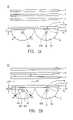
- FIG. 5Ais another analysis diagram of an optical path of the second embodiment of FIG. 3A ;
- FIG. 5Bis another analysis diagram of an optical path of the second embodiment of FIG. 3A ;
- FIG. 6is a cross-section view according to line (A—A) in FIG. 1 according to a third embodiment of the invention.
- a liquid crystal display Lcomprises a front frame L 1 , a panel L 2 , a backlight module M and a rear frame L 3 .
- the front frame L 1 and the rear frame L 3form a housing of the liquid crystal display L, wherein the panel L 2 and the backlight module M are enclosed by the front frame L 1 and the rear frame L 3 .
- the backlight module M of the inventionis a direct light type backlight module, providing a wavy reflector to replace a general flat-type reflector of a backlight module. Brightness of the backlight module M is thus increased and the light beams reflected by the wavy reflector are output in parallel, thus reducing interference and mura phenomenon between two adjacent light sources.
- a backlight module Mcomprises a base plate 1 providing two sidewalls 11 and 12 , a plurality of first reflectors 2 , a plurality of light sources 3 , a plurality of second reflectors 4 , a diffusive plate 5 and a diffusive film 6 .
- the diffusive plate 5 and the diffusive film 6are disposed next to the base plate 1 and facing the sidewall 12 of the base plate 1 .
- the base plate 1is made of transparent material, such as acryl resin; the first reflector 2 is wavy reflector, the light source 3 is a light tube, the second reflector 4 is a specular component made of trans-reflective material.
- the first reflector 2 and the light source 3are disposed on one side of the base plate 1 , i.e., the first reflector 2 and the light source 3 are facing the sidewall 11 of the base plate 1 , and the light source 3 is correspondingly disposed between the base plate 1 and the first reflectors 2 .
- the first reflector 2 disposed on the sidewall 11 of the base plate 1comprises a first reflecting surface 20 facing the base plate 1 .
- the first reflecting surface 20 of the first reflector 2is a parabolic and total-reflecting surface, and a first reference point a 1 and a second reference point a 2 are two different points randomly defined on the parabolic reflecting surface 20 of the first reflector 2 .
- the first reference point a 1 and the second reference point a 2have a common reference point 200 , i.e., the common reference point 200 is a focus of the reflecting surface 20 .
- the light source 3is disposed on the common reference point 200 , located between the base plate 1 and the first reflector 2 .
- the second reflector 4 disposed on the base plate 1provides a second reflecting surface 40 facing the light source 3 .
- the second reflecting surface 40 of the second reflector 4is a flat and total-reflecting surface, and a distance d exists between the second reflecting surface 40 of the second reflector 4 and the outer surface of the light source 3 .
- isolating the light sources 3 from each other by the acrylic base plate 1prevents rising-heat from the light sources 3 from damaging as the backlight module M is vertically disposed.
- a distance dpreferably of between 0 to 10 mm, is maintained.
- FIG. 2Btwo major paths taken by the light beam output from the light source 3 are depicted as following.
- One path of the light beam output from the light source 3is directly formed by the reflection of the first reflector 2 and passes through the base plate 1 toward the diffusive plate 5 .
- a first initial beam n 1 i and a second initial beam n 2 i from the light source 3are respectively reflected at the first and second reference points a 1 , a 2 of the reflecting surface 20 of the first reflector 2 to form a first reflecting light beam n 1 f and a second reflecting light beam n 2 f passing through the base plate 1 moving toward the diffusive plate 5 and the diffusive film 6 .
- the first and second reflecting light beams n 1 f , n 2 fare substantially parallel to each other when passing the base plate 1 .
- Another path of the light beam output from the light source 3is sequentially formed by the reflection of both the second reflector 4 and the first reflector 2 , passing through the base plate 1 toward the diffusive plate 5 .
- two light beams from the light source 3are also defined to be reflected at the first and second reference points a 1 , a 2 of the reflecting surface 20 of the first reflector 2 .
- Two reflecting light beams n 1 r , n 2 rreflected by the second reflecting surface 40 of the second reflector 4 according to two initial beams from the light source 3 , are respectively reflected at the first and second reference points a 1 , a 2 of the reflecting surface 20 of the first reflector 2 to form a first reflecting light beam n 1 f and a second reflecting light beam n 2 f to move toward the diffusive plate 5 and the diffusive film 6 .
- the first and second reflecting light beams n 1 f , n 2 fare substantially parallel to each other as passing the base plate 1 .
- the light beams (n 1 r , n 2 r ), from the light source 3 and reflected by the second reflecting surface 40 of the second reflector 4are reflected again by the reflecting surface 20 of the first reflector 2 , i.e., the light beams (n 1 r , n 2 r ) reflected by the second reflecting surface 40 of the second reflector 4 are reused to prevent mura phenomenon or interference on images projected from the backlight module M.
- the second reflecting surface 40 of the second reflector 4is preferably a flat and total-reflecting surface for increasing brightness and reflective rate.
- the second reflector 4is preferably made of a trans-reflective material capable of preventing mura phenomenon and interference.
- a backlight module M′ disposed on the base plate 1comprises a second reflector 4 ′.
- the second reflector 4 ′is a specular component having a second reflecting surface 40 ′ and a third reflecting surface 40 ′′.
- the second reflector 4 ′differs from the second reflector 4 in that the second reflecting surface 40 ′ and the third reflecting surface 40 ′′ are two parabolic total-reflecting surfaces, and the second reflecting surface 40 ′ faces the light source 3 and the third reflecting surface 40 ′′ is formed opposite to the second reflecting surface 40 ′, i.e., the second reflecting surface 40 ′ faces the diffusive plate 5 .
- a distance d′ measured from the second reflecting surface 40 of the second reflector 4 to the outer surface of the light source 3is between 0 to 10 mm.
- a first initial beam n 1 ′ i from the light source 3is reflected by the second reflecting surface 40 ′ to form a beam n 11 , and then the light beam n 11 is reflected by the first reflecting surface 20 at the point b 2 to form a first reflecting light beam n 1 ′ f .
- the first reflecting light beam n 1 ′fthen passes through the base plate 1 moves toward the diffusive plate 5 and the diffusive film 6 .
- the first reflecting light beam n 1 ′ f in FIG. 3Bis substantially parallel to the first and second reflecting light beams n 1 f , n 2 f in FIG. 2B .
- FIG. 4is an analysis diagram of anther optical path of the second embodiment of FIG. 3A .
- the second reflector 4 ′is made of trans-reflective material.
- a light beam s 1 itransmitted from the diffusive plate 5 , passes through the base plate 1 , the light beam s 1 i passes directly through the second reflector 4 ′ to form a light beam s 11 , and light beam s 11 is then reflected by the first reflecting surface 20 of the first reflector 2 at a point c to form a reflecting light beam s 1 f passing through the base plate 1 .
- the reflecting light beam s 1 f in FIG. 4is substantially parallel to the first and second reflecting light beams n 1 f , n 2 f in FIG. 2B .
- FIGS. 5A , 5 Bare analysis diagrams of two optical paths of light beams reflected by the third reflecting surface 40 ′′ of the second reflector 4 ′.
- a reference coordinate 400 ais a symmetrical plane passing the focus 400 of the parabolic reflecting surface 40 ′′ of the second reflector 4 ′, substantially perpendicular to the longitudinal direction of the base plate 1 .
- an incident angle “i”is the same as a reflection angle “r” with respect to the reference coordinate 400 a.
- FIG. 5Bas a light beam s 1 ′′ i transmitted from the diffusive plate 5 passes the focus 400 , the light beam s 1 ′′ i is reflected by the third reflecting surface 40 ′′ of the second reflector 4 ′ to form a reflecting light beam s 1 ′′ f , the propagation direction of the reflecting light beam s 1 ′′ f is substantially perpendicular to the longitudinal direction of the diffusive plate 5 , i.e., the reflecting light beam s 1 ′′ f is substantially parallel to the reflecting light beam s 1 f in FIG. 4 .
- the third reflecting surface 40 ′′ of the second reflector 4 ′reflects the light beams transmitted from the diffusive plate 5 , mura phenomenon or interference generated by the light sources 3 are reduced.
- a backlight module M′′comprises a base plate 1 ′′, a first reflector 2 ′′, a light source 3 ′′, at least two second reflectors 4 , a diffusive plate 5 and a diffusive film 6 .
- the first reflector 2 ′′comprises a first reflecting surface 20 ′′ facing the base plate 1 ′′.
- the backlight module M′′differs from the backlight module M in that the first reflecting surface 20 ′′ of the first reflectors 2 ′′ is a substantially U-shaped surface comprising a pair of asymmetrical, parabolic segments 20 a , 20 c and a flat segment 20 b disposed therebetween.
- the parabolic segment 20 aprovides a first reference point a 1 ′′ and a second reference point a 2 ′′, and the first reference point a 1 ′′ and the second reference point a 2 ′′ have a common reference point (focus) 200 a .
- the light source 3 ′′ disposed between the base plate 1 ′′ and the first reflector 2 ′′comprises at least two light tubes 31 , 32 , . . .
- the light tubes 31 and 3 nare respectively disposed on the focuses 200 a and 200 c of the parabolic segments 20 a and 20 c , and the light tubes 32 , . . . , 3 (n- 1 ) are lined up between the light tubes 31 and 3 n.
- the number of the light source 3 ′′ of the backlight module M′′can be larger than one, and each of which is individually and sequentially actuated. It is preferably that the second reflector 4 can also be replaced by the reflector 4 ′ of the backlight module M′ in the second embodiment.
Landscapes
- Physics & Mathematics (AREA)
- Nonlinear Science (AREA)
- Mathematical Physics (AREA)
- Chemical & Material Sciences (AREA)
- Crystallography & Structural Chemistry (AREA)
- General Physics & Mathematics (AREA)
- Optics & Photonics (AREA)
- Planar Illumination Modules (AREA)
- Liquid Crystal (AREA)
Abstract
Description
Claims (31)
Applications Claiming Priority (4)
| Application Number | Priority Date | Filing Date | Title |
|---|---|---|---|
| TW92127393 | 2003-10-03 | ||
| TW92127393ATWI283775B (en) | 2003-10-03 | 2003-10-03 | Liquid crystal display and backlight module thereof |
| TW93129303 | 2004-09-27 | ||
| TW093129303ATWI294542B (en) | 2003-10-03 | 2004-09-27 | Liquid crystal display and backlight module thereof |
Publications (2)
| Publication Number | Publication Date |
|---|---|
| US20050083674A1 US20050083674A1 (en) | 2005-04-21 |
| US7220044B2true US7220044B2 (en) | 2007-05-22 |
Family
ID=34525649
Family Applications (1)
| Application Number | Title | Priority Date | Filing Date |
|---|---|---|---|
| US10/953,258Expired - Fee RelatedUS7220044B2 (en) | 2003-10-03 | 2004-09-29 | Liquid crystal display and backlight module thereof |
Country Status (2)
| Country | Link |
|---|---|
| US (1) | US7220044B2 (en) |
| TW (1) | TWI294542B (en) |
Cited By (2)
| Publication number | Priority date | Publication date | Assignee | Title |
|---|---|---|---|---|
| US20080055930A1 (en)* | 2006-08-31 | 2008-03-06 | K-Bridge Electronics Co. , Ltd. | Backlight module |
| US11022840B2 (en) | 2017-03-03 | 2021-06-01 | Apple Inc. | Displays with direct-lit backlight units |
Families Citing this family (1)
| Publication number | Priority date | Publication date | Assignee | Title |
|---|---|---|---|---|
| WO2008098360A1 (en)* | 2007-02-16 | 2008-08-21 | Koninklijke Philips Electronics N.V. | Optical system for luminaire |
Citations (12)
| Publication number | Priority date | Publication date | Assignee | Title |
|---|---|---|---|---|
| US1050466A (en)* | 1909-06-15 | 1913-01-14 | Bassett Jones Jr | Reflector. |
| US4587601A (en)* | 1981-07-23 | 1986-05-06 | Collins Dynamics, Inc. | Combined flood and spot light incorporating a reflector member of circular and parabolic longitudinal cross section |
| US4755916A (en)* | 1981-07-23 | 1988-07-05 | Collins Dynamics | Combined flood and spot light |
| JP2001013880A (en) | 1999-06-30 | 2001-01-19 | Matsushita Electric Ind Co Ltd | Backlight device |
| US6290371B1 (en)* | 1999-01-23 | 2001-09-18 | Valeo Beleuchtung Deutschland Gmbh | Light for a vehicle |
| US6312144B1 (en)* | 2000-03-21 | 2001-11-06 | Cogent Light Technologies, Inc. | Optical system having retro-reflectors |
| TW463955U (en) | 2001-03-26 | 2001-11-11 | Prokia Technology Co Ltd | Light-collection module with high light-collection efficiency and the display device comprising this module |
| US6558032B2 (en)* | 2000-08-25 | 2003-05-06 | Stanley Electric Co., Ltd. | LED lighting equipment for vehicle |
| US6641293B2 (en)* | 2001-10-31 | 2003-11-04 | Visteon Global Technologies, Inc. | Light shield with reflective inner surface |
| US6758582B1 (en)* | 2003-03-19 | 2004-07-06 | Elumina Technology Incorporation | LED lighting device |
| US6893140B2 (en)* | 2002-12-13 | 2005-05-17 | W. T. Storey, Inc. | Flashlight |
| US7093955B2 (en)* | 2000-11-29 | 2006-08-22 | Zumtobel Staff Gmbh | Light with a transparent panel |
- 2004
- 2004-09-27TWTW093129303Apatent/TWI294542B/ennot_activeIP Right Cessation
- 2004-09-29USUS10/953,258patent/US7220044B2/ennot_activeExpired - Fee Related
Patent Citations (12)
| Publication number | Priority date | Publication date | Assignee | Title |
|---|---|---|---|---|
| US1050466A (en)* | 1909-06-15 | 1913-01-14 | Bassett Jones Jr | Reflector. |
| US4587601A (en)* | 1981-07-23 | 1986-05-06 | Collins Dynamics, Inc. | Combined flood and spot light incorporating a reflector member of circular and parabolic longitudinal cross section |
| US4755916A (en)* | 1981-07-23 | 1988-07-05 | Collins Dynamics | Combined flood and spot light |
| US6290371B1 (en)* | 1999-01-23 | 2001-09-18 | Valeo Beleuchtung Deutschland Gmbh | Light for a vehicle |
| JP2001013880A (en) | 1999-06-30 | 2001-01-19 | Matsushita Electric Ind Co Ltd | Backlight device |
| US6312144B1 (en)* | 2000-03-21 | 2001-11-06 | Cogent Light Technologies, Inc. | Optical system having retro-reflectors |
| US6558032B2 (en)* | 2000-08-25 | 2003-05-06 | Stanley Electric Co., Ltd. | LED lighting equipment for vehicle |
| US7093955B2 (en)* | 2000-11-29 | 2006-08-22 | Zumtobel Staff Gmbh | Light with a transparent panel |
| TW463955U (en) | 2001-03-26 | 2001-11-11 | Prokia Technology Co Ltd | Light-collection module with high light-collection efficiency and the display device comprising this module |
| US6641293B2 (en)* | 2001-10-31 | 2003-11-04 | Visteon Global Technologies, Inc. | Light shield with reflective inner surface |
| US6893140B2 (en)* | 2002-12-13 | 2005-05-17 | W. T. Storey, Inc. | Flashlight |
| US6758582B1 (en)* | 2003-03-19 | 2004-07-06 | Elumina Technology Incorporation | LED lighting device |
Cited By (2)
| Publication number | Priority date | Publication date | Assignee | Title |
|---|---|---|---|---|
| US20080055930A1 (en)* | 2006-08-31 | 2008-03-06 | K-Bridge Electronics Co. , Ltd. | Backlight module |
| US11022840B2 (en) | 2017-03-03 | 2021-06-01 | Apple Inc. | Displays with direct-lit backlight units |
Also Published As
| Publication number | Publication date |
|---|---|
| TWI294542B (en) | 2008-03-11 |
| US20050083674A1 (en) | 2005-04-21 |
| TW200611026A (en) | 2006-04-01 |
Similar Documents
| Publication | Publication Date | Title |
|---|---|---|
| JP5130434B2 (en) | Light guide plate and display device using the same | |
| JP4170343B2 (en) | Backlight module and its lens | |
| US20070046856A1 (en) | Liquid crystal display device | |
| CN110967787B (en) | Light guide plate and backlight module | |
| WO2018029892A1 (en) | Head-up display device and image display device therefor | |
| KR20080036182A (en) | Surface light source device | |
| CN113238315A (en) | Light source device and head-up display device | |
| US20130058126A1 (en) | Light-Source Unit, Back-Light Unit Having the Same, And Display Device Having the Same | |
| US20020109805A1 (en) | Backlight unit for liquid crystal display device and portable terminal equipment | |
| US9523886B2 (en) | Backlight unit having reflective/transmissive lens and display device having the same | |
| US7794100B2 (en) | Planar light source apparatus, display apparatus and planar illumination method | |
| JPH1196822A (en) | Surface illumination device and display device using the same | |
| JP6316494B1 (en) | Surface light source device and display device | |
| US20110019435A1 (en) | Brightness enhancement film and backlight module | |
| US20140241007A1 (en) | Reflector, light source module, and display device | |
| JPWO2011102033A1 (en) | Surface light source device and liquid crystal display device including the surface light source device | |
| KR20160083571A (en) | Super Directional Light Guide Film And Thin Film Type Back Light Unit For Flat Panel Display Using The Same | |
| US8313205B2 (en) | Lighting device for display device, display device and television receiver | |
| CN100580527C (en) | Multi-reflection device having multi-reflection structure, backlight unit and display device | |
| CN100401534C (en) | Light emitting diode element light emitting device, backlight module and light source adjusting method thereof | |
| KR20140066842A (en) | Backlight assembly and display device comprising the same | |
| US7220044B2 (en) | Liquid crystal display and backlight module thereof | |
| JP4580805B2 (en) | Light converging sheet, surface light source device, transmissive display device | |
| JP2001210129A (en) | Sidelight surface light source device | |
| TW201020635A (en) | Back light module and display device using the same |
Legal Events
| Date | Code | Title | Description |
|---|---|---|---|
| AS | Assignment | Owner name:CHI MEI OPTOELECTRONICS CORP., TAIWAN Free format text:ASSIGNMENT OF ASSIGNORS INTEREST;ASSIGNORS:HONG, HSIN-CHENG;HUANG, KUO-TSUN;REEL/FRAME:015849/0841 Effective date:20040205 | |
| STCF | Information on status: patent grant | Free format text:PATENTED CASE | |
| AS | Assignment | Owner name:CHIMEI INNOLUX CORPORATION,TAIWAN Free format text:MERGER;ASSIGNOR:CHI MEI OPTOELECTRONICS CORP.;REEL/FRAME:024358/0221 Effective date:20100318 Owner name:CHIMEI INNOLUX CORPORATION, TAIWAN Free format text:MERGER;ASSIGNOR:CHI MEI OPTOELECTRONICS CORP.;REEL/FRAME:024358/0221 Effective date:20100318 | |
| FPAY | Fee payment | Year of fee payment:4 | |
| AS | Assignment | Owner name:INNOLUX CORPORATION, TAIWAN Free format text:CHANGE OF NAME;ASSIGNOR:CHIMEI INNOLUX CORPORATION;REEL/FRAME:032604/0487 Effective date:20121219 | |
| FPAY | Fee payment | Year of fee payment:8 | |
| FEPP | Fee payment procedure | Free format text:MAINTENANCE FEE REMINDER MAILED (ORIGINAL EVENT CODE: REM.); ENTITY STATUS OF PATENT OWNER: LARGE ENTITY | |
| LAPS | Lapse for failure to pay maintenance fees | Free format text:PATENT EXPIRED FOR FAILURE TO PAY MAINTENANCE FEES (ORIGINAL EVENT CODE: EXP.); ENTITY STATUS OF PATENT OWNER: LARGE ENTITY | |
| STCH | Information on status: patent discontinuation | Free format text:PATENT EXPIRED DUE TO NONPAYMENT OF MAINTENANCE FEES UNDER 37 CFR 1.362 | |
| FP | Lapsed due to failure to pay maintenance fee | Effective date:20190522 |