US7219867B2 - Mount assembly for electronic devices - Google Patents
Mount assembly for electronic devicesDownload PDFInfo
- Publication number
- US7219867B2 US7219867B2US11/181,261US18126105AUS7219867B2US 7219867 B2US7219867 B2US 7219867B2US 18126105 AUS18126105 AUS 18126105AUS 7219867 B2US7219867 B2US 7219867B2
- Authority
- US
- United States
- Prior art keywords
- ball
- arms
- set forth
- assembly
- seat
- Prior art date
- Legal status (The legal status is an assumption and is not a legal conclusion. Google has not performed a legal analysis and makes no representation as to the accuracy of the status listed.)
- Expired - Lifetime, expires
Links
Images


Classifications
- F—MECHANICAL ENGINEERING; LIGHTING; HEATING; WEAPONS; BLASTING
- F16—ENGINEERING ELEMENTS AND UNITS; GENERAL MEASURES FOR PRODUCING AND MAINTAINING EFFECTIVE FUNCTIONING OF MACHINES OR INSTALLATIONS; THERMAL INSULATION IN GENERAL
- F16C—SHAFTS; FLEXIBLE SHAFTS; ELEMENTS OR CRANKSHAFT MECHANISMS; ROTARY BODIES OTHER THAN GEARING ELEMENTS; BEARINGS
- F16C11/00—Pivots; Pivotal connections
- F16C11/04—Pivotal connections
- F16C11/06—Ball-joints; Other joints having more than one degree of angular freedom, i.e. universal joints
- F16C11/0685—Manufacture of ball-joints and parts thereof, e.g. assembly of ball-joints
- F16C11/069—Manufacture of ball-joints and parts thereof, e.g. assembly of ball-joints with at least one separate part to retain the ball member in the socket; Quick-release systems
- B—PERFORMING OPERATIONS; TRANSPORTING
- B60—VEHICLES IN GENERAL
- B60R—VEHICLES, VEHICLE FITTINGS, OR VEHICLE PARTS, NOT OTHERWISE PROVIDED FOR
- B60R11/00—Arrangements for holding or mounting articles, not otherwise provided for
- B60R11/02—Arrangements for holding or mounting articles, not otherwise provided for for radio sets, television sets, telephones, or the like; Arrangement of controls thereof
- B60R11/0258—Arrangements for holding or mounting articles, not otherwise provided for for radio sets, television sets, telephones, or the like; Arrangement of controls thereof for navigation systems
- F—MECHANICAL ENGINEERING; LIGHTING; HEATING; WEAPONS; BLASTING
- F16—ENGINEERING ELEMENTS AND UNITS; GENERAL MEASURES FOR PRODUCING AND MAINTAINING EFFECTIVE FUNCTIONING OF MACHINES OR INSTALLATIONS; THERMAL INSULATION IN GENERAL
- F16C—SHAFTS; FLEXIBLE SHAFTS; ELEMENTS OR CRANKSHAFT MECHANISMS; ROTARY BODIES OTHER THAN GEARING ELEMENTS; BEARINGS
- F16C11/00—Pivots; Pivotal connections
- F16C11/04—Pivotal connections
- F16C11/06—Ball-joints; Other joints having more than one degree of angular freedom, i.e. universal joints
- F16C11/0619—Ball-joints; Other joints having more than one degree of angular freedom, i.e. universal joints the female part comprising a blind socket receiving the male part
- F16C11/0623—Construction or details of the socket member
- F16C11/0657—Construction or details of the socket member the socket member being mainly made of plastics
- F—MECHANICAL ENGINEERING; LIGHTING; HEATING; WEAPONS; BLASTING
- F16—ENGINEERING ELEMENTS AND UNITS; GENERAL MEASURES FOR PRODUCING AND MAINTAINING EFFECTIVE FUNCTIONING OF MACHINES OR INSTALLATIONS; THERMAL INSULATION IN GENERAL
- F16M—FRAMES, CASINGS OR BEDS OF ENGINES, MACHINES OR APPARATUS, NOT SPECIFIC TO ENGINES, MACHINES OR APPARATUS PROVIDED FOR ELSEWHERE; STANDS; SUPPORTS
- F16M11/00—Stands or trestles as supports for apparatus or articles placed thereon ; Stands for scientific apparatus such as gravitational force meters
- F16M11/02—Heads
- F16M11/04—Means for attachment of apparatus; Means allowing adjustment of the apparatus relatively to the stand
- F16M11/06—Means for attachment of apparatus; Means allowing adjustment of the apparatus relatively to the stand allowing pivoting
- F16M11/12—Means for attachment of apparatus; Means allowing adjustment of the apparatus relatively to the stand allowing pivoting in more than one direction
- F16M11/14—Means for attachment of apparatus; Means allowing adjustment of the apparatus relatively to the stand allowing pivoting in more than one direction with ball-joint
- F—MECHANICAL ENGINEERING; LIGHTING; HEATING; WEAPONS; BLASTING
- F16—ENGINEERING ELEMENTS AND UNITS; GENERAL MEASURES FOR PRODUCING AND MAINTAINING EFFECTIVE FUNCTIONING OF MACHINES OR INSTALLATIONS; THERMAL INSULATION IN GENERAL
- F16M—FRAMES, CASINGS OR BEDS OF ENGINES, MACHINES OR APPARATUS, NOT SPECIFIC TO ENGINES, MACHINES OR APPARATUS PROVIDED FOR ELSEWHERE; STANDS; SUPPORTS
- F16M13/00—Other supports for positioning apparatus or articles; Means for steadying hand-held apparatus or articles
- F16M13/02—Other supports for positioning apparatus or articles; Means for steadying hand-held apparatus or articles for supporting on, or attaching to, an object, e.g. tree, gate, window-frame, cycle
- F16M13/022—Other supports for positioning apparatus or articles; Means for steadying hand-held apparatus or articles for supporting on, or attaching to, an object, e.g. tree, gate, window-frame, cycle repositionable
- B—PERFORMING OPERATIONS; TRANSPORTING
- B60—VEHICLES IN GENERAL
- B60R—VEHICLES, VEHICLE FITTINGS, OR VEHICLE PARTS, NOT OTHERWISE PROVIDED FOR
- B60R11/00—Arrangements for holding or mounting articles, not otherwise provided for
- B60R2011/0001—Arrangements for holding or mounting articles, not otherwise provided for characterised by position
- B60R2011/0003—Arrangements for holding or mounting articles, not otherwise provided for characterised by position inside the vehicle
- B60R2011/0026—Windows, e.g. windscreen
- B—PERFORMING OPERATIONS; TRANSPORTING
- B60—VEHICLES IN GENERAL
- B60R—VEHICLES, VEHICLE FITTINGS, OR VEHICLE PARTS, NOT OTHERWISE PROVIDED FOR
- B60R11/00—Arrangements for holding or mounting articles, not otherwise provided for
- B60R2011/0042—Arrangements for holding or mounting articles, not otherwise provided for characterised by mounting means
- B60R2011/0049—Arrangements for holding or mounting articles, not otherwise provided for characterised by mounting means for non integrated articles
- B60R2011/005—Connection with the vehicle part
- B60R2011/0056—Connection with the vehicle part using suction cups
- B—PERFORMING OPERATIONS; TRANSPORTING
- B60—VEHICLES IN GENERAL
- B60R—VEHICLES, VEHICLE FITTINGS, OR VEHICLE PARTS, NOT OTHERWISE PROVIDED FOR
- B60R11/00—Arrangements for holding or mounting articles, not otherwise provided for
- B60R2011/0042—Arrangements for holding or mounting articles, not otherwise provided for characterised by mounting means
- B60R2011/008—Adjustable or movable supports
- B60R2011/0085—Adjustable or movable supports with adjustment by rotation in their operational position
- B60R2011/0089—Adjustable or movable supports with adjustment by rotation in their operational position around three axes, i.e. universally mounted
- Y—GENERAL TAGGING OF NEW TECHNOLOGICAL DEVELOPMENTS; GENERAL TAGGING OF CROSS-SECTIONAL TECHNOLOGIES SPANNING OVER SEVERAL SECTIONS OF THE IPC; TECHNICAL SUBJECTS COVERED BY FORMER USPC CROSS-REFERENCE ART COLLECTIONS [XRACs] AND DIGESTS
- Y10—TECHNICAL SUBJECTS COVERED BY FORMER USPC
- Y10T—TECHNICAL SUBJECTS COVERED BY FORMER US CLASSIFICATION
- Y10T403/00—Joints and connections
- Y10T403/32—Articulated members
- Y10T403/32606—Pivoted
- Y10T403/32631—Universal ball and socket
- Y10T403/32721—Elastomeric seat
- Y—GENERAL TAGGING OF NEW TECHNOLOGICAL DEVELOPMENTS; GENERAL TAGGING OF CROSS-SECTIONAL TECHNOLOGIES SPANNING OVER SEVERAL SECTIONS OF THE IPC; TECHNICAL SUBJECTS COVERED BY FORMER USPC CROSS-REFERENCE ART COLLECTIONS [XRACs] AND DIGESTS
- Y10—TECHNICAL SUBJECTS COVERED BY FORMER USPC
- Y10T—TECHNICAL SUBJECTS COVERED BY FORMER US CLASSIFICATION
- Y10T403/00—Joints and connections
- Y10T403/32—Articulated members
- Y10T403/32606—Pivoted
- Y10T403/32631—Universal ball and socket
- Y10T403/32737—Universal ball and socket including liner, shim, or discrete seat
Definitions
- the present inventionrelates to the field of mounting assemblies for electronic devices. More particularly, the invention relates to a mounting assembly with a ball and socket joint, wherein the ball and socket are easily separable for quick installation and removal of an electronic device.
- One type of mounting apparatus used with portable electronic devicesincludes a base connected to a cradle via a ball and socket joint.
- the baseis fixedly or permanently secured to a surface of the vehicle, and the ball and socket joint allows the cradle to be selectively positioned in any of a broad range of positions relative to the base.
- the cradlereceives an electronic device and retains the electronic device with screws or similar fastening devices, allowing a user to selectively adjust a position or orientation of the electronic device.
- the present inventionsolves the above-described problems and provides a distinct advance in the art of vehicle mounting assemblies for electronic devices. More particularly, the present invention involves a mounting assembly with a separable ball and socket joint that eliminates the need for a cradle interposed between a mount and an electronic device.
- the inventioncomprises a mount that may be secured to a surface of a vehicle, a mounting ball projecting from the mount, and a housing for encasing an electronic device.
- the housingincludes a socket assembly for receiving and frictionally engaging the ball to retain the housing in a fixed position relative to the mount.
- the socket assemblycomprises an orifice formed in the back of the housing, a seat positioned in the orifice for matingly receiving the ball, and a spring element partially surrounding the seat.
- the seatincludes a concave portion and flexible, interconnected arms extending from the concave portion for contacting an outer surface of the ball and frictionally resisting rotation of the ball relative to the orifice.
- the spring elementsubstantially encircles the flexible arms to allow the flexible arms to flex outward when receiving the ball and to then contract inwardly to firmly hold the ball when the ball is seated fully in the seat.
- a third embodiment of the inventioninvolves an assembly for removably mounting an electronic device to a vehicle.
- the assemblycomprises a suction-cup mount removably attachable to a surface of the vehicle, a mounting ball projecting from the mount, an electronic device with a housing for encasing the electronic device, and a socket assembly integrally formed in the housing.
- the socket assemblyincludes an orifice formed in the back of the housing, a seat positioned in the orifice for matingly receiving the ball, and a spring element partially surrounding the seat.
- the seatfurther includes a concave center portion and a plurality of flexible, interconnected arms extending from the concave portion.
- the armsform a cage smaller in diameter than the ball when the arms are in a relaxed state and are curved to substantially conform to the outer surface of the ball and to engage a hemisphere of the ball distal the concave center portion to retain the ball in the seat.
- the spring elementincludes a metal spring ring substantially encircling the arms, wherein the spring ring allows the arms to flex outward when receiving and releasing the ball, and to contract inwardly to contact the ball when the ball is seated fully in the seat.
- FIG. 1is a perspective view of a mounting assembly for a portable electronic device constructed according to a preferred embodiment of the invention
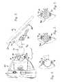
- FIG. 2is an exploded rear perspective view of the mounting assembly of FIG. 1 , illustrating a ball and socket joint that separably secures an electronic device to a mount;
- FIG. 3is a side elevation view of the mounting assembly of FIG. 1 , wherein the ball is illustrated separated from the socket;
- FIG. 4is a fragmentary view of the ball and socket of the mounting assembly of FIG. 1 , wherein the ball is snapped into the socket;
- FIG. 5is a fragmentary view of the ball and socket of the mounting assembly of FIG. 1 taken along line 5 - 5 of FIG. 2 , wherein the ball is snapped into the socket;
- FIG. 6is a fragmentary view of the ball and socket of the mounting assembly of FIG. 1 , wherein a plurality of plastic arms of the socket are flexed outward to allow the ball to pass into the socket.
- the mounting assembly 10comprises a mount 12 including a base 14 and a mounting ball 16 ; and a housing 18 for a portable electronic device 20 , wherein the housing 18 presents a socket assembly 22 for receiving the ball 16 .
- the mount 12removably secures to a surface of a vehicle (see FIG. 3 ), such as a windshield of the vehicle, and supports the electronic device 20 in view of a user, such as a vehicle driver or passenger.
- the mount 12includes a rigid circular base 14 that is generally convex so as to curve away from the vehicle surface.
- a flexible sheet 24is positioned between the base 14 and the vehicle surface for engaging the vehicle surface with a vacuum grip, wherein an air-tight seal is created between the flexible sheet 24 and the vehicle surface.
- the mount 12can also be replaced with a mount that is more permanently applied to the windshield or other surface with adhesives, a mount with a weighted base that rests on a vehicle dashboard, or any other type of mounting device.
- a lever 26is positioned generally in a center of the base 14 and connects to a center of the flexible sheet 24 through the base 14 and enables the user to actuate the flexible sheet 24 to create the vacuum gripping function.
- a tab 28 of the flexible sheet 24extends beyond a rim of the base 14 and enables a user to release the mount 12 by breaking the air-tight seal between the flexible sheet 24 and the vehicle surface.
- the vacuum grip or “suction cup” function of the mount 12is substantially conventional in nature and therefore will not be described in greater detail here.
- the ball 16is connected to the base 14 via a neck 30 projecting from the base 14 .
- the neck 30is eccentrically located on the base 14 and projects substantially normally therefrom, but projects slightly away from a center of the base 14 .
- the ball 16is connected to the neck 30 such that a center of the ball 16 is proximate a line extending normally from an edge of the base 14 and is spaced approximately one and one-quarter inches from the base 14 .
- the ball 16is substantially rigid to prevent deformation thereof and presents an outer surface that introduces sufficient friction between the ball 16 and the socket assembly 22 to resist movement of the electronic device 20 relative to the mount 12 .
- the ball 16is thus constructed of plastic or another sturdy material that presents a rough surface, or is coated to present a rough or soft surface with the friction characteristics described above.
- the electronic device 20may be any portable electronic device to be removably mounted in a vehicle.
- the illustrated device 20is a model i3 STREETPILOTTM GPS-based navigational device manufactured by GARMINTM.
- the housing 18 of the electronic device 20encases the electronic device 20 and is substantially conventional, except that the housing 18 presents a socket assembly 22 for removably connecting directly to the ball 16 of the mount 12 , wherein the socket assembly 22 frictionally engages the ball 16 to retain the housing 18 in a fixed position relative to the mount 12 .
- the socket assembly 22generally comprises an orifice 32 formed in the back of the housing 18 , a seat 34 positioned in the orifice 32 for matingly receiving the ball 16 , and a spring element 36 partially surrounding the seat 34 .
- the seatincludes a concave center portion 38 and a plurality of flexible, interconnected arms.
- four arms 40 , 42 , 44are spaced at 90° intervals and extend from the concave center portion.
- the concave center portion 38presents a continuous, bowl-shaped surface concave to the orifice 32 such that the center portion 38 matingly receives the ball 16 .
- the center portion 38is constructed of plastic or other material presenting a surface that introduces friction between the center portion 38 and the ball 16 to resist movement of the ball 16 relative to the orifice 32 .
- the center portion 38is in a fixed position relative to the housing 18 and is substantially rigid so as not to yield to pressure exerted by the ball 16 .
- the arms 40 , 42 , 44are connected to and extend from a periphery of the center portion 38 and are curved to form a circular cage, wherein the center portion 38 and the arms 40 , 42 , 44 together define a generally spherical cavity for receiving and retaining the ball 16 .
- the ball 16 and seat 34are constructed such that the ball 16 snaps into and out of the spherical cavity defined by the seat 34 .
- the inside of the cage formed by the arms 40 , 42 , 44is slightly smaller in diameter than an external surface of the ball 16 , such that when the ball 16 is inserted into the cage the arms 40 , 42 , 44 engage and press against the ball 16 .
- FIGS. 4-5illustrated the arms 40 , 42 , 44 engaging the ball 16 when the ball 16 is seated in the socket assembly 22 .
- the arms 40 , 42 , 44curve around the ball 16 from the periphery of the center portion 38 to a point that is on a hemisphere of the ball 16 opposite the center portion 38 to retain the ball 16 in the seat 32 .
- the arms 40 , 42 , 44“reach around” the ball 16 from the center portion 38 such that the opening of the cage is smaller than the diameter of the ball 16 .
- FIG. 6illustrates the arms 40 , 42 , 44 flexing outward to accommodate passage of the ball 16 .
- the spring element 36partially encircles the arms 40 , 42 , 44 and is operable to bias the arms 40 , 42 , 44 inwardly to contact the ball 16 when the ball 16 is in the socket assembly 22 , while allowing the arms 40 , 42 , 44 to flex outwardly to receive and release the ball 16 .
- the illustrated spring element 36is a metal spring ring that substantially encircles the arms 40 , 42 , 44 , and is approximately one-quarter to one-half of an inch wide, approximately three-quarters of an inch in diameter, and presents a gap 46 of approximately one-eighth to one-quarter inch between ends. thereof. The gap 46 allows the spring ring to flex.
- the spring element 36When the ball 16 is not in the socket assembly 22 , the spring element 36 is relaxed and applies little or no biasing pressure on the arms 40 , 42 , 44 .
- the arms 40 , 42 , 44flex outwardly, as discussed above, and engage the spring element 36 , causing the spring element 36 to also flex outwardly wherein the gap 46 widens.
- the spring element 36biases the arms 40 , 42 , 44 inwardly against the ball 16 .
- the arms 40 , 42 , 44 and the spring element 36cooperate to frictionally resist rotation of the ball 16 within the socket assembly 22 and to retain the ball 16 in the socket assembly 22 .
- the cooperation between the arms 40 , 42 , 44 and spring element 36presents a distinct advance in the art because, among other things, the combination is more effective in retaining the ball 16 within the socket assembly 22 than either component would be individually.
- the spring element 36 acting alonewould provide less contact area with the ball 16 , and metal would provide less friction against the ball 16 to resist rotation of the ball 16 within the socket assembly 22 .
- the mount 12is installed in a vehicle by selecting a suitably smooth and flat surface. Such a surface may be on a windshield, other window, or dashboard. Alternatively, a specially made material may be attached to a surface of the vehicle to provide a superior mounting surface for the suction cup mount.
- the mount 12is pressed onto the surface and the lever 26 is flipped downward to secure the mount 12 to the surface via the vacuum grip function. Once the mount 12 is secured to the surface, the electronic device 20 may be easily snapped onto and off of the mount 12 .
- the usersimply places the orifice 32 of the socket assembly 22 over the ball 16 and pushes the socket assembly 22 onto the ball 16 .
- the electronic device 20may then be repositioned as the user desires and the arms 40 , 42 , 44 will cause the electronic device 20 to remain in its current position.
- the electronic device 20is rotated to an extreme angle relative to the mount 12 , such as to the user's left or right, and then pushed beyond the angle to cause the socket assembly 22 to snap off of the ball 16 .
- the electronic device 20can be pulled straight out to cause the socket assembly to snap off the ball, but this requires more pulling force.
- the mount 12is removed from the vehicle's surface by lifting the lever 26 away from the base 14 of the mount 12 to release the suction cup and the tab is pulled away from the vehicle surface.
- the metal spring ring 40may be replaced with a similar element capable of biasing the arms 40 , 42 , 44 against the ball 16 including, for example, a plastic spring ring or a rubber or elastomer ring that entirely encircles the arms 40 , 42 , 44 .
- the arms 40 , 42 , 44need not be plastic buy may be constructed of any flexible, friction-producing material and may be connected to an element of the housing 18 other than the center portion 38 .
- use of the ball and socket assembly disclosed hereinis not restricted to portable electronic devices, but may also be used to removably retain other devices, such as, for example, mirrors.
Landscapes
- Engineering & Computer Science (AREA)
- General Engineering & Computer Science (AREA)
- Mechanical Engineering (AREA)
- Radar, Positioning & Navigation (AREA)
- Remote Sensing (AREA)
- Casings For Electric Apparatus (AREA)
- Hooks, Suction Cups, And Attachment By Adhesive Means (AREA)
- Fittings On The Vehicle Exterior For Carrying Loads, And Devices For Holding Or Mounting Articles (AREA)
- Coupling Device And Connection With Printed Circuit (AREA)
- Pivots And Pivotal Connections (AREA)
- Piezo-Electric Or Mechanical Vibrators, Or Delay Or Filter Circuits (AREA)
- Mounting Components In General For Electric Apparatus (AREA)
Abstract
Description
1. Field of the Invention
The present invention relates to the field of mounting assemblies for electronic devices. More particularly, the invention relates to a mounting assembly with a ball and socket joint, wherein the ball and socket are easily separable for quick installation and removal of an electronic device.
2. Description of the Prior Art
The use of electronic devices in vehicles has increased in recent years. For example, it is increasingly more common to see electronic devices such as global positioning satellite (GPS) devices, portable telephones, radios and personal digital assistants (PDAs) mounted within vehicles either permanently or, in the case of portable electronics, removably. Many of these devices have displays which visibly communicate information to one or more users. Thus, it is advantageous to be able to adjust a position and angle of such devices to provide maximum viewing capability to the user or users. Portable devices are further advantageous in that they can be taken from the vehicle and used outside of the vehicle.
Due to the wide variety of electronic devices that can be mounted within a vehicle, many different types of mounting apparatuses exist that can secure an electronic device to the dashboard, windshield, floor, or other support surface in a vehicle such that a user may adjust a position of the device. One type of mounting apparatus used with portable electronic devices includes a base connected to a cradle via a ball and socket joint. The base is fixedly or permanently secured to a surface of the vehicle, and the ball and socket joint allows the cradle to be selectively positioned in any of a broad range of positions relative to the base. The cradle receives an electronic device and retains the electronic device with screws or similar fastening devices, allowing a user to selectively adjust a position or orientation of the electronic device.
While this type of prior art mounting apparatus is operable to mount a portable electronic device to a vehicle so that the device can be repositioned, it suffers from certain limitations. The cradles of prior mount apparatuses increase the size, weight, and cost of the apparatus, for example, and require a user to loosen or tighten the screws or other fasteners each time the electronic devices are mounted to or removed from the cradles, and loosen and subsequently tighten the screws each time it is desired to re-position the electronic devices.
Accordingly, there is a need for an improved vehicle mounting apparatus for a portable electronic device that does not suffer from the problems and limitations of the prior art.
The present invention solves the above-described problems and provides a distinct advance in the art of vehicle mounting assemblies for electronic devices. More particularly, the present invention involves a mounting assembly with a separable ball and socket joint that eliminates the need for a cradle interposed between a mount and an electronic device.
According to a first embodiment, the invention comprises a mount that may be secured to a surface of a vehicle, a mounting ball projecting from the mount, and a housing for encasing an electronic device. The housing includes a socket assembly for receiving and frictionally engaging the ball to retain the housing in a fixed position relative to the mount.
According to a second embodiment of the invention, the socket assembly comprises an orifice formed in the back of the housing, a seat positioned in the orifice for matingly receiving the ball, and a spring element partially surrounding the seat. The seat includes a concave portion and flexible, interconnected arms extending from the concave portion for contacting an outer surface of the ball and frictionally resisting rotation of the ball relative to the orifice. The spring element substantially encircles the flexible arms to allow the flexible arms to flex outward when receiving the ball and to then contract inwardly to firmly hold the ball when the ball is seated fully in the seat.
A third embodiment of the invention involves an assembly for removably mounting an electronic device to a vehicle. The assembly comprises a suction-cup mount removably attachable to a surface of the vehicle, a mounting ball projecting from the mount, an electronic device with a housing for encasing the electronic device, and a socket assembly integrally formed in the housing. The socket assembly includes an orifice formed in the back of the housing, a seat positioned in the orifice for matingly receiving the ball, and a spring element partially surrounding the seat. The seat further includes a concave center portion and a plurality of flexible, interconnected arms extending from the concave portion. The arms form a cage smaller in diameter than the ball when the arms are in a relaxed state and are curved to substantially conform to the outer surface of the ball and to engage a hemisphere of the ball distal the concave center portion to retain the ball in the seat. The spring element includes a metal spring ring substantially encircling the arms, wherein the spring ring allows the arms to flex outward when receiving and releasing the ball, and to contract inwardly to contact the ball when the ball is seated fully in the seat.
These and other important aspects of the present invention are described more fully in the detailed description below.
A preferred embodiment of the present invention is described in detail below with reference to the attached drawing figures, wherein:
Referring initially toFIGS. 1 and 2 , an exemplary mounting assembly for electronic devices employing the principles of the present invention is shown and designated generally by thereference numeral 10. Themounting assembly 10 comprises amount 12 including abase 14 and amounting ball 16; and ahousing 18 for a portableelectronic device 20, wherein thehousing 18 presents asocket assembly 22 for receiving theball 16.
Themount 12 removably secures to a surface of a vehicle (seeFIG. 3 ), such as a windshield of the vehicle, and supports theelectronic device 20 in view of a user, such as a vehicle driver or passenger. Themount 12 includes a rigidcircular base 14 that is generally convex so as to curve away from the vehicle surface. Aflexible sheet 24 is positioned between thebase 14 and the vehicle surface for engaging the vehicle surface with a vacuum grip, wherein an air-tight seal is created between theflexible sheet 24 and the vehicle surface. Themount 12 can also be replaced with a mount that is more permanently applied to the windshield or other surface with adhesives, a mount with a weighted base that rests on a vehicle dashboard, or any other type of mounting device.
Alever 26 is positioned generally in a center of thebase 14 and connects to a center of theflexible sheet 24 through thebase 14 and enables the user to actuate theflexible sheet 24 to create the vacuum gripping function. Atab 28 of theflexible sheet 24 extends beyond a rim of thebase 14 and enables a user to release themount 12 by breaking the air-tight seal between theflexible sheet 24 and the vehicle surface. The vacuum grip or “suction cup” function of themount 12 is substantially conventional in nature and therefore will not be described in greater detail here.
Referring also toFIG. 3 , theball 16 is connected to thebase 14 via aneck 30 projecting from thebase 14. Theneck 30 is eccentrically located on thebase 14 and projects substantially normally therefrom, but projects slightly away from a center of thebase 14. Theball 16 is connected to theneck 30 such that a center of theball 16 is proximate a line extending normally from an edge of thebase 14 and is spaced approximately one and one-quarter inches from thebase 14. Theball 16 is substantially rigid to prevent deformation thereof and presents an outer surface that introduces sufficient friction between theball 16 and thesocket assembly 22 to resist movement of theelectronic device 20 relative to themount 12. Theball 16 is thus constructed of plastic or another sturdy material that presents a rough surface, or is coated to present a rough or soft surface with the friction characteristics described above.
Theelectronic device 20 may be any portable electronic device to be removably mounted in a vehicle. The illustrateddevice 20 is a model i3 STREETPILOT™ GPS-based navigational device manufactured by GARMIN™. Thehousing 18 of theelectronic device 20 encases theelectronic device 20 and is substantially conventional, except that thehousing 18 presents asocket assembly 22 for removably connecting directly to theball 16 of themount 12, wherein thesocket assembly 22 frictionally engages theball 16 to retain thehousing 18 in a fixed position relative to themount 12. Thesocket assembly 22 generally comprises anorifice 32 formed in the back of thehousing 18, aseat 34 positioned in theorifice 32 for matingly receiving theball 16, and aspring element 36 partially surrounding theseat 34.
The seat includes aconcave center portion 38 and a plurality of flexible, interconnected arms. In one embodiment, fourarms 40,42,44 (only three of which are visible in the drawing figures) are spaced at 90° intervals and extend from the concave center portion. However, any number of arms may be provided without departing from the scope of the present invention. Theconcave center portion 38 presents a continuous, bowl-shaped surface concave to theorifice 32 such that thecenter portion 38 matingly receives theball 16. Thecenter portion 38 is constructed of plastic or other material presenting a surface that introduces friction between thecenter portion 38 and theball 16 to resist movement of theball 16 relative to theorifice 32. Furthermore, thecenter portion 38 is in a fixed position relative to thehousing 18 and is substantially rigid so as not to yield to pressure exerted by theball 16.
Thearms center portion 38 and are curved to form a circular cage, wherein thecenter portion 38 and thearms ball 16. Theball 16 andseat 34 are constructed such that theball 16 snaps into and out of the spherical cavity defined by theseat 34. When thearms arms ball 16, such that when theball 16 is inserted into the cage thearms ball 16. In this manner, thearms ball 16 within thesocket assembly 22 and require a user to manually push theelectronic device 20 from a first position to a second position relative to themount 12.FIGS. 4-5 illustrated thearms ball 16 when theball 16 is seated in thesocket assembly 22.
Thearms ball 16 from the periphery of thecenter portion 38 to a point that is on a hemisphere of theball 16 opposite thecenter portion 38 to retain theball 16 in theseat 32. In other words, thearms ball 16 from thecenter portion 38 such that the opening of the cage is smaller than the diameter of theball 16. This allows theball 16 to be snapped into thesocket assembly 22 by forcing theball 16 into thesocket assembly 22 and toward thecenter portion 38 of theseat 32, wherein thearms ball 16 to pass through the opening of the cage and then contract inward when theball 16 is fully seated in thesocket assembly 22. Likewise, thearms ball 16 by flexing outward when theball 16 is forced away from thecenter portion 38 of theseat 34 and out of thesocket assembly 22.FIG. 6 illustrates thearms ball 16.
Thespring element 36 partially encircles thearms arms ball 16 when theball 16 is in thesocket assembly 22, while allowing thearms ball 16. The illustratedspring element 36 is a metal spring ring that substantially encircles thearms ball 16 is not in thesocket assembly 22, thespring element 36 is relaxed and applies little or no biasing pressure on thearms ball 16 is forced into thesocket assembly 22, thearms spring element 36, causing thespring element 36 to also flex outwardly wherein the gap46 widens. When theball 16 is snapped into the seated position thespring element 36 biases thearms ball 16.
Thus, thearms spring element 36 cooperate to frictionally resist rotation of theball 16 within thesocket assembly 22 and to retain theball 16 in thesocket assembly 22. The cooperation between thearms spring element 36 presents a distinct advance in the art because, among other things, the combination is more effective in retaining theball 16 within thesocket assembly 22 than either component would be individually. Thearms arms spring element 36, and may permanently bend outward or even break after repeated use. Furthermore, thespring element 36 acting alone would provide less contact area with theball 16, and metal would provide less friction against theball 16 to resist rotation of theball 16 within thesocket assembly 22.
In use, themount 12 is installed in a vehicle by selecting a suitably smooth and flat surface. Such a surface may be on a windshield, other window, or dashboard. Alternatively, a specially made material may be attached to a surface of the vehicle to provide a superior mounting surface for the suction cup mount. Themount 12 is pressed onto the surface and thelever 26 is flipped downward to secure themount 12 to the surface via the vacuum grip function. Once themount 12 is secured to the surface, theelectronic device 20 may be easily snapped onto and off of themount 12.
To secure theelectronic device 20 to themount 12, the user simply places theorifice 32 of thesocket assembly 22 over theball 16 and pushes thesocket assembly 22 onto theball 16. Theelectronic device 20 may then be repositioned as the user desires and thearms electronic device 20 to remain in its current position. To remove theelectronic device 20 from themount 12, theelectronic device 20 is rotated to an extreme angle relative to themount 12, such as to the user's left or right, and then pushed beyond the angle to cause thesocket assembly 22 to snap off of theball 16. Alternatively, theelectronic device 20 can be pulled straight out to cause the socket assembly to snap off the ball, but this requires more pulling force. Themount 12 is removed from the vehicle's surface by lifting thelever 26 away from thebase 14 of themount 12 to release the suction cup and the tab is pulled away from the vehicle surface.
Although the invention has been described with reference to a particular embodiment illustrated in the attached drawings, it is noted that equivalents may be employed and substitutions made herein without departing from the scope of the invention as recited in the claims. It will be appreciated, for example, that themetal spring ring 40 may be replaced with a similar element capable of biasing thearms ball 16 including, for example, a plastic spring ring or a rubber or elastomer ring that entirely encircles thearms arms housing 18 other than thecenter portion 38. Further yet, it will be appreciated that use of the ball and socket assembly disclosed herein is not restricted to portable electronic devices, but may also be used to removably retain other devices, such as, for example, mirrors.
Claims (29)
1. A navigational device comprising:
a mount for being secured to a surface of a vehicle and presenting a mounting ball; and
a housing for encasing the navigational device, wherein the housing includes a socket assembly for receiving and frictionally engaging the ball to moveably attach the housing to the mount, wherein the socket assembly includes a seat formed of a flexible, friction-producing material biased against the ball, wherein sufficient friction exists between the friction-producing material and the ball to prevent the housing from moving relative to the mount in the absence of user-applied force.
2. The navigational device as set forth inclaim 1 , wherein the mount is a suction cup mount.
3. The navigational device as set forth inclaim 1 , wherein the friction-producing material includes a plastic element.
4. The navigational device as set forth inclaim 1 , wherein the seat includes a plurality of arms that form a cage substantially surrounding the ball.
5. The navigational device as set forth inclaim 4 , wherein the seat further includes a concave center portion, wherein the arms extend from a periphery of the center portion.
6. The navigational device as set forth inclaim 5 , wherein the arms are formed integrally with the center portion and extend from a periphery of the center portion.
7. The navigational device as set forth inclaim 4 , wherein the arms are curved to substantially conform to an outer surface of the ball and to engage a hemisphere of the ball distal the seat to retain the ball in the seat.
8. The navigational device as set forth inclaim 1 , wherein the friction-producing material is biased against the ball by a spring element.
9. The navigational device as set forth inclaim 8 , wherein the spring element includes a circular spring element that partially encircles the friction-producing material.
10. The navigational device as set forth inclaim 9 , wherein the circular spring element is a metal spring ring that substantially encircles the friction-producing material.
11. An assembly for removably mounting an electronic device to a vehicle, the assembly comprising:
a suction-cup mount removably attachable to a surface of the vehicle;
a mounting ball projecting from the mount;
an electronic device with a housing for encasing the electronic device;
an orifice in a back of the electronic device,
a seat positioned in the orifice for matingly receiving the ball, the seat including—
a concave center portion for receiving the ball, and
a plurality of arms extending from a periphery of the center portion for contacting an outer surface of the ball and frictionally resisting rotation of the ball relative to the orifice, wherein the arms form a cage smaller in diameter than the ball when the arms are in a relaxed state, and wherein the arms are curved to substantially conform to the outer surface of the ball and to engage a hemisphere of the ball distal the center portion to retain the ball in the seat; and
a metal spring ring substantially encircling the arms, wherein the spring ring allows the arms to flex outward to receive and to release the ball and biases the arms inwardly to contact the ball when the ball is fully seated in the seat.
12. A ball and socket assembly comprising:
a ball;
a seat for matingly receiving the ball, the seat including—
a concave center portion, and
a plurality of interconnected arms extending from the concave center portion for contacting an outer surface of the ball and frictionally resisting rotation of the ball relative to the seat; and
a spring element substantially encircling the arms, wherein the spring element allows the arms to flex outward to receive the ball and biases the arms inwardly to contact the ball when the ball is seated in the concave seat.
13. The assembly as set forth inclaim 12 , wherein the arms are formed of flexible material.
14. The assembly as set forth inclaim 13 , wherein the arms form a cage smaller in diameter than the ball when the arms are in a relaxed state.
15. The assembly as set forth inclaim 14 , wherein the arms are curved to substantially conform to the outer surface of the ball and to engage a hemisphere of the ball distal the concave center portion to retain the ball in the seat.
16. The assembly as set forth inclaim 15 , wherein the concave center portion is made of plastic and is integrally formed with the arms.
17. The assembly as set forth inclaim 16 , wherein the arms extend from a periphery of the concave center portion such that the concave center portion and the arms define a substantially spherical cavity.
18. The assembly as set forth inclaim 12 , wherein the spring element is a metal spring ring that substantially encircles the flexible material.
19. The assembly as set forth inclaim 12 , wherein the spring element is a plastic spring ring that substantially encircles the flexible material.
20. An assembly comprising:
an electronic navigation device with a housing for encasing the electronic device;
a mount secured to a surface of a vehicle, wherein the mount includes—
a generally convex circular base,
a suction cup positioned at least partially within the base,
a curved neck projecting from the base, and
a substantially rigid ball mounted to an end of the neck distal from the base; and
a socket assembly for receiving and frictionally engaging the ball to moveably attach the housing to the mount, wherein the socket assembly includes—
a seat having a concave center portion formed of a friction-producing material into which the ball is biased, and
a plurality of arms that form a cage around the ball.
21. The assembly as set forth inclaim 20 , wherein the friction-producing material includes a plastic element.
22. The assembly as set forth inclaim 20 , wherein the arms are formed integrally with the center portion and extend from a periphery of the center portion.
23. The assembly as set forth inclaim 20 , wherein the arms are curved to substantially conform to an outer surface of the ball and to engage a hemisphere of the ball distal the seat to retain the ball in the seat.
24. The assembly as set forth inclaim 20 , wherein the cage is smaller in diameter than the ball when the arms are in a relaxed state.
25. The assembly as set forth inclaim 20 , wherein the concave center portion is made of plastic and is integrally formed with the arms.
26. The assembly as set forth inclaim 20 , wherein the ball is mounted approximately one and one-quarter inches from the base.
27. The assembly as set forth inclaim 20 , wherein the ball is proximate a line extending normally from an edge of the base.
28. The assembly as set forth inclaim 20 , wherein the ball is offset from a line extending normally from a center of the base.
29. The assembly as set forth inclaim 20 , wherein sufficient friction exists between the friction-producing material and the ball to prevent the housing from moving relative to the mount in the absence of user-applied force.
Priority Applications (8)
| Application Number | Priority Date | Filing Date | Title |
|---|---|---|---|
| US11/181,261US7219867B2 (en) | 2005-07-14 | 2005-07-14 | Mount assembly for electronic devices |
| DE602005018188TDE602005018188D1 (en) | 2005-07-14 | 2005-09-07 | Mounting arrangement for electronic devices |
| EP05019442AEP1743804B1 (en) | 2005-07-14 | 2005-09-07 | Mount assembly for electronic devices |
| AT05019442TATE451277T1 (en) | 2005-07-14 | 2005-09-07 | MOUNTING ARRANGEMENT FOR ELECTRONIC DEVICES |
| US11/304,836US7296771B2 (en) | 2005-07-14 | 2005-12-15 | Separable ball and socket assembly for electronic device mounts |
| US11/626,297US7516928B2 (en) | 2005-07-14 | 2007-01-23 | Mount assembly for electronic devices |
| HK07103502.8AHK1095798B (en) | 2005-07-14 | 2007-04-02 | Mount assembly for electronic devices |
| US11/868,571US7475858B2 (en) | 2005-07-14 | 2007-10-08 | Separable ball and socket assembly for electronic device mounts |
Applications Claiming Priority (1)
| Application Number | Priority Date | Filing Date | Title |
|---|---|---|---|
| US11/181,261US7219867B2 (en) | 2005-07-14 | 2005-07-14 | Mount assembly for electronic devices |
Related Child Applications (2)
| Application Number | Title | Priority Date | Filing Date |
|---|---|---|---|
| US11/304,836Continuation-In-PartUS7296771B2 (en) | 2005-07-14 | 2005-12-15 | Separable ball and socket assembly for electronic device mounts |
| US11/626,297ContinuationUS7516928B2 (en) | 2005-07-14 | 2007-01-23 | Mount assembly for electronic devices |
Publications (2)
| Publication Number | Publication Date |
|---|---|
| US20070012839A1 US20070012839A1 (en) | 2007-01-18 |
| US7219867B2true US7219867B2 (en) | 2007-05-22 |
Family
ID=36939196
Family Applications (4)
| Application Number | Title | Priority Date | Filing Date |
|---|---|---|---|
| US11/181,261Expired - LifetimeUS7219867B2 (en) | 2005-07-14 | 2005-07-14 | Mount assembly for electronic devices |
| US11/304,836Expired - LifetimeUS7296771B2 (en) | 2005-07-14 | 2005-12-15 | Separable ball and socket assembly for electronic device mounts |
| US11/626,297Active2025-10-29US7516928B2 (en) | 2005-07-14 | 2007-01-23 | Mount assembly for electronic devices |
| US11/868,571Expired - LifetimeUS7475858B2 (en) | 2005-07-14 | 2007-10-08 | Separable ball and socket assembly for electronic device mounts |
Family Applications After (3)
| Application Number | Title | Priority Date | Filing Date |
|---|---|---|---|
| US11/304,836Expired - LifetimeUS7296771B2 (en) | 2005-07-14 | 2005-12-15 | Separable ball and socket assembly for electronic device mounts |
| US11/626,297Active2025-10-29US7516928B2 (en) | 2005-07-14 | 2007-01-23 | Mount assembly for electronic devices |
| US11/868,571Expired - LifetimeUS7475858B2 (en) | 2005-07-14 | 2007-10-08 | Separable ball and socket assembly for electronic device mounts |
Country Status (4)
| Country | Link |
|---|---|
| US (4) | US7219867B2 (en) |
| EP (1) | EP1743804B1 (en) |
| AT (1) | ATE451277T1 (en) |
| DE (1) | DE602005018188D1 (en) |
Cited By (56)
| Publication number | Priority date | Publication date | Assignee | Title |
|---|---|---|---|---|
| US20050165328A1 (en)* | 2002-03-19 | 2005-07-28 | Norbert Heske | Biopsy device and biopsy needle module that can be inserted into the biopsy device |
| US20070001071A1 (en)* | 2005-06-03 | 2007-01-04 | Chao-Chin Yeh | Support device for computer peripheral equipments |
| US20070090143A1 (en)* | 2005-10-22 | 2007-04-26 | Cedar Mesa Design Company Llc. | System for carrying articles at the front torso of a human being |
| US20070117419A1 (en)* | 2005-07-14 | 2007-05-24 | Garmin Ltd. | Mount assembly for electronic devices |
| US20070150190A1 (en)* | 2004-03-15 | 2007-06-28 | Tomtom International B.V. | Gps navigation system |
| US20070257167A1 (en)* | 2006-05-08 | 2007-11-08 | Harald Richter | Vacuum suction holder with release position locking structure |
| US20080092717A1 (en)* | 2006-10-24 | 2008-04-24 | Dunlop Manufacturing, Inc. | Guitar music sheet holder |
| US20080312829A1 (en)* | 2007-06-15 | 2008-12-18 | Allen David W | Navigation system with swivel sensor mount |
| US20090000457A1 (en)* | 2006-10-24 | 2009-01-01 | Jim Dunlop | Universal, portable item support |
| US20090072110A1 (en)* | 2007-09-14 | 2009-03-19 | Mitac International Corporation | Apparatus for mounting an electronic device |
| USD588903S1 (en)* | 2007-12-24 | 2009-03-24 | Carnevali Jeffrey D | Suction cup clamp assembly |
| USD590238S1 (en)* | 2008-04-18 | 2009-04-14 | Panavise Products, Inc. | Turn dial window mount |
| USD640977S1 (en) | 2009-09-25 | 2011-07-05 | C. R. Bard, Inc. | Charging station for a battery operated biopsy device |
| US20110208085A1 (en)* | 2005-01-31 | 2011-08-25 | C.R. Bard, Inc. | Quick cycle biopsy system |
| US8016772B2 (en) | 2002-03-19 | 2011-09-13 | C. R. Bard, Inc. | Biopsy device for removing tissue specimens using a vacuum |
| US8052615B2 (en) | 2004-07-09 | 2011-11-08 | Bard Peripheral Vascular, Inc. | Length detection system for biopsy device |
| US8162851B2 (en) | 2003-03-29 | 2012-04-24 | C. R. Bard, Inc. | Biopsy needle system having a pressure generating unit |
| US8251917B2 (en) | 2006-08-21 | 2012-08-28 | C. R. Bard, Inc. | Self-contained handheld biopsy needle |
| US8262585B2 (en) | 2005-08-10 | 2012-09-11 | C. R. Bard, Inc. | Single-insertion, multiple sampling biopsy device with linear drive |
| US8262586B2 (en) | 2006-10-24 | 2012-09-11 | C. R. Bard, Inc. | Large sample low aspect ratio biopsy needle |
| US8267868B2 (en) | 2005-08-10 | 2012-09-18 | C. R. Bard, Inc. | Single-insertion, multiple sample biopsy device with integrated markers |
| US8282574B2 (en) | 2005-08-10 | 2012-10-09 | C. R. Bard, Inc. | Single-insertion, multiple sampling biopsy device usable with various transport systems and integrated markers |
| CN102791525A (en)* | 2010-03-11 | 2012-11-21 | 佳明瑞士有限责任公司 | Mounting assembly for an electronic device |
| US8430824B2 (en) | 2009-10-29 | 2013-04-30 | Bard Peripheral Vascular, Inc. | Biopsy driver assembly having a control circuit for conserving battery power |
| US8454532B2 (en) | 2007-12-27 | 2013-06-04 | Devicor Medical Products, Inc. | Clutch and valving system for tetherless biopsy device |
| US8485987B2 (en) | 2006-10-06 | 2013-07-16 | Bard Peripheral Vascular, Inc. | Tissue handling system with reduced operator exposure |
| US8485989B2 (en) | 2009-09-01 | 2013-07-16 | Bard Peripheral Vascular, Inc. | Biopsy apparatus having a tissue sample retrieval mechanism |
| US8597206B2 (en) | 2009-10-12 | 2013-12-03 | Bard Peripheral Vascular, Inc. | Biopsy probe assembly having a mechanism to prevent misalignment of components prior to installation |
| US8597205B2 (en) | 2007-12-20 | 2013-12-03 | C. R. Bard, Inc. | Biopsy device |
| US8690793B2 (en) | 2009-03-16 | 2014-04-08 | C. R. Bard, Inc. | Biopsy device having rotational cutting |
| US8708930B2 (en) | 2009-04-15 | 2014-04-29 | Bard Peripheral Vascular, Inc. | Biopsy apparatus having integrated fluid management |
| US20140165331A1 (en)* | 2011-07-08 | 2014-06-19 | S-Moon Corporation | Ball hinge structure |
| US8845548B2 (en) | 2009-06-12 | 2014-09-30 | Devicor Medical Products, Inc. | Cutter drive assembly for biopsy device |
| US20150016866A1 (en)* | 2013-07-15 | 2015-01-15 | GM Global Technology Operations LLC | Apparatus for retaining a ball joint, and an assembly and a method thereof |
| USD732519S1 (en)* | 2014-04-09 | 2015-06-23 | Iottie, Inc. | Mobile mount |
| USD733116S1 (en)* | 2014-04-10 | 2015-06-30 | Iottie, Inc. | Mobile mount |
| US9173641B2 (en) | 2009-08-12 | 2015-11-03 | C. R. Bard, Inc. | Biopsy apparatus having integrated thumbwheel mechanism for manual rotation of biopsy cannula |
| USD752054S1 (en) | 2015-03-02 | 2016-03-22 | Clingo.Com Llc | Stand for personal electronic devices |
| US9764841B2 (en) | 2015-03-04 | 2017-09-19 | Robin C. Ferris | Multi-position adjustable support assembly suspended from an elevated horizontal edge for securing such as a book, smartphone or tablet style computer |
| USD799466S1 (en)* | 2016-01-06 | 2017-10-10 | Iottie, Inc. | Vent mount and holder combination for mobile devices |
| USD819015S1 (en) | 2016-10-04 | 2018-05-29 | Spigen Korea Co., Ltd. | Car mount for electronic device |
| US10285673B2 (en) | 2013-03-20 | 2019-05-14 | Bard Peripheral Vascular, Inc. | Biopsy device |
| USD850436S1 (en)* | 2017-07-14 | 2019-06-04 | Nite Ize, Inc. | Mount |
| US10456120B2 (en) | 2013-11-05 | 2019-10-29 | C. R. Bard, Inc. | Biopsy device having integrated vacuum |
| US10463350B2 (en) | 2015-05-01 | 2019-11-05 | C. R. Bard, Inc. | Biopsy device |
| USD890740S1 (en) | 2020-01-17 | 2020-07-21 | Davinci Ii Csj, Llc | Appliance holder |
| US10933815B1 (en) | 2020-02-04 | 2021-03-02 | Da Vinci II CSJ, LLC | Apparatus for holding mobile device |
| US11116483B2 (en) | 2017-05-19 | 2021-09-14 | Merit Medical Systems, Inc. | Rotating biopsy needle |
| US11203297B2 (en)* | 2017-08-05 | 2021-12-21 | Audi Ag | Holder device |
| US20220063513A1 (en)* | 2019-01-07 | 2022-03-03 | Portable Multimedia Ltd | Mount assembly |
| USD950475S1 (en) | 2020-03-30 | 2022-05-03 | Marklyn Group, Inc. | Adjustable vehicular holder for an electronic or air freshener device |
| US11793498B2 (en) | 2017-05-19 | 2023-10-24 | Merit Medical Systems, Inc. | Biopsy needle devices and methods of use |
| US11844500B2 (en) | 2017-05-19 | 2023-12-19 | Merit Medical Systems, Inc. | Semi-automatic biopsy needle device and methods of use |
| US12150627B2 (en) | 2019-12-11 | 2024-11-26 | Merit Medical Systems, Inc. | Bone biopsy device and related methods |
| US12295556B2 (en) | 2019-09-27 | 2025-05-13 | Merit Medical Systems, Inc. | Rotation biopsy system and handle |
| USD1096368S1 (en) | 2023-08-16 | 2025-10-07 | Annex Products Pty Ltd | Suction mount |
Families Citing this family (104)
| Publication number | Priority date | Publication date | Assignee | Title |
|---|---|---|---|---|
| JP2008089088A (en)* | 2006-10-02 | 2008-04-17 | Sony Corp | Connection structure and joint |
| US7987046B1 (en)* | 2007-04-04 | 2011-07-26 | Garmin Switzerland Gmbh | Navigation device with improved user interface and mounting features |
| USD578115S1 (en)* | 2007-07-17 | 2008-10-07 | Centurion Electronics Plc | Mounting device for a video display monitor |
| US8160813B1 (en)* | 2007-09-07 | 2012-04-17 | Mcdermed Julie K | Travel toy that illustrates time on a trip |
| KR20090035265A (en)* | 2007-10-05 | 2009-04-09 | 엘지전자 주식회사 | Car Cradle |
| USD590835S1 (en)* | 2007-12-27 | 2009-04-21 | Harald Richter | Apparatus support device holder |
| USD590834S1 (en)* | 2007-12-27 | 2009-04-21 | Harald Richter | Apparatus support device holder |
| US7967262B2 (en)* | 2007-12-31 | 2011-06-28 | Harman International Industries, Incorporated | Portable electronic device mount |
| AU2009207768B2 (en)* | 2008-01-22 | 2014-09-04 | Tomtom International B.V. | A navigation assembly, a foldable mount and a navigation assembly including such a mount. |
| US7958599B2 (en)* | 2008-02-14 | 2011-06-14 | Easley James B | Snap assembly friction hinge |
| US8668179B2 (en)* | 2008-04-08 | 2014-03-11 | Garmin Switzerland Gmbh | Mount for an electronic device |
| US20090294608A1 (en)* | 2008-05-30 | 2009-12-03 | Paul Brassard | Mounting Structure |
| US8333353B1 (en) | 2008-06-09 | 2012-12-18 | Brandra, LLC | Compact, portable, temporary mount for portable devices |
| US8256619B2 (en)* | 2008-07-11 | 2012-09-04 | Ian F Lebauer | Convertible container for electronic devices |
| TWM345744U (en)* | 2008-07-23 | 2008-12-01 | Quanta Comp Inc | Holding apparatus and pivot structure thereof |
| US7886903B1 (en)* | 2008-09-19 | 2011-02-15 | Aileron Designs, LLC | Articulated notebook computer cover and mounting device |
| FR2936199A1 (en)* | 2008-09-24 | 2010-03-26 | Renault Sas | STEERING COLUMN SUB-ASSEMBLY WITH STEERING COLUMN FITTED TO RECEIVE A NOMAD INFORMATION DISPLAY DEVICE. |
| TWI398583B (en)* | 2009-03-20 | 2013-06-11 | Pegatron Corp | Hinge device |
| US20100254014A1 (en)* | 2009-04-03 | 2010-10-07 | Dennis Sam Trinh | GPS visor |
| USD655692S1 (en) | 2009-06-08 | 2012-03-13 | Brandra, LLC | Compact, portable, temporary mount for portable devices |
| US20110003529A1 (en) | 2009-07-01 | 2011-01-06 | Anna Ehrsam | Magnetically coupled mannequin joint |
| US20110005673A1 (en)* | 2009-07-09 | 2011-01-13 | Lebauer Ian F | Mounting mat |
| US20110095159A1 (en)* | 2009-10-28 | 2011-04-28 | Carnevali Jeffrey D | Snap link mount with conformable base |
| US8191838B2 (en)* | 2009-12-02 | 2012-06-05 | Domestic Investments Group, LLC | Collapsible and adjustable electronics support systems |
| TWI388736B (en)* | 2009-12-15 | 2013-03-11 | Kinpo Elect Inc | Spherical pivot bearing assembly structure and holder using the same |
| US20110297716A1 (en)* | 2010-06-03 | 2011-12-08 | Kawing Mo | Foldable mount |
| USD739389S1 (en)* | 2010-10-25 | 2015-09-22 | April Prohaska | Attachable electronic media holder |
| CN102478142A (en)* | 2010-11-30 | 2012-05-30 | 富泰华工业(深圳)有限公司 | Supporting mechanism and display device adopting same |
| US20120229639A1 (en)* | 2011-03-09 | 2012-09-13 | Ronald Singleton | Truck Bed Monitoring System |
| US8602376B2 (en)* | 2011-05-31 | 2013-12-10 | Nite Ize, Inc. | Multi-positional mount for personal electronic devices with a magnetic interface |
| USD734746S1 (en) | 2011-05-31 | 2015-07-21 | Nite Ize, Inc. | Phone kit |
| US8857687B1 (en) | 2011-08-11 | 2014-10-14 | Byungseol An | Car mount for an electronic device |
| EP2755865B1 (en)* | 2011-09-12 | 2016-05-11 | Valeo Schalter und Sensoren GmbH | An electronic device for a motor vehicle, in particular a camera |
| CN103162078B (en)* | 2011-12-15 | 2017-01-25 | 富泰华工业(深圳)有限公司 | Support and electronic device with the same |
| USD719959S1 (en) | 2012-05-31 | 2014-12-23 | Nite Ize, Inc. | Large socket |
| US8960629B2 (en)* | 2012-10-04 | 2015-02-24 | Gentex Corporation | Rearview mounting device |
| US20140191096A1 (en)* | 2013-01-04 | 2014-07-10 | Garmin Switzerland Gmbh | Magnetic device mount |
| USD705680S1 (en) | 2013-01-04 | 2014-05-27 | Garmin Switzerland Gmbh | Device mount |
| USD696673S1 (en) | 2013-01-14 | 2013-12-31 | Nite Ize, Inc. | Tablet holder |
| USD696674S1 (en) | 2013-01-14 | 2013-12-31 | Nite Ize, Inc. | Table top kit |
| GB201306995D0 (en)* | 2013-04-17 | 2013-05-29 | Tomtom Int Bv | Mount for portable electronic devices |
| US9991581B2 (en) | 2013-04-26 | 2018-06-05 | RF elements s.r.o. | Ball joint mounts |
| CN104141868B (en)* | 2013-05-08 | 2016-04-06 | 鸿富锦精密工业(深圳)有限公司 | Vehicular fixing frame |
| US10371310B1 (en)* | 2013-11-11 | 2019-08-06 | Michael Schulter | Quick release support system for a portable device |
| USD718612S1 (en)* | 2013-12-12 | 2014-12-02 | Scosche Industries, Inc. | Magnetic mounting system with angled stalk |
| USD739708S1 (en) | 2013-12-12 | 2015-09-29 | Scosche Industries Inc. | Magnetic mounting system |
| USD778884S1 (en)* | 2014-04-28 | 2017-02-14 | RF elements s.r.o. | Antenna ball joint mount |
| US9540065B2 (en)* | 2015-01-22 | 2017-01-10 | Kevin Stageberg | Motorized vehicle mounting device |
| US9707901B2 (en)* | 2015-06-12 | 2017-07-18 | High Gear Specialties, Inc. | Portable device support |
| USD831462S1 (en) | 2015-10-30 | 2018-10-23 | Scosche Industries, Inc. | Bezel for magnetic mounting system |
| USD778714S1 (en) | 2015-10-30 | 2017-02-14 | Scosche Industries, Inc. | Magnetic mounting bracket with vent attachment |
| USD825545S1 (en) | 2015-10-30 | 2018-08-14 | Scosche Industries, Inc. | Suction cup attachment for magnetic mounting system |
| USD778713S1 (en) | 2015-10-30 | 2017-02-14 | Scosche Industries, Inc. | Adhesive attachment for magnetic mounting bracket |
| US10322764B2 (en)* | 2016-03-31 | 2019-06-18 | John Curtis Thomas | Mounting assembly |
| USD786841S1 (en)* | 2016-05-04 | 2017-05-16 | Kenu, Inc. | Apparatus for mounting a portable electronic device in a vehicle |
| USD804413S1 (en) | 2016-07-26 | 2017-12-05 | Scosche Industries, Inc. | Charging cradle |
| US10505392B2 (en) | 2016-12-01 | 2019-12-10 | Scosche Industries, Inc. | Magnetic device mount |
| CN107404328B (en)* | 2017-08-03 | 2023-02-21 | 宽兆科技(深圳)有限公司 | Window type wireless terminal device |
| USD831665S1 (en) | 2017-09-11 | 2018-10-23 | Kenu, Inc. | Portable device holder |
| USD831666S1 (en) | 2017-09-11 | 2018-10-23 | Kenu, Inc. | Portable device holder |
| DE102017219150A1 (en) | 2017-10-25 | 2019-04-25 | Airbus Operations Gmbh | Swivel and mounting arrangement |
| USD870093S1 (en) | 2017-10-25 | 2019-12-17 | Scosche Industries, Inc. | Desk attachment for magnetic device mount |
| USD848443S1 (en) | 2017-11-10 | 2019-05-14 | Kenu, Inc. | Portable device holder |
| USD849012S1 (en) | 2017-11-10 | 2019-05-21 | Kenu, Inc. | Dashboard vent mount for an electronic device |
| DE212018000374U1 (en) | 2017-12-08 | 2020-07-08 | Gentex Corporation | Preloaded two-leaf torsion spring assembly for rear view devices |
| US10974650B2 (en) | 2017-12-11 | 2021-04-13 | Gentex Corporation | Rearview device mount and attachment method |
| US11160355B2 (en)* | 2018-01-10 | 2021-11-02 | Eleazar Angel Martinez | Systems, apparatus, and methods for ambulatory use of drinking containers |
| USD872014S1 (en)* | 2018-01-18 | 2020-01-07 | Ugreen Group Limited | Wireless charger |
| USD877138S1 (en) | 2018-01-31 | 2020-03-03 | Scosche Industries, Inc. | Suction cup attachment for magnetic mounting system |
| USD893415S1 (en)* | 2018-01-31 | 2020-08-18 | Scosche Industries, Inc. | Charging cradle |
| USD858509S1 (en) | 2018-02-26 | 2019-09-03 | Kenu, Inc. | Dashboard vent mount for an electronic device |
| USD859395S1 (en) | 2018-02-26 | 2019-09-10 | Kenu, Inc. | Portable device holder |
| USD893416S1 (en) | 2018-04-20 | 2020-08-18 | Scosche Industries, Inc. | Mobile device charger with extension stalk |
| USD892731S1 (en) | 2018-04-20 | 2020-08-11 | Scosche Industries, Inc. | Mobile device charger with extension stalk |
| USD888668S1 (en) | 2018-11-16 | 2020-06-30 | Scosche Industries, Inc. | Auxiliary power outlet plug-in charger |
| USD887985S1 (en) | 2018-11-16 | 2020-06-23 | Scosche Industries, Inc. | Auxiliary power outlet plug-in charger |
| USD886735S1 (en) | 2018-12-27 | 2020-06-09 | Scosche Inudstries, Inc. | Modular watch charging station |
| US11509149B2 (en) | 2018-12-27 | 2022-11-22 | Scosche Industries, Inc. | Modular device charging station |
| USD887350S1 (en) | 2018-12-27 | 2020-06-16 | Scosche Industries, Inc. | Modular tablet charging station |
| USD887349S1 (en) | 2018-12-27 | 2020-06-16 | Scosche Industries, Inc. | Modular smartphone inductive charging station |
| US11011921B2 (en) | 2018-12-31 | 2021-05-18 | Scosche Industries, Inc. | Inductive charger with rotatable magnetic mount |
| USD890158S1 (en) | 2019-01-02 | 2020-07-14 | Scosche Industries, Inc. | Rotatable head magnetic device mount |
| USD890159S1 (en) | 2019-01-04 | 2020-07-14 | Scosche Industries, Inc. | Suction cup mount base |
| USD896734S1 (en) | 2019-01-04 | 2020-09-22 | Scosche Industries, Inc. | Adhesive mount base |
| USD892786S1 (en) | 2019-01-04 | 2020-08-11 | Scosche Industries, Inc. | Vent mount base with extension arm |
| USD890739S1 (en) | 2019-01-04 | 2020-07-21 | Scosche Industries, Inc. | Suction cup mount with multi-part stalk |
| USD891906S1 (en)* | 2019-01-07 | 2020-08-04 | National Products, Inc. | Mounting device |
| CN109895708B (en)* | 2019-04-24 | 2021-03-26 | 浙江麦知网络科技有限公司 | Automobile navigation equipment |
| US11543737B2 (en)* | 2019-12-18 | 2023-01-03 | Advantus, Corp. | Mirror assembly with clamp for holding communication device |
| US12017513B2 (en) | 2020-09-17 | 2024-06-25 | Al Farentino Shaw | Hand sanitizer, air purification, and fogger vehicle mount |
| US11287084B1 (en) | 2020-09-25 | 2022-03-29 | National Products, Inc. | Holder for scanner guns and other devices and methods of making and using |
| USD958088S1 (en) | 2021-03-29 | 2022-07-19 | Scosche Industries, Inc. | Vehicle charger |
| USD958087S1 (en) | 2021-03-29 | 2022-07-19 | Scosche Industries, Inc. | Vehicle charger |
| USD958086S1 (en) | 2021-03-29 | 2022-07-19 | Scosche Industries, Inc. | Vehicle charger |
| US12126152B2 (en) | 2021-04-29 | 2024-10-22 | APG Vision LLC | Ball mount with integrated cable gland |
| USD1038924S1 (en) | 2021-12-08 | 2024-08-13 | Scosche Industries, Inc. | Magnetic device mount |
| USD1006010S1 (en) | 2021-12-30 | 2023-11-28 | Scosche Industries, Inc. | Magnetic device mounting head |
| USD1061500S1 (en) | 2022-01-04 | 2025-02-11 | Scosche Industries, Inc. | Charging cradle |
| USD1045836S1 (en)* | 2022-12-02 | 2024-10-08 | Sonos, Inc. | Stand for an audio device |
| USD1080535S1 (en) | 2023-04-13 | 2025-06-24 | Scosche Industries, Inc. | Modular tablet charging station |
| GB2629803A (en)* | 2023-05-10 | 2024-11-13 | Halley Andrew | Camera mounting apparatus |
| USD1073440S1 (en) | 2023-06-09 | 2025-05-06 | Scosche Industries, Inc. | Container magnetic device mount |
| US20250050818A1 (en)* | 2023-08-08 | 2025-02-13 | Annex Products Pty. Ltd. | Suction mount for a handheld electronic device accessory |
| USD1084085S1 (en) | 2023-11-09 | 2025-07-15 | Cedar Electronics Holdings Corp. | Dashboard camera |
Citations (30)
| Publication number | Priority date | Publication date | Assignee | Title |
|---|---|---|---|---|
| US1186428A (en) | 1915-11-12 | 1916-06-06 | Harold John Newman | Electric-light bracket. |
| US1877570A (en) | 1930-12-22 | 1932-09-13 | Briggs & Stratton Corp | Holder for writing instruments |
| FR1251433A (en) | 1959-12-10 | 1961-01-20 | Cipa Comm Comptoir Inentions | Ball joint mounting especially for rear-view mirrors |
| US3176602A (en)* | 1963-07-03 | 1965-04-06 | Loyal R Wilt | Movie camera and auto dash mounting means |
| DE1995786U (en) | 1967-09-23 | 1968-10-31 | Henricus Johannes Mic Koopmans | BALL JOINT. |
| US4894754A (en) | 1987-12-14 | 1990-01-16 | Valeo Vision | Unit for fixing and pivoting an optical assembly |
| US5411230A (en) | 1992-03-16 | 1995-05-02 | Messinger; Jules | Suction-type clamp |
| US5615857A (en) | 1993-11-30 | 1997-04-01 | Donnelly Corporation | Mirror support bracket |
| DE19638388A1 (en) | 1996-09-19 | 1998-04-02 | Bayerische Motoren Werke Ag | Holder for positioning e.g. measurement or display device in motor vehicle |
| US5845885A (en) | 1993-12-14 | 1998-12-08 | National Products, Inc. | Universally positionable mounting device |
| US5988572A (en)* | 1996-01-10 | 1999-11-23 | U.S. Philips Corporation | Cradle device for a portable radio terminal |
| US6095470A (en) | 1999-01-22 | 2000-08-01 | Garmin Corporation | Ejecting electronic instrument mount |
| US6129321A (en) | 1998-11-16 | 2000-10-10 | Garmin Corporation | Mounting apparatus for an electronic device |
| WO2000065308A1 (en) | 1999-04-27 | 2000-11-02 | Fink Willi R | Mobile satellite-controlled navigation system |
| US6173933B1 (en) | 1998-12-09 | 2001-01-16 | Garmin Corporation | Multi-position articulating mounting apparatus for an electronic device |
| US6352227B1 (en) | 2000-06-08 | 2002-03-05 | Clarence Eduard Hathaway | Segmented, ball jointed support |
| US6371345B1 (en) | 2000-06-26 | 2002-04-16 | Pro-Fit International, Inc. | Adjustable mounting device |
| US6418010B1 (en) | 2000-08-11 | 2002-07-09 | Gateway, Inc. | Convertible flat panel display hanging support |
| US6427959B1 (en) | 2000-11-27 | 2002-08-06 | Garmin Corporation | Mounting bracket for an electronic device |
| US6439530B1 (en) | 2001-06-20 | 2002-08-27 | Garmin Ltd. | Mounting apparatus for an electronic device |
| US6529381B1 (en) | 1999-09-16 | 2003-03-04 | Garmin Corporation | Releasable mount for an electronic device |
| US6663064B1 (en) | 1999-12-01 | 2003-12-16 | Garmin Corporation | Multi-position articulating mounting apparatus for an electronic device |
| US6672788B2 (en)* | 2002-02-04 | 2004-01-06 | Clarence Eduard Hathaway | Ball joint with detent action |
| US6690268B2 (en) | 2000-03-02 | 2004-02-10 | Donnelly Corporation | Video mirror systems incorporating an accessory module |
| US20040093129A1 (en) | 2002-10-31 | 2004-05-13 | Tesla Electronics, Inc. | Automotive performance meter |
| US6802275B2 (en) | 2002-09-10 | 2004-10-12 | Tibor Schmidt | Ball-and-socket assembly |
| US20050006575A1 (en) | 1998-01-07 | 2005-01-13 | Donnelly Corporation, A Corporation Of The State Of Michigan | Vehicle interior mirror system including a rain sensor |
| US6902345B2 (en)* | 2001-08-10 | 2005-06-07 | Audi Ag | Ball joint |
| US6913232B2 (en) | 2003-06-20 | 2005-07-05 | Herbert Richter | Article support system |
| US20060177262A1 (en) | 2005-02-07 | 2006-08-10 | Harald Richter | Universal joint arrangement between an apparatus holder and a support arm or a console |
Family Cites Families (8)
| Publication number | Priority date | Publication date | Assignee | Title |
|---|---|---|---|---|
| IT8659817V0 (en)* | 1986-10-24 | 1986-10-24 | Perentin Alessandro | SUCTION-PIN, WITH BUILT-IN PIN, SUITABLE FOR SUPPORTING SOME SUPPORT POINTS FOR CLOTHING ON TRANSPARENT AND NON-TRANSPARENT PANELS, PARTICULARLY SUITABLE FOR THE INSTALLATION OF SHOWCASES, EXHIBITIONS AND SIMILAR. |
| JP4122721B2 (en)* | 2001-04-09 | 2008-07-23 | サンケン電気株式会社 | Switching power supply |
| US6502794B1 (en)* | 2001-06-18 | 2003-01-07 | Tzu-Kuang Ting | Hanger device with suction cup |
| US20030168572A1 (en)* | 2002-03-05 | 2003-09-11 | Fred Scheuble | Adjustable rear view imaging assembly |
| HK1053581A2 (en)* | 2002-08-01 | 2003-10-10 | 金峰塑胶制品有限公司 | Suction-adhesive device |
| TWM257425U (en)* | 2003-12-11 | 2005-02-21 | Chin-Chih Lin | Pivot structure for flat panel display |
| US20060076463A1 (en)* | 2004-10-13 | 2006-04-13 | Drew Paul L | Flat panel display mounting apparatuses |
| US7219867B2 (en)* | 2005-07-14 | 2007-05-22 | Garmin Ltd. | Mount assembly for electronic devices |
- 2005
- 2005-07-14USUS11/181,261patent/US7219867B2/ennot_activeExpired - Lifetime
- 2005-09-07ATAT05019442Tpatent/ATE451277T1/ennot_activeIP Right Cessation
- 2005-09-07EPEP05019442Apatent/EP1743804B1/ennot_activeExpired - Lifetime
- 2005-09-07DEDE602005018188Tpatent/DE602005018188D1/ennot_activeExpired - Lifetime
- 2005-12-15USUS11/304,836patent/US7296771B2/ennot_activeExpired - Lifetime
- 2007
- 2007-01-23USUS11/626,297patent/US7516928B2/enactiveActive
- 2007-10-08USUS11/868,571patent/US7475858B2/ennot_activeExpired - Lifetime
Patent Citations (32)
| Publication number | Priority date | Publication date | Assignee | Title |
|---|---|---|---|---|
| US1186428A (en) | 1915-11-12 | 1916-06-06 | Harold John Newman | Electric-light bracket. |
| US1877570A (en) | 1930-12-22 | 1932-09-13 | Briggs & Stratton Corp | Holder for writing instruments |
| FR1251433A (en) | 1959-12-10 | 1961-01-20 | Cipa Comm Comptoir Inentions | Ball joint mounting especially for rear-view mirrors |
| US3176602A (en)* | 1963-07-03 | 1965-04-06 | Loyal R Wilt | Movie camera and auto dash mounting means |
| DE1995786U (en) | 1967-09-23 | 1968-10-31 | Henricus Johannes Mic Koopmans | BALL JOINT. |
| US4894754A (en) | 1987-12-14 | 1990-01-16 | Valeo Vision | Unit for fixing and pivoting an optical assembly |
| US5411230A (en) | 1992-03-16 | 1995-05-02 | Messinger; Jules | Suction-type clamp |
| US5615857A (en) | 1993-11-30 | 1997-04-01 | Donnelly Corporation | Mirror support bracket |
| US5845885A (en) | 1993-12-14 | 1998-12-08 | National Products, Inc. | Universally positionable mounting device |
| US5988572A (en)* | 1996-01-10 | 1999-11-23 | U.S. Philips Corporation | Cradle device for a portable radio terminal |
| DE19638388A1 (en) | 1996-09-19 | 1998-04-02 | Bayerische Motoren Werke Ag | Holder for positioning e.g. measurement or display device in motor vehicle |
| US20050006575A1 (en) | 1998-01-07 | 2005-01-13 | Donnelly Corporation, A Corporation Of The State Of Michigan | Vehicle interior mirror system including a rain sensor |
| US6129321A (en) | 1998-11-16 | 2000-10-10 | Garmin Corporation | Mounting apparatus for an electronic device |
| US6464185B1 (en) | 1998-11-16 | 2002-10-15 | Garmin Corporation | Multi-position articulating mounting apparatus for an electronic device |
| US6173933B1 (en) | 1998-12-09 | 2001-01-16 | Garmin Corporation | Multi-position articulating mounting apparatus for an electronic device |
| US6095470A (en) | 1999-01-22 | 2000-08-01 | Garmin Corporation | Ejecting electronic instrument mount |
| WO2000065308A1 (en) | 1999-04-27 | 2000-11-02 | Fink Willi R | Mobile satellite-controlled navigation system |
| US6529381B1 (en) | 1999-09-16 | 2003-03-04 | Garmin Corporation | Releasable mount for an electronic device |
| US6663064B1 (en) | 1999-12-01 | 2003-12-16 | Garmin Corporation | Multi-position articulating mounting apparatus for an electronic device |
| US6690268B2 (en) | 2000-03-02 | 2004-02-10 | Donnelly Corporation | Video mirror systems incorporating an accessory module |
| US6352227B1 (en) | 2000-06-08 | 2002-03-05 | Clarence Eduard Hathaway | Segmented, ball jointed support |
| US6371345B1 (en) | 2000-06-26 | 2002-04-16 | Pro-Fit International, Inc. | Adjustable mounting device |
| US6418010B1 (en) | 2000-08-11 | 2002-07-09 | Gateway, Inc. | Convertible flat panel display hanging support |
| US6427959B1 (en) | 2000-11-27 | 2002-08-06 | Garmin Corporation | Mounting bracket for an electronic device |
| US6439530B1 (en) | 2001-06-20 | 2002-08-27 | Garmin Ltd. | Mounting apparatus for an electronic device |
| US6902345B2 (en)* | 2001-08-10 | 2005-06-07 | Audi Ag | Ball joint |
| US6672788B2 (en)* | 2002-02-04 | 2004-01-06 | Clarence Eduard Hathaway | Ball joint with detent action |
| US6802275B2 (en) | 2002-09-10 | 2004-10-12 | Tibor Schmidt | Ball-and-socket assembly |
| US20040093129A1 (en) | 2002-10-31 | 2004-05-13 | Tesla Electronics, Inc. | Automotive performance meter |
| US6973377B2 (en) | 2002-10-31 | 2005-12-06 | Telsa Electronics, Inc. | Automotive performance meter |
| US6913232B2 (en) | 2003-06-20 | 2005-07-05 | Herbert Richter | Article support system |
| US20060177262A1 (en) | 2005-02-07 | 2006-08-10 | Harald Richter | Universal joint arrangement between an apparatus holder and a support arm or a console |
Cited By (129)
| Publication number | Priority date | Publication date | Assignee | Title |
|---|---|---|---|---|
| US8016772B2 (en) | 2002-03-19 | 2011-09-13 | C. R. Bard, Inc. | Biopsy device for removing tissue specimens using a vacuum |
| US10271827B2 (en) | 2002-03-19 | 2019-04-30 | C. R. Bard, Inc. | Disposable biopsy unit |
| US11382608B2 (en) | 2002-03-19 | 2022-07-12 | C. R. Bard, Inc. | Disposable biopsy unit |
| US8002713B2 (en) | 2002-03-19 | 2011-08-23 | C. R. Bard, Inc. | Biopsy device and insertable biopsy needle module |
| US9072502B2 (en) | 2002-03-19 | 2015-07-07 | C. R. Bard, Inc. | Disposable biopsy unit |
| US8109885B2 (en) | 2002-03-19 | 2012-02-07 | C. R. Bard, Inc. | Biopsy device for removing tissue specimens using a vacuum |
| US9421002B2 (en) | 2002-03-19 | 2016-08-23 | C. R. Bard, Inc. | Disposable biopsy unit |
| US10335128B2 (en) | 2002-03-19 | 2019-07-02 | C. R. Bard, Inc. | Biopsy device and insertable biopsy needle module |
| US8951209B2 (en) | 2002-03-19 | 2015-02-10 | C. R. Bard, Inc. | Biopsy device and insertable biopsy needle module |
| US8052614B2 (en) | 2002-03-19 | 2011-11-08 | C. R. Bard, Inc. | Biopsy device having a vacuum pump |
| US8172773B2 (en) | 2002-03-19 | 2012-05-08 | C. R. Bard, Inc. | Biopsy device and biopsy needle module that can be inserted into the biopsy device |
| US20050165328A1 (en)* | 2002-03-19 | 2005-07-28 | Norbert Heske | Biopsy device and biopsy needle module that can be inserted into the biopsy device |
| US9439631B2 (en) | 2002-03-19 | 2016-09-13 | C. R. Bard, Inc. | Biopsy device and insertable biopsy needle module |
| US8728004B2 (en) | 2003-03-29 | 2014-05-20 | C.R. Bard, Inc. | Biopsy needle system having a pressure generating unit |
| US8162851B2 (en) | 2003-03-29 | 2012-04-24 | C. R. Bard, Inc. | Biopsy needle system having a pressure generating unit |
| US20070150190A1 (en)* | 2004-03-15 | 2007-06-28 | Tomtom International B.V. | Gps navigation system |
| US8926527B2 (en) | 2004-07-09 | 2015-01-06 | Bard Peripheral Vascular, Inc. | Tissue sample flushing system for biopsy device |
| US9456809B2 (en) | 2004-07-09 | 2016-10-04 | Bard Peripheral Vascular, Inc. | Tissue sample flushing system for biopsy device |
| US9872672B2 (en) | 2004-07-09 | 2018-01-23 | Bard Peripheral Vascular, Inc. | Length detection system for biopsy device |
| US9345458B2 (en) | 2004-07-09 | 2016-05-24 | Bard Peripheral Vascular, Inc. | Transport system for biopsy device |
| US8992440B2 (en) | 2004-07-09 | 2015-03-31 | Bard Peripheral Vascular, Inc. | Length detection system for biopsy device |
| US10166011B2 (en) | 2004-07-09 | 2019-01-01 | Bard Peripheral Vascular, Inc. | Transport system for biopsy device |
| US8052615B2 (en) | 2004-07-09 | 2011-11-08 | Bard Peripheral Vascular, Inc. | Length detection system for biopsy device |
| US10499888B2 (en) | 2004-07-09 | 2019-12-10 | Bard Peripheral Vascular, Inc. | Tissue sample flushing system for biopsy device |
| US8864680B2 (en) | 2004-07-09 | 2014-10-21 | Bard Peripheral Vascular, Inc. | Transport system for biopsy device |
| US8157744B2 (en) | 2004-07-09 | 2012-04-17 | Bard Peripheral Vascular, Inc. | Tissue sample flushing system for biopsy device |
| US8366636B2 (en) | 2004-07-09 | 2013-02-05 | Bard Peripheral Vascular, Inc. | Firing system for biopsy device |
| US8012102B2 (en) | 2005-01-31 | 2011-09-06 | C. R. Bard, Inc. | Quick cycle biopsy system |
| US8702621B2 (en) | 2005-01-31 | 2014-04-22 | C.R. Bard, Inc. | Quick cycle biopsy system |
| US20110208085A1 (en)* | 2005-01-31 | 2011-08-25 | C.R. Bard, Inc. | Quick cycle biopsy system |
| US9161743B2 (en) | 2005-01-31 | 2015-10-20 | C. R. Bard, Inc. | Quick cycle biopsy system |
| US10058308B2 (en) | 2005-01-31 | 2018-08-28 | C. R. Bard, Inc. | Method for operating a biopsy apparatus |
| US11166702B2 (en) | 2005-01-31 | 2021-11-09 | C.R. Bard, Inc. | Quick cycle biopsy system |
| US8702622B2 (en) | 2005-01-31 | 2014-04-22 | C.R. Bard, Inc. | Quick cycle biopsy system |
| US7431253B2 (en)* | 2005-06-03 | 2008-10-07 | Kye Systems Corp. | Support device for computer peripheral equipment |
| US20070001071A1 (en)* | 2005-06-03 | 2007-01-04 | Chao-Chin Yeh | Support device for computer peripheral equipments |
| US7516928B2 (en) | 2005-07-14 | 2009-04-14 | Garmin Ltd. | Mount assembly for electronic devices |
| US7475858B2 (en) | 2005-07-14 | 2009-01-13 | Garmin Ltd. | Separable ball and socket assembly for electronic device mounts |
| US20080023606A1 (en)* | 2005-07-14 | 2008-01-31 | Garmin Ltd. | Separable ball and socket assembly for electronic device mounts |
| US20070117419A1 (en)* | 2005-07-14 | 2007-05-24 | Garmin Ltd. | Mount assembly for electronic devices |
| US8961430B2 (en) | 2005-08-10 | 2015-02-24 | C.R. Bard, Inc. | Single-insertion, multiple sampling biopsy device usable with various transport systems and integrated markers |
| US8728003B2 (en) | 2005-08-10 | 2014-05-20 | C.R. Bard Inc. | Single insertion, multiple sample biopsy device with integrated markers |
| US11219431B2 (en) | 2005-08-10 | 2022-01-11 | C.R. Bard, Inc. | Single-insertion, multiple sampling biopsy device with linear drive |
| US8282574B2 (en) | 2005-08-10 | 2012-10-09 | C. R. Bard, Inc. | Single-insertion, multiple sampling biopsy device usable with various transport systems and integrated markers |
| US8262585B2 (en) | 2005-08-10 | 2012-09-11 | C. R. Bard, Inc. | Single-insertion, multiple sampling biopsy device with linear drive |
| US11849928B2 (en) | 2005-08-10 | 2023-12-26 | C. R. Bard, Inc. | Single-insertion, multiple sampling biopsy device usable with various transport systems and integrated markers |
| US10010307B2 (en) | 2005-08-10 | 2018-07-03 | C. R. Bard, Inc. | Single-insertion, multiple sampling biopsy device with linear drive |
| US10368849B2 (en) | 2005-08-10 | 2019-08-06 | C. R. Bard, Inc. | Single-insertion, multiple sampling biopsy device usable with various transport systems and integrated markers |
| US8267868B2 (en) | 2005-08-10 | 2012-09-18 | C. R. Bard, Inc. | Single-insertion, multiple sample biopsy device with integrated markers |
| US8771200B2 (en) | 2005-08-10 | 2014-07-08 | C.R. Bard, Inc. | Single insertion, multiple sampling biopsy device with linear drive |
| US8721563B2 (en) | 2005-08-10 | 2014-05-13 | C. R. Bard, Inc. | Single-insertion, multiple sample biopsy device with integrated markers |
| US8353434B2 (en)* | 2005-10-22 | 2013-01-15 | Cedar Mesa Design Company Llc | System for carrying articles at the front torso of a human being |
| US20070090143A1 (en)* | 2005-10-22 | 2007-04-26 | Cedar Mesa Design Company Llc. | System for carrying articles at the front torso of a human being |
| US20070257167A1 (en)* | 2006-05-08 | 2007-11-08 | Harald Richter | Vacuum suction holder with release position locking structure |
| US10617399B2 (en) | 2006-08-21 | 2020-04-14 | C.R. Bard, Inc. | Self-contained handheld biopsy needle |
| US9439632B2 (en) | 2006-08-21 | 2016-09-13 | C. R. Bard, Inc. | Self-contained handheld biopsy needle |
| US8251917B2 (en) | 2006-08-21 | 2012-08-28 | C. R. Bard, Inc. | Self-contained handheld biopsy needle |
| US8951208B2 (en) | 2006-08-21 | 2015-02-10 | C. R. Bard, Inc. | Self-contained handheld biopsy needle |
| US10172594B2 (en) | 2006-10-06 | 2019-01-08 | Bard Peripheral Vascular, Inc. | Tissue handling system with reduced operator exposure |
| US11559289B2 (en) | 2006-10-06 | 2023-01-24 | Bard Peripheral Vascular, Inc. | Tissue handling system with reduced operator exposure |
| US9566045B2 (en) | 2006-10-06 | 2017-02-14 | Bard Peripheral Vascular, Inc. | Tissue handling system with reduced operator exposure |
| US8485987B2 (en) | 2006-10-06 | 2013-07-16 | Bard Peripheral Vascular, Inc. | Tissue handling system with reduced operator exposure |
| US10149664B2 (en) | 2006-10-24 | 2018-12-11 | C. R. Bard, Inc. | Large sample low aspect ratio biopsy needle |
| US20080092717A1 (en)* | 2006-10-24 | 2008-04-24 | Dunlop Manufacturing, Inc. | Guitar music sheet holder |
| US11583261B2 (en) | 2006-10-24 | 2023-02-21 | C. R. Bard, Inc. | Large sample low aspect ratio biopsy needle |
| US20090000457A1 (en)* | 2006-10-24 | 2009-01-01 | Jim Dunlop | Universal, portable item support |
| US7531732B2 (en)* | 2006-10-24 | 2009-05-12 | Jim Dunlop | Guitar music sheet holder |
| US8262586B2 (en) | 2006-10-24 | 2012-09-11 | C. R. Bard, Inc. | Large sample low aspect ratio biopsy needle |
| US8315797B2 (en)* | 2007-06-15 | 2012-11-20 | Navigation Solutions, Llc | Navigation system with swivel sensor mount |
| US20080312829A1 (en)* | 2007-06-15 | 2008-12-18 | Allen David W | Navigation system with swivel sensor mount |
| US20090072110A1 (en)* | 2007-09-14 | 2009-03-19 | Mitac International Corporation | Apparatus for mounting an electronic device |
| US8858463B2 (en) | 2007-12-20 | 2014-10-14 | C. R. Bard, Inc. | Biopsy device |
| US9775588B2 (en) | 2007-12-20 | 2017-10-03 | C. R. Bard, Inc. | Biopsy device |
| US8597205B2 (en) | 2007-12-20 | 2013-12-03 | C. R. Bard, Inc. | Biopsy device |
| US10687791B2 (en) | 2007-12-20 | 2020-06-23 | C. R. Bard, Inc. | Biopsy device |
| USD588903S1 (en)* | 2007-12-24 | 2009-03-24 | Carnevali Jeffrey D | Suction cup clamp assembly |
| US8454532B2 (en) | 2007-12-27 | 2013-06-04 | Devicor Medical Products, Inc. | Clutch and valving system for tetherless biopsy device |
| US8864682B2 (en) | 2007-12-27 | 2014-10-21 | Devicor Medical Products, Inc. | Clutch and valving system for tetherless biopsy device |
| USD590238S1 (en)* | 2008-04-18 | 2009-04-14 | Panavise Products, Inc. | Turn dial window mount |
| US8690793B2 (en) | 2009-03-16 | 2014-04-08 | C. R. Bard, Inc. | Biopsy device having rotational cutting |
| US8708930B2 (en) | 2009-04-15 | 2014-04-29 | Bard Peripheral Vascular, Inc. | Biopsy apparatus having integrated fluid management |
| US8708929B2 (en) | 2009-04-15 | 2014-04-29 | Bard Peripheral Vascular, Inc. | Biopsy apparatus having integrated fluid management |
| US8708928B2 (en) | 2009-04-15 | 2014-04-29 | Bard Peripheral Vascular, Inc. | Biopsy apparatus having integrated fluid management |
| US9468424B2 (en) | 2009-06-12 | 2016-10-18 | Devicor Medical Products, Inc. | Cutter drive assembly for biopsy device |
| US8845548B2 (en) | 2009-06-12 | 2014-09-30 | Devicor Medical Products, Inc. | Cutter drive assembly for biopsy device |
| US9655599B2 (en) | 2009-08-12 | 2017-05-23 | C. R. Bard, Inc. | Biopsy apparatus having integrated thumbwheel mechanism for manual rotation of biopsy cannula |
| US10575833B2 (en) | 2009-08-12 | 2020-03-03 | C. R. Bard, Inc. | Biopsy apparatus having integrated thumbwheel mechanism for manual rotation of biopsy cannula |
| US9173641B2 (en) | 2009-08-12 | 2015-11-03 | C. R. Bard, Inc. | Biopsy apparatus having integrated thumbwheel mechanism for manual rotation of biopsy cannula |
| US9949726B2 (en) | 2009-09-01 | 2018-04-24 | Bard Peripheral Vscular, Inc. | Biopsy driver assembly having a control circuit for conserving battery power |
| US9282949B2 (en) | 2009-09-01 | 2016-03-15 | Bard Peripheral Vascular, Inc. | Charging station for battery powered biopsy apparatus |
| US8485989B2 (en) | 2009-09-01 | 2013-07-16 | Bard Peripheral Vascular, Inc. | Biopsy apparatus having a tissue sample retrieval mechanism |
| US8283890B2 (en) | 2009-09-25 | 2012-10-09 | Bard Peripheral Vascular, Inc. | Charging station for battery powered biopsy apparatus |
| USD640977S1 (en) | 2009-09-25 | 2011-07-05 | C. R. Bard, Inc. | Charging station for a battery operated biopsy device |
| US8597206B2 (en) | 2009-10-12 | 2013-12-03 | Bard Peripheral Vascular, Inc. | Biopsy probe assembly having a mechanism to prevent misalignment of components prior to installation |
| US8430824B2 (en) | 2009-10-29 | 2013-04-30 | Bard Peripheral Vascular, Inc. | Biopsy driver assembly having a control circuit for conserving battery power |
| US8808197B2 (en) | 2009-10-29 | 2014-08-19 | Bard Peripheral Vascular, Inc. | Biopsy driver assembly having a control circuit for conserving battery power |
| CN102791525A (en)* | 2010-03-11 | 2012-11-21 | 佳明瑞士有限责任公司 | Mounting assembly for an electronic device |
| CN102791525B (en)* | 2010-03-11 | 2015-06-17 | 佳明瑞士有限责任公司 | Mounting assembly for an electronic device |
| US20140165331A1 (en)* | 2011-07-08 | 2014-06-19 | S-Moon Corporation | Ball hinge structure |
| US9194165B2 (en)* | 2011-07-08 | 2015-11-24 | S-Moon Corporation | Ball hinge structure |
| US10285673B2 (en) | 2013-03-20 | 2019-05-14 | Bard Peripheral Vascular, Inc. | Biopsy device |
| US11779316B2 (en) | 2013-03-20 | 2023-10-10 | Bard Peripheral Vascular, Inc. | Biopsy device |
| US9291193B2 (en)* | 2013-07-15 | 2016-03-22 | GM Global Technology Operations LLC | Apparatus for retaining a ball joint, and an assembly and a method thereof |
| US20150016866A1 (en)* | 2013-07-15 | 2015-01-15 | GM Global Technology Operations LLC | Apparatus for retaining a ball joint, and an assembly and a method thereof |
| US10456120B2 (en) | 2013-11-05 | 2019-10-29 | C. R. Bard, Inc. | Biopsy device having integrated vacuum |
| US11534148B2 (en) | 2013-11-05 | 2022-12-27 | C. R. Bard, Inc. | Biopsy device having integrated vacuum |
| USD732519S1 (en)* | 2014-04-09 | 2015-06-23 | Iottie, Inc. | Mobile mount |
| USD733116S1 (en)* | 2014-04-10 | 2015-06-30 | Iottie, Inc. | Mobile mount |
| USD752054S1 (en) | 2015-03-02 | 2016-03-22 | Clingo.Com Llc | Stand for personal electronic devices |
| US9764841B2 (en) | 2015-03-04 | 2017-09-19 | Robin C. Ferris | Multi-position adjustable support assembly suspended from an elevated horizontal edge for securing such as a book, smartphone or tablet style computer |
| US10463350B2 (en) | 2015-05-01 | 2019-11-05 | C. R. Bard, Inc. | Biopsy device |
| US11179142B2 (en) | 2015-05-01 | 2021-11-23 | C.R. Bard, Inc. | Biopsy device |
| USD799466S1 (en)* | 2016-01-06 | 2017-10-10 | Iottie, Inc. | Vent mount and holder combination for mobile devices |
| USD819015S1 (en) | 2016-10-04 | 2018-05-29 | Spigen Korea Co., Ltd. | Car mount for electronic device |
| USD824380S1 (en) | 2016-10-04 | 2018-07-31 | Spigen Korea Co., Ltd. | Car mount for electronic device |
| US11793498B2 (en) | 2017-05-19 | 2023-10-24 | Merit Medical Systems, Inc. | Biopsy needle devices and methods of use |
| US11116483B2 (en) | 2017-05-19 | 2021-09-14 | Merit Medical Systems, Inc. | Rotating biopsy needle |
| US11844500B2 (en) | 2017-05-19 | 2023-12-19 | Merit Medical Systems, Inc. | Semi-automatic biopsy needle device and methods of use |
| USD850436S1 (en)* | 2017-07-14 | 2019-06-04 | Nite Ize, Inc. | Mount |
| US11203297B2 (en)* | 2017-08-05 | 2021-12-21 | Audi Ag | Holder device |
| US20220063513A1 (en)* | 2019-01-07 | 2022-03-03 | Portable Multimedia Ltd | Mount assembly |
| US20220090728A1 (en)* | 2019-01-07 | 2022-03-24 | Portable Multimedia Ltd | Mount assembly |
| US11820298B2 (en)* | 2019-01-07 | 2023-11-21 | Portable Multimedia Ltd | Mount assembly |
| US12295556B2 (en) | 2019-09-27 | 2025-05-13 | Merit Medical Systems, Inc. | Rotation biopsy system and handle |
| US12150627B2 (en) | 2019-12-11 | 2024-11-26 | Merit Medical Systems, Inc. | Bone biopsy device and related methods |
| USD890740S1 (en) | 2020-01-17 | 2020-07-21 | Davinci Ii Csj, Llc | Appliance holder |
| US10933815B1 (en) | 2020-02-04 | 2021-03-02 | Da Vinci II CSJ, LLC | Apparatus for holding mobile device |
| USD950475S1 (en) | 2020-03-30 | 2022-05-03 | Marklyn Group, Inc. | Adjustable vehicular holder for an electronic or air freshener device |
| USD1096368S1 (en) | 2023-08-16 | 2025-10-07 | Annex Products Pty Ltd | Suction mount |
Also Published As
| Publication number | Publication date |
|---|---|
| ATE451277T1 (en) | 2009-12-15 |
| US20070012839A1 (en) | 2007-01-18 |
| US7296771B2 (en) | 2007-11-20 |
| US20070012840A1 (en) | 2007-01-18 |
| HK1095798A1 (en) | 2007-05-18 |
| US20080023606A1 (en) | 2008-01-31 |
| EP1743804B1 (en) | 2009-12-09 |
| US20070117419A1 (en) | 2007-05-24 |
| US7475858B2 (en) | 2009-01-13 |
| EP1743804A1 (en) | 2007-01-17 |
| DE602005018188D1 (en) | 2010-01-21 |
| US7516928B2 (en) | 2009-04-14 |
Similar Documents
| Publication | Publication Date | Title |
|---|---|---|
| US7219867B2 (en) | Mount assembly for electronic devices | |
| US8087625B2 (en) | Article holder with suction cup | |
| US10649492B2 (en) | Mount for handheld electronic devices | |
| US20210301973A1 (en) | Vacuum mount system for portable electronic device | |
| US8505861B2 (en) | Suction cup mounting platform having flexible base | |
| US7661648B2 (en) | Sucker device for a fixing support | |
| US20220280368A1 (en) | Dual receptacle carrier | |
| US7226026B2 (en) | Suction device | |
| US8925891B2 (en) | Reverse detach mounting system | |
| US7077449B2 (en) | Mounting structure of a vehicle interior part | |
| US8069855B2 (en) | Respiratory mask | |
| US20090108152A1 (en) | Suction cup mounting platform | |
| US6378815B1 (en) | Mounting assembly for motor vehicles | |
| US20090108151A1 (en) | Transparent suction cup mounting platform | |
| US20120205412A1 (en) | Mounting device for holding a portable device within a car | |
| US20120292466A1 (en) | Adhesive supporter | |
| US6481684B1 (en) | Mounting plate for mobile communication devices | |
| US20060086873A1 (en) | Fastening apparatus for a detachable multimedia player of cars | |
| US20100282928A1 (en) | Holder and sucker thereof | |
| KR20120125931A (en) | Ball joint and device support having the ball joint | |
| HK1095798B (en) | Mount assembly for electronic devices | |
| JP5196331B2 (en) | In-vehicle device support | |
| EP1393980A2 (en) | Holder for mobile telephone | |
| KR200429766Y1 (en) | Terminal mount mechanism | |
| JPH0878927A (en) | Fitting device for on-vehicle equipment |
Legal Events
| Date | Code | Title | Description |
|---|---|---|---|
| AS | Assignment | Owner name:GARMIN LTD., CAYMAN ISLANDS Free format text:ASSIGNMENT OF ASSIGNORS INTEREST;ASSIGNORS:KALIS, ROBERT M.;REESON, JOSHUA C.;LANGNER, DALE R.;AND OTHERS;REEL/FRAME:016637/0551 Effective date:20050725 | |
| STCF | Information on status: patent grant | Free format text:PATENTED CASE | |
| FPAY | Fee payment | Year of fee payment:4 | |
| FPAY | Fee payment | Year of fee payment:8 | |
| MAFP | Maintenance fee payment | Free format text:PAYMENT OF MAINTENANCE FEE, 12TH YEAR, LARGE ENTITY (ORIGINAL EVENT CODE: M1553); ENTITY STATUS OF PATENT OWNER: LARGE ENTITY Year of fee payment:12 |