US7219730B2 - Smart cementing systems - Google Patents
Smart cementing systemsDownload PDFInfo
- Publication number
- US7219730B2 US7219730B2US10/259,214US25921402AUS7219730B2US 7219730 B2US7219730 B2US 7219730B2US 25921402 AUS25921402 AUS 25921402AUS 7219730 B2US7219730 B2US 7219730B2
- Authority
- US
- United States
- Prior art keywords
- wellbore
- fiber
- optical sensors
- conveying member
- line
- Prior art date
- Legal status (The legal status is an assumption and is not a legal conclusion. Google has not performed a legal analysis and makes no representation as to the accuracy of the status listed.)
- Expired - Fee Related, expires
Links
- 239000000835fiberSubstances0.000claimsabstractdescription92
- 238000000034methodMethods0.000claimsabstractdescription35
- 230000003287optical effectEffects0.000claimsabstractdescription34
- 239000004568cementSubstances0.000claimsdescription30
- 239000012530fluidSubstances0.000claimsdescription17
- 230000013011matingEffects0.000claimsdescription2
- 238000005553drillingMethods0.000description9
- 230000008859changeEffects0.000description5
- 238000006073displacement reactionMethods0.000description5
- 238000004891communicationMethods0.000description4
- 238000000253optical time-domain reflectometryMethods0.000description4
- 230000010363phase shiftEffects0.000description3
- 230000008569processEffects0.000description3
- 230000008901benefitEffects0.000description2
- 230000005540biological transmissionEffects0.000description2
- 230000015572biosynthetic processEffects0.000description2
- 230000000903blocking effectEffects0.000description2
- 238000011109contaminationMethods0.000description2
- 230000008878couplingEffects0.000description2
- 238000010168coupling processMethods0.000description2
- 238000005859coupling reactionMethods0.000description2
- 239000012528membraneSubstances0.000description2
- 238000001069Raman spectroscopyMethods0.000description1
- 238000005273aerationMethods0.000description1
- 230000004888barrier functionEffects0.000description1
- 230000006835compressionEffects0.000description1
- 238000007906compressionMethods0.000description1
- 238000001514detection methodMethods0.000description1
- 238000011549displacement methodMethods0.000description1
- 230000000694effectsEffects0.000description1
- 238000005516engineering processMethods0.000description1
- 229930195733hydrocarbonNatural products0.000description1
- 150000002430hydrocarbonsChemical class0.000description1
- 238000002955isolationMethods0.000description1
- 238000004519manufacturing processMethods0.000description1
- 239000000463materialSubstances0.000description1
- 238000005259measurementMethods0.000description1
- 230000007246mechanismEffects0.000description1
- 239000013307optical fiberSubstances0.000description1
- 230000002285radioactive effectEffects0.000description1
Images


Classifications
- E—FIXED CONSTRUCTIONS
- E21—EARTH OR ROCK DRILLING; MINING
- E21B—EARTH OR ROCK DRILLING; OBTAINING OIL, GAS, WATER, SOLUBLE OR MELTABLE MATERIALS OR A SLURRY OF MINERALS FROM WELLS
- E21B33/00—Sealing or packing boreholes or wells
- E21B33/10—Sealing or packing boreholes or wells in the borehole
- E21B33/13—Methods or devices for cementing, for plugging holes, crevices or the like
- E21B33/14—Methods or devices for cementing, for plugging holes, crevices or the like for cementing casings into boreholes
- E21B33/16—Methods or devices for cementing, for plugging holes, crevices or the like for cementing casings into boreholes using plugs for isolating cement charge; Plugs therefor
- E—FIXED CONSTRUCTIONS
- E21—EARTH OR ROCK DRILLING; MINING
- E21B—EARTH OR ROCK DRILLING; OBTAINING OIL, GAS, WATER, SOLUBLE OR MELTABLE MATERIALS OR A SLURRY OF MINERALS FROM WELLS
- E21B47/00—Survey of boreholes or wells
- E21B47/09—Locating or determining the position of objects in boreholes or wells, e.g. the position of an extending arm; Identifying the free or blocked portions of pipes
- E—FIXED CONSTRUCTIONS
- E21—EARTH OR ROCK DRILLING; MINING
- E21B—EARTH OR ROCK DRILLING; OBTAINING OIL, GAS, WATER, SOLUBLE OR MELTABLE MATERIALS OR A SLURRY OF MINERALS FROM WELLS
- E21B47/00—Survey of boreholes or wells
- E21B47/12—Means for transmitting measuring-signals or control signals from the well to the surface, or from the surface to the well, e.g. for logging while drilling
- E21B47/13—Means for transmitting measuring-signals or control signals from the well to the surface, or from the surface to the well, e.g. for logging while drilling by electromagnetic energy, e.g. radio frequency
- E21B47/135—Means for transmitting measuring-signals or control signals from the well to the surface, or from the surface to the well, e.g. for logging while drilling by electromagnetic energy, e.g. radio frequency using light waves, e.g. infrared or ultraviolet waves
- E—FIXED CONSTRUCTIONS
- E21—EARTH OR ROCK DRILLING; MINING
- E21B—EARTH OR ROCK DRILLING; OBTAINING OIL, GAS, WATER, SOLUBLE OR MELTABLE MATERIALS OR A SLURRY OF MINERALS FROM WELLS
- E21B47/00—Survey of boreholes or wells
- E21B47/01—Devices for supporting measuring instruments on drill bits, pipes, rods or wirelines; Protecting measuring instruments in boreholes against heat, shock, pressure or the like
Definitions
- the present inventiongenerally relates to apparatus and methods for completing a well. Particularly, the present invention relates to apparatus and methods for cementing operations. More particularly, the present invention relates to apparatus and methods for locating a cementing apparatus in the wellbore. More particularly still, the present invention relates to apparatus and methods for determining the amount of cement displaced.
- a wellboreis formed using a drill bit that is urged downwardly at a lower end of a drill string. After drilling a predetermined depth, the drill string and bit are removed and the wellbore is lined with a string of casing. An annular area is thus formed between the string of casing and the formation. A cementing operation is then conducted in order to fill the annular area with cement. The combination of cement and casing strengthens the wellbore and facilitates the isolation of certain areas of the formation behind the casing for the production of hydrocarbons.
- a first string of casingis set in the wellbore when the well is drilled to a first designated depth.
- the first string of casingis hung from the surface, and then cement is circulated into the annulus behind the casing.
- the wellis then drilled to a second designated depth, and a second string of casing, or a liner, is run into the well.
- the second stringis set at a depth such that the upper portion of the second string of casing overlaps the lower portion of the first string of casing.
- the second liner stringis then fixed or “hung” off of the existing casing.
- the second casing stringis also cemented. This process is typically repeated with additional liner strings until the well has been drilled to total depth.
- wellsare typically formed with two or more strings of casing of an ever-decreasing diameter.
- Plugstypically define an elongated elastomeric body used to separate fluids pumped into a wellbore.
- a liner wiper plugis typically located inside the top of a liner, and is lowered into the wellbore with the liner at the bottom of a working string.
- the liner wiper plughas radial wipers to contact and wipe the inside of the liner as the plug travels down the liner.
- the liner wiper plughas a cylindrical bore through it to allow passage of fluids.
- the cementing operationrequires the use of two plugs and darts.
- a first dartis released into the working string.
- the cementis pumped behind the dart, thereby moving the dart downhole.
- the dartacts as a barrier between the cement and the drilling fluid to minimize the contamination of the cement.
- Hydraulic pressure from the cement above the dartforces the dart and the plug to dislodge from the liner and to be pumped down the liner together.
- the first plugseats against a float valve, thereby closing off fluid flow through the float valve. The pressure builds above the first plug until it is sufficient to cause a membrane in the first plug to rupture. Thereafter, cement flows through the first plug and the float valve and up into the annular space between the wellbore and the liner.
- a second dartis deployed. Drilling mud is pumped in behind the second dart to move the second dart down the working string. The second dart travels downhole and seats against a second liner wiper plug. Hydraulic pressure above the second dart forces the second dart and the second plug to dislodge from the liner and they are pumped down the liner together. This forces the cement ahead of the second plug to displace out of the liner and into the annulus. This displacement of the cement into the annulus continues until the second plug seats against the float valve. Thereafter, the cement is allowed to cure before the float valve is removed.
- the position of the plugwill indicate the amount of cement that has been displaced into the annulus. If insufficient cement is displaced (“underdisplacement”), cement will remain in the casing. If too much cement is displaced, (“overdisplacement”), portions of annulus will not be cemented.
- One method of determining the plug locationis by measuring the volume displaced after the second plug is released. Then, the volume displaced is compared to the calculated displacement volume based upon the dimensions of the casing or drill pipe.
- a second methodis attaching an indication wire to indicate that a plug has been released. The indication wire is usually 2 to 3 feet in length.
- a third methodis using mechanical flipper indicator. In this method, a lever is disposed below the plug container. A released plug will shift the lever when the plug travels by it.
- a fourth methodis using electromagnetic or magnetic signals. Generally, an identification tag is attached to the plug or dart. A detector located below the cementing head picks up the signal when the plug passes to indicate that the plug has been launched.
- the displacement methodis not very accurate and does not give a positive indication that the plug is moving at the same rate as the fluid being pumped behind the plug.
- Casing and drill pipeare generally manufactured to dimensional tolerances that could result in a substantial difference between the calculated displacement volume and the actual displacement volume.
- fluidsare subject to aeration and compression during the operation, thereby affecting measured volume.
- Indicator wires and mechanical flipper indicatorsonly indicate that the plug has been released, not the location thereof.
- the signal detectorscannot track the plug for long distances and only indicate that the plug has moved past the detection device.
- the present inventionprovides a method for determining the location of an apparatus in a wellbore.
- the methodincludes lowering the apparatus with a conveying member and measuring a parameter associated with the conveying member. Thereafter, the measured parameter is used to determine the location of the apparatus.
- the apparatusincludes a cementing apparatus such a dart or a plug.
- the present inventionprovides a method for determining a condition in a wellbore.
- the methodincludes connecting one end of a fiber optics line to an object to be lowered into the wellbore and coupling the other end of the fiber optics line to a dispensing tool. Additionally, one or more optical sensors are operatively coupled to the fiber optics line. Thereafter, the object is placed in the wellbore. Finally, one or more optical signals are sent along the fiber optics line to the one or more optical sensors and a change in the one or more optical signals is measured.
- the present inventionprovides a method for operating an apparatus in a wellbore.
- the methodincludes connecting a fiber optics line to the apparatus, connecting a signal source to the fiber optics line, and connecting a controller to the fiber optics line. Thereafter, an optical signal is sent along the fiber optics line to the controller to operate the apparatus.
- FIG. 1is a schematic view of an apparatus according to one aspect of the present invention disposed in a partially cased wellbore. In this view, a dart is moving towards a plug.
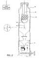
- FIG. 2is a schematic view of a dispensing apparatus usable with the present invention.
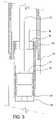
- FIG. 3is a schematic view of the apparatus of FIG. 1 . In this view, the dart and the plug has moved to a lower portion of the wellbore.
- FIG. 4is a schematic view of another aspect of the present invention.
- the optic fiberis provided with an optical sensor.
- FIG. 5is a schematic view of an apparatus according to another aspect of the present invention.
- FIG. 6is a schematic view of an apparatus according to another aspect of the present invention.
- FIG. 1is a schematic view of a partially cased wellbore 10 .
- an upper portion 20 of the wellbore 10has been lined with casing 25 , and the annular area between the casing 25 and the wellbore 10 has been filled with cement 30 .
- a lower portion 40 of the wellbore 10is in the process of being lined with a tubular 50 .
- the tubular 50is a liner 50 disposed adjacent the lower portion 40 of the wellbore 10 and at least partially overlapping the existing casing 25 .
- the liner 50is attached to a liner running tool 57 .
- a first plug 61 having a first dart (not shown) seated thereinhas traveled down the liner 50 and seated in a float valve 65 disposed at a lower portion of the liner 50 .
- a membrane in the first plug 61has ruptured, thereby allowing fluid communication between an interior of the liner 50 and the wellbore 10 .
- Disposed at an upper portion of the liner running tool 57is a second plug 62 .
- the second plug 62is selectively connected to the liner 50 until it is ready for release downhole.
- the second plug 62contains an internal bore 66 for fluid flow and a seat for mating with a second dart 72 .
- the second dart 72is shown moving along the liner running string 55 .
- the second dart 72is moved along the liner running string 55 by a wellbore fluid such as drilling mud that is pumped in behind the second dart 72 .
- the second dart 72separates the cement from the drilling mud to minimize contamination of the cement.
- the cement in front of the second dart 72is displaced into the wellbore 10 .
- An optic fiber line 80(or “fiber”) is attached to an upper portion of the second dart 72 .
- the other end of the fiber 80is coupled to a dispensing apparatus 85 disposed at the surface as shown in FIG. 2 .
- a tensionis maintained in the fiber 80 such that a fiber 80 remains substantially straight or taut as the fiber 80 is dispensed.
- a corresponding length of fiber 80is dispensed from the dispensing apparatus 85 .
- the location of the second dart 72may be determined in real time.
- a dart or plugis used herein, the aspects of the present invention are equally applicable to determining the location of other objects downhole including, but not limited to, perforating guns, retrievable packer, and other objects as known by one of ordinary skill in the art.
- FIG. 2is an exemplary dispensing apparatus 85 usable with the present invention.
- the dispensing apparatus 85is disposed inside a cementing head 90 along with the second dart 72 .
- the second dart 72has not been released into the wellbore 10 .
- one end of the fiber 80is attached to the second dart 72 and another end coupled to the dispensing apparatus 85 .
- the dispensing apparatus 85contains a release mechanism designed to dispense a length of fiber 80 that corresponds to the distance traveled by the second dart 72 .
- the amount of fiber 80 dispensedis a measurement of the linear displacement of the second dart 72 . Consequently, the location of the second dart 72 can be tracked by determining the amount of fiber 80 dispensed.
- the dispensing apparatus 85may be placed outside of the cementing head. It must be noted that other types of dispensing apparatus 85 may be used with the aspects of the present invention; for example, one such dispensing apparatus 85 is manufactured by Gas Technology Institute.
- the fiber 80may be provided with markings 84 to facilitate the reading of the length dispensed.
- one or more rollers 82may be disposed below the dispensing apparatus. As the fiber is dispensed, it will cause the roller to rotate a respective distance. The length of the fiber dispensed may be calculated from the number of revolutions made by the roller. Other methods of measuring the length of fiber dispensed known to a person of ordinary skill in the art are contemplated within the scope of the present invention.
- optic fiber line 80is its size. Generally, the fiber 80 has a smaller outer diameter than other wire products such as a wireline. As such, any fiber 80 remaining in the wellbore 10 can easily be drilled out, thereby minimizing any problems associated with materials left in the wellbore 10 . Additionally, optic fiber lines 80 are tolerant of high temperatures and corrosive environments, and thus have broad application in the oil industry. Although an optic fiber line 80 is used herein, it must be noted that the present invention also contemplates the use of similar small diameter wire transmission lines.
- the second dart 72In operation, after a desired amount of cement has been introduced into the wellbore 10 , the second dart 72 , with the optic fiber line 80 attached, is released behind the cement. Thereafter, drilling mud is pumped in behind the second dart 72 to move the second dart 72 downhole as shown in FIG. 1 . As the second dart 72 travels down the wellbore 10 , cement in front of the second dart 72 is displaced out of the liner 50 and into the wellbore 10 . Additionally, more fiber 80 is dispensed as the second dart 72 travels lower. Preferably, the tension in the fiber 80 is sufficient to maintain the fiber 80 substantially straight or taut. Consequently, the location of the second dart 72 can be determined from the length of fiber 80 dispensed.
- the second dart 72continues to move down the wellbore 10 until it seats in the second plug 62 . This stops the second dart's 72 movement in the wellbore 10 , thereby causing the fluid pressure behind the second dart 72 and the second plug 62 to build. At a predetermined level, the fluid pressure causes the second plug 62 to disconnect from the liner 50 and move down the liner 50 together with the second dart 72 and the fiber 80 .
- FIG. 3shows the second plug 62 engaged with the first plug 61 , thereby blocking off fluid communication between the interior of the liner 50 and the wellbore 10 .
- all or substantially all of the cementhave been displaced into the wellbore 10 .
- cementis prevented from flowing back into the liner 50 through the float valve 65 .
- an operator at the surfacecan compare the approximate distance between the surface and the float valve 65 to the length of fiber 80 dispensed. In this manner, the operator is provided with a positive indication that the second plug 62 has successfully reached the bottom of the liner 50 . The operator may then discontinue supplying the drilling mud into the wellbore 10 .
- the darts 72 , plugs 61 , 62 , float valve 65 , and fiber 80are drilled out.
- Other applications of the present inventioninclude attaching the fiber optic line to a dart that lands on a plug attached to a subsea casing hanger running tool. Additionally, if the cementing operation does not require the use of darts, the fiber optic line may be attached to one or more cementing plugs that are launched from the surface. It must be noted that aspects of the present invention are not limited to cementing operations, but are equally applicable to other types of wellbore operations requiring the release of an apparatus downhole.
- the optic fiber line 80may provide data regarding the wellbore 10 conditions.
- elastic properties inherent in the optic fiber 80may complicate a reading of the length of fiber 80 dispensed.
- the fiber 80may elongate or strain under the weight of the plug 62 or the drilling mud behind the plug 62 . Therefore, a true indication of the location of the plug 62 may not be achieved by reading the length of fiber 80 dispensed.
- a plug 62is used herein, aspects of the present invention are equally applicable to determining locations or positions of other apparatus disposed downhole.
- the fiber optics line 80may be equipped with one or more sensors 100 to provide a more accurate indication of the location of the dart 72 .
- a single discrete sensor 100may be disposed on the fiber 80 at a location near the dart 72 .
- the dart 72is shown traveling in a running string 55 and coupled to a dispensing apparatus 85 disposed at the surface.
- the fiber 80may also be connected to an optical signal source 110 and a receiver 120 .
- An optical signal sent from the surfacemust travel the full distance along the fiber 80 to reach the sensor 100 .
- the distancecan be determined by measuring the total time required for the signal to travel from the optical signal source 110 to the sensor 100 and then to the receiver 120 . Because the total length of fiber 80 and the amount of fiber 80 dispensed are known, any elongation of the fiber 80 due to strain may be adequately accounted for. As a result, the location of the dart 72 may be determined in real time.
- the sensor 100may also provide a means for determining the movement of the dart 72 , namely, whether it's moving or stationary. As more fiber 80 is dispensed, the fiber 80 will continue to elongate due to strain on the fiber 80 . The length of the elongated portion of fiber 80 may be measured by the sensor 100 . Thus, if the length of the fiber 80 continues to change due to strain as measured by the sensor 100 , it may indicate that the dart 72 is moving along the wellbore. If no change in the length of the fiber 80 is measured, then it may indicate that the dart 72 has stopped moving in the wellbore.
- the sensor 100may be designed to provide real time data regarding other parameters such as pressure, temperature, strain, and/or other monitored parameters of the wellbore 10 .
- perturbations in these parametersinduce a phase shift in the optical signal, which is transmitted by the sensor 120 .
- the receiver 120receives the signal, the phase shift is detected an intensity variation.
- the phase shiftis converted into the intensity change using interferometric techniques such as Mach-Zehnder, Michelson, Fabry-Perot, and Sagnac.
- multiple optical sensors 100may be arranged in a network or array configuration with individual sensors multiplexed using time division multiplexing or frequency division multiplexing.
- the network of sensorsmay provide an increased spatial resolution of temperature, pressure, strain, or flow data in the wellbore 10 .
- One form of sensor networksis known as distributed sensing.
- Distributed sensor schemestypically include Bragg grating sensors and optical time domain reflectometry (“OTDR”).
- OTDRoptical time domain reflectometry
- Bragg grating sensorsmay be formed in one or more positions along the length of the fiber 80 . These sensors provide real time data at each of these positions, which can be processed to give a clearer picture of the conditions along the length of the wellbore 10 .
- Raman OTDRmay be used to collect temperature data to provide a temperature gradient inside the wellbore 10 .
- Brillouin OTDRmay be used to measure the strain of the fiber 80 and the temperature inside the wellbore 10 . It is contemplated that other schemes of optical sensors 100 may be used without departing from the aspects of the present invention.
- the location of a dart 72may be determined from the pressure or temperature surrounding dart 72 in wellbore. As the dart 72 descends in the wellbore, the pressure or temperature of the dart 72 changes relative to the depth of the wellbore. This change in pressure or temperature may be measured by the one or more sensors 100 attached to the dart 72 . Because pressure and temperature is related to depth, the depth of the dart 72 may be determined from the pressure and/or temperature measured by the one or more sensors 100 .
- optic fibers 80may be used to transmit signals to a downhole apparatus to effect the operation thereof.
- a fiber optics line 80may be disposed along a length of the wellbore 10 . Thereafter, signals may be transmitted through the fiber 80 to operate a flapper valve 200 as illustrated in FIG. 5 .
- FIG. 5shows a flapper valve 200 disposed in a casing collar 210 .
- the fiber 80is connected to a controller 220 that, in turn, is connected to a power supply 230 and an actuator 240 of the flapper valve 200 .
- a signal from the surfacemay be transmitted through the fiber 80 and processed by the controller 220 . Thereafter, the controller 220 may operate the actuator 240 as directed by the signal.
- a downhole flapper valve 200may be activated by the fiber 80 .
- other types of downhole valvesmay be activated in this manner, including plunger valves and other types of float valves.
- the controller 220may be any computer or other programmable electronic device. It will be appreciated by those skilled in the art, however, that other types of controller may be used without departing from the scope of the present invention.
- fiber optics line 80may be used to activate a sleeve 300 .
- FIG. 6shows a sleeve 300 disposed coaxially within a casing collar 310 .
- the sleeve 300is movable between an open position and a closed position and includes one or more sleeve ports 320 formed therein. In the open position, the one or more sleeve ports 320 align with one or more casing ports 330 of the casing collar 310 , thereby allowing fluid communication between an interior of the casing collar 310 and an exterior of the casing collar 310 .
- the sleeve 300is shown in the open position.
- the sleeve ports 320are moved out of alignment with the casing ports 330 , thereby blocking fluid communication between the interior and the exterior of the casing collar 310 .
- One or more actuators 340are used to move the sleeve 300 between the open and closed positions.
- the actuator 340is connected to a power supply 350 and operated by a controller 360 connected to the fiber 80 . In this manner, signals may be transmitted through the fiber 80 to operate the sleeve 300 .
- the casing in the wellboremay be equipped with one or more magnetic or radioactive tags.
- the tagsmay be placed at predetermined positions in the casing.
- the tagsmay be used in connection with a dart having a tag sensor and an optical sensor. When the dart moves past a tag, the tag sensor may send a signal to the optical sensor. Thereafter the optical sensor may send an optical signal back to the surface through the optical fiber to indicate that the dart has moved past a certain tag in the wellbore.
- aspects of the present inventionalso contemplate using other types of transmission lines as the conveying member for the sensor.
- a sensor connected to a wiremay be disposed on an apparatus released downhole.
- the wireis spooled out from the surface by the apparatus, which may include cementing equipment such as a plug or dart, during its descent.
- the sensormay collect and transmit data regarding the wellbore.
- the wiremay transmit the signal by electrical or non-electrical means.
- the sensormay collect data regarding the wellbore such as pressure and temperature. The collected data may be used to determine the location of the apparatus downhole.
- the conveying membermay include a tube.
- a sensor attached to the tubeis disposed on an apparatus released downhole.
- the tubemay transmit information using hydraulic means supplied through the tube.
- a cablemay be used to convey the apparatus downhole. The length of the cable dispensed may be used to determine the location the apparatus downhole.
Landscapes
- Engineering & Computer Science (AREA)
- Life Sciences & Earth Sciences (AREA)
- Mining & Mineral Resources (AREA)
- Geology (AREA)
- Physics & Mathematics (AREA)
- Environmental & Geological Engineering (AREA)
- Fluid Mechanics (AREA)
- General Life Sciences & Earth Sciences (AREA)
- Geochemistry & Mineralogy (AREA)
- Remote Sensing (AREA)
- Geophysics (AREA)
- Electromagnetism (AREA)
- Length Measuring Devices By Optical Means (AREA)
- Investigating Or Analysing Materials By Optical Means (AREA)
Abstract
Description
Claims (29)
Priority Applications (3)
| Application Number | Priority Date | Filing Date | Title |
|---|---|---|---|
| US10/259,214US7219730B2 (en) | 2002-09-27 | 2002-09-27 | Smart cementing systems |
| GB0322533AGB2393465B (en) | 2002-09-27 | 2003-09-23 | Smart cementing systems |
| CA002442475ACA2442475C (en) | 2002-09-27 | 2003-09-25 | Smart cementing systems |
Applications Claiming Priority (1)
| Application Number | Priority Date | Filing Date | Title |
|---|---|---|---|
| US10/259,214US7219730B2 (en) | 2002-09-27 | 2002-09-27 | Smart cementing systems |
Publications (2)
| Publication Number | Publication Date |
|---|---|
| US20040060697A1 US20040060697A1 (en) | 2004-04-01 |
| US7219730B2true US7219730B2 (en) | 2007-05-22 |
Family
ID=29401081
Family Applications (1)
| Application Number | Title | Priority Date | Filing Date |
|---|---|---|---|
| US10/259,214Expired - Fee RelatedUS7219730B2 (en) | 2002-09-27 | 2002-09-27 | Smart cementing systems |
Country Status (3)
| Country | Link |
|---|---|
| US (1) | US7219730B2 (en) |
| CA (1) | CA2442475C (en) |
| GB (1) | GB2393465B (en) |
Cited By (58)
| Publication number | Priority date | Publication date | Assignee | Title |
|---|---|---|---|---|
| US20070234789A1 (en)* | 2006-04-05 | 2007-10-11 | Gerard Glasbergen | Fluid distribution determination and optimization with real time temperature measurement |
| US20070235199A1 (en)* | 2003-06-18 | 2007-10-11 | Logiudice Michael | Methods and apparatus for actuating a downhole tool |
| US20090277644A1 (en)* | 2008-05-09 | 2009-11-12 | Mcstay Daniel | Method and apparatus for christmas tree condition monitoring |
| US20090283261A1 (en)* | 2008-05-15 | 2009-11-19 | Schlumberger Technology Corporation | Continuous fibers for use in well completion, intervention, and other subterranean applications |
| US20090283258A1 (en)* | 2008-05-15 | 2009-11-19 | Schlumberger Technology Corporation | Continuous fibers for use in hydraulic fracturing applications |
| US20100051286A1 (en)* | 2008-09-04 | 2010-03-04 | Mcstay Daniel | Optical sensing system for wellhead equipment |
| US7857052B2 (en) | 2006-05-12 | 2010-12-28 | Weatherford/Lamb, Inc. | Stage cementing methods used in casing while drilling |
| US20110079401A1 (en)* | 2009-10-02 | 2011-04-07 | Philippe Gambier | Equipment and Methods for Deploying Line in a Wellbore |
| US8276689B2 (en) | 2006-05-22 | 2012-10-02 | Weatherford/Lamb, Inc. | Methods and apparatus for drilling with casing |
| US8505625B2 (en) | 2010-06-16 | 2013-08-13 | Halliburton Energy Services, Inc. | Controlling well operations based on monitored parameters of cement health |
| US8636063B2 (en) | 2011-02-16 | 2014-01-28 | Halliburton Energy Services, Inc. | Cement slurry monitoring |
| US8695710B2 (en) | 2011-02-10 | 2014-04-15 | Halliburton Energy Services, Inc. | Method for individually servicing a plurality of zones of a subterranean formation |
| US20140110124A1 (en)* | 2011-08-19 | 2014-04-24 | Eric Lee Goldner | Wellbore leak detection systems and methods of using the same |
| US8826980B2 (en) | 2012-03-29 | 2014-09-09 | Halliburton Energy Services, Inc. | Activation-indicating wellbore stimulation assemblies and methods of using the same |
| US8893811B2 (en) | 2011-06-08 | 2014-11-25 | Halliburton Energy Services, Inc. | Responsively activated wellbore stimulation assemblies and methods of using the same |
| US8899334B2 (en) | 2011-08-23 | 2014-12-02 | Halliburton Energy Services, Inc. | System and method for servicing a wellbore |
| US8931553B2 (en) | 2013-01-04 | 2015-01-13 | Carbo Ceramics Inc. | Electrically conductive proppant and methods for detecting, locating and characterizing the electrically conductive proppant |
| US8991509B2 (en) | 2012-04-30 | 2015-03-31 | Halliburton Energy Services, Inc. | Delayed activation activatable stimulation assembly |
| US9075155B2 (en) | 2011-04-08 | 2015-07-07 | Halliburton Energy Services, Inc. | Optical fiber based downhole seismic sensor systems and methods |
| US9127532B2 (en) | 2011-09-07 | 2015-09-08 | Halliburton Energy Services, Inc. | Optical casing collar locator systems and methods |
| US9127531B2 (en) | 2011-09-07 | 2015-09-08 | Halliburton Energy Services, Inc. | Optical casing collar locator systems and methods |
| US9228427B2 (en) | 2011-10-27 | 2016-01-05 | Saudi Arabian Oil Company | Completion method to allow dual reservoir saturation and pressure monitoring |
| US9297767B2 (en) | 2011-10-05 | 2016-03-29 | Halliburton Energy Services, Inc. | Downhole species selective optical fiber sensor systems and methods |
| US9388686B2 (en) | 2010-01-13 | 2016-07-12 | Halliburton Energy Services, Inc. | Maximizing hydrocarbon production while controlling phase behavior or precipitation of reservoir impairing liquids or solids |
| US9428976B2 (en) | 2011-02-10 | 2016-08-30 | Halliburton Energy Services, Inc. | System and method for servicing a wellbore |
| US9428998B2 (en) | 2013-11-18 | 2016-08-30 | Weatherford Technology Holdings, Llc | Telemetry operated setting tool |
| US9434875B1 (en) | 2014-12-16 | 2016-09-06 | Carbo Ceramics Inc. | Electrically-conductive proppant and methods for making and using same |
| US9476274B2 (en) | 2009-11-24 | 2016-10-25 | Maersk Olie Og Gas A/S | Apparatus and system and method of measuring data in a well extending below surface |
| US9523258B2 (en) | 2013-11-18 | 2016-12-20 | Weatherford Technology Holdings, Llc | Telemetry operated cementing plug release system |
| US9528346B2 (en) | 2013-11-18 | 2016-12-27 | Weatherford Technology Holdings, Llc | Telemetry operated ball release system |
| US9551210B2 (en) | 2014-08-15 | 2017-01-24 | Carbo Ceramics Inc. | Systems and methods for removal of electromagnetic dispersion and attenuation for imaging of proppant in an induced fracture |
| US20170204703A1 (en)* | 2014-05-27 | 2017-07-20 | Well-Sense Technology Limited | Wellbore activation system |
| US9777569B2 (en) | 2013-11-18 | 2017-10-03 | Weatherford Technology Holdings, Llc | Running tool |
| US9784070B2 (en) | 2012-06-29 | 2017-10-10 | Halliburton Energy Services, Inc. | System and method for servicing a wellbore |
| US9970290B2 (en) | 2013-11-19 | 2018-05-15 | Deep Exploration Technologies Cooperative Research Centre Ltd. | Borehole logging methods and apparatus |
| US10060250B2 (en) | 2012-03-13 | 2018-08-28 | Halliburton Energy Services, Inc. | Downhole systems and methods for water source determination |
| RU2686122C1 (en)* | 2018-06-14 | 2019-04-24 | Олег Александрович Гурин | Method of determining passage of moving objects in oil, gas and water wells and a mobile device for realizing said method |
| US10316619B2 (en) | 2017-03-16 | 2019-06-11 | Saudi Arabian Oil Company | Systems and methods for stage cementing |
| US10378339B2 (en) | 2017-11-08 | 2019-08-13 | Saudi Arabian Oil Company | Method and apparatus for controlling wellbore operations |
| US10378298B2 (en) | 2017-08-02 | 2019-08-13 | Saudi Arabian Oil Company | Vibration-induced installation of wellbore casing |
| US10487604B2 (en) | 2017-08-02 | 2019-11-26 | Saudi Arabian Oil Company | Vibration-induced installation of wellbore casing |
| US10544648B2 (en) | 2017-04-12 | 2020-01-28 | Saudi Arabian Oil Company | Systems and methods for sealing a wellbore |
| US10557330B2 (en) | 2017-04-24 | 2020-02-11 | Saudi Arabian Oil Company | Interchangeable wellbore cleaning modules |
| US10597962B2 (en) | 2017-09-28 | 2020-03-24 | Saudi Arabian Oil Company | Drilling with a whipstock system |
| US10612362B2 (en) | 2018-05-18 | 2020-04-07 | Saudi Arabian Oil Company | Coiled tubing multifunctional quad-axial visual monitoring and recording |
| US10689913B2 (en) | 2018-03-21 | 2020-06-23 | Saudi Arabian Oil Company | Supporting a string within a wellbore with a smart stabilizer |
| US10689914B2 (en) | 2018-03-21 | 2020-06-23 | Saudi Arabian Oil Company | Opening a wellbore with a smart hole-opener |
| US10794170B2 (en) | 2018-04-24 | 2020-10-06 | Saudi Arabian Oil Company | Smart system for selection of wellbore drilling fluid loss circulation material |
| US11008505B2 (en) | 2013-01-04 | 2021-05-18 | Carbo Ceramics Inc. | Electrically conductive proppant |
| US20210238980A1 (en)* | 2020-01-31 | 2021-08-05 | Halliburton Energy Services, Inc. | Fiber deployed via a top plug |
| US11131185B1 (en)* | 2020-03-27 | 2021-09-28 | Halliburton Energy Services, Inc. | System and method for deploying fiber optics lines in a wellbore |
| US11299968B2 (en) | 2020-04-06 | 2022-04-12 | Saudi Arabian Oil Company | Reducing wellbore annular pressure with a release system |
| US11396789B2 (en) | 2020-07-28 | 2022-07-26 | Saudi Arabian Oil Company | Isolating a wellbore with a wellbore isolation system |
| US11401794B2 (en) | 2018-11-13 | 2022-08-02 | Motive Drilling Technologies, Inc. | Apparatus and methods for determining information from a well |
| US11414942B2 (en) | 2020-10-14 | 2022-08-16 | Saudi Arabian Oil Company | Packer installation systems and related methods |
| US11512581B2 (en)* | 2020-01-31 | 2022-11-29 | Halliburton Energy Services, Inc. | Fiber optic sensing of wellbore leaks during cement curing using a cement plug deployment system |
| US11624265B1 (en) | 2021-11-12 | 2023-04-11 | Saudi Arabian Oil Company | Cutting pipes in wellbores using downhole autonomous jet cutting tools |
| US11649717B2 (en) | 2018-09-17 | 2023-05-16 | Saudi Arabian Oil Company | Systems and methods for sensing downhole cement sheath parameters |
Families Citing this family (89)
| Publication number | Priority date | Publication date | Assignee | Title |
|---|---|---|---|---|
| US7108084B2 (en) | 1994-10-14 | 2006-09-19 | Weatherford/Lamb, Inc. | Methods and apparatus for cementing drill strings in place for one pass drilling and completion of oil and gas wells |
| US7036610B1 (en) | 1994-10-14 | 2006-05-02 | Weatherford / Lamb, Inc. | Apparatus and method for completing oil and gas wells |
| US7040420B2 (en) | 1994-10-14 | 2006-05-09 | Weatherford/Lamb, Inc. | Methods and apparatus for cementing drill strings in place for one pass drilling and completion of oil and gas wells |
| US7100710B2 (en)* | 1994-10-14 | 2006-09-05 | Weatherford/Lamb, Inc. | Methods and apparatus for cementing drill strings in place for one pass drilling and completion of oil and gas wells |
| US7228901B2 (en) | 1994-10-14 | 2007-06-12 | Weatherford/Lamb, Inc. | Method and apparatus for cementing drill strings in place for one pass drilling and completion of oil and gas wells |
| US7013997B2 (en) | 1994-10-14 | 2006-03-21 | Weatherford/Lamb, Inc. | Methods and apparatus for cementing drill strings in place for one pass drilling and completion of oil and gas wells |
| US7147068B2 (en) | 1994-10-14 | 2006-12-12 | Weatherford / Lamb, Inc. | Methods and apparatus for cementing drill strings in place for one pass drilling and completion of oil and gas wells |
| US6868906B1 (en) | 1994-10-14 | 2005-03-22 | Weatherford/Lamb, Inc. | Closed-loop conveyance systems for well servicing |
| US6742596B2 (en) | 2001-05-17 | 2004-06-01 | Weatherford/Lamb, Inc. | Apparatus and methods for tubular makeup interlock |
| US7509722B2 (en) | 1997-09-02 | 2009-03-31 | Weatherford/Lamb, Inc. | Positioning and spinning device |
| US6536520B1 (en) | 2000-04-17 | 2003-03-25 | Weatherford/Lamb, Inc. | Top drive casing system |
| GB9815809D0 (en) | 1998-07-22 | 1998-09-16 | Appleton Robert P | Casing running tool |
| GB2340859A (en) | 1998-08-24 | 2000-03-01 | Weatherford Lamb | Method and apparatus for facilitating the connection of tubulars using a top drive |
| GB2340857A (en) | 1998-08-24 | 2000-03-01 | Weatherford Lamb | An apparatus for facilitating the connection of tubulars and alignment with a top drive |
| GB2340858A (en) | 1998-08-24 | 2000-03-01 | Weatherford Lamb | Methods and apparatus for facilitating the connection of tubulars using a top drive |
| AU772327B2 (en) | 1998-12-22 | 2004-04-22 | Weatherford Technology Holdings, Llc | Procedures and equipment for profiling and jointing of pipes |
| US7188687B2 (en) | 1998-12-22 | 2007-03-13 | Weatherford/Lamb, Inc. | Downhole filter |
| GB2345074A (en) | 1998-12-24 | 2000-06-28 | Weatherford Lamb | Floating joint to facilitate the connection of tubulars using a top drive |
| GB2347441B (en) | 1998-12-24 | 2003-03-05 | Weatherford Lamb | Apparatus and method for facilitating the connection of tubulars using a top drive |
| US6857487B2 (en) | 2002-12-30 | 2005-02-22 | Weatherford/Lamb, Inc. | Drilling with concentric strings of casing |
| US6896075B2 (en) | 2002-10-11 | 2005-05-24 | Weatherford/Lamb, Inc. | Apparatus and methods for drilling with casing |
| US7311148B2 (en) | 1999-02-25 | 2007-12-25 | Weatherford/Lamb, Inc. | Methods and apparatus for wellbore construction and completion |
| US7216727B2 (en) | 1999-12-22 | 2007-05-15 | Weatherford/Lamb, Inc. | Drilling bit for drilling while running casing |
| US7334650B2 (en) | 2000-04-13 | 2008-02-26 | Weatherford/Lamb, Inc. | Apparatus and methods for drilling a wellbore using casing |
| US7325610B2 (en)* | 2000-04-17 | 2008-02-05 | Weatherford/Lamb, Inc. | Methods and apparatus for handling and drilling with tubulars or casing |
| GB0010378D0 (en) | 2000-04-28 | 2000-06-14 | Bbl Downhole Tools Ltd | Expandable apparatus for drift and reaming a borehole |
| GB2365463B (en)* | 2000-08-01 | 2005-02-16 | Renovus Ltd | Drilling method |
| GB0206227D0 (en) | 2002-03-16 | 2002-05-01 | Weatherford Lamb | Bore-lining and drilling |
| US6994176B2 (en) | 2002-07-29 | 2006-02-07 | Weatherford/Lamb, Inc. | Adjustable rotating guides for spider or elevator |
| US6899186B2 (en) | 2002-12-13 | 2005-05-31 | Weatherford/Lamb, Inc. | Apparatus and method of drilling with casing |
| US7730965B2 (en) | 2002-12-13 | 2010-06-08 | Weatherford/Lamb, Inc. | Retractable joint and cementing shoe for use in completing a wellbore |
| US7303022B2 (en) | 2002-10-11 | 2007-12-04 | Weatherford/Lamb, Inc. | Wired casing |
| US7128154B2 (en)* | 2003-01-30 | 2006-10-31 | Weatherford/Lamb, Inc. | Single-direction cementing plug |
| USRE42877E1 (en) | 2003-02-07 | 2011-11-01 | Weatherford/Lamb, Inc. | Methods and apparatus for wellbore construction and completion |
| CA2516649C (en) | 2003-02-27 | 2010-01-19 | Weatherford/Lamb, Inc. | Drill shoe |
| GB2415722B (en) | 2003-03-05 | 2007-12-05 | Weatherford Lamb | Casing running and drilling system |
| CA2517883C (en) | 2003-03-05 | 2010-01-12 | Weatherford/Lamb, Inc. | Full bore lined wellbores |
| WO2004079147A2 (en) | 2003-03-05 | 2004-09-16 | Weatherford/Lamb, Inc. | Method and apparatus for drilling with casing |
| CA2517978C (en) | 2003-03-05 | 2009-07-14 | Weatherford/Lamb, Inc. | Drilling with casing latch |
| US7503397B2 (en) | 2004-07-30 | 2009-03-17 | Weatherford/Lamb, Inc. | Apparatus and methods of setting and retrieving casing with drilling latch and bottom hole assembly |
| WO2004090279A1 (en) | 2003-04-04 | 2004-10-21 | Weatherford/Lamb, Inc. | Method and apparatus for handling wellbore tubulars |
| US7650944B1 (en) | 2003-07-11 | 2010-01-26 | Weatherford/Lamb, Inc. | Vessel for well intervention |
| US7264067B2 (en) | 2003-10-03 | 2007-09-04 | Weatherford/Lamb, Inc. | Method of drilling and completing multiple wellbores inside a single caisson |
| US7284617B2 (en) | 2004-05-20 | 2007-10-23 | Weatherford/Lamb, Inc. | Casing running head |
| US8395782B2 (en)* | 2004-06-15 | 2013-03-12 | Optellios, Inc. | Detection and location of boundary intrusion, using composite variables derived from phase measurements |
| GB2424432B (en) | 2005-02-28 | 2010-03-17 | Weatherford Lamb | Deep water drilling with casing |
| US8269647B2 (en) | 2006-02-15 | 2012-09-18 | Schlumberger Technology Corporation | Well depth measurement using time domain reflectometry |
| CA2544457C (en) | 2006-04-21 | 2009-07-07 | Mostar Directional Technologies Inc. | System and method for downhole telemetry |
| DE602006002028D1 (en)* | 2006-05-12 | 2008-09-11 | Schlumberger Technology Bv | Method and device for locating a plug in the borehole |
| US7602668B2 (en)* | 2006-11-03 | 2009-10-13 | Schlumberger Technology Corporation | Downhole sensor networks using wireless communication |
| US8436743B2 (en)* | 2007-05-04 | 2013-05-07 | Schlumberger Technology Corporation | Method and apparatus for measuring a parameter within the well with a plug |
| US20110044574A1 (en)* | 2007-08-10 | 2011-02-24 | Andrew Strong | Methods and systems of installing cable for measurement of a physical parameter |
| US7683312B2 (en) | 2007-10-23 | 2010-03-23 | Us Sensor Systems, Inc. | Fiber-optic interrogator with normalization filters |
| GB2457934A (en)* | 2008-02-29 | 2009-09-02 | Vetco Gray Controls Ltd | Multidrop communications system using wavelength division multiplexing |
| EP2110510A1 (en)* | 2008-04-15 | 2009-10-21 | Services Pétroliers Schlumberger | Method and apparatus for measuring return flow in a well |
| US20100051264A1 (en)* | 2008-08-29 | 2010-03-04 | Baker Hughes Incorporated | Method and system for monitoring downhole completion operations |
| GB2486144A (en)* | 2009-09-02 | 2012-06-06 | Schlumberger Holdings | Equipment and methods for deploying line in a wellbore |
| US9194738B2 (en) | 2009-10-23 | 2015-11-24 | Pacific Western Bank | Fiber optic microseismic sensing systems |
| US9158032B2 (en) | 2010-02-18 | 2015-10-13 | US Seismic Systems, Inc. | Optical detection systems and methods of using the same |
| WO2011103271A2 (en) | 2010-02-18 | 2011-08-25 | US Seismic Systems, Inc. | Fiber optic personnel safety systems and methods of using the same |
| US8401354B2 (en) | 2010-02-23 | 2013-03-19 | US Seismic Systems, Inc. | Fiber optic security systems and methods of using the same |
| US8701481B2 (en) | 2010-07-06 | 2014-04-22 | US Seismic Systems, Inc. | Borehole sensing and clamping systems and methods of using the same |
| WO2012065126A2 (en)* | 2010-11-12 | 2012-05-18 | Weatherford/Lamb, Inc. | Remote operation of setting tools for liner hangers |
| WO2012103085A2 (en) | 2011-01-25 | 2012-08-02 | US Seismic Systems, Inc. | Light powered communication systems and methods of using the same |
| US9217801B2 (en) | 2011-03-08 | 2015-12-22 | Pacific Western Bank | Fiber optic acoustic sensor arrays and systems, and methods of fabricating the same |
| US8910707B2 (en)* | 2011-05-17 | 2014-12-16 | Klimack Holdings Inc. | Cement head |
| US9464520B2 (en) | 2011-05-31 | 2016-10-11 | Weatherford Technology Holdings, Llc | Method of incorporating remote communication with oilfield tubular handling apparatus |
| WO2014018959A1 (en) | 2012-07-27 | 2014-01-30 | US Seismic Systems, Inc. | Remotely actuated clamping devices for borehole seismic sensing systems and methods of operating the same |
| US9222349B2 (en)* | 2012-07-31 | 2015-12-29 | Halliburton Energy Services, Inc. | Cementing plug tracking using distributed strain sensing |
| US9228940B2 (en)* | 2012-09-14 | 2016-01-05 | Halliburton Energy Services, Inc. | Systems, methods, and apparatuses for in situ monitoring of cement fluid compositions and setting processes thereof |
| US9316091B2 (en)* | 2013-07-26 | 2016-04-19 | Weatherford/Lamb, Inc. | Electronically-actuated cementing port collar |
| NO346816B1 (en) | 2013-09-26 | 2023-01-16 | Halliburton Energy Services Inc | A well system and a method including intelligent cement wiper plugs and casing collars |
| WO2015147791A1 (en) | 2014-03-24 | 2015-10-01 | Halliburton Energy Services, Inc. | Well tools with vibratory telemetry to optical line therein |
| BR112017014959A2 (en)* | 2015-02-12 | 2018-03-13 | Halliburton Energy Services Inc | cementing head, and method and system for monitoring the location of a cement plug during a cementing operation |
| CN104847338A (en)* | 2015-03-24 | 2015-08-19 | 胜利油田长龙橡塑有限责任公司 | Ultrasonic tracking and positioning system of well cementation rubber plug |
| US10400544B2 (en)* | 2015-05-15 | 2019-09-03 | Halliburton Energy Services, Inc. | Cement plug tracking with fiber optics |
| GB201512479D0 (en)* | 2015-07-16 | 2015-08-19 | Well Sense Technology Ltd | Wellbore device |
| CA2948273C (en)* | 2015-11-11 | 2023-08-01 | Extensive Energy Technologies Partnership | Downhole valve |
| GB2563773B (en) | 2016-04-29 | 2021-07-21 | Halliburton Energy Services Inc | Restriction system for tracking downhole devices with unique pressure signals |
| WO2018022063A1 (en)* | 2016-07-28 | 2018-02-01 | Halliburton Energy Services, Inc. | Real-time plug tracking with fiber optics |
| US11149520B2 (en)* | 2016-09-22 | 2021-10-19 | Halliburton Energy Services, Inc. | Mitigation of attenuation for fiber optic sensing during cementing |
| CN107387065A (en)* | 2017-08-29 | 2017-11-24 | 西安漫垣机电设备有限公司 | A kind of cementing plug dynamic tracking instruction system and method |
| AU2017444251B2 (en)* | 2017-12-22 | 2024-04-04 | Halliburton Energy Services, Inc. | Fiber deployment system and communication |
| GB2581912B (en)* | 2017-12-26 | 2022-04-27 | Halliburton Energy Services Inc | Detachable sensor with fiber optics for cement plug |
| US11208885B2 (en)* | 2020-01-31 | 2021-12-28 | Halliburton Energy Services, Inc. | Method and system to conduct measurement while cementing |
| US20210238979A1 (en)* | 2020-01-31 | 2021-08-05 | Halliburton Energy Services, Inc. | Method and system to conduct measurement while cementing |
| US11668153B2 (en)* | 2020-01-31 | 2023-06-06 | Halliburton Energy Services, Inc. | Cement head and fiber sheath for top plug fiber deployment |
| US11448038B2 (en) | 2020-02-12 | 2022-09-20 | Halliburton Energy Services, Inc. | Reverse cementing valve system and method employing a double flapper valve with sliding sleeve and drillable nose |
| US20250277425A1 (en)* | 2024-03-01 | 2025-09-04 | Halliburton Energy Services, Inc. | Cement head flow diverter for tethered cement plug deployment |
Citations (55)
| Publication number | Priority date | Publication date | Assignee | Title |
|---|---|---|---|---|
| US1369891A (en)* | 1920-06-26 | 1921-03-01 | Erle P Halliburton | Method and means for cementing oil-wells |
| US2104270A (en)* | 1937-05-24 | 1938-01-04 | Halliburton Oil Well Cementing | Cementing equipment for wells |
| US2324698A (en)* | 1940-09-21 | 1943-07-20 | Halliburton Oil Well Cementing | Well measuring device |
| US2607222A (en)* | 1946-05-28 | 1952-08-19 | Joseph H Lane | Formation tester |
| US2681567A (en)* | 1949-12-29 | 1954-06-22 | Stanolind Oil & Gas Co | System for obtaining and transmitting measurements in wells during drilling |
| US3022822A (en)* | 1960-04-11 | 1962-02-27 | Jersey Prod Res Co | Method of manipulating well tools |
| US3426204A (en)* | 1965-07-15 | 1969-02-04 | Ralph O Sutton | Method for measuring depth of top plug in well casing cementing |
| US3457994A (en) | 1967-05-18 | 1969-07-29 | Schlumberger Technology Corp | Well packer valve structure |
| US4070734A (en)* | 1975-08-07 | 1978-01-31 | Paden Ernest D | Locking means for baling wire |
| US4121657A (en) | 1977-05-16 | 1978-10-24 | Eastman Whipstock, Inc. | Position indicator for downhole tool |
| US4206810A (en) | 1978-06-20 | 1980-06-10 | Halliburton Company | Method and apparatus for indicating the downhole arrival of a well tool |
| US4389645A (en) | 1980-09-08 | 1983-06-21 | Schlumberger Technology Corporation | Well logging fiber optic communication system |
| US4403659A (en) | 1981-04-13 | 1983-09-13 | Schlumberger Technology Corporation | Pressure controlled reversing valve |
| US4722603A (en)* | 1986-06-27 | 1988-02-02 | Chevron Research Company | Interferometric means and method for accurate determination of fiber-optic well logging cable length |
| SU1439225A1 (en)* | 1986-12-24 | 1988-11-23 | Всесоюзный научно-исследовательский институт гидрогеологии и инженерной геологии | Apparatus for measuring fluid level in well |
| US4796699A (en) | 1988-05-26 | 1989-01-10 | Schlumberger Technology Corporation | Well tool control system and method |
| US4819726A (en)* | 1985-06-10 | 1989-04-11 | Amoco Corporation | Method for indicating the position of a cement wiper plug prior to its bottomhole arrival |
| US4856595A (en) | 1988-05-26 | 1989-08-15 | Schlumberger Technology Corporation | Well tool control system and method |
| US5094103A (en)* | 1990-04-30 | 1992-03-10 | Shell Oil Company | Steam quality and flow rate measurement |
| US5294923A (en)* | 1992-01-31 | 1994-03-15 | Baker Hughes Incorporated | Method and apparatus for relaying downhole data to the surface |
| US5323856A (en) | 1993-03-31 | 1994-06-28 | Halliburton Company | Detecting system and method for oil or gas well |
| US5404948A (en)* | 1994-04-11 | 1995-04-11 | Atlantic Richfield Company | Injection well flow measurement |
| US5575333A (en) | 1995-06-07 | 1996-11-19 | Weatherford U.S., Inc. | Centralizer |
| US5768454A (en)* | 1995-12-26 | 1998-06-16 | Alcatel Alsthom Compagnie Generale D'electricite | Method of and system for writing a bragg grating point by point by point in an optical fiber |
| US5842149A (en) | 1996-10-22 | 1998-11-24 | Baker Hughes Incorporated | Closed loop drilling system |
| US5892860A (en)* | 1997-01-21 | 1999-04-06 | Cidra Corporation | Multi-parameter fiber optic sensor for use in harsh environments |
| US5904037A (en)* | 1997-06-12 | 1999-05-18 | Siecor Corporation | Fiber optic cable reversal point marking process and a marking device for use therewith |
| US5960881A (en) | 1997-04-22 | 1999-10-05 | Jerry P. Allamon | Downhole surge pressure reduction system and method of use |
| US5967231A (en) | 1997-10-31 | 1999-10-19 | Halliburton Energy Services, Inc. | Plug release indication method |
| US5986749A (en)* | 1997-09-19 | 1999-11-16 | Cidra Corporation | Fiber optic sensing system |
| US5992250A (en)* | 1996-03-29 | 1999-11-30 | Geosensor Corp. | Apparatus for the remote measurement of physical parameters |
| US6041872A (en)* | 1998-11-04 | 2000-03-28 | Gas Research Institute | Disposable telemetry cable deployment system |
| US6082459A (en) | 1998-06-29 | 2000-07-04 | Halliburton Energy Services, Inc. | Drill string diverter apparatus and method |
| US6102126A (en) | 1998-06-03 | 2000-08-15 | Schlumberger Technology Corporation | Pressure-actuated circulation valve |
| US6125935A (en) | 1996-03-28 | 2000-10-03 | Shell Oil Company | Method for monitoring well cementing operations |
| US6131658A (en) | 1998-03-16 | 2000-10-17 | Halliburton Energy Services, Inc. | Method for permanent emplacement of sensors inside casing |
| US6182764B1 (en) | 1998-05-27 | 2001-02-06 | Schlumberger Technology Corporation | Generating commands for a downhole tool using a surface fluid loop |
| US6253842B1 (en)* | 1998-09-01 | 2001-07-03 | Halliburton Energy Services, Inc. | Wireless coiled tubing joint locator |
| US6281489B1 (en)* | 1997-05-02 | 2001-08-28 | Baker Hughes Incorporated | Monitoring of downhole parameters and tools utilizing fiber optics |
| US6302203B1 (en) | 2000-03-17 | 2001-10-16 | Schlumberger Technology Corporation | Apparatus and method for communicating with devices positioned outside a liner in a wellbore |
| US6333699B1 (en) | 1998-08-28 | 2001-12-25 | Marathon Oil Company | Method and apparatus for determining position in a pipe |
| US6401814B1 (en) | 2000-11-09 | 2002-06-11 | Halliburton Energy Services, Inc. | Method of locating a cementing plug in a subterranean wall |
| US6408943B1 (en) | 2000-07-17 | 2002-06-25 | Halliburton Energy Services, Inc. | Method and apparatus for placing and interrogating downhole sensors |
| WO2002059458A2 (en) | 2000-11-03 | 2002-08-01 | Noble Engineering And Development, Ltd. | Instrumented cementing plug and system |
| US6429784B1 (en) | 1999-02-19 | 2002-08-06 | Dresser Industries, Inc. | Casing mounted sensors, actuators and generators |
| US6439306B1 (en) | 1999-02-19 | 2002-08-27 | Schlumberger Technology Corporation | Actuation of downhole devices |
| US20030010493A1 (en) | 2001-02-02 | 2003-01-16 | Hill Lawrence W. | Downhole telemetry and control system |
| US20030029611A1 (en) | 2001-08-10 | 2003-02-13 | Owens Steven C. | System and method for actuating a subterranean valve to terminate a reverse cementing operation |
| US6520257B2 (en) | 2000-12-14 | 2003-02-18 | Jerry P. Allamon | Method and apparatus for surge reduction |
| US6557630B2 (en)* | 2001-08-29 | 2003-05-06 | Sensor Highway Limited | Method and apparatus for determining the temperature of subterranean wells using fiber optic cable |
| US6585042B2 (en)* | 2001-10-01 | 2003-07-01 | Jerry L. Summers | Cementing plug location system |
| US20030127232A1 (en)* | 2001-11-14 | 2003-07-10 | Baker Hughes Incorporated | Optical position sensing for well control tools |
| US20030164237A1 (en)* | 2002-03-01 | 2003-09-04 | Butterfield Charles A. | Method, apparatus and system for selective release of cementing plugs |
| US20040047534A1 (en)* | 2002-09-09 | 2004-03-11 | Shah Vimal V. | Downhole sensing with fiber in exterior annulus |
| US6815945B2 (en) | 2000-05-11 | 2004-11-09 | Cooper Cameron Corporation | Apparatus detecting relative body movement |
Family Cites Families (1)
| Publication number | Priority date | Publication date | Assignee | Title |
|---|---|---|---|---|
| US5322856A (en)* | 1990-01-22 | 1994-06-21 | Howard Martin | Fortified glutaraldehyde chemical sterilant/disinfectant |
- 2002
- 2002-09-27USUS10/259,214patent/US7219730B2/ennot_activeExpired - Fee Related
- 2003
- 2003-09-23GBGB0322533Apatent/GB2393465B/ennot_activeExpired - Fee Related
- 2003-09-25CACA002442475Apatent/CA2442475C/ennot_activeExpired - Fee Related
Patent Citations (59)
| Publication number | Priority date | Publication date | Assignee | Title |
|---|---|---|---|---|
| US1369891A (en)* | 1920-06-26 | 1921-03-01 | Erle P Halliburton | Method and means for cementing oil-wells |
| US2104270A (en)* | 1937-05-24 | 1938-01-04 | Halliburton Oil Well Cementing | Cementing equipment for wells |
| US2324698A (en)* | 1940-09-21 | 1943-07-20 | Halliburton Oil Well Cementing | Well measuring device |
| US2607222A (en)* | 1946-05-28 | 1952-08-19 | Joseph H Lane | Formation tester |
| US2681567A (en)* | 1949-12-29 | 1954-06-22 | Stanolind Oil & Gas Co | System for obtaining and transmitting measurements in wells during drilling |
| US3022822A (en)* | 1960-04-11 | 1962-02-27 | Jersey Prod Res Co | Method of manipulating well tools |
| US3426204A (en)* | 1965-07-15 | 1969-02-04 | Ralph O Sutton | Method for measuring depth of top plug in well casing cementing |
| US3457994A (en) | 1967-05-18 | 1969-07-29 | Schlumberger Technology Corp | Well packer valve structure |
| US4070734A (en)* | 1975-08-07 | 1978-01-31 | Paden Ernest D | Locking means for baling wire |
| US4121657A (en) | 1977-05-16 | 1978-10-24 | Eastman Whipstock, Inc. | Position indicator for downhole tool |
| US4206810A (en) | 1978-06-20 | 1980-06-10 | Halliburton Company | Method and apparatus for indicating the downhole arrival of a well tool |
| US4389645A (en) | 1980-09-08 | 1983-06-21 | Schlumberger Technology Corporation | Well logging fiber optic communication system |
| US4403659A (en) | 1981-04-13 | 1983-09-13 | Schlumberger Technology Corporation | Pressure controlled reversing valve |
| US4819726A (en)* | 1985-06-10 | 1989-04-11 | Amoco Corporation | Method for indicating the position of a cement wiper plug prior to its bottomhole arrival |
| US4722603A (en)* | 1986-06-27 | 1988-02-02 | Chevron Research Company | Interferometric means and method for accurate determination of fiber-optic well logging cable length |
| SU1439225A1 (en)* | 1986-12-24 | 1988-11-23 | Всесоюзный научно-исследовательский институт гидрогеологии и инженерной геологии | Apparatus for measuring fluid level in well |
| US4796699A (en) | 1988-05-26 | 1989-01-10 | Schlumberger Technology Corporation | Well tool control system and method |
| US4856595A (en) | 1988-05-26 | 1989-08-15 | Schlumberger Technology Corporation | Well tool control system and method |
| US5094103A (en)* | 1990-04-30 | 1992-03-10 | Shell Oil Company | Steam quality and flow rate measurement |
| US5294923A (en)* | 1992-01-31 | 1994-03-15 | Baker Hughes Incorporated | Method and apparatus for relaying downhole data to the surface |
| US5323856A (en) | 1993-03-31 | 1994-06-28 | Halliburton Company | Detecting system and method for oil or gas well |
| US5404948A (en)* | 1994-04-11 | 1995-04-11 | Atlantic Richfield Company | Injection well flow measurement |
| US5575333A (en) | 1995-06-07 | 1996-11-19 | Weatherford U.S., Inc. | Centralizer |
| US5768454A (en)* | 1995-12-26 | 1998-06-16 | Alcatel Alsthom Compagnie Generale D'electricite | Method of and system for writing a bragg grating point by point by point in an optical fiber |
| US6125935A (en) | 1996-03-28 | 2000-10-03 | Shell Oil Company | Method for monitoring well cementing operations |
| US5992250A (en)* | 1996-03-29 | 1999-11-30 | Geosensor Corp. | Apparatus for the remote measurement of physical parameters |
| US5842149A (en) | 1996-10-22 | 1998-11-24 | Baker Hughes Incorporated | Closed loop drilling system |
| US5892860A (en)* | 1997-01-21 | 1999-04-06 | Cidra Corporation | Multi-parameter fiber optic sensor for use in harsh environments |
| US5960881A (en) | 1997-04-22 | 1999-10-05 | Jerry P. Allamon | Downhole surge pressure reduction system and method of use |
| US6281489B1 (en)* | 1997-05-02 | 2001-08-28 | Baker Hughes Incorporated | Monitoring of downhole parameters and tools utilizing fiber optics |
| US5904037A (en)* | 1997-06-12 | 1999-05-18 | Siecor Corporation | Fiber optic cable reversal point marking process and a marking device for use therewith |
| US5986749A (en)* | 1997-09-19 | 1999-11-16 | Cidra Corporation | Fiber optic sensing system |
| US5967231A (en) | 1997-10-31 | 1999-10-19 | Halliburton Energy Services, Inc. | Plug release indication method |
| US6131658A (en) | 1998-03-16 | 2000-10-17 | Halliburton Energy Services, Inc. | Method for permanent emplacement of sensors inside casing |
| US6182764B1 (en) | 1998-05-27 | 2001-02-06 | Schlumberger Technology Corporation | Generating commands for a downhole tool using a surface fluid loop |
| US6102126A (en) | 1998-06-03 | 2000-08-15 | Schlumberger Technology Corporation | Pressure-actuated circulation valve |
| US6082459A (en) | 1998-06-29 | 2000-07-04 | Halliburton Energy Services, Inc. | Drill string diverter apparatus and method |
| US6333699B1 (en) | 1998-08-28 | 2001-12-25 | Marathon Oil Company | Method and apparatus for determining position in a pipe |
| US6253842B1 (en)* | 1998-09-01 | 2001-07-03 | Halliburton Energy Services, Inc. | Wireless coiled tubing joint locator |
| US6041872A (en)* | 1998-11-04 | 2000-03-28 | Gas Research Institute | Disposable telemetry cable deployment system |
| US6439306B1 (en) | 1999-02-19 | 2002-08-27 | Schlumberger Technology Corporation | Actuation of downhole devices |
| US6429784B1 (en) | 1999-02-19 | 2002-08-06 | Dresser Industries, Inc. | Casing mounted sensors, actuators and generators |
| US6302203B1 (en) | 2000-03-17 | 2001-10-16 | Schlumberger Technology Corporation | Apparatus and method for communicating with devices positioned outside a liner in a wellbore |
| US6378610B2 (en) | 2000-03-17 | 2002-04-30 | Schlumberger Technology Corp. | Communicating with devices positioned outside a liner in a wellbore |
| US6815945B2 (en) | 2000-05-11 | 2004-11-09 | Cooper Cameron Corporation | Apparatus detecting relative body movement |
| US6408943B1 (en) | 2000-07-17 | 2002-06-25 | Halliburton Energy Services, Inc. | Method and apparatus for placing and interrogating downhole sensors |
| WO2002059458A2 (en) | 2000-11-03 | 2002-08-01 | Noble Engineering And Development, Ltd. | Instrumented cementing plug and system |
| US20020157828A1 (en) | 2000-11-03 | 2002-10-31 | King Charles H. | Instrumented cementing plug and system |
| US6634425B2 (en)* | 2000-11-03 | 2003-10-21 | Noble Engineering & Development, Ltd. | Instrumented cementing plug and system |
| US6401814B1 (en) | 2000-11-09 | 2002-06-11 | Halliburton Energy Services, Inc. | Method of locating a cementing plug in a subterranean wall |
| US6520257B2 (en) | 2000-12-14 | 2003-02-18 | Jerry P. Allamon | Method and apparatus for surge reduction |
| US20030010493A1 (en) | 2001-02-02 | 2003-01-16 | Hill Lawrence W. | Downhole telemetry and control system |
| US20030029611A1 (en) | 2001-08-10 | 2003-02-13 | Owens Steven C. | System and method for actuating a subterranean valve to terminate a reverse cementing operation |
| US6557630B2 (en)* | 2001-08-29 | 2003-05-06 | Sensor Highway Limited | Method and apparatus for determining the temperature of subterranean wells using fiber optic cable |
| US6585042B2 (en)* | 2001-10-01 | 2003-07-01 | Jerry L. Summers | Cementing plug location system |
| US20030127232A1 (en)* | 2001-11-14 | 2003-07-10 | Baker Hughes Incorporated | Optical position sensing for well control tools |
| US20030164237A1 (en)* | 2002-03-01 | 2003-09-04 | Butterfield Charles A. | Method, apparatus and system for selective release of cementing plugs |
| US20040047534A1 (en)* | 2002-09-09 | 2004-03-11 | Shah Vimal V. | Downhole sensing with fiber in exterior annulus |
| US6847034B2 (en) | 2002-09-09 | 2005-01-25 | Halliburton Energy Services, Inc. | Downhole sensing with fiber in exterior annulus |
Non-Patent Citations (6)
| Title |
|---|
| "The Final Frontier: Fiber Optics Promise Real-Time Information On Well Drilling," GTI Journal, Winter/Spring 2002. |
| Canadian Office Action, Application No. 2,442,475, dated Feb. 21, 2006. |
| GTI's Friction Brake. |
| PCT Search Report, Application No. GB 0322533.1, dated Jan. 6, 2004. |
| U.S. Appl. No. 10/464,433, filed Jun. 18, 2003, LoGiudice, et al. |
| U.S. Appl. No. 60/332,478, filed Nov. 2001, Bussear et al.* |
Cited By (78)
| Publication number | Priority date | Publication date | Assignee | Title |
|---|---|---|---|---|
| US20070235199A1 (en)* | 2003-06-18 | 2007-10-11 | Logiudice Michael | Methods and apparatus for actuating a downhole tool |
| US7503398B2 (en) | 2003-06-18 | 2009-03-17 | Weatherford/Lamb, Inc. | Methods and apparatus for actuating a downhole tool |
| US20070234789A1 (en)* | 2006-04-05 | 2007-10-11 | Gerard Glasbergen | Fluid distribution determination and optimization with real time temperature measurement |
| US7857052B2 (en) | 2006-05-12 | 2010-12-28 | Weatherford/Lamb, Inc. | Stage cementing methods used in casing while drilling |
| US8276689B2 (en) | 2006-05-22 | 2012-10-02 | Weatherford/Lamb, Inc. | Methods and apparatus for drilling with casing |
| US20090277644A1 (en)* | 2008-05-09 | 2009-11-12 | Mcstay Daniel | Method and apparatus for christmas tree condition monitoring |
| US7967066B2 (en) | 2008-05-09 | 2011-06-28 | Fmc Technologies, Inc. | Method and apparatus for Christmas tree condition monitoring |
| US7942202B2 (en)* | 2008-05-15 | 2011-05-17 | Schlumberger Technology Corporation | Continuous fibers for use in well completion, intervention, and other subterranean applications |
| US20090283261A1 (en)* | 2008-05-15 | 2009-11-19 | Schlumberger Technology Corporation | Continuous fibers for use in well completion, intervention, and other subterranean applications |
| US20090283258A1 (en)* | 2008-05-15 | 2009-11-19 | Schlumberger Technology Corporation | Continuous fibers for use in hydraulic fracturing applications |
| US7926562B2 (en)* | 2008-05-15 | 2011-04-19 | Schlumberger Technology Corporation | Continuous fibers for use in hydraulic fracturing applications |
| US20100051286A1 (en)* | 2008-09-04 | 2010-03-04 | Mcstay Daniel | Optical sensing system for wellhead equipment |
| US7845404B2 (en)* | 2008-09-04 | 2010-12-07 | Fmc Technologies, Inc. | Optical sensing system for wellhead equipment |
| US20110079401A1 (en)* | 2009-10-02 | 2011-04-07 | Philippe Gambier | Equipment and Methods for Deploying Line in a Wellbore |
| US9476274B2 (en) | 2009-11-24 | 2016-10-25 | Maersk Olie Og Gas A/S | Apparatus and system and method of measuring data in a well extending below surface |
| US9388686B2 (en) | 2010-01-13 | 2016-07-12 | Halliburton Energy Services, Inc. | Maximizing hydrocarbon production while controlling phase behavior or precipitation of reservoir impairing liquids or solids |
| US8505625B2 (en) | 2010-06-16 | 2013-08-13 | Halliburton Energy Services, Inc. | Controlling well operations based on monitored parameters of cement health |
| US9458697B2 (en) | 2011-02-10 | 2016-10-04 | Halliburton Energy Services, Inc. | Method for individually servicing a plurality of zones of a subterranean formation |
| US8695710B2 (en) | 2011-02-10 | 2014-04-15 | Halliburton Energy Services, Inc. | Method for individually servicing a plurality of zones of a subterranean formation |
| US9428976B2 (en) | 2011-02-10 | 2016-08-30 | Halliburton Energy Services, Inc. | System and method for servicing a wellbore |
| US8636063B2 (en) | 2011-02-16 | 2014-01-28 | Halliburton Energy Services, Inc. | Cement slurry monitoring |
| US9075155B2 (en) | 2011-04-08 | 2015-07-07 | Halliburton Energy Services, Inc. | Optical fiber based downhole seismic sensor systems and methods |
| US8893811B2 (en) | 2011-06-08 | 2014-11-25 | Halliburton Energy Services, Inc. | Responsively activated wellbore stimulation assemblies and methods of using the same |
| US20140110124A1 (en)* | 2011-08-19 | 2014-04-24 | Eric Lee Goldner | Wellbore leak detection systems and methods of using the same |
| US8899334B2 (en) | 2011-08-23 | 2014-12-02 | Halliburton Energy Services, Inc. | System and method for servicing a wellbore |
| US9127532B2 (en) | 2011-09-07 | 2015-09-08 | Halliburton Energy Services, Inc. | Optical casing collar locator systems and methods |
| US9127531B2 (en) | 2011-09-07 | 2015-09-08 | Halliburton Energy Services, Inc. | Optical casing collar locator systems and methods |
| US9297767B2 (en) | 2011-10-05 | 2016-03-29 | Halliburton Energy Services, Inc. | Downhole species selective optical fiber sensor systems and methods |
| US9228427B2 (en) | 2011-10-27 | 2016-01-05 | Saudi Arabian Oil Company | Completion method to allow dual reservoir saturation and pressure monitoring |
| US10060250B2 (en) | 2012-03-13 | 2018-08-28 | Halliburton Energy Services, Inc. | Downhole systems and methods for water source determination |
| US8826980B2 (en) | 2012-03-29 | 2014-09-09 | Halliburton Energy Services, Inc. | Activation-indicating wellbore stimulation assemblies and methods of using the same |
| US8991509B2 (en) | 2012-04-30 | 2015-03-31 | Halliburton Energy Services, Inc. | Delayed activation activatable stimulation assembly |
| US9784070B2 (en) | 2012-06-29 | 2017-10-10 | Halliburton Energy Services, Inc. | System and method for servicing a wellbore |
| US11993749B2 (en) | 2013-01-04 | 2024-05-28 | National Technology & Engineering Solutions Of Sandia, Llc | Electrically conductive proppant and methods for detecting, locating and characterizing the electrically conductive proppant |
| US11162022B2 (en) | 2013-01-04 | 2021-11-02 | Carbo Ceramics Inc. | Electrically conductive proppant and methods for detecting, locating and characterizing the electrically conductive proppant |
| US8931553B2 (en) | 2013-01-04 | 2015-01-13 | Carbo Ceramics Inc. | Electrically conductive proppant and methods for detecting, locating and characterizing the electrically conductive proppant |
| US11008505B2 (en) | 2013-01-04 | 2021-05-18 | Carbo Ceramics Inc. | Electrically conductive proppant |
| US10538695B2 (en) | 2013-01-04 | 2020-01-21 | Carbo Ceramics Inc. | Electrically conductive proppant and methods for detecting, locating and characterizing the electrically conductive proppant |
| US9777569B2 (en) | 2013-11-18 | 2017-10-03 | Weatherford Technology Holdings, Llc | Running tool |
| US9970251B2 (en) | 2013-11-18 | 2018-05-15 | Weatherford Technology Holdings, Llc | Telemetry operated setting tool |
| US9523258B2 (en) | 2013-11-18 | 2016-12-20 | Weatherford Technology Holdings, Llc | Telemetry operated cementing plug release system |
| US9528346B2 (en) | 2013-11-18 | 2016-12-27 | Weatherford Technology Holdings, Llc | Telemetry operated ball release system |
| US10221638B2 (en) | 2013-11-18 | 2019-03-05 | Weatherford Technology Holdings, Llc | Telemetry operated cementing plug release system |
| US10246965B2 (en) | 2013-11-18 | 2019-04-02 | Weatherford Technology Holdings, Llc | Telemetry operated ball release system |
| US9428998B2 (en) | 2013-11-18 | 2016-08-30 | Weatherford Technology Holdings, Llc | Telemetry operated setting tool |
| US10422216B2 (en) | 2013-11-18 | 2019-09-24 | Weatherford Technology Holdings, Llc | Telemetry operated running tool |
| US10415378B2 (en) | 2013-11-19 | 2019-09-17 | Minex Crc Ltd | Borehole logging methods and apparatus |
| US9970290B2 (en) | 2013-11-19 | 2018-05-15 | Deep Exploration Technologies Cooperative Research Centre Ltd. | Borehole logging methods and apparatus |
| US20170204703A1 (en)* | 2014-05-27 | 2017-07-20 | Well-Sense Technology Limited | Wellbore activation system |
| US10514478B2 (en) | 2014-08-15 | 2019-12-24 | Carbo Ceramics, Inc | Systems and methods for removal of electromagnetic dispersion and attenuation for imaging of proppant in an induced fracture |
| US9551210B2 (en) | 2014-08-15 | 2017-01-24 | Carbo Ceramics Inc. | Systems and methods for removal of electromagnetic dispersion and attenuation for imaging of proppant in an induced fracture |
| US9434875B1 (en) | 2014-12-16 | 2016-09-06 | Carbo Ceramics Inc. | Electrically-conductive proppant and methods for making and using same |
| US10167422B2 (en) | 2014-12-16 | 2019-01-01 | Carbo Ceramics Inc. | Electrically-conductive proppant and methods for detecting, locating and characterizing the electrically-conductive proppant |
| US10316619B2 (en) | 2017-03-16 | 2019-06-11 | Saudi Arabian Oil Company | Systems and methods for stage cementing |
| US10544648B2 (en) | 2017-04-12 | 2020-01-28 | Saudi Arabian Oil Company | Systems and methods for sealing a wellbore |
| US10557330B2 (en) | 2017-04-24 | 2020-02-11 | Saudi Arabian Oil Company | Interchangeable wellbore cleaning modules |
| US10378298B2 (en) | 2017-08-02 | 2019-08-13 | Saudi Arabian Oil Company | Vibration-induced installation of wellbore casing |
| US10487604B2 (en) | 2017-08-02 | 2019-11-26 | Saudi Arabian Oil Company | Vibration-induced installation of wellbore casing |
| US10920517B2 (en) | 2017-08-02 | 2021-02-16 | Saudi Arabian Oil Company | Vibration-induced installation of wellbore casing |
| US10597962B2 (en) | 2017-09-28 | 2020-03-24 | Saudi Arabian Oil Company | Drilling with a whipstock system |
| US10378339B2 (en) | 2017-11-08 | 2019-08-13 | Saudi Arabian Oil Company | Method and apparatus for controlling wellbore operations |
| US10689913B2 (en) | 2018-03-21 | 2020-06-23 | Saudi Arabian Oil Company | Supporting a string within a wellbore with a smart stabilizer |
| US10689914B2 (en) | 2018-03-21 | 2020-06-23 | Saudi Arabian Oil Company | Opening a wellbore with a smart hole-opener |
| US10794170B2 (en) | 2018-04-24 | 2020-10-06 | Saudi Arabian Oil Company | Smart system for selection of wellbore drilling fluid loss circulation material |
| US11268369B2 (en) | 2018-04-24 | 2022-03-08 | Saudi Arabian Oil Company | Smart system for selection of wellbore drilling fluid loss circulation material |
| US10612362B2 (en) | 2018-05-18 | 2020-04-07 | Saudi Arabian Oil Company | Coiled tubing multifunctional quad-axial visual monitoring and recording |
| RU2686122C1 (en)* | 2018-06-14 | 2019-04-24 | Олег Александрович Гурин | Method of determining passage of moving objects in oil, gas and water wells and a mobile device for realizing said method |
| WO2019240613A1 (en)* | 2018-06-14 | 2019-12-19 | Gurin Oleg Alexandrovich | Method and device for determining the passage of moving objects in wells |
| US11649717B2 (en) | 2018-09-17 | 2023-05-16 | Saudi Arabian Oil Company | Systems and methods for sensing downhole cement sheath parameters |
| US11401794B2 (en) | 2018-11-13 | 2022-08-02 | Motive Drilling Technologies, Inc. | Apparatus and methods for determining information from a well |
| US11988083B2 (en) | 2018-11-13 | 2024-05-21 | Motive Drilling Technologies, Inc. | Apparatus and methods for determining information from a well |
| US11512581B2 (en)* | 2020-01-31 | 2022-11-29 | Halliburton Energy Services, Inc. | Fiber optic sensing of wellbore leaks during cement curing using a cement plug deployment system |
| US20210238980A1 (en)* | 2020-01-31 | 2021-08-05 | Halliburton Energy Services, Inc. | Fiber deployed via a top plug |
| US11131185B1 (en)* | 2020-03-27 | 2021-09-28 | Halliburton Energy Services, Inc. | System and method for deploying fiber optics lines in a wellbore |
| US11299968B2 (en) | 2020-04-06 | 2022-04-12 | Saudi Arabian Oil Company | Reducing wellbore annular pressure with a release system |
| US11396789B2 (en) | 2020-07-28 | 2022-07-26 | Saudi Arabian Oil Company | Isolating a wellbore with a wellbore isolation system |
| US11414942B2 (en) | 2020-10-14 | 2022-08-16 | Saudi Arabian Oil Company | Packer installation systems and related methods |
| US11624265B1 (en) | 2021-11-12 | 2023-04-11 | Saudi Arabian Oil Company | Cutting pipes in wellbores using downhole autonomous jet cutting tools |
Also Published As
| Publication number | Publication date |
|---|---|
| US20040060697A1 (en) | 2004-04-01 |
| GB0322533D0 (en) | 2003-10-29 |
| GB2393465B (en) | 2006-05-10 |
| CA2442475C (en) | 2007-07-03 |
| GB2393465A (en) | 2004-03-31 |
| CA2442475A1 (en) | 2004-03-27 |
Similar Documents
| Publication | Publication Date | Title |
|---|---|---|
| US7219730B2 (en) | Smart cementing systems | |
| CN101405474B (en) | Method and apparatus for locating a plug within the well | |
| US8436743B2 (en) | Method and apparatus for measuring a parameter within the well with a plug | |
| US10655456B2 (en) | Apparatus for monitoring at least a portion of a wellbore | |
| US5626192A (en) | Coiled tubing joint locator and methods | |
| EP2401475B1 (en) | System and method for wellbore monitoring | |
| CA2332241C (en) | Wireless coiled tubing joint locator | |
| EP2192263A1 (en) | Method for monitoring cement plugs | |
| NO339196B1 (en) | Use of fiber optics in coiled tubing in wells in the underground | |
| US20210238979A1 (en) | Method and system to conduct measurement while cementing | |
| US20150323700A1 (en) | In-Situ System Calibration | |
| US20140124197A1 (en) | Systems and methods for maneuvering downhole tools in a subsea well | |
| US20150338301A1 (en) | Method and Device for Determining Pressure in a Cavity | |
| CA2482487C (en) | Permanent downhole deployment of optical sensors | |
| MX2008010622A (en) | Method and apparatus for locating a plug within the well |
Legal Events
| Date | Code | Title | Description |
|---|---|---|---|
| AS | Assignment | Owner name:WEATHERFORD/LAMB, INC., TEXAS Free format text:ASSIGNMENT OF ASSIGNORS INTEREST;ASSIGNORS:TILTON, FREDERICK T.;LIRETTE, BRENT J.;MARTENS, JAMES G.;REEL/FRAME:013557/0317 Effective date:20021122 | |
| STCF | Information on status: patent grant | Free format text:PATENTED CASE | |
| FEPP | Fee payment procedure | Free format text:PAYER NUMBER DE-ASSIGNED (ORIGINAL EVENT CODE: RMPN); ENTITY STATUS OF PATENT OWNER: LARGE ENTITY Free format text:PAYOR NUMBER ASSIGNED (ORIGINAL EVENT CODE: ASPN); ENTITY STATUS OF PATENT OWNER: LARGE ENTITY | |
| FPAY | Fee payment | Year of fee payment:4 | |
| FPAY | Fee payment | Year of fee payment:8 | |
| AS | Assignment | Owner name:WEATHERFORD TECHNOLOGY HOLDINGS, LLC, TEXAS Free format text:ASSIGNMENT OF ASSIGNORS INTEREST;ASSIGNOR:WEATHERFORD/LAMB, INC.;REEL/FRAME:034526/0272 Effective date:20140901 | |
| FEPP | Fee payment procedure | Free format text:MAINTENANCE FEE REMINDER MAILED (ORIGINAL EVENT CODE: REM.); ENTITY STATUS OF PATENT OWNER: LARGE ENTITY | |
| LAPS | Lapse for failure to pay maintenance fees | Free format text:PATENT EXPIRED FOR FAILURE TO PAY MAINTENANCE FEES (ORIGINAL EVENT CODE: EXP.); ENTITY STATUS OF PATENT OWNER: LARGE ENTITY | |
| STCH | Information on status: patent discontinuation | Free format text:PATENT EXPIRED DUE TO NONPAYMENT OF MAINTENANCE FEES UNDER 37 CFR 1.362 | |
| FP | Lapsed due to failure to pay maintenance fee | Effective date:20190522 |