US7218691B1 - Method and apparatus for estimation of orthogonal frequency division multiplexing symbol timing and carrier frequency offset - Google Patents
Method and apparatus for estimation of orthogonal frequency division multiplexing symbol timing and carrier frequency offsetDownload PDFInfo
- Publication number
- US7218691B1 US7218691B1US10/067,556US6755602AUS7218691B1US 7218691 B1US7218691 B1US 7218691B1US 6755602 AUS6755602 AUS 6755602AUS 7218691 B1US7218691 B1US 7218691B1
- Authority
- US
- United States
- Prior art keywords
- carrier frequency
- frequency offset
- correlation signal
- training symbols
- value
- Prior art date
- Legal status (The legal status is an assumption and is not a legal conclusion. Google has not performed a legal analysis and makes no representation as to the accuracy of the status listed.)
- Expired - Lifetime, expires
Links
- 238000000034methodMethods0.000titleclaimsabstractdescription58
- 238000012549trainingMethods0.000claimsabstractdescription87
- 238000005070samplingMethods0.000claimsdescription41
- 230000006978adaptationEffects0.000claimsdescription7
- 230000000875corresponding effectEffects0.000description8
- 238000001514detection methodMethods0.000description7
- 238000010586diagramMethods0.000description6
- 125000004122cyclic groupChemical group0.000description4
- 238000011084recoveryMethods0.000description4
- 230000007423decreaseEffects0.000description2
- 238000012545processingMethods0.000description2
- 238000007476Maximum LikelihoodMethods0.000description1
- 230000005540biological transmissionEffects0.000description1
- 238000012937correctionMethods0.000description1
- 230000002596correlated effectEffects0.000description1
- 238000012986modificationMethods0.000description1
- 230000004048modificationEffects0.000description1
- 208000005632oculopharyngodistal myopathyDiseases0.000description1
- 230000010363phase shiftEffects0.000description1
- 238000013139quantizationMethods0.000description1
- 238000001228spectrumMethods0.000description1
Images


Classifications
- H—ELECTRICITY
- H04—ELECTRIC COMMUNICATION TECHNIQUE
- H04L—TRANSMISSION OF DIGITAL INFORMATION, e.g. TELEGRAPHIC COMMUNICATION
- H04L27/00—Modulated-carrier systems
- H04L27/26—Systems using multi-frequency codes
- H04L27/2601—Multicarrier modulation systems
- H04L27/2647—Arrangements specific to the receiver only
- H04L27/2655—Synchronisation arrangements
- H04L27/2657—Carrier synchronisation
- H04L27/266—Fine or fractional frequency offset determination and synchronisation
- H—ELECTRICITY
- H04—ELECTRIC COMMUNICATION TECHNIQUE
- H04L—TRANSMISSION OF DIGITAL INFORMATION, e.g. TELEGRAPHIC COMMUNICATION
- H04L25/00—Baseband systems
- H04L25/02—Details ; arrangements for supplying electrical power along data transmission lines
- H04L25/0202—Channel estimation
- H04L25/0224—Channel estimation using sounding signals
- H04L25/0228—Channel estimation using sounding signals with direct estimation from sounding signals
- H—ELECTRICITY
- H04—ELECTRIC COMMUNICATION TECHNIQUE
- H04L—TRANSMISSION OF DIGITAL INFORMATION, e.g. TELEGRAPHIC COMMUNICATION
- H04L27/00—Modulated-carrier systems
- H04L27/26—Systems using multi-frequency codes
- H04L27/2601—Multicarrier modulation systems
- H04L27/2647—Arrangements specific to the receiver only
- H04L27/2655—Synchronisation arrangements
- H04L27/2657—Carrier synchronisation
- H04L27/2659—Coarse or integer frequency offset determination and synchronisation
- H—ELECTRICITY
- H04—ELECTRIC COMMUNICATION TECHNIQUE
- H04L—TRANSMISSION OF DIGITAL INFORMATION, e.g. TELEGRAPHIC COMMUNICATION
- H04L27/00—Modulated-carrier systems
- H04L27/26—Systems using multi-frequency codes
- H04L27/2601—Multicarrier modulation systems
- H04L27/2647—Arrangements specific to the receiver only
- H04L27/2655—Synchronisation arrangements
- H04L27/2662—Symbol synchronisation
- H—ELECTRICITY
- H04—ELECTRIC COMMUNICATION TECHNIQUE
- H04L—TRANSMISSION OF DIGITAL INFORMATION, e.g. TELEGRAPHIC COMMUNICATION
- H04L27/00—Modulated-carrier systems
- H04L27/26—Systems using multi-frequency codes
- H04L27/2601—Multicarrier modulation systems
- H04L27/2647—Arrangements specific to the receiver only
- H04L27/2655—Synchronisation arrangements
- H04L27/2668—Details of algorithms
- H04L27/2673—Details of algorithms characterised by synchronisation parameters
- H04L27/2675—Pilot or known symbols
- H—ELECTRICITY
- H04—ELECTRIC COMMUNICATION TECHNIQUE
- H04L—TRANSMISSION OF DIGITAL INFORMATION, e.g. TELEGRAPHIC COMMUNICATION
- H04L27/00—Modulated-carrier systems
- H04L27/26—Systems using multi-frequency codes
- H04L27/2601—Multicarrier modulation systems
- H04L27/2647—Arrangements specific to the receiver only
- H04L27/2655—Synchronisation arrangements
- H04L27/2689—Link with other circuits, i.e. special connections between synchronisation arrangements and other circuits for achieving synchronisation
- H04L27/2695—Link with other circuits, i.e. special connections between synchronisation arrangements and other circuits for achieving synchronisation with channel estimation, e.g. determination of delay spread, derivative or peak tracking
Definitions
- the present inventionrelates to receivers, and more particularly to receivers that measure carrier frequency offset, symbol timing and/or phase noise of an orthogonal frequency division multiplexing signal.
- a wireless local area networkuses radio frequency (RF) signals to transmit and receive data between electronic devices.
- WLANsprovide all of the features and benefits of traditional hard-wired LANs without requiring cable connections between the devices.
- transmitters and receivers(often implemented as wireless network interface cards) provide a wireless interface between a client and a wireless access point to create a transparent connection between the client and the network.
- the WLANprovides a wireless interface directly between two devices.
- the access pointis the wireless equivalent of a hub.
- the access pointis typically connected to the WLAN backbone through a standard Ethernet cable and communicates with the wireless devices using an antenna.
- the wireless access pointmaintains the connections to clients that are located in a coverage area of the access point.
- the wireless access pointalso typically handles security by granting or denying access.
- a low bandoperates at frequencies from 5.15 to 5.25 GHz with a maximum power output of 50 mW.
- a middle bandoperates at frequencies from 5.25 to 5.35 GHz with a maximum power output of 250 mW.
- a high bandoperates at frequencies from 5.75 to 5.85 GHz with a maximum power output of 1000 mW.
- IEEE section 802.11(a)employs orthogonal frequency division multiplexing (OFDM) instead of direct sequence spread spectrum (DSSS) that is employed by IEEE section 802.11(b). OFDM provides higher data rates and reduces transmission echo and distortion that are caused by multipath propagation and radio frequency interference (RFI).
- OFDMorthogonal frequency division multiplexing
- DSSSdirect sequence spread spectrum
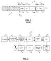
- data packetsinclude a preamble 10 that is specified by IEEE section 802.11(a).
- the preamble 10includes a plurality of short training symbols 12 (S 0 , . . . , S 9 ).
- the short training symbols 12are followed by a guard interval 14 (Guard) and two long training symbols 16 - 1 and 16 - 2 (L 0 , L 1 ).
- the duration of the short training symbol 12is T short
- the duration of the guard interval 14is T G12
- the duration of the long training symbols 16is T long
- the duration of the guard interval 15 for data symbolsis T G1
- the duration of data symbols 18is T data .
- Guard intervals 15 and data symbols 18alternate after the long training symbols 16 .
- T short0.8 ⁇ s
- T G10.8 ⁇ s
- T G121.6 ⁇ s
- T long3.2 ⁇ s
- T data4 ⁇ s.
- Symbol timingis needed to determine the samples of each OFDM symbol that correspond to the guard interval and the samples that are used for fast Fourier transform (FFT) processing. Compensation of the carrier frequency offset is also needed to maximize signal amplitude and minimize inter-carrier interference (ICI).
- FFTfast Fourier transform
- Conventional symbol timing circuitscorrelate two halves of a single OFDM training symbol whose duration is equal to the duration of the data symbols. For example, see the symbol timing circuit disclosed in T. Schmidl and D.C. Cox, “Robust Frequency and Timing Synchronization for OFDM”, IEEE Trans. Commun., vol. 45, no. 12, (December 1999), pp. 1613–1621, which is hereby incorporated by reference.
- the conventional symbol timing circuitexhibits a plateau when there is no intersymbol interference (ISI).
- the duration of the plateauis the duration of the guard interval that is not affected by ISI.
- the plateau in the conventional symbol timing circuitcorresponds to the range of acceptable times for the start of the frame. For example, the center of the plateau is a desirable estimate of the symbol timing. Since only one training symbol is employed, the conventional symbol timing circuit does not allow time for possible switching of antennas and corresponding AGC settling during packet detection.
- a system and method according to the inventionestimates carrier frequency offset in an orthogonal frequency division multiplexing receiver of a wireless local area network. Short training symbols of a preamble of a data packet are sampled to generate a received signal. Sign bits of real and imaginary components of the received signal are quantized.
- the sign bits of at least two adjacent short training symbolsare used to generate a correlation signal.
- a filtered sum of an absolute value of a real component of the correlation signal and an absolute value of an imaginary component of the correlation signalare generated.
- a local maximum value of the filtered sumis identified during the short training symbols.
- the local maximum valueis identified by updating and storing the filtered sums and by comparing at least one filtered sum to a prior filtered sum and to a subsequent filtered sum.
- the local maximum value of the filtered sumis multiplied by a threshold value to identify a right edge of a plateau.
- a right time index value corresponding to the right edgeis identified.
- Symbol timing of long training symbolsis calculated from the right time index value.
- a maximum value of the filtered sumis identified during the short training symbols.
- the maximum valueis identified by updating and storing the filtered sums and by comparing at least one filtered sum to a prior filtered sum and to a subsequent filtered sum.
- a time index value corresponding to the maximum valueis identified.
- a correlation signal value corresponding to the time index valueis identified.
- An imaginary component of the correlation signal value corresponding to the time index valueis calculated.
- a real component of the correlation signal value corresponding to the time index valueis calculated.
- the imaginary componentis divided by the real component to generate a quotient.
- An arctangent of the quotientis calculated to generate a coarse carrier frequency offset estimate.
- a system and methodestimates fine carrier frequency offset in an orthogonal frequency division multiplexing receiver of a wireless local area network.
- a symbol timing estimateis generated that identifies a start time of first and second long training symbols of a preamble of a data packet.
- the first and second long training symbols of the preambleare used to generate a received signal.
- the first and second long training symbolsare correlated to generate a correlation signal.
- a fine carrier frequency offsetis calculated from the correlation signal.
- the step of calculatingincludes calculating imaginary and real components of the correlation signal.
- the imaginary componentis divided by the real component to generate a quotient.
- An arctangent of the quotientis calculated to generate the fine carrier frequency offset estimate.
- a system and methodupdates channel estimates in an orthogonal frequency division multiplexing receiver of a wireless local area network.
- the channel estimatesare generated for an orthogonal frequency division multiplexing subcarrier as a function of subcarrier index values.
- a complex numberis generated by summing a product of frequency domain signals and the channel estimates for each of the subcarrier index values and dividing the sum by a sum of a squared absolute value of the channel estimate for each of the subcarrier index values.
- the complex numberis multiplied by the channel estimates to generate said updated channel estimates.
- a system and methodadapt a carrier frequency offset estimate in an orthogonal frequency division multiplexing receiver of a wireless local area network.
- Channel estimatesare generated for an orthogonal frequency division multiplexing subcarrier as a function of subcarrier index values.
- a complex numberis generated by summing a product of frequency domain signals and the channel estimates for each of the subcarrier index values. The sum is divided by a sum of a squared absolute value of the channel estimate for each of the subcarrier index values. An imaginary component of the complex number is calculated.
- the imaginary componentis multiplied by an adaptation parameter to generate a product.
- the productis added to a carrier frequency offset estimate to produce an adapted carrier frequency offset estimate.
- FIG. 1illustrates a preamble of a packet transmitted by an orthogonal frequency division multiplexing receiver according to the prior art
- FIG. 2is a functional block diagram of an OFDM transmitter according to the present invention.
- FIG. 3is a functional block diagram of an OFDM receiver according to the present invention.
- FIG. 4is a simplified functional block diagram of the OFDM receiver of FIG. 3 ;
- FIG. 5is a graph illustrating M n as a function of a time interval n
- FIG. 6is an exemplary functional block diagram for calculating M n and P n ;
- FIG. 7is a flowchart illustrating steps for calculating symbol timing, carrier frequency offset and phase noise
- FIG. 8is an exemplary functional block diagram for calculating updated channel estimates and an adapted carrier frequency estimate
- FIG. 9is a flowchart illustrating steps for calculating the updated channel estimates.
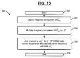
- FIG. 10is a flowchart illustrating steps for calculating the adapted carrier frequency estimate.
- the OFDM transmitter 30includes a data scrambler 32 that receives input bits and scrambles the bits to prevent long strings of 1's and 0's.
- An output of the data scrambler 32is input to a convolutional encoder 34 that adds redundant bits. For example, for each input bit the convolutional encoder 34 may generate two output bits in a rate 1 ⁇ 2 convolutional coder. Skilled artisans can appreciate that other code rates may be employed.
- An output of the convolutional encoder 34is input to an interleaver and symbol mapper 36 .
- An output of the interleaver and symbol mapper 36is input to a serial to parallel (S/P) converter 38 .
- Outputs of the S/P converter 38are input to an inverse fast Fourier transform (FFT) circuit 40 .
- Outputs of the inverse FFT circuit 40are input to a parallel to serial (P/S) converter 42 .
- An output of the P/S converter 42is input to a cyclic prefix adder 44 that adds guard interval bits.
- An output of the cyclic prefix adder 44is input to a waveform shaper 46 .
- An output of the waveform shaper 46is input to a digital to analog (D/A) converter 48 .
- An output of the D/A converter 48is input to a radio frequency (R/F) amplifier 50 that is connected to an antenna 52 .
- the OFDM transmitter 30complies with IEEE section 802.11(a).
- an OFDM receiver 60receives the RF signals that are generated by the OFDM transmitter 30 .
- the receiver 60includes antennas 62 - 1 and 62 - 2 .
- a switch 64selects one of the antennas 62 based upon the strength of the RF signal detected by the antenna 62 .
- An amplifier 66is connected to an output of the switch 64 .
- An analog to digital (A/D) converter 68is connected to an output of the amplifier 66 .
- An automatic gain control (AGC), antenna diversity and packet detection circuit 70is connected to an output of the A/D converter 68 . When the gain of the AGC decreases, a packet is detected.
- a symbol timing and carrier frequency offset circuit 74according to the present invention is connected to an output of the circuit 70 .
- the symbol timing and carrier frequency offset circuit 74identifies a carrier frequency offset ⁇ ⁇ , a starting time n g of a guard interval, and phase noise as will be described more fully below.
- the circuit 74typically multiples the samples by e ⁇ j ⁇ ⁇ n where n is a sample time index.
- a cyclic prefix remover 76is connected to an output of the symbol timing and carrier frequency offset circuit 74 .
- a S/P converter 78is connected to an output of the cyclic prefix remover 76 .
- a FFT circuit 80is connected to an output of the S/P converter 78 .
- a P/S converter 82is connected to an output of the FFT circuit 80 .
- a demap and deinterleave circuit 84is connected to an output of the P/S converter 82 .
- a channel estimator 86 that estimates multipathis connected to an output of the symbol timing and carrier frequency offset circuit 74 .
- a frequency equalizer (FEQ) 90is connected to an output of the channel estimator 86 .
- An output of the FEQ 90is input to the demap and deinterleave circuit 82 .
- An output of the demap and deinterleave circuit 82is input to a sample recovery clock 94 and to a Viterbi decoder 96 .
- An output of the sample recovery clock 94is input to the A/D converter 62 .
- An output of the Viterbi decoder 96is input to a descrambler 98 .
- FIG. 4a simplified functional block diagram of FIG. 3 is shown and includes a radio frequency (RF) amplifier 100 that amplifies the received RF signal.
- An output of the amplifier 100is input to a multiplier 102 having another input connected to a local oscillator (LO) 104 .
- An output of the multiplier 102is filtered by a filter 108 and input to an analog to digital (A/D) converter 110 having a sampling rate of 1/T s .
- the A/D converter 110generates samples r n .
- a typical value for 1/T sis 20 MHz, although other sampling frequencies may be used.
- the circuit 70brings the signal within a dynamic range of the OFDM receiver 60 . Antenna selection for receive diversity is also performed.
- q ncontains sign bits of real and imaginary components of the received signal r n . Quantization simplifies the hardware processing for symbol timing acquisition.
- P nrepresents a correlation between two adjacent short training symbols of q n .
- M nrepresents a filtered version of
- the filteris preferably a single pole filter with a pole ⁇ s .
- M nhas a plateau at 120 that results from the periodicity of the channel output due to the repetition of the short training symbols.
- the duration of the plateaudepends on the number of periods of the short training symbol that remain after antenna selection and AGC settling. Therefore, a center of the plateau is not the best symbol timing estimate.
- a falling edge of the plateauindicates that no more short training symbols are present and that M n includes samples from the guard interval 14 that precedes the long training symbols 16 . Therefore, the falling edge of the plateau provides an estimate of the symbol timing.
- a maximum value of M nis updated and stored as M n,max as time progresses.
- the complex number P n corresponding to M n,maxis denoted by P n,max , which is also updated and stored as time progresses.
- a local maximum value M n,localmaxis set equal to M n ⁇ 1 if the following conditions are met: M n ⁇ 1 ⁇ M n ⁇ 2 and M n ⁇ 1 >M n .
- the local maximum value M n,localmaxis updated and stored as time progresses.
- a time index n gis set to n ⁇ 1 if the following conditions are met: M n ⁇ 2 M n,localmax and M n ⁇ 1 ⁇ 2 M n,localmax .
- the index n gis used to determine the symbol timing.
- M nmust stay below ⁇ 1 M n,max for at least B consecutive samples.
- e ⁇ j ⁇ ⁇ nis applied to the received signal.
- a low pass filter (LPF) 150is connected to a sign-bit quantizer 152 .
- the sign-bit quantizer 152is connected to a buffer 154 and a multiplier 156 .
- An L-1 output of the buffer 154is connected to a conjugator 158 and a multiplier 160 .
- a 2L-1 output of the buffer 154is connected to a conjugator 162 , which has an output connected to the multiplier 160 .
- An output of the multiplier 160is connected to an inverting input of an adder 164 .
- An output of the multiplier 156is connected to a non-inverting input of the adder 164 .
- An output of the adder 164is input to an adder 170 .
- An output of the adder 170is equal to P n and is connected to a delay element 172 that is fed back to an input of the adder 170 .
- the output of the adder 174is also input to a metric calculator 174 .
- An output of the metric calculator 174is connected to a multiplier 176 .
- Another input of the multiplieris connected to a signal equal to 1 ⁇ s .
- An output of the multiplieris input to an adder 180 .
- An output of the adder 180is equal to M n and is connected to a delay element 182 , which has an output that is connected to a multiplier 184 .
- the multiplier 184has another input connected to ⁇ s .
- An output of the multiplier 184is connected to an input of the adder 180 .
- step 204M nmax , M nlocalmax , n 1 , n r , n s , n g , n max , and ctr are initialized.
- IEEE section 802.11(a)specifies that the transmit carrier frequency and sampling clock frequency are derived from the same reference oscillator.
- the normalized carrier frequency offset and the sampling frequency offsetare approximately equal. Since carrier frequency acquisition is usually easier than sampling period acquisition, sampling clock recovery is achieved using the estimate of the carrier frequency offset ⁇ ⁇ .
- the coarse frequency estimate ⁇ ⁇is used to correct all subsequent received samples.
- the coarse frequency estimate ⁇ ⁇is refined during the long training symbols specified in IEEE section 802.11(a).
- the value Nis the number of samples contained within each long training symbol 16 .
- ⁇ kare channel estimates for the OFDM subcarriers as a function of the subcarrier index k.
- the channel estimates ⁇ kare multiplied by a complex number ⁇ ML to compensate for common amplitude and phase error due to the residual frequency offsets and phase noise.
- the pilot tonesare used to derive a maximum likelihood estimate of ⁇ ML :
- the sampling clock frequencyis also adapted accordingly.
- n g ′is generated.
- the modified symbol timing estimate n g ′is equal to n g ⁇ n ⁇ where n ⁇ .
- the circuitincludes multipliers 256 - 1 , 256 - 2 , . . . , 256 - n that multiply ⁇ * k and P k , for k ⁇ K.
- Absolute value circuits 260 - 1 , 260 - 2 , . . . 260 - ncalculate an absolute value of ⁇ k .
- Outputs of the absolute value circuit 260are squared by multipliers 264 - 1 , 264 - 2 , . . . , 264 - n .
- Outputs of the multipliers 256are input to an adder 266 .
- Outputs of the multipliers 264are input to an adder 270 .
- An output of the adder 266is input to a numerator input of a divider 272 .
- An output of the adder 270is input to a denominator input of the divider 272 .
- An output of the divider 272 ⁇ MLis input to a multiplier 274 .
- Another input of the multiplier 274is connected to ⁇ k .
- An output of the multiplier 274generates ⁇ tilde over (H) ⁇ k .
- An output of the divider 272is input to an imaginary component circuit 280 that outputs an imaginary component of ⁇ ML .
- An output of the imaginary component circuit 280is input to a multiplier 284 .
- Another input of the multiplieris connected to the adaptation parameter ⁇ .
- An output of the multiplier 284is input to an adder 286 .
- Another input of the adderis connected to ⁇ ⁇ l-1 .
- An output of the adder 286generates ⁇ ⁇ l which is the adapted carrier frequency estimate.
- step 302control begins.
- step 304channel estimates ⁇ k are obtained.
- step 306frequency domain signals P k on the pilot tones are obtained after BPSK modulation is removed.
- step 308the conjugates of the channel estimates ⁇ k are multiplied by the frequency domain signals P k and summed for each value of K.
- step 310⁇ ML is computed by dividing the summed product generated in step 308 and divided by the sum for each value of k of the squared absolute values of ⁇ k .
- step 312the channel estimates ⁇ k are multiplied by ⁇ ML to obtain new channel estimates ⁇ tilde over (H) ⁇ k . Control ends in step 314 .
- step 322the imaginary component of ⁇ ML is generated.
- step 326the imaginary component of ⁇ ML is multiplied by the adaptation parameter ⁇ .
- step 328the product of step 326 is added to ⁇ ⁇ l-1 (the l-1th carrier frequency offset estimate) to generate ⁇ ⁇ l .
- step 330the product of step 326 is added to ⁇ ⁇ l-1 (the l-1th carrier frequency offset estimate) to generate ⁇ ⁇ l .
- a typical value for L16, although other values may be used.
- P nrepresents a correlation between two adjacent short training symbols.
- R nrepresents an average received power in a short training symbol.
- M nrepresents a normalized correlation between two adjacent short training symbols.
- M nexhibits the plateau at 120 due to the repetition of the short training symbol.
- M nis a maximum value as a sample window moves across the short training symbols 12 after packet detection and AGC settling.
- P ncorrelates received signals for two adjacent short training samples.
- the sampling windowhas a duration of 2L, although other durations are contemplated.
- the duration of the plateau 120depends upon the number of periods of the short training symbol that remain after antenna selection and AGC settling is complete. Therefore, the center of the plateau 120 of M n is not usually the best symbol timing estimate.
- the right edge of the plateau 120indicates that no more short training symbols are present. Samples that occur after the right edge of the plateau include samples from the guard interval 14 that precedes the long training symbols 16 . Therefore, the right edge of the plateau 120 provides a good estimate of the symbol timing.
- M nis computed.
- M maxis the maximum of M n and n max corresponds to a time index at which M max occurs.
- Points n 1 and n rare left and right edges of the plateau 120 , respectively.
- the points n 1 and n rare identified such that M n1 ⁇ M nr ⁇ 1 M max and n 1 ⁇ n max ⁇ n r .
- n 1 and n rare the points preceding and following the maximum of M n that are equal to a threshold ⁇ 1 multiplied by M max .
- a typical value for ⁇ 1is 0.7.
- the estimate of the carrier frequency offset ⁇ fmay be refined using a correlation of the two long training symbols after the sample timing is determined as will be described below.
- Kis the number of terms in the estimate of the mean absolute difference.
- a typical value for Kis (n r ⁇ n 1 )/2.
- the sample index n g at the beginning of the guard interval 14 preceding the long training symbols 16is estimated by detecting the right or following edge of the plateau of M n .
- n gsatisfies the following conditions: n g >n c M n g ⁇ M n g ⁇ 1
- > ⁇ 2 D K n g ′n g ⁇ n ⁇ A typical value for ⁇ 2 is 10.
- n g ′is generated.
- the modified symbol timing estimate n g ′is equal to n g ⁇ n ⁇ where n ⁇ is a small number that is less than the number of samples in the guard interval for a data symbol.
- the number of samples in the guard interval for a data symbolis L, which is the number of samples in a short training symbol.
- n ⁇is L/4.
- the identification of the precise time that M n decreases from the plateau 120may vary somewhat.
- the modified symbol timing estimate n g ′provides additional tolerance. With the modified symbol timing estimate n g ′, a sampling window begins earlier in the guard interval 14 .
- IEEE section 802.11(a)specifies that the transmit frequency and sample clock frequency are derived from the same reference oscillator. Therefore, the normalized carrier frequency offset and sampling period offset are approximately equal. Since carrier frequency acquisition is more simple than sampling period acquisition, sampling clock recovery is achieved using the estimate of the carrier frequency offset.
- the initial carrier frequency offset estimate ⁇ f 0is obtained during the short timing symbols 12 in the preamble 10 of each packet as previously described above.
- ⁇ na residual carrier frequency offset
- ⁇is a loop parameter. This method is currently being used with a zero order hold after IFFT in the transmitter 30 (to model D/A).
Landscapes
- Engineering & Computer Science (AREA)
- Computer Networks & Wireless Communication (AREA)
- Signal Processing (AREA)
- Power Engineering (AREA)
- Digital Transmission Methods That Use Modulated Carrier Waves (AREA)
- Synchronisation In Digital Transmission Systems (AREA)
- Mobile Radio Communication Systems (AREA)
Abstract
Description
qn=sgn[

Mn=αsMn−1+(1−αs)(|
ωΔ=tan−1[ℑ(Pn,max)/
A coarse frequency correction e−jωΔnis applied to the received signal. The symbol timing is then estimated by ng′=ng−nΔ. A typical value for nΔ is nΔ=32.
ωΔ,fine=tan−1[ℑ(CL)/
where
The sampling clock is also updated accordingly.
The new channel estimates are then {tilde over (H)}k=ĈMLĤk. These updated channel estimates are used in the frequency equalizer (FEQ) for data detection.
ωΔl=ωΔl-1+βℑ(ĈML)
where β is an adaptation parameter and the
Mn=|Pn|2/Rn2
α=tan−1[ℑ(Pnc)/
Δf=α/(2πTshort) which is valid if |Δf|<1/(2Tshort).
For example, |Δf|<1/(2Tshort)=625 kHz for Tshort=0.8 μs. The estimate of the carrier frequency offset Δf may be refined using a correlation of the two long training symbols after the sample timing is determined as will be described below.
Where K is the number of terms in the estimate of the mean absolute difference. A typical value for K is (nr−n1)/2. The sample index ngat the beginning of the
ng>nc
Mn
|Mn
ng′=ng−nΔ
A typical value for τ2is 10.
T0=Torgi(1−(Δf0/fnominal)).
Where fnominalis the nominal carrier frequency. The estimate of the carrier frequency offset during the
T1=T0(1−(ε1/fnominal))
Δfn=Δfn−1+βεn
Tn=Tn−1(1−(βεn/fnominal))
Where β is a loop parameter. This method is currently being used with a zero order hold after IFFT in the transmitter30 (to model D/A).
Claims (84)
Priority Applications (5)
| Application Number | Priority Date | Filing Date | Title |
|---|---|---|---|
| US10/067,556US7218691B1 (en) | 2001-03-05 | 2002-02-04 | Method and apparatus for estimation of orthogonal frequency division multiplexing symbol timing and carrier frequency offset |
| US11/801,032US7532693B1 (en) | 2001-03-05 | 2007-05-08 | Method and apparatus for acquistion and tracking of orthogonal frequency division multiplexing symbol timing, carrier frequency offset and phase noise |
| US12/393,547US8300743B1 (en) | 2001-03-05 | 2009-02-26 | Method and apparatus for acquisition and tracking of orthogonal frequency division multiplexing symbol timing, carrier frequency offset and phase noise |
| US13/660,580US8619922B1 (en) | 2002-02-04 | 2012-10-25 | Method and apparatus for acquisition and tracking of orthogonal frequency division multiplexing symbol timing, carrier frequency offset and phase noise |
| US14/143,722US8929487B1 (en) | 2001-03-05 | 2013-12-30 | Channel estimator for updating channel estimates and carrier frequency offsets |
Applications Claiming Priority (2)
| Application Number | Priority Date | Filing Date | Title |
|---|---|---|---|
| US27348701P | 2001-03-05 | 2001-03-05 | |
| US10/067,556US7218691B1 (en) | 2001-03-05 | 2002-02-04 | Method and apparatus for estimation of orthogonal frequency division multiplexing symbol timing and carrier frequency offset |
Related Child Applications (1)
| Application Number | Title | Priority Date | Filing Date |
|---|---|---|---|
| US11/801,032DivisionUS7532693B1 (en) | 2001-03-05 | 2007-05-08 | Method and apparatus for acquistion and tracking of orthogonal frequency division multiplexing symbol timing, carrier frequency offset and phase noise |
Publications (1)
| Publication Number | Publication Date |
|---|---|
| US7218691B1true US7218691B1 (en) | 2007-05-15 |
Family
ID=38015795
Family Applications (3)
| Application Number | Title | Priority Date | Filing Date |
|---|---|---|---|
| US10/067,556Expired - LifetimeUS7218691B1 (en) | 2001-03-05 | 2002-02-04 | Method and apparatus for estimation of orthogonal frequency division multiplexing symbol timing and carrier frequency offset |
| US11/801,032Expired - LifetimeUS7532693B1 (en) | 2001-03-05 | 2007-05-08 | Method and apparatus for acquistion and tracking of orthogonal frequency division multiplexing symbol timing, carrier frequency offset and phase noise |
| US12/393,547Expired - LifetimeUS8300743B1 (en) | 2001-03-05 | 2009-02-26 | Method and apparatus for acquisition and tracking of orthogonal frequency division multiplexing symbol timing, carrier frequency offset and phase noise |
Family Applications After (2)
| Application Number | Title | Priority Date | Filing Date |
|---|---|---|---|
| US11/801,032Expired - LifetimeUS7532693B1 (en) | 2001-03-05 | 2007-05-08 | Method and apparatus for acquistion and tracking of orthogonal frequency division multiplexing symbol timing, carrier frequency offset and phase noise |
| US12/393,547Expired - LifetimeUS8300743B1 (en) | 2001-03-05 | 2009-02-26 | Method and apparatus for acquisition and tracking of orthogonal frequency division multiplexing symbol timing, carrier frequency offset and phase noise |
Country Status (1)
| Country | Link |
|---|---|
| US (3) | US7218691B1 (en) |
Cited By (29)
| Publication number | Priority date | Publication date | Assignee | Title |
|---|---|---|---|---|
| US20050059366A1 (en)* | 2003-09-16 | 2005-03-17 | Atheros Communications, Inc. | Spur mitigation techniques |
| US20050063298A1 (en)* | 2003-09-02 | 2005-03-24 | Qualcomm Incorporated | Synchronization in a broadcast OFDM system using time division multiplexed pilots |
| US20050129136A1 (en)* | 2003-11-11 | 2005-06-16 | Ntt Docomo, Inc. | OFDM receiver |
| US20050163263A1 (en)* | 2004-01-28 | 2005-07-28 | Gupta Alok K. | Systems and methods for frequency acquisition in a wireless communication network |
| US20050163262A1 (en)* | 2004-01-28 | 2005-07-28 | Qualcomm Incorporated | Frame synchronization and initial symbol timing acquisition system and method |
| US20060018390A1 (en)* | 2004-07-20 | 2006-01-26 | Chun-Ming Cho | Method and apparatus of detecting isi/icsi in an ofdm system |
| US20060018391A1 (en)* | 2004-07-20 | 2006-01-26 | Chun-Ming Cho | Method and apparatus of detecting isi/icsi in an ofdm system |
| US20060062335A1 (en)* | 2004-09-17 | 2006-03-23 | Samsung Electronics Co., Ltd. | Sync extraction apparatus in communication system and method thereof |
| US20060104335A1 (en)* | 2004-11-03 | 2006-05-18 | Broadcom Corporation | Low-rate long-range mode for OFDM wireless LAN |
| US20070147552A1 (en)* | 2005-12-16 | 2007-06-28 | Interdigital Technology Corporation | Method and apparatus for detecting transmission of a packet in a wireless communication system |
| US20080225985A1 (en)* | 2007-03-13 | 2008-09-18 | Wu Shiquan Robert | Method and Apparatus for Enhancing GSM System Capacity |
| US20080291817A1 (en)* | 2004-01-28 | 2008-11-27 | Qualcomm Incorporated | Timing estimation in an ofdm receiver |
| US20090074045A1 (en)* | 2007-09-13 | 2009-03-19 | Beceem Communications, Inc. | Estimating frequency offset at a subscriber station receiver |
| US20090116545A1 (en)* | 2003-07-08 | 2009-05-07 | Conexant Systems, Inc. | Adaptive Frequency Equalizer |
| US20090141832A1 (en)* | 2007-11-30 | 2009-06-04 | Beceem Communications Inc. | Method for estimating frequency offset at a subscriber station receiver in a multi-carrier system |
| US20090147900A1 (en)* | 2007-12-11 | 2009-06-11 | Industrial Technology Research Institute | Method and device for detecting a synchronization signal in a communication system |
| US20090190675A1 (en)* | 2004-08-31 | 2009-07-30 | Qualcomm Incorporated | Synchronization in a broadcast ofdm system using time division multiplexed pilots |
| US20090274250A1 (en)* | 2006-06-20 | 2009-11-05 | Nxp B.V. | Method and apparatus for estimating carrier frequency offset |
| US20100027691A1 (en)* | 2008-08-01 | 2010-02-04 | Mark Kent | Method and system for an ofdm joint timing and frequency tracking system |
| US20100027499A1 (en)* | 2008-08-01 | 2010-02-04 | Mark Kent | Method and system for a reference signal (rs) timing loop for ofdm symbol synchronization and tracking |
| KR100982780B1 (en) | 2008-12-05 | 2010-09-20 | 경희대학교 산학협력단 | Carrier Frequency Offset Estimation Method in ODFM-based WLAN System |
| CN101222241B (en)* | 2008-01-02 | 2011-05-11 | 中兴通讯股份有限公司 | Method for reducing prefix disturbance in IEEE802.16e system |
| US8300743B1 (en) | 2001-03-05 | 2012-10-30 | Marvell International Ltd. | Method and apparatus for acquisition and tracking of orthogonal frequency division multiplexing symbol timing, carrier frequency offset and phase noise |
| US8619922B1 (en) | 2002-02-04 | 2013-12-31 | Marvell International Ltd. | Method and apparatus for acquisition and tracking of orthogonal frequency division multiplexing symbol timing, carrier frequency offset and phase noise |
| US9288764B1 (en) | 2008-12-31 | 2016-03-15 | Marvell International Ltd. | Discovery-phase power conservation |
| US10659817B2 (en)* | 2013-07-15 | 2020-05-19 | Hfi Innovation Inc. | Method of sample adaptive offset processing for video coding |
| US20220209808A1 (en)* | 2020-12-30 | 2022-06-30 | Silicon Laboratories Inc. | Apparatus for Receiver with Carrier Frequency Offset Correction Using Frequency Information and Associated Methods |
| US11770287B2 (en) | 2020-12-30 | 2023-09-26 | Silicon Laboratories Inc. | Apparatus for receiver with carrier frequency offset correction using phase and frequency information and associated methods |
| CN118748635A (en)* | 2024-07-25 | 2024-10-08 | 苏州赛迈测控技术有限公司 | A frequency deviation estimation method and system for WIFI6 system |
Families Citing this family (24)
| Publication number | Priority date | Publication date | Assignee | Title |
|---|---|---|---|---|
| IL154695A0 (en)* | 2000-08-30 | 2003-09-17 | Tiaris Inc | A home network system and method |
| US8724485B2 (en)* | 2000-08-30 | 2014-05-13 | Broadcom Corporation | Home network system and method |
| US9094226B2 (en)* | 2000-08-30 | 2015-07-28 | Broadcom Corporation | Home network system and method |
| US20040177381A1 (en)* | 2002-09-05 | 2004-09-09 | Tiaris, Inc. | Home network system which supports legacy digital set top box devices |
| US8223623B2 (en)* | 2005-03-28 | 2012-07-17 | Qualcomm Incorporated | Timing and frequency acquisition for OFDM systems |
| US7782850B2 (en) | 2006-11-20 | 2010-08-24 | Broadcom Corporation | MAC to PHY interface apparatus and methods for transmission of packets through a communications network |
| US8090043B2 (en) | 2006-11-20 | 2012-01-03 | Broadcom Corporation | Apparatus and methods for compensating for signal imbalance in a receiver |
| US7742495B2 (en) | 2006-11-20 | 2010-06-22 | Broadcom Corporation | System and method for retransmitting packets over a network of communication channels |
| US8345553B2 (en) | 2007-05-31 | 2013-01-01 | Broadcom Corporation | Apparatus and methods for reduction of transmission delay in a communication network |
| US8098770B2 (en)* | 2008-05-06 | 2012-01-17 | Broadcom Corporation | Unbiased signal-to-noise ratio estimation for receiver having channel estimation error |
| US9112717B2 (en) | 2008-07-31 | 2015-08-18 | Broadcom Corporation | Systems and methods for providing a MoCA power management strategy |
| US8254413B2 (en) | 2008-12-22 | 2012-08-28 | Broadcom Corporation | Systems and methods for physical layer (“PHY”) concatenation in a multimedia over coax alliance network |
| US8238227B2 (en)* | 2008-12-22 | 2012-08-07 | Broadcom Corporation | Systems and methods for providing a MoCA improved performance for short burst packets |
| US8213309B2 (en)* | 2008-12-22 | 2012-07-03 | Broadcom Corporation | Systems and methods for reducing latency and reservation request overhead in a communications network |
| US20100238932A1 (en)* | 2009-03-19 | 2010-09-23 | Broadcom Corporation | Method and apparatus for enhanced packet aggregation |
| US8553547B2 (en) | 2009-03-30 | 2013-10-08 | Broadcom Corporation | Systems and methods for retransmitting packets over a network of communication channels |
| US20100254278A1 (en)* | 2009-04-07 | 2010-10-07 | Broadcom Corporation | Assessment in an information network |
| US8730798B2 (en)* | 2009-05-05 | 2014-05-20 | Broadcom Corporation | Transmitter channel throughput in an information network |
| US8867355B2 (en)* | 2009-07-14 | 2014-10-21 | Broadcom Corporation | MoCA multicast handling |
| US8942250B2 (en) | 2009-10-07 | 2015-01-27 | Broadcom Corporation | Systems and methods for providing service (“SRV”) node selection |
| US8731029B1 (en) | 2010-01-12 | 2014-05-20 | Marvell International Ltd. | Frequency offset acquisition for wireless communications |
| US8611327B2 (en) | 2010-02-22 | 2013-12-17 | Broadcom Corporation | Method and apparatus for policing a QoS flow in a MoCA 2.0 network |
| US8514860B2 (en) | 2010-02-23 | 2013-08-20 | Broadcom Corporation | Systems and methods for implementing a high throughput mode for a MoCA device |
| WO2014171341A1 (en)* | 2013-04-15 | 2014-10-23 | ソニー株式会社 | Reception apparatus, reception method, and program |
Citations (42)
| Publication number | Priority date | Publication date | Assignee | Title |
|---|---|---|---|---|
| US4550414A (en) | 1983-04-12 | 1985-10-29 | Charles Stark Draper Laboratory, Inc. | Spread spectrum adaptive code tracker |
| US5053982A (en) | 1989-02-14 | 1991-10-01 | Proxim, Inc. | Variable modulus digital synthesizer |
| US5077753A (en) | 1990-04-09 | 1991-12-31 | Proxim, Inc. | Radio communication system using spread spectrum techniques |
| US5111478A (en) | 1991-01-31 | 1992-05-05 | Motorola, Inc. | Method and apparatus for providing signal synchronization in a spread spectrum communication system |
| US5231634A (en) | 1991-12-18 | 1993-07-27 | Proxim, Inc. | Medium access protocol for wireless lans |
| CA2064975A1 (en) | 1992-03-27 | 1993-09-28 | Michel T. Fattouche | Method and apparatus for multiple access between transceivers in wireless communications using ofdm spread spectrum |
| US5282222A (en) | 1992-03-31 | 1994-01-25 | Michel Fattouche | Method and apparatus for multiple access between transceivers in wireless communications using OFDM spread spectrum |
| US5311544A (en) | 1992-11-19 | 1994-05-10 | Samsung Electronics Co., Ltd. | Receiver of a direct sequence spread spectrum system |
| US5555268A (en) | 1994-01-24 | 1996-09-10 | Fattouche; Michel | Multicode direct sequence spread spectrum |
| US5602835A (en) | 1993-11-16 | 1997-02-11 | Kabushiki Kaisha Toshiba | OFDM synchronization demodulation circuit |
| US5608764A (en) | 1993-11-12 | 1997-03-04 | Kabushiki Kaisha Toshiba | OFDM synchronization demodulation circuit |
| US5625573A (en)* | 1995-03-01 | 1997-04-29 | Hughes Electronics | Fast acquisition of GMSK-modulated signal for CDPD applications |
| US5694389A (en)* | 1995-02-24 | 1997-12-02 | Kabushiki Kaisha Toshiba | OFDM transmission/reception system and transmitting/receiving apparatus |
| US5726973A (en) | 1994-01-18 | 1998-03-10 | Telia Ab | Method and arrangement for synchronization in OFDM modulation |
| US5732113A (en)* | 1996-06-20 | 1998-03-24 | Stanford University | Timing and frequency synchronization of OFDM signals |
| US5802117A (en) | 1996-02-08 | 1998-09-01 | Philips Electronics North America Corporation | Method and apparatus for joint frequency offset and timing estimation of a multicarrier modulation system |
| US5809060A (en) | 1994-02-17 | 1998-09-15 | Micrilor, Inc. | High-data-rate wireless local-area network |
| US5889759A (en) | 1996-08-12 | 1999-03-30 | Telecommunications Research Laboratories | OFDM timing and frequency recovery system |
| US5909462A (en)* | 1996-12-31 | 1999-06-01 | Lucent Technologies Inc. | System and method for improved spread spectrum signal detection |
| US5953311A (en) | 1997-02-18 | 1999-09-14 | Discovision Associates | Timing synchronization in a receiver employing orthogonal frequency division multiplexing |
| US5991289A (en) | 1997-08-05 | 1999-11-23 | Industrial Technology Research Institute | Synchronization method and apparatus for guard interval-based OFDM signals |
| US6035003A (en) | 1996-11-29 | 2000-03-07 | Daewoo Electronics Co., Ltd. | Apparatus for correcting frequency offset in OFDM receiving system |
| US6058101A (en) | 1997-06-11 | 2000-05-02 | Industrial Technology Research Institute | Synchronization method and system for a digital receiver |
| US6075812A (en) | 1994-02-17 | 2000-06-13 | Micrilor, Inc. | High-data-rate wireless local-area network |
| US6074086A (en) | 1999-04-26 | 2000-06-13 | Intellon Corporation | Synchronization of OFDM signals with improved windowing |
| US6091702A (en) | 1996-07-31 | 2000-07-18 | Victor Company Of Japan, Ltd. | Method and apparatus for symbol synchronization in orthogonal frequency division multiplexing systems |
| US6111919A (en) | 1999-01-20 | 2000-08-29 | Intellon Corporation | Synchronization of OFDM signals |
| US6125124A (en) | 1996-09-16 | 2000-09-26 | Nokia Technology Gmbh | Synchronization and sampling frequency in an apparatus receiving OFDM modulated transmissions |
| US6160821A (en) | 1997-11-05 | 2000-12-12 | Sony International (Europe) Gmbh | Synchronization of digital communication systems |
| US6169751B1 (en) | 1997-03-10 | 2001-01-02 | Matsushita Electric Industrial Co., Ltd. | OFDM receiving apparatus |
| US6172993B1 (en) | 1996-12-28 | 2001-01-09 | Daewoo Electronics Co., Ltd. | Frame synchronization method and apparatus for use in digital communication system utilizing OFDM method |
| US6414936B1 (en)* | 1998-09-07 | 2002-07-02 | Korea Electronics Technology Institute | Method of estimating carrier frequency offset in an orthogonal frequency division multiplexing system |
| US20020126618A1 (en)* | 2000-12-29 | 2002-09-12 | Kim Dong Kyu | Timing and frequency offset estimation scheme for OFDM systems by using an analytic tone |
| US20030058966A1 (en)* | 2001-09-24 | 2003-03-27 | Gilbert Jeffrey M. | Fine frequency offset estimation and calculation and use to improve communication system performance |
| US20030112743A1 (en)* | 2001-11-16 | 2003-06-19 | Charles You | Timing synchronization for OFDM-based wireless networks |
| US20030215022A1 (en)* | 2001-08-15 | 2003-11-20 | Kuo-Hui Li | OFDM detection apparatus and method for networking devices |
| US6658063B1 (en)* | 1999-07-19 | 2003-12-02 | Nippon Telegraph And Telephone Corporation | OFDM packet communication receiver system |
| US6711221B1 (en)* | 2000-02-16 | 2004-03-23 | Thomson Licensing S.A. | Sampling offset correction in an orthogonal frequency division multiplexing system |
| US6771591B1 (en)* | 2000-07-31 | 2004-08-03 | Thomson Licensing S.A. | Method and system for processing orthogonal frequency division multiplexed signals |
| US20040202234A1 (en)* | 2003-04-11 | 2004-10-14 | Agency For Science, Technology And Research | Low-complexity and fast frequency offset estimation for OFDM signals |
| US6862297B1 (en)* | 1999-12-21 | 2005-03-01 | Cisco Technology, Inc. | Wide range frequency offset estimation in OFDM systems |
| US6874096B1 (en)* | 2000-06-23 | 2005-03-29 | 2Wire, Inc. | Apparatus and method for detecting packet arrival time |
Family Cites Families (8)
| Publication number | Priority date | Publication date | Assignee | Title |
|---|---|---|---|---|
| US4941155A (en)* | 1989-11-16 | 1990-07-10 | Bell Communications Research, Inc. | Method and circuitry for symbol timing and frequency offset estimation in time division multiple access radio systems |
| CA2365129C (en)* | 1999-12-28 | 2007-12-18 | Ntt Docomo, Inc. | Path search method, channel estimation method and communication device |
| US6754170B1 (en)* | 2000-09-29 | 2004-06-22 | Symbol Technologies, Inc. | Timing synchronization in OFDM communications receivers |
| US7106709B2 (en)* | 2000-11-29 | 2006-09-12 | Telefonaktiebologet Lm Ericsson (Publ) | Timing drift compensation in wireless packet-based systems |
| US20020065047A1 (en)* | 2000-11-30 | 2002-05-30 | Moose Paul H. | Synchronization, channel estimation and pilot tone tracking system |
| US7218691B1 (en) | 2001-03-05 | 2007-05-15 | Marvell International Ltd. | Method and apparatus for estimation of orthogonal frequency division multiplexing symbol timing and carrier frequency offset |
| US7415059B2 (en)* | 2002-11-14 | 2008-08-19 | Edgewater Computer Systems, Inc. | Method and system for fast timing recovery for preamble based transmission systems |
| US7280621B1 (en)* | 2003-03-31 | 2007-10-09 | 3Com Corporation | Preamble detector method and device for OFDM systems |
- 2002
- 2002-02-04USUS10/067,556patent/US7218691B1/ennot_activeExpired - Lifetime
- 2007
- 2007-05-08USUS11/801,032patent/US7532693B1/ennot_activeExpired - Lifetime
- 2009
- 2009-02-26USUS12/393,547patent/US8300743B1/ennot_activeExpired - Lifetime
Patent Citations (44)
| Publication number | Priority date | Publication date | Assignee | Title |
|---|---|---|---|---|
| US4550414A (en) | 1983-04-12 | 1985-10-29 | Charles Stark Draper Laboratory, Inc. | Spread spectrum adaptive code tracker |
| US5053982A (en) | 1989-02-14 | 1991-10-01 | Proxim, Inc. | Variable modulus digital synthesizer |
| US5077753A (en) | 1990-04-09 | 1991-12-31 | Proxim, Inc. | Radio communication system using spread spectrum techniques |
| US5111478A (en) | 1991-01-31 | 1992-05-05 | Motorola, Inc. | Method and apparatus for providing signal synchronization in a spread spectrum communication system |
| US5231634A (en) | 1991-12-18 | 1993-07-27 | Proxim, Inc. | Medium access protocol for wireless lans |
| US5231634B1 (en) | 1991-12-18 | 1996-04-02 | Proxim Inc | Medium access protocol for wireless lans |
| CA2064975A1 (en) | 1992-03-27 | 1993-09-28 | Michel T. Fattouche | Method and apparatus for multiple access between transceivers in wireless communications using ofdm spread spectrum |
| US5282222A (en) | 1992-03-31 | 1994-01-25 | Michel Fattouche | Method and apparatus for multiple access between transceivers in wireless communications using OFDM spread spectrum |
| US5311544A (en) | 1992-11-19 | 1994-05-10 | Samsung Electronics Co., Ltd. | Receiver of a direct sequence spread spectrum system |
| US5608764A (en) | 1993-11-12 | 1997-03-04 | Kabushiki Kaisha Toshiba | OFDM synchronization demodulation circuit |
| US5602835A (en) | 1993-11-16 | 1997-02-11 | Kabushiki Kaisha Toshiba | OFDM synchronization demodulation circuit |
| US5726973A (en) | 1994-01-18 | 1998-03-10 | Telia Ab | Method and arrangement for synchronization in OFDM modulation |
| US5555268A (en) | 1994-01-24 | 1996-09-10 | Fattouche; Michel | Multicode direct sequence spread spectrum |
| US5809060A (en) | 1994-02-17 | 1998-09-15 | Micrilor, Inc. | High-data-rate wireless local-area network |
| US6075812A (en) | 1994-02-17 | 2000-06-13 | Micrilor, Inc. | High-data-rate wireless local-area network |
| US5694389A (en)* | 1995-02-24 | 1997-12-02 | Kabushiki Kaisha Toshiba | OFDM transmission/reception system and transmitting/receiving apparatus |
| US5625573A (en)* | 1995-03-01 | 1997-04-29 | Hughes Electronics | Fast acquisition of GMSK-modulated signal for CDPD applications |
| US5802117A (en) | 1996-02-08 | 1998-09-01 | Philips Electronics North America Corporation | Method and apparatus for joint frequency offset and timing estimation of a multicarrier modulation system |
| US5732113A (en)* | 1996-06-20 | 1998-03-24 | Stanford University | Timing and frequency synchronization of OFDM signals |
| US6091702A (en) | 1996-07-31 | 2000-07-18 | Victor Company Of Japan, Ltd. | Method and apparatus for symbol synchronization in orthogonal frequency division multiplexing systems |
| US6021110A (en) | 1996-08-12 | 2000-02-01 | Telecommunications Research Laboratories | OFDM timing and frequency recovery system |
| US5889759A (en) | 1996-08-12 | 1999-03-30 | Telecommunications Research Laboratories | OFDM timing and frequency recovery system |
| US6125124A (en) | 1996-09-16 | 2000-09-26 | Nokia Technology Gmbh | Synchronization and sampling frequency in an apparatus receiving OFDM modulated transmissions |
| US6035003A (en) | 1996-11-29 | 2000-03-07 | Daewoo Electronics Co., Ltd. | Apparatus for correcting frequency offset in OFDM receiving system |
| US6172993B1 (en) | 1996-12-28 | 2001-01-09 | Daewoo Electronics Co., Ltd. | Frame synchronization method and apparatus for use in digital communication system utilizing OFDM method |
| US5909462A (en)* | 1996-12-31 | 1999-06-01 | Lucent Technologies Inc. | System and method for improved spread spectrum signal detection |
| US5953311A (en) | 1997-02-18 | 1999-09-14 | Discovision Associates | Timing synchronization in a receiver employing orthogonal frequency division multiplexing |
| US6169751B1 (en) | 1997-03-10 | 2001-01-02 | Matsushita Electric Industrial Co., Ltd. | OFDM receiving apparatus |
| US6058101A (en) | 1997-06-11 | 2000-05-02 | Industrial Technology Research Institute | Synchronization method and system for a digital receiver |
| US5991289A (en) | 1997-08-05 | 1999-11-23 | Industrial Technology Research Institute | Synchronization method and apparatus for guard interval-based OFDM signals |
| US6160821A (en) | 1997-11-05 | 2000-12-12 | Sony International (Europe) Gmbh | Synchronization of digital communication systems |
| US6414936B1 (en)* | 1998-09-07 | 2002-07-02 | Korea Electronics Technology Institute | Method of estimating carrier frequency offset in an orthogonal frequency division multiplexing system |
| US6111919A (en) | 1999-01-20 | 2000-08-29 | Intellon Corporation | Synchronization of OFDM signals |
| US6074086A (en) | 1999-04-26 | 2000-06-13 | Intellon Corporation | Synchronization of OFDM signals with improved windowing |
| US6658063B1 (en)* | 1999-07-19 | 2003-12-02 | Nippon Telegraph And Telephone Corporation | OFDM packet communication receiver system |
| US6862297B1 (en)* | 1999-12-21 | 2005-03-01 | Cisco Technology, Inc. | Wide range frequency offset estimation in OFDM systems |
| US6711221B1 (en)* | 2000-02-16 | 2004-03-23 | Thomson Licensing S.A. | Sampling offset correction in an orthogonal frequency division multiplexing system |
| US6874096B1 (en)* | 2000-06-23 | 2005-03-29 | 2Wire, Inc. | Apparatus and method for detecting packet arrival time |
| US6771591B1 (en)* | 2000-07-31 | 2004-08-03 | Thomson Licensing S.A. | Method and system for processing orthogonal frequency division multiplexed signals |
| US20020126618A1 (en)* | 2000-12-29 | 2002-09-12 | Kim Dong Kyu | Timing and frequency offset estimation scheme for OFDM systems by using an analytic tone |
| US20030215022A1 (en)* | 2001-08-15 | 2003-11-20 | Kuo-Hui Li | OFDM detection apparatus and method for networking devices |
| US20030058966A1 (en)* | 2001-09-24 | 2003-03-27 | Gilbert Jeffrey M. | Fine frequency offset estimation and calculation and use to improve communication system performance |
| US20030112743A1 (en)* | 2001-11-16 | 2003-06-19 | Charles You | Timing synchronization for OFDM-based wireless networks |
| US20040202234A1 (en)* | 2003-04-11 | 2004-10-14 | Agency For Science, Technology And Research | Low-complexity and fast frequency offset estimation for OFDM signals |
Non-Patent Citations (6)
| Title |
|---|
| "Wireless LAN Standard" IEEE Std 802.11a-1999. |
| A high performance frequency and timing synchronization technique for OFDM□□Mochizuki, N. et al; Global Telecommunications Conference, 1998. GLOBECOM 98. The Bridge to Global Integration. IEEE vol. 6, Nov. 8-12, 1998 pp. 3443-3448 vol. 6.* |
| A novel method for blind frequency offset correction in an OFDM system□□Visser, M.A. et al; Personal, Indoor and Mobile Radio Communications, 1998. The Ninth IEEE International Symposium on□□vol. 2, Sep. 8-11, 1998 pp. 816-820.* |
| A synchronization scheme for multi-carrier CDMA systems□□Seunghyeon Nahm; Wanyang Sung; Communications, 1998. ICC 98. Conference Record. 1998 IEEE International Conference on vol. 3, Jun. 7-11, 1998 pp. 1330-1334 vol. 3.* |
| Analysis of coarse frequency synchronisation for HIPERLAN type-2□□Platbrood, F.; Rievers, S.; Farserotu, J.; Vehicular Technology Conference, 1999. VTC 1999-Fall. IEEE VTS 50th□□vol. 2, Sep. 19-22, 1999 pp. 688-692 vol. 2 □□.* |
| Schmidl, Timothy M. "Robust Frequency and Timing Synchronization for OFDM" IEEE Transactions on Communications, vol. 45, No. 12, Dec. 1997. |
Cited By (57)
| Publication number | Priority date | Publication date | Assignee | Title |
|---|---|---|---|---|
| US8929487B1 (en) | 2001-03-05 | 2015-01-06 | Marvell International Ltd. | Channel estimator for updating channel estimates and carrier frequency offsets |
| US8300743B1 (en) | 2001-03-05 | 2012-10-30 | Marvell International Ltd. | Method and apparatus for acquisition and tracking of orthogonal frequency division multiplexing symbol timing, carrier frequency offset and phase noise |
| US8619922B1 (en) | 2002-02-04 | 2013-12-31 | Marvell International Ltd. | Method and apparatus for acquisition and tracking of orthogonal frequency division multiplexing symbol timing, carrier frequency offset and phase noise |
| US7957463B2 (en)* | 2003-07-08 | 2011-06-07 | Xocyst Transfer Ag L.L.C. | Adaptive frequency equalizer |
| US20090116545A1 (en)* | 2003-07-08 | 2009-05-07 | Conexant Systems, Inc. | Adaptive Frequency Equalizer |
| US20050063298A1 (en)* | 2003-09-02 | 2005-03-24 | Qualcomm Incorporated | Synchronization in a broadcast OFDM system using time division multiplexed pilots |
| US8184754B1 (en) | 2003-09-16 | 2012-05-22 | Qualcomm Atheros, Inc. | Spur mitigation techniques |
| US7835456B2 (en)* | 2003-09-16 | 2010-11-16 | Atheros Communications, Inc. | Spur mitigation techniques |
| US20050059366A1 (en)* | 2003-09-16 | 2005-03-17 | Atheros Communications, Inc. | Spur mitigation techniques |
| US20080123761A1 (en)* | 2003-09-16 | 2008-05-29 | Won-Joon Choi | Spur Mitigation Techniques |
| US20050129136A1 (en)* | 2003-11-11 | 2005-06-16 | Ntt Docomo, Inc. | OFDM receiver |
| US7415085B2 (en)* | 2003-11-11 | 2008-08-19 | Ntt Docomo, Inc. | OFDM receiver |
| US8433005B2 (en) | 2004-01-28 | 2013-04-30 | Qualcomm Incorporated | Frame synchronization and initial symbol timing acquisition system and method |
| US20080291817A1 (en)* | 2004-01-28 | 2008-11-27 | Qualcomm Incorporated | Timing estimation in an ofdm receiver |
| US20050163262A1 (en)* | 2004-01-28 | 2005-07-28 | Qualcomm Incorporated | Frame synchronization and initial symbol timing acquisition system and method |
| US20050163263A1 (en)* | 2004-01-28 | 2005-07-28 | Gupta Alok K. | Systems and methods for frequency acquisition in a wireless communication network |
| US8724447B2 (en) | 2004-01-28 | 2014-05-13 | Qualcomm Incorporated | Timing estimation in an OFDM receiver |
| US7460626B2 (en)* | 2004-07-20 | 2008-12-02 | Realtek Semiconductor Corp. | Method and apparatus of detecting ISI/ICSI in an OFDM system |
| US7551696B2 (en)* | 2004-07-20 | 2009-06-23 | Realtek Semiconductor Corp. | Method and apparatus of detecting ISI/ICSI in an OFDM system |
| US20060018390A1 (en)* | 2004-07-20 | 2006-01-26 | Chun-Ming Cho | Method and apparatus of detecting isi/icsi in an ofdm system |
| US20060018391A1 (en)* | 2004-07-20 | 2006-01-26 | Chun-Ming Cho | Method and apparatus of detecting isi/icsi in an ofdm system |
| US20090190675A1 (en)* | 2004-08-31 | 2009-07-30 | Qualcomm Incorporated | Synchronization in a broadcast ofdm system using time division multiplexed pilots |
| US20060062335A1 (en)* | 2004-09-17 | 2006-03-23 | Samsung Electronics Co., Ltd. | Sync extraction apparatus in communication system and method thereof |
| US7711074B2 (en)* | 2004-09-17 | 2010-05-04 | Samsung Electronics Co., Ltd. | Sync extraction apparatus in communication system and method thereof |
| US20100303131A1 (en)* | 2004-11-03 | 2010-12-02 | Broadcom Corporation | Low-rate long-range mode for ofdm wireless lan |
| US7733939B2 (en)* | 2004-11-03 | 2010-06-08 | Broadcom Corporation | Low-rate long-range mode for OFDM wireless LAN |
| US20060104335A1 (en)* | 2004-11-03 | 2006-05-18 | Broadcom Corporation | Low-rate long-range mode for OFDM wireless LAN |
| US8363696B2 (en) | 2004-11-03 | 2013-01-29 | Broadcom Corporation | Low-rate long-range mode for OFDM wireless LAN |
| US8014437B2 (en) | 2004-11-03 | 2011-09-06 | Broadcom Corporation | Low-rate long-range mode for OFDM wireless LAN |
| US20070147552A1 (en)* | 2005-12-16 | 2007-06-28 | Interdigital Technology Corporation | Method and apparatus for detecting transmission of a packet in a wireless communication system |
| US20090274250A1 (en)* | 2006-06-20 | 2009-11-05 | Nxp B.V. | Method and apparatus for estimating carrier frequency offset |
| US8446938B2 (en)* | 2006-06-20 | 2013-05-21 | Nxp B.V. | Method and apparatus for estimating carrier frequency offset |
| US20080225985A1 (en)* | 2007-03-13 | 2008-09-18 | Wu Shiquan Robert | Method and Apparatus for Enhancing GSM System Capacity |
| US20110019778A1 (en)* | 2007-09-13 | 2011-01-27 | Beceem Communications Inc. | Estimating Frequency Offset at a Subscriber Station Receiver |
| US7813437B2 (en) | 2007-09-13 | 2010-10-12 | Beceem Communications Inc. | Estimating frequency offset at a subscriber station receiver |
| US20090074045A1 (en)* | 2007-09-13 | 2009-03-19 | Beceem Communications, Inc. | Estimating frequency offset at a subscriber station receiver |
| US8437415B2 (en) | 2007-09-13 | 2013-05-07 | Broadcom Corporation | Estimating frequency offset at a subscriber station receiver |
| US20090141832A1 (en)* | 2007-11-30 | 2009-06-04 | Beceem Communications Inc. | Method for estimating frequency offset at a subscriber station receiver in a multi-carrier system |
| US7916800B2 (en) | 2007-11-30 | 2011-03-29 | Broadcom Corporation | Method for estimating frequency offset at a subscriber station receiver in a multi-carrier system |
| US8000415B2 (en) | 2007-12-11 | 2011-08-16 | Industrial Technology Research Institute | Method and device for detecting a synchronization signal in a communication system |
| US20090147900A1 (en)* | 2007-12-11 | 2009-06-11 | Industrial Technology Research Institute | Method and device for detecting a synchronization signal in a communication system |
| CN101222241B (en)* | 2008-01-02 | 2011-05-11 | 中兴通讯股份有限公司 | Method for reducing prefix disturbance in IEEE802.16e system |
| US8498197B2 (en)* | 2008-08-01 | 2013-07-30 | Broadcom Corporation | Method and system for a reference signal (RS) timing loop for OFDM symbol synchronization and tracking |
| US20100027499A1 (en)* | 2008-08-01 | 2010-02-04 | Mark Kent | Method and system for a reference signal (rs) timing loop for ofdm symbol synchronization and tracking |
| US8559296B2 (en)* | 2008-08-01 | 2013-10-15 | Broadcom Corporation | Method and system for an OFDM joint timing and frequency tracking system |
| US8174958B2 (en)* | 2008-08-01 | 2012-05-08 | Broadcom Corporation | Method and system for a reference signal (RS) timing loop for OFDM symbol synchronization and tracking |
| US20100027691A1 (en)* | 2008-08-01 | 2010-02-04 | Mark Kent | Method and system for an ofdm joint timing and frequency tracking system |
| US8824269B2 (en) | 2008-08-01 | 2014-09-02 | Broadcom Corporation | Method and system for a reference signal (RS) timing loop for OFDM symbol synchronization and tracking |
| US8929197B2 (en) | 2008-08-01 | 2015-01-06 | Broadcom Corporation | Method and system for an OFDM joint training and frequency tracking system |
| KR100982780B1 (en) | 2008-12-05 | 2010-09-20 | 경희대학교 산학협력단 | Carrier Frequency Offset Estimation Method in ODFM-based WLAN System |
| US9288764B1 (en) | 2008-12-31 | 2016-03-15 | Marvell International Ltd. | Discovery-phase power conservation |
| US9655041B1 (en) | 2008-12-31 | 2017-05-16 | Marvell International Ltd. | Discovery-phase power conservation |
| US10659817B2 (en)* | 2013-07-15 | 2020-05-19 | Hfi Innovation Inc. | Method of sample adaptive offset processing for video coding |
| US20220209808A1 (en)* | 2020-12-30 | 2022-06-30 | Silicon Laboratories Inc. | Apparatus for Receiver with Carrier Frequency Offset Correction Using Frequency Information and Associated Methods |
| US11770287B2 (en) | 2020-12-30 | 2023-09-26 | Silicon Laboratories Inc. | Apparatus for receiver with carrier frequency offset correction using phase and frequency information and associated methods |
| US11784671B2 (en)* | 2020-12-30 | 2023-10-10 | Silicon Laboratories Inc. | Apparatus for receiver with carrier frequency offset correction using frequency information and associated methods |
| CN118748635A (en)* | 2024-07-25 | 2024-10-08 | 苏州赛迈测控技术有限公司 | A frequency deviation estimation method and system for WIFI6 system |
Also Published As
| Publication number | Publication date |
|---|---|
| US8300743B1 (en) | 2012-10-30 |
| US7532693B1 (en) | 2009-05-12 |
Similar Documents
| Publication | Publication Date | Title |
|---|---|---|
| US7218691B1 (en) | Method and apparatus for estimation of orthogonal frequency division multiplexing symbol timing and carrier frequency offset | |
| CN113518052B (en) | Robust frequency offset estimation method and device for orthogonal frequency division multiplexing communication | |
| US7843805B2 (en) | Method and circuit for frequency offset estimation in frequency domain in the orthogonal frequency division multiplexing baseband receiver for IEEE 802.11a/g wireless LAN standard | |
| US7039000B2 (en) | Timing synchronization for OFDM-based wireless networks | |
| US7009931B2 (en) | Synchronization in a multiple-input/multiple-output (MIMO) orthogonal frequency division multiplexing (OFDM) system for wireless applications | |
| US7236554B2 (en) | Timing estimation in an OFDM receiver | |
| US7639748B2 (en) | Method and circuit for fine timing synchronization in the orthogonal frequency division multiplexing baseband receiver for IEEE 802.11a/g wireless LAN standard | |
| US7602852B2 (en) | Initial parameter estimation in OFDM systems | |
| US20040005018A1 (en) | Receiver and method for WLAN burst type signals | |
| US20040005022A1 (en) | Receiver and method for WLAN burst type signals | |
| EP1875697B1 (en) | Initial parameter estimation in ofdm systems | |
| US20050163262A1 (en) | Frame synchronization and initial symbol timing acquisition system and method | |
| US20040004934A1 (en) | Receiver and method for WLAN burst type signals | |
| WO2003071724A1 (en) | Symbol timing correcting circuit, receiver, symbol timing correcting method, and demodulation processing method | |
| US8724447B2 (en) | Timing estimation in an OFDM receiver | |
| US7773662B2 (en) | Synchronizing to symbols received via wireless communications channel | |
| WO2003028205A1 (en) | Method and system to implement non-linear filtering and crossover detection for pilot carrier signal phase tracking | |
| US20050163263A1 (en) | Systems and methods for frequency acquisition in a wireless communication network | |
| WO2005029749A2 (en) | Spur mitigation techniques | |
| US20040004933A1 (en) | Receiver and method for WLAN burst type signals | |
| Chen et al. | Mode detection, synchronization, and channel estimation for DVB-T OFDM receiver | |
| WO2006065016A1 (en) | Method for estimating frequency/time offset and apparatus using the same in ofdm communication system | |
| US8929487B1 (en) | Channel estimator for updating channel estimates and carrier frequency offsets | |
| JP3946893B2 (en) | Digital communication device | |
| KR100236039B1 (en) | A coarse time acquisition for ofdm |
Legal Events
| Date | Code | Title | Description |
|---|---|---|---|
| AS | Assignment | Owner name:MARVELL INTERNATIONAL LTD., BERMUDA Free format text:ASSIGNMENT OF ASSIGNORS INTEREST;ASSIGNOR:MARVELL SEMICONDUCTOR, INC.;REEL/FRAME:012611/0424 Effective date:20020204 Owner name:MARVELL SEMICONDUCTOR, INC., CALIFORNIA Free format text:ASSIGNMENT OF ASSIGNORS INTEREST;ASSIGNOR:NARASIMHAN, RAVI;REEL/FRAME:012611/0394 Effective date:20020204 | |
| STCF | Information on status: patent grant | Free format text:PATENTED CASE | |
| CC | Certificate of correction | ||
| FPAY | Fee payment | Year of fee payment:4 | |
| FPAY | Fee payment | Year of fee payment:8 | |
| MAFP | Maintenance fee payment | Free format text:PAYMENT OF MAINTENANCE FEE, 12TH YEAR, LARGE ENTITY (ORIGINAL EVENT CODE: M1553); ENTITY STATUS OF PATENT OWNER: LARGE ENTITY Year of fee payment:12 | |
| AS | Assignment | Owner name:CAVIUM INTERNATIONAL, CAYMAN ISLANDS Free format text:ASSIGNMENT OF ASSIGNORS INTEREST;ASSIGNOR:MARVELL INTERNATIONAL LTD.;REEL/FRAME:052918/0001 Effective date:20191231 | |
| AS | Assignment | Owner name:MARVELL ASIA PTE, LTD., SINGAPORE Free format text:ASSIGNMENT OF ASSIGNORS INTEREST;ASSIGNOR:CAVIUM INTERNATIONAL;REEL/FRAME:053475/0001 Effective date:20191231 |