US7218570B2 - Apparatus and method for memory operations using address-dependent conditions - Google Patents
Apparatus and method for memory operations using address-dependent conditionsDownload PDFInfo
- Publication number
- US7218570B2 US7218570B2US11/015,440US1544004AUS7218570B2US 7218570 B2US7218570 B2US 7218570B2US 1544004 AUS1544004 AUS 1544004AUS 7218570 B2US7218570 B2US 7218570B2
- Authority
- US
- United States
- Prior art keywords
- line driver
- memory cell
- memory cells
- word line
- bit line
- Prior art date
- Legal status (The legal status is an assumption and is not a legal conclusion. Google has not performed a legal analysis and makes no representation as to the accuracy of the status listed.)
- Expired - Lifetime, expires
Links
Images


Classifications
- G—PHYSICS
- G11—INFORMATION STORAGE
- G11C—STATIC STORES
- G11C5/00—Details of stores covered by group G11C11/00
- G11C5/06—Arrangements for interconnecting storage elements electrically, e.g. by wiring
- G11C5/063—Voltage and signal distribution in integrated semi-conductor memory access lines, e.g. word-line, bit-line, cross-over resistance, propagation delay
- G—PHYSICS
- G11—INFORMATION STORAGE
- G11C—STATIC STORES
- G11C7/00—Arrangements for writing information into, or reading information out from, a digital store
- G11C7/10—Input/output [I/O] data interface arrangements, e.g. I/O data control circuits, I/O data buffers
- G11C7/1078—Data input circuits, e.g. write amplifiers, data input buffers, data input registers, data input level conversion circuits
- G11C7/1096—Write circuits, e.g. I/O line write drivers
- G—PHYSICS
- G11—INFORMATION STORAGE
- G11C—STATIC STORES
- G11C11/00—Digital stores characterised by the use of particular electric or magnetic storage elements; Storage elements therefor
- G11C11/02—Digital stores characterised by the use of particular electric or magnetic storage elements; Storage elements therefor using magnetic elements
- G11C11/16—Digital stores characterised by the use of particular electric or magnetic storage elements; Storage elements therefor using magnetic elements using elements in which the storage effect is based on magnetic spin effect
- G11C11/165—Auxiliary circuits
- G11C11/1653—Address circuits or decoders
- G—PHYSICS
- G11—INFORMATION STORAGE
- G11C—STATIC STORES
- G11C11/00—Digital stores characterised by the use of particular electric or magnetic storage elements; Storage elements therefor
- G11C11/02—Digital stores characterised by the use of particular electric or magnetic storage elements; Storage elements therefor using magnetic elements
- G11C11/16—Digital stores characterised by the use of particular electric or magnetic storage elements; Storage elements therefor using magnetic elements using elements in which the storage effect is based on magnetic spin effect
- G11C11/165—Auxiliary circuits
- G11C11/1673—Reading or sensing circuits or methods
- G—PHYSICS
- G11—INFORMATION STORAGE
- G11C—STATIC STORES
- G11C11/00—Digital stores characterised by the use of particular electric or magnetic storage elements; Storage elements therefor
- G11C11/02—Digital stores characterised by the use of particular electric or magnetic storage elements; Storage elements therefor using magnetic elements
- G11C11/16—Digital stores characterised by the use of particular electric or magnetic storage elements; Storage elements therefor using magnetic elements using elements in which the storage effect is based on magnetic spin effect
- G11C11/165—Auxiliary circuits
- G11C11/1675—Writing or programming circuits or methods
- G—PHYSICS
- G11—INFORMATION STORAGE
- G11C—STATIC STORES
- G11C11/00—Digital stores characterised by the use of particular electric or magnetic storage elements; Storage elements therefor
- G11C11/02—Digital stores characterised by the use of particular electric or magnetic storage elements; Storage elements therefor using magnetic elements
- G11C11/16—Digital stores characterised by the use of particular electric or magnetic storage elements; Storage elements therefor using magnetic elements using elements in which the storage effect is based on magnetic spin effect
- G11C11/165—Auxiliary circuits
- G11C11/1677—Verifying circuits or methods
- G—PHYSICS
- G11—INFORMATION STORAGE
- G11C—STATIC STORES
- G11C7/00—Arrangements for writing information into, or reading information out from, a digital store
- G11C7/12—Bit line control circuits, e.g. drivers, boosters, pull-up circuits, pull-down circuits, precharging circuits, equalising circuits, for bit lines
- G—PHYSICS
- G11—INFORMATION STORAGE
- G11C—STATIC STORES
- G11C7/00—Arrangements for writing information into, or reading information out from, a digital store
- G11C7/18—Bit line organisation; Bit line lay-out
- G—PHYSICS
- G11—INFORMATION STORAGE
- G11C—STATIC STORES
- G11C8/00—Arrangements for selecting an address in a digital store
- G11C8/08—Word line control circuits, e.g. drivers, boosters, pull-up circuits, pull-down circuits, precharging circuits, for word lines
- G—PHYSICS
- G11—INFORMATION STORAGE
- G11C—STATIC STORES
- G11C8/00—Arrangements for selecting an address in a digital store
- G11C8/14—Word line organisation; Word line lay-out
Definitions
- word line and bit line drivers associated with the memory cellcan be driven with a supplied word line voltage and bit line voltage, respectively.
- the memory cellis programmed when the voltage across the memory cell is greater than a threshold voltage.
- word line and bit line drivers associated with the memory cellcan be driven with a supplied word line voltage and bit line voltage, respectively, and a sense amplifier associated with the memory cell compares the current flowing out of the memory cell to a reference current. If the memory cell is programmed, the current will be greater than the reference current; otherwise, the current will be lower than the reference current.
- Writing and reading errorscan occur when resistances along a word line and bit line cause the actual voltage received by a memory cell (and, hence, the current passing through the memory cell) to drop.
- an apparatuscomprising a plurality of word lines and word line drivers, a plurality of bit lines and bit line drivers, and a plurality of memory cells coupled between respective word lines and bit lines.
- the apparatusalso comprises circuitry operative to select a writing and/or reading condition to apply to a memory cell based on the memory cell's location with respect to one or both of a word line driver and a bit line driver.
- circuitryis provided that is operative to select a number of memory cells to be programmed in parallel based on memory cell location with respect to a word line and/or bit line driver.
- Other preferred embodimentsare provided, and each of the preferred embodiments described herein can be used alone or in combination with one another.
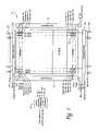
- FIG. 1is an illustration of a memory apparatus of a preferred embodiment.
- FIG. 2is a circuit diagram illustrating the dependence of a voltage across a memory cell on word line and bit line resistances.
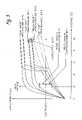
- FIG. 3is a graph of current-voltage curves for a forward-biased one-time programmable memory cell of a preferred embodiment illustrating an uncompensated memory read scenario.
- FIG. 4is a graph of current-voltage curves for a forward-biased one-time programmable memory cell of a preferred embodiment illustrating an address-dependent V diode compensated memory read scenario.
- FIG. 5is a graph of current-voltage curves for a forward-biased one-time programmable memory cell of a preferred embodiment illustrating an address-dependent I ref compensated memory read scenario.
- FIG. 6is a graph of current-voltage curves for a forward-biased one-time programmable memory cell of a preferred embodiment illustrating an uncompensated memory write sensing scenario.
- FIG. 7is a graph of current-voltage curves for a forward-biased one-time programmable memory cell of a preferred embodiment illustrating an address-dependent V write compensated memory write sensing scenario.
- FIG. 8is a graph of current-voltage curves for a forward-biased one-time programmable memory cell of a preferred embodiment illustrating an address-dependent I ref compensated memory write sensing scenario.
- FIG. 9is an illustration of a memory apparatus of another preferred embodiment.
- FIG. 10is a circuit diagram illustrating the dependence of a voltage across a memory cell on word line resistance with adjacent selected memory cells.
- FIG. 1is an illustration of a memory apparatus 5 of a preferred embodiment.
- the apparatus 5can be part of a modular, compact, handheld unit, such as a memory card or stick, used in a consumer electronics device such as, but not limited to, a digital camera, a personal digital assistant, a cellular phone, a digital audio player, or a personal computer.
- the apparatus 5comprises a plurality of word lines (WL[ 0 ], WL[ 1 ] . . . WL[Y- 2 ], WL[Y- 1 ]), a plurality of bit lines (BL[ 0 ], BL[ 1 ] . . .
- the memory cells 10can take any suitable form, including, but not limited to, write-once memory cells (i.e., one-time programmable), write-many memory cells, few-time programmable memory cells (i.e., memory cells that are programmable more than once but not as many times as a write-many memory cell), or any combination thereof.
- the memory cellscan be organized in a single layer (i.e., a two-dimensional array) or in a plurality of layers stacked vertically above one another above a single substrate (i.e., a three-dimensional array), as described in U.S. Pat. No. 6,034,882 to Johnson et al. and U.S. Pat. No. 6,420,215 to Knall et al., both of which are assigned to the assignee of the present invention and are hereby incorporated by reference.
- the memory celltakes the form of a semiconductor antifuse, whose dielectric is ruptured when programmed. Other types of memory cells can be used.
- the apparatus 5also comprises a row decoder 15 and a column decoder 20 that are coupled with the word lines and bit lines, respectively.
- the phrase “coupled with”means directly coupled with or indirectly coupled with through one or more named or unnamed components.
- Both the row decoder 15 and the column decoder 20are split on opposite sides of the memory array.
- the row decoder 15comprises a plurality of word line drivers 25 , one for each word line.
- the column decoder 20comprises a plurality of bit line drivers (not shown), one for each bit line.
- the apparatus 5also comprises a plurality of sense amplifiers 30 coupled with the column decoder 20 , as well as an address-dependent voltage and current generator 35 , which selects a writing and/or reading condition to apply to a memory cell based on the memory cell's location with respect to one or both of a word line driver and a bit line driver, as will be discussed in further detail below.
- a row addressis provided to the row decoder 15
- a column addressis provided to the column decoder 20 .
- the row decoder 15 and column decoder 20determine which word line and bit line, respectively, correspond to the provided row and column address, and the apparatus 5 applies a writing condition or reading condition to the selected memory cell.
- the terms “writing condition” and “reading condition”can refer to one or both of a forcing function and a reference.
- a forcing functioncan be, for example, a voltage source, a current source, a generated wave shape (e.g., high impedance or low impedance), a charge packet, or other driving stimuli.
- a referencecan be, for example, a current reference or a voltage reference. Other types of writing and reading conditions can be used.
- the word line and bit line drivers associated with the memory cellare driven with a supplied word line voltage (V WL ) and bit line voltage (V BL ), respectively.
- a supplied voltagecan be ground.
- the memory cellis programmed when the voltage across the memory cell is greater than a threshold voltage.
- the supplied word line and bit line voltagesare the “writing condition.”
- the “writing condition”would be both the supplied word line and bit line voltages, as well as the reference current.
- Smart writecompares the current flowing out of a memory cell to a reference current while the memory cell is being programmed.
- the word line and bit line drivers associated with the memory cellare driven with a supplied word line voltage (V WL ) and bit line voltage (V BL ), respectively, and the sense amplifier 30 associated with the memory cell compares the current flowing out of the memory cell to a reference current. If the memory cell is programmed, the current will be greater than the reference current; otherwise, the current will be lower than the reference current.
- the “reading condition”is the supplied word line voltage (V WL ) and bit line voltage (V BL ) and the reference current. As mentioned above, writing and reading conditions can take other forms.
- the total equivalent resistance (R)comprises the pull-up resistance in the column decoder 20 (R pu ), the pull-down resistance in column decoder 20 (R pd ), the bit line resistance (R bl ), and the word line resistance (R wl ).
- the voltage drop across the memory cell (V diode )also causes a drop in the memory cell current (I D ). Accordingly, the voltage applied to a memory cell and the current read from a memory cell depend on the memory cell's location with respect to one or both of a word line driver and a bit line driver, as the bit line and word line resistances increase as the memory cell is located further along a bit line and a word line, respectively.
- a far-far bitis a memory cell furthest from the word line driver and furthest from the bit line driver within a single memory array.
- a far-near bitis a memory cell farthest from the word line driver and closest to the bit line driver within a single memory array.
- a near-far bitis a memory cell closest to the word line driver and furthest from the bit line driver within a single memory array.
- a near-near bitis a memory cell closest to the word line driver and closest to the bit line driver within a single memory array.
- a near-near bitis a memory cell closest to the word line driver and closest to the bit line driver within a single memory array.
- other categoriescan be used.
- a memory cellis subjected to conditions (e.g., resistances) that vary based on the location of the memory cell in reference to the word line and bit line select circuits (i.e., drivers), applying the same writing and reading conditions to all memory cells in the array can result in programming and reading errors.
- conditionse.g., resistances
- bit line select circuitsi.e., drivers
- applying the same writing and reading conditions to all memory cells in the arraycan result in programming and reading errors.
- a well-controlled voltageis applied at the word line and bit line driver outputs.
- the actual voltage across memory cellis lower if it were a far-far bit than if it were a near-near bit because the resistance of along the word line and the bit line causes the voltage to drop.
- a variation in actual voltage across the memory cellwould cause a reduction in read margin, a reduction in programming margin, and a reduction in write sensing margin.
- FIG. 3is a graph of current-voltage curves for a forward-biased one-time programmable memory cell in the near-near and far-far fields in both programmed and unprogrammed states.
- the two curves shown for each type of memory cellrepresent the lower and upper limits in a distribution that is caused from variations in the manufacturing process, for example.
- near-near programmed bitsgenerate greater memory cell current than far-far programmed bits. The same is true for unprogrammed bits.
- the read margin(or read sensing window) is the tolerance in total allowable variations in voltage and current that can be accepted for correct reading
- the overall read voltagecan be raised to accommodate for the high resistance seen by a far-far bit.
- the increased voltagecould cause a leaky unprogrammed near-near bit to conduct more current than the reference current, which would result in the unprogrammed near-near memory cell being misinterpreted as being in a programmed state.
- the same problemoccurs if the read voltage fluctuates. If the read voltage drops below two volts, the current conducted by a weakly-programmed far-far bit falls within the read window. That is, the read window that existed at two volts no longer exists.
- the apparatus 5can comprise circuitry that selects a reading condition (e.g., voltage or reference current) to apply to a memory cell that depends on the memory cell's location with respect to one or both of a word line driver and a bit line driver. This can be accomplished by selecting a condition to apply to a memory cell that is address-dependent to compensate for the problem.
- a reading conditione.g., voltage or reference current
- Thiscan be accomplished by selecting a condition to apply to a memory cell that is address-dependent to compensate for the problem.
- a windowcan be created by applying address-dependent reading conditions. Even if an operating window exists, using address-dependent reading conditions can improve the robustness of the design by increasing the read margin.
- FIGS. 4 and 5illustrate how circuitry can compensate for the voltage and current drops by adjusting the applied voltage and the reference current, respectively, based on the memory cell's location/address.
- FIG. 4by applying a lower V read for near-near bits than for far-far bits, a wider read margin is present.
- FIG. 5the read voltage is kept constant, but the reference current is changed depending on whether the memory cell being read is a near-near bit or a far-far bit.
- varying reference current based on addressprovides for a larger read margin than in the uncompensated case shown in FIG. 3 . It is important to note that while FIGS. 4 and 5 show one of the voltage and reference current being fixed while the other is varied, both the voltage and reference current can vary together.
- a write sensing problemexists when a sensing-while-programming (“smart write”) technique is used.
- the smart write techniquecompares the current flowing out of a memory cell to a reference current while the memory cell is being programmed. Once the current exceeds the reference current (indicating that the memory cell has been programmed), the write cycle for that memory cell ends, and the write cycle for another memory cell begins.
- This techniqueincreases programming bandwidth especially when a group of memory cells is programmed in parallel along the same physical word line.
- the write currentcan be limited in this situation, and the current limit is also used as a current reference to sense back the programming of the memory cell. In some situations, this results in no window for write sensing.
- FIG. 6is a graph that illustrates this problem.
- the current passing through a weakly-programmed far-far bitwill be less than the reference current, resulting in the programmed memory cell being read as an unprogrammed bit. Accordingly, it is desired to set the reference current such that all the programmed cells are above the current reference, and all the unprogrammed cells are below the current reference.
- the same current reference settingmay be higher than the far-far programmed bits, as shown in FIG. 6 . This will cause a write timeout for far-far programmed bits.
- the current referenceis set to accommodate the far-far bits, the same current reference setting may be lower than the near-near unprogrammed bits. This will cause the “smart-write” circuitry to think that the near-near unprogrammed bit has been programmed and to move onto the next set of bits prematurely.
- the apparatus 5can comprise circuitry that selects a writing condition (e.g., voltage or reference current) to apply to a memory cell that depends on the memory cell's location (e.g., is an address-dependent reading condition).
- a writing conditione.g., voltage or reference current
- FIGS. 7 and 8illustrate how this circuitry can compensate for the voltage and current drops by adjusting the applied voltage and the reference current, respectively, based on the memory cell's location/address. As shown in FIG. 7 , by applying a lower V write for near-near bits than for far-far bits, a wider write-sensing margin is present.
- the write voltageis kept constant, but the reference current is changed depending on whether the memory cell being read is a near-near bit or a far-far bit.
- varying reference currentbased on address provides a larger write-sensing margin than in the uncompensated case shown in FIG. 6 . It is important to note that while FIG. 7 and 8 show one of the voltage and reference current being fixed while the other is varied, both the voltage and reference current can vary together.
- the address-dependent write conditionwas tailored to provide an adequate write sensing window.
- an address-dependent write conditioncan be used to counterbalance the reduction in programming margin.
- near-near bits that are to be programmedmay experience excessive power being delivered.
- thismay result in the memory cell being overstressed, causing the antifuse to breakdown and creating an open instead of a short.
- it is more difficult to program far-far bits than near-near bitsbecause less power is delivered to a far-far memory cell due to the higher resistance on the memory line.
- the power delivered to near-near bitscan be reduced by lowering the voltages across the memory cell based on the address of the memory cell.
- the power delivered to far-far bitscan be increased by increasing the voltages across the memory cell based on the address of the memory cell.
- a memory apparatuscan comprise circuitry that is operative to select a writing and/or reading condition to apply to a memory cell based on the memory cell's location with respect to one or both of a word line driver and a bit line driver.
- circuitrycan take any suitable form and, by way of example only, can include pure hardware components (e.g., resistors, capacitors, voltage sources, etc.), a general-purpose processor executing computer-executable program code, an application specific integrated circuit, and a programmable logic controller. It is important to note that other circuitry designs and components can be used, and the term “circuitry” in the claims should not be limited to the examples of circuitry shown in the drawings and described below.
- the circuitry in that apparatus 5takes the form of an address-dependent voltage and current generator 35 .
- the address-dependent voltage and current generator 35selects a writing and/or reading condition to apply to a memory cell based on the memory cell's location with respect to a bit line driver and not a word line driver.
- other circuitry designscan be used that select writing and/or reading conditions to apply to a memory cell based on the memory cell's location with respect to a word line driver and not a bit line driver or based on a memory cell's location with respect to both a word line driver and a bit line driver.
- the memory cellsare organized into a plurality of zones that comprise a plurality of word lines.
- predetermined read/write voltages and currentsare determined and used for memory operations. In this way, the generated voltages and currents for a memory operation are modulated by the address bits in a discrete manner.
- the address-dependent voltage and current generator 35determines what zone a given memory cell belongs to based on the memory cell's row and column address and applies the appropriate writing and/or reading condition for that zone (i.e., the appropriate word line voltage (V WL ), bit line voltage (V BL ), reference current for the top set of sense amplifiers (I REF — TOP ), and reference current for the bottom set of sense amplifiers (I REF — TOP )). In this way, different writing and/or reading conditions are applied to different zones.
- V WLword line voltage
- V BLbit line voltage
- I REF — TOPreference current for the top set of sense amplifiers
- I REF — TOPreference current for the bottom set of sense amplifiers
- Table 1shows a zone organization scheme of one presently preferred embodiment that applies both varying voltage and reference current based on zone location, and Table 2 shows an example of this scheme for both read and write scenarios.
- NNumber of Row Address bits
- NNumber of Zones defined 2
- TopRefers to memory cells on bitlines driven by “top” column decoder.
- BottomRefers to memory cells on bitlines driven by “bottom” column decoder.
- the address-dependent voltage and current generator 35supplies less of a voltage to memory cells closer to a bit line driver than to memory cells farther from a bit line driver and selects a greater reference current to apply to memory cells closer to a bit line driver than to memory cells farther from a bit line driver.
- the memory cellswere organized into zones that run parallel to the word lines.
- the result of this organizationis that writing and/or reading conditions varied based on a memory cell's location with respect to a bit line driver (and not a word line driver) since a memory cell's location with respect to a bit line driver is what determines which zone the memory cell is in, and, hence, which writing and/or reading conditions are applied to that cell.
- all the memory cells along a word line in a given zonewere supplied with same word line voltage irrespective of the memory cell's location along a word line.
- different operating condition zonesrun parallel to the bit lines (i.e., the zones comprise a plurality of bit lines), and, hence, the writing and/or reading conditions are varied based on a memory cell's location with respect to a word line driver (and not a bit line driver).
- This designis useful when a number of bits are selected in parallel during a write operation.
- the dynamic selection of number of bits in parallel for programmingcan be achieved in the same manner as with the zones shown in FIG. 1 .
- a predetermined number of bitsare selected to be programmed in parallel. In a normal page write operation, a zone will be selected in sequence.
- the number of bits selected in parallelwill dynamically change as the page is programmed.
- Ris the total equivalent resistance, which comprises pull-up resistance in the column decoder (R pu ) 120 , pull-down resistance in the column decoder 120 (R pd ), and word line resistance (R wl ).
- I Dis the memory cell current
- V diodeis the voltage across the memory cell
- V WRis the write voltage supply
- V BLis the bit line voltage supply
- V WLis the word line voltage supply.
- V WRV BL ⁇ V WL
- V EQis the equivalent voltage by adjacent programmed memory cells.
- the overall write bandwidthcan be increased by changing the number of bits that are programmed in parallel given the address location of the selected memory cells.
- V EQis higher for selected bits closer to the write driver than for selected bits that are farther away. Therefore, the power delivering to the all the memory cells are the same along the word line.
- the number of bits that are programmedcan be dynamically switched as the memory cells are being programmed along a selected word line.
- Table 3shows a zone organization scheme of one presently preferred embodiment in which an address determines the number of bits selected to be programmed in parallel, and Table 4 shows an example of this scheme.
- NN ⁇ 1 BL[(K:0) + (K + 1)*ZONE] min max
- XNumber of Column Address bits
- NNumber of Zones defined 2
- RightRefers to memory cells on wordlines driven by “right” row decoder
- FIGS. 1 and 9show a “horizontal” zone scheme being used independently from a “vertical” zone scheme
- both “horizontal” and “vertical” zone schemescan be used simultaneously such as to vary writing and/or reading conditions based on a memory cell's location with respect to both a word line driver and a bit line driver.
- word lines or bit lineswere grouped in zones, and the writing and/or reading condition applied to a memory cell depended upon which zone the memory cell belonged to.
- writing and/or reading conditionscan be determined based purely on the memory cell's address without using the concept of zones.
- each memory cellhas a unique set of operating conditions applied. The end result is that each memory cell will look exactly the same as each other. In this design, each memory cell can be considered as having its own zone.
- writing and/or reading conditionscan be used to vary writing conditions (without varying reading conditions), reading conditions (without varying writing conditions), or both writing and reading conditions.
- the preferred embodiments described abovevary writing and/or reading conditions based on a memory cell's address because the address provides an indication of the memory cell's location with respect to a word line and/or bit line driver.
- a metric other than address that indicates the memory cell's location with respect to a word line and/or bit line driveris used to vary writing and/or reading conditions.
- the address-dependent voltage and current generatorsselect word and bit line voltages and reference currents to apply to a memory cell based on a zone associated with that memory cell.
- the circuitryonly provides an address-dependent reference current, and the word line and/or bit line drivers in the row and column decoders have their own word line and bit line voltage generators, with the generators providing the voltage appropriate for their respective zones.
Landscapes
- Engineering & Computer Science (AREA)
- Computer Hardware Design (AREA)
- Microelectronics & Electronic Packaging (AREA)
- Read Only Memory (AREA)
- Semiconductor Memories (AREA)
- Static Random-Access Memory (AREA)
- Transceivers (AREA)
- Debugging And Monitoring (AREA)
Abstract
Description
| TABLE 1 | ||||
| Row Address | Voltage Applied | Reference Current | ||
| Zone | (2Ywordlines) | Top | Top | Bottom | ||
| 0 | WL[(J:0) + (J + 1)*ZONE] | max | min | max | ||
| 1 | WL[(J:0) + (J + 1)*ZONE] | . . . | . . . | . . . | . . . | |
| . | . . . | . . . | . . . | . . . | . . . | |
| . | . . . | . . . | . . . | . . . | . . . | |
| . | . . . | . . . | . . . | . . . | . . . | |
| N − 1 | WL[(J:0) + (J + 1)*ZONE] | min | max | max | min | |
| Legend: | ||||||
| Y = Number of Row Address bits | ||||||
| N = Number of Zones defined | ||||||
| 2Y/N = Number of wordlines in each zone | ||||||
| J = (2Y/N) − 1 | ||||||
| Top = Refers to memory cells on bitlines driven by “top” column decoder. | ||||||
| Bottom = Refers to memory cells on bitlines driven by “bottom” column decoder. | ||||||
| TABLE 2 | |||
| READ | WRITE | ||
| Row Address | Vdiode(V) | Iref(nA) | Vdiode(V) | Iref(μA) |
| Zone | RAD[4:0] | Top | Bottom | Top | Bottom | Top | Top | Bottom | ||
| 0 | WL[7:0] | 2.4 | 2.1 | 222 | 333 | 9.5 | 8 | 100 | 214 |
| 1 | WL[15:8] | 2.3 | 2.2 | 250 | 250 | 9 | 8.5 | 134 | 160 |
| 2 | WL[23:16] | 2.2 | 2.3 | 250 | 250 | 8.5 | 9 | 160 | 134 |
| 3 | WL[31:24] | 2.1 | 2.4 | 333 | 222 | 8 | 9.5 | 214 | 100 |
| Example: | |||||||||
| Y = 5 | |||||||||
| N = 4 | |||||||||
| 2Y/N = 8 | |||||||||
| J = 7 | |||||||||
| Top = Refers to memory cells on bitlines driven by “top” column decoder. | |||||||||
| Bottom = Refers to memory cells on bitlines driven by “bottom” column decoder. | |||||||||
| TABLE 3 | ||
| Number of bits to | ||
| Program in Parallel | ||
| Column Address | WL Driver | WL Driver | ||
| Zone | (2Xbitlines) | (left) | (right) | |
| 0 | BL[(K:0) + (K + 1)*ZONE] | min | ||
| 1 | BL[(K:0) + (K + 1)*ZONE] | . . . | . . . | |
| . | . . . | . . . | . . . | |
| . | . . . | . . . | . . . | |
| . | . . . | . . . | . . . | |
| N − 1 | BL[(K:0) + (K + 1)*ZONE] | min | max | |
| Legend: | ||||
| X = Number of Column Address bits | ||||
| N = Number of Zones defined | ||||
| 2X/N = Number of bitlines in each zone | ||||
| K = (2X/N) − 1 | ||||
| Left = Refers to memory cells on wordlines driven by “left” row decoder | ||||
| Right = Refers to memory cells on wordlines driven by “right” row decoder | ||||
| TABLE 4 | ||||
| Number of bits to | ||||
| Column Address | Program in Parallel | |||
| Zone | (CAD[4:0]) | RAD[0] = 0 | RAD[0] = 1 |
| 0 | BL[7:0] | 16 | 4 |
| 1 | BL[15:8] | 8 | 8 |
| 2 | BL[23:16] | 8 | 8 |
| 3 | BL[31:24] | 4 | 16 |
| Example: | |||
| X = 5 | |||
| N = 4 | |||
| 2X/N = 8 | |||
| K = 7 | |||
Claims (45)
Priority Applications (8)
| Application Number | Priority Date | Filing Date | Title |
|---|---|---|---|
| US11/015,440US7218570B2 (en) | 2004-12-17 | 2004-12-17 | Apparatus and method for memory operations using address-dependent conditions |
| DE602005026052TDE602005026052D1 (en) | 2004-12-17 | 2005-11-29 | DEVICE AND METHOD FOR MEMORY OPERATIONS USING ADDRESS-RELATED CONDITIONS |
| CN200580042742XACN101208751B (en) | 2004-12-17 | 2005-11-29 | Apparatus and method for memory operation using address-related conditions |
| KR1020077013751AKR101100805B1 (en) | 2004-12-17 | 2005-11-29 | Memory operating apparatus and method using address-dependent condition |
| EP05852375AEP1825475B1 (en) | 2004-12-17 | 2005-11-29 | Apparatus and method for memory operations using address-dependent conditions |
| JP2007546708AJP5285277B2 (en) | 2004-12-17 | 2005-11-29 | Apparatus and method for memory operation using address dependent conditions |
| AT05852375TATE496372T1 (en) | 2004-12-17 | 2005-11-29 | APPARATUS AND METHOD FOR STORAGE OPERATIONS USING ADDRESS DEPENDENT CONDITIONS |
| PCT/US2005/043074WO2006065523A2 (en) | 2004-12-17 | 2005-11-29 | Apparatus and method for memory operations using address-dependent conditions |
Applications Claiming Priority (1)
| Application Number | Priority Date | Filing Date | Title |
|---|---|---|---|
| US11/015,440US7218570B2 (en) | 2004-12-17 | 2004-12-17 | Apparatus and method for memory operations using address-dependent conditions |
Publications (2)
| Publication Number | Publication Date |
|---|---|
| US20060133125A1 US20060133125A1 (en) | 2006-06-22 |
| US7218570B2true US7218570B2 (en) | 2007-05-15 |
Family
ID=36588354
Family Applications (1)
| Application Number | Title | Priority Date | Filing Date |
|---|---|---|---|
| US11/015,440Expired - LifetimeUS7218570B2 (en) | 2004-12-17 | 2004-12-17 | Apparatus and method for memory operations using address-dependent conditions |
Country Status (8)
| Country | Link |
|---|---|
| US (1) | US7218570B2 (en) |
| EP (1) | EP1825475B1 (en) |
| JP (1) | JP5285277B2 (en) |
| KR (1) | KR101100805B1 (en) |
| CN (1) | CN101208751B (en) |
| AT (1) | ATE496372T1 (en) |
| DE (1) | DE602005026052D1 (en) |
| WO (1) | WO2006065523A2 (en) |
Cited By (20)
| Publication number | Priority date | Publication date | Assignee | Title |
|---|---|---|---|---|
| US20070263469A1 (en)* | 2006-05-15 | 2007-11-15 | Apple Inc. | Two Levels of Voltage Regulation Supplied for Logic and Data Programming Voltage of a Memory Device |
| US20070263439A1 (en)* | 2006-05-15 | 2007-11-15 | Apple Inc. | Dynamic Cell Bit Resolution |
| US20070263440A1 (en)* | 2006-05-15 | 2007-11-15 | Apple Inc. | Multi-Chip Package for a Flash Memory |
| US20070263442A1 (en)* | 2006-05-15 | 2007-11-15 | Apple Inc. | Off-Die Charge Pump that Supplies Multiple Flash Devices |
| US20070263454A1 (en)* | 2006-05-15 | 2007-11-15 | Apple Inc. | Maintenance Operations for Multi-Level Data Storage Cells |
| US20070263441A1 (en)* | 2006-05-15 | 2007-11-15 | Apple Inc. | Analog Interface for a Flash Memory Die |
| US20080013380A1 (en)* | 2006-05-15 | 2008-01-17 | Apple Inc. | Shifting Reference Values to Account for Voltage Sag |
| US20090147570A1 (en)* | 2006-05-15 | 2009-06-11 | Apple Inc. | Use of 8-bit or higher a/d for nand cell value |
| US20090219741A1 (en)* | 2008-02-28 | 2009-09-03 | Shepard Daniel R | Diagonal connection storage array |
| US20090237994A1 (en)* | 2006-05-15 | 2009-09-24 | Cornwell Michael J | Iterative Memory Cell Charging Based on Reference Cell Value |
| US20100054044A1 (en)* | 2008-09-03 | 2010-03-04 | Ji Hyun Seo | Method of operating nonvolatile memory device |
| US20100214843A1 (en)* | 2009-02-25 | 2010-08-26 | Soo-Han Kim | Nonvolatile memory device and memory system having the same |
| US20100321977A1 (en)* | 2009-06-19 | 2010-12-23 | Sekar Deepak C | Programming reversible resistance switching elements |
| US8127202B2 (en) | 2006-05-15 | 2012-02-28 | Apple Inc. | Use of alternative value in cell detection |
| US8902635B2 (en) | 2011-11-29 | 2014-12-02 | Panasonic Corporation | Variable resistance nonvolatile memory device and method of writing thereby |
| US9406377B2 (en) | 2014-12-08 | 2016-08-02 | Sandisk Technologies Llc | Rewritable multibit non-volatile memory with soft decode optimization |
| US20160379707A1 (en)* | 2015-06-25 | 2016-12-29 | Research & Business Foundation Sungkyunkwan University | Cross point memory device |
| US20170192711A1 (en)* | 2014-07-31 | 2017-07-06 | Hewlett Packard Enterprise Development Lp | Encoding data within a crossbar memory array |
| US20180061504A1 (en)* | 2016-08-26 | 2018-03-01 | Samsung Electronics Co., Ltd. | Non-Volatile Memory Devices Having Temperature and Location Dependent Word Line Operating Voltages |
| US11342019B2 (en)* | 2019-09-27 | 2022-05-24 | Taiwan Semiconductor Manufacturing Co., Ltd. | Compensation word line driver |
Families Citing this family (16)
| Publication number | Priority date | Publication date | Assignee | Title |
|---|---|---|---|---|
| US7283414B1 (en) | 2006-05-24 | 2007-10-16 | Sandisk 3D Llc | Method for improving the precision of a temperature-sensor circuit |
| US20080135087A1 (en)* | 2007-05-10 | 2008-06-12 | Rangappan Anikara | Thin solar concentrator |
| US20090225621A1 (en)* | 2008-03-05 | 2009-09-10 | Shepard Daniel R | Split decoder storage array and methods of forming the same |
| KR101424139B1 (en)* | 2008-08-01 | 2014-08-04 | 삼성전자주식회사 | Nonvolatile memory device and method of operation thereof |
| JP5193796B2 (en)* | 2008-10-21 | 2013-05-08 | 株式会社東芝 | Three-dimensional stacked nonvolatile semiconductor memory |
| US8446787B2 (en)* | 2008-11-20 | 2013-05-21 | Micron Technology, Inc. | Replacing defective memory blocks in response to external addresses |
| JP5259552B2 (en)* | 2009-11-02 | 2013-08-07 | 株式会社東芝 | Nonvolatile semiconductor memory device and driving method thereof |
| US8089815B2 (en)* | 2009-11-24 | 2012-01-03 | Sandisk Technologies Inc. | Programming memory with bit line floating to reduce channel-to-floating gate coupling |
| TWI497496B (en)* | 2011-01-19 | 2015-08-21 | Macronix Int Co Ltd | Architecture for 3d memory array |
| KR20130070928A (en)* | 2011-12-20 | 2013-06-28 | 에스케이하이닉스 주식회사 | Semiconductor memory device and method of operating thesame |
| KR20140025164A (en)* | 2012-08-21 | 2014-03-04 | 삼성전자주식회사 | Nonvolitile memory device and data processing methods thereof |
| US8885400B2 (en) | 2013-02-21 | 2014-11-11 | Sandisk 3D Llc | Compensation scheme for non-volatile memory |
| JP6457364B2 (en)* | 2015-09-11 | 2019-01-23 | 東芝メモリ株式会社 | Memory system |
| JP2018160295A (en) | 2017-03-22 | 2018-10-11 | 東芝メモリ株式会社 | Semiconductor memory |
| CN108492844B (en)* | 2018-03-26 | 2020-10-16 | 上海华虹宏力半导体制造有限公司 | Double-split gate flash memory array and programming method thereof |
| US11081151B2 (en)* | 2019-09-26 | 2021-08-03 | Intel Corporation | Techniques to improve a read operation to a memory array |
Citations (61)
| Publication number | Priority date | Publication date | Assignee | Title |
|---|---|---|---|---|
| US3851316A (en) | 1971-09-07 | 1974-11-26 | Tokyo Shibaura Electric Co | Semiconductor memory device |
| US4592027A (en) | 1983-02-15 | 1986-05-27 | Sharp Kabushiki Kaisha | Read control circuit in a read only memory system |
| US4646266A (en) | 1984-09-28 | 1987-02-24 | Energy Conversion Devices, Inc. | Programmable semiconductor structures and methods for using the same |
| US4646269A (en) | 1984-09-18 | 1987-02-24 | Monolithic Memories, Inc. | Multiple programmable initialize words in a programmable read only memory |
| US4698788A (en) | 1985-07-01 | 1987-10-06 | Motorola, Inc. | Memory architecture with sub-arrays |
| US4744061A (en) | 1983-11-25 | 1988-05-10 | Fujitsu Limited | Dynamic semiconductor memory device having a simultaneous test function for divided memory cell blocks |
| US4873669A (en) | 1986-07-30 | 1989-10-10 | Mitsubishi Denki Kabushiki Kaisha | Random access memory device operable in a normal mode and in a test mode |
| US5107139A (en) | 1990-03-30 | 1992-04-21 | Texas Instruments Incorporated | On-chip transient event detector |
| US5149199A (en) | 1990-05-24 | 1992-09-22 | Kabushiki Kaisha Toshiba | Temperature detection circuit used in thermal shielding circuit |
| US5276649A (en) | 1989-03-16 | 1994-01-04 | Mitsubishi Denki Kabushiki Kaisha | Dynamic-type semiconductor memory device having staggered activation of column groups |
| US5276644A (en) | 1990-11-19 | 1994-01-04 | Sgs-Thomson Microelectronics, S.R.L. | Sense circuit for storage devices such as non-volatile memories, with compensated offset current |
| US5278796A (en) | 1991-04-12 | 1994-01-11 | Micron Technology, Inc. | Temperature-dependent DRAM refresh circuit |
| US5359571A (en) | 1993-01-27 | 1994-10-25 | Yu Shih Chiang | Memory array having a plurality of address partitions |
| US5383157A (en) | 1993-08-06 | 1995-01-17 | Cypress Semiconductor Corporation | Parallel TESTMODE |
| US5410512A (en) | 1992-05-22 | 1995-04-25 | Kabushiki Kaisha Toshiba | Semiconductor memory device |
| US5652722A (en) | 1994-08-26 | 1997-07-29 | Sgs-Thomson Microelectronics Limited | System and method for controlling voltage and current characteristics of bit lines in a memory array |
| US5745410A (en) | 1995-11-17 | 1998-04-28 | Macronix International Co., Ltd. | Method and system for soft programming algorithm |
| US5784328A (en) | 1996-12-23 | 1998-07-21 | Lsi Logic Corporation | Memory system including an on-chip temperature sensor for regulating the refresh rate of a DRAM array |
| US5818748A (en) | 1995-11-21 | 1998-10-06 | International Business Machines Corporation | Chip function separation onto separate stacked chips |
| US5835396A (en) | 1996-10-17 | 1998-11-10 | Zhang; Guobiao | Three-dimensional read-only memory |
| US5890100A (en) | 1997-08-19 | 1999-03-30 | Advanced Micro Devices, Inc. | Chip temperature monitor using delay lines |
| US5923588A (en) | 1993-08-27 | 1999-07-13 | Kabushiki Kaisha Toshiba | Non-volatile semiconductor memory device with a plurality of programming voltage levels |
| US5925996A (en) | 1997-10-10 | 1999-07-20 | Whistler Corporation Of Massachusetts | Garage door operator motor secondary thermal overload |
| US5940340A (en) | 1993-06-14 | 1999-08-17 | Rambus, Inc. | Method and apparatus for writing to memory components |
| US5961215A (en) | 1997-09-26 | 1999-10-05 | Advanced Micro Devices, Inc. | Temperature sensor integral with microprocessor and methods of using same |
| US5977746A (en) | 1998-07-21 | 1999-11-02 | Stryker Corporation | Rechargeable battery pack and method for manufacturing same |
| US6034918A (en) | 1990-04-18 | 2000-03-07 | Rambus Inc. | Method of operating a memory having a variable data output length and a programmable register |
| US6034882A (en) | 1998-11-16 | 2000-03-07 | Matrix Semiconductor, Inc. | Vertically stacked field programmable nonvolatile memory and method of fabrication |
| US6055180A (en) | 1997-06-17 | 2000-04-25 | Thin Film Electronics Asa | Electrically addressable passive device, method for electrical addressing of the same and uses of the device and the method |
| US6157244A (en) | 1998-10-13 | 2000-12-05 | Advanced Micro Devices, Inc. | Power supply independent temperature sensor |
| US6185712B1 (en) | 1998-07-02 | 2001-02-06 | International Business Machines Corporation | Chip performance optimization with self programmed built in self test |
| US6185121B1 (en) | 1998-02-26 | 2001-02-06 | Lucent Technologies Inc. | Access structure for high density read only memory |
| US6191980B1 (en)* | 2000-03-07 | 2001-02-20 | Lucent Technologies, Inc. | Single-poly non-volatile memory cell having low-capacitance erase gate |
| US6205074B1 (en) | 2000-02-29 | 2001-03-20 | Advanced Micro Devices, Inc. | Temperature-compensated bias generator |
| US6208545B1 (en) | 1997-04-04 | 2001-03-27 | Glenn J. Leedy | Three dimensional structure memory |
| US6212121B1 (en) | 1998-12-02 | 2001-04-03 | Samsung Electronics Co., Ltd. | Semiconductor memory device with multiple sub-arrays of different sizes |
| US6236587B1 (en) | 1997-09-01 | 2001-05-22 | Thin Film Electronics Asa | Read-only memory and read-only memory devices |
| US6240046B1 (en) | 1999-02-13 | 2001-05-29 | Integrated Device Technology, Inc. | Integrated circuit random access memory capable of reading either one or more than one data word in a single clock cycle |
| US6246610B1 (en) | 2000-02-22 | 2001-06-12 | Advanced Micro Devices, Inc. | Symmetrical program and erase scheme to improve erase time degradation in NAND devices |
| US6335889B1 (en) | 1999-10-18 | 2002-01-01 | Nec Corporation | Semiconductor memory device |
| US20020028541A1 (en) | 2000-08-14 | 2002-03-07 | Lee Thomas H. | Dense arrays and charge storage devices, and methods for making same |
| US6356485B1 (en) | 1999-02-13 | 2002-03-12 | Integrated Device Technology, Inc. | Merging write cycles by comparing at least a portion of the respective write cycle addresses |
| US6373768B2 (en) | 1998-07-16 | 2002-04-16 | Rambus Inc | Apparatus and method for thermal regulation in memory subsystems |
| US6385074B1 (en) | 1998-11-16 | 2002-05-07 | Matrix Semiconductor, Inc. | Integrated circuit structure including three-dimensional memory array |
| US6407953B1 (en) | 2001-02-02 | 2002-06-18 | Matrix Semiconductor, Inc. | Memory array organization and related test method particularly well suited for integrated circuits having write-once memory arrays |
| US6420215B1 (en) | 2000-04-28 | 2002-07-16 | Matrix Semiconductor, Inc. | Three-dimensional memory array and method of fabrication |
| US20020136047A1 (en) | 2001-03-21 | 2002-09-26 | Scheuerlein Roy E. | Method and apparatus for biasing selected and unselected array lines when writing a memory array |
| US20020136045A1 (en) | 2001-03-21 | 2002-09-26 | Scheuerlein Roy E. | Memory device with row and column decoder circuits arranged in a checkerboard pattern under a plurality of memory arrays |
| US6507238B1 (en) | 2001-06-22 | 2003-01-14 | International Business Machines Corporation | Temperature-dependent reference generator |
| US6525953B1 (en) | 2001-08-13 | 2003-02-25 | Matrix Semiconductor, Inc. | Vertically-stacked, field-programmable, nonvolatile memory and method of fabrication |
| US20030046020A1 (en) | 2001-08-31 | 2003-03-06 | Matrix Semiconductor, Inc. | Memory device and method for temperature-based control over write and/or read operations |
| US20030043643A1 (en) | 2001-08-31 | 2003-03-06 | Matrix Semiconductor, Inc. | Memory device and method for selectable sub-array activation |
| US6560152B1 (en) | 2001-11-02 | 2003-05-06 | Sandisk Corporation | Non-volatile memory with temperature-compensated data read |
| US6574145B2 (en) | 2001-03-21 | 2003-06-03 | Matrix Semiconductor, Inc. | Memory device and method for sensing while programming a non-volatile memory cell |
| US6577549B1 (en) | 2001-12-03 | 2003-06-10 | Hewlett-Packard Company, L.P. | Write current compensation for temperature variations in memory arrays |
| US6661730B1 (en) | 2000-12-22 | 2003-12-09 | Matrix Semiconductor, Inc. | Partial selection of passive element memory cell sub-arrays for write operation |
| US20040100831A1 (en) | 2002-11-27 | 2004-05-27 | Knall N. Johan | Integrated circuit and method for selecting a set of memory-cell-layer-dependent or temperature-dependent operating conditions |
| US6754124B2 (en) | 2002-06-11 | 2004-06-22 | Micron Technology, Inc. | Hybrid MRAM array structure and operation |
| US6791875B2 (en)* | 2001-08-09 | 2004-09-14 | Mitsubishi Denki Kabushiki Kaisha | Thin film magnetic memory device realizing both high-speed data reading operation and stable operation |
| US6925007B2 (en)* | 2001-10-31 | 2005-08-02 | Sandisk Corporation | Multi-state non-volatile integrated circuit memory systems that employ dielectric storage elements |
| US6980465B2 (en)* | 2003-12-19 | 2005-12-27 | Hewlett-Packard Development Company, L.P. | Addressing circuit for a cross-point memory array including cross-point resistive elements |
Family Cites Families (8)
| Publication number | Priority date | Publication date | Assignee | Title |
|---|---|---|---|---|
| US5798966A (en)* | 1997-03-31 | 1998-08-25 | Intel Corporation | Flash memory VDS compensation techiques to reduce programming variability |
| JP2001102552A (en)* | 1999-09-29 | 2001-04-13 | Sony Corp | Semiconductor storage device and reading method therefor |
| US6597609B2 (en)* | 2001-08-30 | 2003-07-22 | Micron Technology, Inc. | Non-volatile memory with test rows for disturb detection |
| JP2003109389A (en)* | 2001-09-28 | 2003-04-11 | Fujitsu Ltd | Semiconductor storage device |
| JP3812498B2 (en)* | 2001-12-28 | 2006-08-23 | 日本電気株式会社 | Semiconductor memory device using tunnel magnetoresistive element |
| KR100429891B1 (en)* | 2002-07-29 | 2004-05-03 | 삼성전자주식회사 | Grid clock distribution network for minimizing clock skew |
| JP2004158119A (en)* | 2002-11-06 | 2004-06-03 | Sharp Corp | Nonvolatile semiconductor memory device |
| KR100488544B1 (en)* | 2002-11-11 | 2005-05-11 | 삼성전자주식회사 | Device and method for controlling aivc voltage using block selection information in semiconductor memory |
- 2004
- 2004-12-17USUS11/015,440patent/US7218570B2/ennot_activeExpired - Lifetime
- 2005
- 2005-11-29ATAT05852375Tpatent/ATE496372T1/ennot_activeIP Right Cessation
- 2005-11-29WOPCT/US2005/043074patent/WO2006065523A2/enactiveApplication Filing
- 2005-11-29EPEP05852375Apatent/EP1825475B1/ennot_activeNot-in-force
- 2005-11-29CNCN200580042742XApatent/CN101208751B/enactiveActive
- 2005-11-29KRKR1020077013751Apatent/KR101100805B1/ennot_activeExpired - Fee Related
- 2005-11-29DEDE602005026052Tpatent/DE602005026052D1/enactiveActive
- 2005-11-29JPJP2007546708Apatent/JP5285277B2/enactiveActive
Patent Citations (64)
| Publication number | Priority date | Publication date | Assignee | Title |
|---|---|---|---|---|
| US3851316A (en) | 1971-09-07 | 1974-11-26 | Tokyo Shibaura Electric Co | Semiconductor memory device |
| US4592027A (en) | 1983-02-15 | 1986-05-27 | Sharp Kabushiki Kaisha | Read control circuit in a read only memory system |
| US4744061A (en) | 1983-11-25 | 1988-05-10 | Fujitsu Limited | Dynamic semiconductor memory device having a simultaneous test function for divided memory cell blocks |
| US4646269A (en) | 1984-09-18 | 1987-02-24 | Monolithic Memories, Inc. | Multiple programmable initialize words in a programmable read only memory |
| US4646266A (en) | 1984-09-28 | 1987-02-24 | Energy Conversion Devices, Inc. | Programmable semiconductor structures and methods for using the same |
| US4698788A (en) | 1985-07-01 | 1987-10-06 | Motorola, Inc. | Memory architecture with sub-arrays |
| US4873669A (en) | 1986-07-30 | 1989-10-10 | Mitsubishi Denki Kabushiki Kaisha | Random access memory device operable in a normal mode and in a test mode |
| US5276649A (en) | 1989-03-16 | 1994-01-04 | Mitsubishi Denki Kabushiki Kaisha | Dynamic-type semiconductor memory device having staggered activation of column groups |
| US5107139A (en) | 1990-03-30 | 1992-04-21 | Texas Instruments Incorporated | On-chip transient event detector |
| US6070222A (en) | 1990-04-18 | 2000-05-30 | Rambus Inc. | Synchronous memory device having identification register |
| US6034918A (en) | 1990-04-18 | 2000-03-07 | Rambus Inc. | Method of operating a memory having a variable data output length and a programmable register |
| US5149199A (en) | 1990-05-24 | 1992-09-22 | Kabushiki Kaisha Toshiba | Temperature detection circuit used in thermal shielding circuit |
| US5276644A (en) | 1990-11-19 | 1994-01-04 | Sgs-Thomson Microelectronics, S.R.L. | Sense circuit for storage devices such as non-volatile memories, with compensated offset current |
| US5278796A (en) | 1991-04-12 | 1994-01-11 | Micron Technology, Inc. | Temperature-dependent DRAM refresh circuit |
| US5410512A (en) | 1992-05-22 | 1995-04-25 | Kabushiki Kaisha Toshiba | Semiconductor memory device |
| US5359571A (en) | 1993-01-27 | 1994-10-25 | Yu Shih Chiang | Memory array having a plurality of address partitions |
| US5940340A (en) | 1993-06-14 | 1999-08-17 | Rambus, Inc. | Method and apparatus for writing to memory components |
| US5383157A (en) | 1993-08-06 | 1995-01-17 | Cypress Semiconductor Corporation | Parallel TESTMODE |
| US5923588A (en) | 1993-08-27 | 1999-07-13 | Kabushiki Kaisha Toshiba | Non-volatile semiconductor memory device with a plurality of programming voltage levels |
| US5652722A (en) | 1994-08-26 | 1997-07-29 | Sgs-Thomson Microelectronics Limited | System and method for controlling voltage and current characteristics of bit lines in a memory array |
| US5745410A (en) | 1995-11-17 | 1998-04-28 | Macronix International Co., Ltd. | Method and system for soft programming algorithm |
| US5818748A (en) | 1995-11-21 | 1998-10-06 | International Business Machines Corporation | Chip function separation onto separate stacked chips |
| US5835396A (en) | 1996-10-17 | 1998-11-10 | Zhang; Guobiao | Three-dimensional read-only memory |
| US5784328A (en) | 1996-12-23 | 1998-07-21 | Lsi Logic Corporation | Memory system including an on-chip temperature sensor for regulating the refresh rate of a DRAM array |
| US6208545B1 (en) | 1997-04-04 | 2001-03-27 | Glenn J. Leedy | Three dimensional structure memory |
| US6055180A (en) | 1997-06-17 | 2000-04-25 | Thin Film Electronics Asa | Electrically addressable passive device, method for electrical addressing of the same and uses of the device and the method |
| US5890100A (en) | 1997-08-19 | 1999-03-30 | Advanced Micro Devices, Inc. | Chip temperature monitor using delay lines |
| US6236587B1 (en) | 1997-09-01 | 2001-05-22 | Thin Film Electronics Asa | Read-only memory and read-only memory devices |
| US5961215A (en) | 1997-09-26 | 1999-10-05 | Advanced Micro Devices, Inc. | Temperature sensor integral with microprocessor and methods of using same |
| US5925996A (en) | 1997-10-10 | 1999-07-20 | Whistler Corporation Of Massachusetts | Garage door operator motor secondary thermal overload |
| US6185121B1 (en) | 1998-02-26 | 2001-02-06 | Lucent Technologies Inc. | Access structure for high density read only memory |
| US6185712B1 (en) | 1998-07-02 | 2001-02-06 | International Business Machines Corporation | Chip performance optimization with self programmed built in self test |
| US6373768B2 (en) | 1998-07-16 | 2002-04-16 | Rambus Inc | Apparatus and method for thermal regulation in memory subsystems |
| US5977746A (en) | 1998-07-21 | 1999-11-02 | Stryker Corporation | Rechargeable battery pack and method for manufacturing same |
| US6157244A (en) | 1998-10-13 | 2000-12-05 | Advanced Micro Devices, Inc. | Power supply independent temperature sensor |
| US6385074B1 (en) | 1998-11-16 | 2002-05-07 | Matrix Semiconductor, Inc. | Integrated circuit structure including three-dimensional memory array |
| US6034882A (en) | 1998-11-16 | 2000-03-07 | Matrix Semiconductor, Inc. | Vertically stacked field programmable nonvolatile memory and method of fabrication |
| US6212121B1 (en) | 1998-12-02 | 2001-04-03 | Samsung Electronics Co., Ltd. | Semiconductor memory device with multiple sub-arrays of different sizes |
| US6240046B1 (en) | 1999-02-13 | 2001-05-29 | Integrated Device Technology, Inc. | Integrated circuit random access memory capable of reading either one or more than one data word in a single clock cycle |
| US6356485B1 (en) | 1999-02-13 | 2002-03-12 | Integrated Device Technology, Inc. | Merging write cycles by comparing at least a portion of the respective write cycle addresses |
| US6335889B1 (en) | 1999-10-18 | 2002-01-01 | Nec Corporation | Semiconductor memory device |
| US6246610B1 (en) | 2000-02-22 | 2001-06-12 | Advanced Micro Devices, Inc. | Symmetrical program and erase scheme to improve erase time degradation in NAND devices |
| US6205074B1 (en) | 2000-02-29 | 2001-03-20 | Advanced Micro Devices, Inc. | Temperature-compensated bias generator |
| US6191980B1 (en)* | 2000-03-07 | 2001-02-20 | Lucent Technologies, Inc. | Single-poly non-volatile memory cell having low-capacitance erase gate |
| US6420215B1 (en) | 2000-04-28 | 2002-07-16 | Matrix Semiconductor, Inc. | Three-dimensional memory array and method of fabrication |
| US20020028541A1 (en) | 2000-08-14 | 2002-03-07 | Lee Thomas H. | Dense arrays and charge storage devices, and methods for making same |
| US6661730B1 (en) | 2000-12-22 | 2003-12-09 | Matrix Semiconductor, Inc. | Partial selection of passive element memory cell sub-arrays for write operation |
| US6407953B1 (en) | 2001-02-02 | 2002-06-18 | Matrix Semiconductor, Inc. | Memory array organization and related test method particularly well suited for integrated circuits having write-once memory arrays |
| US6574145B2 (en) | 2001-03-21 | 2003-06-03 | Matrix Semiconductor, Inc. | Memory device and method for sensing while programming a non-volatile memory cell |
| US20020136045A1 (en) | 2001-03-21 | 2002-09-26 | Scheuerlein Roy E. | Memory device with row and column decoder circuits arranged in a checkerboard pattern under a plurality of memory arrays |
| US20020136047A1 (en) | 2001-03-21 | 2002-09-26 | Scheuerlein Roy E. | Method and apparatus for biasing selected and unselected array lines when writing a memory array |
| US6507238B1 (en) | 2001-06-22 | 2003-01-14 | International Business Machines Corporation | Temperature-dependent reference generator |
| US6791875B2 (en)* | 2001-08-09 | 2004-09-14 | Mitsubishi Denki Kabushiki Kaisha | Thin film magnetic memory device realizing both high-speed data reading operation and stable operation |
| US6525953B1 (en) | 2001-08-13 | 2003-02-25 | Matrix Semiconductor, Inc. | Vertically-stacked, field-programmable, nonvolatile memory and method of fabrication |
| US20030043643A1 (en) | 2001-08-31 | 2003-03-06 | Matrix Semiconductor, Inc. | Memory device and method for selectable sub-array activation |
| US20030046020A1 (en) | 2001-08-31 | 2003-03-06 | Matrix Semiconductor, Inc. | Memory device and method for temperature-based control over write and/or read operations |
| US20040066671A1 (en) | 2001-08-31 | 2004-04-08 | Matrix Semiconductor, Inc. | Memory device and method for selectable sub-array activation |
| US6724665B2 (en) | 2001-08-31 | 2004-04-20 | Matrix Semiconductor, Inc. | Memory device and method for selectable sub-array activation |
| US6925007B2 (en)* | 2001-10-31 | 2005-08-02 | Sandisk Corporation | Multi-state non-volatile integrated circuit memory systems that employ dielectric storage elements |
| US6560152B1 (en) | 2001-11-02 | 2003-05-06 | Sandisk Corporation | Non-volatile memory with temperature-compensated data read |
| US6577549B1 (en) | 2001-12-03 | 2003-06-10 | Hewlett-Packard Company, L.P. | Write current compensation for temperature variations in memory arrays |
| US6754124B2 (en) | 2002-06-11 | 2004-06-22 | Micron Technology, Inc. | Hybrid MRAM array structure and operation |
| US20040100831A1 (en) | 2002-11-27 | 2004-05-27 | Knall N. Johan | Integrated circuit and method for selecting a set of memory-cell-layer-dependent or temperature-dependent operating conditions |
| US6980465B2 (en)* | 2003-12-19 | 2005-12-27 | Hewlett-Packard Development Company, L.P. | Addressing circuit for a cross-point memory array including cross-point resistive elements |
Non-Patent Citations (12)
| Title |
|---|
| "64Mx8 Bit NAND Flash Memory," Samsung Electronics (Oct. 27, 2000). |
| "A 14ns 1Mb CMOS SRAM with Variable Bit-Organization," Wada et al., 1988 IEEE International Solid-State Circuits Conference, pp. 252-253 (Feb. 19, 1988). |
| "A CMOS Bandgap Reference Circuit with Sub-1V Operation," IEEE Journal of Solid-State Circuits, vol. 34, No. 5, May 1999, pp. 670-674. |
| "A current-based reference-generations scheme for 1T-1C ferroelectric random-access memories," Siu et al., IEEE Journal of Solid-State Circuits, vol. 38 Issue 3, Mar. 2003, pp. 541-549. |
| "Datalight FlashFX(TM) 4.06 User's Guide," p. 11 (Aug. 2000). |
| "How Does TrueFFS(R) manage Wear Leveling?," http://www.m-sys.com/content/information/calclnfo.asp, 2 pages (printed Oct. 5, 2001). |
| "How Flash Memory Works," wysiwyg://8/http://www.howstuffworks.com/flash-memory.htm?printable=1, 5 pages (1998). |
| "Method and System for Temperature Compensation for Memory Cells with Temperature-Dependent Behavior," U.S. Appl. No. 10/676,862, filed Sep. 20, 200; inventors: Kenneth So, Luca Fasoli, and Bendik Kleveland. |
| "Sub-1V CMOS Proportional to Absolute Temperature References," IEEE Journal of Solid-State Circuits, vol. 38, No. 1, Jan. 2003, pp. 85-89. |
| "The flash memory read path: building blocks and critical aspects," Micheloni et al., Proceedings of the IEEE, vol. 91, No. 4, Apr. 2003, pp. 537-553. |
| International Search Report for PCT/US05/43074, 1 page, Jul. 27, 2006. |
| Written Opinion for PCT/US05/43074, 5 pages, Jul. 27, 2006. |
Cited By (58)
| Publication number | Priority date | Publication date | Assignee | Title |
|---|---|---|---|---|
| US7911834B2 (en) | 2006-05-15 | 2011-03-22 | Apple Inc. | Analog interface for a flash memory die |
| US8356231B2 (en) | 2006-05-15 | 2013-01-15 | Apple Inc. | Use of alternative value in cell detection |
| US20070263440A1 (en)* | 2006-05-15 | 2007-11-15 | Apple Inc. | Multi-Chip Package for a Flash Memory |
| US20070263442A1 (en)* | 2006-05-15 | 2007-11-15 | Apple Inc. | Off-Die Charge Pump that Supplies Multiple Flash Devices |
| US20070263454A1 (en)* | 2006-05-15 | 2007-11-15 | Apple Inc. | Maintenance Operations for Multi-Level Data Storage Cells |
| US20070263441A1 (en)* | 2006-05-15 | 2007-11-15 | Apple Inc. | Analog Interface for a Flash Memory Die |
| US20080013380A1 (en)* | 2006-05-15 | 2008-01-17 | Apple Inc. | Shifting Reference Values to Account for Voltage Sag |
| US20090147570A1 (en)* | 2006-05-15 | 2009-06-11 | Apple Inc. | Use of 8-bit or higher a/d for nand cell value |
| US9245616B2 (en) | 2006-05-15 | 2016-01-26 | Apple Inc. | Dynamic cell state resolution |
| US20090237994A1 (en)* | 2006-05-15 | 2009-09-24 | Cornwell Michael J | Iterative Memory Cell Charging Based on Reference Cell Value |
| US7613043B2 (en) | 2006-05-15 | 2009-11-03 | Apple Inc. | Shifting reference values to account for voltage sag |
| US7639542B2 (en) | 2006-05-15 | 2009-12-29 | Apple Inc. | Maintenance operations for multi-level data storage cells |
| US7639531B2 (en)* | 2006-05-15 | 2009-12-29 | Apple Inc. | Dynamic cell bit resolution |
| US20100020604A1 (en)* | 2006-05-15 | 2010-01-28 | Apple Inc. | Shifting reference values to account for voltage sag |
| US9042170B2 (en) | 2006-05-15 | 2015-05-26 | Apple Inc. | Off-die charge pump that supplies multiple flash devices |
| US20100070801A1 (en)* | 2006-05-15 | 2010-03-18 | Apple Inc. | Maintenance operations for multi-level data storage cells |
| US20100070799A1 (en)* | 2006-05-15 | 2010-03-18 | Apple Inc. | Dynamic cell bit resolution |
| US20100070798A1 (en)* | 2006-05-15 | 2010-03-18 | Apple Inc. | Maintenance Operations for Multi-Level Data Storage Cells |
| US7974132B2 (en) | 2006-05-15 | 2011-07-05 | Apple Inc. | Shifting reference values to account for voltage sag |
| US20100157674A1 (en)* | 2006-05-15 | 2010-06-24 | Apple Inc. | Two Levels of Voltage Regulation Supplied for Logic and Data Programming Voltage of a Memory Device |
| US7773022B2 (en) | 2006-05-15 | 2010-08-10 | Apple Inc. | Operating NAND cells using multiple levels for each data value |
| US8964469B2 (en) | 2006-05-15 | 2015-02-24 | Apple Inc. | Off-die charge pump that supplies multiple flash devices |
| US7852674B2 (en) | 2006-05-15 | 2010-12-14 | Apple Inc. | Dynamic cell bit resolution |
| US7852690B2 (en) | 2006-05-15 | 2010-12-14 | Apple Inc. | Multi-chip package for a flash memory |
| US8830747B2 (en) | 2006-05-15 | 2014-09-09 | Apple Inc. | Off-die charge pump that supplies multiple flash devices |
| US8462550B2 (en) | 2006-05-15 | 2013-06-11 | Apple Inc. | Off-die charge pump that supplies multiple flash devices |
| US7859908B2 (en) | 2006-05-15 | 2010-12-28 | Apple Inc. | Iterative memory cell charging based on reference cell value |
| US7881108B2 (en) | 2006-05-15 | 2011-02-01 | Apple Inc. | Maintenance operations for multi-level data storage cells |
| US20070263439A1 (en)* | 2006-05-15 | 2007-11-15 | Apple Inc. | Dynamic Cell Bit Resolution |
| US20070263469A1 (en)* | 2006-05-15 | 2007-11-15 | Apple Inc. | Two Levels of Voltage Regulation Supplied for Logic and Data Programming Voltage of a Memory Device |
| US7701797B2 (en) | 2006-05-15 | 2010-04-20 | Apple Inc. | Two levels of voltage regulation supplied for logic and data programming voltage of a memory device |
| US20110170348A1 (en)* | 2006-05-15 | 2011-07-14 | Apple Inc. | Analog interface for a flash memory die |
| US8000134B2 (en) | 2006-05-15 | 2011-08-16 | Apple Inc. | Off-die charge pump that supplies multiple flash devices |
| US8116133B2 (en) | 2006-05-15 | 2012-02-14 | Apple Inc. | Maintenance operations for multi-level data storage cells |
| US8127202B2 (en) | 2006-05-15 | 2012-02-28 | Apple Inc. | Use of alternative value in cell detection |
| US8355284B2 (en) | 2006-05-15 | 2013-01-15 | Apple Inc. | Analog interface for a flash memory die |
| US8159897B2 (en) | 2006-05-15 | 2012-04-17 | Apple Inc. | Two levels of voltage regulation supplied for logic and data programming voltage of a memory device |
| US20090219741A1 (en)* | 2008-02-28 | 2009-09-03 | Shepard Daniel R | Diagonal connection storage array |
| US8358526B2 (en)* | 2008-02-28 | 2013-01-22 | Contour Semiconductor, Inc. | Diagonal connection storage array |
| US20100054044A1 (en)* | 2008-09-03 | 2010-03-04 | Ji Hyun Seo | Method of operating nonvolatile memory device |
| US20100214843A1 (en)* | 2009-02-25 | 2010-08-26 | Soo-Han Kim | Nonvolatile memory device and memory system having the same |
| US8238160B2 (en) | 2009-02-25 | 2012-08-07 | Samsung Electronics, Co., Ltd. | Nonvolatile memory device and memory system having the same |
| US8498146B2 (en) | 2009-06-19 | 2013-07-30 | Sandisk 3D Llc | Programming reversible resistance switching elements |
| WO2010147809A2 (en) | 2009-06-19 | 2010-12-23 | Sandisk 3D Llc | Programming reversible resistance switching elements |
| US8154904B2 (en) | 2009-06-19 | 2012-04-10 | Sandisk 3D Llc | Programming reversible resistance switching elements |
| WO2010147809A3 (en)* | 2009-06-19 | 2011-04-14 | Sandisk 3D Llc | Programming reversible resistance switching elements |
| US20100321977A1 (en)* | 2009-06-19 | 2010-12-23 | Sekar Deepak C | Programming reversible resistance switching elements |
| US8902635B2 (en) | 2011-11-29 | 2014-12-02 | Panasonic Corporation | Variable resistance nonvolatile memory device and method of writing thereby |
| US20170192711A1 (en)* | 2014-07-31 | 2017-07-06 | Hewlett Packard Enterprise Development Lp | Encoding data within a crossbar memory array |
| US10175906B2 (en)* | 2014-07-31 | 2019-01-08 | Hewlett Packard Enterprise Development Lp | Encoding data within a crossbar memory array |
| US9946468B2 (en) | 2014-12-08 | 2018-04-17 | Sandisk Technologies Llc | Rewritable multibit non-volatile memory with soft decode optimization |
| US9406377B2 (en) | 2014-12-08 | 2016-08-02 | Sandisk Technologies Llc | Rewritable multibit non-volatile memory with soft decode optimization |
| US9640253B2 (en) | 2014-12-08 | 2017-05-02 | Sandisk Technologies Llc | Rewritable multibit non-volatile memory with soft decode optimization |
| US20160379707A1 (en)* | 2015-06-25 | 2016-12-29 | Research & Business Foundation Sungkyunkwan University | Cross point memory device |
| US20180061504A1 (en)* | 2016-08-26 | 2018-03-01 | Samsung Electronics Co., Ltd. | Non-Volatile Memory Devices Having Temperature and Location Dependent Word Line Operating Voltages |
| US10176881B2 (en)* | 2016-08-26 | 2019-01-08 | Samsung Electronics Co., Ltd. | Non-volatile memory devices having temperature and location dependent word line operating voltages |
| US11342019B2 (en)* | 2019-09-27 | 2022-05-24 | Taiwan Semiconductor Manufacturing Co., Ltd. | Compensation word line driver |
| US11869581B2 (en) | 2019-09-27 | 2024-01-09 | Taiwan Semiconductor Manufacturing Co., Ltd | Compensation word line driver |
Also Published As
| Publication number | Publication date |
|---|---|
| CN101208751A (en) | 2008-06-25 |
| EP1825475A4 (en) | 2009-01-07 |
| JP5285277B2 (en) | 2013-09-11 |
| DE602005026052D1 (en) | 2011-03-03 |
| CN101208751B (en) | 2010-09-15 |
| US20060133125A1 (en) | 2006-06-22 |
| EP1825475A2 (en) | 2007-08-29 |
| KR20070104526A (en) | 2007-10-26 |
| EP1825475B1 (en) | 2011-01-19 |
| WO2006065523A3 (en) | 2006-10-05 |
| KR101100805B1 (en) | 2012-01-02 |
| JP2008524772A (en) | 2008-07-10 |
| WO2006065523A2 (en) | 2006-06-22 |
| ATE496372T1 (en) | 2011-02-15 |
Similar Documents
| Publication | Publication Date | Title |
|---|---|---|
| US7218570B2 (en) | Apparatus and method for memory operations using address-dependent conditions | |
| JP2008524772A5 (en) | ||
| US20240029805A1 (en) | Semiconductor memory device | |
| US6574145B2 (en) | Memory device and method for sensing while programming a non-volatile memory cell | |
| US6882567B1 (en) | Parallel programming of multiple-bit-per-cell memory cells on a continuous word line | |
| US8988936B2 (en) | Compensation scheme for non-volatile memory | |
| US7742341B2 (en) | Semiconductor memory device and related programming method | |
| US20140063894A1 (en) | E-fuse array circuit and programming method of the same | |
| US6038169A (en) | Read reference scheme for flash memory | |
| US7826284B2 (en) | Sense amplifier circuit and method for semiconductor memories with reduced current consumption | |
| US8755215B2 (en) | Resistive memory device | |
| TWI838805B (en) | Semiconductor memory devices | |
| US20200335164A1 (en) | Phase-change random access memory (pram) write disturb mitigation | |
| US11520526B2 (en) | Write method for resistive memory | |
| US7283396B2 (en) | System and method for matching resistance in a non-volatile memory | |
| US12322464B2 (en) | Data storage device for checking a defect of row lines and an operation method thereof | |
| US6477104B1 (en) | Tiled memory and memory tile for use therein | |
| US8879298B2 (en) | E-fuse array circuit | |
| US20220359031A1 (en) | Control circuit, memory system and control method | |
| US12142321B2 (en) | Semiconductor storage device including a voltage difference generation circuit | |
| US11749372B2 (en) | Memory device having reference memory array structure resembling data memory array structure, and methods of operating the same | |
| US6901007B2 (en) | Memory device with multi-level storage cells and apparatuses, systems and methods including same | |
| US6934185B2 (en) | Programming method for non volatile multilevel memory cells and corresponding programming circuit | |
| WO2006135658A2 (en) | System and method for matching resistance in a non-volatile memory |
Legal Events
| Date | Code | Title | Description |
|---|---|---|---|
| AS | Assignment | Owner name:MATRIX SEMICONDUCTOR, INC., CALIFORNIA Free format text:ASSIGNMENT OF ASSIGNORS INTEREST;ASSIGNORS:SO, KENNETH K.;FASOLI, LUCA G.;SCHEUERLEIN, ROY E.;REEL/FRAME:016108/0875 Effective date:20041217 | |
| AS | Assignment | Owner name:SANDISK 3D LLC,CALIFORNIA Free format text:MERGER;ASSIGNOR:MATRIX SEMICONDUCTOR, INC.;REEL/FRAME:017544/0769 Effective date:20051020 Owner name:SANDISK 3D LLC, CALIFORNIA Free format text:MERGER;ASSIGNOR:MATRIX SEMICONDUCTOR, INC.;REEL/FRAME:017544/0769 Effective date:20051020 | |
| AS | Assignment | Owner name:SANDISK 3D LLC, CALIFORNIA Free format text:CORRECTIVE ASSIGNMENT TO CORRECT THE CORRECTIVE MERGER TO ADD PAGES TO THE MERGER DOCUMENT PREVIOUSLY RECORDED PREVIOUSLY RECORDED ON REEL 017544 FRAME 0769;ASSIGNOR:MATRIX SEMICONDUCTOR, INC.;REEL/FRAME:018950/0686 Effective date:20051020 Owner name:SANDISK 3D LLC,CALIFORNIA Free format text:CORRECTIVE ASSIGNMENT TO CORRECT THE CORRECTIVE MERGER TO ADD PAGES TO THE MERGER DOCUMENT PREVIOUSLY RECORDED PREVIOUSLY RECORDED ON REEL 017544 FRAME 0769. ASSIGNOR(S) HEREBY CONFIRMS THE MERGER;ASSIGNOR:MATRIX SEMICONDUCTOR, INC.;REEL/FRAME:018950/0686 Effective date:20051020 Owner name:SANDISK 3D LLC, CALIFORNIA Free format text:CORRECTIVE ASSIGNMENT TO CORRECT THE CORRECTIVE MERGER TO ADD PAGES TO THE MERGER DOCUMENT PREVIOUSLY RECORDED PREVIOUSLY RECORDED ON REEL 017544 FRAME 0769. ASSIGNOR(S) HEREBY CONFIRMS THE MERGER;ASSIGNOR:MATRIX SEMICONDUCTOR, INC.;REEL/FRAME:018950/0686 Effective date:20051020 | |
| STCF | Information on status: patent grant | Free format text:PATENTED CASE | |
| FPAY | Fee payment | Year of fee payment:4 | |
| FPAY | Fee payment | Year of fee payment:8 | |
| AS | Assignment | Owner name:SANDISK TECHNOLOGIES INC., TEXAS Free format text:ASSIGNMENT OF ASSIGNORS INTEREST;ASSIGNOR:SANDISK 3D LLC.;REEL/FRAME:038300/0665 Effective date:20160324 | |
| AS | Assignment | Owner name:SANDISK TECHNOLOGIES INC., TEXAS Free format text:CORRECTIVE ASSIGNMENT TO CORRECT THE INCORRECT LISTED PATENT NUMBER 8853569 TO THE CORRECT PATENT NUMBER 8883569 PREVIOUSLY RECORDED ON REEL 038300 FRAME 0665. ASSIGNOR(S) HEREBY CONFIRMS THE ASSIGNMENT;ASSIGNOR:SANDISK 3D LLC;REEL/FRAME:038520/0552 Effective date:20160324 | |
| AS | Assignment | Owner name:SANDISK TECHNOLOGIES LLC, TEXAS Free format text:CHANGE OF NAME;ASSIGNOR:SANDISK TECHNOLOGIES INC;REEL/FRAME:038813/0004 Effective date:20160516 | |
| MAFP | Maintenance fee payment | Free format text:PAYMENT OF MAINTENANCE FEE, 12TH YEAR, LARGE ENTITY (ORIGINAL EVENT CODE: M1553); ENTITY STATUS OF PATENT OWNER: LARGE ENTITY Year of fee payment:12 | |
| AS | Assignment | Owner name:SANDISK TECHNOLOGIES, INC., CALIFORNIA Free format text:ASSIGNMENT OF ASSIGNORS INTEREST;ASSIGNOR:SANDISK TECHNOLOGIES LLC;REEL/FRAME:069796/0423 Effective date:20241227 | |
| AS | Assignment | Owner name:SANDISK TECHNOLOGIES, INC., CALIFORNIA Free format text:PARTIAL RELEASE OF SECURITY INTERESTS;ASSIGNOR:JPMORGAN CHASE BANK, N.A., AS AGENT;REEL/FRAME:071382/0001 Effective date:20250424 Owner name:JPMORGAN CHASE BANK, N.A., AS COLLATERAL AGENT, ILLINOIS Free format text:SECURITY AGREEMENT;ASSIGNOR:SANDISK TECHNOLOGIES, INC.;REEL/FRAME:071050/0001 Effective date:20250424 |