US7217893B1 - Two-stage button structure - Google Patents
Two-stage button structureDownload PDFInfo
- Publication number
- US7217893B1 US7217893B1US11/580,089US58008906AUS7217893B1US 7217893 B1US7217893 B1US 7217893B1US 58008906 AUS58008906 AUS 58008906AUS 7217893 B1US7217893 B1US 7217893B1
- Authority
- US
- United States
- Prior art keywords
- area
- conductive
- stage
- pair
- button structure
- Prior art date
- Legal status (The legal status is an assumption and is not a legal conclusion. Google has not performed a legal analysis and makes no representation as to the accuracy of the status listed.)
- Active
Links
- 229910052751metalInorganic materials0.000claimsabstractdescription23
- 239000002184metalSubstances0.000claimsabstractdescription23
- BQCADISMDOOEFD-UHFFFAOYSA-NSilverChemical compound[Ag]BQCADISMDOOEFD-UHFFFAOYSA-N0.000claimsabstractdescription20
- 229910052709silverInorganic materials0.000claimsabstractdescription20
- 239000004332silverSubstances0.000claimsabstractdescription20
- 238000003825pressingMethods0.000claimsdescription13
- 229920001971elastomerPolymers0.000claimsdescription7
- 239000005060rubberSubstances0.000claimsdescription7
- LAXBNTIAOJWAOP-UHFFFAOYSA-N2-chlorobiphenylChemical compoundClC1=CC=CC=C1C1=CC=CC=C1LAXBNTIAOJWAOP-UHFFFAOYSA-N0.000description8
- 101710149812Pyruvate carboxylase 1Proteins0.000description8
- 238000004519manufacturing processMethods0.000description2
- 238000012986modificationMethods0.000description2
- 230000004048modificationEffects0.000description2
- 238000006467substitution reactionMethods0.000description2
- 239000000463materialSubstances0.000description1
- 238000000034methodMethods0.000description1
Images


Classifications
- H—ELECTRICITY
- H01—ELECTRIC ELEMENTS
- H01H—ELECTRIC SWITCHES; RELAYS; SELECTORS; EMERGENCY PROTECTIVE DEVICES
- H01H13/00—Switches having rectilinearly-movable operating part or parts adapted for pushing or pulling in one direction only, e.g. push-button switch
- H01H13/02—Details
- H01H13/26—Snap-action arrangements depending upon deformation of elastic members
- H01H13/48—Snap-action arrangements depending upon deformation of elastic members using buckling of disc springs
- H—ELECTRICITY
- H01—ELECTRIC ELEMENTS
- H01H—ELECTRIC SWITCHES; RELAYS; SELECTORS; EMERGENCY PROTECTIVE DEVICES
- H01H13/00—Switches having rectilinearly-movable operating part or parts adapted for pushing or pulling in one direction only, e.g. push-button switch
- H01H13/50—Switches having rectilinearly-movable operating part or parts adapted for pushing or pulling in one direction only, e.g. push-button switch having a single operating member
- H01H13/64—Switches having rectilinearly-movable operating part or parts adapted for pushing or pulling in one direction only, e.g. push-button switch having a single operating member wherein the switch has more than two electrically distinguishable positions, e.g. multi-position push-button switches
- H—ELECTRICITY
- H01—ELECTRIC ELEMENTS
- H01H—ELECTRIC SWITCHES; RELAYS; SELECTORS; EMERGENCY PROTECTIVE DEVICES
- H01H2225/00—Switch site location
- H01H2225/018—Consecutive operations
Definitions
- the present inventionrelates to a button structure, and particularly relates to a two-stage button structure that has a two-stage signal output function.
- a shutter button with a focusing functionhas two-stage pressing functions.
- the first stage pressing function(pressing lightly) is for focusing and the second stage pressing function (pressing to the end) is for taking a picture.
- the known two-stage button structureincludes: a PCB, a switch mounted on the PCB, and a button element disposed on the switch.
- the button elementhas a button body and a spring disposed under the button body.
- the known two-stage button structureis composed of the PCB, the switch, and the button element that includes the button body and the spring. Therefore, the assembly of the known two-stage button structure involves too many parts and increases the overall cost of the camera. Moreover, the thickness of the combination of the PCB and the switch is large, so that the known two-stage button structure needs a larger design space.
- the present inventionprovides a two-stage button structure.
- the two-stage button structurehas a silver paste PCB and a metal dome for replacing the known thick PCB.
- the two-stage button structurealso has a flexible rubber body and a button body combined together for achieving a two-stage pressing function.
- the two-stage button structureis composed of the silver paste PCB, the metal dome, the flexible rubber body, and the button body, its manufacture cost is cheaper than the prior art.
- the width of the combination of the silver paste PCB and the metal domeis thinner than the prior art, so the design space of the combination of the silver paste PCB and the metal dome can be smaller than that of the known combination of the PCB and the switch.
- One aspect of the present inventionis a two-stage button structure, comprising: a silver paste PCB, a metal dome, a flexible contact body, and a button body.
- the silver paste PCBhas a first conductive area, a second conductive area and a third conductive area that are separated from each other and are sequentially formed thereon from inside to outside.
- the metal domeis electrically disposed on the second conductive area, and is insulated from the third conductive area.
- the filmis disposed on the silver paste PCB and is covered on the metal dome.
- the filmhas a pair of through holes for respectively exposing one part of the first conductive area and one part of the second conductive area.
- the flexible contact bodyhas an opening, and a pair of conductive blocks projected downwardly therefrom and corresponding to the pair of through holes.
- the button bodyhas a pressing portion and a contact pin extending downwardly from the pressing portion. The button body is disposed on the flexible contact body and the contact pin passes through the opening.
- the pair of conductive blocks of the flexible contact bodyrespectively pass through the pair of through holes of the film to respectively electrically contact the first and the second conductive areas for generating a first stage signal.
- the metal domeis pressed via the contact pin to touch the third conductive area and the pair of conductive blocks respectively electrically contact the first and the second conductive areas at the same time so that the second and the third conductive areas electrically connect each other to generate a second stage signal.
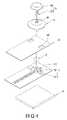
- FIG. 1is a perspective, exposed view of a two-stage button structure according to the present invention
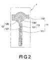
- FIG. 2is a top view of a silver paste PCB of a two-stage button structure according to the present invention
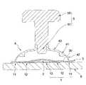
- FIG. 3is a side, cross-sectional view of a two-stage button structure (before the two-stage button structure is pressed) according to the present invention
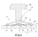
- FIG. 4is a side, cross-sectional view of a two-stage button structure (when the two-stage button structure is pressed to a first stage) according to the present invention.
- FIG. 5is a side, cross-sectional view of a two-stage button structure (when the two-stage button structure is pressed to a second stage) according to the present invention.
- the present inventionprovides a two-stage button structure comprising: a silver paste PCB 1 , a metal dome 2 , a film 3 , a flexible contact body 4 , a button body 5 , and a frame 6 that is disposed under the silver paste PCB 1 .
- the silver paste PCB 1has a first conductive area 11 , a second conductive area 12 and a third conductive area 13 that are separated from each other and are sequentially formed thereon from inside to outside.
- the third conductive area 13has a circular area 130 formed under the metal dome 2 , and a third striped area 131 connected with the circular area 130 .
- the second conductive area 12has a second surrounding area 120 formed along the circular area 130 , and a second striped area 121 connected with the second surrounding area 120 and formed along one side of the third stripe 131 .
- the first conductive area 11has a first surrounding area 110 formed along the second surrounding area 120 , and a first striped area 111 connected with the first surrounding area 110 and formed along another side of the third stripe 131 .
- the metal dome 2is electrically disposed on the second conductive area 12 and is insulated from the third conductive area 13 .
- the film 3is disposed on the silver paste PCB 1 and is covered on the metal dome 2 .
- the film 3has a pair of through holes 30 for respectively exposing one part of the first conductive area 11 and one part of the second conductive area 12 .
- the flexible contact body 4has an opening 40 , and a pair of conductive blocks 41 projected downwardly therefrom and corresponding to the pair of through holes 30 .
- the flexible contact body 4can be made of rubber or any flexible material.
- the pair of conductive blocks 41can be a pair of conductive rubbers.
- the flexible contact body 4has a first deformed area 42 and a second deformed area 43 formed on the first deformed area 42 .
- the first deformed area 42has a thickness smaller than that of the second deformed area 43 . In other words; the loading capability of the first deformed area 42 is smaller than that of the second deformed area 43 .
- the first deformed area 42is deformed easier than the second deformed area 43 . Therefore, when the flexible contact body 4 bears pressure, the first deformed area 42 will be the first to become deformed.
- the button body 5has a pressing portion 50 and a contact pin 51 extending downwardly from the pressing portion 50 .
- the button body 5is disposed on the flexible contact body 4 and the contact pin 51 passes through the opening 40 .
- a level position of the contact pin 51is higher than that of the pair of conductive blocks 41 .
- the first, the second and the third conductive areas 11 , 12 , 13are insulate from each other.
- the pair of conductive blocks 41 of the flexible contact body 4respectively pass through the pair of through holes 30 of the film 3 to respectively electrically contact the first conductive area 11 and the second conductive area 12 for generating a first stage signal.
- the metal dome 5is pressed via the contact pin 51 to touch the third conductive area 13 and the pair of conductive blocks 41 respectively electrically contact the first conductive area 11 and the second conductive area 12 at the same time (meaning that the first conductive area 11 and the second conductive area 12 maintain electrical contact) so that the second conductive area 12 and the third conductive area 13 electrically connect each other to generate a second stage signal.
- the combination of the silver paste PCB 1 and the metal dome 2is used to replace the known thick PCB.
- the flexible contact body 4flexible rubber body
- the button body 5are combined together for achieving a two-stage pressing function.
- the two-stage button structureis composed of the silver paste PCB 1 , the metal dome 2 , the flexible contact body 4 , and the button body 5 , its manufacturing cost is cheap.
- the width of the combination of the silver paste PCB 1 and the metal dome 2is thin, so that the design space of the combination of the silver paste PCB 1 and the metal dome 2 is less than that of the known combination of the PCB and the switch.
Landscapes
- Push-Button Switches (AREA)
Abstract
Description
1. Field of the Invention
The present invention relates to a button structure, and particularly relates to a two-stage button structure that has a two-stage signal output function.
2. Description of the Related Art
There are many methods for people to commemorate an occasion. One common way is by taking pictures, because any occasion such as travel, a celebration, an event, or any good time that deserves to be commemorated can be recorded via a camera. Moreover, it is convenient for users to transmit image data from a camera to an electronic device such as a computer for modifying the image data. In addition, the price of a digital camera has become increasingly cheaper, so the number of people using digital cameras increases day by day.
In general a shutter button with a focusing function has two-stage pressing functions. The first stage pressing function (pressing lightly) is for focusing and the second stage pressing function (pressing to the end) is for taking a picture. The known two-stage button structure includes: a PCB, a switch mounted on the PCB, and a button element disposed on the switch. In addition, the button element has a button body and a spring disposed under the button body.
Hence, the known two-stage button structure is composed of the PCB, the switch, and the button element that includes the button body and the spring. Therefore, the assembly of the known two-stage button structure involves too many parts and increases the overall cost of the camera. Moreover, the thickness of the combination of the PCB and the switch is large, so that the known two-stage button structure needs a larger design space.
The present invention provides a two-stage button structure. The two-stage button structure has a silver paste PCB and a metal dome for replacing the known thick PCB. The two-stage button structure also has a flexible rubber body and a button body combined together for achieving a two-stage pressing function.
Furthermore, because the two-stage button structure is composed of the silver paste PCB, the metal dome, the flexible rubber body, and the button body, its manufacture cost is cheaper than the prior art. In addition, the width of the combination of the silver paste PCB and the metal dome is thinner than the prior art, so the design space of the combination of the silver paste PCB and the metal dome can be smaller than that of the known combination of the PCB and the switch.
One aspect of the present invention is a two-stage button structure, comprising: a silver paste PCB, a metal dome, a flexible contact body, and a button body. The silver paste PCB has a first conductive area, a second conductive area and a third conductive area that are separated from each other and are sequentially formed thereon from inside to outside. The metal dome is electrically disposed on the second conductive area, and is insulated from the third conductive area.
Moreover, the film is disposed on the silver paste PCB and is covered on the metal dome. The film has a pair of through holes for respectively exposing one part of the first conductive area and one part of the second conductive area. The flexible contact body has an opening, and a pair of conductive blocks projected downwardly therefrom and corresponding to the pair of through holes. The button body has a pressing portion and a contact pin extending downwardly from the pressing portion. The button body is disposed on the flexible contact body and the contact pin passes through the opening.
Whereby, when the button body is pressed to the first stage, the pair of conductive blocks of the flexible contact body respectively pass through the pair of through holes of the film to respectively electrically contact the first and the second conductive areas for generating a first stage signal. When the button body is pressed to the second stage, the metal dome is pressed via the contact pin to touch the third conductive area and the pair of conductive blocks respectively electrically contact the first and the second conductive areas at the same time so that the second and the third conductive areas electrically connect each other to generate a second stage signal.
It is to be understood that both the foregoing general description and the following detailed description are exemplary, and are intended to provide further explanation of the invention as claimed. Other advantages and features of the invention will be apparent from the following description, drawings and claims.
The various objects and advantages of the present invention will be more readily understood from the following detailed description when read in conjunction with the appended drawings, in which:
Referring toFIGS. 1 and 2 , the present invention provides a two-stage button structure comprising: asilver paste PCB 1, ametal dome 2, afilm 3, aflexible contact body 4, abutton body 5, and aframe 6 that is disposed under thesilver paste PCB 1.
Thesilver paste PCB 1 has a firstconductive area 11, a secondconductive area 12 and a thirdconductive area 13 that are separated from each other and are sequentially formed thereon from inside to outside. The thirdconductive area 13 has acircular area 130 formed under themetal dome 2, and a thirdstriped area 131 connected with thecircular area 130. Moreover, the secondconductive area 12 has a second surroundingarea 120 formed along thecircular area 130, and a secondstriped area 121 connected with the second surroundingarea 120 and formed along one side of thethird stripe 131. In addition, the firstconductive area 11 has a first surroundingarea 110 formed along the second surroundingarea 120, and a firststriped area 111 connected with the first surroundingarea 110 and formed along another side of thethird stripe 131.
Themetal dome 2 is electrically disposed on the secondconductive area 12 and is insulated from the thirdconductive area 13. Thefilm 3 is disposed on thesilver paste PCB 1 and is covered on themetal dome 2. Thefilm 3 has a pair of throughholes 30 for respectively exposing one part of the firstconductive area 11 and one part of the secondconductive area 12.
Theflexible contact body 4 has anopening 40, and a pair ofconductive blocks 41 projected downwardly therefrom and corresponding to the pair of throughholes 30. Theflexible contact body 4 can be made of rubber or any flexible material. Hence, the pair ofconductive blocks 41 can be a pair of conductive rubbers. Theflexible contact body 4 has a firstdeformed area 42 and a seconddeformed area 43 formed on the firstdeformed area 42. The firstdeformed area 42 has a thickness smaller than that of the seconddeformed area 43. In other words; the loading capability of the firstdeformed area 42 is smaller than that of the seconddeformed area 43. Hence, the first deformedarea 42 is deformed easier than the seconddeformed area 43. Therefore, when theflexible contact body 4 bears pressure, the firstdeformed area 42 will be the first to become deformed.
Thebutton body 5 has apressing portion 50 and acontact pin 51 extending downwardly from thepressing portion 50. Thebutton body 5 is disposed on theflexible contact body 4 and thecontact pin 51 passes through the opening40. In addition, a level position of thecontact pin 51 is higher than that of the pair ofconductive blocks 41.
Referring toFIGS. 3–5 , before thebutton body 5 is pressed, the first, the second and the thirdconductive areas
When thebutton body 5 is pressed to a first stage (as shown inFIG. 4 ), the pair ofconductive blocks 41 of theflexible contact body 4 respectively pass through the pair of throughholes 30 of thefilm 3 to respectively electrically contact the firstconductive area 11 and the secondconductive area 12 for generating a first stage signal.
When thebutton body 5 is pressed to a second stage (as shown inFIG. 5 ), themetal dome 5 is pressed via thecontact pin 51 to touch the thirdconductive area 13 and the pair ofconductive blocks 41 respectively electrically contact the firstconductive area 11 and the secondconductive area 12 at the same time (meaning that the firstconductive area 11 and the secondconductive area 12 maintain electrical contact) so that the secondconductive area 12 and the thirdconductive area 13 electrically connect each other to generate a second stage signal.
In conclusion, the combination of thesilver paste PCB 1 and themetal dome 2 is used to replace the known thick PCB. Moreover, the flexible contact body4 (flexible rubber body) and thebutton body 5 are combined together for achieving a two-stage pressing function.
Furthermore, because the two-stage button structure is composed of thesilver paste PCB 1, themetal dome 2, theflexible contact body 4, and thebutton body 5, its manufacturing cost is cheap. The width of the combination of thesilver paste PCB 1 and themetal dome 2 is thin, so that the design space of the combination of thesilver paste PCB 1 and themetal dome 2 is less than that of the known combination of the PCB and the switch.
Although the present invention has been described with reference to the preferred best molds thereof, it will be understood that the invention is not limited to the details thereof. Various substitutions and modifications have been suggested in the foregoing description, and others will occur to those of ordinary skill in the art. Therefore, all such substitutions and modifications are intended to be embraced within the scope of the invention as defined in the appended claims.
Claims (10)
1. A two-stage button structure, comprising:
a silver paste PCB having a first conductive area, a second conductive area and a third conductive area that are separated from each other and are sequentially formed thereon from outside to inside;
a metal dome electrically disposed on the second conductive area, and insulated from the third conductive area;
a film disposed on the silver paste PCB and covered on the metal dome, wherein the film has a pair of through holes for respectively exposing one part of the first conductive area and one part of the second conductive area;
a flexible contact body having an opening, and a pair of conductive blocks projected downwardly therefrom and corresponding to the pair of through holes; and
a button body having a pressing portion and a contact pin extending downwardly from the pressing portion, wherein the button body is disposed on the flexible contact body and the contact pin passes through the opening;
whereby, when the button body is pressed to a first stage, the pair of conductive blocks of the flexible contact body respectively pass through the pair of through holes of the film to respectively electrically contact the first and the second conductive areas for generating a first stage signal; when the button body is pressed to a second stage, the metal dome is pressed via the contact pin to touch the third conductive area and the pair of conductive blocks respectively electrically contact the first and the second conductive areas at the same time so that the second and the third conductive areas electrically connect with each other to generate a second stage signal.
2. The two-stage button structure as claimed inclaim 1 , further comprising a frame disposed under the silver paste PCB.
3. The two-stage button structure as claimed inclaim 1 , wherein the third conductive area has a circular area formed under the metal dome, and a third striped area connected with the circular area.
4. The two-stage button structure as claimed inclaim 3 , wherein the second conductive area has a second surrounding area formed along the circular area, and a second striped area connected with the second surrounding area and formed along one side of the third stripe.
5. The two-stage button structure as claimed inclaim 4 , wherein the first conductive area has a first surrounding area formed along the second surrounding area, and a first striped area connected with the first surrounding area and formed along another side of the third stripe.
6. The two-stage button structure as claimed inclaim 1 , wherein the flexible contact body has a first deformed area and a second deformed area formed on the first deformed area.
7. The two-stage button structure as claimed inclaim 6 , wherein the first deformed area has a thickness smaller than that of the second deformed area.
8. The two-stage button structure as claimed inclaim 1 , wherein the flexible contact body is made of rubber.
9. The two-stage button structure as claimed inclaim 1 , wherein the pair of conductive blocks is a pair of conductive rubbers.
10. The two-stage button structure as claimed inclaim 1 , wherein a level position of the contact pin is higher than that of the pair of conductive blocks.
Priority Applications (1)
| Application Number | Priority Date | Filing Date | Title |
|---|---|---|---|
| US11/580,089US7217893B1 (en) | 2006-10-13 | 2006-10-13 | Two-stage button structure |
Applications Claiming Priority (1)
| Application Number | Priority Date | Filing Date | Title |
|---|---|---|---|
| US11/580,089US7217893B1 (en) | 2006-10-13 | 2006-10-13 | Two-stage button structure |
Publications (1)
| Publication Number | Publication Date |
|---|---|
| US7217893B1true US7217893B1 (en) | 2007-05-15 |
Family
ID=38015714
Family Applications (1)
| Application Number | Title | Priority Date | Filing Date |
|---|---|---|---|
| US11/580,089ActiveUS7217893B1 (en) | 2006-10-13 | 2006-10-13 | Two-stage button structure |
Country Status (1)
| Country | Link |
|---|---|
| US (1) | US7217893B1 (en) |
Cited By (41)
| Publication number | Priority date | Publication date | Assignee | Title |
|---|---|---|---|---|
| US20070152042A1 (en)* | 2005-10-21 | 2007-07-05 | Jon Mittler | Protective cover for terminal keypad security switches |
| US20070151833A1 (en)* | 2005-12-29 | 2007-07-05 | Hon Hai Precision Ind. Co., Ltd. | Multi-direction switch |
| US20070184877A1 (en)* | 2006-02-06 | 2007-08-09 | Lg Electronic Inc. | Mobile terminal key input device and method |
| US20070221483A1 (en)* | 2006-03-22 | 2007-09-27 | Nokia Corporation | Multi-functional touch actuator in electronic devices |
| US20080023311A1 (en)* | 2006-07-26 | 2008-01-31 | Altek Corporation | Key structure |
| US20090050462A1 (en)* | 2007-08-24 | 2009-02-26 | Freudenberg-Nok General Partnership | Integrated conductive radio button |
| US20100000847A1 (en)* | 2006-10-03 | 2010-01-07 | Abatek International Ag | Key for SMT Applications |
| US20100084251A1 (en)* | 2008-10-08 | 2010-04-08 | Research In Motion Limited | Dual-action single-key mechanism |
| US20100084252A1 (en)* | 2008-10-08 | 2010-04-08 | Research In Motion Limited | Two-stage switch assembly |
| US20110036701A1 (en)* | 2009-08-17 | 2011-02-17 | Yung-Hui Wang | Closed-air cushioned key switch structure |
| US7952038B1 (en) | 2009-12-04 | 2011-05-31 | Shin-Etsu Polymer Co., Ltd. | Two-stage switch apparatus |
| US20110203912A1 (en)* | 2010-02-24 | 2011-08-25 | Apple Inc. | Stacked metal and elastomeric dome for key switch |
| US20120067711A1 (en)* | 2010-09-16 | 2012-03-22 | Hon Hai Precision Industry Co., Ltd. | Electronic device having waterproof button |
| US8742269B2 (en) | 2008-11-06 | 2014-06-03 | Covidien Ag | Two-stage switch for surgical device |
| US8992555B2 (en) | 2007-12-03 | 2015-03-31 | Covidien Ag | Method of assembling a cordless hand-held ultrasonic cautery cutting device |
| US9017355B2 (en) | 2007-12-03 | 2015-04-28 | Covidien Ag | Battery-powered hand-held ultrasonic surgical cautery cutting device |
| US20150170854A1 (en)* | 2013-12-13 | 2015-06-18 | Fujitsu Component Limited | Key switch device and keyboard |
| US9107690B2 (en) | 2007-12-03 | 2015-08-18 | Covidien Ag | Battery-powered hand-held ultrasonic surgical cautery cutting device |
| US20150279590A1 (en)* | 2014-03-27 | 2015-10-01 | Samsung Electronics Co., Ltd. | Electronic device having input button |
| US9314261B2 (en) | 2007-12-03 | 2016-04-19 | Covidien Ag | Battery-powered hand-held ultrasonic surgical cautery cutting device |
| US9711303B2 (en) | 2013-06-27 | 2017-07-18 | Blackberry Limited | Dome-shaped assembly and handheld electronic device including dome-shaped assembly |
| US20190100178A1 (en)* | 2017-09-29 | 2019-04-04 | Mando Corporation | Pressure sensor and electronic control brake system for vehicle having the same |
| US10368898B2 (en) | 2016-05-05 | 2019-08-06 | Covidien Lp | Ultrasonic surgical instrument |
| US10426508B2 (en) | 2007-12-03 | 2019-10-01 | Covidien Ag | Cordless hand-held ultrasonic cautery device |
| US10582944B2 (en) | 2018-02-23 | 2020-03-10 | Covidien Lp | Ultrasonic surgical instrument with torque assist feature |
| CN112204690A (en)* | 2018-05-29 | 2021-01-08 | 阿尔卑斯阿尔派株式会社 | push switch |
| US11004627B2 (en) | 2017-03-30 | 2021-05-11 | Fujitsu Component Limited | Reaction force generating member and key switch device |
| US11127543B2 (en) | 2017-09-08 | 2021-09-21 | Sateco Ag | Button assembly governed by a restrictor member |
| US11229449B2 (en) | 2018-02-05 | 2022-01-25 | Covidien Lp | Ultrasonic horn, ultrasonic transducer assembly, and ultrasonic surgical instrument including the same |
| US11246617B2 (en) | 2018-01-29 | 2022-02-15 | Covidien Lp | Compact ultrasonic transducer and ultrasonic surgical instrument including the same |
| US11246621B2 (en) | 2018-01-29 | 2022-02-15 | Covidien Lp | Ultrasonic transducers and ultrasonic surgical instruments including the same |
| US11259832B2 (en) | 2018-01-29 | 2022-03-01 | Covidien Lp | Ultrasonic horn for an ultrasonic surgical instrument, ultrasonic surgical instrument including the same, and method of manufacturing an ultrasonic horn |
| US11478268B2 (en) | 2019-08-16 | 2022-10-25 | Covidien Lp | Jaw members for surgical instruments and surgical instruments incorporating the same |
| US11617599B2 (en) | 2020-10-15 | 2023-04-04 | Covidien Lp | Ultrasonic surgical instrument |
| US11666357B2 (en) | 2019-09-16 | 2023-06-06 | Covidien Lp | Enclosure for electronics of a surgical instrument |
| US11717312B2 (en) | 2021-10-01 | 2023-08-08 | Covidien Lp | Surgical system including blade visualization markings |
| US11862415B2 (en) | 2013-05-14 | 2024-01-02 | Fujitsu Component Limited | Keyswitch device and keyboard |
| US12004769B2 (en) | 2020-05-20 | 2024-06-11 | Covidien Lp | Ultrasonic transducer assembly for an ultrasonic surgical instrument |
| US12020873B2 (en) | 2021-10-27 | 2024-06-25 | Darfon Electronics Corp. | Sensing keyboard and sensing keyswitches thereof |
| US12023065B2 (en) | 2019-09-03 | 2024-07-02 | Covidien Lp | Bi-stable spring-latch connector for ultrasonic surgical instruments |
| US12426912B2 (en) | 2021-06-17 | 2025-09-30 | Covidien Lp | Surgical instruments, systems, and methods for frequency dithering control functionality |
Citations (7)
| Publication number | Priority date | Publication date | Assignee | Title |
|---|---|---|---|---|
| US4659881A (en)* | 1986-01-27 | 1987-04-21 | Eastman Kodak Company | Multidome multistage switch assembly |
| US5510584A (en)* | 1995-03-07 | 1996-04-23 | Itt Corporation | Sequentially operated snap action membrane switches |
| US6303887B1 (en)* | 2001-02-23 | 2001-10-16 | Shin-Etsu Polymer Co., Ltd. | Pushbutton switch element for pushbutton switch structure |
| US6936777B1 (en)* | 2004-03-12 | 2005-08-30 | Fuji Electronics Industries Co., Ltd. | Two-step switch |
| US6995324B2 (en)* | 2004-04-21 | 2006-02-07 | Hosiden Corporation | Push-on switch |
| US7157650B2 (en)* | 2003-09-09 | 2007-01-02 | Itt Manufacturing Enterprises, Inc. | Electrical switch device with lateral activation |
| US7166813B2 (en)* | 2004-11-30 | 2007-01-23 | Alps Electric Co., Ltd. | Multistep switch having capacitive type sensor |
- 2006
- 2006-10-13USUS11/580,089patent/US7217893B1/enactiveActive
Patent Citations (7)
| Publication number | Priority date | Publication date | Assignee | Title |
|---|---|---|---|---|
| US4659881A (en)* | 1986-01-27 | 1987-04-21 | Eastman Kodak Company | Multidome multistage switch assembly |
| US5510584A (en)* | 1995-03-07 | 1996-04-23 | Itt Corporation | Sequentially operated snap action membrane switches |
| US6303887B1 (en)* | 2001-02-23 | 2001-10-16 | Shin-Etsu Polymer Co., Ltd. | Pushbutton switch element for pushbutton switch structure |
| US7157650B2 (en)* | 2003-09-09 | 2007-01-02 | Itt Manufacturing Enterprises, Inc. | Electrical switch device with lateral activation |
| US6936777B1 (en)* | 2004-03-12 | 2005-08-30 | Fuji Electronics Industries Co., Ltd. | Two-step switch |
| US6995324B2 (en)* | 2004-04-21 | 2006-02-07 | Hosiden Corporation | Push-on switch |
| US7166813B2 (en)* | 2004-11-30 | 2007-01-23 | Alps Electric Co., Ltd. | Multistep switch having capacitive type sensor |
Cited By (70)
| Publication number | Priority date | Publication date | Assignee | Title |
|---|---|---|---|---|
| US20070152042A1 (en)* | 2005-10-21 | 2007-07-05 | Jon Mittler | Protective cover for terminal keypad security switches |
| US7832628B2 (en)* | 2005-10-21 | 2010-11-16 | Verifone, Inc. | Protective cover for terminal keypad security switches |
| US20070151833A1 (en)* | 2005-12-29 | 2007-07-05 | Hon Hai Precision Ind. Co., Ltd. | Multi-direction switch |
| US7737373B2 (en)* | 2006-02-06 | 2010-06-15 | Lg Electronics Inc. | Mobile terminal key input device and method |
| US20070184877A1 (en)* | 2006-02-06 | 2007-08-09 | Lg Electronic Inc. | Mobile terminal key input device and method |
| US7402764B2 (en)* | 2006-03-22 | 2008-07-22 | Nokia Corporation | Multi-functional touch actuator in electronic devices |
| US20070221483A1 (en)* | 2006-03-22 | 2007-09-27 | Nokia Corporation | Multi-functional touch actuator in electronic devices |
| US20080023311A1 (en)* | 2006-07-26 | 2008-01-31 | Altek Corporation | Key structure |
| US7470869B2 (en)* | 2006-07-26 | 2008-12-30 | Altek Corporation | Key structure |
| US20100000847A1 (en)* | 2006-10-03 | 2010-01-07 | Abatek International Ag | Key for SMT Applications |
| US8148657B2 (en)* | 2006-10-03 | 2012-04-03 | Abatek International Ag | Key for SMT applications |
| US20090050462A1 (en)* | 2007-08-24 | 2009-02-26 | Freudenberg-Nok General Partnership | Integrated conductive radio button |
| US7498537B1 (en) | 2007-08-24 | 2009-03-03 | Freudenberg-Nok General Partnership | Integrated conductive radio button |
| US9107690B2 (en) | 2007-12-03 | 2015-08-18 | Covidien Ag | Battery-powered hand-held ultrasonic surgical cautery cutting device |
| US11478820B2 (en) | 2007-12-03 | 2022-10-25 | Covidien Ag | Battery-powered hand-held ultrasonic surgical cautery cutting device |
| US9314261B2 (en) | 2007-12-03 | 2016-04-19 | Covidien Ag | Battery-powered hand-held ultrasonic surgical cautery cutting device |
| US9017355B2 (en) | 2007-12-03 | 2015-04-28 | Covidien Ag | Battery-powered hand-held ultrasonic surgical cautery cutting device |
| US10456158B2 (en) | 2007-12-03 | 2019-10-29 | Covidien Ag | Cordless hand-held ultrasonic surgical device |
| US10426508B2 (en) | 2007-12-03 | 2019-10-01 | Covidien Ag | Cordless hand-held ultrasonic cautery device |
| US8992555B2 (en) | 2007-12-03 | 2015-03-31 | Covidien Ag | Method of assembling a cordless hand-held ultrasonic cautery cutting device |
| US10799913B2 (en) | 2007-12-03 | 2020-10-13 | Covidien Lp | Battery-powered hand-held ultrasonic surgical cautery cutting device |
| US9872696B2 (en) | 2007-12-03 | 2018-01-23 | Covidien Ag | Battery-powered hand-held ultrasonic surgical cautery cutting device |
| US8378240B2 (en) | 2008-10-08 | 2013-02-19 | Research In Motion Limited | Two-stage switch assembly |
| US8227714B2 (en) | 2008-10-08 | 2012-07-24 | Research In Motion Limited | Two-stage switch mounting assembly |
| US8058571B2 (en)* | 2008-10-08 | 2011-11-15 | Research In Motion Limited | Dual-action single-key mechanism |
| US20110233041A1 (en)* | 2008-10-08 | 2011-09-29 | Vijai Rajagopal | Two-Stage Switch Assembly |
| US7977587B2 (en)* | 2008-10-08 | 2011-07-12 | Research In Motion Limited | Two-stage switch assembly |
| US20100084252A1 (en)* | 2008-10-08 | 2010-04-08 | Research In Motion Limited | Two-stage switch assembly |
| US20100084251A1 (en)* | 2008-10-08 | 2010-04-08 | Research In Motion Limited | Dual-action single-key mechanism |
| US8742269B2 (en) | 2008-11-06 | 2014-06-03 | Covidien Ag | Two-stage switch for surgical device |
| US20110036701A1 (en)* | 2009-08-17 | 2011-02-17 | Yung-Hui Wang | Closed-air cushioned key switch structure |
| US20110132732A1 (en)* | 2009-12-04 | 2011-06-09 | Shin-Etsu Polymer Co., Ltd. | Two-stage switch apparatus |
| US7952038B1 (en) | 2009-12-04 | 2011-05-31 | Shin-Etsu Polymer Co., Ltd. | Two-stage switch apparatus |
| US20110203912A1 (en)* | 2010-02-24 | 2011-08-25 | Apple Inc. | Stacked metal and elastomeric dome for key switch |
| US9012795B2 (en)* | 2010-02-24 | 2015-04-21 | Apple Inc. | Stacked metal and elastomeric dome for key switch |
| US20120067711A1 (en)* | 2010-09-16 | 2012-03-22 | Hon Hai Precision Industry Co., Ltd. | Electronic device having waterproof button |
| US11862415B2 (en) | 2013-05-14 | 2024-01-02 | Fujitsu Component Limited | Keyswitch device and keyboard |
| US9711303B2 (en) | 2013-06-27 | 2017-07-18 | Blackberry Limited | Dome-shaped assembly and handheld electronic device including dome-shaped assembly |
| US9741507B2 (en)* | 2013-12-13 | 2017-08-22 | Fujitsu Component Limited | Key switch device and keyboard |
| US10410806B2 (en) | 2013-12-13 | 2019-09-10 | Fujitsu Component Limited | Reaction force generating member for a key switch device |
| US20150170854A1 (en)* | 2013-12-13 | 2015-06-18 | Fujitsu Component Limited | Key switch device and keyboard |
| CN107134386A (en)* | 2013-12-13 | 2017-09-05 | 富士通电子零件有限公司 | Reaction force produces component |
| US11011329B2 (en) | 2013-12-13 | 2021-05-18 | Fujitsu Component Limited | Reaction force generating member for a key switch device |
| US20150279590A1 (en)* | 2014-03-27 | 2015-10-01 | Samsung Electronics Co., Ltd. | Electronic device having input button |
| US9640345B2 (en)* | 2014-03-27 | 2017-05-02 | Samsung Electronics Co., Ltd | Electronic device having input button |
| US10368898B2 (en) | 2016-05-05 | 2019-08-06 | Covidien Lp | Ultrasonic surgical instrument |
| US11266432B2 (en) | 2016-05-05 | 2022-03-08 | Covidien Lp | Ultrasonic surgical instrument |
| US11355293B2 (en) | 2017-03-30 | 2022-06-07 | Fujitsu Component Limited | Reaction force generating member and key switch device |
| US11004627B2 (en) | 2017-03-30 | 2021-05-11 | Fujitsu Component Limited | Reaction force generating member and key switch device |
| US11127543B2 (en) | 2017-09-08 | 2021-09-21 | Sateco Ag | Button assembly governed by a restrictor member |
| CN109572657A (en)* | 2017-09-29 | 2019-04-05 | 株式会社万都 | Pressure sensor and the vehicle electronic control formula braking system for having the sensor |
| US20190100178A1 (en)* | 2017-09-29 | 2019-04-04 | Mando Corporation | Pressure sensor and electronic control brake system for vehicle having the same |
| US11246617B2 (en) | 2018-01-29 | 2022-02-15 | Covidien Lp | Compact ultrasonic transducer and ultrasonic surgical instrument including the same |
| US11246621B2 (en) | 2018-01-29 | 2022-02-15 | Covidien Lp | Ultrasonic transducers and ultrasonic surgical instruments including the same |
| US11259832B2 (en) | 2018-01-29 | 2022-03-01 | Covidien Lp | Ultrasonic horn for an ultrasonic surgical instrument, ultrasonic surgical instrument including the same, and method of manufacturing an ultrasonic horn |
| US12150665B2 (en) | 2018-01-29 | 2024-11-26 | Covidien Lp | Compact ultrasonic transducer and ultrasonic surgical instrument including the same |
| US11229449B2 (en) | 2018-02-05 | 2022-01-25 | Covidien Lp | Ultrasonic horn, ultrasonic transducer assembly, and ultrasonic surgical instrument including the same |
| US11304721B2 (en) | 2018-02-23 | 2022-04-19 | Covidien Lp | Ultrasonic surgical instrument with torque assist feature |
| US10582944B2 (en) | 2018-02-23 | 2020-03-10 | Covidien Lp | Ultrasonic surgical instrument with torque assist feature |
| CN112204690A (en)* | 2018-05-29 | 2021-01-08 | 阿尔卑斯阿尔派株式会社 | push switch |
| CN112204690B (en)* | 2018-05-29 | 2023-10-20 | 阿尔卑斯阿尔派株式会社 | push switch |
| US11309143B2 (en)* | 2018-05-29 | 2022-04-19 | Alps Alpine Co., Ltd. | Push switch |
| US11478268B2 (en) | 2019-08-16 | 2022-10-25 | Covidien Lp | Jaw members for surgical instruments and surgical instruments incorporating the same |
| US12023065B2 (en) | 2019-09-03 | 2024-07-02 | Covidien Lp | Bi-stable spring-latch connector for ultrasonic surgical instruments |
| US11666357B2 (en) | 2019-09-16 | 2023-06-06 | Covidien Lp | Enclosure for electronics of a surgical instrument |
| US12004769B2 (en) | 2020-05-20 | 2024-06-11 | Covidien Lp | Ultrasonic transducer assembly for an ultrasonic surgical instrument |
| US11617599B2 (en) | 2020-10-15 | 2023-04-04 | Covidien Lp | Ultrasonic surgical instrument |
| US12426912B2 (en) | 2021-06-17 | 2025-09-30 | Covidien Lp | Surgical instruments, systems, and methods for frequency dithering control functionality |
| US11717312B2 (en) | 2021-10-01 | 2023-08-08 | Covidien Lp | Surgical system including blade visualization markings |
| US12020873B2 (en) | 2021-10-27 | 2024-06-25 | Darfon Electronics Corp. | Sensing keyboard and sensing keyswitches thereof |
Similar Documents
| Publication | Publication Date | Title |
|---|---|---|
| US7217893B1 (en) | Two-stage button structure | |
| US6180903B1 (en) | Tact Switch | |
| CN106534655A (en) | Camera module and mobile terminal | |
| US8071897B2 (en) | Key structure | |
| US10354815B2 (en) | Push switch | |
| JP2009266700A (en) | Push-operation type electronic component and push-switch | |
| JP2005353563A (en) | Switch module for cellular phone | |
| US20050001822A1 (en) | Resilient switch contact for a key switch device | |
| JP2003297175A (en) | Push-on switch | |
| US7279650B2 (en) | Electronic apparatus having illumination button | |
| US20070151833A1 (en) | Multi-direction switch | |
| US20050261019A1 (en) | Mobile terminal for preventing static and method thereof | |
| JP2011134513A (en) | Two-step switch and imaging device with the same | |
| CN101131525B (en) | Two-stage pressing structure | |
| JPH11232962A (en) | Push-on switch | |
| JP2009021106A (en) | Electronics | |
| CN117581322A (en) | Push button switch | |
| US7773958B2 (en) | Key pad assembly and mobile communication terminal having the same | |
| JP2022043622A (en) | Push switch | |
| JP4649393B2 (en) | Horizontal push type 2-stage operation switch | |
| JP4271837B2 (en) | Double push button | |
| JP2000030562A (en) | Panel switch | |
| JP2004333871A (en) | Waterproof construction for electronic equipment, and waterproof camera | |
| JP4310730B2 (en) | Battery terminal connection device for electronic equipment | |
| JP2001195946A (en) | Long stroke type small push button switch for board mounting |
Legal Events
| Date | Code | Title | Description |
|---|---|---|---|
| AS | Assignment | Owner name:ALTEK CORPORATION, TAIWAN Free format text:ASSIGNMENT OF ASSIGNORS INTEREST;ASSIGNORS:HUANG, YU-CHENG;LIN, TZU-CHIH;REEL/FRAME:018421/0861 Effective date:20061012 | |
| STCF | Information on status: patent grant | Free format text:PATENTED CASE | |
| FEPP | Fee payment procedure | Free format text:PAT HOLDER NO LONGER CLAIMS SMALL ENTITY STATUS, ENTITY STATUS SET TO UNDISCOUNTED (ORIGINAL EVENT CODE: STOL); ENTITY STATUS OF PATENT OWNER: LARGE ENTITY | |
| FPAY | Fee payment | Year of fee payment:4 | |
| FPAY | Fee payment | Year of fee payment:8 | |
| MAFP | Maintenance fee payment | Free format text:PAYMENT OF MAINTENANCE FEE, 12TH YEAR, LARGE ENTITY (ORIGINAL EVENT CODE: M1553); ENTITY STATUS OF PATENT OWNER: LARGE ENTITY Year of fee payment:12 | |
| AS | Assignment | Owner name:ALTEK (KUNSHAN) CO., LTD., CHINA Free format text:ASSIGNMENT OF ASSIGNORS INTEREST;ASSIGNOR:ALTEK CORPORATION;REEL/FRAME:057771/0567 Effective date:20210816 |