US7217393B2 - Apparatus and method for process monitoring - Google Patents
Apparatus and method for process monitoringDownload PDFInfo
- Publication number
- US7217393B2 US7217393B2US10/845,767US84576704AUS7217393B2US 7217393 B2US7217393 B2US 7217393B2US 84576704 AUS84576704 AUS 84576704AUS 7217393 B2US7217393 B2US 7217393B2
- Authority
- US
- United States
- Prior art keywords
- flow cell
- measurement chamber
- sample
- measurement
- flow
- Prior art date
- Legal status (The legal status is an assumption and is not a legal conclusion. Google has not performed a legal analysis and makes no representation as to the accuracy of the status listed.)
- Expired - Fee Related
Links
- 238000012544monitoring processMethods0.000titleclaimsabstractdescription44
- 238000000034methodMethods0.000titleclaimsdescription74
- 230000008569processEffects0.000titleclaimsdescription57
- 238000012360testing methodMethods0.000claimsabstractdescription105
- 239000012530fluidSubstances0.000claimsabstractdescription45
- 238000005259measurementMethods0.000claimsdescription164
- 239000000523sampleSubstances0.000claimsdescription143
- 239000003153chemical reaction reagentSubstances0.000claimsdescription47
- 238000006243chemical reactionMethods0.000claimsdescription31
- 239000000463materialSubstances0.000claimsdescription25
- 230000003287optical effectEffects0.000claimsdescription23
- 230000004044responseEffects0.000claimsdescription17
- 238000003556assayMethods0.000claimsdescription16
- 238000012790confirmationMethods0.000claimsdescription14
- 238000012545processingMethods0.000claimsdescription9
- 230000008859changeEffects0.000claimsdescription6
- 230000031700light absorptionEffects0.000claimsdescription6
- 239000000376reactantSubstances0.000claimsdescription6
- 238000009736wettingMethods0.000claimsdescription6
- 238000010521absorption reactionMethods0.000claimsdescription5
- 239000012470diluted sampleSubstances0.000claimsdescription3
- 239000003085diluting agentSubstances0.000claimsdescription3
- 238000010517secondary reactionMethods0.000claimsdescription3
- 238000012806monitoring deviceMethods0.000claims8
- 239000012491analyteSubstances0.000description14
- 210000004369bloodAnatomy0.000description11
- 239000008280bloodSubstances0.000description11
- 238000009534blood testMethods0.000description5
- 102000011022Chorionic GonadotropinHuman genes0.000description4
- 108010062540Chorionic GonadotropinProteins0.000description4
- 229940084986human chorionic gonadotropinDrugs0.000description4
- 238000011017operating methodMethods0.000description4
- 230000000717retained effectEffects0.000description4
- 238000013459approachMethods0.000description3
- 230000008901benefitEffects0.000description3
- 239000000975dyeSubstances0.000description3
- IJGRMHOSHXDMSA-UHFFFAOYSA-NAtomic nitrogenChemical compoundN#NIJGRMHOSHXDMSA-UHFFFAOYSA-N0.000description2
- NIXOWILDQLNWCW-UHFFFAOYSA-Nacrylic acid groupChemical groupC(C=C)(=O)ONIXOWILDQLNWCW-UHFFFAOYSA-N0.000description2
- 230000009286beneficial effectEffects0.000description2
- 210000001124body fluidAnatomy0.000description2
- 239000010839body fluidSubstances0.000description2
- 238000010276constructionMethods0.000description2
- 238000001514detection methodMethods0.000description2
- 239000007789gasSubstances0.000description2
- PCHJSUWPFVWCPO-UHFFFAOYSA-NgoldChemical compound[Au]PCHJSUWPFVWCPO-UHFFFAOYSA-N0.000description2
- 230000002209hydrophobic effectEffects0.000description2
- 238000003018immunoassayMethods0.000description2
- 239000007788liquidSubstances0.000description2
- 239000006193liquid solutionSubstances0.000description2
- 238000004519manufacturing processMethods0.000description2
- 238000012986modificationMethods0.000description2
- 230000004048modificationEffects0.000description2
- 230000035935pregnancyEffects0.000description2
- 238000009597pregnancy testMethods0.000description2
- 239000000126substanceSubstances0.000description2
- 208000035143Bacterial infectionDiseases0.000description1
- 229920002799BoPETPolymers0.000description1
- 102000001554HemoglobinsHuman genes0.000description1
- 108010054147HemoglobinsProteins0.000description1
- 239000005041Mylar™Substances0.000description1
- 206010028980NeoplasmDiseases0.000description1
- 208000036142Viral infectionDiseases0.000description1
- 239000000654additiveSubstances0.000description1
- 239000000853adhesiveSubstances0.000description1
- 230000001070adhesive effectEffects0.000description1
- 208000022362bacterial infectious diseaseDiseases0.000description1
- 230000023555blood coagulationEffects0.000description1
- 201000011510cancerDiseases0.000description1
- 230000003915cell functionEffects0.000description1
- 239000011248coating agentSubstances0.000description1
- 238000000576coating methodMethods0.000description1
- 230000001427coherent effectEffects0.000description1
- 239000003086colorantSubstances0.000description1
- 230000002950deficientEffects0.000description1
- 230000001419dependent effectEffects0.000description1
- 238000002405diagnostic procedureMethods0.000description1
- 238000010586diagramMethods0.000description1
- 208000037265diseases, disorders, signs and symptomsDiseases0.000description1
- 208000035475disorderDiseases0.000description1
- 238000006073displacement reactionMethods0.000description1
- 239000003814drugSubstances0.000description1
- 229940079593drugDrugs0.000description1
- 230000000694effectsEffects0.000description1
- 239000003792electrolyteSubstances0.000description1
- 230000005672electromagnetic fieldEffects0.000description1
- 230000006870functionEffects0.000description1
- 230000002068genetic effectEffects0.000description1
- 238000010438heat treatmentMethods0.000description1
- 230000003054hormonal effectEffects0.000description1
- 238000003384imaging methodMethods0.000description1
- 239000011261inert gasSubstances0.000description1
- 230000002452interceptive effectEffects0.000description1
- 230000014759maintenance of locationEffects0.000description1
- 239000003550markerSubstances0.000description1
- 230000007246mechanismEffects0.000description1
- 239000012528membraneSubstances0.000description1
- 235000020938metabolic statusNutrition0.000description1
- 208000010125myocardial infarctionDiseases0.000description1
- 230000003961neuronal insultEffects0.000description1
- 229910052757nitrogenInorganic materials0.000description1
- 239000002245particleSubstances0.000description1
- 238000012123point-of-care testingMethods0.000description1
- 229920006267polyester filmPolymers0.000description1
- 238000003908quality control methodMethods0.000description1
- 230000009467reductionEffects0.000description1
- 238000005070samplingMethods0.000description1
- 238000001179sorption measurementMethods0.000description1
- 238000010998test methodMethods0.000description1
- 238000002604ultrasonographyMethods0.000description1
- 230000009385viral infectionEffects0.000description1
Images


Classifications
- G—PHYSICS
- G01—MEASURING; TESTING
- G01N—INVESTIGATING OR ANALYSING MATERIALS BY DETERMINING THEIR CHEMICAL OR PHYSICAL PROPERTIES
- G01N33/00—Investigating or analysing materials by specific methods not covered by groups G01N1/00 - G01N31/00
- G01N33/48—Biological material, e.g. blood, urine; Haemocytometers
- G01N33/50—Chemical analysis of biological material, e.g. blood, urine; Testing involving biospecific ligand binding methods; Immunological testing
- G01N33/53—Immunoassay; Biospecific binding assay; Materials therefor
- G01N33/5302—Apparatus specially adapted for immunological test procedures
- G—PHYSICS
- G01—MEASURING; TESTING
- G01N—INVESTIGATING OR ANALYSING MATERIALS BY DETERMINING THEIR CHEMICAL OR PHYSICAL PROPERTIES
- G01N21/00—Investigating or analysing materials by the use of optical means, i.e. using sub-millimetre waves, infrared, visible or ultraviolet light
- G01N21/01—Arrangements or apparatus for facilitating the optical investigation
- G01N21/03—Cuvette constructions
- G01N21/05—Flow-through cuvettes
- G—PHYSICS
- G16—INFORMATION AND COMMUNICATION TECHNOLOGY [ICT] SPECIALLY ADAPTED FOR SPECIFIC APPLICATION FIELDS
- G16H—HEALTHCARE INFORMATICS, i.e. INFORMATION AND COMMUNICATION TECHNOLOGY [ICT] SPECIALLY ADAPTED FOR THE HANDLING OR PROCESSING OF MEDICAL OR HEALTHCARE DATA
- G16H10/00—ICT specially adapted for the handling or processing of patient-related medical or healthcare data
- G16H10/40—ICT specially adapted for the handling or processing of patient-related medical or healthcare data for data related to laboratory analysis, e.g. patient specimen analysis
- Y—GENERAL TAGGING OF NEW TECHNOLOGICAL DEVELOPMENTS; GENERAL TAGGING OF CROSS-SECTIONAL TECHNOLOGIES SPANNING OVER SEVERAL SECTIONS OF THE IPC; TECHNICAL SUBJECTS COVERED BY FORMER USPC CROSS-REFERENCE ART COLLECTIONS [XRACs] AND DIGESTS
- Y10—TECHNICAL SUBJECTS COVERED BY FORMER USPC
- Y10T—TECHNICAL SUBJECTS COVERED BY FORMER US CLASSIFICATION
- Y10T436/00—Chemistry: analytical and immunological testing
- Y10T436/11—Automated chemical analysis
- Y10T436/115831—Condition or time responsive
- Y—GENERAL TAGGING OF NEW TECHNOLOGICAL DEVELOPMENTS; GENERAL TAGGING OF CROSS-SECTIONAL TECHNOLOGIES SPANNING OVER SEVERAL SECTIONS OF THE IPC; TECHNICAL SUBJECTS COVERED BY FORMER USPC CROSS-REFERENCE ART COLLECTIONS [XRACs] AND DIGESTS
- Y10—TECHNICAL SUBJECTS COVERED BY FORMER USPC
- Y10T—TECHNICAL SUBJECTS COVERED BY FORMER US CLASSIFICATION
- Y10T436/00—Chemistry: analytical and immunological testing
- Y10T436/11—Automated chemical analysis
- Y10T436/117497—Automated chemical analysis with a continuously flowing sample or carrier stream
- Y10T436/118339—Automated chemical analysis with a continuously flowing sample or carrier stream with formation of a segmented stream
Definitions
- the present inventionrelates generally to methods and systems for real time process monitoring and, more specifically, to methods and systems for monitoring chemical or biological test process.
- Blood and other body fluid testsare important diagnostic methods in patient care and treatment. The reliability and the accuracy of the tests are critical in correctly diagnosing the patient and administrating proper treatment.
- the Food and Drug Administration (FDA)has established numerous quality standards for the various blood or body fluid tests. Monitoring the test process is beneficial in producing reliable and accurate test results.
- One way of monitoring the test processis periodically performing the monitoring test on standard test samples.
- the monitoring test resultsare compared with expected results to verify the accuracy of the test processes or correct the test instrument or process when appropriate.
- the test processesare assumed to generate consistent result between the monitoring tests.
- test processAnother way of monitoring the test process is including standard test samples in the test process. This approach is suitable for a test process that performs tests on multiple samples. The test results on the standard test samples are compared with expected results to verify the accuracy of the test processes. In this approach, the test processes on real samples are assumed to generate result consistent with those on standard test samples.
- test apparatusit would be advantageous to have an apparatus and a method for monitoring a test process that is continuous, simple, and reliable. It is desirable for the test apparatus to be compact and capable of generating test results fast thereby meeting the need of the emergency rooms. It would be of further advantage for the apparatus and method to be easily adaptable for monitoring different test processes.
- An object of the present inventionis to provide improved methods and systems for monitoring a test processes in real time.
- Another object of the present inventionis to provide methods and systems for monitoring test processes that performs a comparison of a timing of the introduction, and the exit of a sample to and from a measurement chamber, in order to confirm of a point in time of a valid reaction of the sample in the measurement chamber.
- Yet another object of the present inventionis to provide methods and systems for monitoring test processes that directly monitors the flow of a sample and a reagent into a measurement chamber.
- a further object of the present inventionis to provide methods and systems for monitoring test processes in a flow cell that in real time sense the flow a sample or a reagent without relying on information that originates outside the flow cell.
- a flow cellis adapted to be positioned in a flow cell support.
- the flow cellincludes a reaction chamber.
- a monitor devicemonitors and produces a signal that is indicative of an introduction and an exit of a sample to and from the reaction chamber.
- Logic resourcesreceive the signal and perform a comparison of a timing of the introduction and the exit of the sample to and from the reaction chamber. This produces a confirmation of a point in time for a valid reaction of the sample in the reaction chamber.
- An energy sourceproduces an output of energy that interacts with the reaction chamber.
- a sensoris positioned to receive an output from the flow cell.
- a methodfor determining the presence of at least one biological analyte that may be present in a liquid sample.
- An apparatusis provided for testing fluid samples that includes a flow cell with a reaction chamber, a monitor device that directly monitors flow of a sample and a reagent into the reaction chamber, a light source that produces an incident beam directed to the reaction chamber; and a sensor positioned to receive an output beam from the flow cell.
- the liquid sampleis introduced into the flow cell. Flow of a sample and a reagent into the reaction chamber is directly monitored in real time without relying on extrinsic information.
- FIG. 1illustrates an apparatus for performing a test on a fluid sample in accordance with the present invention
- FIG. 2is a flow chart illustrating one embodiment of an overall methodology implemented by logic resources of the present invetion.
- FIG. 3is a flow chart illustrating one embodiment of a cartridge processing procedure implemented by logic resources of the present invention.
- FIG. 4is a flow chart illustrating one embodiment of an immunoassay operating procedure implemented by logic resources of the present invention.
- FIG. 5is a flow chart illustrating one embodiment of a hematology operating procedure implemented by logic resources of the present invention.
- FIGS. 6( a )– 6 ( c )illustrate one embodiment of a flow cell used in a fluid sample test in accordance with the present invention.
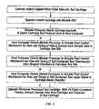
- FIG. 7illustrates a method for monitoring a test process in accordance with the present invention.
- FIG. 1is a schematic diagram of an apparatus 10 for performing a test on a fluid sample in accordance with the present invention.
- apparatus 10is used for performing tests on blood samples.
- the blood testsmay be hematology tests, chemistry tests or immunology tests that provide valuable information in diagnosing such conditions as viral infection, bacterial infection, blood loss, heart attack, pregnancy, hormonal disorders, metabolic status, neuronal damage, cancer, cellular function, genetic information, electrolyte balance, blood clotting and the like.
- apparatus 10is capable of monitoring the blood test process on an effective real time basis without relying on extrinsic information such as the test results of standard samples or secondary process monitoring such as motor position detection.
- Apparatus 10includes a flow cell holder 11 for holding flow cell 12 .
- the sampleflows through flow cell 12 .
- a reactive antibody specific to an analyte in the testis coated on the surface of flow cell 12 during the production of flow cell 12 .
- a new flow cell 12is placed on flow cell holder 11 .
- a sensing of a sample or a reagentis provided in real time without relying on information that originates outside flow cell 12 .
- the external monitoring informationcan include a mechanical, electrical or photo event within apparatus 10 external to flow cell 12 .
- the mechanical informationcan include pump driver movement, valve encoder rotation within apparatus 10 , electrical sensing of a sample in a sampling device such as by a needle or other capillary, and the like.
- in real timemeans a frequency of measurement to insure that the reaction in a selected time period has taken place.
- the selected time periodcan be 10% or less of the overall time period step or process in the reaction.
- in real timecan be in the range of 1 second to 1 minute, and the like, depending on the analyte and process involved.
- Flow cell 12can also include at least one reactive binding partner, including but not limited to an antibody and the like.
- the reactive binding partnercan be any material that can specifically bind the analyte directly or indirectly.
- the reactive antibodycan be present on a surface of flow cell 12 , in a flow path of flow cell 12 (which can be in the form of on a membrane, on particles immobilized in the flow path, and the like.
- the reactive binding partnercan immobilized in a flow path of flow cell 12 .
- Samples and/or reagentsare into flow cell 12 ,
- the reagentcan be a calibrant, a fluid containing reactant, a fluid not containing a reactant, a sample, and the like.
- one or more dyescan be included and mixed with the reactive binding partner. Electrical and other means of sensing can be aided with other non-interfering additives.
- the inclusion of dye base line image data with different characteristicscan be utilized. By way of illustration, and without limitation, the different characteristics can be different in intensity, frequency, magnetic field or other measureable property.
- Apparatus 10also includes an energy source 14 that can be positioned adjacent to flow cell holder 11 A sensor 18 is positioned to receive an output from flow cell 12 .
- Energy source 14can be a variety of different sources including but not limited to electrical, mechanical, optical (both coherent and incoherent light), RF, resistive heating, ultrasound, magnetic, and the like.
- energy source 14can be a LED or LED array. Suitable LED's include but are not limited to, white, red, green, blue source, and the like. An electromagnetic field can also be utilized.
- energy source 14can be positioned to project an incident light beam 15 towards flow cell 12 . In response to the activity in flow cell 12 , a light beam 17 is reflected from flow cell 12 . More than one light source 14 can be used. Multiple light sources 14 can be employed to monitor different test processes using image data formed from different light beams.
- apparatus 10 flow cell 12includes a measurement chamber 19 .
- a monitor device 21directly monitors and produces a signal indicative of an introduction and an exit of at least one of a sample or a reagent to and from measurement chamber 19 .
- Logic resources 23receive the signal and performs a comparison of a timing of the introduction and the exit of the sample to and from measurement chamber 19 . This produces a confirmation of a point in time of a valid reaction of the sample in measurement chamber 19 .
- the validity of the reactionis defined by the juxtapositioning of two or more reagents in a timeframe that has been determined to be sufficient for full and complete reaction.
- Flow cell 12includes an inlet, an outlet and a channel coupled to measurement chamber 19 .
- Inletis configured to provide for introduction of the sample into the inlet by a variety of means including but not limited to, laminar flow, absorption, with the use of a pump, and the like.
- flow cell 12includes bibulous materials 21 . At least a portion of the flow of flow cell 12 can be induced by the bibulous material and is open to the atmosphere.
- Flow cell 12can also include non-bibulous materials 21 .
- the non-bibulous materialsinclude a surface that has measurement chemistry and a second surface that is filled to the first surface. The second surface provides a window 27 viewable by the sensor, optically or electronically.
- sensors 18can be utilized, including but not limited to a, photo sensor, charge coupled device, photo detector or array, PMT, CMOS, and the like.
- Sensor 18can be coupled to a digital image processing circuit. Sensor 18 is used to detect changes of the sample in measurement chamber 19 . Such optical changes include but are not limited to, light reflection characteristics, light absorption characteristics, and light fluorescence characteristics. Electrical changes include but are not limited to conductance, capacitance, impedance, magnetic disturbances, and the like.
- sensor 18is a charge coupled device (CCD) photo detector array coupled to a digital image processing circuit 25 . Sensor 18 may also include a light beam focusing lens in front of the CCD photo detectors 18 .
- CCDcharge coupled device
- Energy source 14produces an output of energy that interacts with measurement chamber 19 .
- Sensor 18is positioned to receive an output from flow cell 12 .
- the outputcan be light intensity, a measurement of wavelength, a measurement of electric capacitance, a measurement of conductivity, impedance and/or magnetic field, and the like.
- Monitor device 21can include energy source 14 and/or sensor 18 .
- Monitor device 21can directly monitor a progress of events inside measurement chamber 19 .
- This progress of events in measurement chamber 19includes but is not limited to, sample introduction, calibrant introduction, sample wash out, calibrant displacement, reagent introduction, and the like.
- the preceding in the prior sentenceoccur in a determined order and timing sequence that is dependent on the assay and sensor type.
- monitor device 21provides an indication of a response of the sample to a mechanical change of apparatus 10 .
- a mechanical changecan include, but is not limited to, movement of a pump to create a flow of sample or reagent, movement of a reaction area in measurement chamber 19 , movement of measurement chamber 19 , a mechanical response relative to a secondary reaction in measurement chamber 19 , and the like.
- monitor device 21detects changes in measurement chamber 19 , and in response to the changes, determines if there is a sufficient amount of at least one of sample, reagent, calibrant, and the like in measurement chamber 19 .
- Logic resources 23can implement a variety of different QC protocols for apparatus 10 , as illustrated in FIGS. 2–5 , including but not limited to, optical measurement to assure wetting of a strip test area at a selected time, optical measurement to assure wetting of a strip test area in measurement chamber 19 at a selected time following application of pressure to a sample pressurization, optical measurement of flow path to assure sample movement to specific point in a flow path at predetermined time from sample pressurization, optical measurement of a flow path to assure sample removal from a specific point in a flow path and replaced by a diluent at a predetermined time from dilutent pressurization, optical measurement of an assay cell in measurement chamber 19 , optical measurement of an assay cell in measurement chamber 19 to assure that diluted sample arrives at a selected measurement region and at a selected time from mixed sample pressurization, electrical measurement of an assay cell to assure that a calibrant has sufficiently filled measurement chamber 19 , electrical measurement of an assay cell to assure that a calibrant has sufficiently filled measurement chamber 19 by
- FIG. 2is a flow chart illustrating an overall methodology of implemented by logic resources 23 .
- FIG. 3is a flow chart illustrating one embodiment of a cartridge processing procedure implemented by logic resources 23 .
- FIG. 4is a flow chart illustrating one embodiment of an immunoassay operating procedure implemented by logic resources 23 .
- FIG. 5is a flow chart illustrating one embodiment of a hematology operating procedure implemented by logic resources 23 .
- logic resourcesprovides instructions that verify the barcode, the cartridge ID and the expiration date, block B.
- sensor 18 with monitor device 21monitors measurement chamber 19 to verify expected changes in electrical, optical properties, and the like.
- logic resources 23provides instructions to compare sensor 18 response to a protocol and provide an indication if all are in an acceptable table range.
- logic resources 23provides instructions to verifiy the barcode at block A, monitor, along with monitor device 21 , each step at block B, and confirm that a correct test protocol was followed at block C.
- logic resources 23provide instructions to verify the patient barcode at block A, verify the cartridge, its expiration date, and that the sample is suitably positioned for sensor 18 at block B, verify sample present in a retention area at block C, verify sample and reagent washout at block D, and verify that a correct protocol sequence and its timing at block E.
- logic resources 23provides instructions to verifiy the patient ID at block A, verify the cartridge, its expiration date, detect the entrance of the sample into a mixing chamber on schedule at block B, detect the introduction of the sample into measurement chamber 19 at block C, verify successive movement of the sample through flow cell 12 at block D, verify adequate light and contrast for imaging quality at block E, and confirm that an overall protocol was followed at block F.
- FIGS. 6( a )– 6 ( c )schematically illustrate flow cell 12 for use in apparatus 10 in performing a test on a fluid sample in accordance with the present invention.
- FIG. 6( a )is a top view of flow cell 12
- FIG. 6( b )is a cross sectional view of flow cell 12 along cross sectional line B—B shown in FIG. 6( a )
- FIG. 6( c )is a cross sectional view of flow cell 12 along cross sectional line C—C shown in FIG. 6( a ).
- flow cell 12is made of transparent (to the sensor used) materials that are chemically inert to the test samples, reactive antibodies, reagents, and wash solution used in the test process.
- Flow cell 12includes a top plate 22 , a bottom plate 24 , and a gasket 26 sandwiched there between.
- top plate 22 and bottom plate 26are made of acrylic
- gasket 26is made of a polyester film, e.g., the film commercially available under the trademark Mylar.
- An adhesivee.g., ultraviolet curable acrylic is used to attach top plate 22 , bottom plate 24 , and gasket 26 together, thereby forming a channel 25 . Openings or apertures are formed in top plate 22 , communicating with channel 25 and serving as an inlet 23 and an outlet 27 , respectively, of flow cell 12 .
- inlet 23 and outlet 27are located adjacent to the two ends of channel 25 .
- a reactive antibody specific to an analyte to be tested using flow cell 12is coated on the walls of channel 25 .
- FIG. 7is a flow chart illustrating a method 100 for monitoring a test process in accordance with the present invention.
- the test processis performed on an apparatus functionally similar to apparatus 10 and flow cell 12 described herein above with reference to FIGS. # 1 and 2 , respectively.
- Flow cell 12has a reactive antibody coated thereon.
- the antibodyis specific to the analyte to be tested.
- the antibodyis immobilized in specific regions on a surface of channel 25 in flow cell 12 during the production of flow cell 12 .
- an antibody specific to human chorionic gonadotropin (hCG)is immobilized by hydrophobic adsorption in predetermined regions on the surface of channel 25 in flow cell 12 .
- hCGhuman chorionic gonadotropin
- the antibodyis not limited to being immobilized through hydrophobic absorption.
- Other means know in the art, either covalent or non-covalent means,can also be used for coating the antibody on flow cell 12 .
- flow cell 12is installed on a test instrument, e.g., apparatus 10 shown in FIG. 1 .
- flow cell 12is installed onto flow cell holder 11 of apparatus 10 .
- flow cell 12is inserted into a test cartridge as shown in the fourth step of FIG. 4 and the test cartridge is installed on the test instrument.
- a step 112light source 14 is turned on, illuminating flow cell 12 with incident light beam 15 .
- the reactive antibody coated in flow cell 12generates reflected light beam 17 .
- photo sensor 18detects reflected light beam 17 .
- the digital image processor in photo sensor 18processes the signal and generates a base line image data of light beam 17 reflected from the antibody coated in flow cell 12 .
- the antibody coated in flow cell 12will generate a uniform white image in photo sensor 18 .
- dyes of various colorsmay be mixed with the antibody to generate base line image data of different characteristics, e.g., different intensities.
- a predetermined amount of sampleis introduced into flow cell 12 .
- the sampleflows into channel 25 of flow cell 12 through inlet 23 as a laminar flow.
- a tube containing the sampleis inserted into a sample dock of a test cartridge. The cartridge is installed on apparatus 10 .
- a pump(not shown in FIG. 1 ) in apparatus 10 pumps the predetermined amount of the sample from the tube, through the cartridge and into inlet 23 of flow cell 12 .
- a low-pressure pumpis preferred in achieving the laminar flow of the sample into flow cell 12 .
- Other mechanismsmay be used to introduce the sample into flow cell 12 .
- the predetermined amount of the samplecan be manually pumped into channel 25 of flow cell 12 through inlet 23 using a pipette.
- the sampleis in contact and reacts with the reactive antibody coated of the surface of channel 25 .
- the validity of the test resultis sensitive to the exposure time of the analyte in the sample to the antibody. Therefore, it is important to closely monitor the time duration of the sample in flow cell 12 to ensure the quality of the test process.
- photo sensor 18detects and processes light beam 17 reflected from the sample in flow cell 12 . Because of different light absorption and reflection characteristics, light beam 17 reflected from the sample in flow cell 12 and detected by photo sensor 18 has different color characteristics than that reflected from the reactive antibody and detected by photo sensor 18 in step 114 . For example, in a blood test, the hemoglobin in blood significantly absorbs blue light. Therefore, the blood sample in flow cell 12 absorbs the light emitted from blue LED light source 14 , thereby resulting a significant reduction in the intensity of reflected light beam 17 . Photo sensor 18 detects a substantially dark image. This dark image indicates the presence of the blood sample in flow cell 12 .
- a wash fluidwhich may be a liquid solution or a gas or airflow is introduced into channel 25 of flow cell 12 through inlet 23 in a step 126 . Displaced by the incoming wash fluid, the sample flows out of channel 25 of flow cell 12 through outlet 27 .
- the wash fluidpreferably cleanses flow cell 12 of all of the sample except a portion of the analyte that has reacted with and is held by the antibody. In example of the blood pregnancy test, the fluid blood is cleansed out of flow cell 12 . However, at least a portion of the hCG in the blood is held by the immobilized antibody coated on surface of channel 25 in flow cell 12 .
- photo sensor 18detects and processes light beam 17 reflected from flow cell 12 . As the sample is washed away from flow cell 12 , the intensity of reflected light beam 17 gradually increases.
- the image data photo sensor 18provides information regarding the efficiency and completeness of the sample wash out process in step 126 .
- the sample wash out processterminates after a predetermined time period.
- the sample wash out processterminates in response to the intensity of light beam 17 increasing to a predetermined intensity, e.g., an intensity substantially equal to the intensity of light beam 17 in step 114 before the introduction of the sample into flow cell 12 . This indicates that the wash out is substantially complete and flow cell 12 is substantially free of the sample.
- airflowis optionally introduced into channel 25 of flow cell 12 to disperse the remaining wash solution therein, i.e., to dry out flow cell 12 .
- a low-pressure air pumppumps the airflow into channel 25 of flow cell 12 through inlet 23 .
- the airflowflows through channel 25 and out of flow cell 12 through outlet 27 .
- a chemically inactive gase.g., an inert gas or nitrogen, is used to generate the airflow.
- photo sensor 18detects light beam 17 reflected from flow cell 12 to monitor the airflow.
- the airflowmay have distinctive characteristics, including but not limited to pressure, flow rate, and the like.
- a solution having a reagent specific to the testis introduced into flow cell 12 to react with the analyte retained by the antibody coated on the surface of channel 25 in flow cell 12 in a step 132 .
- a solution of colloidal gold labeled complimentary anti-hCG antibodyis introduced into flow cell 12 , where it binds proportionally to the retained analyte hCG.
- the red color of the colloidal goldserves as a marker or indicator of the reagent solution.
- photo sensor 18detects and processes light beam 17 reflected from flow cell 12 .
- Light beam 17 reflected from the reagent solution in flow cell 12generally has different color characteristics, e.g., intensity, than those reflected from the reactive antibody coated on the surface of channel 25 (step 114 ), from the sample in flow cell 12 (step 124 ), and from the wash fluid in flow cell 12 (step 128 ).
- the different color characteristicsindicate different substances in flow cell 12 .
- the reagent solutionis washed out in a step 136 .
- Photo sensormonitors the effectiveness and completeness of the wash out process by detecting reflected light beam 17 in a step 138 .
- the wash out of the reagent in step 136 and its monitoring in step 138can be performed in substantially the same ways as steps 126 and 128 , described herein above.
- test processcalls for another reagent to be introduced into flow cell 12 to react with the retained analyte (step 139 ).
- steps 132 , 134 , 136 , and 138are repeated.
- the test processterminates in a step 140 .
- monitoring the test processis not limited to detecting and process light beams reflected from flow cell 12 .
- light source 14is positioned on the opposite side of flow cell 12 from photo sensor 18 .
- photo sensor 18detects and processes a light beam that propagates through flow cell 12 . Accordingly, photo sensor 18 monitoring the test process by processing image data about the light absorption characteristics of the sample and reagents in flow cell 12 .
- light source 14is so positioned with respective to flow cell 12 and photo sensor 18 that photo sensor 18 is not in that path of reflection light beam or absorption light beam.
- photo sensor 18detects and processes fluorescent light that is generated in flow cell 12 . Accordingly, photo sensor 18 monitoring the test process by processing image data about the fluorescent light characteristics of the sample and reagents in flow cell 12 .
- apparatus 10includes multiple light sources (not shown in FIG. 1 ). Such a multiple light source apparatus is capable of monitoring different test processes using image data formed from different light beams. Such versatility is advantageous for a point of care facility, e.g., a blood test instrument in a medical emergency room where a high level of test monitoring is demanede.
- monitoring the test processis achieved by observing the intrinsic properties, e.g., light reflection characteristics, light absorption characteristics, or light fluorescence characteristics, of the test sample and reagents used in the test process. It does not require extrinsic data such as standard sample test results or secondary processing variables such as motor movement data. In addition, the process is monitored on a real time basis.
- intrinsic propertiese.g., light reflection characteristics, light absorption characteristics, or light fluorescence characteristics
- the present inventionprovides a real time test process monitoring and quality control method and an apparatus for performing the test process.
- advantages of the monitoring method in accordance with the present inventioninclude high reliability, cost efficiency, and time efficiency.
- the apparatusis simple, compact, and easily adaptable for different tests.
- the test methods and apparatus in accordance with the present inventionare especially beneficial for the point of care test process, especially medical emergency room patient fluid sample test processes.
Landscapes
- Health & Medical Sciences (AREA)
- Immunology (AREA)
- Life Sciences & Earth Sciences (AREA)
- Engineering & Computer Science (AREA)
- Chemical & Material Sciences (AREA)
- Biomedical Technology (AREA)
- Pathology (AREA)
- Analytical Chemistry (AREA)
- Hematology (AREA)
- General Physics & Mathematics (AREA)
- Molecular Biology (AREA)
- Urology & Nephrology (AREA)
- General Health & Medical Sciences (AREA)
- Biochemistry (AREA)
- Physics & Mathematics (AREA)
- Cell Biology (AREA)
- Medicinal Chemistry (AREA)
- Food Science & Technology (AREA)
- Microbiology (AREA)
- Biotechnology (AREA)
- Optical Measuring Cells (AREA)
- Investigating, Analyzing Materials By Fluorescence Or Luminescence (AREA)
- Investigating Or Analysing Materials By Optical Means (AREA)
- Investigating Or Analysing Biological Materials (AREA)
- Investigating Or Analysing Materials By The Use Of Chemical Reactions (AREA)
Abstract
Description
Claims (101)
Priority Applications (3)
| Application Number | Priority Date | Filing Date | Title |
|---|---|---|---|
| US10/845,767US7217393B2 (en) | 2003-05-14 | 2004-05-14 | Apparatus and method for process monitoring |
| US11/064,882US7189573B2 (en) | 2003-05-14 | 2005-02-23 | Apparatus and method for process monitoring |
| US11/099,707US7192777B2 (en) | 2003-05-14 | 2005-04-05 | Apparatus and method for process monitoring |
Applications Claiming Priority (2)
| Application Number | Priority Date | Filing Date | Title |
|---|---|---|---|
| US47072503P | 2003-05-14 | 2003-05-14 | |
| US10/845,767US7217393B2 (en) | 2003-05-14 | 2004-05-14 | Apparatus and method for process monitoring |
Related Child Applications (2)
| Application Number | Title | Priority Date | Filing Date |
|---|---|---|---|
| US11/064,882DivisionUS7189573B2 (en) | 2003-05-14 | 2005-02-23 | Apparatus and method for process monitoring |
| US11/099,707DivisionUS7192777B2 (en) | 2003-05-14 | 2005-04-05 | Apparatus and method for process monitoring |
Publications (2)
| Publication Number | Publication Date |
|---|---|
| US20040265175A1 US20040265175A1 (en) | 2004-12-30 |
| US7217393B2true US7217393B2 (en) | 2007-05-15 |
Family
ID=33476741
Family Applications (5)
| Application Number | Title | Priority Date | Filing Date |
|---|---|---|---|
| US10/746,127AbandonedUS20040228766A1 (en) | 2003-05-14 | 2003-12-23 | Point of care diagnostic platform |
| US10/845,767Expired - Fee RelatedUS7217393B2 (en) | 2003-05-14 | 2004-05-14 | Apparatus and method for process monitoring |
| US11/064,882Expired - Fee RelatedUS7189573B2 (en) | 2003-05-14 | 2005-02-23 | Apparatus and method for process monitoring |
| US11/099,707Expired - Fee RelatedUS7192777B2 (en) | 2003-05-14 | 2005-04-05 | Apparatus and method for process monitoring |
| US11/517,007AbandonedUS20070059204A1 (en) | 2003-05-14 | 2006-09-06 | Point of care diagnostic platform |
Family Applications Before (1)
| Application Number | Title | Priority Date | Filing Date |
|---|---|---|---|
| US10/746,127AbandonedUS20040228766A1 (en) | 2003-05-14 | 2003-12-23 | Point of care diagnostic platform |
Family Applications After (3)
| Application Number | Title | Priority Date | Filing Date |
|---|---|---|---|
| US11/064,882Expired - Fee RelatedUS7189573B2 (en) | 2003-05-14 | 2005-02-23 | Apparatus and method for process monitoring |
| US11/099,707Expired - Fee RelatedUS7192777B2 (en) | 2003-05-14 | 2005-04-05 | Apparatus and method for process monitoring |
| US11/517,007AbandonedUS20070059204A1 (en) | 2003-05-14 | 2006-09-06 | Point of care diagnostic platform |
Country Status (4)
| Country | Link |
|---|---|
| US (5) | US20040228766A1 (en) |
| EP (1) | EP1623226A4 (en) |
| JP (1) | JP2007501415A (en) |
| WO (1) | WO2004104552A2 (en) |
Cited By (5)
| Publication number | Priority date | Publication date | Assignee | Title |
|---|---|---|---|---|
| US20090060783A1 (en)* | 2007-09-04 | 2009-03-05 | Kenneth Charles Barrett | Polymer concentration monitoring system and use thereof |
| WO2013191772A1 (en)* | 2012-06-21 | 2013-12-27 | Stc.Unm | Spatially correlated light collection from multiple sample streams excited with a line focused light source |
| US8830451B1 (en) | 2010-05-07 | 2014-09-09 | Stc.Unm | Multinode acoustic focusing for parallel flow cytometry analysis applications |
| US9074977B2 (en) | 2010-05-07 | 2015-07-07 | Stc.Unm | Multinode acoustic focusing for parallel flow cytometry analysis applications |
| US9274042B2 (en) | 2010-05-07 | 2016-03-01 | Stc.Unm | Spatially correlated light collection from multiple sample streams excited with a line focused light source |
Families Citing this family (56)
| Publication number | Priority date | Publication date | Assignee | Title |
|---|---|---|---|---|
| US8719053B2 (en) | 2003-07-17 | 2014-05-06 | Ventana Medical Systems, Inc. | Laboratory instrumentation information management and control network |
| US7860727B2 (en) | 2003-07-17 | 2010-12-28 | Ventana Medical Systems, Inc. | Laboratory instrumentation information management and control network |
| US20060233666A1 (en)* | 2005-04-15 | 2006-10-19 | Agamatrix, Inc. | Visual display for meter testing bodily fluids |
| NZ603604A (en)* | 2005-05-09 | 2014-02-28 | Theranos Inc | Point-of-care fluidic systems and uses thereof |
| US7991242B2 (en) | 2005-05-11 | 2011-08-02 | Optosecurity Inc. | Apparatus, method and system for screening receptacles and persons, having image distortion correction functionality |
| EP1886257A1 (en) | 2005-05-11 | 2008-02-13 | Optosecurity Inc. | Method and system for screening luggage items, cargo containers or persons |
| US20070081920A1 (en)* | 2005-10-12 | 2007-04-12 | Murphy R S | Semi-disposable optoelectronic rapid diagnostic test system |
| US8741230B2 (en) | 2006-03-24 | 2014-06-03 | Theranos, Inc. | Systems and methods of sample processing and fluid control in a fluidic system |
| US11287421B2 (en) | 2006-03-24 | 2022-03-29 | Labrador Diagnostics Llc | Systems and methods of sample processing and fluid control in a fluidic system |
| US8007999B2 (en) | 2006-05-10 | 2011-08-30 | Theranos, Inc. | Real-time detection of influenza virus |
| US7899232B2 (en) | 2006-05-11 | 2011-03-01 | Optosecurity Inc. | Method and apparatus for providing threat image projection (TIP) in a luggage screening system, and luggage screening system implementing same |
| US8494210B2 (en) | 2007-03-30 | 2013-07-23 | Optosecurity Inc. | User interface for use in security screening providing image enhancement capabilities and apparatus for implementing same |
| US8158374B1 (en) | 2006-09-05 | 2012-04-17 | Ridge Diagnostics, Inc. | Quantitative diagnostic methods using multiple parameters |
| US8012744B2 (en) | 2006-10-13 | 2011-09-06 | Theranos, Inc. | Reducing optical interference in a fluidic device |
| US20080113391A1 (en)* | 2006-11-14 | 2008-05-15 | Ian Gibbons | Detection and quantification of analytes in bodily fluids |
| US8158430B1 (en) | 2007-08-06 | 2012-04-17 | Theranos, Inc. | Systems and methods of fluidic sample processing |
| US8088593B2 (en) | 2007-10-02 | 2012-01-03 | Theranos, Inc. | Modular point-of-care devices, systems, and uses thereof |
| WO2009052501A2 (en)* | 2007-10-19 | 2009-04-23 | Midwest Medical Technologies Of America, Llc | Method and apparatus for identifying and tracking biological fluid |
| WO2009097364A1 (en)* | 2008-01-29 | 2009-08-06 | Pergenix Llc | Method and system for delivering clinical lab quality and professional interpretation to home and clinic testing |
| GB0804764D0 (en)* | 2008-03-14 | 2008-04-16 | Cheyney Design & Dev Ltd | Test apparatus |
| US20090285721A1 (en)* | 2008-05-15 | 2009-11-19 | Pason Systems Corp. | Apparatus for chemical analysis of a sample |
| WO2009152094A2 (en)* | 2008-06-09 | 2009-12-17 | Accumetrics, Inc. | Hubbed dual cannula device for closed container sampling systems |
| WO2010045490A2 (en)* | 2008-10-15 | 2010-04-22 | Ridge Diagnostics, Inc. | Human biomarker hypermapping for depressive disorders |
| EP2356453A4 (en)* | 2008-11-18 | 2012-08-15 | Ridge Diagnostics Inc | Metabolic syndrome and hpa axis biomarkers for major depressive disorder |
| US20100280562A1 (en)* | 2009-04-06 | 2010-11-04 | Ridge Diagnostics, Inc. | Biomarkers for monitoring treatment of neuropsychiatric diseases |
| CN105740641A (en) | 2009-10-19 | 2016-07-06 | 提拉诺斯公司 | Integrated health data capture and analysis system |
| CN102687009B (en)* | 2009-12-18 | 2014-07-16 | 恩特格利昂公司 | Portable coagulation monitoring device and method of assessing coagulation response |
| EP2529222A4 (en)* | 2010-01-26 | 2013-10-09 | Ridge Diagnostics Inc | Multiple biomarker panels to stratify disease severity and monitor treatment of depression |
| JP5945282B2 (en) | 2011-01-21 | 2016-07-05 | セラノス, インコーポレイテッド | System and method for maximizing sample usage |
| KR101973221B1 (en) | 2011-09-07 | 2019-04-26 | 라피스캔 시스템스, 인코포레이티드 | X-ray inspection system that integrates manifest data with imaging/detection processing |
| US9664702B2 (en) | 2011-09-25 | 2017-05-30 | Theranos, Inc. | Fluid handling apparatus and configurations |
| US20140170735A1 (en) | 2011-09-25 | 2014-06-19 | Elizabeth A. Holmes | Systems and methods for multi-analysis |
| US9619627B2 (en) | 2011-09-25 | 2017-04-11 | Theranos, Inc. | Systems and methods for collecting and transmitting assay results |
| US9268915B2 (en) | 2011-09-25 | 2016-02-23 | Theranos, Inc. | Systems and methods for diagnosis or treatment |
| US9632102B2 (en) | 2011-09-25 | 2017-04-25 | Theranos, Inc. | Systems and methods for multi-purpose analysis |
| US8840838B2 (en) | 2011-09-25 | 2014-09-23 | Theranos, Inc. | Centrifuge configurations |
| US8475739B2 (en) | 2011-09-25 | 2013-07-02 | Theranos, Inc. | Systems and methods for fluid handling |
| US10012664B2 (en) | 2011-09-25 | 2018-07-03 | Theranos Ip Company, Llc | Systems and methods for fluid and component handling |
| US9810704B2 (en) | 2013-02-18 | 2017-11-07 | Theranos, Inc. | Systems and methods for multi-analysis |
| US9250229B2 (en) | 2011-09-25 | 2016-02-02 | Theranos, Inc. | Systems and methods for multi-analysis |
| US8986527B2 (en)* | 2011-12-06 | 2015-03-24 | Edan Diagnostics | Testing cartridge for an in vitro medical diagnostic device |
| US9075042B2 (en) | 2012-05-15 | 2015-07-07 | Wellstat Diagnostics, Llc | Diagnostic systems and cartridges |
| US9625465B2 (en) | 2012-05-15 | 2017-04-18 | Defined Diagnostics, Llc | Clinical diagnostic systems |
| US9213043B2 (en) | 2012-05-15 | 2015-12-15 | Wellstat Diagnostics, Llc | Clinical diagnostic system including instrument and cartridge |
| USD717459S1 (en) | 2012-11-12 | 2014-11-11 | Edan Diagnostics | Diagnostic device |
| USD717438S1 (en) | 2012-11-12 | 2014-11-11 | Edan Diagnostics | Fluid cartridge |
| USD706930S1 (en) | 2012-11-12 | 2014-06-10 | Edan Diagnostics | Fluid cartridge |
| CN103543185B (en)* | 2012-12-06 | 2015-06-24 | 理邦(美国)诊断有限公司 | Testing cartridge for an in vitro medical diagnostic device |
| US9500663B2 (en) | 2014-11-11 | 2016-11-22 | Genmark Diagnostics, Inc. | Redundant identification for sample tracking on a diagnostic device |
| CN106483125B (en)* | 2015-08-26 | 2024-02-09 | 上海依达医疗器械有限公司 | Intelligent blood stasis diagnostic instrument and diagnostic method thereof |
| CN116309260A (en) | 2016-02-22 | 2023-06-23 | 拉皮斯坎系统股份有限公司 | Method for evaluating average pallet size and density of goods |
| AU2017324053B2 (en) | 2016-09-08 | 2020-08-06 | Hemex Health, Inc. | Diagnostics systems and methods |
| US10349589B2 (en) | 2016-09-08 | 2019-07-16 | Hemex Health, Inc. | Diagnostics systems and methods |
| US10648909B2 (en) | 2017-05-25 | 2020-05-12 | Abbott Laboratories | Methods and systems for assessing flow cell cleanliness |
| WO2019064289A1 (en) | 2017-09-29 | 2019-04-04 | Miraplex Diagnostics | Assay preparation device |
| WO2020264182A1 (en) | 2019-06-25 | 2020-12-30 | Hemex Health, Inc. | Diagnostics systems and methods |
Citations (12)
| Publication number | Priority date | Publication date | Assignee | Title |
|---|---|---|---|---|
| US4222744A (en)* | 1978-09-27 | 1980-09-16 | Becton Dickinson & Company | Assay for ligands |
| US5965456A (en)* | 1992-06-11 | 1999-10-12 | Biacore Ab | Analyte detection |
| US6002475A (en)* | 1998-01-28 | 1999-12-14 | Careside, Inc. | Spectrophotometric analytical cartridge |
| US6218719B1 (en)* | 1998-09-18 | 2001-04-17 | Capella Microsystems, Inc. | Photodetector and device employing the photodetector for converting an optical signal into an electrical signal |
| US6222619B1 (en)* | 1997-09-18 | 2001-04-24 | University Of Utah Research Foundation | Diagnostic device and method |
| US6228652B1 (en)* | 1999-02-16 | 2001-05-08 | Coulter International Corp. | Method and apparatus for analyzing cells in a whole blood sample |
| US6326612B1 (en)* | 1998-10-13 | 2001-12-04 | Texas Instruments Incorporated | System and method for optical sensing utilizing a portable, detachable sensor cartridge |
| US20020128234A1 (en) | 1999-04-28 | 2002-09-12 | Hubbell Jeffrey A. | Multifunctional polymeric surface coatings in analytic and sensor devices |
| US6524858B1 (en)* | 1999-03-31 | 2003-02-25 | Bayer Corporation | Single channel, single dilution detection method for the identification and quantification of blood cells and platelets in a whole blood sample using an automated hematology analyzer |
| US6592822B1 (en)* | 1998-05-14 | 2003-07-15 | Luminex Corporation | Multi-analyte diagnostic system and computer implemented process for same |
| US6611634B2 (en)* | 1996-03-19 | 2003-08-26 | University Of Utah Research Foundation | Lens and associatable flow cell |
| US6692696B1 (en)* | 1998-06-18 | 2004-02-17 | ARETé ASSOCIATES | Biosensor |
Family Cites Families (14)
| Publication number | Priority date | Publication date | Assignee | Title |
|---|---|---|---|---|
| JPH0690211B2 (en)* | 1984-09-21 | 1994-11-14 | オリンパス光学工業株式会社 | Immunological analyzer and method thereof |
| JPH01500220A (en)* | 1986-07-01 | 1989-01-26 | バイオテク・インストゥルメンツ・リミテッド | automatic chemical analyzer |
| US5096669A (en)* | 1988-09-15 | 1992-03-17 | I-Stat Corporation | Disposable sensing device for real time fluid analysis |
| EP0504772A3 (en)* | 1991-03-18 | 1993-01-27 | Paradigm Biotechnologies Partnership | Analytical apparatus |
| WO1995011621A1 (en)* | 1993-10-28 | 1995-05-04 | I-Stat Corporation | Fluid sample collection and introduction device |
| JP2973887B2 (en)* | 1995-08-31 | 1999-11-08 | 株式会社島津製作所 | Method and apparatus for analyzing nucleic acid molecules |
| US5902982A (en)* | 1997-04-04 | 1999-05-11 | National Medical Review Office Inc. | Changeable machine readable assaying indicia |
| JP3304878B2 (en)* | 1998-04-30 | 2002-07-22 | 三菱マテリアル株式会社 | Method and apparatus for measuring halogen concentration by flow analysis |
| US6602469B1 (en)* | 1998-11-09 | 2003-08-05 | Lifestream Technologies, Inc. | Health monitoring and diagnostic device and network-based health assessment and medical records maintenance system |
| EP1047929B1 (en)* | 1998-11-13 | 2007-07-04 | Reichert, Inc. | Method for qualitative and quantitative measurements |
| EP1180135B1 (en)* | 1999-05-28 | 2005-08-17 | Cepheid | Apparatus and method for cell disruption |
| CA2314398A1 (en)* | 2000-08-10 | 2002-02-10 | Edward Shipwash | Microarrays and microsystems for amino acid analysis and protein sequencing |
| JP2002148181A (en)* | 2000-11-07 | 2002-05-22 | Hioki Ee Corp | Flow injection analyzer |
| KR100426210B1 (en)* | 2000-11-11 | 2004-04-03 | 피티플러스(주) | Method for crystallizing silicone layer |
- 2003
- 2003-12-23USUS10/746,127patent/US20040228766A1/ennot_activeAbandoned
- 2004
- 2004-05-14EPEP04752415Apatent/EP1623226A4/ennot_activeWithdrawn
- 2004-05-14WOPCT/US2004/015398patent/WO2004104552A2/enactiveApplication Filing
- 2004-05-14JPJP2006533139Apatent/JP2007501415A/enactivePending
- 2004-05-14USUS10/845,767patent/US7217393B2/ennot_activeExpired - Fee Related
- 2005
- 2005-02-23USUS11/064,882patent/US7189573B2/ennot_activeExpired - Fee Related
- 2005-04-05USUS11/099,707patent/US7192777B2/ennot_activeExpired - Fee Related
- 2006
- 2006-09-06USUS11/517,007patent/US20070059204A1/ennot_activeAbandoned
Patent Citations (12)
| Publication number | Priority date | Publication date | Assignee | Title |
|---|---|---|---|---|
| US4222744A (en)* | 1978-09-27 | 1980-09-16 | Becton Dickinson & Company | Assay for ligands |
| US5965456A (en)* | 1992-06-11 | 1999-10-12 | Biacore Ab | Analyte detection |
| US6611634B2 (en)* | 1996-03-19 | 2003-08-26 | University Of Utah Research Foundation | Lens and associatable flow cell |
| US6222619B1 (en)* | 1997-09-18 | 2001-04-24 | University Of Utah Research Foundation | Diagnostic device and method |
| US6002475A (en)* | 1998-01-28 | 1999-12-14 | Careside, Inc. | Spectrophotometric analytical cartridge |
| US6592822B1 (en)* | 1998-05-14 | 2003-07-15 | Luminex Corporation | Multi-analyte diagnostic system and computer implemented process for same |
| US6692696B1 (en)* | 1998-06-18 | 2004-02-17 | ARETé ASSOCIATES | Biosensor |
| US6218719B1 (en)* | 1998-09-18 | 2001-04-17 | Capella Microsystems, Inc. | Photodetector and device employing the photodetector for converting an optical signal into an electrical signal |
| US6326612B1 (en)* | 1998-10-13 | 2001-12-04 | Texas Instruments Incorporated | System and method for optical sensing utilizing a portable, detachable sensor cartridge |
| US6228652B1 (en)* | 1999-02-16 | 2001-05-08 | Coulter International Corp. | Method and apparatus for analyzing cells in a whole blood sample |
| US6524858B1 (en)* | 1999-03-31 | 2003-02-25 | Bayer Corporation | Single channel, single dilution detection method for the identification and quantification of blood cells and platelets in a whole blood sample using an automated hematology analyzer |
| US20020128234A1 (en) | 1999-04-28 | 2002-09-12 | Hubbell Jeffrey A. | Multifunctional polymeric surface coatings in analytic and sensor devices |
Cited By (5)
| Publication number | Priority date | Publication date | Assignee | Title |
|---|---|---|---|---|
| US20090060783A1 (en)* | 2007-09-04 | 2009-03-05 | Kenneth Charles Barrett | Polymer concentration monitoring system and use thereof |
| US8830451B1 (en) | 2010-05-07 | 2014-09-09 | Stc.Unm | Multinode acoustic focusing for parallel flow cytometry analysis applications |
| US9074977B2 (en) | 2010-05-07 | 2015-07-07 | Stc.Unm | Multinode acoustic focusing for parallel flow cytometry analysis applications |
| US9274042B2 (en) | 2010-05-07 | 2016-03-01 | Stc.Unm | Spatially correlated light collection from multiple sample streams excited with a line focused light source |
| WO2013191772A1 (en)* | 2012-06-21 | 2013-12-27 | Stc.Unm | Spatially correlated light collection from multiple sample streams excited with a line focused light source |
Also Published As
| Publication number | Publication date |
|---|---|
| US7189573B2 (en) | 2007-03-13 |
| US7192777B2 (en) | 2007-03-20 |
| WO2004104552A2 (en) | 2004-12-02 |
| EP1623226A2 (en) | 2006-02-08 |
| EP1623226A4 (en) | 2007-08-08 |
| US20050186682A1 (en) | 2005-08-25 |
| JP2007501415A (en) | 2007-01-25 |
| US20050186681A1 (en) | 2005-08-25 |
| WO2004104552A3 (en) | 2005-04-28 |
| US20040228766A1 (en) | 2004-11-18 |
| US20040265175A1 (en) | 2004-12-30 |
| US20070059204A1 (en) | 2007-03-15 |
Similar Documents
| Publication | Publication Date | Title |
|---|---|---|
| US7217393B2 (en) | Apparatus and method for process monitoring | |
| US10852299B2 (en) | Optical assay device with pneumatic sample actuation | |
| US11693019B2 (en) | Automated liquid-phase immunoassay apparatus | |
| US9488585B2 (en) | Reader devices for optical and electrochemical test devices | |
| EP2795328B1 (en) | Integrated test device for optical and electrochemical assays | |
| JP6231999B2 (en) | Interactive testing device and apparatus having timing mechanism | |
| JP4573840B2 (en) | Micromechanical methods and systems for performing assays | |
| US9140693B2 (en) | Integrated test device for optical detection of microarrays | |
| US20030119030A1 (en) | Immunoassay diagnostic probe and a method for use thereof | |
| EP2623979A1 (en) | Immunochromatographic inspection method and device | |
| KR102393593B1 (en) | Fluorescence reader for measuring immunoassay strip | |
| US20060079003A1 (en) | Apparatus and method for a precision flow assay | |
| CN117063069A (en) | Immunochromatography detection apparatus | |
| JP2000214095A (en) | Solution measuring device |
Legal Events
| Date | Code | Title | Description |
|---|---|---|---|
| AS | Assignment | Owner name:HARTRAQ, INC., NEVADA Free format text:ASSIGNMENT OF ASSIGNORS INTEREST;ASSIGNORS:WITTY, THOMAS R.;CASE, ROBERT;REEL/FRAME:015692/0421;SIGNING DATES FROM 20040723 TO 20040726 | |
| AS | Assignment | Owner name:FASTRAQ, INC., NEVADA Free format text:CHANGE OF NAME;ASSIGNOR:HARTRAQ, INC.;REEL/FRAME:015842/0453 Effective date:20041007 | |
| AS | Assignment | Owner name:BRADDOCK FINANCIAL PARTNERS, COLORADO Free format text:SECURITY AGREEMENT;ASSIGNOR:FASTRAQ, INC.;REEL/FRAME:017829/0766 Effective date:20060602 Owner name:FISHER SCIENTIFIC INTERNATIONAL, NEW HAMPSHIRE Free format text:SECURITY AGREEMENT;ASSIGNOR:FASTRAQ, INC.;REEL/FRAME:017829/0766 Effective date:20060602 Owner name:THE HOWARD C. BIRNDORF LIVING TRUST, CALIFORNIA Free format text:SECURITY AGREEMENT;ASSIGNOR:FASTRAQ, INC.;REEL/FRAME:017829/0766 Effective date:20060602 | |
| AS | Assignment | Owner name:IN-Q-TEL, INC., VIRGINIA Free format text:SECURITY AGREEMENT;ASSIGNOR:FASTRAQ, INC.;REEL/FRAME:018621/0183 Effective date:20061129 Owner name:IN-Q-TEL EMPLOYEE FUND, LLC, VIRGINIA Free format text:SECURITY AGREEMENT;ASSIGNOR:FASTRAQ, INC.;REEL/FRAME:018621/0183 Effective date:20061129 | |
| AS | Assignment | Owner name:BRADDOCK FINANCIAL PARTNERS, LLC, COLORADO Free format text:SECURITY AGREEMENT;ASSIGNOR:FASTRAQ, INC.;REEL/FRAME:019252/0374 Effective date:20070430 Owner name:THE HOWARD C. BIRNDORF LIVING TRUST DATED SEPTEMBE Free format text:SECURITY AGREEMENT;ASSIGNOR:FASTRAQ, INC.;REEL/FRAME:019252/0374 Effective date:20070430 | |
| AS | Assignment | Owner name:SOURCE SCIENTIFIC, LLC, CALIFORNIA Free format text:ASSIGNMENT OF ASSIGNORS INTEREST;ASSIGNOR:VECTRANT TECHNOLOGIES INC.;REEL/FRAME:025227/0942 Effective date:20100209 | |
| REMI | Maintenance fee reminder mailed | ||
| LAPS | Lapse for failure to pay maintenance fees | ||
| STCH | Information on status: patent discontinuation | Free format text:PATENT EXPIRED DUE TO NONPAYMENT OF MAINTENANCE FEES UNDER 37 CFR 1.362 | |
| FP | Expired due to failure to pay maintenance fee | Effective date:20110515 |