US7216689B2 - Investment casting - Google Patents
Investment castingDownload PDFInfo
- Publication number
- US7216689B2 US7216689B2US10/867,230US86723004AUS7216689B2US 7216689 B2US7216689 B2US 7216689B2US 86723004 AUS86723004 AUS 86723004AUS 7216689 B2US7216689 B2US 7216689B2
- Authority
- US
- United States
- Prior art keywords
- core
- molding
- die
- wax
- investment casting
- Prior art date
- Legal status (The legal status is an assumption and is not a legal conclusion. Google has not performed a legal analysis and makes no representation as to the accuracy of the status listed.)
- Expired - Lifetime, expires
Links
- 238000005495investment castingMethods0.000titleclaimsdescription24
- 238000000465mouldingMethods0.000claimsabstractdescription61
- 239000000463materialSubstances0.000claimsabstractdescription32
- 239000001993waxSubstances0.000claimsdescription49
- 238000000034methodMethods0.000claimsdescription41
- 239000003870refractory metalSubstances0.000claimsdescription14
- 229910052751metalInorganic materials0.000claimsdescription9
- 239000002184metalSubstances0.000claimsdescription9
- 238000003780insertionMethods0.000claimsdescription7
- 230000037431insertionEffects0.000claimsdescription7
- 238000002347injectionMethods0.000claimsdescription5
- 239000007924injectionSubstances0.000claimsdescription5
- 229910010293ceramic materialInorganic materials0.000claimsdescription4
- 239000011247coating layerSubstances0.000claimsdescription4
- 239000000203mixtureSubstances0.000claimsdescription4
- 239000000919ceramicSubstances0.000description31
- 238000001816coolingMethods0.000description12
- 230000008569processEffects0.000description7
- 238000004519manufacturing processMethods0.000description6
- 239000011248coating agentSubstances0.000description5
- 238000000576coating methodMethods0.000description5
- 239000002243precursorSubstances0.000description4
- 230000008901benefitEffects0.000description3
- 238000005266castingMethods0.000description3
- 238000000605extractionMethods0.000description3
- 239000011800void materialSubstances0.000description3
- 229910045601alloyInorganic materials0.000description2
- 239000000956alloySubstances0.000description2
- 238000005452bendingMethods0.000description2
- 239000011230binding agentSubstances0.000description2
- 230000003993interactionEffects0.000description2
- 238000005304joiningMethods0.000description2
- 230000013011matingEffects0.000description2
- 238000002844meltingMethods0.000description2
- 230000008018meltingEffects0.000description2
- 239000012778molding materialSubstances0.000description2
- 239000000843powderSubstances0.000description2
- 238000007711solidificationMethods0.000description2
- 230000008023solidificationEffects0.000description2
- 239000000126substanceSubstances0.000description2
- 229910000601superalloyInorganic materials0.000description2
- 239000004593EpoxySubstances0.000description1
- 230000004308accommodationEffects0.000description1
- 239000000853adhesiveSubstances0.000description1
- 230000001070adhesive effectEffects0.000description1
- 238000005524ceramic coatingMethods0.000description1
- 239000002131composite materialSubstances0.000description1
- 239000012530fluidSubstances0.000description1
- 238000007654immersionMethods0.000description1
- 230000006872improvementEffects0.000description1
- 238000009434installationMethods0.000description1
- 238000003754machiningMethods0.000description1
- 230000014759maintenance of locationEffects0.000description1
- 238000012986modificationMethods0.000description1
- 230000004048modificationEffects0.000description1
- 238000010248power generationMethods0.000description1
- 238000000926separation methodMethods0.000description1
- 238000003466weldingMethods0.000description1
Images


Classifications
- B—PERFORMING OPERATIONS; TRANSPORTING
- B22—CASTING; POWDER METALLURGY
- B22C—FOUNDRY MOULDING
- B22C7/00—Patterns; Manufacture thereof so far as not provided for in other classes
- B22C7/02—Lost patterns
- B—PERFORMING OPERATIONS; TRANSPORTING
- B22—CASTING; POWDER METALLURGY
- B22C—FOUNDRY MOULDING
- B22C21/00—Flasks; Accessories therefor
- B22C21/12—Accessories
- B22C21/14—Accessories for reinforcing or securing moulding materials or cores, e.g. gaggers, chaplets, pins, bars
- B—PERFORMING OPERATIONS; TRANSPORTING
- B22—CASTING; POWDER METALLURGY
- B22C—FOUNDRY MOULDING
- B22C9/00—Moulds or cores; Moulding processes
- B22C9/02—Sand moulds or like moulds for shaped castings
- B22C9/04—Use of lost patterns
- B—PERFORMING OPERATIONS; TRANSPORTING
- B22—CASTING; POWDER METALLURGY
- B22C—FOUNDRY MOULDING
- B22C9/00—Moulds or cores; Moulding processes
- B22C9/10—Cores; Manufacture or installation of cores
- B22C9/103—Multipart cores
- B—PERFORMING OPERATIONS; TRANSPORTING
- B22—CASTING; POWDER METALLURGY
- B22D—CASTING OF METALS; CASTING OF OTHER SUBSTANCES BY THE SAME PROCESSES OR DEVICES
- B22D29/00—Removing castings from moulds, not restricted to casting processes covered by a single main group; Removing cores; Handling ingots
Definitions
- the inventionrelates to investment casting. More particularly, the invention relates to the forming of core-containing patterns for investment forming investment casting molds.
- Investment castingis a commonly used technique for forming metallic components having complex geometries, especially hollow components, and is used in the fabrication of superalloy gas turbine engine components.
- Gas turbine enginesare widely used in aircraft propulsion, electric power generation, ship propulsion, and pumps. In gas turbine engine applications, efficiency is a prime objective. Improved gas turbine engine efficiency can be obtained by operating at higher temperatures, however current operating temperatures in the turbine section exceed the melting points of the superalloy materials used in turbine components. Consequently, it is a general practice to provide air cooling. Cooling is typically provided by flowing relatively cool air from the compressor section of the engine through passages in the turbine components to be cooled. Such cooling comes with an associated cost in engine efficiency. Consequently, there is a strong desire to provide enhanced specific cooling, maximizing the amount of cooling benefit obtained from a given amount of cooling air. This may be obtained by the use of fine, precisely located, cooling passageway sections.
- a moldis prepared having one or more mold cavities, each having a shape generally corresponding to the part to be cast.
- An exemplary process for preparing the moldinvolves the use of one or more wax patterns of the part. The patterns are formed by molding wax over ceramic cores generally corresponding to positives of the cooling passages within the parts.
- a ceramic shellis formed around one or more such patterns in well known fashion. The wax may be removed such as by melting in an autoclave. The shell may be fired to harden the shell. This leaves a mold comprising the shell having one or more part-defining compartments which, in turn, contain the ceramic core(s) defining the cooling passages.
- Molten alloymay then be introduced to the mold to cast the part(s). Upon cooling and solidifying of the alloy, the shell and core may be mechanically and/or chemically removed from the molded part(s). The part(s) can then be machined and/or treated in one or more stages.
- the ceramic coresthemselves may be formed by molding a mixture of ceramic powder and binder material by injecting the mixture into hardened metal dies. After removal from the dies, the green cores are thermally post-processed to remove the binder and fired to sinter the ceramic powder together.
- the trend toward finer cooling featureshas taxed core manufacturing techniques. The fine features may be difficult to manufacture and/or, once manufactured, may prove fragile.
- Commonly-assigned co-pending U.S. Pat. No. 6,637,500 of Shah et al.discloses exemplary use of a ceramic and refractory metal core combination. Other configurations are possible.
- the ceramic core(s)provide the large internal features such as trunk passageways while the refractory metal core(s) provide finer features such as outlet passageways.
- Assembling the ceramic and refractory metal cores and maintaining their spatial relationship during wax overmoldingpresents numerous difficulties. A failure to maintain such relationship can produce potentially unsatisfactory part internal features. It may be difficult to assembly fine refractory metal cores to ceramic cores. Once assembled, it may be difficult to maintain alignment. The refractory metal cores may become damaged during handling or during assembly of the overmolding die. Assuring proper die assembly and release of the injected pattern may require die complexity (e.g., a large number of separate die parts and separate pull directions to accommodate the various RMCs). Accordingly, there remains room for further improvement in core assembly techniques.
- One aspect of the inventioninvolves a method for forming an investment casting pattern.
- a first materialis molded at least partially over a first core.
- a second materialis molded at least partially over the first material.
- the second materialmay be molded at least partially over a second core.
- the first core and first materialmay be assembled to the second core.
- the assemblymay be introduced to a second die in which the second molding occurs.
- the first coremay comprise, in major weight part, one or more refractory metals.
- the second coremay comprise, in major weight part, one or more ceramic materials.
- the first moldingmay include positioning the first core in a first die at least in part by contacting a surface of the first die with one or more portions of the first core, said one or more portions becoming essentially flush with a surface of the first material.
- the first moldingmay include positioning the first core in a first die at least in part by positioning one or more portions of the first core in a subcompartment of a first die so that the one or more portions project from a surface of the first material after the first molding.
- the first moldingmay includes positioning the first core in a first die at least in part by placing a pre formed piece of sacrificial material between a surface of the first die a surface of the first core.
- the first moldingmay be performed in a first die.
- the first moldingmay provide the first material with means for guiding insertion of the first material and first core into a second die.
- Another aspect of the inventioninvolves a method for forming an investment casting mold.
- An investment casting patternis formed as above.
- One or more coating layersare applied to the pattern.
- the first material and the second materialare substantially removed to leave the first core within a shell formed by the coating layers.
- the methodmay be used to fabricate a gas turbine engine airfoil element mold.
- Another aspect of the inventioninvolves a method for investment casting.
- An investment casting moldis formed as above. Molten metal is introduced to the investment casting mold. The molten metal is permitted to solidify. The investment casting mold is destructively removed. The method may be used to fabricate a gas turbine engine component.
- a first wax materialat least partially encases a first core.
- the first wax materialincludes means for guiding insertion of the first wax material and the first core into a pattern-forming die.
- the first wax materialmay include means for maintaining a target relative position between the first core and a second core.
- the dieincludes at least one means for registering at least one core to which molding material has been pre-applied.
- One or more surfacesdefine a molding material-receiving space.
- a passagewayis provided for introducing molding material to the molding material-receiving space.
- the at least one meansmay further serve as means for guiding insertion of the at least one core to the die.
- the at least one meansmay include first means for registering a first such core and second means for registering a second such core.
- the first and second meansmay be formed on a single section of the die.
- the first and second meansmay be formed on respective first and second sections of the die.
- FIG. 1is a view of a refractory metal core.
- FIG. 2is a sectional view of a die for pre-applying wax to the core of FIG. 1 .
- FIG. 3is a sectional view of the die of FIG. 2 with an alternate refractory metal core.
- FIG. 4is a sectional view of a core with pre-applied wax.
- FIG. 5is a sectional view of a die for overmolding a core assembly including cores with pre-applied wax.
- FIG. 6is a sectional view of an airfoil of a pattern precursor molded in the die of FIG. 5 .
- FIG. 7is a sectional view of a shelled pattern from the precursor of FIG. 6 .
- FIG. 1shows an exemplary refractory metal core (RMC) 20 which may be formed by stamping and bending a refractory metal sheet and then coating the stamped/bent sheet with a full ceramic coating.
- the exemplary RMC 20is intended to be illustrative of one possible general configuration. Other configurations, including simpler and more complex configurations are possible.
- the exemplary RMC 20has first and second principal side surfaces or faces 22 and 24 formed from faces of the original sheetstock. After the exemplary stamping/bending process, the RMC extends between first and second ends 26 and 28 and has first and second lateral edges 30 and 32 therebetween.
- First and second bends 34 and 36divide first and second end sections 38 and 40 from a central body section 42 .
- the end sections and central body sectionsare generally flat with the end sections at an approximate right angle to the body section.
- the exemplary stamping processremoves material to define a series of voids 44 separating a series of fine features 46 .
- the fine features 46will form internal passageways in the ultimate cast part.
- the fine features 46are formed as an array of narrow strips extending along the entirety of the body section 42 and adjacent portions of the end sections 38 and 40 . Such strips may form a series of narrow parallel passageways through the wall of a cast airfoil. Intact distal portions 50 and 52 of the end sections 38 and 40 connect the strips to maintain their relative alignment. Additionally, the strips may be connected at one or more intervening locations by connecting portions (not shown) for further structural integrity or to enhance fluid (e.g., cooling air) flow through the ultimate passageways.
- fluide.g., cooling air
- the RMCis positioned with portion 50 embedded in a slot or other mating feature of a ceramic core and portion 52 protruding entirely out of the wax of the investment casting pattern.
- the portion 52may thus be embedded in a shell formed over the pattern.
- FIG. 2shows the core 20 positioned within a wax pre-molding die 60 having first and second halves 62 and 64 .
- the exemplary die halvesare formed of metal or of a composite (e.g., epoxy-based).
- the exemplary die halvesare shown assembled, meeting along a parting junction 500 .
- the RMC 20may be pre-positioned relative to one of the halves.
- the portion 50may be positioned in a slot 66 in the first half 62 . If the RMC is sufficiently rigid, this interaction alone may hold the RMC in a desired alignment.
- the RMCmay be further supported directly by the die half 62 or by one or more wax pads 70 pre-positioned in the die half 62 or pre-secured to the RMC.
- a pad 70holds the body section 42 in a predetermined alignment and spacing from adjacent surface portions of the die halves.
- the assembled diesdefine a void 72 for injection (through die passageways 74 ) with wax to pre-mold over the RMC.
- the second die halfhas a surface 80 along the parting junction 500 at least partially shaped to correspond to the shape of a ceramic core to which the RMC 20 is to be assembled. Locally, this surface is spaced apart from the body 20 by the desired spacing between the ceramic core and RMC body.
- the first die half 62has a surface 82 forming an exterior lateral perimeter of the void.
- the first die half 62further includes a surface 84 in which the slot 66 is located and which is positioned relative to the body 20 so that the wax therebetween (e.g., the pad 70 or other injected wax) corresponds to the desired wall shape and thickness of the part.
- the surface 82has a depth beyond the surface 84 and is joined thereto by an interior lateral perimeter surface 86 .
- the surfaces 82 and 86are angled to permit release of the overmolded wax from the first die half 62 after such wax is injected into the void and solidified.
- FIG. 2further shows a pull or joining/parting axis 502 .
- the die halvesare translated together and apart respectively before and after the injection of wax.
- the RMC with the pre-molded waxmay be extracted from the first die half 62 along this same axis. In alternative embodiments, this extraction may be off-parallel to the pull axis 502 .
- the angling of the surfaces 82 and 86 relative to this extraction directionare chosen to prevent backlocking of the injected part. As is discussed in further detail below, the angling of the surface 82 is advantageous to facilitate a second wax application stage.
- the RMCmay include one or more support projections 88 and 89 ( FIG. 3 ). These may be tab-like projections tangs with distal portions bent away from adjacent material of the RMC or may take other forms. After wax molding, the tips of the projections may be essentially flush to the surface of the molded wax (i.e., not projecting/protruding and not subflush). After ultimate casting, the projections may leave small holes either to the part exterior surface or interior surface, depending upon their location in view of the particular die orientation. Many configurations are possible. In the orientation of FIG. 3 , the one or more depending projections 88 help support the RMC. One or more at least partially oppositely directed upwardly extending projections 89 may serve to further retain the RMC (e.g., against movement due to die vibration or die orientation changes).
- FIG. 4shows the pre-molded RMC 90 including the RMC 20 and the pre-molding wax body 92 alter release from the die 60 .
- the pre-molding waxhas a first surface 94 generally formed by the surface 80 of the second die 64 and from which the end portion 52 protrudes.
- the wax body 92has a central surface 96 associated with the surface 84 of the first die 62 and from which the first end portion 50 protrudes.
- the surface 96is surrounded by a wall portion 98 protrading therebeyond and having an inner perimeter surface 100 molded byte surface 86 of the first die 62 and an outer perimeter surface 102 molded byte surface 82 of the first die 62 .
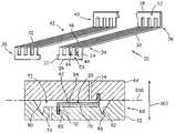
- FIG. 5shows three pre-molded cores 90 A, 90 B, and 90 C secured to a ceramic core 110 within a pattern die 112 in which the second wax application stage occurs.
- the second stagemay be a main stage in which the additional wax molded over the ceramic core and pre-molded cores constitutes a majority of the total wax of the ultimate pattern.
- the additional waxmay at least be of greater amount (e.g., volume) than the wax of any of the individual pre-molds.
- the additional waxmay be a lesser amount.
- the exemplary ceramic core 110is shown configured to form an airfoil element (e.g., a blade or vane of a gas turbine engine turbine section) and has leading, intermediate, and trailing sections 114 A, 114 B, and 114 C for forming corresponding main passageways and connected by a series of webs 116 for core structural integrity.
- the first pre-molded core 90 Ais mounted to a pressure side surface of the intermediate core section 114 B; the second pre-molded core 90 B is mounted to a suction side surface thereof; and the third pre-molded core 90 C is mounted to a suction side surface of the trailing core section 114 C.
- the distal portions 50 of the pre-molded RMCs 90 A, 90 B, and 90 Care accommodated within slots 118 , 119 , and 120 in the associated surface of the associated ceramic core sections. These distal portions 50 may be secured in place via ceramic adhesive in the slots. Additionally, or alternatively, the surfaces 94 of the first and second pre-molded RMCs may be wax welded or otherwise adhered to the adjacent ceramic core surface. Various additional RMCs (not shown) may be secured to the ceramic core in a similar fashion or otherwise.
- the core assemblymay then be placed in one of the die halves (e.g., a first half 122 ), with the protruding portions of the wall 98 of the second and third pre-molded cores 90 B and 90 C and their second distal portions 52 accommodated within compartments 124 and 125 . Interaction of the surfaces 102 of such pre-molded cores with the surfaces 126 and 127 of the compartments may help guide insertion of the core assembly into the die half 122 and locate and register the core assembly once inserted. Insertion may be along an axis 506 .
- the core assemblymay be registered by direct contact between the ceramic core and the die half (e.g., at ends (not shown) of the ceramic core which ends ultimately protrude from the pattern and do not form internal features of the cast part).
- the ceramic coremay have additional positioning or retention features such as projections 128 unitarily or otherwise integrally formed with the feed portions of the ceramic core. Possible such projections are shown in U.S. Pat. No. 5,296,308 of Caccavale et al.
- the die upper half 130may then be mated with the lower half 122 , with the first pre-molded core 90 A being accommodated within a compartment 132 in similar fashion to the accommodation of the second and third pre-molded cores 90 B and 90 C.
- Mating of the die halves (and their ultimate separation)may also be along the axis 506 or may be along an axis at an angle thereto.
- FIG. 5it can be seen how the angling of the perimeter surfaces of the pre-molded RMCs may facilitate joining and parting of the die halves 122 and 130 without destroying the pre-molded RMCs. The angling is sufficient to prevent backlocking when the die halves are separated and when the pattern is extracted.
- the end portions 52can extend at an angle to the axis 506 . This is permitted because the walls 98 or other surrounding pre-molding structure preclude the need for the die halves to closely accommodate the portions 52 . If the die halves closely accommodated the portions 52 , the portions 52 would have to be oriented parallel to the axis 506 to permit assembly/disassembly of the die halves and/or installation or removal of the pattern.
- one or more of the pre-molded coresmay be assembled first to an associated mold half and then to the ceramic core as the ceramic core is put in place or as the die halves are joined.
- the compartment for a pre-molded RMCmay span two die halves.
- FIG. 6shows the molded core assembly after removal, with tip portions 142 of the walls 98 protruding from pressure and suction side surfaces 144 and 146 of the pattern airfoil contour. These protruding portions may be cut off or otherwise removed leaving a smooth pattern surface contour from which the RMC second distal portions 52 protrude.
- the walls 98By forming the walls 98 as structure surrounding the distal portion 52 but with protruding portions spaced apart therefrom and leaving a surrounding volume (e.g., as opposed to embedding the end 52 in a plateau) only a relatively small amount of material needs to be removed and can be removed easily without producing unacceptable irregularities in the surface contour of the resulting pattern.
- the wallalso helps keep the distal portion clean for good subsequent adhesion to the shell. As more material is required to be removed, it becomes more difficult to remove such material while preserving a desired contour.
- the patternmay be assembled to a shelling fixture (e.g., via wax welding between upper and lower end plates of the fixture) and a multilayer coating 150 ( FIG. 7 ) applied for forming a shell.
- a dewax processmay remove the wax from the pattern (e.g., both the pre-molding wax and the main molding wax) leaving the RMCs and ceramic core within the shell.
- This core and shell assemblymay be fired to harden the shell.
- Molten metalmay then be introduced to the shell to fill the spaces between the core assembly and the shell.
- the shellmay be destructively removed (e.g., broken away via an impact apparatus) and the core assembly destructively removed (e.g., via a chemical immersion apparatus) from the cast metal to form a part precursor.
- the precursormay be subject to machining, treatment (e.g., thermal, mechanical, or chemical), and coating (e.g., ceramic heat resistant coating) to form the ultimate component.
- the foregoing teachingsmay be implemented in the manufacturing of pre-existing patterns (core combinations and wax shapes) or in to produce yet novel patterns.
- an existing single-stage molding processmay be relatively complex (e.g., having a large number of separate die parts and separate pull directions to accommodate the various RMCs)
- the main stage of a revised processmay be simplified (e.g., having fewer die parts and fewer single pulls, with as few as two and one, respectively). This may simplify engineering and/or manufacturing.
Landscapes
- Engineering & Computer Science (AREA)
- Mechanical Engineering (AREA)
- Molds, Cores, And Manufacturing Methods Thereof (AREA)
- Sorption Type Refrigeration Machines (AREA)
- Control Of Steam Boilers And Waste-Gas Boilers (AREA)
Abstract
Description
Claims (26)
Priority Applications (7)
| Application Number | Priority Date | Filing Date | Title |
|---|---|---|---|
| US10/867,230US7216689B2 (en) | 2004-06-14 | 2004-06-14 | Investment casting |
| ZA200503068AZA200503068B (en) | 2004-06-14 | 2005-04-15 | Investment casting |
| AU2005201580AAU2005201580B2 (en) | 2004-06-14 | 2005-04-15 | Investment casting |
| KR1020050038644AKR100611274B1 (en) | 2004-06-14 | 2005-05-10 | Investment casting |
| EP05253615AEP1611978B1 (en) | 2004-06-14 | 2005-06-13 | Investment casting |
| AT05253615TATE413937T1 (en) | 2004-06-14 | 2005-06-13 | INVESTMENT CASTING |
| DE602005010941TDE602005010941D1 (en) | 2004-06-14 | 2005-06-13 | Investment casting |
Applications Claiming Priority (1)
| Application Number | Priority Date | Filing Date | Title |
|---|---|---|---|
| US10/867,230US7216689B2 (en) | 2004-06-14 | 2004-06-14 | Investment casting |
Publications (2)
| Publication Number | Publication Date |
|---|---|
| US20050274478A1 US20050274478A1 (en) | 2005-12-15 |
| US7216689B2true US7216689B2 (en) | 2007-05-15 |
Family
ID=34941651
Family Applications (1)
| Application Number | Title | Priority Date | Filing Date |
|---|---|---|---|
| US10/867,230Expired - LifetimeUS7216689B2 (en) | 2004-06-14 | 2004-06-14 | Investment casting |
Country Status (7)
| Country | Link |
|---|---|
| US (1) | US7216689B2 (en) |
| EP (1) | EP1611978B1 (en) |
| KR (1) | KR100611274B1 (en) |
| AT (1) | ATE413937T1 (en) |
| AU (1) | AU2005201580B2 (en) |
| DE (1) | DE602005010941D1 (en) |
| ZA (1) | ZA200503068B (en) |
Cited By (19)
| Publication number | Priority date | Publication date | Assignee | Title |
|---|---|---|---|---|
| US20080060781A1 (en)* | 2005-09-01 | 2008-03-13 | United Technologies Corporation | Investment Casting Pattern Manufacture |
| US20080110024A1 (en)* | 2006-11-14 | 2008-05-15 | Reilly P Brennan | Airfoil casting methods |
| US20080131285A1 (en)* | 2006-11-30 | 2008-06-05 | United Technologies Corporation | RMC-defined tip blowing slots for turbine blades |
| EP2000232A1 (en) | 2007-06-07 | 2008-12-10 | United Technologies Corporation | Cooled wall thickness control |
| US20090258102A1 (en)* | 2005-06-23 | 2009-10-15 | Edward Pietraszkiewicz | Method for forming turbine blade with angled internal ribs |
| US20090301680A1 (en)* | 2006-08-10 | 2009-12-10 | United Technologies Corporation | Blade outer air seal cores and manufacture methods |
| US20100003142A1 (en)* | 2008-07-03 | 2010-01-07 | Piggush Justin D | Airfoil with tapered radial cooling passage |
| US20100054953A1 (en)* | 2008-08-29 | 2010-03-04 | Piggush Justin D | Airfoil with leading edge cooling passage |
| US20100098526A1 (en)* | 2008-10-16 | 2010-04-22 | Piggush Justin D | Airfoil with cooling passage providing variable heat transfer rate |
| US20100116452A1 (en)* | 2006-10-18 | 2010-05-13 | United Technologies Corporation | Investment casting cores and methods |
| US20100129217A1 (en)* | 2008-11-21 | 2010-05-27 | United Technologies Corporation | Castings, Casting Cores, and Methods |
| US20100150733A1 (en)* | 2008-12-15 | 2010-06-17 | William Abdel-Messeh | Airfoil with wrapped leading edge cooling passage |
| US20110180227A1 (en)* | 2008-10-17 | 2011-07-28 | Brp Us Inc. | Method and apparatus for consumable-pattern casting |
| US8251123B2 (en) | 2010-12-30 | 2012-08-28 | United Technologies Corporation | Casting core assembly methods |
| US20150290707A1 (en)* | 2014-04-15 | 2015-10-15 | United Technologies Corporation | Working additively manufactured parts |
| US20160319674A1 (en)* | 2015-05-01 | 2016-11-03 | United Technologies Corporation | Core arrangement for turbine engine component |
| EP3106245A4 (en)* | 2014-02-13 | 2017-11-01 | Hitachi Metals, Ltd. | Method for producing ceramic sintered body and ceramic sintered body |
| US20180214935A1 (en)* | 2017-01-27 | 2018-08-02 | Rolls-Royce Plc | Ceramic Core for an Investment Casting Process |
| US20210285336A1 (en)* | 2020-03-11 | 2021-09-16 | United Technologies Corporation | Investment casting core bumper for gas turbine engine article |
Families Citing this family (27)
| Publication number | Priority date | Publication date | Assignee | Title |
|---|---|---|---|---|
| US20050087319A1 (en)* | 2003-10-16 | 2005-04-28 | Beals James T. | Refractory metal core wall thickness control |
| US7686065B2 (en)* | 2006-05-15 | 2010-03-30 | United Technologies Corporation | Investment casting core assembly |
| DE102007012321A1 (en)* | 2007-03-09 | 2008-09-11 | Rolls-Royce Deutschland Ltd & Co Kg | Process for investment casting of metallic components with thin through-channels |
| US7779892B2 (en)* | 2007-05-09 | 2010-08-24 | United Technologies Corporation | Investment casting cores and methods |
| US8133553B2 (en) | 2007-06-18 | 2012-03-13 | Zimmer, Inc. | Process for forming a ceramic layer |
| US8309521B2 (en)* | 2007-06-19 | 2012-11-13 | Zimmer, Inc. | Spacer with a coating thereon for use with an implant device |
| US7950441B2 (en)* | 2007-07-20 | 2011-05-31 | GM Global Technology Operations LLC | Method of casting damped part with insert |
| US8608049B2 (en) | 2007-10-10 | 2013-12-17 | Zimmer, Inc. | Method for bonding a tantalum structure to a cobalt-alloy substrate |
| GB0901663D0 (en)* | 2009-02-04 | 2009-03-11 | Rolls Royce Plc | Casting method |
| GB0904492D0 (en)* | 2009-03-17 | 2009-04-29 | Rolls Royce Plc | Single crystal casting apparatus |
| CN102292465B (en) | 2009-05-20 | 2014-04-09 | 豪梅特公司 | Pt-Al-Hf/Zr Coating and Method |
| US20110094698A1 (en)* | 2009-10-28 | 2011-04-28 | Howmet Corporation | Fugitive core tooling and method |
| US9272324B2 (en) | 2009-12-08 | 2016-03-01 | Siemens Energy, Inc. | Investment casting process for hollow components |
| US20130333855A1 (en)* | 2010-12-07 | 2013-12-19 | Gary B. Merrill | Investment casting utilizing flexible wax pattern tool for supporting a ceramic core along its length during wax injection |
| US8302668B1 (en)* | 2011-06-08 | 2012-11-06 | United Technologies Corporation | Hybrid core assembly for a casting process |
| US9422817B2 (en)* | 2012-05-31 | 2016-08-23 | United Technologies Corporation | Turbine blade root with microcircuit cooling passages |
| US9486853B2 (en) | 2012-09-14 | 2016-11-08 | United Technologies Corporation | Casting of thin wall hollow airfoil sections |
| US20140102656A1 (en)* | 2012-10-12 | 2014-04-17 | United Technologies Corporation | Casting Cores and Manufacture Methods |
| US20160001354A1 (en)* | 2013-03-01 | 2016-01-07 | United Technologies Corporation | Gas turbine engine component manufacturing method and core for making same |
| WO2015017111A1 (en)* | 2013-07-31 | 2015-02-05 | United Technologies Corporation | Castings and manufacture methods |
| WO2015060989A1 (en)* | 2013-10-24 | 2015-04-30 | United Technologies Corporation | Lost core molding cores for forming cooling passages |
| WO2017164874A1 (en)* | 2016-03-24 | 2017-09-28 | Siemens Aktiengesellschaft | Method of manufacturing a hybridized core with protruding cast in cooling features for investment casting |
| CN109351912B (en)* | 2018-11-20 | 2020-11-27 | 安徽应流航源动力科技有限公司 | A kind of positioning mold and positioning method for adjusting engine blade ceramic core |
| US11203058B2 (en) | 2019-11-22 | 2021-12-21 | Raytheon Technologies Corporation | Turbine blade casting with strongback core |
| EP4069447B1 (en)* | 2020-01-13 | 2024-03-06 | Siemens Energy Global GmbH & Co. KG | Rapid manufacturing process for high definition ceramic core used for investment casting applications |
| CN113229972B (en)* | 2021-04-15 | 2022-07-22 | 厦门市仿真美义齿科技有限公司 | False tooth colorimetric mold forming die |
| EP4516423A1 (en)* | 2023-08-24 | 2025-03-05 | RTX Corporation | Casting core post and socket joint |
Citations (14)
| Publication number | Priority date | Publication date | Assignee | Title |
|---|---|---|---|---|
| US4160313A (en)* | 1975-09-25 | 1979-07-10 | Rolls-Royce Limited | Method of making a wax pattern for a shell mould |
| US4283835A (en) | 1980-04-02 | 1981-08-18 | United Technologies Corporation | Cambered core positioning for injection molding |
| US4487246A (en)* | 1982-04-12 | 1984-12-11 | Howmet Turbine Components Corporation | System for locating cores in casting molds |
| US5291654A (en)* | 1993-03-29 | 1994-03-08 | United Technologies Corporation | Method for producing hollow investment castings |
| US5296308A (en) | 1992-08-10 | 1994-03-22 | Howmet Corporation | Investment casting using core with integral wall thickness control means |
| US5405242A (en) | 1990-07-09 | 1995-04-11 | United Technologies Corporation | Cooled vane |
| US5640767A (en) | 1995-01-03 | 1997-06-24 | Gen Electric | Method for making a double-wall airfoil |
| US5853044A (en) | 1996-04-24 | 1998-12-29 | Pcc Airfoils, Inc. | Method of casting an article |
| US6505678B2 (en)* | 2001-04-17 | 2003-01-14 | Howmet Research Corporation | Ceramic core with locators and method |
| US6530416B1 (en) | 1998-05-14 | 2003-03-11 | Siemens Aktiengesellschaft | Method and device for producing a metallic hollow body |
| US6637500B2 (en)* | 2001-10-24 | 2003-10-28 | United Technologies Corporation | Cores for use in precision investment casting |
| US6668906B2 (en) | 2002-04-29 | 2003-12-30 | United Technologies Corporation | Shaped core for cast cooling passages and enhanced part definition |
| US6705831B2 (en) | 2002-06-19 | 2004-03-16 | United Technologies Corporation | Linked, manufacturable, non-plugging microcircuits |
| US20050087319A1 (en)* | 2003-10-16 | 2005-04-28 | Beals James T. | Refractory metal core wall thickness control |
- 2004
- 2004-06-14USUS10/867,230patent/US7216689B2/ennot_activeExpired - Lifetime
- 2005
- 2005-04-15AUAU2005201580Apatent/AU2005201580B2/ennot_activeExpired - Fee Related
- 2005-04-15ZAZA200503068Apatent/ZA200503068B/enunknown
- 2005-05-10KRKR1020050038644Apatent/KR100611274B1/ennot_activeExpired - Fee Related
- 2005-06-13EPEP05253615Apatent/EP1611978B1/ennot_activeExpired - Lifetime
- 2005-06-13DEDE602005010941Tpatent/DE602005010941D1/ennot_activeExpired - Lifetime
- 2005-06-13ATAT05253615Tpatent/ATE413937T1/ennot_activeIP Right Cessation
Patent Citations (15)
| Publication number | Priority date | Publication date | Assignee | Title |
|---|---|---|---|---|
| US4160313A (en)* | 1975-09-25 | 1979-07-10 | Rolls-Royce Limited | Method of making a wax pattern for a shell mould |
| US4283835A (en) | 1980-04-02 | 1981-08-18 | United Technologies Corporation | Cambered core positioning for injection molding |
| US4487246A (en)* | 1982-04-12 | 1984-12-11 | Howmet Turbine Components Corporation | System for locating cores in casting molds |
| US5405242A (en) | 1990-07-09 | 1995-04-11 | United Technologies Corporation | Cooled vane |
| US5296308A (en) | 1992-08-10 | 1994-03-22 | Howmet Corporation | Investment casting using core with integral wall thickness control means |
| US5291654A (en)* | 1993-03-29 | 1994-03-08 | United Technologies Corporation | Method for producing hollow investment castings |
| US5640767A (en) | 1995-01-03 | 1997-06-24 | Gen Electric | Method for making a double-wall airfoil |
| US5853044A (en) | 1996-04-24 | 1998-12-29 | Pcc Airfoils, Inc. | Method of casting an article |
| US6530416B1 (en) | 1998-05-14 | 2003-03-11 | Siemens Aktiengesellschaft | Method and device for producing a metallic hollow body |
| US6505678B2 (en)* | 2001-04-17 | 2003-01-14 | Howmet Research Corporation | Ceramic core with locators and method |
| US6637500B2 (en)* | 2001-10-24 | 2003-10-28 | United Technologies Corporation | Cores for use in precision investment casting |
| US20040020629A1 (en) | 2001-10-24 | 2004-02-05 | United Technologies Corporation | Cores for use in precision investment casting |
| US6668906B2 (en) | 2002-04-29 | 2003-12-30 | United Technologies Corporation | Shaped core for cast cooling passages and enhanced part definition |
| US6705831B2 (en) | 2002-06-19 | 2004-03-16 | United Technologies Corporation | Linked, manufacturable, non-plugging microcircuits |
| US20050087319A1 (en)* | 2003-10-16 | 2005-04-28 | Beals James T. | Refractory metal core wall thickness control |
Non-Patent Citations (1)
| Title |
|---|
| European Search Report for EP Patent Application No. 05253615.8. |
Cited By (36)
| Publication number | Priority date | Publication date | Assignee | Title |
|---|---|---|---|---|
| US20090258102A1 (en)* | 2005-06-23 | 2009-10-15 | Edward Pietraszkiewicz | Method for forming turbine blade with angled internal ribs |
| US7862325B2 (en)* | 2005-06-23 | 2011-01-04 | United Technologies Corporation | Apparatus for forming turbine blade with angled internal ribs |
| US20080060781A1 (en)* | 2005-09-01 | 2008-03-13 | United Technologies Corporation | Investment Casting Pattern Manufacture |
| US7438118B2 (en) | 2005-09-01 | 2008-10-21 | United Technologies Corporation | Investment casting pattern manufacture |
| US20090301680A1 (en)* | 2006-08-10 | 2009-12-10 | United Technologies Corporation | Blade outer air seal cores and manufacture methods |
| US7686068B2 (en) | 2006-08-10 | 2010-03-30 | United Technologies Corporation | Blade outer air seal cores and manufacture methods |
| US7753104B2 (en) | 2006-10-18 | 2010-07-13 | United Technologies Corporation | Investment casting cores and methods |
| US20100116452A1 (en)* | 2006-10-18 | 2010-05-13 | United Technologies Corporation | Investment casting cores and methods |
| US20080110024A1 (en)* | 2006-11-14 | 2008-05-15 | Reilly P Brennan | Airfoil casting methods |
| US20080131285A1 (en)* | 2006-11-30 | 2008-06-05 | United Technologies Corporation | RMC-defined tip blowing slots for turbine blades |
| EP2000232A1 (en) | 2007-06-07 | 2008-12-10 | United Technologies Corporation | Cooled wall thickness control |
| US20100014102A1 (en)* | 2007-06-07 | 2010-01-21 | United Technologies Corporation | Cooled Wall Thickness Control |
| US8066052B2 (en) | 2007-06-07 | 2011-11-29 | United Technologies Corporation | Cooled wall thickness control |
| US20100003142A1 (en)* | 2008-07-03 | 2010-01-07 | Piggush Justin D | Airfoil with tapered radial cooling passage |
| US8157527B2 (en) | 2008-07-03 | 2012-04-17 | United Technologies Corporation | Airfoil with tapered radial cooling passage |
| US20100054953A1 (en)* | 2008-08-29 | 2010-03-04 | Piggush Justin D | Airfoil with leading edge cooling passage |
| US8572844B2 (en) | 2008-08-29 | 2013-11-05 | United Technologies Corporation | Airfoil with leading edge cooling passage |
| US20100098526A1 (en)* | 2008-10-16 | 2010-04-22 | Piggush Justin D | Airfoil with cooling passage providing variable heat transfer rate |
| US8303252B2 (en) | 2008-10-16 | 2012-11-06 | United Technologies Corporation | Airfoil with cooling passage providing variable heat transfer rate |
| US20110180227A1 (en)* | 2008-10-17 | 2011-07-28 | Brp Us Inc. | Method and apparatus for consumable-pattern casting |
| US8215372B2 (en)* | 2008-10-17 | 2012-07-10 | Brp Us Inc. | Method and apparatus for consumable-pattern casting |
| US20100129217A1 (en)* | 2008-11-21 | 2010-05-27 | United Technologies Corporation | Castings, Casting Cores, and Methods |
| US8113780B2 (en) | 2008-11-21 | 2012-02-14 | United Technologies Corporation | Castings, casting cores, and methods |
| US8109725B2 (en) | 2008-12-15 | 2012-02-07 | United Technologies Corporation | Airfoil with wrapped leading edge cooling passage |
| US20100150733A1 (en)* | 2008-12-15 | 2010-06-17 | William Abdel-Messeh | Airfoil with wrapped leading edge cooling passage |
| US8333233B2 (en) | 2008-12-15 | 2012-12-18 | United Technologies Corporation | Airfoil with wrapped leading edge cooling passage |
| US8251123B2 (en) | 2010-12-30 | 2012-08-28 | United Technologies Corporation | Casting core assembly methods |
| EP3106245A4 (en)* | 2014-02-13 | 2017-11-01 | Hitachi Metals, Ltd. | Method for producing ceramic sintered body and ceramic sintered body |
| US20150290707A1 (en)* | 2014-04-15 | 2015-10-15 | United Technologies Corporation | Working additively manufactured parts |
| US9604280B2 (en) | 2014-04-15 | 2017-03-28 | United Technologies Corporation | Working additively manufactured parts |
| US9463506B2 (en)* | 2014-04-15 | 2016-10-11 | United Technologies Corporation | Working additively manufactured parts |
| US20160319674A1 (en)* | 2015-05-01 | 2016-11-03 | United Technologies Corporation | Core arrangement for turbine engine component |
| US10406596B2 (en)* | 2015-05-01 | 2019-09-10 | United Technologies Corporation | Core arrangement for turbine engine component |
| US20180214935A1 (en)* | 2017-01-27 | 2018-08-02 | Rolls-Royce Plc | Ceramic Core for an Investment Casting Process |
| US20210285336A1 (en)* | 2020-03-11 | 2021-09-16 | United Technologies Corporation | Investment casting core bumper for gas turbine engine article |
| US11242768B2 (en)* | 2020-03-11 | 2022-02-08 | Raytheon Technologies Corporation | Investment casting core bumper for gas turbine engine article |
Also Published As
| Publication number | Publication date |
|---|---|
| AU2005201580B2 (en) | 2007-03-01 |
| EP1611978A1 (en) | 2006-01-04 |
| KR20060045990A (en) | 2006-05-17 |
| ATE413937T1 (en) | 2008-11-15 |
| AU2005201580A1 (en) | 2006-01-05 |
| ZA200503068B (en) | 2007-04-25 |
| KR100611274B1 (en) | 2006-08-10 |
| US20050274478A1 (en) | 2005-12-15 |
| DE602005010941D1 (en) | 2008-12-24 |
| EP1611978B1 (en) | 2008-11-12 |
Similar Documents
| Publication | Publication Date | Title |
|---|---|---|
| US7216689B2 (en) | Investment casting | |
| JP6537221B2 (en) | Ceramic core for airfoil casting with composite inserts | |
| US7172012B1 (en) | Investment casting | |
| US7278463B2 (en) | Investment casting cores and methods | |
| US9835035B2 (en) | Cast-in cooling features especially for turbine airfoils | |
| JP4906210B2 (en) | Multilayer core and manufacturing method thereof | |
| JP6000629B2 (en) | Ceramic core with composite inserts used for airfoil casting | |
| US8100165B2 (en) | Investment casting cores and methods | |
| EP1772209B1 (en) | Investment casting pattern manufacture | |
| US7779892B2 (en) | Investment casting cores and methods | |
| US20130333855A1 (en) | Investment casting utilizing flexible wax pattern tool for supporting a ceramic core along its length during wax injection | |
| US20070284411A1 (en) | Investment casting core assembly | |
| US12365022B1 (en) | Core firing setter | |
| HK1196331B (en) | Cast-in cooling features especially for turbine airfoils |
Legal Events
| Date | Code | Title | Description |
|---|---|---|---|
| AS | Assignment | Owner name:UNITED TECHNOLOGIES CORPORATION, CONNECTICUT Free format text:ASSIGNMENT OF ASSIGNORS INTEREST;ASSIGNORS:VERNER, CARL R.;BEALS, JAMES T.;SNYDER, JACOB A.;AND OTHERS;REEL/FRAME:015475/0120;SIGNING DATES FROM 20040603 TO 20040609 | |
| STCF | Information on status: patent grant | Free format text:PATENTED CASE | |
| CC | Certificate of correction | ||
| CC | Certificate of correction | ||
| FPAY | Fee payment | Year of fee payment:4 | |
| FPAY | Fee payment | Year of fee payment:8 | |
| MAFP | Maintenance fee payment | Free format text:PAYMENT OF MAINTENANCE FEE, 12TH YEAR, LARGE ENTITY (ORIGINAL EVENT CODE: M1553); ENTITY STATUS OF PATENT OWNER: LARGE ENTITY Year of fee payment:12 | |
| AS | Assignment | Owner name:RAYTHEON TECHNOLOGIES CORPORATION, MASSACHUSETTS Free format text:CHANGE OF NAME;ASSIGNOR:UNITED TECHNOLOGIES CORPORATION;REEL/FRAME:054062/0001 Effective date:20200403 | |
| AS | Assignment | Owner name:RAYTHEON TECHNOLOGIES CORPORATION, CONNECTICUT Free format text:CORRECTIVE ASSIGNMENT TO CORRECT THE AND REMOVE PATENT APPLICATION NUMBER 11886281 AND ADD PATENT APPLICATION NUMBER 14846874. TO CORRECT THE RECEIVING PARTY ADDRESS PREVIOUSLY RECORDED AT REEL: 054062 FRAME: 0001. ASSIGNOR(S) HEREBY CONFIRMS THE CHANGE OF ADDRESS;ASSIGNOR:UNITED TECHNOLOGIES CORPORATION;REEL/FRAME:055659/0001 Effective date:20200403 | |
| AS | Assignment | Owner name:RTX CORPORATION, CONNECTICUT Free format text:CHANGE OF NAME;ASSIGNOR:RAYTHEON TECHNOLOGIES CORPORATION;REEL/FRAME:064714/0001 Effective date:20230714 |