US7216665B1 - Retractable reel - Google Patents
Retractable reelDownload PDFInfo
- Publication number
- US7216665B1 US7216665B1US10/872,279US87227904AUS7216665B1US 7216665 B1US7216665 B1US 7216665B1US 87227904 AUS87227904 AUS 87227904AUS 7216665 B1US7216665 B1US 7216665B1
- Authority
- US
- United States
- Prior art keywords
- spool
- retractable reel
- wound
- tube
- chamber
- Prior art date
- Legal status (The legal status is an assumption and is not a legal conclusion. Google has not performed a legal analysis and makes no representation as to the accuracy of the status listed.)
- Expired - Fee Related, expires
Links
Images


Classifications
- A—HUMAN NECESSITIES
- A61—MEDICAL OR VETERINARY SCIENCE; HYGIENE
- A61M—DEVICES FOR INTRODUCING MEDIA INTO, OR ONTO, THE BODY; DEVICES FOR TRANSDUCING BODY MEDIA OR FOR TAKING MEDIA FROM THE BODY; DEVICES FOR PRODUCING OR ENDING SLEEP OR STUPOR
- A61M39/00—Tubes, tube connectors, tube couplings, valves, access sites or the like, specially adapted for medical use
- A61M39/08—Tubes; Storage means specially adapted therefor
- B—PERFORMING OPERATIONS; TRANSPORTING
- B65—CONVEYING; PACKING; STORING; HANDLING THIN OR FILAMENTARY MATERIAL
- B65H—HANDLING THIN OR FILAMENTARY MATERIAL, e.g. SHEETS, WEBS, CABLES
- B65H75/00—Storing webs, tapes, or filamentary material, e.g. on reels
- B65H75/02—Cores, formers, supports, or holders for coiled, wound, or folded material, e.g. reels, spindles, bobbins, cop tubes, cans, mandrels or chucks
- B65H75/34—Cores, formers, supports, or holders for coiled, wound, or folded material, e.g. reels, spindles, bobbins, cop tubes, cans, mandrels or chucks specially adapted or mounted for storing and repeatedly paying-out and re-storing lengths of material provided for particular purposes, e.g. anchored hoses, power cables
- B65H75/38—Cores, formers, supports, or holders for coiled, wound, or folded material, e.g. reels, spindles, bobbins, cop tubes, cans, mandrels or chucks specially adapted or mounted for storing and repeatedly paying-out and re-storing lengths of material provided for particular purposes, e.g. anchored hoses, power cables involving the use of a core or former internal to, and supporting, a stored package of material
- B65H75/44—Constructional details
- B65H75/4418—Arrangements for stopping winding or unwinding; Arrangements for releasing the stop means
- B65H75/4428—Arrangements for stopping winding or unwinding; Arrangements for releasing the stop means acting on the reel or on a reel blocking mechanism
- B65H75/4431—Manual stop or release button
- B—PERFORMING OPERATIONS; TRANSPORTING
- B65—CONVEYING; PACKING; STORING; HANDLING THIN OR FILAMENTARY MATERIAL
- B65H—HANDLING THIN OR FILAMENTARY MATERIAL, e.g. SHEETS, WEBS, CABLES
- B65H75/00—Storing webs, tapes, or filamentary material, e.g. on reels
- B65H75/02—Cores, formers, supports, or holders for coiled, wound, or folded material, e.g. reels, spindles, bobbins, cop tubes, cans, mandrels or chucks
- B65H75/34—Cores, formers, supports, or holders for coiled, wound, or folded material, e.g. reels, spindles, bobbins, cop tubes, cans, mandrels or chucks specially adapted or mounted for storing and repeatedly paying-out and re-storing lengths of material provided for particular purposes, e.g. anchored hoses, power cables
- B65H75/38—Cores, formers, supports, or holders for coiled, wound, or folded material, e.g. reels, spindles, bobbins, cop tubes, cans, mandrels or chucks specially adapted or mounted for storing and repeatedly paying-out and re-storing lengths of material provided for particular purposes, e.g. anchored hoses, power cables involving the use of a core or former internal to, and supporting, a stored package of material
- B65H75/44—Constructional details
- B65H75/4449—Arrangements or adaptations to avoid movable contacts or rotary couplings, e.g. by the use of an expansion chamber for a lenght of the cord or hose
- B—PERFORMING OPERATIONS; TRANSPORTING
- B65—CONVEYING; PACKING; STORING; HANDLING THIN OR FILAMENTARY MATERIAL
- B65H—HANDLING THIN OR FILAMENTARY MATERIAL, e.g. SHEETS, WEBS, CABLES
- B65H2701/00—Handled material; Storage means
- B65H2701/30—Handled filamentary material
- B65H2701/33—Hollow or hose-like material
- Y—GENERAL TAGGING OF NEW TECHNOLOGICAL DEVELOPMENTS; GENERAL TAGGING OF CROSS-SECTIONAL TECHNOLOGIES SPANNING OVER SEVERAL SECTIONS OF THE IPC; TECHNICAL SUBJECTS COVERED BY FORMER USPC CROSS-REFERENCE ART COLLECTIONS [XRACs] AND DIGESTS
- Y10—TECHNICAL SUBJECTS COVERED BY FORMER USPC
- Y10T—TECHNICAL SUBJECTS COVERED BY FORMER US CLASSIFICATION
- Y10T137/00—Fluid handling
- Y10T137/6851—With casing, support, protector or static constructional installations
- Y10T137/6918—With hose storage or retrieval means
- Y10T137/6925—With flow regulation responsive to hose movement
- Y10T137/6929—Reel type
- Y—GENERAL TAGGING OF NEW TECHNOLOGICAL DEVELOPMENTS; GENERAL TAGGING OF CROSS-SECTIONAL TECHNOLOGIES SPANNING OVER SEVERAL SECTIONS OF THE IPC; TECHNICAL SUBJECTS COVERED BY FORMER USPC CROSS-REFERENCE ART COLLECTIONS [XRACs] AND DIGESTS
- Y10—TECHNICAL SUBJECTS COVERED BY FORMER USPC
- Y10T—TECHNICAL SUBJECTS COVERED BY FORMER US CLASSIFICATION
- Y10T137/00—Fluid handling
- Y10T137/6851—With casing, support, protector or static constructional installations
- Y10T137/6918—With hose storage or retrieval means
- Y10T137/6954—Reel with support therefor
Definitions
- the present inventionrelates generally to a tube included in an infusion set used with an insulin pump and, more particularly, to a retractable reel for retracting, storing, and releasing the tube when needed.
- Diabetesis a widely known disease that affects a human body's ability to produce insulin.
- Insulinis produced and used by the human body to regulate blood glucose levels. If the human body does not produce adequate amounts of insulin, insulin must be introduced into the human body artificially. Insulin is commonly introduced into the human body by injection. Typically, the amount of insulin needed by the human body to regulate blood glucose levels determines how often an injection is required. If large amounts of insulin are needed by the human body, a diabetic patient will require a number of daily injections. To alleviate the requirement of multiple daily injections or to escape the need for injections altogether, an insulin pump can be utilized by the diabetic patient as a substitute for injections. Insulin pumps contain a supply of insulin that is pumped directly into the human body at a continuous level on an intermittent basis.
- the insulin pumpnormally supplies insulin to the human body through a tube.
- One end of the tubeis attached to the insulin pump and the opposite end is attached to a needle or cannula that is inserted under the diabetic patient's skin, typically on the abdomen.
- An adhesive patchis placed over the area where the needle or cannula enters the skin and is used to ensure the needle or cannula remains in place under the skin.
- the tube, needle or cannula, and adhesive patchcreate a tubular assembly.
- the tubular assemblyis commonly known as an infusion set.
- Insulin pumpsare small enough to be worn by diabetic patients under clothing and are typically clipped to a belt or waist band. At times, however, the insulin pump will have to be removed from the waist area. For example, because the amount of insulin needed by the human body is monitored by the diabetic patient, the diabetic patient needs to be able to read the output monitor of the insulin pump to ensure that the proper dose of insulin is being delivered. At the same time, the diabetic patient does not want to remove the needle or cannula from under the skin or disconnect the tube from the pump or needle or cannula in order to move the pump into a position to read the monitor.
- Conventional infusion setsinclude tubing of sufficient length to allow the diabetic patient to move the insulin pump to a comfortable reading location without disconnecting the tube from the insulin pump or needle or cannula. While there are occasions when the insulin pump must be removed from the patient's abdomen and the additional length of tube is required, much of the time the insulin pump is positioned at the diabetic patient's waist. The additional length of tube poses a potential hazard, as it can become snagged on objects around the home, office, etc., which may cause the needle or cannula to be removed from the patient. In an attempt to alleviate the problem of catching the tube on an object, a diabetic patient may coil the excess tube and keep the coiled tube close to the insulin pump. This coiling of the tube may lead to kinks in the tube, causing an interruption in the flow of insulin.
- the secure storage of the excess tubewill help to alleviate the possibility of catching the excess tube on an object as well as prevent a tube from becoming kinked or otherwise damaged in a way that would compromise the flow of insulin into the patient'body.
- a retractable reelincludes a housing having a front cover and a rear cover, the rear cover including a first opening and the front cover including a second opening, a trough extending radially inward from the second opening to a center of the front cover, the trough including at least one tab and at least one dimple, and a resiliently deflectable latch arm.
- a spoolincludes a wall that extends axially outward from a front surface of the spool, the spool is rotatably supported within the housing and is positioned such that the front surface, the wall, and the front cover cooperatively define a chamber therebetween.
- the spoolfurther includes at least one ratchet member selectively engaged by the resiliently deflectable latch arm to prevent rotation of the spool in a winding direction.
- the retractable reelincludes a spring having a first end engaging the rear cover and a second end engaging the spool for rotatively biasing the spool in the winding direction.
- the retractable reelalso includes a flexible member having a first portion that passes through the first opening and is spirally wound upon the spool and a second portion that passes through the second opening, the second portion having a first section secured to the housing in the trough by the tab and the dimple and a second section spirally wound within the chamber.
- the first portion of the flexible membermay be selectively unwound from the spool as the second portion of the flexible member is unwound and wound about itself within the chamber or wound upon the spool as the second portion of the flexible member is unwound and wound about itself within the chamber.
- a medical systemthat includes an insulin pump and a retractable reel according to the present invention is also disclosed.
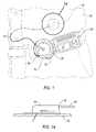
- FIG. 1is a perspective view of a medical system, including a retractable reel and an insulin pump, attached to a diabetic patient according to an embodiment of the present invention
- FIG. 1Ais a side elevational view of a needle or cannula for use in the medical system of FIG. 1 ;
- FIG. 2is an exploded view of the retractable reel according to an embodiment of the present invention.
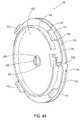
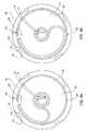
- FIGS. 3A and 3Bare perspective views of a front cover according to an embodiment of the present invention.
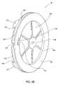
- FIGS. 4A and 4Bare perspective views of a spool according to an embodiment of the present invention.
- FIGS. 5A and 5Bare perspective views of a rear cover according to an embodiment of the present invention.
- FIG. 6is a plan view of a spring, the rear cover, and a portion of the spool according to an embodiment of the present invention
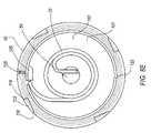
- FIG. 7Ais a cross-sectional view of the retractable reel according to an embodiment of the present invention.
- FIG. 7Bis a cross-sectional view of the front cover according to an embodiment of the present invention.
- FIGS. 7C and 7Dare cross-sectional views of a trough according to an embodiment of the present invention.
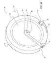
- FIGS. 8A , 8 B, 8 C, 8 D, and 8 Eare detailed plan views of the spool and a flexible member according to an embodiment of the present invention shown in different states of extraction and retraction;
- FIGS. 9A and 9Bare cross-sectional views of the retractable reel according to another embodiment of the present invention.
- FIGS. 10A and 10Bare perspective views of the spool and the flexible member according to another embodiment of the present invention shown in the extracted and retracted states respectively.
- FIGS. 11A , 11 B, and 11 Care detailed views of the front cover and the spool according to an embodiment of the present invention.
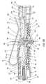
- FIG. 12is an elevation view of a medical system, including the retractable reel and the insulin pump, according to another embodiment of the present invention.
- FIGS. 1 and 1Aa medical system including an insulin pump 20 for diabetic therapy in cooperation with a tube 22 and a retractable reel 24 is shown according to an embodiment of the invention.
- Insulin pump 20is attached to a diabetic patient 26 by tube 22 , which is used to transfer a predetermined amount of insulin from insulin pump 20 to diabetic patient 26 .
- Tube 22is connected to insulin pump 20 at a first tubular end 28 and to diabetic patient 26 , through a needle or cannula member 30 , at a second tubular end 32 . Needle or cannula 30 is inserted into patient's 26 skin and held in place with the aid of an adhesive patch or strips (not shown).
- insulin pump 20is positioned at the waist of diabetic patient 26 ; however, diabetic patient 26 may be required to monitor insulin pump 20 periodically to adjust for changes in blood glucose levels. Therefore, tube 22 must be long enough to permit diabetic patient 26 to position insulin pump 20 in a readable location. The excess length of tube 22 required to position insulin pump 20 for comfortable reading, poses a hazard to diabetic patient 26 when insulin pump 20 is positioned for normal operation at the waist because excess tube 22 may become caught on objects or kinked.
- retractable reel 24is configured to take-up and encase at least a portion of tube 22 when not in use by diabetic patient 26 to locate insulin pump 20 in a readable location. By encasing a portion of tube 22 in retractable reel 24 , tube 22 will be less likely to kink or become snagged on objects, thus ensuring an uninterrupted flow of insulin to diabetic patient 26 .
- Retractable reel 24may be utilized with any number of insulin pumps such as, but not limited to, the insulin pumps manufactured by Medtronic, Animas, Dana, Deltec, Disetronic, or Nipro.
- retractable reel 24includes tube 22 and a housing 34 having a front cover 36 and a rear cover 38 .
- a spool 40is positioned between front and rear covers 36 , 38 of housing 34 and is biased by a spring 42 in one of two rotational directions.
- Reel device 24may also include a clip 46 for attaching retractable reel 24 to another object, such as a belt worn by diabetic patient 26 .
- front cover 36includes a radially extending wall 51 , having an interior surface 48 , and an exterior surface 50 , and an axially extending wall 52 that extends generally perpendicular from wall 51 .
- a first hub 54extends axially outward from wall 51 and includes a first hole 56 therethrough.
- a trough 58extends radially inward from side wall 52 through interior surface 48 and first hub 54 . Trough 58 is angled slightly from side wall 52 to avoid passing through first hole 56 .
- Trough 58may be sized to snugly hold tube 22 and, when so configured, may include dimples 60 to prevent tube 22 from moving axially within trough 58 and a lock 62 to prevent tube 22 from escaping trough 58 and interfering with tube 22 during operation of retractable reel 24 (See FIGS. 7B , 7 C, and 7 D). Top portion of dimples 60 are conically shaped to allow for a lower push in force when tube 22 is pressed into trough 58 . Trough 58 further includes a ramp 64 to direct tube 22 onto interior surface 48 . The walls of trough 58 that exits first hub 54 at ramp 64 are curved so as not to damage tube 22 as tube 22 is directed onto interior surface 48 .
- radially extending wall 51includes a chamfer 66 that extends axially outward from interior surface 48 .
- Wall 51is angled radially inward from an edge 68 of chamfer 66 toward first hub 54 .
- Chamfer 66allows for the inward angling of interior surface 48 toward first hub 54 to help ensure uniform winding and safe storage of tube 22 as tube 22 is wound about first hub 54 .
- the uniform winding and safe storage of tube 22will aid in preventing tube 22 from becoming kinked or entangled.
- Exterior surface 50 of wall 51includes an arcuate surface 70 that extends radially inward from side wall 52 through exterior surface 50 and first hub 54 .
- Arcuate surface 70provides a localized area of increased material on exterior surface 50 to allow trough 58 to run below interior surface 48 so that tube 22 can be held snugly in position.
- First hole 56includes a countersink 72 that extends axially inward toward exterior surface 50 .
- Wall 51also includes a notch 74 that provides clearance for a resiliently deflectable cantilever latch arm 76 of side wall 52 .
- latch arm 76includes a tab 78 and a locking post 82 that extends axially from a radially inner portion of tab 78 .
- locking post 82is generally triangular in shape having a pointed end 84 that expands to a wider end 86 .
- Tab 78 and locking post 82are configured to pass into and out of notch 74 when latch arm 76 is deflected radially inward toward first hub 54 . As shown in FIG.
- latch arm 76 and front cover 36are configured, such that when latch arm 76 is deflected radially inward toward first hub 54 , latch arm 76 will contact front cover 36 preventing latch arm 76 from moving too far inward.
- the width of latch arm 76will be almost as wide as retractable reel 24 itself making retractable reel 24 easy to operate for small children or patients 26 with large fingers.
- latch arm 76may exhibit a relatively low spring rate to allow diabetic patients 26 with weak fingers to operate retractable reel 24 .
- the design of latch arm 76ensures that there will not be a continuous pulling force at the site where needle or cannula 30 enters diabetic patient 26 . Even a small pulling force could loosen the adhesive patch that protects the site and dislodge needle or cannula 30 .
- Side wall 52also includes a “C”-channel 88 to allow tube 22 to enter and exit housing 34 .
- An arcuate surface 90extends radially outward from side wall 52 and at least partially surrounds “C”-channel 88 .
- Arcuate surface 90provides a smooth surface for tube 22 to travel upon as tube 22 is extracted from or retracted into housing 34 .
- Tube 22enters housing 34 through an opening 92 in side wall 52 and is pressed into trough 58 to limit movement of tube 22 during operation of retractable reel 24 .
- side wall 52includes a first pair of stepped surfaces 94 that face radially outward. Opening 92 and stepped surfaces 94 are sized to accept a first tab 96 on rear cover 38 .
- Side wall 52further includes a shoulder 98 sized to receive a lip 100 included on rear cover 38 .
- FIGS. 2 , 4 A, 4 B, and 7 Aillustrate spool 40 according to an embodiment of the invention.
- Spool 40includes a radially extending wall 101 having a front surface 102 and a rear surface 104 .
- Spool 40includes a second hub 106 extending radially outward from front surface 102 of wall 101 and includes a second hole 108 passing through second hub 106 and rear surface 104 .
- Front surface 102includes a groove 110 that surrounds second hub 106 and provides clearance for first hub 58 when spool 40 rotates in housing 34 .
- Front surface 102also includes at least one ratchet member 112 that extends axially outward from front surface 102 , proximate an outer edge 114 of spool 40 .
- spool 40employs four ratchet members 112 , which are generally triangular in shape and equally spaced about front surface 102 .
- Ratchet members 112include a pointed end 116 and a wider end 118 .
- Ratchet members 112are positioned to deflect or engage locking post 82 depending on the rotating direction of spool 40 .
- front surface 102also includes a “J”-shaped notch 120 that extends radially inward from first outer edge 114 .
- a first wall 122extends axially outward from front surface 102 and is located radially inward of ratchet members 112 .
- first hub 54 and interior surface 48 of front cover 36cooperate with front surface 102 and first wall 122 of spool 40 to form a chamber 124 to allow for expansion and contraction of tube 22 about first hub 54 (see FIG. 7A ).
- the width of chamber 124is slightly greater than the diameter of tube 22 to allow tube 22 to move freely in chamber 124 , yet aids in ensuring tube 22 will not become entangled or kinked while in chamber 124 .
- First wall 122includes a curved arcuate portion 126 that extends axially outward from front surface 102 to intersect the top of first wall 122 and at least partially surround and cover notch 120 .
- Tube 22is positioned and non-movably seated in notch 120 as tube 22 is routed out of chamber 124 so that tube 22 may not enter and exit chamber while spool 40 is rotating.
- rear surface 104 of spool 40includes a second wall 128 that extends axially outward from rear surface 104 .
- Second wall 128cooperates with rear surface 104 of rear cover 38 to encase spring 42 .
- Second wall 128is not continuous, but includes a split end 130 for attaching spring 42 .
- Rear surface 104also includes a flange 132 that extends radially outward from second wall 128 . (Flange 132 also includes a notch 136 to provide clearance to attach spring 42 to end 130 .)
- Flange 132 and rear surface 104cooperatively form a spool trough 134 for storage of tube 22 prior to the extraction of tube 22 out of housing 34 through “C”-channel 88 .
- the width of spool trough 134is slightly greater than the diameter of tube 22 to allow tube 22 to move freely in spool trough 134 , yet aids in ensuring tube 22 will not become entangled or kinked when accumulated therein.
- Rear cover 38includes a radially extending wall 137 having an interior surface 138 , an exterior surface 140 and an outer edge 142 .
- Rear cover 38also includes a base 144 that extends axially outward from interior surface 138 .
- a spindle 146that extends axially outward from base 144 and a first shoulder 148 is positioned between base 144 and spindle 146 .
- First shoulder 148provides a seat for second hub 106 of spool 40 and allows spool 40 to rotate freely about base 144 and spindle 146 in housing 34 .
- Spindle 146includes a first tower 150 sized to pass through second hole 108 in spool 40 , and a second tower 152 sized to pass through both second hole 108 and first hole 56 of front cover 36 .
- the height of first tower 150is slightly greater than the width of second hub 106 , which ensures that first hub 54 will seat on a second shoulder 154 rather than second hub 106 to prevent interference with the rotation of spool 40 .
- Base 144also includes a slot 156 sized to receive a portion of spring 42 .
- lip 100extends axially outward from interior surface 138 near outer edge 142 . Lip 100 cooperates with outer edge 142 to engage shoulder 98 of side wall 52 during assembly of rear cover 38 to front cover 36 .
- First tab 96extends axially outward from lip 100 at outer edge 142 and includes a second pair of stepped surfaces 158 . First tab 96 is sized to slide into opening 92 of front cover 36 and second pair of stepped surfaces 158 are sized to engage first pair of stepped surfaces 94 . The engagement of first pair of stepped surfaces 94 with second pair of stepped surfaces 158 acts as a lock to prevent front cover 36 from rotating about rear cover 38 .
- first tab 96includes a nib 162 that fits tight against tube 22 and captures tube 22 in trough 58 at opening 92 when rear cover 38 is assembled to front cover 36 .
- Rear cover 38also includes a second tab 164 that extends radially outward from rear cover 36 . Second tab 164 intersects shoulder 98 at “C”-channel 88 to further prevent front cover 36 from rotating about rear cover 38 .
- Rear cover 38further includes a notch 166 at outer edge 142 . Notch 166 provides clearance for latch arm 76 of front cover 36 when latch arm 76 is deflected radially inward toward first hub 54 and base 144 .
- exterior surface 140includes a scallop 168 for providing clearance for a curved end 170 of clip 46 , and a second slot 172 for accepting a connecting end 174 of clip 46 .
- Second slot 172passes through rear cover 38 and interior surface 138 includes a connecting tab 176 for securing clip 46 to rear cover 38 of housing 34 (see FIGS. 5A and 5B ).
- FIGS. 2 and 6illustrate spring 42 .
- spring 42is a typical spiral spring with a straight portion 178 for attaching to rear cover 38 at slot 156 on base 144 , a hook 180 for attaching to spool 40 at end 130 of second wall 128 , and a number of coils 182 .
- Spring 42is located in a cavity 184 created by interior surface 138 of rear cover 38 and second wall 128 of rear surface 104 on spool 40 .
- FIGS. 2 and 5Billustrate clip 46 according to an embodiment of the invention.
- clip 46is employed to attach retractable reel 24 to diabetic patient's 26 belt, waist band, suspender, purse strap, or the like.
- Curved end 170 of clipengages the belt and a flat end 174 enters second slot 172 on rear cover 38 .
- Flat end 174includes a cutout 186 for engaging connecting tab 176 to secure clip 46 to housing 34 .
- Front cover 36 , rear cover 38 , spool 40 , spring 42 , and clip 46may be manufactured from a metallic or polymeric material, such as steel, aluminum, plastic, nylon, or acetal.
- Front cover 38may be manufactured from a material that will ensure latch arm 76 maintains its resiliency during the useful life of retractable reel 24 .
- Spool 40may be manufactured from a material that will decrease the friction between ratchet members 112 of spool 40 and locking post 82 of front cover 36 , while spool 40 is rotating about front cover 36 .
- front cover 36may be manufactured from nylon and spool 40 may be manufactured from acetal. The combination of these materials will result in a lower frictional force at the ratchet member 112 /locking post 82 interface, than would result if the components were manufactured from the same materials.
- retractable reel 24is assembled in the following manner. A portion of tube 22 near second tubular end 32 is pressed snugly into trough 58 of front cover 36 at opening 92 . An adequate length of second tubular end 32 remains outside of opening 92 for connection to the needle or cannula 30 prior to insertion into diabetic patient 26 . As tube 22 exits trough 58 , tube 22 is spirally wound in a counterclockwise direction about first hub 54 . Tube 22 is continually wound about first hub 54 and itself in a spiral until first tubular end 28 is reached.
- Spool 40is then added to front cover 36 in a manner that presents ratchet members 112 of spool 40 to interior surface 48 of front cover 36 , while a section of tube 22 is looped around curved arcuate portion 126 and seated in “J”-shaped notch 120 of spool 40 .
- a section of tube 22is non-movably seated in the lower portion of “J”-shaped notch 120 while the remainder is fed into spool trough 134 .
- Tube 22is then wound in a counterclockwise direction about spool trough 134 relative to front cover 36 .
- a length of first tubular end 28exits through “C”-channel 88 of front cover 36 for connection to insulin pump 20 .
- Second hole 108 of spool 40is aligned with first hole 56 of front cover 36 and wider end 118 of at least one ratchet member 112 abuts wider end 86 of locking post 82 .
- Hook 180 of spring 42is attached to end 130 of second wall 128 on spool 40 .
- Straight portion 178 of spring 42is attached to slot 156 of base 144 .
- Rear cover 38is rotated in a counterclockwise direction to pre-load spring 42 prior to securing rear cover 38 to front cover 36 .
- Spindle 146may then be ultrasonically welded or “hot-staked”, which causes the portion of the diameter of spindle 146 proud of front cover 36 to increase so that the new diameter of spindle 146 is greater than the diameter of first hole 56 , thereby securing the assembly of rear cover 38 to spool 40 and front cover 36 .
- a top 188 of spindle 146may include a compressible gap 190 and ears 192 that pass through a second hole 108 and first hole 56 during assembly of retractable reel 24 (See FIG. 5A ).
- gap 190expands and forces ears 192 onto countersink 72 of front cover 36 , thereby securing the assembly of rear cover 38 to spool 40 and front cover 36 .
- Other fastening meansmay be employed in conjunction with or instead of the configuration described above.
- gluemay be used to assemble rear cover 38 to front cover 36 or another snap together feature could be employed.
- first tubular end 28will be connected to insulin pump 20 and second tubular end 32 will be connected to the needle or cannula 30 .
- the connection of tube 22 in this mannerensures that the retractable length of tube 22 is connected to insulin pump 20 and diabetic patient 26 has freedom to position insulin pump 20 for comfortable reading by removing the proper length of tube 22 from housing 34 .
- tube 22may have opposite female and male connectors fitted to either end that correspond to the correct fitting on insulin pump 20 and the needle or cannula 30 . This will eliminate any confusion on which side of tube 22 is to be connected to insulin pump 20 and the needle or cannula 30 .
- Retractable reel 24is operated by pulling first tubular end 28 out of “C”-channel 88 .
- spool 40As tube 22 is pulled from housing 34 , spool 40 is rotating in a counterclockwise direction relative to front cover 36 . Spool 40 is releasing tube 22 as it is rotated counterclockwise as well as loading spring 42 to rotate spool 40 in a clockwise direction.
- Tube 22is non-movably seated in the lower portion of the “J”-shaped notch 120 to aid diabetic patient 26 in extracting tube 22 .
- the lower portion of the “J”-shaped notch 120provides a pull point on spool 40 .
- tube 22As tube 22 is extracted, tube 22 is also pulling spool 40 in a counterclockwise direction.
- Tube 22will be non-moveably seated in “J”-shaped notch 120 on spool 40 and tube 22 may not enter or leave chamber 124 .
- Chamber 124will house a length of tube 22 that allows spool 40 to rotate freely and ensure tube 22 remains free of kinks.
- Tube 22will uncoil from itself, while remaining in chamber 124 , as tube 22 is extracted from spool trough 134 and spool 40 is rotated in a counterclockwise direction (see FIGS. 8E–8A ).
- tube 22When tube 22 is retracted into spool trough 134 , tube 22 will uncoil within chamber 124 until complete length of tube 22 is uncoiled, then tube 22 will coil about itself in a reverse spiral. (see FIGS. 8A–8E ).
- the continual coiling-uncoiling-coiling of tube 22 about itself within chamber 124allows retractable reel 24 to operate without a rotatable coupling, yet ensures that tube 22 will not become kinked or otherwise impede the flow of insulin through tube 22 .
- tube 22 contained in chamber 124may operate in this manner.
- Tube 22will uncoil from itself, while remaining in chamber 124 , as tube 22 is extracted from spool trough 134 and spool 40 is rotated in a counterclockwise direction (see FIGS. 9B and 10A ).
- tube 22 in chamber 124will recoil onto itself (see FIGS. 9A and 10B ).
- ratchet members 112generally triangular in shape, are employed and are spaced at 90° intervals on front surface 102 of spool 40 .
- the use of four ratchet members 112allows for extraction and retraction of tube 22 in relatively small increments to limit the amount of tube 22 outside housing 34 and help reduce the risk of snagging tube 22 on objects.
- pointed end 116 of ratchet member 112approaches pointed end 84 of locking post 82 .
- Ratchet members 112are positioned on spool 40 such that when pointed end 116 engages pointed end 84 , pointed end 116 forces pointed end 84 radially inward toward first hub 54 and second hub 106 .
- This camming actiondeflects locking post 82 out of the travel path of ratchet members 112 and allows ratchet members 112 to pass by locking post 82 , spool 40 to rotate freely, and tube 22 to be readily pulled from housing 34 as needed.
- angles of pointed ends 84 and 116are small or shallow so that a very small amount of force is required for pointed end 116 of ratchet members 112 to deflect pointed end 84 of locking post out of the path of ratchet members 112 .
- spring 42When the desired length of tube 22 has been removed from housing 34 , spring 42 will be loaded to rotate spool 40 in a clockwise direction and retract tube 22 into housing 34 . To prevent the unwanted retraction of tube 22 , the first, wider end 86 of locking post 82 will engage the second, wider end 118 of ratchet member 112 and prevent spool 40 from rotating in a clockwise direction. The desired length of tube 22 will be locked in place and diabetic patient 26 can perform the needed operations with insulin pump 20 .
- diabetic patient 26can move latch arm 76 radially inward toward first hub 56 . Deflecting latch arm 76 radially inward also moves locking post 82 radially inward, thus removing the engagement of wider end 86 of locking post 82 with wider end 118 of ratchet member 112 . Locking post 82 is now out of the travel path of ratchet member 112 .
- Spool 40is able to rotate freely in a clockwise direction and retract tube 22 in housing 34 . Spool 40 will rotate freely until diabetic patient 26 releases latch arm 76 allowing latch arm 76 to move radially outward to its normal non-deflected position.
- Locking post 82will be in the travel path of ratchet member 112 such that wider end 86 of locking post 82 will engage wider end 118 of ratchet member 112 .
- a stop(not shown) may be added to tube 22 which may be used to engage arcuate surface 90 of “C”-channel 88 to inhibit the entire tube 22 from entering housing 34 .
- retractable reel 24will be manufactured with latch arm 76 at the bottom of housing 34 when positioned on diabetic patient 26 to allow retractable reel 24 to be operated by either right handed or left handed diabetic patients 26 with a natural hand motion by their fingers.
- the force required to pull tube 22 from housing 34may be relatively low so that in the event tube 22 does become snagged on a doorknob, stair banister, chair arm or the like, tube 22 will be extracted from housing 34 rather than cause needle or cannula 30 to be removed from the diabetic patient 26 .
- the force on tube 22 and housing 34may be high enough to alert diabetic patient 26 to a problem before the full length of tube 22 is extracted from housing 34 .
- retractable reel 24may be manufactured as thin as possible so that it can easily be hidden under clothing.
- Retractable reel 24is designed to be as flush to a diabetic patient's body 26 as possible with tube 22 both entering and exiting housing 34 perpendicular to spindle 146 .
- Retractable reel 24should be user friendly and robust because of the many types of users of retractable reel 24 including small children, active individuals, and older patients.
- Retractable reel 24should also be low cost as well because retractable reel 24 may be disposable or recyclable after three to seven days of use.
- FIG. 12illustrates another embodiment of the invention.
- retractable reel 24 ′can be attached directly to insulin pump 20 ′, thus eliminating the need for a separate clip 46 .
- the case of insulin pump 20 ′can be molded to accept a molded clip (not shown) on rear cover 38 ′ of retractable reel 24 ′.
- This embodimentallows for simultaneous operation of retractable reel 24 ′ while returning insulin pump 20 ′ to the normal operating location, usually the waist area of diabetic patient 26 .
- Tube 22 ′can be retracted at the same time as insulin pump 20 ′ and retractable reel 24 ′ are returned to the waist. This will aid in ensuring tube 22 ′ is retracted quickly and lessens the chance that tube 22 ′ could become snagged on an object.
- retractable reel 24has been fully shown and described with the use of tube 22 . It is important to note, however, that retractable reel 24 may be used with any type of elongated flexible member including, but not limited to, telephone cords, electrical cords, cable, or the like.
Landscapes
- Health & Medical Sciences (AREA)
- Heart & Thoracic Surgery (AREA)
- Pulmonology (AREA)
- Engineering & Computer Science (AREA)
- Anesthesiology (AREA)
- Biomedical Technology (AREA)
- Hematology (AREA)
- Life Sciences & Earth Sciences (AREA)
- Animal Behavior & Ethology (AREA)
- General Health & Medical Sciences (AREA)
- Public Health (AREA)
- Veterinary Medicine (AREA)
- Infusion, Injection, And Reservoir Apparatuses (AREA)
Abstract
Description
The present invention relates generally to a tube included in an infusion set used with an insulin pump and, more particularly, to a retractable reel for retracting, storing, and releasing the tube when needed.
Diabetes is a widely known disease that affects a human body's ability to produce insulin. Insulin is produced and used by the human body to regulate blood glucose levels. If the human body does not produce adequate amounts of insulin, insulin must be introduced into the human body artificially. Insulin is commonly introduced into the human body by injection. Typically, the amount of insulin needed by the human body to regulate blood glucose levels determines how often an injection is required. If large amounts of insulin are needed by the human body, a diabetic patient will require a number of daily injections. To alleviate the requirement of multiple daily injections or to escape the need for injections altogether, an insulin pump can be utilized by the diabetic patient as a substitute for injections. Insulin pumps contain a supply of insulin that is pumped directly into the human body at a continuous level on an intermittent basis. The insulin pump normally supplies insulin to the human body through a tube. One end of the tube is attached to the insulin pump and the opposite end is attached to a needle or cannula that is inserted under the diabetic patient's skin, typically on the abdomen. An adhesive patch is placed over the area where the needle or cannula enters the skin and is used to ensure the needle or cannula remains in place under the skin. The tube, needle or cannula, and adhesive patch create a tubular assembly. The tubular assembly is commonly known as an infusion set.
Insulin pumps are small enough to be worn by diabetic patients under clothing and are typically clipped to a belt or waist band. At times, however, the insulin pump will have to be removed from the waist area. For example, because the amount of insulin needed by the human body is monitored by the diabetic patient, the diabetic patient needs to be able to read the output monitor of the insulin pump to ensure that the proper dose of insulin is being delivered. At the same time, the diabetic patient does not want to remove the needle or cannula from under the skin or disconnect the tube from the pump or needle or cannula in order to move the pump into a position to read the monitor. Conventional infusion sets include tubing of sufficient length to allow the diabetic patient to move the insulin pump to a comfortable reading location without disconnecting the tube from the insulin pump or needle or cannula. While there are occasions when the insulin pump must be removed from the patient's abdomen and the additional length of tube is required, much of the time the insulin pump is positioned at the diabetic patient's waist. The additional length of tube poses a potential hazard, as it can become snagged on objects around the home, office, etc., which may cause the needle or cannula to be removed from the patient. In an attempt to alleviate the problem of catching the tube on an object, a diabetic patient may coil the excess tube and keep the coiled tube close to the insulin pump. This coiling of the tube may lead to kinks in the tube, causing an interruption in the flow of insulin.
Therefore, a need exists for a retractable reel that can be used with the tube of an infusion set and an insulin pump to ensure that excess tube can be stored securely. The secure storage of the excess tube will help to alleviate the possibility of catching the excess tube on an object as well as prevent a tube from becoming kinked or otherwise damaged in a way that would compromise the flow of insulin into the patient'body.
A retractable reel is provided that includes a housing having a front cover and a rear cover, the rear cover including a first opening and the front cover including a second opening, a trough extending radially inward from the second opening to a center of the front cover, the trough including at least one tab and at least one dimple, and a resiliently deflectable latch arm. A spool includes a wall that extends axially outward from a front surface of the spool, the spool is rotatably supported within the housing and is positioned such that the front surface, the wall, and the front cover cooperatively define a chamber therebetween. The spool further includes at least one ratchet member selectively engaged by the resiliently deflectable latch arm to prevent rotation of the spool in a winding direction. The retractable reel includes a spring having a first end engaging the rear cover and a second end engaging the spool for rotatively biasing the spool in the winding direction. The retractable reel also includes a flexible member having a first portion that passes through the first opening and is spirally wound upon the spool and a second portion that passes through the second opening, the second portion having a first section secured to the housing in the trough by the tab and the dimple and a second section spirally wound within the chamber. The first portion of the flexible member may be selectively unwound from the spool as the second portion of the flexible member is unwound and wound about itself within the chamber or wound upon the spool as the second portion of the flexible member is unwound and wound about itself within the chamber. A medical system that includes an insulin pump and a retractable reel according to the present invention is also disclosed.
The features and inventive aspects of the present invention will become more apparent upon reading the following detailed description, claims, and drawings, of which the following is a brief description:
Referring toFIGS. 1 and 1A , a medical system including aninsulin pump 20 for diabetic therapy in cooperation with atube 22 and aretractable reel 24 is shown according to an embodiment of the invention.Insulin pump 20 is attached to adiabetic patient 26 bytube 22, which is used to transfer a predetermined amount of insulin frominsulin pump 20 todiabetic patient 26.Tube 22 is connected to insulin pump20 at a firsttubular end 28 and todiabetic patient 26, through a needle orcannula member 30, at a secondtubular end 32. Needle orcannula 30 is inserted into patient's26 skin and held in place with the aid of an adhesive patch or strips (not shown).
Normally,insulin pump 20 is positioned at the waist ofdiabetic patient 26; however,diabetic patient 26 may be required to monitorinsulin pump 20 periodically to adjust for changes in blood glucose levels. Therefore,tube 22 must be long enough to permitdiabetic patient 26 to positioninsulin pump 20 in a readable location. The excess length oftube 22 required to positioninsulin pump 20 for comfortable reading, poses a hazard todiabetic patient 26 when insulin pump20 is positioned for normal operation at the waist becauseexcess tube 22 may become caught on objects or kinked.
In an embodiment,retractable reel 24 is configured to take-up and encase at least a portion oftube 22 when not in use bydiabetic patient 26 to locateinsulin pump 20 in a readable location. By encasing a portion oftube 22 inretractable reel 24,tube 22 will be less likely to kink or become snagged on objects, thus ensuring an uninterrupted flow of insulin todiabetic patient 26.Retractable reel 24 may be utilized with any number of insulin pumps such as, but not limited to, the insulin pumps manufactured by Medtronic, Animas, Dana, Deltec, Disetronic, or Nipro.
Referring toFIGS. 1–7D ,retractable reel 24 of the present invention will be described in greater detail. In an embodiment,retractable reel 24 includestube 22 and ahousing 34 having afront cover 36 and arear cover 38. Aspool 40 is positioned between front and rear covers36,38 ofhousing 34 and is biased by aspring 42 in one of two rotational directions.Reel device 24 may also include aclip 46 for attachingretractable reel 24 to another object, such as a belt worn bydiabetic patient 26.
As shown inFIGS. 2 ,3A,3B,7A,7B,7C, and7D,front cover 36 includes aradially extending wall 51, having aninterior surface 48, and anexterior surface 50, and anaxially extending wall 52 that extends generally perpendicular fromwall 51. Afirst hub 54 extends axially outward fromwall 51 and includes afirst hole 56 therethrough. Atrough 58 extends radially inward fromside wall 52 throughinterior surface 48 andfirst hub 54.Trough 58 is angled slightly fromside wall 52 to avoid passing throughfirst hole 56.Trough 58 may be sized to snugly holdtube 22 and, when so configured, may includedimples 60 to preventtube 22 from moving axially withintrough 58 and alock 62 to preventtube 22 from escapingtrough 58 and interfering withtube 22 during operation of retractable reel24 (SeeFIGS. 7B ,7C, and7D). Top portion ofdimples 60 are conically shaped to allow for a lower push in force whentube 22 is pressed intotrough 58.Trough 58 further includes aramp 64 to directtube 22 ontointerior surface 48. The walls oftrough 58 that exitsfirst hub 54 atramp 64 are curved so as not to damagetube 22 astube 22 is directed ontointerior surface 48.
As shown inFIGS. 7A and 7B , radially extendingwall 51 includes achamfer 66 that extends axially outward frominterior surface 48.Wall 51 is angled radially inward from anedge 68 ofchamfer 66 towardfirst hub 54.Chamfer 66 allows for the inward angling ofinterior surface 48 towardfirst hub 54 to help ensure uniform winding and safe storage oftube 22 astube 22 is wound aboutfirst hub 54. The uniform winding and safe storage oftube 22 will aid in preventingtube 22 from becoming kinked or entangled.
Referring toFIG. 4A ,front surface 102 also includes a “J”-shapednotch 120 that extends radially inward from firstouter edge 114. Afirst wall 122 extends axially outward fromfront surface 102 and is located radially inward ofratchet members 112. When assembled,first hub 54 andinterior surface 48 offront cover 36 cooperate withfront surface 102 andfirst wall 122 ofspool 40 to form achamber 124 to allow for expansion and contraction oftube 22 about first hub54 (seeFIG. 7A ). The width ofchamber 124 is slightly greater than the diameter oftube 22 to allowtube 22 to move freely inchamber 124, yet aids in ensuringtube 22 will not become entangled or kinked while inchamber 124.First wall 122 includes a curvedarcuate portion 126 that extends axially outward fromfront surface 102 to intersect the top offirst wall 122 and at least partially surround and covernotch 120.Tube 22 is positioned and non-movably seated innotch 120 astube 22 is routed out ofchamber 124 so thattube 22 may not enter and exit chamber whilespool 40 is rotating.
Referring toFIG. 4B ,rear surface 104 ofspool 40 includes asecond wall 128 that extends axially outward fromrear surface 104.Second wall 128 cooperates withrear surface 104 ofrear cover 38 to encasespring 42.Second wall 128 is not continuous, but includes asplit end 130 for attachingspring 42.Rear surface 104 also includes aflange 132 that extends radially outward fromsecond wall 128. (Flange 132 also includes anotch 136 to provide clearance to attachspring 42 to end130.)Flange 132 andrear surface 104 cooperatively form aspool trough 134 for storage oftube 22 prior to the extraction oftube 22 out ofhousing 34 through “C”-channel 88. The width ofspool trough 134 is slightly greater than the diameter oftube 22 to allowtube 22 to move freely inspool trough 134, yet aids in ensuringtube 22 will not become entangled or kinked when accumulated therein.
Referring toFIGS. 2 ,5A,5B, and7A, an embodiment ofrear cover 38 is shown. Rear cover38 includes aradially extending wall 137 having aninterior surface 138, anexterior surface 140 and anouter edge 142. Rear cover38 also includes a base144 that extends axially outward frominterior surface 138. Aspindle 146 that extends axially outward frombase 144 and afirst shoulder 148 is positioned betweenbase 144 andspindle 146.First shoulder 148 provides a seat forsecond hub 106 ofspool 40 and allowsspool 40 to rotate freely aboutbase 144 andspindle 146 inhousing 34.Spindle 146 includes afirst tower 150 sized to pass throughsecond hole 108 inspool 40, and asecond tower 152 sized to pass through bothsecond hole 108 andfirst hole 56 offront cover 36. In an embodiment, the height offirst tower 150 is slightly greater than the width ofsecond hub 106, which ensures thatfirst hub 54 will seat on asecond shoulder 154 rather thansecond hub 106 to prevent interference with the rotation ofspool 40.Base 144 also includes aslot 156 sized to receive a portion ofspring 42.
Referring toFIG. 5A ,lip 100 extends axially outward frominterior surface 138 nearouter edge 142.Lip 100 cooperates withouter edge 142 to engageshoulder 98 ofside wall 52 during assembly ofrear cover 38 tofront cover 36.First tab 96 extends axially outward fromlip 100 atouter edge 142 and includes a second pair of stepped surfaces158.First tab 96 is sized to slide intoopening 92 offront cover 36 and second pair of steppedsurfaces 158 are sized to engage first pair of stepped surfaces94. The engagement of first pair of steppedsurfaces 94 with second pair of steppedsurfaces 158 acts as a lock to preventfront cover 36 from rotating aboutrear cover 38. Anedge 160 offirst tab 96 includes anib 162 that fits tight againsttube 22 and capturestube 22 intrough 58 at opening92 whenrear cover 38 is assembled tofront cover 36. Rear cover38 also includes asecond tab 164 that extends radially outward fromrear cover 36.Second tab 164 intersectsshoulder 98 at “C”-channel 88 to further preventfront cover 36 from rotating aboutrear cover 38. Rear cover38 further includes anotch 166 atouter edge 142.Notch 166 provides clearance forlatch arm 76 offront cover 36 whenlatch arm 76 is deflected radially inward towardfirst hub 54 andbase 144.
In an embodiment of the invention,exterior surface 140 includes ascallop 168 for providing clearance for acurved end 170 ofclip 46, and asecond slot 172 for accepting a connectingend 174 ofclip 46.Second slot 172 passes throughrear cover 38 andinterior surface 138 includes a connectingtab 176 for securingclip 46 torear cover 38 of housing34 (seeFIGS. 5A and 5B ).
Referring again toFIGS. 2–7D , in this embodiment,retractable reel 24 is assembled in the following manner. A portion oftube 22 near secondtubular end 32 is pressed snugly intotrough 58 offront cover 36 atopening 92. An adequate length of secondtubular end 32 remains outside of opening92 for connection to the needle orcannula 30 prior to insertion intodiabetic patient 26. Astube 22exits trough 58,tube 22 is spirally wound in a counterclockwise direction aboutfirst hub 54.Tube 22 is continually wound aboutfirst hub 54 and itself in a spiral until firsttubular end 28 is reached.
As will be appreciated, firsttubular end 28 will be connected toinsulin pump 20 and secondtubular end 32 will be connected to the needle orcannula 30. The connection oftube 22 in this manner ensures that the retractable length oftube 22 is connected toinsulin pump 20 anddiabetic patient 26 has freedom to positioninsulin pump 20 for comfortable reading by removing the proper length oftube 22 fromhousing 34. To ensure that the connection is made in this manner,tube 22 may have opposite female and male connectors fitted to either end that correspond to the correct fitting oninsulin pump 20 and the needle orcannula 30. This will eliminate any confusion on which side oftube 22 is to be connected toinsulin pump 20 and the needle orcannula 30.
Referring now toFIGS. 8A–8E , as will be appreciated, the extractable length oftube 22 used in the operation ofretractable reel 24 will be retained inspool trough 134.Tube 22 will be non-moveably seated in “J”-shapednotch 120 onspool 40 andtube 22 may not enter or leavechamber 124.Chamber 124 will house a length oftube 22 that allowsspool 40 to rotate freely and ensuretube 22 remains free of kinks.Tube 22 will uncoil from itself, while remaining inchamber 124, astube 22 is extracted fromspool trough 134 andspool 40 is rotated in a counterclockwise direction (seeFIGS. 8E–8A ). Whentube 22 is retracted intospool trough 134,tube 22 will uncoil withinchamber 124 until complete length oftube 22 is uncoiled, thentube 22 will coil about itself in a reverse spiral. (seeFIGS. 8A–8E ). The continual coiling-uncoiling-coiling oftube 22 about itself withinchamber 124 allowsretractable reel 24 to operate without a rotatable coupling, yet ensures thattube 22 will not become kinked or otherwise impede the flow of insulin throughtube 22.
Now referring toFIGS. 9A ,9B,10A, and10B, in another embodiment of the invention,tube 22 contained inchamber 124 may operate in this manner.Tube 22 will uncoil from itself, while remaining inchamber 124, astube 22 is extracted fromspool trough 134 andspool 40 is rotated in a counterclockwise direction (seeFIGS. 9B and 10A ). Whentube 22 is retracted intospool trough 134,tube 22 inchamber 124 will recoil onto itself (seeFIGS. 9A and 10B ). The spiral expansion and contraction oftube 22 about itself withinchamber 124 allowsretractable reel 24 to operate without a rotatable coupling, yet ensures thattube 22 will not become kinked or otherwise impede the flow of insulin throughtube 22. This particular embodiment may prove advantageous when there is an excess amount oftube 22 available in a particular infusion set and storage of theexcess tube 22 is required.
Now referring toFIGS. 11A ,11B, and11C, in this particular embodiment, fourratchet members 112, generally triangular in shape, are employed and are spaced at 90° intervals onfront surface 102 ofspool 40. The use of fourratchet members 112 allows for extraction and retraction oftube 22 in relatively small increments to limit the amount oftube 22 outsidehousing 34 and help reduce the risk of snaggingtube 22 on objects. Asspool 40 is rotated in a counterclockwise direction, pointedend 116 ofratchet member 112 approaches pointedend 84 of lockingpost 82.Ratchet members 112 are positioned onspool 40 such that whenpointed end 116 engages pointedend 84, pointedend 116 forces pointedend 84 radially inward towardfirst hub 54 andsecond hub 106. This camming action deflects lockingpost 82 out of the travel path ofratchet members 112 and allows ratchetmembers 112 to pass by lockingpost 82,spool 40 to rotate freely, andtube 22 to be readily pulled fromhousing 34 as needed. In this particular embodiment, angles of pointed ends84 and116 are small or shallow so that a very small amount of force is required forpointed end 116 ofratchet members 112 to deflectpointed end 84 of locking post out of the path ofratchet members 112.
When the desired length oftube 22 has been removed fromhousing 34,spring 42 will be loaded to rotatespool 40 in a clockwise direction and retracttube 22 intohousing 34. To prevent the unwanted retraction oftube 22, the first,wider end 86 of lockingpost 82 will engage the second,wider end 118 ofratchet member 112 and preventspool 40 from rotating in a clockwise direction. The desired length oftube 22 will be locked in place anddiabetic patient 26 can perform the needed operations withinsulin pump 20.
When retraction oftube 22 into reel is desired,diabetic patient 26 can movelatch arm 76 radially inward towardfirst hub 56. Deflectinglatch arm 76 radially inward also moves lockingpost 82 radially inward, thus removing the engagement ofwider end 86 of lockingpost 82 withwider end 118 ofratchet member 112. Lockingpost 82 is now out of the travel path ofratchet member 112.Spool 40 is able to rotate freely in a clockwise direction and retracttube 22 inhousing 34.Spool 40 will rotate freely untildiabetic patient 26 releases latcharm 76 allowinglatch arm 76 to move radially outward to its normal non-deflected position. Lockingpost 82 will be in the travel path ofratchet member 112 such thatwider end 86 of lockingpost 82 will engagewider end 118 ofratchet member 112. Also, a stop (not shown) may be added totube 22 which may be used to engagearcuate surface 90 of “C”-channel 88 to inhibit theentire tube 22 from enteringhousing 34. Generally,retractable reel 24 will be manufactured withlatch arm 76 at the bottom ofhousing 34 when positioned ondiabetic patient 26 to allowretractable reel 24 to be operated by either right handed or left handeddiabetic patients 26 with a natural hand motion by their fingers.
As will be appreciated, the force required to pulltube 22 fromhousing 34 may be relatively low so that in theevent tube 22 does become snagged on a doorknob, stair banister, chair arm or the like,tube 22 will be extracted fromhousing 34 rather than cause needle orcannula 30 to be removed from thediabetic patient 26. However, the force ontube 22 andhousing 34 may be high enough to alertdiabetic patient 26 to a problem before the full length oftube 22 is extracted fromhousing 34.
As will be appreciated,retractable reel 24 may be manufactured as thin as possible so that it can easily be hidden under clothing.Retractable reel 24 is designed to be as flush to a diabetic patient'sbody 26 as possible withtube 22 both entering and exitinghousing 34 perpendicular tospindle 146.Retractable reel 24 should be user friendly and robust because of the many types of users ofretractable reel 24 including small children, active individuals, and older patients.Retractable reel 24 should also be low cost as well becauseretractable reel 24 may be disposable or recyclable after three to seven days of use.
Theretractable reel 24 has been fully shown and described with the use oftube 22. It is important to note, however, thatretractable reel 24 may be used with any type of elongated flexible member including, but not limited to, telephone cords, electrical cords, cable, or the like.
The present invention has been particularly shown and described with reference to the foregoing embodiments, which are merely illustrative of the best modes for carrying out the invention. It should be understood by those skilled in the art that various alternatives to the embodiments of the invention described herein may be employed in practicing the invention without departing from the spirit and scope of the invention as defined in the following claims. It is intended that the following claims define the scope of the invention and that the method and apparatus within the scope of these claims and their equivalents be covered thereby. This description of the invention should be understood to include all novel and non-obvious combinations of elements described herein, and claims may be presented in this or a later application to any novel and non-obvious combination of these elements. Moreover, the foregoing embodiments are illustrative, and no single feature or element is essential to all possible combinations that may be claimed in this or a later application.
Claims (23)
1. A retractable reel comprising:
a housing including a front cover and a rear cover, the rear cover including a first opening and the front cover including a second opening, a trough extending radially inward from the second opening to a center of the front cover, the trough including at least one tab and at least one dimple, and a resiliently deflectable latch arm;
a spool including a wall that extends axially outward from a front surface of the spool, the spool rotatably supported within the housing and positioned such that the front surface, the wall and the front cover cooperatively define a chamber therebetween, the spool further including at least one ratchet member selectively engaged by the resiliently deflectable latch arm to prevent rotation of the spool in a winding direction;
a spring including a first end engaging the rear cover and a second end engaging the spool for rotatively biasing the spool in the winding direction;
a flexible member including a first portion that passes through the first opening and is spirally wound upon the spool and a second portion that passes through the second opening, the second portion having a first section secured to the housing in the trough by the tab and dimple, and a second section spirally wound in the chamber; and
whereby the first portion of the flexible member may be selectively unwound from the spool as the second portion of the flexible member is unwound and wound about itself within the chamber or wound upon the spool as the second portion of the flexible member is unwound and wound about itself within the chamber.
2. The retractable reel ofclaim 1 , wherein the resiliently deflectable latch arm includes a locking post configured to allow passage of the ratchet member during rotation on the spool in an unwinding direction and to selectively engage and prevent rotation of the spool in the winding direction.
3. The retractable reel ofclaim 2 , wherein the resiliently deflectable latch arm is cantilevered over the ratchet member, the locking post and the ratchet member being configured to cause a radially inward deflection of the resiliently deflectable latch arm during engagement with the ratchet member to allow passage of the ratchet member and rotation of the spool.
4. The retractable reel ofclaim 1 further including a plurality of ratchet members.
5. The retractable reel ofclaim 1 , wherein the spool includes a trough sized to collect the first portion of the flexible member and a recess sized to receive the second portion of the flexible member.
6. The retractable reel ofclaim 5 , wherein the trough is slightly larger than the width of the flexible member.
7. The retractable reel ofclaim 1 , wherein first portion of the flexible member is unwound from the spool in a first direction and the second portion of the flexible member is unwound and wound within the chamber in the first direction.
8. The retractable reel ofclaim 7 , wherein the first portion of the flexible member is wound onto the spool in a second direction and the second portion of the flexible member is unwound and wound within the chamber in the second direction.
9. The retractable reel ofclaim 1 , wherein the flexible member includes a third, non-movable portion between the first and second portions.
10. The retractable reel ofclaim 1 , wherein the flexible member is one of tubing and wire.
11. The retractable reel ofclaim 1 , wherein the first and second portions of the flexible member include respective first and second tubular ends.
12. The retractable reel ofclaim 1 further including a clip secured to the housing.
13. A medical system, comprising:
an insulin pump; and
a retractable reel, the retractable reel including:
a housing having a a front cover, a rear cover, the rear cover including a first opening and the front cover including a second opening, a trough extending radially inward from the second opening to a center of the front cover, the trough including at least one tab and at least one dimple and a resiliently deflectable latch arm;
a spool having a wall that extends axially outward from a front surface of the spool, the spool rotatably supported within the housing and positioned such that the front surface, the wall, and the front cover cooperatively define a chamber therebetween, the spool further including at least one ratchet member selectively engaged by the resiliently deflectable latch arm to prevent rotation of the spool in a winding direction;
a spring including a first end engaging the rear cover and a second end engaging the spool for rotatively biasing the spool in the winding direction;
a length of flexible tubing that includes a first portion that passes through the first opening and is spirally wound upon the spool and a second portion that passes through the second opening, the second portion having a first section secured to the housing in the trough by the tab and dimple, and a second section spirally wound in the chamber;
a clip secured to the housing; and
whereby the first portion of the flexible tubing may be selectively unwound from the spool as the second portion of the flexible tubing is unwound and wound about itself within the chamber or wound upon the spool as the second portion of the flexible tubing is unwound and wound about itself within the chamber.
14. The medical system ofclaim 13 , wherein the resiliently deflectable latch arm includes a locking post configured to allow passage of the ratchet member during rotation on the spool in an unwinding direction and to selectively engage and prevent rotation of the spool in the winding direction.
15. The medical system ofclaim 14 , wherein the resiliently deflectable latch arm is cantilevered over the ratchet member, the locking post and the ratchet member being configured to cause a radially inward deflection of the resiliently deflectable latch arm during engagement with the ratchet member to allow passage of the ratchet member and rotation of the spool.
16. The medical system ofclaim 13 further including a plurality of ratchet members.
17. The medical system ofclaim 13 , wherein the spool includes a trough sized to collect the first portion of the flexible tubing and a recess sized to receive the second portion of the flexible tubing.
18. The medical system ofclaim 17 , wherein the trough is slightly larger than the width of the flexible tubing.
19. The medical system ofclaim 13 , wherein the first portion of the flexible tubing is unwound from the spool in a first direction and the second portion of the flexible tubing is unwound and wound within the chamber in the first direction.
20. The medical system ofclaim 19 , wherein the first portion of the flexible tubing is wound onto the spool in a second direction and the second portion of the flexible tubing is unwound and wound within the chamber in the second direction.
21. The medical system ofclaim 13 , wherein the flexible tubing includes a third, non-movable portion between the first and second portions.
22. The medical system ofclaim 13 , wherein the first and second portions of the flexible tubing include respective first and second tubular ends.
23. The medical system ofclaim 13 , wherein the retractable reel is secured to the insulin pump.
Priority Applications (1)
| Application Number | Priority Date | Filing Date | Title |
|---|---|---|---|
| US10/872,279US7216665B1 (en) | 2004-06-18 | 2004-06-18 | Retractable reel |
Applications Claiming Priority (1)
| Application Number | Priority Date | Filing Date | Title |
|---|---|---|---|
| US10/872,279US7216665B1 (en) | 2004-06-18 | 2004-06-18 | Retractable reel |
Publications (1)
| Publication Number | Publication Date |
|---|---|
| US7216665B1true US7216665B1 (en) | 2007-05-15 |
Family
ID=38015628
Family Applications (1)
| Application Number | Title | Priority Date | Filing Date |
|---|---|---|---|
| US10/872,279Expired - Fee RelatedUS7216665B1 (en) | 2004-06-18 | 2004-06-18 | Retractable reel |
Country Status (1)
| Country | Link |
|---|---|
| US (1) | US7216665B1 (en) |
Cited By (37)
| Publication number | Priority date | Publication date | Assignee | Title |
|---|---|---|---|---|
| US20060065772A1 (en)* | 2004-09-27 | 2006-03-30 | Deka Products Limited Partnership | Infusion set improvements |
| US20090277454A1 (en)* | 2008-05-06 | 2009-11-12 | Tom Davis | Gas Supply System |
| US8032053B2 (en) | 2008-05-29 | 2011-10-04 | Xerox Corporation | Drawer latch flexure mechanism |
| EP2386327A1 (en)* | 2010-05-12 | 2011-11-16 | F. Hoffmann-La Roche AG | Device for adjusting the length of infusion tubing |
| US20110303816A1 (en)* | 2010-06-11 | 2011-12-15 | Sennco Solutions, Inc. | Cable roller, system and/or method for extending and/or retracting a coiled cable |
| US20120074189A1 (en)* | 2006-01-12 | 2012-03-29 | Ameche H Kathleen | Portable Tethered Carrier and Method |
| US20120222194A1 (en)* | 2011-03-04 | 2012-09-06 | Martin Harry J | Compressed gas lens cleaning apparatus |
| US8280242B2 (en) | 2010-04-05 | 2012-10-02 | West Coast Chain Mfg. Co. | Camera-steadying device |
| US8387763B2 (en) | 2010-11-22 | 2013-03-05 | Telefonix, Inc. | Retractable cord reel |
| WO2013140736A1 (en)* | 2012-03-23 | 2013-09-26 | パナソニック株式会社 | Cord reel device |
| US8641618B2 (en) | 2007-06-27 | 2014-02-04 | Abbott Diabetes Care Inc. | Method and structure for securing a monitoring device element |
| US20140263801A1 (en)* | 2013-03-18 | 2014-09-18 | Response Engineering, Inc. | Rotatable cable guide for retractable cord reel |
| US8932216B2 (en) | 2006-08-07 | 2015-01-13 | Abbott Diabetes Care Inc. | Method and system for providing data management in integrated analyte monitoring and infusion system |
| US20150352275A1 (en)* | 2012-01-15 | 2015-12-10 | Yu Li | Portable contact-washing device for relieving and preventing symptoms associated with hemorrhoids |
| CN105173105A (en)* | 2015-08-04 | 2015-12-23 | 徐州创航科技有限公司 | Automatic cable coiling and uncoiling device used for mooring unmanned plane aircraft |
| US9392349B2 (en) | 2012-03-30 | 2016-07-12 | Hybrid Skillz Inc. | Cable retraction system |
| US9463951B1 (en) | 2013-07-05 | 2016-10-11 | Thomas Oliver Davis, JR. | Gas supply system |
| US20160354570A1 (en)* | 2015-06-08 | 2016-12-08 | Lorelyn Cajucom Arroyo | Oxygen Cord Retractor and Organizer |
| JP2017077252A (en)* | 2015-10-19 | 2017-04-27 | 晴美 山田 | Tube pull-out / kink prevention device |
| US9782076B2 (en) | 2006-02-28 | 2017-10-10 | Abbott Diabetes Care Inc. | Smart messages and alerts for an infusion delivery and management system |
| US20180318542A1 (en)* | 2017-05-02 | 2018-11-08 | Patricia Knowlson | Retractable tubing device |
| US10139185B2 (en)* | 2016-12-15 | 2018-11-27 | Revo Brand Group, Llc | Caliber-specific cleaning kit |
| US10179203B1 (en)* | 2016-03-30 | 2019-01-15 | Kathy McArthur Huslage | Intravenous (IV) site and medical tubing protection utilizing retractable spool system and associated use thereof |
| US10206629B2 (en) | 2006-08-07 | 2019-02-19 | Abbott Diabetes Care Inc. | Method and system for providing integrated analyte monitoring and infusion system therapy management |
| US10225639B2 (en) | 2012-03-30 | 2019-03-05 | Advanced Access Technologies Llc | Cable retraction system |
| US10237990B2 (en) | 2012-03-30 | 2019-03-19 | Advanced Access Technologies Llc | Retractable storage system |
| WO2019055339A1 (en)* | 2017-09-13 | 2019-03-21 | Eli Lilly And Company | TUBE MANAGEMENT DEVICE FOR AN INFUSION ASSEMBLY |
| WO2020102516A1 (en) | 2018-11-15 | 2020-05-22 | Imotik Biosolutions Llc | Access port system with self-adjusting catheter length |
| US10765017B2 (en) | 2012-03-30 | 2020-09-01 | Advanced Access Technologies Llc | Storage system for handheld electronic device |
| US10780214B1 (en)* | 2013-10-23 | 2020-09-22 | H & M Innovations, Llc | Implantable medical delivery device securing excess catheter tubing |
| US10959422B2 (en)* | 2017-04-28 | 2021-03-30 | Cary D. Dion | Scenting device having distance markers |
| US11026502B1 (en)* | 2018-06-11 | 2021-06-08 | Francisco Erold | Portable electronic device leash and associated use thereof |
| US20220096798A1 (en)* | 2019-08-20 | 2022-03-31 | Velano Vascular, Inc. | Fluid Transfer Devices With Extended Length Catheters and Methods of Using the Same |
| US11412627B2 (en) | 2012-03-30 | 2022-08-09 | Advanced Access Technologies Llc | Multipurpose accessory and storage system |
| RU213285U1 (en)* | 2022-04-25 | 2022-09-05 | Публичное акционерное общество "Пермская научно-производственная приборостроительная компания" | A device designed to regulate the length of medical catheters by winding them into a coil |
| US11432641B2 (en) | 2012-03-30 | 2022-09-06 | Advanced Access Technologies Llc | Retractable storage system |
| US11612547B2 (en)* | 2018-04-11 | 2023-03-28 | Lb Accessories Llc | Pacifier retention device |
Citations (15)
| Publication number | Priority date | Publication date | Assignee | Title |
|---|---|---|---|---|
| US1446410A (en)* | 1922-03-31 | 1923-02-20 | Bennett Sandy Boyd | Winding reel |
| US4384688A (en) | 1981-05-26 | 1983-05-24 | Warren F. B. Lindsley | Self-storing cord and hose reel assemblies |
| US5094396A (en)* | 1988-11-04 | 1992-03-10 | Burke Paul C | Retractable reel assembly for telephone extension cord |
| US5422957A (en) | 1994-01-18 | 1995-06-06 | Cummins; Robert C. | Cable take-up for earphones |
| US5684883A (en)* | 1996-11-26 | 1997-11-04 | E Lead Electronic Co., Ltd. | Device for receiving earphone/microphone wire of holdfree hand set |
| US6019304A (en)* | 1997-01-07 | 2000-02-01 | Telefonix, Inc. | Retractable reel with channeled ratchet mechanism |
| US6065490A (en) | 1998-08-17 | 2000-05-23 | Falcone, Jr.; Vincent F | Retractable oxygen supply hose mechanism for medical oxygen therapy devices and medical oxygen treatment devices |
| US6199784B1 (en)* | 1999-07-19 | 2001-03-13 | Ceramate Technical Co., Ltd. | Automatically rewindable wire device |
| US6446898B1 (en)* | 2000-02-28 | 2002-09-10 | Lih-Jiuan Hwang | Wire collector |
| US6497378B1 (en)* | 2001-07-19 | 2002-12-24 | Sheng Hsin Liao | Wire-winding mechanism having dual wire outlets |
| US20030122021A1 (en)* | 2001-12-28 | 2003-07-03 | Mcconnell Susan | Variable length flexible conduit feeder |
| US20030146332A1 (en) | 2002-02-07 | 2003-08-07 | Vinding Donald R. | Retractable reel for flexible tubing |
| USRE38211E1 (en)* | 1996-02-12 | 2003-08-12 | Peterson Edwin R | Uni-directional cord take-up device |
| US6616080B1 (en)* | 1999-04-28 | 2003-09-09 | Speculative Product Design, Inc. | Retractable cord device |
| US6694922B2 (en) | 1999-08-24 | 2004-02-24 | Eleven, Llc | Retractable leash assembly |
- 2004
- 2004-06-18USUS10/872,279patent/US7216665B1/ennot_activeExpired - Fee Related
Patent Citations (17)
| Publication number | Priority date | Publication date | Assignee | Title |
|---|---|---|---|---|
| US1446410A (en)* | 1922-03-31 | 1923-02-20 | Bennett Sandy Boyd | Winding reel |
| US4384688A (en) | 1981-05-26 | 1983-05-24 | Warren F. B. Lindsley | Self-storing cord and hose reel assemblies |
| US5094396A (en)* | 1988-11-04 | 1992-03-10 | Burke Paul C | Retractable reel assembly for telephone extension cord |
| US5094396B1 (en)* | 1988-11-04 | 1997-05-27 | Telefonix Inc | Retractable reel assembly for telephone extension cord |
| US5422957A (en) | 1994-01-18 | 1995-06-06 | Cummins; Robert C. | Cable take-up for earphones |
| USRE38211E1 (en)* | 1996-02-12 | 2003-08-12 | Peterson Edwin R | Uni-directional cord take-up device |
| US5684883A (en)* | 1996-11-26 | 1997-11-04 | E Lead Electronic Co., Ltd. | Device for receiving earphone/microphone wire of holdfree hand set |
| US6019304A (en)* | 1997-01-07 | 2000-02-01 | Telefonix, Inc. | Retractable reel with channeled ratchet mechanism |
| US6065490A (en) | 1998-08-17 | 2000-05-23 | Falcone, Jr.; Vincent F | Retractable oxygen supply hose mechanism for medical oxygen therapy devices and medical oxygen treatment devices |
| US6616080B1 (en)* | 1999-04-28 | 2003-09-09 | Speculative Product Design, Inc. | Retractable cord device |
| US6199784B1 (en)* | 1999-07-19 | 2001-03-13 | Ceramate Technical Co., Ltd. | Automatically rewindable wire device |
| US6694922B2 (en) | 1999-08-24 | 2004-02-24 | Eleven, Llc | Retractable leash assembly |
| US6446898B1 (en)* | 2000-02-28 | 2002-09-10 | Lih-Jiuan Hwang | Wire collector |
| US6497378B1 (en)* | 2001-07-19 | 2002-12-24 | Sheng Hsin Liao | Wire-winding mechanism having dual wire outlets |
| US20030122021A1 (en)* | 2001-12-28 | 2003-07-03 | Mcconnell Susan | Variable length flexible conduit feeder |
| WO2003057028A2 (en) | 2001-12-28 | 2003-07-17 | Medtronic Minimed, Inc. | Variable length flexible conduit feeder |
| US20030146332A1 (en) | 2002-02-07 | 2003-08-07 | Vinding Donald R. | Retractable reel for flexible tubing |
Cited By (64)
| Publication number | Priority date | Publication date | Assignee | Title |
|---|---|---|---|---|
| US20140039457A1 (en)* | 2004-09-27 | 2014-02-06 | Deka Products Limited Partnership | Infusion set improvements |
| US20170274142A1 (en)* | 2004-09-27 | 2017-09-28 | Deka Products Limited Partnership | Infusion set improvements |
| US9675750B2 (en)* | 2004-09-27 | 2017-06-13 | Deka Products Limited Partnership | Infusion set improvements |
| US10549027B2 (en)* | 2004-09-27 | 2020-02-04 | Deka Products Limited Partnership | Infusion set improvements |
| US20060065772A1 (en)* | 2004-09-27 | 2006-03-30 | Deka Products Limited Partnership | Infusion set improvements |
| US11648344B2 (en)* | 2004-09-27 | 2023-05-16 | Deka Products Limited Partnership | Infusion set improvements |
| US20150343193A1 (en)* | 2004-09-27 | 2015-12-03 | Deka Products Limited Partnership | Infusion set improvements |
| US8500054B2 (en)* | 2004-09-27 | 2013-08-06 | Deka Products Limited Partnership | Infusion set improvements |
| US9101704B2 (en)* | 2004-09-27 | 2015-08-11 | Deka Products Limited Partnership | Infusion set improvements |
| US20120074189A1 (en)* | 2006-01-12 | 2012-03-29 | Ameche H Kathleen | Portable Tethered Carrier and Method |
| US10448834B2 (en) | 2006-02-28 | 2019-10-22 | Abbott Diabetes Care Inc. | Smart messages and alerts for an infusion delivery and management system |
| US9782076B2 (en) | 2006-02-28 | 2017-10-10 | Abbott Diabetes Care Inc. | Smart messages and alerts for an infusion delivery and management system |
| US11445910B2 (en) | 2006-08-07 | 2022-09-20 | Abbott Diabetes Care Inc. | Method and system for providing data management in integrated analyte monitoring and infusion system |
| US11806110B2 (en) | 2006-08-07 | 2023-11-07 | Abbott Diabetes Care Inc. | Method and system for providing data management in integrated analyte monitoring and infusion system |
| US10206629B2 (en) | 2006-08-07 | 2019-02-19 | Abbott Diabetes Care Inc. | Method and system for providing integrated analyte monitoring and infusion system therapy management |
| US12245839B2 (en) | 2006-08-07 | 2025-03-11 | Abbott Diabetes Care, Inc. | Method and system for providing data management in integrated analyte monitoring and infusion system |
| US8932216B2 (en) | 2006-08-07 | 2015-01-13 | Abbott Diabetes Care Inc. | Method and system for providing data management in integrated analyte monitoring and infusion system |
| US11967408B2 (en) | 2006-08-07 | 2024-04-23 | Abbott Diabetes Care Inc. | Method and system for providing integrated analyte monitoring and infusion system therapy management |
| US9697332B2 (en) | 2006-08-07 | 2017-07-04 | Abbott Diabetes Care Inc. | Method and system for providing data management in integrated analyte monitoring and infusion system |
| US8641618B2 (en) | 2007-06-27 | 2014-02-04 | Abbott Diabetes Care Inc. | Method and structure for securing a monitoring device element |
| US20090277454A1 (en)* | 2008-05-06 | 2009-11-12 | Tom Davis | Gas Supply System |
| US8578960B2 (en) | 2008-05-06 | 2013-11-12 | Thomas Oliver Davis, JR. | Gas supply system |
| US8032053B2 (en) | 2008-05-29 | 2011-10-04 | Xerox Corporation | Drawer latch flexure mechanism |
| US8280242B2 (en) | 2010-04-05 | 2012-10-02 | West Coast Chain Mfg. Co. | Camera-steadying device |
| EP2386327A1 (en)* | 2010-05-12 | 2011-11-16 | F. Hoffmann-La Roche AG | Device for adjusting the length of infusion tubing |
| WO2011141138A3 (en)* | 2010-05-12 | 2012-01-12 | Roche Diagnostics Gmbh | Device for adjusting the length of infusion tubing |
| US20110303816A1 (en)* | 2010-06-11 | 2011-12-15 | Sennco Solutions, Inc. | Cable roller, system and/or method for extending and/or retracting a coiled cable |
| US8985541B2 (en)* | 2010-06-11 | 2015-03-24 | Sennco Solutions | Cable roller, system and/or method for extending and/or retracting a coiled cable |
| US8387763B2 (en) | 2010-11-22 | 2013-03-05 | Telefonix, Inc. | Retractable cord reel |
| US20120222194A1 (en)* | 2011-03-04 | 2012-09-06 | Martin Harry J | Compressed gas lens cleaning apparatus |
| US20150352275A1 (en)* | 2012-01-15 | 2015-12-10 | Yu Li | Portable contact-washing device for relieving and preventing symptoms associated with hemorrhoids |
| US9586787B2 (en) | 2012-03-23 | 2017-03-07 | Panasonic Intellectual Property Management Co., Ltd. | Cord reel device |
| WO2013140736A1 (en)* | 2012-03-23 | 2013-09-26 | パナソニック株式会社 | Cord reel device |
| US11412627B2 (en) | 2012-03-30 | 2022-08-09 | Advanced Access Technologies Llc | Multipurpose accessory and storage system |
| US10735846B2 (en) | 2012-03-30 | 2020-08-04 | Advanced Access Technologies Llc | Wireless enabled storage system |
| US11903151B2 (en) | 2012-03-30 | 2024-02-13 | Advanced Access Technologies Llc | Accessory storage case |
| US10225639B2 (en) | 2012-03-30 | 2019-03-05 | Advanced Access Technologies Llc | Cable retraction system |
| US10237990B2 (en) | 2012-03-30 | 2019-03-19 | Advanced Access Technologies Llc | Retractable storage system |
| US11877408B2 (en) | 2012-03-30 | 2024-01-16 | Advanced Access Technologies Llc | Waterproof storage system |
| US12349292B2 (en) | 2012-03-30 | 2025-07-01 | Advanced Access Technologies Llc | Power delivery apparatus for an electronic device |
| US12363837B2 (en) | 2012-03-30 | 2025-07-15 | Advanced Access Technologies Llc | Accessory management apparatus |
| US9392349B2 (en) | 2012-03-30 | 2016-07-12 | Hybrid Skillz Inc. | Cable retraction system |
| US11432641B2 (en) | 2012-03-30 | 2022-09-06 | Advanced Access Technologies Llc | Retractable storage system |
| US10765017B2 (en) | 2012-03-30 | 2020-09-01 | Advanced Access Technologies Llc | Storage system for handheld electronic device |
| US11266031B2 (en) | 2012-03-30 | 2022-03-01 | Advanced Access Technologies Llc | Charging and storage system |
| US20140263801A1 (en)* | 2013-03-18 | 2014-09-18 | Response Engineering, Inc. | Rotatable cable guide for retractable cord reel |
| US9221652B2 (en)* | 2013-03-18 | 2015-12-29 | Response Engineering, Inc. | Rotatable cable guide for retractable cord reel |
| US9463951B1 (en) | 2013-07-05 | 2016-10-11 | Thomas Oliver Davis, JR. | Gas supply system |
| US10780214B1 (en)* | 2013-10-23 | 2020-09-22 | H & M Innovations, Llc | Implantable medical delivery device securing excess catheter tubing |
| US20160354570A1 (en)* | 2015-06-08 | 2016-12-08 | Lorelyn Cajucom Arroyo | Oxygen Cord Retractor and Organizer |
| CN105173105A (en)* | 2015-08-04 | 2015-12-23 | 徐州创航科技有限公司 | Automatic cable coiling and uncoiling device used for mooring unmanned plane aircraft |
| JP2017077252A (en)* | 2015-10-19 | 2017-04-27 | 晴美 山田 | Tube pull-out / kink prevention device |
| US10179203B1 (en)* | 2016-03-30 | 2019-01-15 | Kathy McArthur Huslage | Intravenous (IV) site and medical tubing protection utilizing retractable spool system and associated use thereof |
| US10139185B2 (en)* | 2016-12-15 | 2018-11-27 | Revo Brand Group, Llc | Caliber-specific cleaning kit |
| US10959422B2 (en)* | 2017-04-28 | 2021-03-30 | Cary D. Dion | Scenting device having distance markers |
| US20180318542A1 (en)* | 2017-05-02 | 2018-11-08 | Patricia Knowlson | Retractable tubing device |
| WO2019055339A1 (en)* | 2017-09-13 | 2019-03-21 | Eli Lilly And Company | TUBE MANAGEMENT DEVICE FOR AN INFUSION ASSEMBLY |
| US11612547B2 (en)* | 2018-04-11 | 2023-03-28 | Lb Accessories Llc | Pacifier retention device |
| US11026502B1 (en)* | 2018-06-11 | 2021-06-08 | Francisco Erold | Portable electronic device leash and associated use thereof |
| WO2020102516A1 (en) | 2018-11-15 | 2020-05-22 | Imotik Biosolutions Llc | Access port system with self-adjusting catheter length |
| US11986616B2 (en) | 2018-11-15 | 2024-05-21 | Imotik Biosolutions Llc | Access port system for intrathecal drug delivery with self-adjusting catheter length |
| US11504515B2 (en) | 2018-11-15 | 2022-11-22 | Imotik Biosolutions Llc | Access port system with self-adjusting catheter length |
| US20220096798A1 (en)* | 2019-08-20 | 2022-03-31 | Velano Vascular, Inc. | Fluid Transfer Devices With Extended Length Catheters and Methods of Using the Same |
| RU213285U1 (en)* | 2022-04-25 | 2022-09-05 | Публичное акционерное общество "Пермская научно-производственная приборостроительная компания" | A device designed to regulate the length of medical catheters by winding them into a coil |
Similar Documents
| Publication | Publication Date | Title |
|---|---|---|
| US7216665B1 (en) | Retractable reel | |
| US12403250B2 (en) | Infusion set | |
| JP7671686B2 (en) | Improved infusion system | |
| US20130178836A1 (en) | Device for adjusting the length of infusion tubing | |
| US7524309B2 (en) | Variable length flexible conduit feeder | |
| CA2945067C (en) | Catheter insertion device and method of inserting a catheter | |
| US7211068B2 (en) | Infusion device having offset flow path | |
| AU764894C (en) | Implantable device for access to a treatment site | |
| US8900196B2 (en) | Anchoring system | |
| US6500155B2 (en) | Safety angled indwelling needle and a protective shield for a safety angled indwelling needle | |
| US6283945B1 (en) | Anchoring system for a medical article | |
| US6921388B2 (en) | Needle assembly | |
| US20240382772A1 (en) | Leadless pacemaker having attachment feature | |
| CN109715007B (en) | Pump clamp for fluid infusion device | |
| US10195399B2 (en) | Catheter securement device | |
| JP2012035094A (en) | Method of making needle shielding device | |
| US20100217201A1 (en) | Device for protecting and securing medical device at a venipuncture site | |
| US10265465B2 (en) | Belt clip | |
| US20240261055A1 (en) | Needle safety systems | |
| US20220280756A1 (en) | Hybrid safety spring clip for sharp medical devices and related methods | |
| CN114939221A (en) | Catheter traction system and method of applying traction to a catheter assembly | |
| WO2025096615A1 (en) | Manual catheter insertion device for medicament delivery device | |
| JP2010051700A (en) | Subcutaneous infusion device | |
| HK1115736B (en) | Catheter introducer with needle shield |
Legal Events
| Date | Code | Title | Description |
|---|---|---|---|
| AS | Assignment | Owner name:SUB-Q LLC, MICHIGAN Free format text:ASSIGNMENT OF ASSIGNORS INTEREST;ASSIGNOR:SIMS JR., DEWEY;REEL/FRAME:015497/0315 Effective date:20040615 | |
| STCF | Information on status: patent grant | Free format text:PATENTED CASE | |
| FPAY | Fee payment | Year of fee payment:4 | |
| REMI | Maintenance fee reminder mailed | ||
| FPAY | Fee payment | Year of fee payment:8 | |
| SULP | Surcharge for late payment | Year of fee payment:7 | |
| FEPP | Fee payment procedure | Free format text:MAINTENANCE FEE REMINDER MAILED (ORIGINAL EVENT CODE: REM.); ENTITY STATUS OF PATENT OWNER: SMALL ENTITY | |
| LAPS | Lapse for failure to pay maintenance fees | Free format text:PATENT EXPIRED FOR FAILURE TO PAY MAINTENANCE FEES (ORIGINAL EVENT CODE: EXP.); ENTITY STATUS OF PATENT OWNER: SMALL ENTITY | |
| STCH | Information on status: patent discontinuation | Free format text:PATENT EXPIRED DUE TO NONPAYMENT OF MAINTENANCE FEES UNDER 37 CFR 1.362 | |
| FP | Lapsed due to failure to pay maintenance fee | Effective date:20190515 |