US7216382B2 - Patient care equipment management system - Google Patents
Patient care equipment management systemDownload PDFInfo
- Publication number
- US7216382B2 US7216382B2US11/422,476US42247606AUS7216382B2US 7216382 B2US7216382 B2US 7216382B2US 42247606 AUS42247606 AUS 42247606AUS 7216382 B2US7216382 B2US 7216382B2
- Authority
- US
- United States
- Prior art keywords
- support
- post
- equipment support
- telescoping arm
- equipment
- Prior art date
- Legal status (The legal status is an assumption and is not a legal conclusion. Google has not performed a legal analysis and makes no representation as to the accuracy of the status listed.)
- Expired - Lifetime
Links
Images


Classifications
- F—MECHANICAL ENGINEERING; LIGHTING; HEATING; WEAPONS; BLASTING
- F16—ENGINEERING ELEMENTS AND UNITS; GENERAL MEASURES FOR PRODUCING AND MAINTAINING EFFECTIVE FUNCTIONING OF MACHINES OR INSTALLATIONS; THERMAL INSULATION IN GENERAL
- F16M—FRAMES, CASINGS OR BEDS OF ENGINES, MACHINES OR APPARATUS, NOT SPECIFIC TO ENGINES, MACHINES OR APPARATUS PROVIDED FOR ELSEWHERE; STANDS; SUPPORTS
- F16M11/00—Stands or trestles as supports for apparatus or articles placed thereon ; Stands for scientific apparatus such as gravitational force meters
- F16M11/42—Stands or trestles as supports for apparatus or articles placed thereon ; Stands for scientific apparatus such as gravitational force meters with arrangement for propelling the support stands on wheels
- A—HUMAN NECESSITIES
- A61—MEDICAL OR VETERINARY SCIENCE; HYGIENE
- A61G—TRANSPORT, PERSONAL CONVEYANCES, OR ACCOMMODATION SPECIALLY ADAPTED FOR PATIENTS OR DISABLED PERSONS; OPERATING TABLES OR CHAIRS; CHAIRS FOR DENTISTRY; FUNERAL DEVICES
- A61G12/00—Accommodation for nursing, e.g. in hospitals, not covered by groups A61G1/00 - A61G11/00, e.g. trolleys for transport of medicaments or food; Prescription lists
- A61G12/002—Supply appliances, e.g. columns for gas, fluid, electricity supply
- A61G12/005—Supply appliances, e.g. columns for gas, fluid, electricity supply mounted on the wall
- A—HUMAN NECESSITIES
- A61—MEDICAL OR VETERINARY SCIENCE; HYGIENE
- A61G—TRANSPORT, PERSONAL CONVEYANCES, OR ACCOMMODATION SPECIALLY ADAPTED FOR PATIENTS OR DISABLED PERSONS; OPERATING TABLES OR CHAIRS; CHAIRS FOR DENTISTRY; FUNERAL DEVICES
- A61G12/00—Accommodation for nursing, e.g. in hospitals, not covered by groups A61G1/00 - A61G11/00, e.g. trolleys for transport of medicaments or food; Prescription lists
- A61G12/002—Supply appliances, e.g. columns for gas, fluid, electricity supply
- A61G12/008—Supply appliances, e.g. columns for gas, fluid, electricity supply mounted on a mobile base, e.g. on a trolley
- A—HUMAN NECESSITIES
- A61—MEDICAL OR VETERINARY SCIENCE; HYGIENE
- A61G—TRANSPORT, PERSONAL CONVEYANCES, OR ACCOMMODATION SPECIALLY ADAPTED FOR PATIENTS OR DISABLED PERSONS; OPERATING TABLES OR CHAIRS; CHAIRS FOR DENTISTRY; FUNERAL DEVICES
- A61G13/00—Operating tables; Auxiliary appliances therefor
- A61G13/10—Parts, details or accessories
- A61G13/107—Supply appliances
- A—HUMAN NECESSITIES
- A61—MEDICAL OR VETERINARY SCIENCE; HYGIENE
- A61G—TRANSPORT, PERSONAL CONVEYANCES, OR ACCOMMODATION SPECIALLY ADAPTED FOR PATIENTS OR DISABLED PERSONS; OPERATING TABLES OR CHAIRS; CHAIRS FOR DENTISTRY; FUNERAL DEVICES
- A61G7/00—Beds specially adapted for nursing; Devices for lifting patients or disabled persons
- A61G7/05—Parts, details or accessories of beds
- A61G7/0503—Holders, support devices for receptacles, e.g. for drainage or urine bags
- A—HUMAN NECESSITIES
- A61—MEDICAL OR VETERINARY SCIENCE; HYGIENE
- A61M—DEVICES FOR INTRODUCING MEDIA INTO, OR ONTO, THE BODY; DEVICES FOR TRANSDUCING BODY MEDIA OR FOR TAKING MEDIA FROM THE BODY; DEVICES FOR PRODUCING OR ENDING SLEEP OR STUPOR
- A61M5/00—Devices for bringing media into the body in a subcutaneous, intra-vascular or intramuscular way; Accessories therefor, e.g. filling or cleaning devices, arm-rests
- A61M5/14—Infusion devices, e.g. infusing by gravity; Blood infusion; Accessories therefor
- A61M5/1414—Hanging-up devices
- A61M5/1415—Stands, brackets or the like for supporting infusion accessories
- A—HUMAN NECESSITIES
- A61—MEDICAL OR VETERINARY SCIENCE; HYGIENE
- A61M—DEVICES FOR INTRODUCING MEDIA INTO, OR ONTO, THE BODY; DEVICES FOR TRANSDUCING BODY MEDIA OR FOR TAKING MEDIA FROM THE BODY; DEVICES FOR PRODUCING OR ENDING SLEEP OR STUPOR
- A61M5/00—Devices for bringing media into the body in a subcutaneous, intra-vascular or intramuscular way; Accessories therefor, e.g. filling or cleaning devices, arm-rests
- A61M5/14—Infusion devices, e.g. infusing by gravity; Blood infusion; Accessories therefor
- A61M5/1414—Hanging-up devices
- A61M5/1417—Holders or handles for hanging up infusion containers
- F—MECHANICAL ENGINEERING; LIGHTING; HEATING; WEAPONS; BLASTING
- F16—ENGINEERING ELEMENTS AND UNITS; GENERAL MEASURES FOR PRODUCING AND MAINTAINING EFFECTIVE FUNCTIONING OF MACHINES OR INSTALLATIONS; THERMAL INSULATION IN GENERAL
- F16M—FRAMES, CASINGS OR BEDS OF ENGINES, MACHINES OR APPARATUS, NOT SPECIFIC TO ENGINES, MACHINES OR APPARATUS PROVIDED FOR ELSEWHERE; STANDS; SUPPORTS
- F16M11/00—Stands or trestles as supports for apparatus or articles placed thereon ; Stands for scientific apparatus such as gravitational force meters
- F16M11/02—Heads
- F16M11/18—Heads with mechanism for moving the apparatus relatively to the stand
- F—MECHANICAL ENGINEERING; LIGHTING; HEATING; WEAPONS; BLASTING
- F16—ENGINEERING ELEMENTS AND UNITS; GENERAL MEASURES FOR PRODUCING AND MAINTAINING EFFECTIVE FUNCTIONING OF MACHINES OR INSTALLATIONS; THERMAL INSULATION IN GENERAL
- F16M—FRAMES, CASINGS OR BEDS OF ENGINES, MACHINES OR APPARATUS, NOT SPECIFIC TO ENGINES, MACHINES OR APPARATUS PROVIDED FOR ELSEWHERE; STANDS; SUPPORTS
- F16M11/00—Stands or trestles as supports for apparatus or articles placed thereon ; Stands for scientific apparatus such as gravitational force meters
- F16M11/20—Undercarriages with or without wheels
- F16M11/2007—Undercarriages with or without wheels comprising means allowing pivoting adjustment
- F16M11/2014—Undercarriages with or without wheels comprising means allowing pivoting adjustment around a vertical axis
- F—MECHANICAL ENGINEERING; LIGHTING; HEATING; WEAPONS; BLASTING
- F16—ENGINEERING ELEMENTS AND UNITS; GENERAL MEASURES FOR PRODUCING AND MAINTAINING EFFECTIVE FUNCTIONING OF MACHINES OR INSTALLATIONS; THERMAL INSULATION IN GENERAL
- F16M—FRAMES, CASINGS OR BEDS OF ENGINES, MACHINES OR APPARATUS, NOT SPECIFIC TO ENGINES, MACHINES OR APPARATUS PROVIDED FOR ELSEWHERE; STANDS; SUPPORTS
- F16M11/00—Stands or trestles as supports for apparatus or articles placed thereon ; Stands for scientific apparatus such as gravitational force meters
- F16M11/20—Undercarriages with or without wheels
- F16M11/24—Undercarriages with or without wheels changeable in height or length of legs, also for transport only, e.g. by means of tubes screwed into each other
- F16M11/26—Undercarriages with or without wheels changeable in height or length of legs, also for transport only, e.g. by means of tubes screwed into each other by telescoping, with or without folding
- F16M11/28—Undercarriages for supports with one single telescoping pillar
- F—MECHANICAL ENGINEERING; LIGHTING; HEATING; WEAPONS; BLASTING
- F16—ENGINEERING ELEMENTS AND UNITS; GENERAL MEASURES FOR PRODUCING AND MAINTAINING EFFECTIVE FUNCTIONING OF MACHINES OR INSTALLATIONS; THERMAL INSULATION IN GENERAL
- F16M—FRAMES, CASINGS OR BEDS OF ENGINES, MACHINES OR APPARATUS, NOT SPECIFIC TO ENGINES, MACHINES OR APPARATUS PROVIDED FOR ELSEWHERE; STANDS; SUPPORTS
- F16M11/00—Stands or trestles as supports for apparatus or articles placed thereon ; Stands for scientific apparatus such as gravitational force meters
- F16M11/20—Undercarriages with or without wheels
- F16M11/24—Undercarriages with or without wheels changeable in height or length of legs, also for transport only, e.g. by means of tubes screwed into each other
- F16M11/26—Undercarriages with or without wheels changeable in height or length of legs, also for transport only, e.g. by means of tubes screwed into each other by telescoping, with or without folding
- F16M11/32—Undercarriages for supports with three or more telescoping legs
- F16M11/34—Members limiting spreading of legs, e.g. "umbrella legs"
- F—MECHANICAL ENGINEERING; LIGHTING; HEATING; WEAPONS; BLASTING
- F16—ENGINEERING ELEMENTS AND UNITS; GENERAL MEASURES FOR PRODUCING AND MAINTAINING EFFECTIVE FUNCTIONING OF MACHINES OR INSTALLATIONS; THERMAL INSULATION IN GENERAL
- F16M—FRAMES, CASINGS OR BEDS OF ENGINES, MACHINES OR APPARATUS, NOT SPECIFIC TO ENGINES, MACHINES OR APPARATUS PROVIDED FOR ELSEWHERE; STANDS; SUPPORTS
- F16M13/00—Other supports for positioning apparatus or articles; Means for steadying hand-held apparatus or articles
- F16M13/02—Other supports for positioning apparatus or articles; Means for steadying hand-held apparatus or articles for supporting on, or attaching to, an object, e.g. tree, gate, window-frame, cycle
- F16M13/022—Other supports for positioning apparatus or articles; Means for steadying hand-held apparatus or articles for supporting on, or attaching to, an object, e.g. tree, gate, window-frame, cycle repositionable
- A—HUMAN NECESSITIES
- A61—MEDICAL OR VETERINARY SCIENCE; HYGIENE
- A61G—TRANSPORT, PERSONAL CONVEYANCES, OR ACCOMMODATION SPECIALLY ADAPTED FOR PATIENTS OR DISABLED PERSONS; OPERATING TABLES OR CHAIRS; CHAIRS FOR DENTISTRY; FUNERAL DEVICES
- A61G2203/00—General characteristics of devices
- A61G2203/70—General characteristics of devices with special adaptations, e.g. for safety or comfort
- A61G2203/80—General characteristics of devices with special adaptations, e.g. for safety or comfort for connecting a trolley to a device, e.g. bed or column table
- A—HUMAN NECESSITIES
- A61—MEDICAL OR VETERINARY SCIENCE; HYGIENE
- A61G—TRANSPORT, PERSONAL CONVEYANCES, OR ACCOMMODATION SPECIALLY ADAPTED FOR PATIENTS OR DISABLED PERSONS; OPERATING TABLES OR CHAIRS; CHAIRS FOR DENTISTRY; FUNERAL DEVICES
- A61G7/00—Beds specially adapted for nursing; Devices for lifting patients or disabled persons
- A61G7/002—Beds specially adapted for nursing; Devices for lifting patients or disabled persons having adjustable mattress frame
- A61G7/012—Beds specially adapted for nursing; Devices for lifting patients or disabled persons having adjustable mattress frame raising or lowering of the whole mattress frame
- F—MECHANICAL ENGINEERING; LIGHTING; HEATING; WEAPONS; BLASTING
- F16—ENGINEERING ELEMENTS AND UNITS; GENERAL MEASURES FOR PRODUCING AND MAINTAINING EFFECTIVE FUNCTIONING OF MACHINES OR INSTALLATIONS; THERMAL INSULATION IN GENERAL
- F16M—FRAMES, CASINGS OR BEDS OF ENGINES, MACHINES OR APPARATUS, NOT SPECIFIC TO ENGINES, MACHINES OR APPARATUS PROVIDED FOR ELSEWHERE; STANDS; SUPPORTS
- F16M2200/00—Details of stands or supports
- F16M2200/06—Arms
- F16M2200/063—Parallelogram arms
- F—MECHANICAL ENGINEERING; LIGHTING; HEATING; WEAPONS; BLASTING
- F16—ENGINEERING ELEMENTS AND UNITS; GENERAL MEASURES FOR PRODUCING AND MAINTAINING EFFECTIVE FUNCTIONING OF MACHINES OR INSTALLATIONS; THERMAL INSULATION IN GENERAL
- F16M—FRAMES, CASINGS OR BEDS OF ENGINES, MACHINES OR APPARATUS, NOT SPECIFIC TO ENGINES, MACHINES OR APPARATUS PROVIDED FOR ELSEWHERE; STANDS; SUPPORTS
- F16M2200/00—Details of stands or supports
- F16M2200/06—Arms
- F16M2200/065—Arms with a special structure, e.g. reinforced or adapted for space reduction
Definitions
- the present disclosurerelates to a system for supporting patient care equipment adjacent a patient support.
- patient care equipmentmay include heart monitoring equipment, medical gas delivery equipment, infusion pumps, intra-venous bags, equipment monitors, defibrillators, and other patient care equipment, many of which directly connect to the patient via lines or tubes.
- a patient care equipment management systemcomprises an equipment support.
- the equipment supportmay be mountable on an arm that extends from a wall, on a column depending from the arm, on a wall mount, on a stand, or on a patient support.
- Various methodsmay be used to move the equipment support upwardly and downwardly to engage and disengage the equipment support from supporting devices.
- a patient supporttypically has a base on the floor and a patient-support portion that is supported above the base and movable relative to the base between a first position and a second position that is lower than the first position.
- a support armcan be coupled to the patient-support portion, and the equipment support can be coupled to the other end of the support arm.
- the equipment supportcan be coupled to a stand.
- the standmay comprise a set of legs movable between a storage position and a use position, the legs being automatically deployed to the use position when the stand is lowered onto the floor.
- the support armmay be a motorized lift.
- the support armmay have actuator buttons that operate a linear actuator.
- the equipment supportmay have a post.
- a post receivermay be mounted on a distal end of the support arm.
- a post receivermay also be mounted on a patient support frame member, on a column supported by a wall-mounted arm, on a wall mount, or on a stand.
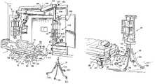
- FIG. 1is a perspective view of an equipment management system having an equipment support and patient care equipment configured to be mounted in a plurality of locations;
- FIG. 2is a perspective view of the equipment support positioned on a stand adjacent to a patient support;
- FIG. 3is a perspective view similar to that of FIG. 2 showing the equipment support carried by an arm extending from the patient support;
- FIG. 4is another perspective view of the equipment support positioned on a vertically telescoping stand
- FIG. 5is a perspective view of another equipment support having two posts for mounting on post receivers
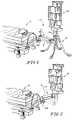
- FIG. 6is a perspective view of an equipment support that is supportable by a motorized lift configured to engage a post of the equipment support;
- FIG. 7is a perspective view similar to that of FIG. 6 showing the motorized lift engaged with the equipment support post;
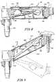
- FIG. 8is a cross-sectional view of the motorized lift of FIGS. 6–7 showing a linear actuator housed therein;
- FIG. 9is a cross-sectional view similar to that of FIG. 8 showing the linear actuator extended such that the motorized lift is in a raised position;
- FIG. 10is a perspective view of a self-deploying stand for carrying an equipment support
- FIG. 11is a perspective view similar to that of FIG. 10 , showing the stand deployed;
- FIG. 12is a perspective view of a stand having a plurality of two-member upper legs connected to single-member lower legs;
- FIG. 13is a perspective view of the stand of FIG. 12 in the collapsed state
- FIG. 14is a top view of an equipment support mounted on a patient support so as to permit passage through an elevator door;
- FIG. 15is another embodiment of a telescoping stand.
- a patient care equipment management system 10shown in FIG. 1 , comprises an equipment support 16 that can be carried or supported by at least one of a patient support 12 , a stand 18 , a support arm 20 , and a wall mount 22 .
- equipment support 16can be supported interchangeably by patient support 12 , stand 18 , support arm 20 , and wall mount 22 .
- patient support 12is illustratively shown in FIG. 1 as a transportable hospital bed for supporting patient 14 , other patient supports are within the scope of the disclosure and can be substituted for the illustrated embodiment.
- patient support 12could be a stretcher, a surgical table, a wheel chair, or any other medical device on which a patient may be supported.
- equipment support 16carries a display and a plurality of monitors for monitoring the status of patient 14 .
- equipment support 16carries a display and a plurality of monitors for monitoring the status of patient 14 .
- other medical devicesmay be carried by or incorporated into equipment support 16 as desired for the care of patient 14 .
- An additional equipment support 24may be provided, as can be seen in FIG. 1 , and may or may not have the features described herein.
- Patient support 12illustratively includes a base 26 (typically including a base frame hidden in whole or in part by a shroud), a patient-support deck 28 supporting a mattress 30 , and an intermediate frame 32 .
- Linkage 34connects intermediate frame 32 to base 26 ; the linkage 34 is power driven thereby permitting movement of patient-support deck 28 and intermediate frame 32 relative to base 26 .
- Intermediate frame 32illustratively includes head-end frame member 36 , which is configured to extend horizontally beyond the periphery of patient-support deck 28 such that certain items can be mounted thereon, including, for example, push handles 38 and corner bumpers 40 , as shown in FIG. 1 .
- Patient support 12has a longitudinal axis.
- Push handles 38are illustratively configured to respond to urges from a caregiver, including pushing or pulling forces exerted on handles 38 . Such pushing or pulling of handles 38 causes handles 38 to act upon respective force sensors interposed between handles 38 and frame member 36 .
- the force sensorsmay comprise, for example, load cells (not shown) that are housed in patient support 12 and that sense the force applied to handles 38 .
- the load cellssend signals to a motorized traction device (not shown) for propelling the patient support 12 , as is disclosed further in U.S. Publication Number 2002/0088055 A1, incorporated herein by reference.
- push handles 38may alternatively comprise standard-mount handles, or push handles 38 may be omitted from patient support 12 .
- An engagersuch as illustrative support arm 42
- Support arm 42is illustratively pivotably mounted to frame member 36 such that support arm 42 pivots about axis 44 . It should be understood, however, that other constructions for pivotably mounting support arm 42 to frame member 36 are within the scope of the disclosure.
- Support arm 42illustratively includes a proximal end 46 that is coupled to frame member 36 and a distal end 48 that is spaced apart from proximal end 46 .
- a post receiver 50is illustratively mounted to distal end 48 of support arm 42 .
- Post receiver 50is configured to engage a downwardly pointing post 52 located on equipment support 16 .
- post 52is conical frustum shaped at lower end 54 , facilitating engagement between post receiver 50 and post 52 even when alignment between the two is slightly off. It should be understood, however, that other approaches by which support arm 42 engages and supports equipment support 16 are within the scope of the disclosure.
- support arm 42could have a post mounted on distal end 48 , while equipment support 16 could have a post receiver.
- support arm 42could have a first coupler and equipment support could have a second, corresponding coupler.
- FIG. 3shows the illustrated embodiment of the support arm 42 engaging and supporting equipment support 16 .
- Post receiver 50 on distal end 48 of support arm 42is brought into engagement with lower end 54 of post 52 by raising patient-support deck 28 and intermediate frame 32 relative to base 26 .
- support arm 42raises with frame member 36 and intermediate frame 32 , thereby moving post receiver 50 toward engagement with post 52 .
- support arm 42can fully support equipment support 16 , and collapsible legs 56 of stand 18 need not balance nor support the weight of equipment support 16 . Therefore, as support arm 42 continues to raise with intermediate frame 32 , legs 56 begin to draw in closer toward each other as a result of the force of gravity pulling the legs downwardly, as can be seen in FIG. 3 .
- support arm 42is pivotably mounted to frame member 36 , and is pivotable between a substantially longitudinally extending position relative to the patient support, shown in FIGS. 2–3 , and a substantially laterally extending position, as shown in FIG. 14 . Furthermore, as can be seen in FIGS. 2–3 , support arm 42 has a stepped configuration and is formed such that distal end 48 of support arm 42 is lower in elevation than proximal end 46 of support arm 42 .
- Such pivotable mountingpermits distal end 48 of support arm 42 to pivot to a position below patient support deck 28 , allowing equipment support 16 to be brought in sufficiently close to a side of patient support 12 such that equipment support 16 and patient support 12 having a width A can fit into an elevator door having a width B (commonly a standard of 48′′ wide) as shown in FIG. 14 .
- legs 56are illustratively lifted a sufficient height off of the floor such that elevator and door thresholds can be cleared during transport without contacting legs 56 .
- patient-support deck 28is lowered in relation to base 26 , and likewise intermediate frame 32 and frame member 36 lower with patient-support deck 28 .
- Support arm 42lowers as frame member 36 lowers, and foot pads 58 on legs 56 contact the floor.
- each foot pad 58contacts the floor, an outer edge of each foot pad 58 contacts first, urging foot pads 58 and their respective legs 56 outwardly toward the deployed position, shown in FIG. 2 .
- post receiver 50disengages from post 52 after frame 32 is lowered by a sufficient amount, leaving equipment support 16 free-standing, as can be seen in FIG. 2 .
- foot pads 58each include a castor wheel (not shown) housed in the foot pad 58 .
- the castor wheelis disclosed to be near the outer edge of the foot pad 58 such that it is the first to contact the floor when equipment support 16 is lowered from its transport position, thereby facilitating deployment of the legs 56 .
- synthetic footpadscomprised of a material that glides over the floor, rather than having footpads with castor wheels.
- castors 60may be substituted for the foot pads, as can be seen in FIG. 1 .
- Legs 56may or may not be collapsible.
- FIGS. 4–13 and 15show alternative embodiments of various elements of an equipment management system.
- FIG. 4shows a mount post 64 that extends below equipment support 16 to engage a post receiver 66 on stand 62 .
- patient support device 12also includes a post receiver 68 configured to receive end 70 of mount post 64 .
- end 70is positioned over post receiver 68 and release pedal 72 is depressed on the base of stand 62 .
- End 70 of mount post 64is illustratively conical frustum shaped.
- Release pedal 72illustratively releases a pneumatic piston inside telescoping column 74 of stand 62 , thereby allowing for column 74 to retract under its own weight so that end 70 of mount post 64 can engage an aperture formed in post receiver 68 .
- stand 162comprises a telescoping column 164 that telescopes relative to base 166 .
- a bearing system having bearings 168facilitates telescoping movement in the direction of arrow 170 .
- a control pendant(not shown) can be attached with a cord, the control pendant actuating telescoping movement of the stand 162 .
- An emergency stop button 172is disclosed for overriding or halting the telescoping movement.
- a Linak LA 31 linear actuatoris housed internally in the telescoping column 164 , and a Linak “Jumbo” battery pack and Linak “Jumbo” control box are positioned inside housing 174 , mounted on the exterior of telescoping column 164 .
- telescoping stand 162may have between 30.48 and 45.72 cm of telescoping movement.
- a handle 176is also provided for horizontal movement of stand 162 .
- Post receiver 66illustratively comprises a substantially C-shaped cross-section that permits the passage of end 70 (shown in FIG. 4 ) therethrough, while being capable of engaging a collar 76 on mount post 64 . Therefore, once end 70 is in place, post receiver 66 of stand 62 can be lowered below collar 76 and disengaged from mount post 64 , permitting stand 62 to be moved away from patient support device 12 . It should be understood that other embodiments and coupling mechanisms are within the scope of the disclosure, including the use of a protrusion instead of a collar.
- Post receiver 68may be fixedly mounted on a patient support 12 , or it may be horizontally movable relative to the patient support 12 .
- Post receiver 68may be located at any number of positions, including at the side, head end, center, or corner of patient support 12 .
- post receiver 66can engage end 70 below collar 76 , and lift pedal 78 can be actuated (illustratively pumped up and down) to extend telescoping column 74 upwardly to engage collar 76 , lifting equipment support 16 off of patient support device 12 .
- FIG. 5shows an equipment support 80 having two posts 82 configured to mate with post receivers 84 coupled to frame member 36 .
- a selected one of posts 82is inserted into a selected post receiver 84 , and is pivotable about an axis coaxial with the selected post 82 .
- post receiverson a head end of a patient support
- mount post receivers on other portions of the bed for equipment support placement at a side or foot end of a bedIt is also within the scope of the disclosure to utilize a plurality of post receivers simultaneously—for either multiple equipment supports or for an equipment support that comprises spaced apart posts that simultaneously are supported by equally spaced apart post receivers.
- a support armcan have an elbow or pivot joint (not shown) for further range of motion of a supported equipment support 16 about a second parallel axis.
- FIGS. 10–13show additional embodiments of a stand.
- FIGS. 10–11show a stand 86 having a plurality of legs 88 linked via linkage 90 to a central hub 92 .
- Central hub 92is configured to slide vertically on a centrally located post 94 , and is biased toward the transport position by spring 96 .
- a deployment-assist tube 98is sleeved over post 94 , such that post 94 and tube 98 are coaxial. Deployment of legs 88 occurs in the following fashion. As a result of the bias of spring 96 , legs 88 remain in their transport position, shown in FIG. 10 , unless outside forces act upon stand 86 .
- stand 86When it is desired to deploy legs 88 , stand 86 is pushed toward the floor such that deployment-assist tube 98 contacts the floor and begins to move axially relative to post 94 . Such axial movement of tube 98 relative to post 94 causes tube 98 to urge hub 92 vertically upwardly on post 94 , thereby moving linkage 90 , as can be seen in FIG. 11 .
- Each linkage 90is pivotably mounted on one end to hub 92 , and on the other end to a central portion of a leg 88 .
- stand 86In the deployed position, shown in FIG. 11 , stand 86 is maintained in the deployed position by the weight of the equipment support that would be mounted on stand 86 . Once equipment support is lifted, legs 88 withdraw to the transport position as a result of the bias of spring 96 .
- Foot pads 100may be castors, rubber feet, slidable polymeric pads, or any other foot pad known in the art.
- FIGS. 12–13show another embodiment for a stand 102 .
- Stand 102comprises a plurality of legs 104 , each leg 104 having a four-bar linkage including a knee joint 106 .
- Each leg 104has a two-member upper portion 108 connected at knee joint 96 to a single-member lower portion 110 . By spacing apart the connection of the two members to the single member, legs 104 of stand 102 extend farther out when deployed, covering a larger footprint with comparatively shorter legs.
- foot pads 112 coupled to distal ends of legs 104have a polymeric composition, and are configured to slide relative to the floor and thereby facilitate the deployment of legs 104 when foot pads 112 come into contact with the floor.
- FIGS. 6–9Another embodiment for a support arm 114 extending from a patient support 12 is shown in FIGS. 6–9 .
- Such an embodimentcan be used on any patient support, but is particularly useful on patient supports 12 having fixed intermediate frames that do not move relative to the base of the patient support 12 and that may carry headboards (not shown).
- a 4-bar motorized lift 116is provided, the lift 116 illustratively having actuator buttons 118 located thereon which can be depressed by a caregiver desiring to either lower or raise equipment support 16 relative to patient support 12 .
- motorized lift 116comprises a top frame member 120 and a bottom frame member 122 , each frame member illustratively being a U-shaped metal beam.
- a patient-support mount 124illustratively includes a post 126 for insertion into a post receiver 128 (visible in FIGS. 6 – 7 ).
- motorized lift 116could alternatively be directly mounted on a frame member of patient support 12 .
- Frame members 120 , 122are each illustratively pivotably attached to patient-support mount 124 at one end via pins 130 , 132 . At the other end, frame members 120 , 122 are pivotably attached to a post receiver 134 via pins 136 , 138 .
- a linear actuator 140is illustratively coupled at one end to bottom frame member 122 via pin 132 , and at the other end to top frame member 120 via pin 136 .
- Linear actuator 140is illustratively an electrically powered linear motor, however, it is within the scope of the disclosure to utilize any electric, pneumatic, gas powered, or other type of motor that is capable of lifting one end of a motorized lift relative to the other end.
- Such an illustrative linear actuatormay be commercially available from Linak® as model number LA28. Linak is headquartered in Nordborg, Denmark.
- pin 136(and consequently post receiver 134 ) is moved away from pin 132 (which is connected to patient-support mount 124 ), therefore motorized lift 116 is moved from a lowered position, such as the phone shown in phantom in FIG. 9 , to a raised position, as shown in dark lines in FIG. 9 .
- post receiver 134is caused to remain oriented so as to provide a substantially vertical support for a post 142 , as seen in FIG. 9 .
- equipment support 16can be mounted on a telescoping arm 20 that extends from a wall.
- Telescoping arm 20may comprise a mount end 144 that is pivotable about a vertical axis 146 , and a equipment-support end 148 .
- Arm 120may include a first segment 150 and a second segment 152 that telescopes horizontally into and out of segment 150 .
- arm 20may be configured so that equipment support 16 is rotatable relative to telescoping arm 20 .
- arm 20is configured such that equipment support 16 can be positioned at any location alongside patient support 12 .
- Equipment support 16is illustratively mounted on a column 154 which extends downwardly from the distal end of arm 20 .
- Lower portion 156 of column 154is illustratively vertically movable relative to arm 20 such that equipment support 16 can be vertically raised and lowered and selectively docked on either post receiver 50 , stand 18 , or wall mount 22 .
- Posts 52 and 160 of equipment support 16can be manufactured in various sizes as required by the application. In some applications, only a single post may be required.
- wall mount 22is C-shaped and is attached to an inner wall of cabinet 158 .
Landscapes
- Health & Medical Sciences (AREA)
- Engineering & Computer Science (AREA)
- General Engineering & Computer Science (AREA)
- Life Sciences & Earth Sciences (AREA)
- Animal Behavior & Ethology (AREA)
- General Health & Medical Sciences (AREA)
- Public Health (AREA)
- Veterinary Medicine (AREA)
- Mechanical Engineering (AREA)
- Nursing (AREA)
- Biomedical Technology (AREA)
- Vascular Medicine (AREA)
- Anesthesiology (AREA)
- Heart & Thoracic Surgery (AREA)
- Hematology (AREA)
- Accommodation For Nursing Or Treatment Tables (AREA)
Abstract
Description
Claims (20)
Priority Applications (2)
| Application Number | Priority Date | Filing Date | Title |
|---|---|---|---|
| US11/422,476US7216382B2 (en) | 2003-03-18 | 2006-06-06 | Patient care equipment management system |
| US11/737,298US7735788B2 (en) | 2003-03-18 | 2007-04-19 | Patient care equipment management system |
Applications Claiming Priority (5)
| Application Number | Priority Date | Filing Date | Title |
|---|---|---|---|
| US45562103P | 2003-03-18 | 2003-03-18 | |
| US51075603P | 2003-10-13 | 2003-10-13 | |
| PCT/US2004/008162WO2004082554A2 (en) | 2003-03-18 | 2004-03-17 | Patient care equipment management system |
| US10/802,289US7065812B2 (en) | 2003-03-18 | 2004-03-17 | Patient care equipment management system |
| US11/422,476US7216382B2 (en) | 2003-03-18 | 2006-06-06 | Patient care equipment management system |
Related Parent Applications (1)
| Application Number | Title | Priority Date | Filing Date |
|---|---|---|---|
| US10/802,289ContinuationUS7065812B2 (en) | 2003-03-18 | 2004-03-17 | Patient care equipment management system |
Related Child Applications (1)
| Application Number | Title | Priority Date | Filing Date |
|---|---|---|---|
| US11/737,298ContinuationUS7735788B2 (en) | 2003-03-18 | 2007-04-19 | Patient care equipment management system |
Publications (2)
| Publication Number | Publication Date |
|---|---|
| US20060207026A1 US20060207026A1 (en) | 2006-09-21 |
| US7216382B2true US7216382B2 (en) | 2007-05-15 |
Family
ID=39929931
Family Applications (3)
| Application Number | Title | Priority Date | Filing Date |
|---|---|---|---|
| US10/802,289Expired - LifetimeUS7065812B2 (en) | 2003-03-18 | 2004-03-17 | Patient care equipment management system |
| US11/422,476Expired - LifetimeUS7216382B2 (en) | 2003-03-18 | 2006-06-06 | Patient care equipment management system |
| US11/737,298Expired - LifetimeUS7735788B2 (en) | 2003-03-18 | 2007-04-19 | Patient care equipment management system |
Family Applications Before (1)
| Application Number | Title | Priority Date | Filing Date |
|---|---|---|---|
| US10/802,289Expired - LifetimeUS7065812B2 (en) | 2003-03-18 | 2004-03-17 | Patient care equipment management system |
Family Applications After (1)
| Application Number | Title | Priority Date | Filing Date |
|---|---|---|---|
| US11/737,298Expired - LifetimeUS7735788B2 (en) | 2003-03-18 | 2007-04-19 | Patient care equipment management system |
Country Status (4)
| Country | Link |
|---|---|
| US (3) | US7065812B2 (en) |
| EP (1) | EP1605887A2 (en) |
| CA (1) | CA2517889A1 (en) |
| WO (1) | WO2004082554A2 (en) |
Cited By (22)
| Publication number | Priority date | Publication date | Assignee | Title |
|---|---|---|---|---|
| US20060031989A1 (en)* | 2004-08-03 | 2006-02-16 | Graham Mark A | Equipment support rail for hospital bed |
| US20060073713A1 (en)* | 2004-09-22 | 2006-04-06 | Chance Richard W | Patient flatwall system |
| US20060242763A1 (en)* | 2003-10-13 | 2006-11-02 | Graham Mark A | Transferable patient care equipment support |
| US20070007418A1 (en)* | 2005-05-02 | 2007-01-11 | Lubbers David P | Brake system for wall arm |
| US20070138354A1 (en)* | 2003-10-13 | 2007-06-21 | Graham Mark A | Patient care equipment support lock |
| US20070251014A1 (en)* | 2003-03-18 | 2007-11-01 | Newkirk David C | Radial arm system for patient care equipment |
| US20080048091A1 (en)* | 2006-07-18 | 2008-02-28 | Aloka Co., Ltd. | Ultrasound diagnosis apparatus |
| US20080234555A1 (en)* | 2007-03-23 | 2008-09-25 | Stryker Corporation | Patient care system |
| US20090314923A1 (en)* | 2006-09-28 | 2009-12-24 | Wojciech Timoszyk | Medical equipment transfer arrangement |
| US7735788B2 (en) | 2003-03-18 | 2010-06-15 | Hill-Rom Services, Inc. | Patient care equipment management system |
| US7770860B1 (en) | 2005-11-10 | 2010-08-10 | Modular Services Company | Medical service system on articulating arm with electromagnetic brakes |
| US7845601B1 (en) | 2006-11-09 | 2010-12-07 | Modular Services Company | Medical equipment transport system |
| US8006332B2 (en) | 2005-12-19 | 2011-08-30 | Stryker Corporation | Hospital bed |
| US20110277240A1 (en)* | 2008-05-01 | 2011-11-17 | Veso Tijanic | Connector and medical device system incorporating same |
| US20130181100A1 (en)* | 2007-02-27 | 2013-07-18 | Streamline, Inc. | Transformable intravenous pole |
| US8733719B2 (en) | 2010-11-12 | 2014-05-27 | Wildcard Enterprises Llc | Method and apparatus for use in management of medical intravenous pole assemblies |
| WO2014144695A1 (en)* | 2013-03-15 | 2014-09-18 | Streamline, Inc. | Transformable intravenous pole and boom combination and method thereof |
| US20150157522A1 (en)* | 2007-02-27 | 2015-06-11 | Streamline, Inc. | Transformable intravenous pole |
| US9707334B2 (en) | 2013-03-15 | 2017-07-18 | Skytron, Llc | Transformable intravenous pole and boom combination and method thereof |
| US9883978B2 (en) | 2015-04-16 | 2018-02-06 | Skytron, Llc | Docking systems for medical devices and related devices |
| US10582981B2 (en) | 2016-02-02 | 2020-03-10 | Stryker Corporation | Accessory support and coupling systems for an accessory support |
| US11067221B1 (en)* | 2019-05-15 | 2021-07-20 | Robert F. Johnson | Hand hygiene system and method of use |
Families Citing this family (81)
| Publication number | Priority date | Publication date | Assignee | Title |
|---|---|---|---|---|
| AU2002309987A1 (en)* | 2001-05-25 | 2002-12-09 | Hill-Rom Services, Inc. | Modular patient room |
| JP3898150B2 (en)* | 2002-10-17 | 2007-03-28 | 古河機械金属株式会社 | Lifting device for TV camera |
| US20070069093A1 (en)* | 2003-10-13 | 2007-03-29 | Hill-Rom Services, Inc. | Patient care equipment support system |
| US7849537B2 (en)* | 2003-10-13 | 2010-12-14 | Hill-Rom Services, Inc. | Equipment support having rotatable bumpers and hooks |
| WO2005037166A2 (en)* | 2003-10-13 | 2005-04-28 | Hill-Rom Services, Inc. | Brake system for patient care equipment support arm |
| US7556619B2 (en) | 2004-04-16 | 2009-07-07 | Medrad, Inc. | Fluid delivery system having a fluid level sensor and a fluid control device for isolating a patient from a pump device |
| US20070126318A1 (en)* | 2004-10-14 | 2007-06-07 | Hamberg Stephen R | Service head with accessory tracks |
| US7884735B2 (en) | 2005-02-11 | 2011-02-08 | Hill-Rom Services, Inc. | Transferable patient care equipment support |
| TW200701968A (en)* | 2005-05-06 | 2007-01-16 | Steris Inc | Transfer system and transfer device |
| US8069513B2 (en)* | 2006-01-19 | 2011-12-06 | Hill-Rom Services, Inc. | Patient support apparatus having auto contour |
| US7997592B2 (en)* | 2006-06-26 | 2011-08-16 | Darren Stout | Gurney clamp, detachable equipment stand and associated transport cart |
| US7661641B2 (en)* | 2006-12-22 | 2010-02-16 | Linvatec Corporation | Medical equipment transfer system |
| WO2008085698A2 (en) | 2007-01-03 | 2008-07-17 | Firefly Medical, Inc. | Integrated infusion management system |
| US8104729B2 (en)* | 2007-03-09 | 2012-01-31 | Hill-Rom Services, Inc. | Transferable patient care equipment support |
| JP2008241903A (en)* | 2007-03-26 | 2008-10-09 | Bank Of Tokyo-Mitsubishi Ufj Ltd | Stand for display device |
| NL2000571C2 (en)* | 2007-04-03 | 2008-10-06 | Ihb B V | Stand for e.g. blood infusion bags or pumps, secured to holders by fasteners movable in vertical direction |
| US7865983B2 (en) | 2007-04-26 | 2011-01-11 | Hill-Rom Services, Inc. | Patient care equipment support transfer system |
| ITPD20070268A1 (en)* | 2007-08-03 | 2009-02-04 | Manfrotto Lino & C Spa | STATION IN COLUMN, PARTICULARLY FOR THE SUPPORT OF LIGHTING PLANTS AND SOUND SYSTEMS |
| US7798456B2 (en)* | 2007-08-21 | 2010-09-21 | Hill-Rom Services, Inc. | Transferable patient care equipment support |
| US7748672B2 (en) | 2007-09-07 | 2010-07-06 | Hill-Rom Services, Inc. | Transferable patient care equipment support |
| DE102007043431A1 (en)* | 2007-09-12 | 2009-03-19 | Maquet Gmbh & Co. Kg | Transport trolley for the patient support surface of a surgical table |
| DE102007043232B4 (en)* | 2007-09-13 | 2009-06-04 | Dräger Medical AG & Co. KG | Medical workplace for patients |
| US8196874B2 (en)* | 2007-10-12 | 2012-06-12 | Maxtec, Llc | Storable intravenous stands |
| WO2009073789A2 (en)* | 2007-12-04 | 2009-06-11 | Draeger Medical Systems, Inc. | Modular warming therapy device |
| US20110214673A1 (en)* | 2008-05-08 | 2011-09-08 | Edward Masionis | Portable Life Support Apparatus Ventilator |
| US20100052274A1 (en)* | 2008-08-27 | 2010-03-04 | West Richard L | Cart assemblies for use with blood filtration |
| US20100159415A1 (en)* | 2008-11-23 | 2010-06-24 | Tom Benfield | Dental delivery system |
| US8061664B2 (en)* | 2009-02-13 | 2011-11-22 | A-Dec, Inc. | Base and support system for a patient support apparatus |
| USD630731S1 (en) | 2010-02-05 | 2011-01-11 | Firefly Medical, Inc. | Infusion management system holder |
| US8662458B2 (en) | 2010-02-05 | 2014-03-04 | Firefly Medical, Inc. | Infusion management system and holder |
| WO2011100135A1 (en) | 2010-02-11 | 2011-08-18 | Herman Miller, Inc. | Wall mounted assembly |
| JP2013523528A (en) | 2010-04-07 | 2013-06-17 | アルコン リサーチ, リミテッド | System and method for a caster to respond to an obstacle |
| JP5689949B2 (en) | 2010-04-07 | 2015-03-25 | アルコン リサーチ, リミテッド | System and method for console braking |
| US9089367B2 (en) | 2010-04-08 | 2015-07-28 | Alcon Research, Ltd. | Patient eye level touch control |
| US9528536B2 (en) | 2010-05-10 | 2016-12-27 | Nexxspan Healthcare, Llc | Secure equipment transfer system |
| US8579244B2 (en)* | 2010-05-10 | 2013-11-12 | Lifespan Healthcare, Llc | Secure equipment transfer system |
| US9404616B2 (en) | 2010-05-10 | 2016-08-02 | Nexxspan Healthcare, Llc | Secure equipment transfer system |
| US20120228441A1 (en)* | 2011-03-11 | 2012-09-13 | Rodrigo Ceron | Flexible and retractable support arm for electronic devices |
| US20130001180A1 (en)* | 2011-06-29 | 2013-01-03 | Stout Christopher A | Sterile rack for contraceptive procedure |
| US8827215B2 (en)* | 2011-09-02 | 2014-09-09 | Randall D. Hilton | Systems and methods for securing mobile medical equipment supporter systems to patient transporters |
| US20140064828A1 (en)* | 2011-09-02 | 2014-03-06 | Randall D. Hilton | Systems and Methods for Securing Mobile Medical Equipment Supporter Systems to Patient Transporters with Adjustability |
| US9097384B1 (en)* | 2011-11-30 | 2015-08-04 | Sun Nuclear Corporation | Support apparatus for radiotherapy measurement system |
| US9033162B2 (en) | 2012-02-07 | 2015-05-19 | American Medical Stand LLC | System, method and apparatus for surgical stand |
| US9050460B2 (en) | 2012-05-02 | 2015-06-09 | Sun Nuclear Corporation | System and method for radiation beam measurement normalization |
| EP2856210B1 (en) | 2012-05-29 | 2018-04-25 | Sun Nuclear Corporation | Method and system for calorimetry probe |
| AU2013296136B2 (en) | 2012-07-25 | 2017-11-02 | Rowston, Phillip MR | A medical paraphernalia carrier assembly |
| WO2014150650A1 (en)* | 2013-03-15 | 2014-09-25 | Surgitrac Corporation | Surgical object and fluid monitoring system having highly sensitive and reliable detection of objects being placed in a container |
| US8692140B1 (en)* | 2013-03-15 | 2014-04-08 | Surgitrac Corporation | Surgical object and fluid monitoring system having highly sensitive and reliable detection of objects being placed in a container |
| US9347817B2 (en) | 2013-03-15 | 2016-05-24 | Surgitrac Corporation | Surgical object and comprehensive fluid monitoring system having capability of mobile monitoring and having highly sensitive and reliable detection of objects being placed in a container |
| US8963025B2 (en)* | 2013-03-15 | 2015-02-24 | Surgitrac Corporation | Surgical object and fluid monitoring system having highly sensitive and reliable detection of objects being placed in a container |
| CN105593059B (en) | 2013-07-19 | 2018-07-31 | 萤火虫医疗公司 | Devices for mobility aids and infusion management |
| DE102013223486A1 (en)* | 2013-11-18 | 2015-05-21 | Berchtold Holding AG | operating table |
| US9661923B2 (en)* | 2013-12-31 | 2017-05-30 | John Stephen Lanphear | Table and accessory unit assembly and method of docking accessory unit to table |
| US9480861B2 (en) | 2014-04-03 | 2016-11-01 | Sun Nuclear Corporation | Dosimetry for radiotherapy treatment verification |
| US9839742B2 (en)* | 2014-05-16 | 2017-12-12 | Pryor Products, Inc. | Bed transportable medical stand mount |
| WO2016100739A1 (en) | 2014-12-19 | 2016-06-23 | Sun Nuclear Corporation | Radiation therapy dose calculation |
| USD791937S1 (en) | 2015-02-10 | 2017-07-11 | Firefly Medical, Inc. | Infusion management and mobility assistance device |
| US9468292B2 (en)* | 2015-03-09 | 2016-10-18 | Target Brands, Inc. | Shelving connector and associated storage system and method |
| USD784797S1 (en) | 2015-03-09 | 2017-04-25 | Target Brands, Inc. | Shelving connector |
| WO2016160344A1 (en) | 2015-03-27 | 2016-10-06 | Firefly Medical, Inc. | Patient mobility assessment device |
| US10617891B2 (en) | 2015-04-23 | 2020-04-14 | Sun Nuclear Corporation | Radiation detector calibration |
| CN105030337A (en)* | 2015-07-14 | 2015-11-11 | 南京鼎瑞医疗器械有限公司 | Multifunctional medical pendant bridge |
| EP3361950A4 (en)* | 2015-10-13 | 2019-03-20 | HyperMed Imaging, Inc. | COMPACT LIGHT SENSORS FOR SURGICAL APPLICATIONS AND SHOCK DETECTION |
| US10258424B2 (en) | 2016-02-22 | 2019-04-16 | Nexxspan Healthcare, Llc | Sacrificial mechanical link |
| US10258524B2 (en) | 2016-02-22 | 2019-04-16 | Nexxspan Healthcare, Llc | Transfer system with sacrificial mechanical link |
| US10767811B2 (en)* | 2016-02-24 | 2020-09-08 | Stryker Corporation | Brake control system for suspensions |
| US10893988B2 (en) | 2016-05-26 | 2021-01-19 | Stryker Corporation | Patient support systems and methods for docking, transporting, sterilizing, and storing patient support decks |
| WO2018023049A1 (en) | 2016-07-28 | 2018-02-01 | Sun Nuclear Corporation | Beam angle direction determination |
| WO2018160763A1 (en) | 2017-02-28 | 2018-09-07 | Sun Nuclear Corporation | Radiation therapy treatment verification with electronic portal imaging device transit images |
| US11007102B2 (en)* | 2017-08-22 | 2021-05-18 | Stryker Corporation | Patient transport system |
| EP3732753B1 (en) | 2017-12-27 | 2024-02-28 | Drägerwerk AG & Co. KGaA | System of mateable connectors and rack mount |
| US11278744B2 (en) | 2018-09-28 | 2022-03-22 | Sun Nuclear Corporation | Systems and methods to account for tilt of a radiation measurement system |
| US10611391B1 (en)* | 2018-10-05 | 2020-04-07 | Corindus, Inc. | Mobile support and storage system for a medical device |
| CN109731199A (en)* | 2019-03-09 | 2019-05-10 | 柴红勇 | A kind of Multifunctional internal medicine clinic breathing equipment |
| US11600004B2 (en) | 2019-07-10 | 2023-03-07 | Sun Nuclear Corporation | Image-based radiation therapy quality assurance |
| US11378700B2 (en) | 2019-07-10 | 2022-07-05 | Sun Nuclear Corporation | Scintillator-based radiation therapy quality assurance |
| US12011616B2 (en) | 2019-07-10 | 2024-06-18 | Sun Nuclear Corporation | Image-based radiation therapy quality assurance |
| AU2020363641A1 (en) | 2019-10-08 | 2022-04-14 | Nexxspan Healthcare, Llc | Transfer device docking indicator |
| EP4110256A4 (en)* | 2020-02-28 | 2024-03-27 | Technologies CGC Inc. | Coupling systems for releasably coupling equipment to a patient transport system |
| US12438349B2 (en) | 2022-04-13 | 2025-10-07 | Angel Medical LLC | Smart IV pole |
| US12201850B2 (en) | 2022-06-16 | 2025-01-21 | Sun Nuclear Corporation | High dose rate radiation therapy systems and dosimetry |
Citations (111)
| Publication number | Priority date | Publication date | Assignee | Title |
|---|---|---|---|---|
| US383815A (en) | 1888-05-29 | William w | ||
| US1290809A (en) | 1917-10-25 | 1919-01-07 | Florence B Truax | Portable irrigating-stand. |
| US1490650A (en) | 1920-09-08 | 1924-04-15 | Mccallum Company | Plant stand |
| US1919114A (en) | 1931-07-07 | 1933-07-18 | Ley George Albert | Lamp stand |
| US2470524A (en) | 1946-07-13 | 1949-05-17 | Jarvis & Jarvis Inc | Intravenous stand attachment for wheel stretchers |
| US2497425A (en) | 1950-02-14 | Flue damper with latching means | ||
| US2673771A (en) | 1952-02-06 | 1954-03-30 | Josephine E Krewson | Infusion carrier for attachment to hospital stretchers |
| US2696963A (en) | 1951-06-13 | 1954-12-14 | Trephine Instr Inc | Portable intravenous fluid carrier |
| US3004743A (en) | 1958-09-15 | 1961-10-17 | Harry J Wenger | Music stands |
| FR1292174A (en) | 1961-06-15 | 1962-04-27 | Amalgamated Dental Co Ltd | dental care equipment |
| US3213877A (en) | 1962-07-18 | 1965-10-26 | Air Reduction | Retractable column for medical service outlets |
| GB1061383A (en) | 1962-08-24 | 1967-03-08 | Jack Edward N Fa | Improvements in or relating to operating theatre hatch |
| US3431937A (en) | 1965-09-08 | 1969-03-11 | Chemetron Corp | Medical service unit |
| US3552577A (en) | 1969-10-02 | 1971-01-05 | Cryogenic Technology Inc | Apparatus for transporting liquids |
| US3674294A (en) | 1970-03-16 | 1972-07-04 | Arthur J Kirkham | Clamping telescopic tubes |
| US3709556A (en) | 1970-10-16 | 1973-01-09 | E Allard | Telescoping i v pole attachment and wheel chairs |
| US3814023A (en) | 1973-06-19 | 1974-06-04 | New Standard Co Inc | Vertically adjustable suspension assembly |
| US3931452A (en) | 1972-09-26 | 1976-01-06 | Agne Lars Harry Nilsson | Device for attachment of ceiling-supended equipment |
| US4005844A (en) | 1975-08-25 | 1977-02-01 | Stryker Corporation | Solution bottle holder |
| US4094484A (en) | 1976-03-13 | 1978-06-13 | W. Vinten Limited | Balanced portable pedestals |
| US4113222A (en) | 1977-05-31 | 1978-09-12 | Frinzel Jerry C | Intravenous pole |
| US4190224A (en) | 1977-04-25 | 1980-02-26 | Leblanc Edgar J | Intravenous pole holder |
| US4225104A (en) | 1978-11-20 | 1980-09-30 | Larson Godfrey R | Handle for mobile intravenous stand |
| US4262874A (en) | 1979-03-19 | 1981-04-21 | William Seigh | Plate hanger |
| USD260816S (en) | 1979-01-08 | 1981-09-15 | Baxter Travenol Laboratories, Inc. | Intravenous equipment support or similar article |
| US4339104A (en) | 1980-04-23 | 1982-07-13 | Weidman Marilyn V | Floor stand mounted mirror |
| US4378014A (en) | 1981-03-27 | 1983-03-29 | Elkow Robert D | Apparatus for and method of administering intravenous fluid |
| US4489454A (en) | 1980-01-29 | 1984-12-25 | Thompson James C | Portable hinged transducer carrier |
| US4511157A (en) | 1982-07-19 | 1985-04-16 | St. Joseph's Hospital And Medical Center | Apparatus for facilitating intravenous feeding during transportation of patient |
| US4511158A (en) | 1982-08-27 | 1985-04-16 | Mt. Sinai Medical Center Of Greater Miami | Intravenous infusion pole attachment |
| US4559036A (en) | 1983-12-14 | 1985-12-17 | Wunsch Richard E | Apparatus for controlling administration of multiple intravenous solutions and medications |
| US4600209A (en) | 1984-07-02 | 1986-07-15 | Kerr Jr Robert L | Transport support for freestanding umbilical accessory |
| US4616797A (en) | 1984-08-13 | 1986-10-14 | Mina Manufacturing, Inc. | Adjustable support assembly |
| EP0215212A2 (en) | 1985-09-18 | 1987-03-25 | TRILUX-LENZE GmbH & Co. KG | Supply unit for a medical nursing post |
| USD289604S (en) | 1985-01-28 | 1987-05-05 | Hill-Rom Company, Inc. | Equipment support hub assembly |
| US4691397A (en) | 1986-06-09 | 1987-09-08 | Netzer Ronald G | Life support carrying apparatus |
| US4718892A (en) | 1986-03-10 | 1988-01-12 | Yung Ho Liu | Drip infusion system |
| US4725027A (en) | 1986-09-23 | 1988-02-16 | Joseph Bekanich | Intravenous equipment support |
| US4729576A (en) | 1986-03-20 | 1988-03-08 | Roach Keyton W | Device for tandem movement of IV-pole and gurney |
| US4744536A (en) | 1986-06-25 | 1988-05-17 | Icu Medical, Inc. | Collapsable pole and stand combination |
| US4756706A (en) | 1985-01-23 | 1988-07-12 | American Hospital Supply Corporation | Centrally managed modular infusion pump system |
| US4795122A (en) | 1986-07-15 | 1989-01-03 | Cleveland Clinic Foundation | Patient equipment transport and support system |
| US4801815A (en) | 1987-11-12 | 1989-01-31 | The Boc Group, Inc. | Autostop mechanism for pendant assembly |
| US4879798A (en) | 1986-07-15 | 1989-11-14 | The Cleveland Clinic Foundation | Method for patient equipment transport and support system |
| US4892279A (en) | 1987-05-04 | 1990-01-09 | Polymedical Technologies, Inc. | Fully portable medical I.V. equipment stand/pole |
| US4901967A (en) | 1986-07-15 | 1990-02-20 | The Cleveland Clinic Foundation | Patient equipment transport and support system |
| US4905882A (en) | 1988-12-28 | 1990-03-06 | Ross Judy L | Neck engaging support for medical device |
| US4905944A (en) | 1989-01-26 | 1990-03-06 | Baxter International Inc. | Home care intravenous stand |
| US4925444A (en) | 1987-08-07 | 1990-05-15 | Baxter Travenol Laboratories, Inc. | Closed multi-fluid delivery system and method |
| US4945592A (en) | 1988-09-30 | 1990-08-07 | The General Hospital Corporation | Transport system for portable patient care apparatus |
| US4966340A (en) | 1989-04-24 | 1990-10-30 | Hunter Rebecca L | Wheeled stand apparatus for hanging containers of medical fluids |
| US4969768A (en) | 1989-09-28 | 1990-11-13 | Young Robert J | Coupler for IV pole |
| US4997150A (en) | 1987-04-17 | 1991-03-05 | Lifter S.R.L. | Adjustable oleopneumatic support |
| US5016307A (en) | 1990-03-23 | 1991-05-21 | Linda Rebar | Integral stretcher and intravenous fluid carrier/gravity dependent drainage support |
| US5072906A (en) | 1988-01-15 | 1991-12-17 | Hill-Rom Company, Inc. | Hospital bed with pivoting headboard |
| US5078349A (en) | 1990-04-16 | 1992-01-07 | Midmark Corporation | Locking mechanism for an IV pole |
| US5083807A (en) | 1990-12-18 | 1992-01-28 | Church Home & Hospital Of The City Of Baltimore | IV stand coupling device |
| US5094418A (en) | 1990-09-07 | 1992-03-10 | Stryker Corporation | IV pole |
| US5108064A (en) | 1989-11-10 | 1992-04-28 | F.M.K. Kreuzer Gmbh & Co. Kg | Appliance support |
| US5110076A (en) | 1991-01-14 | 1992-05-05 | Cal-Surgical, Inc. | Adjustable multipole support stand for medical fluids |
| EP0257299B1 (en) | 1986-08-13 | 1992-05-06 | Kreuzer GmbH + Co. OHG | Ceiling support |
| US5112019A (en) | 1991-02-04 | 1992-05-12 | Storz Instrument Company | Motorized IV pole assembly |
| US5125607A (en) | 1991-01-08 | 1992-06-30 | Pryor Products | Stable support stand adapted for flat storage |
| US5135191A (en) | 1991-05-09 | 1992-08-04 | Jagco Corporation | Medical support system |
| US5149036A (en) | 1991-08-29 | 1992-09-22 | Sheehan Gerald F | Device for attaching an IV pole to a hospital bed or the like |
| US5186337A (en) | 1991-08-09 | 1993-02-16 | Hill-Rom Company, Inc. | Pivoted power column |
| US5207642A (en) | 1987-08-07 | 1993-05-04 | Baxter International Inc. | Closed multi-fluid delivery system and method |
| US5219139A (en) | 1992-06-25 | 1993-06-15 | Barnes Hospital | Device for connecting an IV pole to a wheelchair |
| US5224681A (en) | 1990-04-13 | 1993-07-06 | Lundstrom Donald A | Hand releasable locking collar |
| US5306109A (en) | 1991-04-23 | 1994-04-26 | Kreuzer Gmbh & Co. Ohg | Transportable medical apparatus, in particular infusion supply |
| US5319816A (en) | 1992-12-07 | 1994-06-14 | Hill-Rom Company, Inc. | IV rack transferrable from an IV stand to a hospital bed |
| US5326059A (en) | 1992-12-23 | 1994-07-05 | Pryor Products | Quick clamping system |
| US5366191A (en) | 1992-02-19 | 1994-11-22 | Joseph Bekanich | Support apparatus for a patient infusion device |
| US5400995A (en) | 1992-04-15 | 1995-03-28 | Hill-Rom Company, Inc. | IV pole with interior drag brake |
| US5407163A (en) | 1993-11-19 | 1995-04-18 | Hill-Rom Company, Inc. | Sliding IV pole |
| US5421548A (en) | 1994-04-01 | 1995-06-06 | Bennett; James R. | I.V. stand and attachments |
| US5479958A (en) | 1994-05-11 | 1996-01-02 | Dragerwerk Ag | Supply unit for medical treatment instruments |
| US5527125A (en) | 1992-08-17 | 1996-06-18 | Kreuzer Gmbh & Co. Ohg | Transportable medical apparatus, in particular infusion supply apparatus |
| US5588166A (en) | 1995-01-04 | 1996-12-31 | Burnett; John | Medical attachment device |
| US5618090A (en) | 1995-05-12 | 1997-04-08 | Medaes, Inc. | Movable hospital room equipment column |
| US5647491A (en) | 1992-04-15 | 1997-07-15 | Hill-Rom Company, Inc. | IV rack |
| US5657884A (en) | 1996-02-21 | 1997-08-19 | Metaline Products Company Inc. | Display pole support structure |
| US5699988A (en) | 1993-01-19 | 1997-12-23 | St. Francis Research Institute | Coupler clamping apparatus for interconnecting a free-standing, wheeled intravenous pole with mobile patient transfer devices |
| US5704577A (en) | 1995-10-11 | 1998-01-06 | Gordon; Gray J. | Walker-IV stand coupler |
| US5857685A (en) | 1995-08-09 | 1999-01-12 | Phillips; James R. | Support cart apparatus for supporting intravenous fluid dispensing systems |
| US5878536A (en) | 1997-05-28 | 1999-03-09 | The Charlotte-Mecklenburg Hospital Authority | Neonatal infant care headwall |
| US5898961A (en) | 1995-06-07 | 1999-05-04 | Hill-Rom, Inc. | Mobile support unit and attachment mechanism for patient transport device |
| US5924658A (en) | 1998-01-07 | 1999-07-20 | Stryker Corporation | IV pole |
| US5966760A (en) | 1997-01-31 | 1999-10-19 | Hill-Rom, Inc. | Apparatus and method for upgrading a hospital room |
| US5987670A (en) | 1998-04-23 | 1999-11-23 | The General Hospital Corporation | Medical equipment transport system |
| WO2000009061A1 (en) | 1998-08-14 | 2000-02-24 | The General Hospital Corporation Doing Business As Massachussets General Hospital | Transfer system for portable patient care apparatus |
| US6056249A (en) | 1998-02-25 | 2000-05-02 | Fillon, Jr.; Charles W. | Device for allowing a person to be connected to and walk with various medical equipment |
| US6095468A (en) | 1998-03-27 | 2000-08-01 | Hill-Rom, Inc. | Support arm for a service column |
| US6152426A (en) | 1998-11-06 | 2000-11-28 | Von Fange; Eric Eugene | Extensible boom |
| US6155743A (en) | 1998-12-09 | 2000-12-05 | Tay-E Co., Ltd. | Anchoring fixture for holding a musical instrument |
| US6170102B1 (en) | 1997-11-18 | 2001-01-09 | Kreuzer Gmbh & Co. Ohg | Operating equipment |
| US6179260B1 (en) | 1998-06-10 | 2001-01-30 | N. Sean Ohanian | Device for coupling an IV stand to a patient transport |
| US6182662B1 (en) | 1998-07-23 | 2001-02-06 | Mcghee Chad J. | Intravenous transport/support device |
| US6213481B1 (en) | 1998-07-01 | 2001-04-10 | Alm | Assembly consisting of a support structure and of a trolley for transporting equipment |
| EP0943306B1 (en) | 1998-03-19 | 2002-06-26 | TRUMPF Kreuzer Medizin Systeme GmbH + Co. KG | Monitoring and supply device for patients |
| US6431515B1 (en) | 1999-09-21 | 2002-08-13 | Heraeus Med Gmbh | Ceiling-supported suspension means |
| US6434329B1 (en) | 1999-05-13 | 2002-08-13 | L'universite De Montreal | Controllable camera support and system |
| US20030014817A1 (en) | 2001-05-25 | 2003-01-23 | Gallant Dennis J. | Architectural system adaptable to patient acuity level |
| US6553587B1 (en) | 2001-10-25 | 2003-04-29 | Ge Medical Systems Global Technology Company, Llc | Method and apparatus for alignment and orientation of a monitor in a patient support system |
| EP1243900A3 (en) | 2001-03-23 | 2003-06-04 | Fratelli Pettinaroli S.P.A | Optical flowmeter |
| US6725483B2 (en) | 1997-01-31 | 2004-04-27 | Hill-Rom Services, Inc. | Apparatus and method for upgrading a hospital room |
| US20040164220A1 (en)* | 2002-11-13 | 2004-08-26 | Newkirk David C. | Apparatus for carrying medical equipment |
| US20040199996A1 (en) | 2003-03-18 | 2004-10-14 | Newkirk David C. | Radial arm system for patient care equipment |
| US20050000019A1 (en) | 2003-03-18 | 2005-01-06 | Newkirk David C. | Patient care equipment management system |
| US20060031989A1 (en)* | 2004-08-03 | 2006-02-16 | Graham Mark A | Equipment support rail for hospital bed |
| US20060242763A1 (en)* | 2003-10-13 | 2006-11-02 | Graham Mark A | Transferable patient care equipment support |
Family Cites Families (3)
| Publication number | Priority date | Publication date | Assignee | Title |
|---|---|---|---|---|
| DE9204321U1 (en) | 1992-03-31 | 1992-05-21 | Trilux-Lenze Gmbh + Co Kg, 5760 Arnsberg | Medical care station |
| DE19623713B4 (en)* | 1996-06-14 | 2008-06-19 | Robert Bosch Gmbh | Injection valve, in particular for the direct injection of fuel into a combustion chamber of an internal combustion engine |
| DE10340552B4 (en)* | 2003-09-01 | 2015-10-15 | Siemens Aktiengesellschaft | patient support |
- 2004
- 2004-03-17EPEP04757564Apatent/EP1605887A2/ennot_activeWithdrawn
- 2004-03-17WOPCT/US2004/008162patent/WO2004082554A2/enactiveApplication Filing
- 2004-03-17USUS10/802,289patent/US7065812B2/ennot_activeExpired - Lifetime
- 2004-03-17CACA002517889Apatent/CA2517889A1/ennot_activeAbandoned
- 2006
- 2006-06-06USUS11/422,476patent/US7216382B2/ennot_activeExpired - Lifetime
- 2007
- 2007-04-19USUS11/737,298patent/US7735788B2/ennot_activeExpired - Lifetime
Patent Citations (119)
| Publication number | Priority date | Publication date | Assignee | Title |
|---|---|---|---|---|
| US2497425A (en) | 1950-02-14 | Flue damper with latching means | ||
| US383815A (en) | 1888-05-29 | William w | ||
| US1290809A (en) | 1917-10-25 | 1919-01-07 | Florence B Truax | Portable irrigating-stand. |
| US1490650A (en) | 1920-09-08 | 1924-04-15 | Mccallum Company | Plant stand |
| US1919114A (en) | 1931-07-07 | 1933-07-18 | Ley George Albert | Lamp stand |
| US2470524A (en) | 1946-07-13 | 1949-05-17 | Jarvis & Jarvis Inc | Intravenous stand attachment for wheel stretchers |
| US2696963A (en) | 1951-06-13 | 1954-12-14 | Trephine Instr Inc | Portable intravenous fluid carrier |
| US2673771A (en) | 1952-02-06 | 1954-03-30 | Josephine E Krewson | Infusion carrier for attachment to hospital stretchers |
| US3004743A (en) | 1958-09-15 | 1961-10-17 | Harry J Wenger | Music stands |
| FR1292174A (en) | 1961-06-15 | 1962-04-27 | Amalgamated Dental Co Ltd | dental care equipment |
| US3213877A (en) | 1962-07-18 | 1965-10-26 | Air Reduction | Retractable column for medical service outlets |
| GB1061383A (en) | 1962-08-24 | 1967-03-08 | Jack Edward N Fa | Improvements in or relating to operating theatre hatch |
| US3431937A (en) | 1965-09-08 | 1969-03-11 | Chemetron Corp | Medical service unit |
| US3552577A (en) | 1969-10-02 | 1971-01-05 | Cryogenic Technology Inc | Apparatus for transporting liquids |
| US3674294A (en) | 1970-03-16 | 1972-07-04 | Arthur J Kirkham | Clamping telescopic tubes |
| US3709556A (en) | 1970-10-16 | 1973-01-09 | E Allard | Telescoping i v pole attachment and wheel chairs |
| US3931452A (en) | 1972-09-26 | 1976-01-06 | Agne Lars Harry Nilsson | Device for attachment of ceiling-supended equipment |
| US3814023A (en) | 1973-06-19 | 1974-06-04 | New Standard Co Inc | Vertically adjustable suspension assembly |
| US4005844A (en) | 1975-08-25 | 1977-02-01 | Stryker Corporation | Solution bottle holder |
| US4094484A (en) | 1976-03-13 | 1978-06-13 | W. Vinten Limited | Balanced portable pedestals |
| US4190224A (en) | 1977-04-25 | 1980-02-26 | Leblanc Edgar J | Intravenous pole holder |
| US4113222A (en) | 1977-05-31 | 1978-09-12 | Frinzel Jerry C | Intravenous pole |
| US4225104A (en) | 1978-11-20 | 1980-09-30 | Larson Godfrey R | Handle for mobile intravenous stand |
| USD260816S (en) | 1979-01-08 | 1981-09-15 | Baxter Travenol Laboratories, Inc. | Intravenous equipment support or similar article |
| US4262874A (en) | 1979-03-19 | 1981-04-21 | William Seigh | Plate hanger |
| US4489454A (en) | 1980-01-29 | 1984-12-25 | Thompson James C | Portable hinged transducer carrier |
| US4339104A (en) | 1980-04-23 | 1982-07-13 | Weidman Marilyn V | Floor stand mounted mirror |
| US4378014A (en) | 1981-03-27 | 1983-03-29 | Elkow Robert D | Apparatus for and method of administering intravenous fluid |
| US4511157A (en) | 1982-07-19 | 1985-04-16 | St. Joseph's Hospital And Medical Center | Apparatus for facilitating intravenous feeding during transportation of patient |
| US4511158A (en) | 1982-08-27 | 1985-04-16 | Mt. Sinai Medical Center Of Greater Miami | Intravenous infusion pole attachment |
| US4559036A (en) | 1983-12-14 | 1985-12-17 | Wunsch Richard E | Apparatus for controlling administration of multiple intravenous solutions and medications |
| US4600209A (en) | 1984-07-02 | 1986-07-15 | Kerr Jr Robert L | Transport support for freestanding umbilical accessory |
| US4616797A (en) | 1984-08-13 | 1986-10-14 | Mina Manufacturing, Inc. | Adjustable support assembly |
| US4756706A (en) | 1985-01-23 | 1988-07-12 | American Hospital Supply Corporation | Centrally managed modular infusion pump system |
| USD289604S (en) | 1985-01-28 | 1987-05-05 | Hill-Rom Company, Inc. | Equipment support hub assembly |
| EP0215212A2 (en) | 1985-09-18 | 1987-03-25 | TRILUX-LENZE GmbH & Co. KG | Supply unit for a medical nursing post |
| US4718892A (en) | 1986-03-10 | 1988-01-12 | Yung Ho Liu | Drip infusion system |
| US4729576A (en) | 1986-03-20 | 1988-03-08 | Roach Keyton W | Device for tandem movement of IV-pole and gurney |
| US4691397A (en) | 1986-06-09 | 1987-09-08 | Netzer Ronald G | Life support carrying apparatus |
| US4744536A (en) | 1986-06-25 | 1988-05-17 | Icu Medical, Inc. | Collapsable pole and stand combination |
| US4901967A (en) | 1986-07-15 | 1990-02-20 | The Cleveland Clinic Foundation | Patient equipment transport and support system |
| US4879798A (en) | 1986-07-15 | 1989-11-14 | The Cleveland Clinic Foundation | Method for patient equipment transport and support system |
| US4795122A (en) | 1986-07-15 | 1989-01-03 | Cleveland Clinic Foundation | Patient equipment transport and support system |
| EP0257299B1 (en) | 1986-08-13 | 1992-05-06 | Kreuzer GmbH + Co. OHG | Ceiling support |
| US4725027A (en) | 1986-09-23 | 1988-02-16 | Joseph Bekanich | Intravenous equipment support |
| US4997150A (en) | 1987-04-17 | 1991-03-05 | Lifter S.R.L. | Adjustable oleopneumatic support |
| US4892279A (en) | 1987-05-04 | 1990-01-09 | Polymedical Technologies, Inc. | Fully portable medical I.V. equipment stand/pole |
| US5207642A (en) | 1987-08-07 | 1993-05-04 | Baxter International Inc. | Closed multi-fluid delivery system and method |
| US4925444A (en) | 1987-08-07 | 1990-05-15 | Baxter Travenol Laboratories, Inc. | Closed multi-fluid delivery system and method |
| US4801815A (en) | 1987-11-12 | 1989-01-31 | The Boc Group, Inc. | Autostop mechanism for pendant assembly |
| US5072906A (en) | 1988-01-15 | 1991-12-17 | Hill-Rom Company, Inc. | Hospital bed with pivoting headboard |
| US4945592A (en) | 1988-09-30 | 1990-08-07 | The General Hospital Corporation | Transport system for portable patient care apparatus |
| US4905882A (en) | 1988-12-28 | 1990-03-06 | Ross Judy L | Neck engaging support for medical device |
| US4905944A (en) | 1989-01-26 | 1990-03-06 | Baxter International Inc. | Home care intravenous stand |
| US4966340A (en) | 1989-04-24 | 1990-10-30 | Hunter Rebecca L | Wheeled stand apparatus for hanging containers of medical fluids |
| US4969768A (en) | 1989-09-28 | 1990-11-13 | Young Robert J | Coupler for IV pole |
| US5108064A (en) | 1989-11-10 | 1992-04-28 | F.M.K. Kreuzer Gmbh & Co. Kg | Appliance support |
| US5016307A (en) | 1990-03-23 | 1991-05-21 | Linda Rebar | Integral stretcher and intravenous fluid carrier/gravity dependent drainage support |
| US5224681A (en) | 1990-04-13 | 1993-07-06 | Lundstrom Donald A | Hand releasable locking collar |
| US5078349A (en) | 1990-04-16 | 1992-01-07 | Midmark Corporation | Locking mechanism for an IV pole |
| US5094418A (en) | 1990-09-07 | 1992-03-10 | Stryker Corporation | IV pole |
| US5083807A (en) | 1990-12-18 | 1992-01-28 | Church Home & Hospital Of The City Of Baltimore | IV stand coupling device |
| US5125607A (en) | 1991-01-08 | 1992-06-30 | Pryor Products | Stable support stand adapted for flat storage |
| US5110076A (en) | 1991-01-14 | 1992-05-05 | Cal-Surgical, Inc. | Adjustable multipole support stand for medical fluids |
| US5112019A (en) | 1991-02-04 | 1992-05-12 | Storz Instrument Company | Motorized IV pole assembly |
| US5306109A (en) | 1991-04-23 | 1994-04-26 | Kreuzer Gmbh & Co. Ohg | Transportable medical apparatus, in particular infusion supply |
| US5135191A (en) | 1991-05-09 | 1992-08-04 | Jagco Corporation | Medical support system |
| US5186337A (en) | 1991-08-09 | 1993-02-16 | Hill-Rom Company, Inc. | Pivoted power column |
| US5149036A (en) | 1991-08-29 | 1992-09-22 | Sheehan Gerald F | Device for attaching an IV pole to a hospital bed or the like |
| US5366191A (en) | 1992-02-19 | 1994-11-22 | Joseph Bekanich | Support apparatus for a patient infusion device |
| US5636823A (en) | 1992-04-15 | 1997-06-10 | Hill-Rom Company, Inc. | Interior drag brake for telescoping tubes |
| US5400995A (en) | 1992-04-15 | 1995-03-28 | Hill-Rom Company, Inc. | IV pole with interior drag brake |
| US5647491A (en) | 1992-04-15 | 1997-07-15 | Hill-Rom Company, Inc. | IV rack |
| US5219139A (en) | 1992-06-25 | 1993-06-15 | Barnes Hospital | Device for connecting an IV pole to a wheelchair |
| US5527125A (en) | 1992-08-17 | 1996-06-18 | Kreuzer Gmbh & Co. Ohg | Transportable medical apparatus, in particular infusion supply apparatus |
| US5319816A (en) | 1992-12-07 | 1994-06-14 | Hill-Rom Company, Inc. | IV rack transferrable from an IV stand to a hospital bed |
| US5326059A (en) | 1992-12-23 | 1994-07-05 | Pryor Products | Quick clamping system |
| US5699988A (en) | 1993-01-19 | 1997-12-23 | St. Francis Research Institute | Coupler clamping apparatus for interconnecting a free-standing, wheeled intravenous pole with mobile patient transfer devices |
| US5407163A (en) | 1993-11-19 | 1995-04-18 | Hill-Rom Company, Inc. | Sliding IV pole |
| US5421548A (en) | 1994-04-01 | 1995-06-06 | Bennett; James R. | I.V. stand and attachments |
| US5479958A (en) | 1994-05-11 | 1996-01-02 | Dragerwerk Ag | Supply unit for medical treatment instruments |
| US5588166A (en) | 1995-01-04 | 1996-12-31 | Burnett; John | Medical attachment device |
| US5618090A (en) | 1995-05-12 | 1997-04-08 | Medaes, Inc. | Movable hospital room equipment column |
| US5898961A (en) | 1995-06-07 | 1999-05-04 | Hill-Rom, Inc. | Mobile support unit and attachment mechanism for patient transport device |
| US5857685A (en) | 1995-08-09 | 1999-01-12 | Phillips; James R. | Support cart apparatus for supporting intravenous fluid dispensing systems |
| US5704577A (en) | 1995-10-11 | 1998-01-06 | Gordon; Gray J. | Walker-IV stand coupler |
| US5657884A (en) | 1996-02-21 | 1997-08-19 | Metaline Products Company Inc. | Display pole support structure |
| US5966760A (en) | 1997-01-31 | 1999-10-19 | Hill-Rom, Inc. | Apparatus and method for upgrading a hospital room |
| US6725483B2 (en) | 1997-01-31 | 2004-04-27 | Hill-Rom Services, Inc. | Apparatus and method for upgrading a hospital room |
| US5878536A (en) | 1997-05-28 | 1999-03-09 | The Charlotte-Mecklenburg Hospital Authority | Neonatal infant care headwall |
| US6170102B1 (en) | 1997-11-18 | 2001-01-09 | Kreuzer Gmbh & Co. Ohg | Operating equipment |
| US5924658A (en) | 1998-01-07 | 1999-07-20 | Stryker Corporation | IV pole |
| US6056249A (en) | 1998-02-25 | 2000-05-02 | Fillon, Jr.; Charles W. | Device for allowing a person to be connected to and walk with various medical equipment |
| EP0943306B1 (en) | 1998-03-19 | 2002-06-26 | TRUMPF Kreuzer Medizin Systeme GmbH + Co. KG | Monitoring and supply device for patients |
| US6095468A (en) | 1998-03-27 | 2000-08-01 | Hill-Rom, Inc. | Support arm for a service column |
| US5987670A (en) | 1998-04-23 | 1999-11-23 | The General Hospital Corporation | Medical equipment transport system |
| US6179260B1 (en) | 1998-06-10 | 2001-01-30 | N. Sean Ohanian | Device for coupling an IV stand to a patient transport |
| US6213481B1 (en) | 1998-07-01 | 2001-04-10 | Alm | Assembly consisting of a support structure and of a trolley for transporting equipment |
| US6182662B1 (en) | 1998-07-23 | 2001-02-06 | Mcghee Chad J. | Intravenous transport/support device |
| WO2000009061A1 (en) | 1998-08-14 | 2000-02-24 | The General Hospital Corporation Doing Business As Massachussets General Hospital | Transfer system for portable patient care apparatus |
| US6152426A (en) | 1998-11-06 | 2000-11-28 | Von Fange; Eric Eugene | Extensible boom |
| US6155743A (en) | 1998-12-09 | 2000-12-05 | Tay-E Co., Ltd. | Anchoring fixture for holding a musical instrument |
| US6434329B1 (en) | 1999-05-13 | 2002-08-13 | L'universite De Montreal | Controllable camera support and system |
| US6431515B1 (en) | 1999-09-21 | 2002-08-13 | Heraeus Med Gmbh | Ceiling-supported suspension means |
| EP1243900A3 (en) | 2001-03-23 | 2003-06-04 | Fratelli Pettinaroli S.P.A | Optical flowmeter |
| US20030014817A1 (en) | 2001-05-25 | 2003-01-23 | Gallant Dennis J. | Architectural system adaptable to patient acuity level |
| US7040057B2 (en)* | 2001-05-25 | 2006-05-09 | Hill-Rom Services, Inc. | Architectural system adaptable to patient acuity level |
| US6553587B1 (en) | 2001-10-25 | 2003-04-29 | Ge Medical Systems Global Technology Company, Llc | Method and apparatus for alignment and orientation of a monitor in a patient support system |
| US20040164220A1 (en)* | 2002-11-13 | 2004-08-26 | Newkirk David C. | Apparatus for carrying medical equipment |
| US7073765B2 (en)* | 2002-11-13 | 2006-07-11 | Hill-Rom Services, Inc. | Apparatus for carrying medical equipment |
| US20060226333A1 (en)* | 2002-11-13 | 2006-10-12 | Hill-Rom Services, Inc. | Apparatus for carrying medical equipment |
| US20040199996A1 (en) | 2003-03-18 | 2004-10-14 | Newkirk David C. | Radial arm system for patient care equipment |
| US20050000019A1 (en) | 2003-03-18 | 2005-01-06 | Newkirk David C. | Patient care equipment management system |
| US7065812B2 (en)* | 2003-03-18 | 2006-06-27 | Hill-Rom Services, Inc. | Patient care equipment management system |
| US7065811B2 (en)* | 2003-03-18 | 2006-06-27 | Hill-Rom Services, Inc. | Radial arm system for patient care equipment |
| US20060207026A1 (en)* | 2003-03-18 | 2006-09-21 | Hill-Rom Services, Inc. | Patient care equipment management system |
| US20060207025A1 (en)* | 2003-03-18 | 2006-09-21 | Hill-Rom Services, Inc. | Radial arm system for patient care equipment |
| US20060242763A1 (en)* | 2003-10-13 | 2006-11-02 | Graham Mark A | Transferable patient care equipment support |
| US20060031989A1 (en)* | 2004-08-03 | 2006-02-16 | Graham Mark A | Equipment support rail for hospital bed |
Cited By (41)
| Publication number | Priority date | Publication date | Assignee | Title |
|---|---|---|---|---|
| US7921489B2 (en)* | 2003-03-18 | 2011-04-12 | Hill-Rom Services, Inc. | Radial arm system for patient care equipment |
| US7735788B2 (en) | 2003-03-18 | 2010-06-15 | Hill-Rom Services, Inc. | Patient care equipment management system |
| US20070251014A1 (en)* | 2003-03-18 | 2007-11-01 | Newkirk David C | Radial arm system for patient care equipment |
| US8336138B2 (en) | 2003-03-18 | 2012-12-25 | Hill-Rom Services, Inc. | Radial arm system for patient care equipment |
| US7676865B2 (en)* | 2003-10-13 | 2010-03-16 | Hill-Rom Services, Inc. | Transferable patient care equipment support |
| US20060242763A1 (en)* | 2003-10-13 | 2006-11-02 | Graham Mark A | Transferable patient care equipment support |
| US20070138354A1 (en)* | 2003-10-13 | 2007-06-21 | Graham Mark A | Patient care equipment support lock |
| US7418749B2 (en)* | 2003-10-13 | 2008-09-02 | Hill-Rom Services, Inc. | Patient care equipment support lock |
| US20100095454A1 (en)* | 2004-08-03 | 2010-04-22 | Graham Mark A | Equipment support rail for hospital bed |
| US20060031989A1 (en)* | 2004-08-03 | 2006-02-16 | Graham Mark A | Equipment support rail for hospital bed |
| US8065768B2 (en) | 2004-08-03 | 2011-11-29 | Hill-Rom Services, Inc. | Equipment support rail for hospital bed |
| US7624463B2 (en)* | 2004-08-03 | 2009-12-01 | Hill-Rom Services, Inc. | Equipment support rail for hospital bed |
| US20060073713A1 (en)* | 2004-09-22 | 2006-04-06 | Chance Richard W | Patient flatwall system |
| US8678334B2 (en) | 2004-09-22 | 2014-03-25 | Hill-Rom Services, Inc. | Patient flatwall system |
| US8051610B2 (en)* | 2004-09-22 | 2011-11-08 | Hill-Rom Services, Inc. | Patient flatwall system |
| US20070007418A1 (en)* | 2005-05-02 | 2007-01-11 | Lubbers David P | Brake system for wall arm |
| US20100299841A1 (en)* | 2005-05-02 | 2010-12-02 | Lubbers David P | Brake system for wall arm |
| US7770247B2 (en)* | 2005-05-02 | 2010-08-10 | Hill-Rom Services, Inc. | Brake system for wall arm |
| US9737452B2 (en) | 2005-05-02 | 2017-08-22 | Wittrock Enterprises Llc | Brake system for architectural arm |
| US8141188B2 (en) | 2005-05-02 | 2012-03-27 | Hill-Rom Services, Inc. | Brake system for wall arm |
| US9010709B1 (en)* | 2005-11-10 | 2015-04-21 | Modular Services Company | Medical service system on articulating arm with electromagnetic brakes |
| US7770860B1 (en) | 2005-11-10 | 2010-08-10 | Modular Services Company | Medical service system on articulating arm with electromagnetic brakes |
| US8006332B2 (en) | 2005-12-19 | 2011-08-30 | Stryker Corporation | Hospital bed |
| US20080048091A1 (en)* | 2006-07-18 | 2008-02-28 | Aloka Co., Ltd. | Ultrasound diagnosis apparatus |
| US8424822B2 (en)* | 2006-07-18 | 2013-04-23 | Hitachi Aloka Medical, Ltd. | Ultrasound diagnosis apparatus |
| US20090314923A1 (en)* | 2006-09-28 | 2009-12-24 | Wojciech Timoszyk | Medical equipment transfer arrangement |
| US8336839B2 (en) | 2006-09-28 | 2012-12-25 | Stryker Corporation | Medical equipment transfer arrangement |
| US7845601B1 (en) | 2006-11-09 | 2010-12-07 | Modular Services Company | Medical equipment transport system |
| US20150157522A1 (en)* | 2007-02-27 | 2015-06-11 | Streamline, Inc. | Transformable intravenous pole |
| US20130181100A1 (en)* | 2007-02-27 | 2013-07-18 | Streamline, Inc. | Transformable intravenous pole |
| US20080234555A1 (en)* | 2007-03-23 | 2008-09-25 | Stryker Corporation | Patient care system |
| US20110277240A1 (en)* | 2008-05-01 | 2011-11-17 | Veso Tijanic | Connector and medical device system incorporating same |
| US8733719B2 (en) | 2010-11-12 | 2014-05-27 | Wildcard Enterprises Llc | Method and apparatus for use in management of medical intravenous pole assemblies |
| US9707334B2 (en) | 2013-03-15 | 2017-07-18 | Skytron, Llc | Transformable intravenous pole and boom combination and method thereof |
| WO2014144695A1 (en)* | 2013-03-15 | 2014-09-18 | Streamline, Inc. | Transformable intravenous pole and boom combination and method thereof |
| US10022490B2 (en) | 2013-03-15 | 2018-07-17 | Skytron, Llc | Transformable intravenous pole and boom combination and method thereof |
| US9883978B2 (en) | 2015-04-16 | 2018-02-06 | Skytron, Llc | Docking systems for medical devices and related devices |
| US10582981B2 (en) | 2016-02-02 | 2020-03-10 | Stryker Corporation | Accessory support and coupling systems for an accessory support |
| US11000340B2 (en) | 2016-02-02 | 2021-05-11 | Stryker Corporation | Accessory support and coupling systems for an accessory support |
| US11540891B2 (en) | 2016-02-02 | 2023-01-03 | Stryker Corporation | Accessory support and coupling systems for an accessory support |
| US11067221B1 (en)* | 2019-05-15 | 2021-07-20 | Robert F. Johnson | Hand hygiene system and method of use |
Also Published As
| Publication number | Publication date |
|---|---|
| WO2004082554A2 (en) | 2004-09-30 |
| US20060207026A1 (en) | 2006-09-21 |
| WO2004082554A3 (en) | 2005-03-24 |
| EP1605887A2 (en) | 2005-12-21 |
| CA2517889A1 (en) | 2004-09-30 |
| US20070187559A1 (en) | 2007-08-16 |
| US7735788B2 (en) | 2010-06-15 |
| US20050000019A1 (en) | 2005-01-06 |
| US7065812B2 (en) | 2006-06-27 |
Similar Documents
| Publication | Publication Date | Title |
|---|---|---|
| US7216382B2 (en) | Patient care equipment management system | |
| US7676865B2 (en) | Transferable patient care equipment support | |
| US9265680B2 (en) | Surgical table | |
| US8056162B2 (en) | Patient support apparatus with motorized traction control | |
| US8104729B2 (en) | Transferable patient care equipment support | |
| US11337875B2 (en) | Wheelchair lift-transfer device | |
| US6834402B2 (en) | Combination bed mover and patient transfer apparatus | |
| US8910326B2 (en) | Wheelchair lift transfer device | |
| US20160324716A1 (en) | Walker | |
| JP2005515801A (en) | Bed connecting device on building structure | |
| CA2645428C (en) | Inclined lift for patient transfer | |
| US20130269103A1 (en) | Patient lifting device | |
| US20110197796A1 (en) | Overbed table assembly | |
| US7418749B2 (en) | Patient care equipment support lock | |
| WO2000009061A1 (en) | Transfer system for portable patient care apparatus | |
| US12178770B2 (en) | Shock absorbing assembly for a patient support apparatus | |
| US11931305B2 (en) | Emergency lifting apparatus | |
| US11007102B2 (en) | Patient transport system | |
| US20130061392A1 (en) | Combination Perimeter Element and Support Boom | |
| US20120068838A1 (en) | Bariatric Patient Lift Apparatus | |
| US20090322128A1 (en) | Retrofit height adjustable seat |
Legal Events
| Date | Code | Title | Description |
|---|---|---|---|
| STCF | Information on status: patent grant | Free format text:PATENTED CASE | |
| FPAY | Fee payment | Year of fee payment:4 | |
| FPAY | Fee payment | Year of fee payment:8 | |
| AS | Assignment | Owner name:JPMORGAN CHASE BANK, N.A., AS COLLATERAL AGENT, ILLINOIS Free format text:SECURITY INTEREST;ASSIGNORS:ALLEN MEDICAL SYSTEMS, INC.;HILL-ROM SERVICES, INC.;ASPEN SURGICAL PRODUCTS, INC.;AND OTHERS;REEL/FRAME:036582/0123 Effective date:20150908 Owner name:JPMORGAN CHASE BANK, N.A., AS COLLATERAL AGENT, IL Free format text:SECURITY INTEREST;ASSIGNORS:ALLEN MEDICAL SYSTEMS, INC.;HILL-ROM SERVICES, INC.;ASPEN SURGICAL PRODUCTS, INC.;AND OTHERS;REEL/FRAME:036582/0123 Effective date:20150908 | |
| AS | Assignment | Owner name:JPMORGAN CHASE BANK, N.A., AS COLLATERAL AGENT, ILLINOIS Free format text:SECURITY AGREEMENT;ASSIGNORS:HILL-ROM SERVICES, INC.;ASPEN SURGICAL PRODUCTS, INC.;ALLEN MEDICAL SYSTEMS, INC.;AND OTHERS;REEL/FRAME:040145/0445 Effective date:20160921 Owner name:JPMORGAN CHASE BANK, N.A., AS COLLATERAL AGENT, IL Free format text:SECURITY AGREEMENT;ASSIGNORS:HILL-ROM SERVICES, INC.;ASPEN SURGICAL PRODUCTS, INC.;ALLEN MEDICAL SYSTEMS, INC.;AND OTHERS;REEL/FRAME:040145/0445 Effective date:20160921 | |
| AS | Assignment | Owner name:THE HUNTINGTON NATIONAL BANK, OHIO Free format text:SECURITY INTEREST;ASSIGNOR:WITTROCK ENTERPRISES LLC;REEL/FRAME:040596/0911 Effective date:20161205 | |
| AS | Assignment | Owner name:WITTROCK ENTERPRISES LLC, OHIO Free format text:ASSIGNMENT OF ASSIGNORS INTEREST;ASSIGNORS:HILL-ROM, INC.;HILL-ROM COMPANY, INC.;HILL-ROM MANUFACTURING, INC.;AND OTHERS;REEL/FRAME:041787/0872 Effective date:20161205 | |
| MAFP | Maintenance fee payment | Free format text:PAYMENT OF MAINTENANCE FEE, 12TH YEAR, LARGE ENTITY (ORIGINAL EVENT CODE: M1553); ENTITY STATUS OF PATENT OWNER: LARGE ENTITY Year of fee payment:12 | |
| AS | Assignment | Owner name:VOALTE, INC., FLORIDA Free format text:RELEASE BY SECURED PARTY;ASSIGNOR:JPMORGAN CHASE BANK, N.A.;REEL/FRAME:050254/0513 Effective date:20190830 Owner name:ANODYNE MEDICAL DEVICE, INC., FLORIDA Free format text:RELEASE BY SECURED PARTY;ASSIGNOR:JPMORGAN CHASE BANK, N.A.;REEL/FRAME:050254/0513 Effective date:20190830 Owner name:WELCH ALLYN, INC., NEW YORK Free format text:RELEASE BY SECURED PARTY;ASSIGNOR:JPMORGAN CHASE BANK, N.A.;REEL/FRAME:050254/0513 Effective date:20190830 Owner name:HILL-ROM, INC., ILLINOIS Free format text:RELEASE BY SECURED PARTY;ASSIGNOR:JPMORGAN CHASE BANK, N.A.;REEL/FRAME:050254/0513 Effective date:20190830 Owner name:HILL-ROM SERVICES, INC., ILLINOIS Free format text:RELEASE BY SECURED PARTY;ASSIGNOR:JPMORGAN CHASE BANK, N.A.;REEL/FRAME:050254/0513 Effective date:20190830 Owner name:HILL-ROM COMPANY, INC., ILLINOIS Free format text:RELEASE BY SECURED PARTY;ASSIGNOR:JPMORGAN CHASE BANK, N.A.;REEL/FRAME:050254/0513 Effective date:20190830 Owner name:MORTARA INSTRUMENT, INC., WISCONSIN Free format text:RELEASE BY SECURED PARTY;ASSIGNOR:JPMORGAN CHASE BANK, N.A.;REEL/FRAME:050254/0513 Effective date:20190830 Owner name:MORTARA INSTRUMENT SERVICES, INC., WISCONSIN Free format text:RELEASE BY SECURED PARTY;ASSIGNOR:JPMORGAN CHASE BANK, N.A.;REEL/FRAME:050254/0513 Effective date:20190830 Owner name:ALLEN MEDICAL SYSTEMS, INC., ILLINOIS Free format text:RELEASE BY SECURED PARTY;ASSIGNOR:JPMORGAN CHASE BANK, N.A.;REEL/FRAME:050254/0513 Effective date:20190830 |