US7215985B2 - Oximeter cross-talk reduction - Google Patents
Oximeter cross-talk reductionDownload PDFInfo
- Publication number
- US7215985B2 US7215985B2US10/787,541US78754104AUS7215985B2US 7215985 B2US7215985 B2US 7215985B2US 78754104 AUS78754104 AUS 78754104AUS 7215985 B2US7215985 B2US 7215985B2
- Authority
- US
- United States
- Prior art keywords
- cross
- talk
- signal
- red
- oximeter
- Prior art date
- Legal status (The legal status is an assumption and is not a legal conclusion. Google has not performed a legal analysis and makes no representation as to the accuracy of the status listed.)
- Expired - Lifetime, expires
Links
- 238000000034methodMethods0.000claimsabstractdescription14
- 238000012360testing methodMethods0.000claimsdescription20
- 229910052760oxygenInorganic materials0.000claimsdescription7
- 239000001301oxygenSubstances0.000claimsdescription7
- QVGXLLKOCUKJST-UHFFFAOYSA-Natomic oxygenChemical compound[O]QVGXLLKOCUKJST-UHFFFAOYSA-N0.000claimsdescription6
- 230000004044responseEffects0.000claimsdescription4
- 238000005259measurementMethods0.000claimsdescription3
- 238000001228spectrumMethods0.000claims1
- 230000000694effectsEffects0.000description18
- 239000008280bloodSubstances0.000description13
- 210000004369bloodAnatomy0.000description13
- 238000001914filtrationMethods0.000description12
- 238000010586diagramMethods0.000description7
- 239000003990capacitorSubstances0.000description5
- 238000013461designMethods0.000description5
- 238000012937correctionMethods0.000description4
- 239000000470constituentSubstances0.000description3
- 238000013459approachMethods0.000description2
- 230000000875corresponding effectEffects0.000description2
- 230000031700light absorptionEffects0.000description2
- 230000010349pulsationEffects0.000description2
- 230000001052transient effectEffects0.000description2
- 102000001554HemoglobinsHuman genes0.000description1
- 108010054147HemoglobinsProteins0.000description1
- 241001465754MetazoaSpecies0.000description1
- 230000006870functionEffects0.000description1
- 238000004519manufacturing processMethods0.000description1
- 238000002496oximetryMethods0.000description1
- 238000002106pulse oximetryMethods0.000description1
- 210000004761scalpAnatomy0.000description1
- 238000012546transferMethods0.000description1
Images


Classifications
- A—HUMAN NECESSITIES
- A61—MEDICAL OR VETERINARY SCIENCE; HYGIENE
- A61B—DIAGNOSIS; SURGERY; IDENTIFICATION
- A61B5/00—Measuring for diagnostic purposes; Identification of persons
- A61B5/145—Measuring characteristics of blood in vivo, e.g. gas concentration or pH-value ; Measuring characteristics of body fluids or tissues, e.g. interstitial fluid or cerebral tissue
- A61B5/1455—Measuring characteristics of blood in vivo, e.g. gas concentration or pH-value ; Measuring characteristics of body fluids or tissues, e.g. interstitial fluid or cerebral tissue using optical sensors, e.g. spectral photometrical oximeters
- A61B5/14551—Measuring characteristics of blood in vivo, e.g. gas concentration or pH-value ; Measuring characteristics of body fluids or tissues, e.g. interstitial fluid or cerebral tissue using optical sensors, e.g. spectral photometrical oximeters for measuring blood gases
- A—HUMAN NECESSITIES
- A61—MEDICAL OR VETERINARY SCIENCE; HYGIENE
- A61B—DIAGNOSIS; SURGERY; IDENTIFICATION
- A61B5/00—Measuring for diagnostic purposes; Identification of persons
- A61B5/72—Signal processing specially adapted for physiological signals or for diagnostic purposes
- A61B5/7203—Signal processing specially adapted for physiological signals or for diagnostic purposes for noise prevention, reduction or removal
- A—HUMAN NECESSITIES
- A61—MEDICAL OR VETERINARY SCIENCE; HYGIENE
- A61B—DIAGNOSIS; SURGERY; IDENTIFICATION
- A61B5/00—Measuring for diagnostic purposes; Identification of persons
- A61B5/72—Signal processing specially adapted for physiological signals or for diagnostic purposes
- A61B5/7235—Details of waveform analysis
- A61B5/725—Details of waveform analysis using specific filters therefor, e.g. Kalman or adaptive filters
Definitions
- the present inventionrelates to oximeters, and in particular to methods for reducing cross-talk between red and IR signals in pulse oximeters.
- Pulse oximetryis typically used to measure various blood chemistry characteristics including, but not limited to, the blood-oxygen saturation of hemoglobin in arterial blood, the volume of individual blood pulsations supplying the tissue, and the rate of blood pulsations corresponding to each heartbeat of a patient. Measurement of these characteristics has been accomplished by use of a non-invasive sensor which scatters light through a portion of the patient's tissue where blood perfuses the tissue, and photoelectrically senses the absorption of light at various wavelengths in such tissue. The amount of light absorbed is then used to calculate the amount of blood constituent being measured.
- the light scattered through the tissueis selected to be of one or more wavelengths that are absorbed by the blood in an amount representative of the amount of the blood constituent present in the blood.
- the amount of transmitted light scattered through the tissuewill vary in accordance with the changing amount of blood constituent in the tissue and the related light absorption.
- such sensorsFor measuring blood oxygen level, such sensors have typically been provided with a light source that is adapted to generate light of at least two different wavelengths, and with photodetectors sensitive to both of those wavelengths, in accordance with known techniques for measuring blood oxygen saturation.
- Non-invasive sensorsinclude devices that are secured to a portion of the body, such as a finger, an ear or the scalp. In animals and humans, the tissue of these body portions is perfused with blood and the tissue surface is readily accessible to the sensor.
- a typical pulse oximeterwill alternately illuminate the patient with red and infrared light to obtain two different detector signals.
- One of the issues with each signal, for the red and infrared (IR)is cross-talk.
- the red signalafter filtering, will still be tailing off when the IR LED is turned on, and vice-versa.
- pulse oximeter circuitsinclude such filters to filter out noise before demodulating, such as the 50 or 60 Hz ambient light from fluorescent or other lights, or electrical interference. Such filtering can result in crosstalk when the filtering spreads out the red and IR pulses so they overlap.
- the present inventionprovides a method and apparatus for reducing cross-talk in an oximeter.
- the oximeterincludes a band pass filter.
- the amount of cross-talk through the band pass filteris estimated. Based on this estimate, the corner frequencies of the band pass filter are adjusted to minimize the cross-talk.
- the band pass filteris a hardware filter, and the corner frequencies are adjusted in the design and selection of the appropriate resistors and capacitors.
- the band pass filteris in hardware, and the frequencies can be adjusted during operation or calibration.
- the present inventionalso includes a calibration mode which is performed when a sensor is attached to the oximeter.
- the signalsare measured with first only the red LED on and then with only the IR LED on. Any signal measured in the off channel is assumed to be a result of cross-talk from the other channel. The effect is linear, enabling it to be compensated for in software.
- the magnitude of the cross-talkis determined as a percentage, and subsequently the percentage is multiplied by the actual signal and subtracted from the other LED signal as cross-talk compensation.
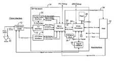
- FIG. 1is a block diagram of an oximeter incorporating the present invention.
- FIG. 2is a block diagram of a portion of the circuit of FIG. 1 illustrating the placement of a filter according to the present invention.
- FIG. 3is a circuit diagram of a band pass filter according to an embodiment of the invention.
- FIG. 4is a timing diagram illustrating the low and high pass filtering effects on the red and IR signals according to an embodiment of the invention.
- FIG. 5is a circuit diagram illustrating an embodiment of a LED drive circuit including the circuit connections for the calibration mode according to an embodiment of the invention.
- FIG. 1illustrates an embodiment of an oximetry system incorporating the present invention.
- a sensor 10includes red and infrared LEDs and a photodetector. These are connected by a cable 12 to a board 14 .
- LED drive currentis provided by an LED drive interface 16 .
- the received photocurrent from the sensoris provided to an I-V interface 18 .
- the IR and red voltagesare then provided to a sigma-delta interface 20 incorporating the present invention.
- the output of sigma-delta interface 20is provided to a microcontroller 22 .
- Microcontroller 22includes flash memory for a program, and SRAM memory for data.
- the processoralso includes a microprocessor chip 24 connected to a flash memory 26 .
- a clock 28is used and an interface 30 to a digital calibration in the sensor 10 is provided.
- a separate host 32receives the processed information, as well as receiving an analog signal on a line 34 for providing an analog display.
- FIG. 2is a block diagram illustrating the location of the filter according to an embodiment of the invention. Shown is a sensor 10 that is driven by an LED drive circuit 16 .
- the LED drive circuit 16alternately drives an IR LED 40 and a red LED 42 .
- a photodetector 44provides a signal to a current-to-voltage (I-V converter 46 ).
- the voltage signalis provided to high pass and anti-aliasing filter 48 .
- This blockincludes the band pass filter according to an embodiment of the invention.
- the output signalis then provided to a sigma-delta modulator 50 .
- the output of sigma-delta modulator 50is provided to a demodulator 52 , which is then provided to filtering and decimating blocks 54 and 56 .
- FIG. 3illustrates a band pass filter 60 according to an embodiment of the invention.
- the filterincludes an amplifier 62 and a resistor and capacitor circuit comprising capacitors C 2 , C 110 , C 111 , and C 40 and resistors R 7 , R 111 , R 112 , R 110 , and R 109 .
- An input to this circuitis provided from I-V converter 46 along a line 64 to a first switch 66 for an offset correction not relevant to the present invention.
- the signalis then provided to a second switch 68 , which is used for a calibration mode according to the present invention.
- a cross-talk control signal 70couples the switch to an LED current sense line 72 for calibration mode.
- the corner frequenciesare adjusted by varying the capacitor and resistor values to offset and minimize the cross-talk effect.
- the corner frequenciesare the high pass and low pass ends of the band pass filter, which is in place to filter out ambient interferences.
- the filter cornersAs close to the modulation frequency as possible. Raising the frequency of the high pass corner makes the filter better able to reject any AC portion of ambient light. Typically in the US, fluorescent lights have strong AC component at 120 Hz and the harmonics of 120 Hz. It is desirable to filter this out of the signal. Lowering the cut off frequency of the low pass filter limits the high frequency noise from the I-V converter, and provides some anti-aliasing to keep ambient noise out of the system.
- any filtering spreads out the signal in the time domainfor example some of the IR pulse will leak into the dark pulse following it.
- Tuning the band pass filter to optimize for cross-talkis done when it is designed by adjusting the high pass filter corner and the low pass corner to force the cross-talk to be zero.
- the size of the Red pulseis measured by comparing the sample P 5 (see FIG. 4 ) to the samples taken in the dark states P 4 and P 6 .
- the P 4 sampleSince the signal from the IR pulse is still decaying in the Dark 2 time period, the P 4 sample will be higher due to the low pass response and the lower due to the high pass response. The effect of the IR pulse on P 4 will affect the size of the measured red signal. This is a cause of cross-talk where the IR signal leaks into the Red signal and vice versa.
- the cornersare adjusted so that the high pass and low pass signals shown in FIG. 5 are adjusted so that the effect of the high pass filtering compensates for the effect of the low pass filtering to minimize cross-talk.
- the low pass filtercauses a positive cross-talk
- the high pass filtercauses an offsetting negative cross-talk.
- the band pass filterconsists of an RC high pass followed by a Salen-Key low pass configured as a second order Butterworth filter.
- the impedance of the RC high pass sectionwill have an effect on the transfer function of the Salen-Key circuit, however this effect is negligible if capacitance C 2 is much larger than C 110 and C 111 .
- the high pass filter cut off frequencyis 32 Hz.
- the low pass filter cut off frequencyis 12.7 kHz.
- FIG. 5is a circuit diagram of an embodiment of LED drive circuit 16 of FIG. 2 . Included in the circuit are a connection to the red LED on a line 80 , and a connection to the IR LED on a line 82 . These are provided through MOSFET transistors 84 and 86 to a 1 ohm resistor 88 . In the calibration mode, the LED current sense signal on line 72 is taken from the current through this 1 ohm resistor with line 72 of FIG. 5 connected to line 72 of FIG. 3 as an input through switch 68 to the band pass filter.
- connection of line 72 in FIG. 5 during a calibration modeallows a further correction for cross-talk using a cross-talk calibration test.
- a 50% drive signalis applied to the LEDs during the calibration circuit to give a sufficiently large signal without going to full range and risking too high of a signal being provided. Alternately, other percentages of the drive current could be used.
- the red cross-talk effectis determined by multiplying the percentage cross-talk times the red signal, and then it is subtracted from the IR signal. The corresponding action is done for the red signal.
- the present inventioncould be embodied in other specific forms without departing from the essential characteristic thereof.
- the drive currentcould be obtained in a different manner and a different design could be used for the band pass filter.
- the band pass filtercould be used alone, without the software calibration added. Accordingly, the foregoing description is intended to be illustrative, but not limiting, on the scope of the invention which is set forth in the following claims.
Landscapes
- Health & Medical Sciences (AREA)
- Life Sciences & Earth Sciences (AREA)
- Engineering & Computer Science (AREA)
- Physics & Mathematics (AREA)
- Surgery (AREA)
- Animal Behavior & Ethology (AREA)
- Pathology (AREA)
- Signal Processing (AREA)
- Biomedical Technology (AREA)
- Heart & Thoracic Surgery (AREA)
- Medical Informatics (AREA)
- Molecular Biology (AREA)
- Veterinary Medicine (AREA)
- Biophysics (AREA)
- General Health & Medical Sciences (AREA)
- Public Health (AREA)
- Artificial Intelligence (AREA)
- Computer Vision & Pattern Recognition (AREA)
- Physiology (AREA)
- Psychiatry (AREA)
- Spectroscopy & Molecular Physics (AREA)
- Optics & Photonics (AREA)
- Measurement Of The Respiration, Hearing Ability, Form, And Blood Characteristics Of Living Organisms (AREA)
- Investigating Or Analysing Materials By Optical Means (AREA)
Abstract
Description
Red′=Red−IR*Kcross
IR′=IR−Red*Kcross
Claims (19)
Priority Applications (8)
| Application Number | Priority Date | Filing Date | Title |
|---|---|---|---|
| US10/787,541US7215985B2 (en) | 2004-02-25 | 2004-02-25 | Oximeter cross-talk reduction |
| JP2007500780AJP4701235B2 (en) | 2004-02-25 | 2005-02-24 | Oxygen concentration meter crosstalk reduction |
| MXPA06009756AMXPA06009756A (en) | 2004-02-25 | 2005-02-24 | Oximeter cross-talk reduction. |
| AU2005216981AAU2005216981A1 (en) | 2004-02-25 | 2005-02-24 | Oximeter cross-talk reduction |
| PCT/US2005/006316WO2005082241A1 (en) | 2004-02-25 | 2005-02-24 | Oximeter cross-talk reduction |
| EP05731575AEP1722677A1 (en) | 2004-02-25 | 2005-02-24 | Oximeter cross-talk reduction |
| CA002556744ACA2556744A1 (en) | 2004-02-25 | 2005-02-24 | Oximeter cross-talk reduction |
| CNA2005800058586ACN1937952A (en) | 2004-02-25 | 2005-02-24 | Oximeter cross-talk reduction |
Applications Claiming Priority (1)
| Application Number | Priority Date | Filing Date | Title |
|---|---|---|---|
| US10/787,541US7215985B2 (en) | 2004-02-25 | 2004-02-25 | Oximeter cross-talk reduction |
Publications (2)
| Publication Number | Publication Date |
|---|---|
| US20050187452A1 US20050187452A1 (en) | 2005-08-25 |
| US7215985B2true US7215985B2 (en) | 2007-05-08 |
Family
ID=34861915
Family Applications (1)
| Application Number | Title | Priority Date | Filing Date |
|---|---|---|---|
| US10/787,541Expired - LifetimeUS7215985B2 (en) | 2004-02-25 | 2004-02-25 | Oximeter cross-talk reduction |
Country Status (8)
| Country | Link |
|---|---|
| US (1) | US7215985B2 (en) |
| EP (1) | EP1722677A1 (en) |
| JP (1) | JP4701235B2 (en) |
| CN (1) | CN1937952A (en) |
| AU (1) | AU2005216981A1 (en) |
| CA (1) | CA2556744A1 (en) |
| MX (1) | MXPA06009756A (en) |
| WO (1) | WO2005082241A1 (en) |
Cited By (11)
| Publication number | Priority date | Publication date | Assignee | Title |
|---|---|---|---|---|
| US20100087714A1 (en)* | 2008-10-03 | 2010-04-08 | Nellcor Puritan Bennett Ireland | Reducing cross-talk in a measurement system |
| US20100145645A1 (en)* | 2008-12-09 | 2010-06-10 | Oleg Gonopolskiy | System and method of determining light source aging |
| US20110004069A1 (en)* | 2009-07-06 | 2011-01-06 | Nellcor Puritan Bennett Ireland | Systems And Methods For Processing Physiological Signals In Wavelet Space |
| US20110028814A1 (en)* | 2008-03-31 | 2011-02-03 | Nellcor Puritan Bennett Llc | Medical Monitoring Patch Device And Methods |
| US20110077531A1 (en)* | 2009-09-29 | 2011-03-31 | Nellcor Puritan Bennett Ireland | Systems and methods for high-pass filtering a photoplethysmograph signal |
| US8265724B2 (en) | 2007-03-09 | 2012-09-11 | Nellcor Puritan Bennett Llc | Cancellation of light shunting |
| US8366613B2 (en) | 2007-12-26 | 2013-02-05 | Covidien Lp | LED drive circuit for pulse oximetry and method for using same |
| US8494786B2 (en) | 2009-07-30 | 2013-07-23 | Covidien Lp | Exponential sampling of red and infrared signals |
| US11143750B2 (en)* | 2015-10-22 | 2021-10-12 | Ams Sensors Singapore Pte. Ltd. | Optical crosstalk calibration for ranging systems |
| US11426103B2 (en) | 2008-07-03 | 2022-08-30 | Masimo Corporation | Multi-stream data collection system for noninvasive measurement of blood constituents |
| US11638532B2 (en) | 2008-07-03 | 2023-05-02 | Masimo Corporation | User-worn device for noninvasively measuring a physiological parameter of a user |
Families Citing this family (17)
| Publication number | Priority date | Publication date | Assignee | Title |
|---|---|---|---|---|
| US7647083B2 (en) | 2005-03-01 | 2010-01-12 | Masimo Laboratories, Inc. | Multiple wavelength sensor equalization |
| US7400310B2 (en)* | 2005-11-28 | 2008-07-15 | Draeger Medical Systems, Inc. | Pulse signal drive circuit |
| US8265723B1 (en) | 2006-10-12 | 2012-09-11 | Cercacor Laboratories, Inc. | Oximeter probe off indicator defining probe off space |
| US20080221418A1 (en)* | 2007-03-09 | 2008-09-11 | Masimo Corporation | Noninvasive multi-parameter patient monitor |
| EP2139383B1 (en) | 2007-03-27 | 2013-02-13 | Masimo Laboratories, Inc. | Multiple wavelength optical sensor |
| US8374665B2 (en) | 2007-04-21 | 2013-02-12 | Cercacor Laboratories, Inc. | Tissue profile wellness monitor |
| US8204567B2 (en)* | 2007-12-13 | 2012-06-19 | Nellcor Puritan Bennett Llc | Signal demodulation |
| US8380272B2 (en)* | 2007-12-21 | 2013-02-19 | Covidien Lp | Physiological sensor |
| US20090247846A1 (en)* | 2008-04-01 | 2009-10-01 | General Electric Company | Pulse oximeter with reduced cross talk effects |
| US9839381B1 (en) | 2009-11-24 | 2017-12-12 | Cercacor Laboratories, Inc. | Physiological measurement system with automatic wavelength adjustment |
| WO2011069122A1 (en) | 2009-12-04 | 2011-06-09 | Masimo Corporation | Calibration for multi-stage physiological monitors |
| US20120229800A1 (en)* | 2011-03-08 | 2012-09-13 | Fluke Corporation | Pulse oximeter test instruments and methods |
| US10541652B2 (en) | 2015-06-27 | 2020-01-21 | Intel Corporation | Apparatus and method for filter settling calibration to improve speed of tracking and cancelling of DC offset |
| US10568530B2 (en) | 2015-06-27 | 2020-02-25 | Intel Corporation | Apparatus and method for tracking and cancelling DC offset to acquire small AC signal |
| US10231632B2 (en)* | 2016-02-22 | 2019-03-19 | Intel Corporation | Apparatus and method for tracking and cancelling DC offset to acquire small AC signal using dual feedback loops |
| EP3406194B1 (en)* | 2017-05-23 | 2021-02-24 | ams AG | Circuit arrangement for an optical monitoring system and method for optical monitoring |
| CN109157207A (en)* | 2018-08-23 | 2019-01-08 | 深圳北芯生命科技有限公司 | Cross-interference elimination device and method based on FFR measurement |
Citations (14)
| Publication number | Priority date | Publication date | Assignee | Title |
|---|---|---|---|---|
| US4802486A (en) | 1985-04-01 | 1989-02-07 | Nellcor Incorporated | Method and apparatus for detecting optical pulses |
| US4911167A (en) | 1985-06-07 | 1990-03-27 | Nellcor Incorporated | Method and apparatus for detecting optical pulses |
| US4928692A (en) | 1985-04-01 | 1990-05-29 | Goodman David E | Method and apparatus for detecting optical pulses |
| US4934372A (en) | 1985-04-01 | 1990-06-19 | Nellcor Incorporated | Method and apparatus for detecting optical pulses |
| US4942877A (en) | 1986-09-05 | 1990-07-24 | Minolta Camera Kabushiki Kaisha | Device for measuring oxygen saturation degree in arterial blood |
| US5351685A (en) | 1991-08-05 | 1994-10-04 | Nellcor Incorporated | Condensed oximeter system with noise reduction software |
| US5368026A (en) | 1993-03-26 | 1994-11-29 | Nellcor Incorporated | Oximeter with motion detection for alarm modification |
| US5713355A (en) | 1992-10-23 | 1998-02-03 | Nellcor Puritan Bennett Incorporated | Method and apparatus for reducing ambient noise effects in electronic monitoring instruments |
| US5746697A (en) | 1996-02-09 | 1998-05-05 | Nellcor Puritan Bennett Incorporated | Medical diagnostic apparatus with sleep mode |
| US5921921A (en) | 1996-12-18 | 1999-07-13 | Nellcor Puritan-Bennett | Pulse oximeter with sigma-delta converter |
| US5995858A (en) | 1997-11-07 | 1999-11-30 | Datascope Investment Corp. | Pulse oximeter |
| US6226539B1 (en) | 1999-05-26 | 2001-05-01 | Mallinckrodt, Inc. | Pulse oximeter having a low power led drive |
| US20010002206A1 (en) | 1997-04-14 | 2001-05-31 | Diab Mohamed K. | Method and apparatus for demodulating signals in a pulse oximetry system |
| US6505133B1 (en) | 2000-11-15 | 2003-01-07 | Datex-Ohmeda, Inc. | Simultaneous signal attenuation measurements utilizing code division multiplexing |
Family Cites Families (2)
| Publication number | Priority date | Publication date | Assignee | Title |
|---|---|---|---|---|
| JP3521662B2 (en)* | 1996-12-04 | 2004-04-19 | 松下電器産業株式会社 | Blood glucose meter |
| JPH11216133A (en)* | 1998-02-04 | 1999-08-10 | Nippon Koden Corp | Apparatus and method for body motion noise removal pulse oximetry |
- 2004
- 2004-02-25USUS10/787,541patent/US7215985B2/ennot_activeExpired - Lifetime
- 2005
- 2005-02-24CNCNA2005800058586Apatent/CN1937952A/enactivePending
- 2005-02-24WOPCT/US2005/006316patent/WO2005082241A1/enactiveApplication Filing
- 2005-02-24EPEP05731575Apatent/EP1722677A1/ennot_activeWithdrawn
- 2005-02-24JPJP2007500780Apatent/JP4701235B2/ennot_activeExpired - Fee Related
- 2005-02-24MXMXPA06009756Apatent/MXPA06009756A/ennot_activeApplication Discontinuation
- 2005-02-24CACA002556744Apatent/CA2556744A1/ennot_activeAbandoned
- 2005-02-24AUAU2005216981Apatent/AU2005216981A1/ennot_activeAbandoned
Patent Citations (18)
| Publication number | Priority date | Publication date | Assignee | Title |
|---|---|---|---|---|
| US4802486A (en) | 1985-04-01 | 1989-02-07 | Nellcor Incorporated | Method and apparatus for detecting optical pulses |
| US4928692A (en) | 1985-04-01 | 1990-05-29 | Goodman David E | Method and apparatus for detecting optical pulses |
| US4934372A (en) | 1985-04-01 | 1990-06-19 | Nellcor Incorporated | Method and apparatus for detecting optical pulses |
| US4911167A (en) | 1985-06-07 | 1990-03-27 | Nellcor Incorporated | Method and apparatus for detecting optical pulses |
| US4942877A (en) | 1986-09-05 | 1990-07-24 | Minolta Camera Kabushiki Kaisha | Device for measuring oxygen saturation degree in arterial blood |
| US5351685A (en) | 1991-08-05 | 1994-10-04 | Nellcor Incorporated | Condensed oximeter system with noise reduction software |
| US5803910A (en) | 1991-08-05 | 1998-09-08 | Nellcor Puritan Bennett Incorporated | Condensed oximeter system and method with noise reduction software |
| US5713355A (en) | 1992-10-23 | 1998-02-03 | Nellcor Puritan Bennett Incorporated | Method and apparatus for reducing ambient noise effects in electronic monitoring instruments |
| US5662106A (en) | 1993-03-26 | 1997-09-02 | Nellcor Incorporated | Oximeter with motion detection for alarm modification |
| US5368026A (en) | 1993-03-26 | 1994-11-29 | Nellcor Incorporated | Oximeter with motion detection for alarm modification |
| US5746697A (en) | 1996-02-09 | 1998-05-05 | Nellcor Puritan Bennett Incorporated | Medical diagnostic apparatus with sleep mode |
| US5924979A (en) | 1996-02-09 | 1999-07-20 | Nellcor Puritan Bennett Incorporated | Medical diagnostic apparatus with sleep mode |
| US5921921A (en) | 1996-12-18 | 1999-07-13 | Nellcor Puritan-Bennett | Pulse oximeter with sigma-delta converter |
| US20010002206A1 (en) | 1997-04-14 | 2001-05-31 | Diab Mohamed K. | Method and apparatus for demodulating signals in a pulse oximetry system |
| US5995858A (en) | 1997-11-07 | 1999-11-30 | Datascope Investment Corp. | Pulse oximeter |
| US6226539B1 (en) | 1999-05-26 | 2001-05-01 | Mallinckrodt, Inc. | Pulse oximeter having a low power led drive |
| US6505133B1 (en) | 2000-11-15 | 2003-01-07 | Datex-Ohmeda, Inc. | Simultaneous signal attenuation measurements utilizing code division multiplexing |
| US20030028357A1 (en)* | 2000-11-15 | 2003-02-06 | Norris Mark A. | Reduced cross talk pulse oximeter |
Cited By (27)
| Publication number | Priority date | Publication date | Assignee | Title |
|---|---|---|---|---|
| US9642576B2 (en) | 2007-03-09 | 2017-05-09 | Covidien Lp | Cancellation of light shunting |
| US8923944B2 (en) | 2007-03-09 | 2014-12-30 | Covidien Lp | Cancellation of light shunting |
| US8265724B2 (en) | 2007-03-09 | 2012-09-11 | Nellcor Puritan Bennett Llc | Cancellation of light shunting |
| US8366613B2 (en) | 2007-12-26 | 2013-02-05 | Covidien Lp | LED drive circuit for pulse oximetry and method for using same |
| US20110028814A1 (en)* | 2008-03-31 | 2011-02-03 | Nellcor Puritan Bennett Llc | Medical Monitoring Patch Device And Methods |
| US8750954B2 (en) | 2008-03-31 | 2014-06-10 | Covidien Lp | Medical monitoring patch device and methods |
| US11484229B2 (en) | 2008-07-03 | 2022-11-01 | Masimo Corporation | User-worn device for noninvasively measuring a physiological parameter of a user |
| US11642037B2 (en) | 2008-07-03 | 2023-05-09 | Masimo Corporation | User-worn device for noninvasively measuring a physiological parameter of a user |
| US12036009B1 (en) | 2008-07-03 | 2024-07-16 | Masimo Corporation | User-worn device for noninvasively measuring a physiological parameter of a user |
| US12023139B1 (en) | 2008-07-03 | 2024-07-02 | Masimo Corporation | User-worn device for noninvasively measuring a physiological parameter of a user |
| US11751773B2 (en) | 2008-07-03 | 2023-09-12 | Masimo Corporation | Emitter arrangement for physiological measurements |
| US11647914B2 (en) | 2008-07-03 | 2023-05-16 | Masimo Corporation | User-worn device for noninvasively measuring a physiological parameter of a user |
| US11642036B2 (en) | 2008-07-03 | 2023-05-09 | Masimo Corporation | User-worn device for noninvasively measuring a physiological parameter of a user |
| US11638532B2 (en) | 2008-07-03 | 2023-05-02 | Masimo Corporation | User-worn device for noninvasively measuring a physiological parameter of a user |
| US11484230B2 (en) | 2008-07-03 | 2022-11-01 | Masimo Corporation | User-worn device for noninvasively measuring a physiological parameter of a user |
| US11426103B2 (en) | 2008-07-03 | 2022-08-30 | Masimo Corporation | Multi-stream data collection system for noninvasive measurement of blood constituents |
| US20100087714A1 (en)* | 2008-10-03 | 2010-04-08 | Nellcor Puritan Bennett Ireland | Reducing cross-talk in a measurement system |
| US20100145645A1 (en)* | 2008-12-09 | 2010-06-10 | Oleg Gonopolskiy | System and method of determining light source aging |
| US9404961B2 (en) | 2008-12-09 | 2016-08-02 | Covidien Lp | System and method of determining light source aging |
| US20110004069A1 (en)* | 2009-07-06 | 2011-01-06 | Nellcor Puritan Bennett Ireland | Systems And Methods For Processing Physiological Signals In Wavelet Space |
| US8636667B2 (en) | 2009-07-06 | 2014-01-28 | Nellcor Puritan Bennett Ireland | Systems and methods for processing physiological signals in wavelet space |
| US9380969B2 (en) | 2009-07-30 | 2016-07-05 | Covidien Lp | Systems and methods for varying a sampling rate of a signal |
| US8494786B2 (en) | 2009-07-30 | 2013-07-23 | Covidien Lp | Exponential sampling of red and infrared signals |
| US9649071B2 (en) | 2009-09-29 | 2017-05-16 | Nellcor Puritan Bennett Ireland | Systems and methods for high-pass filtering a photoplethysmograph signal |
| US9066660B2 (en) | 2009-09-29 | 2015-06-30 | Nellcor Puritan Bennett Ireland | Systems and methods for high-pass filtering a photoplethysmograph signal |
| US20110077531A1 (en)* | 2009-09-29 | 2011-03-31 | Nellcor Puritan Bennett Ireland | Systems and methods for high-pass filtering a photoplethysmograph signal |
| US11143750B2 (en)* | 2015-10-22 | 2021-10-12 | Ams Sensors Singapore Pte. Ltd. | Optical crosstalk calibration for ranging systems |
Also Published As
| Publication number | Publication date |
|---|---|
| JP4701235B2 (en) | 2011-06-15 |
| JP2007523715A (en) | 2007-08-23 |
| WO2005082241A1 (en) | 2005-09-09 |
| EP1722677A1 (en) | 2006-11-22 |
| MXPA06009756A (en) | 2007-03-30 |
| AU2005216981A1 (en) | 2005-09-09 |
| US20050187452A1 (en) | 2005-08-25 |
| CN1937952A (en) | 2007-03-28 |
| CA2556744A1 (en) | 2005-09-09 |
Similar Documents
| Publication | Publication Date | Title |
|---|---|---|
| US7215985B2 (en) | Oximeter cross-talk reduction | |
| CA2556748C (en) | Oximeter ambient light cancellation | |
| US6963767B2 (en) | Pulse oximeter | |
| US9380969B2 (en) | Systems and methods for varying a sampling rate of a signal | |
| US8386000B2 (en) | System and method for photon density wave pulse oximetry and pulse hemometry | |
| EP1250885A2 (en) | Oxygen-saturation measuring apparatus | |
| CN201033073Y (en) | Sphygmus blood oxygen test apparatus | |
| EP0261788A1 (en) | Multiple-pulse method and apparatus for use in oximetry | |
| US20120310060A1 (en) | Method of analyzing photon density waves in a medical monitor | |
| KR970006916B1 (en) | Oxygen measuring device for measuring blood component of artery and its method | |
| US20140275878A1 (en) | Methods and systems for equalizing physiological signals | |
| KR20070020428A (en) | Cross-talk reduction of oximeter |
Legal Events
| Date | Code | Title | Description |
|---|---|---|---|
| AS | Assignment | Owner name:NELLCOR PURITAN BENNETT INC., CALIFORNIA Free format text:ASSIGNMENT OF ASSIGNORS INTEREST;ASSIGNORS:PETERSEN, ETHAN;CHEW, BRADFORD B.;SHEA, WILLIAM;REEL/FRAME:014564/0022 Effective date:20040422 | |
| STCF | Information on status: patent grant | Free format text:PATENTED CASE | |
| FPAY | Fee payment | Year of fee payment:4 | |
| AS | Assignment | Owner name:NELLCOR PURITAN BENNETT LLC, COLORADO Free format text:CHANGE OF NAME;ASSIGNOR:NELLCOR PURITAN BENNETT INCORPORATED;REEL/FRAME:029247/0329 Effective date:20061220 | |
| AS | Assignment | Owner name:COVIDIEN LP, MASSACHUSETTS Free format text:ASSIGNMENT OF ASSIGNORS INTEREST;ASSIGNOR:NELLCOR PURITAN BENNETT LLC;REEL/FRAME:029330/0561 Effective date:20120929 | |
| FPAY | Fee payment | Year of fee payment:8 | |
| MAFP | Maintenance fee payment | Free format text:PAYMENT OF MAINTENANCE FEE, 12TH YEAR, LARGE ENTITY (ORIGINAL EVENT CODE: M1553); ENTITY STATUS OF PATENT OWNER: LARGE ENTITY Year of fee payment:12 |