US7215495B1 - System and method for determining head-disk contact in a magnetic recording disk drive - Google Patents
System and method for determining head-disk contact in a magnetic recording disk driveDownload PDFInfo
- Publication number
- US7215495B1 US7215495B1US11/320,423US32042305AUS7215495B1US 7215495 B1US7215495 B1US 7215495B1US 32042305 AUS32042305 AUS 32042305AUS 7215495 B1US7215495 B1US 7215495B1
- Authority
- US
- United States
- Prior art keywords
- disk
- head
- slider
- actuator
- read
- Prior art date
- Legal status (The legal status is an assumption and is not a legal conclusion. Google has not performed a legal analysis and makes no representation as to the accuracy of the status listed.)
- Expired - Fee Related
Links
- 238000000034methodMethods0.000titleclaimsabstractdescription36
- 230000011664signalingEffects0.000claimsdescription7
- 230000002401inhibitory effectEffects0.000claimsdescription4
- 230000003213activating effectEffects0.000claims3
- 239000000725suspensionSubstances0.000abstractdescription21
- 230000010354integrationEffects0.000abstractdescription6
- 230000009471actionEffects0.000abstractdescription4
- 230000000712assemblyEffects0.000abstractdescription4
- 238000000429assemblyMethods0.000abstractdescription4
- 238000012360testing methodMethods0.000abstractdescription4
- 230000010355oscillationEffects0.000description11
- 230000003595spectral effectEffects0.000description6
- 238000001228spectrumMethods0.000description5
- 230000001965increasing effectEffects0.000description4
- 238000010586diagramMethods0.000description3
- 230000001939inductive effectEffects0.000description3
- 230000001276controlling effectEffects0.000description2
- 230000000875corresponding effectEffects0.000description2
- 230000006870functionEffects0.000description2
- 230000008859changeEffects0.000description1
- 238000006243chemical reactionMethods0.000description1
- 230000002596correlated effectEffects0.000description1
- 238000007405data analysisMethods0.000description1
- 238000001514detection methodMethods0.000description1
- 230000000694effectsEffects0.000description1
- 238000005516engineering processMethods0.000description1
- 239000011521glassSubstances0.000description1
- 238000010438heat treatmentMethods0.000description1
- 238000004519manufacturing processMethods0.000description1
- 230000005055memory storageEffects0.000description1
- 239000002184metalSubstances0.000description1
- 230000004044responseEffects0.000description1
- 238000000926separation methodMethods0.000description1
- 230000035939shockEffects0.000description1
- 239000000758substrateSubstances0.000description1
Images


Classifications
- G—PHYSICS
- G11—INFORMATION STORAGE
- G11B—INFORMATION STORAGE BASED ON RELATIVE MOVEMENT BETWEEN RECORD CARRIER AND TRANSDUCER
- G11B5/00—Recording by magnetisation or demagnetisation of a record carrier; Reproducing by magnetic means; Record carriers therefor
- G11B5/455—Arrangements for functional testing of heads; Measuring arrangements for heads
- G—PHYSICS
- G11—INFORMATION STORAGE
- G11B—INFORMATION STORAGE BASED ON RELATIVE MOVEMENT BETWEEN RECORD CARRIER AND TRANSDUCER
- G11B19/00—Driving, starting, stopping record carriers not specifically of filamentary or web form, or of supports therefor; Control thereof; Control of operating function ; Driving both disc and head
- G11B19/02—Control of operating function, e.g. switching from recording to reproducing
- G11B19/04—Arrangements for preventing, inhibiting, or warning against double recording on the same blank or against other recording or reproducing malfunctions
- G—PHYSICS
- G11—INFORMATION STORAGE
- G11B—INFORMATION STORAGE BASED ON RELATIVE MOVEMENT BETWEEN RECORD CARRIER AND TRANSDUCER
- G11B27/00—Editing; Indexing; Addressing; Timing or synchronising; Monitoring; Measuring tape travel
- G11B27/36—Monitoring, i.e. supervising the progress of recording or reproducing
- G—PHYSICS
- G11—INFORMATION STORAGE
- G11B—INFORMATION STORAGE BASED ON RELATIVE MOVEMENT BETWEEN RECORD CARRIER AND TRANSDUCER
- G11B5/00—Recording by magnetisation or demagnetisation of a record carrier; Reproducing by magnetic means; Record carriers therefor
- G11B5/48—Disposition or mounting of heads or head supports relative to record carriers ; arrangements of heads, e.g. for scanning the record carrier to increase the relative speed
- G11B5/58—Disposition or mounting of heads or head supports relative to record carriers ; arrangements of heads, e.g. for scanning the record carrier to increase the relative speed with provision for moving the head for the purpose of maintaining alignment of the head relative to the record carrier during transducing operation, e.g. to compensate for surface irregularities of the latter or for track following
- G11B5/60—Fluid-dynamic spacing of heads from record-carriers
- G11B5/6005—Specially adapted for spacing from a rotating disc using a fluid cushion
- G11B5/6011—Control of flying height
- G11B5/6064—Control of flying height using air pressure
- G—PHYSICS
- G11—INFORMATION STORAGE
- G11B—INFORMATION STORAGE BASED ON RELATIVE MOVEMENT BETWEEN RECORD CARRIER AND TRANSDUCER
- G11B2220/00—Record carriers by type
- G11B2220/20—Disc-shaped record carriers
- G11B2220/25—Disc-shaped record carriers characterised in that the disc is based on a specific recording technology
- G11B2220/2508—Magnetic discs
- G11B2220/2516—Hard disks
Definitions
- Concurrently-filed application Ser. No. 11/320,425relates to a SYSTEM AND METHOD FOR CALIBRATING AND CONTROLLING A FLY-HEIGHT ACTUATOR IN A MAGNETIC RECORDING DISK DRIVE.
- This inventionrelates to magnetic recording disk drives, and more particularly to a system and method for determining contact of the read/write head or the head carrier with the disk.
- Magnetic recording hard disk drivesuse a read/write transducer or head mounted on a head carrier for reading and/or writing data to the disk.
- the head carrieris typically an air-bearing slider attached to an actuator arm by a suspension and positioned very close to the disk surface by the suspension.
- the separation between the head and the disk surfaceis called the fly height.
- the sliderhas a disk-facing air-bearing surface (ABS) that causes the slider to ride on a cushion or bearing of air generated by rotation of the disk.
- ABSdisk-facing air-bearing surface
- the slideris attached to a flexure on the suspension and the suspension includes a load beam that applies a load force to the slider to counteract the air-bearing force while permitting the slider to “pitch” and “roll”.
- the flying dynamics of the slider and thus the fly heightare influenced by factors such as the rotation speed of the disk, the aerodynamic shape of the slider's ABS, the load force applied to the slider by the suspension, and the pitch and roll torques applied to the slider by the suspension.
- Disk drivesare susceptible to failure of the slider-disk interface which can result in a head “crash” during operation. This may result in loss of data or complete failure of the disk drive.
- head-disk contactcollectively called head-disk contact (HDC)
- Disk driveshave been proposed that use a fly-height actuator for changing the spacing between the head and the disk surface.
- One type of fly-height actuatoris a thermal actuator with an electrically-resistive heater located on the slider near the head. When current is applied to the heater the heater expands and moves the head closer to the disk surface.
- Other fly-height actuators for moving the head relative to the sliderinclude electrostatic microactuators and piezoelectric actuators.
- Another type of fly-height actuatoralso based on thermal, electrostatic or piezoelectric techniques, changes the head-disk spacing by altering the air-flow or the shape of the slider's ABS. In disk drives that have a fly-height actuator it is also important to be able to determine the onset of HDC so that the fly-height actuator can be accurately controlled.
- a method for determining HDCis also important during the design and testing of disk drive components, in particular the slider ABS and the fly-height actuator.
- the inventionis system and method for determining HDC in a disk drive using the signal from the magnetoresistive (MR) read head.
- the signalis measured over a low-frequency range, with the slider out-of-contact with the disk, to develop a reference value.
- the signalis then measured over the same low-frequency range and this measured value is compared to the reference value.
- the analog MR signalis digitized and input to a digital signal processor with circuitry and/or software for integrating the signal amplitude over a low-frequency range, preferably between about 0.1 and 2 MHz.
- the calculated value from the integration when the slider is out-of-contact with the diskis the reference value.
- the same integrationis then performed during operation of the disk drive, when the spacing between the head and disk can vary, and the measured value is compared to the reference value. If the measured value exceeds the reference value by some predetermined amount, this is an indication of the onset of HDC or that HDC has occurred.
- the methodhas application in head-disk testers or “spin stands” to facilitate the design and testing of slider-suspension assemblies and fly-height actuators, as well as in disk drives to take corrective action before HDC and/or to control fly-height actuators.
- the inventionis also a magnetic recording disk drive that has a fly-height actuator and a digital signal processor with circuitry and/or software that performs the above-described integration and comparison.
- the processordetermines the onset of HDC or that HDC has occurred, it generates a control signal that can be used to cause the fly-height actuator to increase the head-disk spacing or to take corrective action, such as inhibiting the writing of data.
- FIG. 1is a schematic block diagram of a magnetic recording disk drive.
- FIG. 2is a sectional view of the end portion of air-bearing slider above the surface of a disk and illustrates a thermal fly-height actuator, a read head and a write head on the slider.
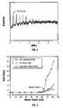
- FIGS. 3A–3Cshow the read signal amplitude as a function of frequency for three increasing levels of power applied to the thermal fly-height actuator.
- FIG. 4is a Fourier transform of the head-disk contact (HDC) oscillation signal at low frequency for a specified power applied to the thermal fly-height actuator.
- HDChead-disk contact
- FIG. 5shows three parameters (integrated equivalent noise ratio due to HDC, output amplitude ratio of a conventional acoustic-emission sensor, and the acoustic-emission standard deviation ratio) vs. heater power for a particular slider-suspension assembly.
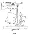
- FIG. 6is a schematic block diagram a magnetic recording disk drive that incorporates the method for determining HDC according to this invention.
- the inventionis applicable not only to magnetic recording disk drives, but also to head-disk testers or “spin stands” that are used in disk drive manufacturing to design and test the head-disk interface in magnetic recording disk drives.
- the inventionis applicable to conventional disk drives that do not have active control of the head-disk spacing, as well as to disk drives with head fly-height actuators that move the read-write head relative to the slider or alter the air-flow or shape of the slider's air-bearing surface (ABS) to control the head-disk spacing.
- ABSair-bearing surface
- FIG. 1is a schematic block diagram of a magnetic recording disk drive.
- the disk driveincludes a magnetic recording disk 10 with surfaces 11 and 12 , each of which contains a magnetic recording layer.
- the disk 10is mounted on a spindle 6 and rotated by a spindle motor 8 about an axis perpendicular to the disk surfaces 11 , 12 .
- a head carrier or slider 13is positioned near the surface 11 of disk 10 .
- Slider 13is an air-bearing slider having an air-bearing surface (ABS) 20 facing toward the disk surface 11 and a trailing end 22 .
- Slider 13supports a read/write transducer or head 21 on its trailing end 22 for reading and writing data to the magnetic media on disk surface 11 .
- ABSair-bearing surface
- the head 21is a dual-element head having an inductive write element or head 70 and an MR read element or head 60 .
- Slider 13is attached to an actuator arm 14 by means of a suspension 15 .
- the suspension 15provides a spring force that biases the slider 13 toward the disk surface 11 .
- a second head carrier or slider 17also supporting a read/write head, is positioned on surface 12 of disk 10 and is attached to actuator arm 14 by means of suspension 19 .
- Actuator arm 14is attached to a rotary actuator 27 .
- the actuatoris typically a rotary voice coil motor (VCM) that comprises a coil movable within a fixed magnetic field, the direction and velocity of the coil movements being controlled by motor current signals supplied by a hard-disk controller 29 .
- VCMrotary voice coil motor
- the rotary actuator 27moves the sliders 13 , 17 in a generally arcuate path radially in and out over their respective disk surfaces 11 , 12 so that the read/write heads may access different portions of the magnetic recording layers where data is desired to be read or recorded.
- Both the actuator 27 and spindle motor 8are mounted to a portion of the disk drive housing 9 .
- FIG. 2is a sectional view of the end portion of slider 13 above the surface 11 of disk 10 .
- the rotation of the disk 10 in the direction of arrow 100generates an air bearing between the ABS of slider 13 and disk surface 11 .
- the air bearingcounterbalances the slight spring force of the suspension and supports the slider 13 off and slightly away from the disk surface 11 by a small, substantially constant spacing.
- FIG. 2also shows the read/write head 21 , i.e., a magnetoresistive (MR) read head 60 and write head 70 .
- Write head 70is an inductive write head with coil 71 located between the two write poles 72 , 73 .
- the slider 13also includes a fly-height actuator for changing the spacing between read/write head 21 and the disk surface 11 .
- the type of fly-height actuator shown in FIG. 2is a thermal actuator with an electrically-resistive heating element or heater 80 electrically connected to and controlled by a fly-height controller (FHC) 82 .
- FHC 82is a power source that controls the amount of current to the heater 80 , such as by controlling the settings of a variable resistor. As the current increases, the heater 80 expands and moves the MR read head 60 and pole tips 71 , 72 of write head 70 closer to disk surface 11 , as shown by the dashed line 102 .
- the FHC 82may include a temperature feedback control circuit that monitors the temperature of the heater 80 to maintain the fly height of the head within a desired range during operation of the disk drive.
- a thermal fly-height actuatoris described in U.S. Pat. No. 5,991,113 and published patent application U.S. 2005/0024775 A1.
- Other fly-height actuators for moving the head relative to the sliderinclude electrostatic microactuators, such as described in U.S. Pat. No. 6,611,399 B1, and piezoelectric actuators, such as described in U.S. Pat. No. 6,570,730 B1.
- Another type of fly-height actuatorchanges the head-disk spacing by altering the air-flow or the shape of the slider's ABS.
- This type of fly-height actuatorincludes thermal actuators, such as described in U.S. Pat. No. 6,775,103 B2, electrostatic actuators, such as described in U.S. Pat. Nos. 5,276,573 and 6,344,949, and piezoelectric actuators, such as described in U.S. Pat. No. 5,021,906.
- Controller 29is a digital signal processor that includes logic control circuits, memory storage, and a microprocessor. Controller 29 generates control signals for the various drive operations, such as control signals on line 23 to spindle motor controller 30 , track following and track seek control signals on line 28 for actuator 27 , and control signals on line 83 to FHC 82 .
- Data from disk surface 11is read by the MR read head 60 .
- the MR signalis amplified by amplifier 37 .
- the amplifier 37 and other read signal processing circuitry, as well as the circuitry for generating the sense or bias current to the MR read head 60are typically part of an integrated circuit module 18 ( FIG. 1 ) located on actuator arm 14 .
- the module 18is placed close to the read/write head 21 to keep the interconnections as short as possible, and is thus called the arm electronics module.
- the output from MR amplifier 37is sent to the read/write (R/W) channel 25 where the analog signal from the MR read head 60 is processed into digital signals representing data recorded on the magnetic recording layer of disk surface 11 .
- R/W channel 25typically includes circuitry for automatic gain control, analog to digital conversion, and digital data detection.
- Datais written to the magnetic recording layer of disk surface 11 by write signals sent through R/W channel 25 and write amplifier 39 to inductive write head 70 .
- Write amplifier 39is typically located in arm electronics module 18 .
- the disk drivemay also include the ability to inhibit the writing of data upon the occurrence of some event, typically an external shock or an impending head crash. This is accomplished by a “write inhibit” signal from controller 29 on line 58 to the R/W channel 25 .
- the track following and seek control signals on line 28are generated by controller 29 that runs a servo control algorithm in response to input head position error signals (PES).
- the MR read head 60reads head position servo information recorded on the disk, typically at equally angularly spaced servo sectors embedded between the data sectors.
- This analog servo output from MR amplifier 37is demodulated by demodulator 38 and converted to a digital position error signal (PES) by analog-to-digital (A/D) converter 40 .
- the track following and seek control signals on line 28are sent to digital-to-analog converter (DAC) 32 that converts them to analog voltage signals which are output to VCM driver 34 .
- VCM driver 34then sends corresponding current pulses to the coil of VCM actuator 27 to pivot the arm 14 radially inward and outward to move and position the sliders 13 , 17 to the desired data tracks on the respective disk surfaces 11 , 12 .
- the inventionis a system and method for determining head-disk contact (HDC) in a disk drive using the MR signal.
- head-disk contactor HDC means that some portion of the slider, such as the read head 60 , the write head 70 , or the trailing end 22 , is in contact with the disk surface 11 .
- determiningmeans detecting the onset of HDC or concluding that HDC has occurred or is imminent.
- HDC oscillation signalA low-frequency oscillation of the MR signal has been observed at the onset of HDC and during HDC.
- This signalis called the HDC oscillation signal because it is caused entirely by the effect of HDC.
- the first harmonic frequency of HDC oscillationwas found to be very close to the slider pitch mode resonant frequency.
- the signalis not sensitive to many other factors, like radial position of the head on the disk, disk RPM and the type of disk (metal or glass substrate).
- the HDC oscillation signalis relatively easy to detect for different disk drives and different slider-suspension assemblies.
- FIGS. 3A–3Cshow the MR signal amplitude as a function of frequency for three different levels of heater power.
- no poweris applied to the heater and thus the head is not in contact with the disk, with the fly height being determined essentially by the air-bearing between the slider and the rotating disk.
- the applied heater poweris 94 mW and there is an onset of HDC, as shown by the signal amplitude below 1 MHz.
- the applied heater poweris 111 mW and HDC has occurred.
- FIG. 5shows three parameters (integrated equivalent noise ratio due to HDC, output amplitude ratio of a conventional acoustic-emission sensor, and the acoustic-emission standard deviation ratio) vs. heater power for a particular slider-suspension assembly.
- the integrated equivalent noise ratiois a ratio of integrated equivalent noise with heater power tested to that with zero power, i.e., the ratio of measured integrated spectral density to the integrated spectral density reference value.
- the frequency range of interestis from about 0.1 to 2 MHz, depending on the mechanical property of the HGA (the “head-gimbal-assembly”, a system including the suspension and slider with the read/write head).
- the frequency rangewas selected from 0.3 to 1.0 MHz to sufficiently cover the mechanical resonance vibration frequencies of the HGAs being tested.
- the output of the MR headis almost entirely noise so the integrated power spectrum can also be considered as integrated equivalent noise.
- the MR signalis normal low-frequency noise of the recording system and the integrated spectral density, i.e., the integration of the signal amplitude over the frequency range of interest, will be very low. This value can be used as a reference value.
- the measured value of integrated spectral densitywill increase and will continue to increase with increasing heater power.
- the heater poweris greater than the power at which the onset of HDC occurs, the measured value will increase dramatically with increasing heater power.
- the onset of HDCcan be determined and correlated with the corresponding heater power.
- the onset of HDCoccurs at a heater power of about 64 mW, which corresponds to an integrated equivalent noise ratio of approximately 1.9.
- an acoustic-emission (AE) sensorwas mounted on the arm supporting the slider-suspension assembly, and the AE sensor amplitude ratio and its standard deviation (StDev) ratio were measured and plotted in FIG. 5 .
- the AE amplitude ratio and StDev ratio in FIG. 5are the ratios of AE sensor amplitude and StDev with heater power tested to AE sensor amplitude and StDev, respectively, at zero heater power.
- the method of the inventionWhen the method of the invention is used in a head-disk tester it facilitates the design of disk drive components.
- the methodallows particular slider-suspension assemblies, slider designs and air-bearing shapes to be evaluated. With the assembly or slider to be studied placed in the spin stand, the disk rotational speed can be reduced until HDC is determined, in the manner described above, to evaluate the flying characteristics of the slider.
- the methodallows particular fly-height actuators to be evaluated by determining the value of the FHC signal, e.g., heater power for a thermal actuator, at which HDC occurs.
- the data shown in FIGS. 3–5was accumulated using a head-disk tester or spin stand, such as the Guzik Model V2002 XY-positioning spin stand from Guzik Technical Enterprises, with the MR signal being input to either an internal spectrum analyzer on the Guzik spin stand or an external commercially available spectrum analyzer or digital oscilloscope.
- Digital oscilloscopes and digital disk drive analyzerssuch as those available from LeCroy Corporation, digitize the MR signal by an analog-to-digital converter (ADC) to create a data set that is stored in the memory of a microprocessor. The data set is processed and sent to the display.
- ADCanalog-to-digital converter
- complex processing of the digital signalcan be performed by high-speed digital signal processing circuits.
- the oscilloscope or analyzerincludes programmable signal analysis software that can extract many useful time-domain features (e.g., rise time, pulse width, amplitude), frequency spectra, and other parameters, and is thus able to calculate the integrated spectral density of the MR signal.
- time-domain featurese.g., rise time, pulse width, amplitude
- frequency spectrae.g., frequency spectra, and other parameters
- the method of the inventioncan also be implemented in a disk drive.
- the MR signal from MR amplifier 37is also sent to an ADC 110 and then input to controller 29 .
- controller 29analyzes the digitized MR signal and runs the program to calculate the integrated reference value and the integrated measured value and generates a control signal when the integrated equivalent noise ratio exceeds a predetermined threshold, thus indicating or signaling the onset of HDC.
- the control signal on line 58would be a “write inhibit” signal sent to R/W channel 25 to prevent the write head 70 from writing data because of an impending head crash.
- the control signal on line 83would signal the FHC 82 to reduce heater power to move the head away from the disk.
Landscapes
- Adjustment Of The Magnetic Head Position Track Following On Tapes (AREA)
Abstract
Description
Claims (20)
Priority Applications (1)
| Application Number | Priority Date | Filing Date | Title |
|---|---|---|---|
| US11/320,423US7215495B1 (en) | 2005-12-27 | 2005-12-27 | System and method for determining head-disk contact in a magnetic recording disk drive |
Applications Claiming Priority (1)
| Application Number | Priority Date | Filing Date | Title |
|---|---|---|---|
| US11/320,423US7215495B1 (en) | 2005-12-27 | 2005-12-27 | System and method for determining head-disk contact in a magnetic recording disk drive |
Publications (1)
| Publication Number | Publication Date |
|---|---|
| US7215495B1true US7215495B1 (en) | 2007-05-08 |
Family
ID=38001040
Family Applications (1)
| Application Number | Title | Priority Date | Filing Date |
|---|---|---|---|
| US11/320,423Expired - Fee RelatedUS7215495B1 (en) | 2005-12-27 | 2005-12-27 | System and method for determining head-disk contact in a magnetic recording disk drive |
Country Status (1)
| Country | Link |
|---|---|
| US (1) | US7215495B1 (en) |
Cited By (34)
| Publication number | Priority date | Publication date | Assignee | Title |
|---|---|---|---|---|
| US20070127148A1 (en)* | 2005-12-01 | 2007-06-07 | Fujitsu Limited | Apparatus and method for detecting contact between head and recording medium, and method for manufacturing head |
| US20070217051A1 (en)* | 2006-03-14 | 2007-09-20 | Yong Shen | System and method for determining head-disk contact in a magnetic recording disk drive by magnetoresistive signal amplitude |
| US20070230018A1 (en)* | 2006-03-29 | 2007-10-04 | Seagate Technology | Actuation efficiency based contact detection |
| US20070230015A1 (en)* | 2006-03-28 | 2007-10-04 | Fujitsu Limited | Storage device, control method, control device, and program |
| US20070236821A1 (en)* | 2006-04-10 | 2007-10-11 | Iomega Corporation | Detecting head/disk contact in a disk drive using a calibration parameter |
| US20070247739A1 (en)* | 2006-04-21 | 2007-10-25 | Fujitsu Limited | Information recording/reproduction apparatus, head levitation height control method and head levitation control circuit |
| US20070268613A1 (en)* | 2006-05-18 | 2007-11-22 | Seagate Technology Llc | Regulating data writes responsive to head fly height |
| US20080239560A1 (en)* | 2007-03-27 | 2008-10-02 | Fujitsu Limited | Magnetic device and method of controlling magnetic device |
| US20080291564A1 (en)* | 2007-05-25 | 2008-11-27 | Samsung Electronics Co., Ltd. | Detecting head-disk contact during off-track operations |
| US20090141391A1 (en)* | 2007-11-30 | 2009-06-04 | Kenichi Kuramoto | Disk drive device and clearance control method thereof |
| US20090168221A1 (en)* | 2007-12-28 | 2009-07-02 | Peter Michael Baumgart | Method and system for detecting a change in a rotational velocity of a magnetic disk or a spindle coupled to the magnetic disk |
| US20090244752A1 (en)* | 2008-03-31 | 2009-10-01 | Baumgart Peter M | Head spacing verification in magnetic disk drive systems during end-user operation |
| US20090268330A1 (en)* | 2008-04-28 | 2009-10-29 | Samsung Electronics Co., Ltd. | Method and apparatus estimating touch-down approach flying height for magnetic head of disk drive |
| US20090290246A1 (en)* | 2008-05-21 | 2009-11-26 | Sae Magnetics (H.K.) Ltd. | Method for testing performance of a magnetic head slider |
| US7660068B1 (en) | 2008-09-18 | 2010-02-09 | Hitachi Global Storage Technologies Netherlands B.V. | Method and system for pre-contact detection and active damping of air bearing vibrations in a hard disk drive |
| US20100033860A1 (en)* | 2008-08-06 | 2010-02-11 | Tomita Craig L | Proximity Detection Method For Magnetic Head And Recording Medium |
| US20100142073A1 (en)* | 2008-12-05 | 2010-06-10 | Michael Alex | Method and apparatus for controlling fly-height of a perpendicular-magnetic-recording head in a hard disk drive |
| US20100157765A1 (en)* | 2008-12-19 | 2010-06-24 | Seagate Technology Llc | Collection of readback signal modulation data |
| US20100157454A1 (en)* | 2008-12-23 | 2010-06-24 | Chen Martin Yu-Wen | Head-disk contact detection and work function difference determination |
| US20100177429A1 (en)* | 2009-01-14 | 2010-07-15 | Seagate Technology Llc | Readback Signal-Based Head-Disc Contact Detection Using AM/FM Demodulation |
| US20110013305A1 (en)* | 2009-07-16 | 2011-01-20 | Ehrlich Richard M | Proximity detection method for magnetic head and recording medium |
| US20110141603A1 (en)* | 2009-12-10 | 2011-06-16 | Michiya Kazusawa | Head/disk contact determination |
| US7974039B1 (en) | 2009-06-17 | 2011-07-05 | Western Digital Technology, Inc. | Disk drive to reduce head instability |
| US20120218659A1 (en)* | 2011-02-28 | 2012-08-30 | Seagate Technology Llc | Contact detection |
| US8611036B2 (en)* | 2012-05-06 | 2013-12-17 | HGST Netherlands B.V. | Disk drive with head thermal fly-height actuator and controller for compensation of write head expansion |
| US8630055B2 (en) | 2011-02-22 | 2014-01-14 | Lsi Corporation | Systems and methods for medium contact detection |
| US8755136B1 (en) | 2012-04-18 | 2014-06-17 | Western Digital Technologies, Inc. | Systems and methods for storage device read/write head malfunction detection |
| US8804275B1 (en) | 2014-03-19 | 2014-08-12 | HGST Netherlands B.V. | System and method for determining head-disk contact in a magnetic recording disk drive having a fly-height actuator |
| US8867323B2 (en)* | 2012-11-28 | 2014-10-21 | Seagate Technology Llc | Controlling head-media spacing using a write coil |
| US9019646B2 (en) | 2012-07-27 | 2015-04-28 | Seagate Technology Llc | Heat assisted magnetic recording device with pre-heated write element |
| US9123371B2 (en) | 2013-10-10 | 2015-09-01 | Seagate Technology Llc | Methods and devices for head-media contact detection |
| US11315592B1 (en) | 2021-02-10 | 2022-04-26 | Seagate Technology Llc | Adjusting HGA z-height via HSA elevator using head/actuator feedback |
| US11875830B2 (en) | 2021-02-10 | 2024-01-16 | Seagate Technology Llc | Adjusting HGA z-height via HSA elevator using head/actuator feedback |
| US11900965B2 (en) | 2022-02-14 | 2024-02-13 | Seagate Technology Llc | Z-height control for disc drive using servo wedge timing |
Citations (39)
| Publication number | Priority date | Publication date | Assignee | Title |
|---|---|---|---|---|
| US5021906A (en) | 1989-10-31 | 1991-06-04 | International Business Machines Corporation | Programmable air bearing slider including magnetic read/write element |
| US5130866A (en) | 1990-07-17 | 1992-07-14 | International Business Machines Corporation | Method and circuitry for in-situ measurement of transducer/recording medium clearance and transducer magnetic instability |
| US5276573A (en) | 1990-12-01 | 1994-01-04 | Hitachi, Ltd. | Slider unit controllably actuated at a surface of a moving information recording medium |
| US5455730A (en) | 1993-02-18 | 1995-10-03 | International Business Machines Corporation | Contact magnetic recording disk file with a magnetoresistive read sensor |
| US5991113A (en) | 1997-04-07 | 1999-11-23 | Seagate Technology, Inc. | Slider with temperature responsive transducer positioning |
| US20010050826A1 (en) | 1998-06-02 | 2001-12-13 | Dave Helsel | Head fly height by using the applied peak area ratio to determine signal pw50 |
| US6344949B1 (en) | 1999-07-13 | 2002-02-05 | International Business Machines Corporation | Flying height adjustment for air bearing sliders |
| US6407874B1 (en) | 2000-03-30 | 2002-06-18 | International Business Machines Corporation | Method and apparatus for detection slider airbearing resonance using SAT P-list data |
| US6417981B1 (en) | 1999-09-23 | 2002-07-09 | International Business Machines Corporation | System and method for measuring absolute transducer-medium clearance using a thermal response of an MR transducer |
| US6459539B1 (en) | 1996-12-12 | 2002-10-01 | Maxtor Corporation | Disk drive which detects head flying height using a peak count based on a data pattern |
| US20030067698A1 (en) | 2001-10-10 | 2003-04-10 | Seagate Technology Llc | Fly height measurement for a disc drive |
| US6570730B1 (en) | 1999-06-09 | 2003-05-27 | Seagate Technology, Llc. | Shear-based transducer for HDD read/write element height control |
| US20030156340A1 (en) | 2002-02-15 | 2003-08-21 | International Business Machines Corporation | Method and apparatus for predicting write failure resulting from flying height modulation |
| US6611399B1 (en) | 2000-12-07 | 2003-08-26 | Seagate Technology Llc | Micro-actuated micro-suspension(MAMS) slider for both fly height and tracking position |
| US6671110B2 (en) | 2000-02-09 | 2003-12-30 | Hitachi Global Storage Technologies Netherlands B.V. | Method and apparatus for detecting abnormal magnetic head fly height |
| US6674590B2 (en) | 1998-12-02 | 2004-01-06 | Hitachi Global Technologies | System and method for estimating a frequency of slider airbearing resonance |
| US6717776B2 (en) | 2001-01-19 | 2004-04-06 | Seagate Technology Llc | Adjustable fly height control using an adjustable head actuator assembly |
| US6765745B2 (en) | 2001-12-28 | 2004-07-20 | Hitachi Global Storage Technologies Netherlands, B.V. | Method and apparatus for in situ detection of high-flying sliders over customer data |
| US6775103B2 (en) | 2001-04-02 | 2004-08-10 | Hitachi Global Storage Technologies Netherlands B.V. | Slider head having thermally controlled distal end and assembly with a rotating disc |
| US20040179299A1 (en) | 2003-03-12 | 2004-09-16 | Tdk Corporatoin | Method of producing thin-film magnetic head, thin-film magnetic head, head gimbal assembly, and hard disk drive |
| US6801376B2 (en) | 2001-06-21 | 2004-10-05 | Hitachi Global Storage Technologies Netherlands B.V. | Method and apparatus for evaluating a head-disk interface condition for disk drives |
| US20040218302A1 (en) | 2003-04-30 | 2004-11-04 | Stefan Maat | Electrically resistive heating device for data storage sysems |
| JP2004335069A (en) | 2003-04-14 | 2004-11-25 | Tdk Corp | Thin film magnetic head, head gymbal assembly, and hard disk device |
| US20040240099A1 (en) | 2001-03-16 | 2004-12-02 | Hitachi Global Storage Technologies Netherlands B.V. | Method of manufacturing an apparatus and a method for estimating the flyheight of an airbearing slider in a storage device |
| US20040240109A1 (en) | 2003-05-30 | 2004-12-02 | Hamann Hendrik F. | Magnetic recording head with heating device |
| US20050013036A1 (en) | 2002-09-19 | 2005-01-20 | Samsung Electronics Co., Ltd. | Method to control flying height between a head and a disk and apparatus thereof |
| US20050024761A1 (en) | 2003-07-31 | 2005-02-03 | Seagate Technology Llc | Dynamic measurement of head media spacing modulation |
| US20050024775A1 (en) | 2003-08-01 | 2005-02-03 | Masayuki Kurita | Magnetic head slider and magnet disk apparatus |
| US20050046995A1 (en) | 2003-08-29 | 2005-03-03 | Hitachi Global Storage Technologies | Large protrusion recording head for controlled magnetic spacing recording/reading |
| US20050046985A1 (en) | 2003-08-28 | 2005-03-03 | Hitachi Global Storage Technologies Netherlands, B.V. | Magnetic disk drive having a function for using a thermal protrusion amount for flying height management and an inspection device having such a function |
| US20050046982A1 (en) | 2003-08-29 | 2005-03-03 | Bo Liu | Method and implementation of in-situ absolute head medium spacing measurement |
| US20050046988A1 (en) | 2003-08-29 | 2005-03-03 | Mike Suk | Method, apparatus and program storage device for providing protrusion feedback for a read/write element |
| US6865040B2 (en) | 2001-05-22 | 2005-03-08 | Seagate Technology, Llc | Method and system for measuring fly height |
| US20050052773A1 (en) | 2003-09-05 | 2005-03-10 | Hitachi Global Storage Technologies | Increasing head-disk interface reliability using controlled heating |
| US20050057841A1 (en) | 2003-09-12 | 2005-03-17 | Seagate Technology Llc | Head with heating element and control regime therefor |
| US20050057834A1 (en)* | 2003-09-17 | 2005-03-17 | Hitachi Global Storage Technologies Netherlands B | Disk drive with head-disk interaction sensor integrated with suspension |
| US20050094299A1 (en) | 2003-11-04 | 2005-05-05 | Hitachi Global Storage Technologies Netherlands, B.V. | Bi staple flying height detection by BEMF control profile and data integrity problem protection |
| US20050094303A1 (en) | 2003-11-04 | 2005-05-05 | Tom Chan | Flying height monitor with servo AGC voltage for write operation in a hard disk drive |
| US20060119974A1 (en)* | 2004-12-07 | 2006-06-08 | Hitachi Global Storage Technologies Netherlands B.V. | Magnetic disk drive with flying height control system |
- 2005
- 2005-12-27USUS11/320,423patent/US7215495B1/ennot_activeExpired - Fee Related
Patent Citations (40)
| Publication number | Priority date | Publication date | Assignee | Title |
|---|---|---|---|---|
| US5021906A (en) | 1989-10-31 | 1991-06-04 | International Business Machines Corporation | Programmable air bearing slider including magnetic read/write element |
| US5130866A (en) | 1990-07-17 | 1992-07-14 | International Business Machines Corporation | Method and circuitry for in-situ measurement of transducer/recording medium clearance and transducer magnetic instability |
| US5276573A (en) | 1990-12-01 | 1994-01-04 | Hitachi, Ltd. | Slider unit controllably actuated at a surface of a moving information recording medium |
| US5455730A (en) | 1993-02-18 | 1995-10-03 | International Business Machines Corporation | Contact magnetic recording disk file with a magnetoresistive read sensor |
| US6459539B1 (en) | 1996-12-12 | 2002-10-01 | Maxtor Corporation | Disk drive which detects head flying height using a peak count based on a data pattern |
| US5991113A (en) | 1997-04-07 | 1999-11-23 | Seagate Technology, Inc. | Slider with temperature responsive transducer positioning |
| US20010050826A1 (en) | 1998-06-02 | 2001-12-13 | Dave Helsel | Head fly height by using the applied peak area ratio to determine signal pw50 |
| US6735027B2 (en) | 1998-06-02 | 2004-05-11 | Texas Instruments Incorporated | Head fly height by using the applied peak area ratio to determine signal PW50 |
| US6674590B2 (en) | 1998-12-02 | 2004-01-06 | Hitachi Global Technologies | System and method for estimating a frequency of slider airbearing resonance |
| US6570730B1 (en) | 1999-06-09 | 2003-05-27 | Seagate Technology, Llc. | Shear-based transducer for HDD read/write element height control |
| US6344949B1 (en) | 1999-07-13 | 2002-02-05 | International Business Machines Corporation | Flying height adjustment for air bearing sliders |
| US6417981B1 (en) | 1999-09-23 | 2002-07-09 | International Business Machines Corporation | System and method for measuring absolute transducer-medium clearance using a thermal response of an MR transducer |
| US6671110B2 (en) | 2000-02-09 | 2003-12-30 | Hitachi Global Storage Technologies Netherlands B.V. | Method and apparatus for detecting abnormal magnetic head fly height |
| US6407874B1 (en) | 2000-03-30 | 2002-06-18 | International Business Machines Corporation | Method and apparatus for detection slider airbearing resonance using SAT P-list data |
| US6611399B1 (en) | 2000-12-07 | 2003-08-26 | Seagate Technology Llc | Micro-actuated micro-suspension(MAMS) slider for both fly height and tracking position |
| US6717776B2 (en) | 2001-01-19 | 2004-04-06 | Seagate Technology Llc | Adjustable fly height control using an adjustable head actuator assembly |
| US20040240099A1 (en) | 2001-03-16 | 2004-12-02 | Hitachi Global Storage Technologies Netherlands B.V. | Method of manufacturing an apparatus and a method for estimating the flyheight of an airbearing slider in a storage device |
| US6775103B2 (en) | 2001-04-02 | 2004-08-10 | Hitachi Global Storage Technologies Netherlands B.V. | Slider head having thermally controlled distal end and assembly with a rotating disc |
| US6865040B2 (en) | 2001-05-22 | 2005-03-08 | Seagate Technology, Llc | Method and system for measuring fly height |
| US6801376B2 (en) | 2001-06-21 | 2004-10-05 | Hitachi Global Storage Technologies Netherlands B.V. | Method and apparatus for evaluating a head-disk interface condition for disk drives |
| US20030067698A1 (en) | 2001-10-10 | 2003-04-10 | Seagate Technology Llc | Fly height measurement for a disc drive |
| US6765745B2 (en) | 2001-12-28 | 2004-07-20 | Hitachi Global Storage Technologies Netherlands, B.V. | Method and apparatus for in situ detection of high-flying sliders over customer data |
| US20030156340A1 (en) | 2002-02-15 | 2003-08-21 | International Business Machines Corporation | Method and apparatus for predicting write failure resulting from flying height modulation |
| US20050013036A1 (en) | 2002-09-19 | 2005-01-20 | Samsung Electronics Co., Ltd. | Method to control flying height between a head and a disk and apparatus thereof |
| US20040179299A1 (en) | 2003-03-12 | 2004-09-16 | Tdk Corporatoin | Method of producing thin-film magnetic head, thin-film magnetic head, head gimbal assembly, and hard disk drive |
| JP2004335069A (en) | 2003-04-14 | 2004-11-25 | Tdk Corp | Thin film magnetic head, head gymbal assembly, and hard disk device |
| US20040218302A1 (en) | 2003-04-30 | 2004-11-04 | Stefan Maat | Electrically resistive heating device for data storage sysems |
| US20040240109A1 (en) | 2003-05-30 | 2004-12-02 | Hamann Hendrik F. | Magnetic recording head with heating device |
| US20050024761A1 (en) | 2003-07-31 | 2005-02-03 | Seagate Technology Llc | Dynamic measurement of head media spacing modulation |
| US20050024775A1 (en) | 2003-08-01 | 2005-02-03 | Masayuki Kurita | Magnetic head slider and magnet disk apparatus |
| US20050046985A1 (en) | 2003-08-28 | 2005-03-03 | Hitachi Global Storage Technologies Netherlands, B.V. | Magnetic disk drive having a function for using a thermal protrusion amount for flying height management and an inspection device having such a function |
| US20050046982A1 (en) | 2003-08-29 | 2005-03-03 | Bo Liu | Method and implementation of in-situ absolute head medium spacing measurement |
| US20050046988A1 (en) | 2003-08-29 | 2005-03-03 | Mike Suk | Method, apparatus and program storage device for providing protrusion feedback for a read/write element |
| US20050046995A1 (en) | 2003-08-29 | 2005-03-03 | Hitachi Global Storage Technologies | Large protrusion recording head for controlled magnetic spacing recording/reading |
| US20050052773A1 (en) | 2003-09-05 | 2005-03-10 | Hitachi Global Storage Technologies | Increasing head-disk interface reliability using controlled heating |
| US20050057841A1 (en) | 2003-09-12 | 2005-03-17 | Seagate Technology Llc | Head with heating element and control regime therefor |
| US20050057834A1 (en)* | 2003-09-17 | 2005-03-17 | Hitachi Global Storage Technologies Netherlands B | Disk drive with head-disk interaction sensor integrated with suspension |
| US20050094299A1 (en) | 2003-11-04 | 2005-05-05 | Hitachi Global Storage Technologies Netherlands, B.V. | Bi staple flying height detection by BEMF control profile and data integrity problem protection |
| US20050094303A1 (en) | 2003-11-04 | 2005-05-05 | Tom Chan | Flying height monitor with servo AGC voltage for write operation in a hard disk drive |
| US20060119974A1 (en)* | 2004-12-07 | 2006-06-08 | Hitachi Global Storage Technologies Netherlands B.V. | Magnetic disk drive with flying height control system |
Non-Patent Citations (6)
| Title |
|---|
| Hughes, "Improved Disk Drive Failure Warnings", IEEE Trans Reliability, Sep. 2002, pp. 1-10. |
| Khurshudov et al., "Head-disk contact detection in the hard-disk drives", Wear 255 (2003) 1314-1322. |
| Li et al., "Real-Time Method to Measure Head Disk SpacingVariation Under Vibration Conditions", IEEE Trans on Instrumentation and MEAS, vol. 52, No. 3, Jun. 2003, pp. 916-920. |
| Nikitin, et al. "Spatial and temporal profiling of protrusion in magnetic recording heads", IEEE Transactions on Magnetics, vol. 40, No. 1, Jan. 2004, pp. 326-331. |
| Smith et al., "Dynamic In-Situ Measurements of Head-to-Disk Spacing", IEEE Trans Magn, vol. 35, No. 5, Sep. 1999, pp. 2346-2351. |
| Tanaka et al., "Slider Dynamics During Continuous Contact with Textured and Smooth Disks in Ultra Low Flying Height", IEEE Trans Magn, vol. 37, No. 2, Mar. 2001, pp. 906-911. |
Cited By (55)
| Publication number | Priority date | Publication date | Assignee | Title |
|---|---|---|---|---|
| US20070127148A1 (en)* | 2005-12-01 | 2007-06-07 | Fujitsu Limited | Apparatus and method for detecting contact between head and recording medium, and method for manufacturing head |
| US20070217051A1 (en)* | 2006-03-14 | 2007-09-20 | Yong Shen | System and method for determining head-disk contact in a magnetic recording disk drive by magnetoresistive signal amplitude |
| US7292401B2 (en)* | 2006-03-14 | 2007-11-06 | Hitachi Global Storage Technologies Netherlands B.V. | System and method for determining head-disk contact in a magnetic recording disk drive by magnetoresistive signal amplitude |
| US20070230015A1 (en)* | 2006-03-28 | 2007-10-04 | Fujitsu Limited | Storage device, control method, control device, and program |
| US7835104B2 (en)* | 2006-03-28 | 2010-11-16 | Toshiba Storage Device Corporation | Storage device, control method, control device, and program |
| US7558015B2 (en)* | 2006-03-29 | 2009-07-07 | Maxtor Corporation | Actuation efficiency based contact detection |
| US20070230018A1 (en)* | 2006-03-29 | 2007-10-04 | Seagate Technology | Actuation efficiency based contact detection |
| US20070236821A1 (en)* | 2006-04-10 | 2007-10-11 | Iomega Corporation | Detecting head/disk contact in a disk drive using a calibration parameter |
| US7423830B2 (en)* | 2006-04-10 | 2008-09-09 | Iomega Corporation | Detecting head/disk contact in a disk drive using a calibration parameter |
| US20070247739A1 (en)* | 2006-04-21 | 2007-10-25 | Fujitsu Limited | Information recording/reproduction apparatus, head levitation height control method and head levitation control circuit |
| US7599143B2 (en)* | 2006-04-21 | 2009-10-06 | Fujitsu Limited | Information recording/reproduction apparatus, head levitation height control method and head levitation control circuit |
| US20070268613A1 (en)* | 2006-05-18 | 2007-11-22 | Seagate Technology Llc | Regulating data writes responsive to head fly height |
| US7508616B2 (en)* | 2006-05-18 | 2009-03-24 | Seagate Technology Llc | Regulating data writes responsive to head fly height |
| US20080239560A1 (en)* | 2007-03-27 | 2008-10-02 | Fujitsu Limited | Magnetic device and method of controlling magnetic device |
| US20080291564A1 (en)* | 2007-05-25 | 2008-11-27 | Samsung Electronics Co., Ltd. | Detecting head-disk contact during off-track operations |
| US20090141391A1 (en)* | 2007-11-30 | 2009-06-04 | Kenichi Kuramoto | Disk drive device and clearance control method thereof |
| US20090168221A1 (en)* | 2007-12-28 | 2009-07-02 | Peter Michael Baumgart | Method and system for detecting a change in a rotational velocity of a magnetic disk or a spindle coupled to the magnetic disk |
| US7605996B2 (en) | 2007-12-28 | 2009-10-20 | Hitachi Global Storage Technologies Netherlands B.V. | Method and system for detecting a change in a rotational velocity of a magnetic disk or a spindle coupled to the magnetic disk |
| US20090244752A1 (en)* | 2008-03-31 | 2009-10-01 | Baumgart Peter M | Head spacing verification in magnetic disk drive systems during end-user operation |
| US7933085B2 (en) | 2008-03-31 | 2011-04-26 | Hitachi Global Storage Technologies Netherlands, B.V. | Head spacing verification in magnetic disk drive systems during end-user operation |
| US20090268330A1 (en)* | 2008-04-28 | 2009-10-29 | Samsung Electronics Co., Ltd. | Method and apparatus estimating touch-down approach flying height for magnetic head of disk drive |
| US20090290246A1 (en)* | 2008-05-21 | 2009-11-26 | Sae Magnetics (H.K.) Ltd. | Method for testing performance of a magnetic head slider |
| US7920346B2 (en)* | 2008-05-21 | 2011-04-05 | Sae Magnetics (H.K.) Ltd. | Method for testing performance of a magnetic head slider |
| US7990641B2 (en) | 2008-08-06 | 2011-08-02 | Kabushiki Kaisha Toshiba | Proximity detection method for magnetic head and recording medium |
| US20100033860A1 (en)* | 2008-08-06 | 2010-02-11 | Tomita Craig L | Proximity Detection Method For Magnetic Head And Recording Medium |
| US20100321812A1 (en)* | 2008-08-06 | 2010-12-23 | Kabushiki Kaisha Toshiba | Proximity detection method for magnetic head and recording medium |
| US7660068B1 (en) | 2008-09-18 | 2010-02-09 | Hitachi Global Storage Technologies Netherlands B.V. | Method and system for pre-contact detection and active damping of air bearing vibrations in a hard disk drive |
| US20100142073A1 (en)* | 2008-12-05 | 2010-06-10 | Michael Alex | Method and apparatus for controlling fly-height of a perpendicular-magnetic-recording head in a hard disk drive |
| US7787201B2 (en) | 2008-12-05 | 2010-08-31 | Hitachi Global Storage Technologies Netherlands B.V. | Method and apparatus for controlling fly-height of a perpendicular-magnetic-recording head in a hard disk drive |
| US20100157765A1 (en)* | 2008-12-19 | 2010-06-24 | Seagate Technology Llc | Collection of readback signal modulation data |
| US7830634B2 (en)* | 2008-12-23 | 2010-11-09 | Hitachi Global Storage Technologies Netherlands, B.V. | Head-disk contact detection and work function difference determination |
| US20100157454A1 (en)* | 2008-12-23 | 2010-06-24 | Chen Martin Yu-Wen | Head-disk contact detection and work function difference determination |
| US7889447B2 (en) | 2009-01-14 | 2011-02-15 | Seagate Technology Llc | Readback signal-based head-disc contact detection using AM/FM demodulation |
| US20100177429A1 (en)* | 2009-01-14 | 2010-07-15 | Seagate Technology Llc | Readback Signal-Based Head-Disc Contact Detection Using AM/FM Demodulation |
| US7974039B1 (en) | 2009-06-17 | 2011-07-05 | Western Digital Technology, Inc. | Disk drive to reduce head instability |
| US20110141601A1 (en)* | 2009-07-16 | 2011-06-16 | Kabushiki Kaisha Toshiba | Proximity detection method for magnetic head and recording medium |
| US8004788B2 (en) | 2009-07-16 | 2011-08-23 | Kabushiki Kaisha Toshiba | Proximity detection method for magnetic head and recording medium |
| US8018669B2 (en) | 2009-07-16 | 2011-09-13 | Kabushiki Kaisha Toshiba | Proximity detection method for magnetic head and recording medium |
| US8203802B2 (en) | 2009-07-16 | 2012-06-19 | Kabushiki Kaisha Toshiba | Proximity detection method for magnetic head and recording medium |
| US20110013305A1 (en)* | 2009-07-16 | 2011-01-20 | Ehrlich Richard M | Proximity detection method for magnetic head and recording medium |
| US20110141603A1 (en)* | 2009-12-10 | 2011-06-16 | Michiya Kazusawa | Head/disk contact determination |
| US8259406B2 (en)* | 2009-12-10 | 2012-09-04 | Hitachi Global Storage Technologies, Netherlands B.V. | Head/disk contact determination |
| US8630055B2 (en) | 2011-02-22 | 2014-01-14 | Lsi Corporation | Systems and methods for medium contact detection |
| US9135938B2 (en) | 2011-02-28 | 2015-09-15 | Seagate Technology Llc | Contact detection |
| US20120218659A1 (en)* | 2011-02-28 | 2012-08-30 | Seagate Technology Llc | Contact detection |
| US8730611B2 (en)* | 2011-02-28 | 2014-05-20 | Seagate Technology Llc | Contact detection |
| US8755136B1 (en) | 2012-04-18 | 2014-06-17 | Western Digital Technologies, Inc. | Systems and methods for storage device read/write head malfunction detection |
| US8611036B2 (en)* | 2012-05-06 | 2013-12-17 | HGST Netherlands B.V. | Disk drive with head thermal fly-height actuator and controller for compensation of write head expansion |
| US9019646B2 (en) | 2012-07-27 | 2015-04-28 | Seagate Technology Llc | Heat assisted magnetic recording device with pre-heated write element |
| US8867323B2 (en)* | 2012-11-28 | 2014-10-21 | Seagate Technology Llc | Controlling head-media spacing using a write coil |
| US9123371B2 (en) | 2013-10-10 | 2015-09-01 | Seagate Technology Llc | Methods and devices for head-media contact detection |
| US8804275B1 (en) | 2014-03-19 | 2014-08-12 | HGST Netherlands B.V. | System and method for determining head-disk contact in a magnetic recording disk drive having a fly-height actuator |
| US11315592B1 (en) | 2021-02-10 | 2022-04-26 | Seagate Technology Llc | Adjusting HGA z-height via HSA elevator using head/actuator feedback |
| US11875830B2 (en) | 2021-02-10 | 2024-01-16 | Seagate Technology Llc | Adjusting HGA z-height via HSA elevator using head/actuator feedback |
| US11900965B2 (en) | 2022-02-14 | 2024-02-13 | Seagate Technology Llc | Z-height control for disc drive using servo wedge timing |
Similar Documents
| Publication | Publication Date | Title |
|---|---|---|
| US7215495B1 (en) | System and method for determining head-disk contact in a magnetic recording disk drive | |
| US7180692B1 (en) | System and method for calibrating and controlling a fly-height actuator in a magnetic recording disk drive | |
| US7292401B2 (en) | System and method for determining head-disk contact in a magnetic recording disk drive by magnetoresistive signal amplitude | |
| US6785081B2 (en) | Fly height detector | |
| US8059357B1 (en) | Disk drive adjusting fly height when calibrating head/disk contact | |
| US7918013B1 (en) | System for manufacturing a group of head gimbal assemblies (HGAs) | |
| US7489466B2 (en) | Enabling intermittent contact recording on-demand | |
| CN1074565C (en) | Disk drive with shock detection based on thermoresistive signal from magnetoresistive head | |
| US7508618B1 (en) | Multivariate head-to-disk contact detection | |
| US7511914B2 (en) | Fly height compensation using temperature and non-repeatable runouts | |
| US8804275B1 (en) | System and method for determining head-disk contact in a magnetic recording disk drive having a fly-height actuator | |
| US10395678B1 (en) | Method and system for determining slider-disk contact in a magnetic recording disk drive with dual fly-height actuators | |
| US20040246618A1 (en) | Apparatus to reject disk drive disturbance | |
| US6611389B1 (en) | Method of determining the variation of the clearance between a magnetic transducer and a recording media during track seeking | |
| US8068306B2 (en) | Write quality of HDD heads experiencing temporary fly-height problems | |
| US7124625B1 (en) | Glide-height disk-tester and method of operation | |
| US7605996B2 (en) | Method and system for detecting a change in a rotational velocity of a magnetic disk or a spindle coupled to the magnetic disk | |
| US8274751B2 (en) | Electrical current as probe for modulation at head-disk interface | |
| US20080273260A1 (en) | Method and apparatus for detecting proximity contact between a transducer and a medium | |
| US7920346B2 (en) | Method for testing performance of a magnetic head slider | |
| US6483657B1 (en) | Head flight characterization using thermal asperity detection | |
| US8238051B2 (en) | Real time monitoring inconsistent operations in a hard disk drive | |
| US6989671B2 (en) | Detection of slider-disk interference using a dynamic parametric test | |
| US8902538B1 (en) | Disk drive detecting crack in microactuator | |
| US7286318B1 (en) | Optimization of position mode seeking of a disk drive head based on measured open loop actuator response |
Legal Events
| Date | Code | Title | Description |
|---|---|---|---|
| AS | Assignment | Owner name:HITACHI GLOBAL STORAGE TECHNOLOGIES NETHERLANDS B. Free format text:ASSIGNMENT OF ASSIGNORS INTEREST;ASSIGNORS:CHE, XIAODONG;HUANG, WEIDONG;LAM, TERENCE TIN-LOK;AND OTHERS;REEL/FRAME:018282/0606;SIGNING DATES FROM 20051209 TO 20051213 | |
| STCF | Information on status: patent grant | Free format text:PATENTED CASE | |
| FPAY | Fee payment | Year of fee payment:4 | |
| AS | Assignment | Owner name:HGST, NETHERLANDS B.V., NETHERLANDS Free format text:CHANGE OF NAME;ASSIGNOR:HGST, NETHERLANDS B.V.;REEL/FRAME:029341/0777 Effective date:20120723 Owner name:HGST NETHERLANDS B.V., NETHERLANDS Free format text:CHANGE OF NAME;ASSIGNOR:HITACHI GLOBAL STORAGE TECHNOLOGIES NETHERLANDS B.V.;REEL/FRAME:029341/0777 Effective date:20120723 | |
| FPAY | Fee payment | Year of fee payment:8 | |
| AS | Assignment | Owner name:WESTERN DIGITAL TECHNOLOGIES, INC., CALIFORNIA Free format text:ASSIGNMENT OF ASSIGNORS INTEREST;ASSIGNOR:HGST NETHERLANDS B.V.;REEL/FRAME:040819/0450 Effective date:20160831 | |
| FEPP | Fee payment procedure | Free format text:MAINTENANCE FEE REMINDER MAILED (ORIGINAL EVENT CODE: REM.); ENTITY STATUS OF PATENT OWNER: LARGE ENTITY | |
| LAPS | Lapse for failure to pay maintenance fees | Free format text:PATENT EXPIRED FOR FAILURE TO PAY MAINTENANCE FEES (ORIGINAL EVENT CODE: EXP.); ENTITY STATUS OF PATENT OWNER: LARGE ENTITY | |
| STCH | Information on status: patent discontinuation | Free format text:PATENT EXPIRED DUE TO NONPAYMENT OF MAINTENANCE FEES UNDER 37 CFR 1.362 | |
| FP | Lapsed due to failure to pay maintenance fee | Effective date:20190508 |