US7215360B2 - Error propagation tree technology - Google Patents
Error propagation tree technologyDownload PDFInfo
- Publication number
- US7215360B2 US7215360B2US10/116,070US11607002AUS7215360B2US 7215360 B2US7215360 B2US 7215360B2US 11607002 AUS11607002 AUS 11607002AUS 7215360 B2US7215360 B2US 7215360B2
- Authority
- US
- United States
- Prior art keywords
- node
- nodes
- providing
- condition information
- displaying
- Prior art date
- Legal status (The legal status is an assumption and is not a legal conclusion. Google has not performed a legal analysis and makes no representation as to the accuracy of the status listed.)
- Expired - Lifetime, expires
Links
- 238000000034methodMethods0.000claimsabstractdescription26
- 239000012190activatorSubstances0.000claimsdescription15
- 239000003086colorantSubstances0.000claimsdescription14
- 238000004590computer programMethods0.000claimsdescription10
- 230000001902propagating effectEffects0.000claims4
- 238000004458analytical methodMethods0.000description35
- 230000008859changeEffects0.000description5
- 230000004044responseEffects0.000description5
- 230000008901benefitEffects0.000description4
- 238000001514detection methodMethods0.000description4
- 238000012544monitoring processMethods0.000description4
- 230000003213activating effectEffects0.000description3
- 238000010222PCR analysisMethods0.000description2
- 230000007246mechanismEffects0.000description2
- 238000012986modificationMethods0.000description2
- 230000004048modificationEffects0.000description2
- 208000030623Low phospholipid-associated cholelithiasisDiseases0.000description1
- 230000004913activationEffects0.000description1
- 230000003190augmentative effectEffects0.000description1
- 150000001875compoundsChemical class0.000description1
- 238000010586diagramMethods0.000description1
- 239000004973liquid crystal related substanceSubstances0.000description1
- 230000003287optical effectEffects0.000description1
- 230000003068static effectEffects0.000description1
- 230000000007visual effectEffects0.000description1
Images


Classifications
- H—ELECTRICITY
- H04—ELECTRIC COMMUNICATION TECHNIQUE
- H04N—PICTORIAL COMMUNICATION, e.g. TELEVISION
- H04N17/00—Diagnosis, testing or measuring for television systems or their details
- H04N17/004—Diagnosis, testing or measuring for television systems or their details for digital television systems
Definitions
- the inventionrelates to a technique of displaying condition information, and more particularly to a technique of displaying condition information at varying levels of granularity using a tree-like structure, which is usable to analyze a system or signal such as in a digital television environment.
- DTVdigital television
- ASCAmerican Television Standards Commission
- a data stream in a DTV broadcast environmentis very complex and is generated by a battery of equipment such as encoders, PSIP generators, data servers, MPEG2 packet generators, multiplexers, etc. Much of this equipment is not only new to the broadcasters, but also new to the equipment vendors. As a result, broadcasts are often out of compliance with the relevant standards, so that many DTV receivers cannot receive them correctly.
- the present inventionprovides a system and method for effectively communicating condition information which obviate the disadvantages and problems associated with the related art.
- the inventionin part, is a recognition that automated error detection and analysis for the data stream is needed, as well as an intuitive display of information representing the analysis.
- the inventionalso in part, is a recognition that users of such automated error detection and analysis equipment also need a dialog window in the intuitive display to set thresholds of various types and have automatic detection of threshold violations in order to manage their bandwidth carefully.
- the inventionalso in part, is a recognition that analysis of a data stream or DTV multiplex can be broken into two categories: individual stream component analysis (Audio, Video, PSIP, MPEG2, and Data) and cross component analysis (Auto Triggering, Statistics, Cross Table Analysis, Al).
- individual stream component analysisAudio, Video, PSIP, MPEG2, and Data
- cross component analysisAuto Triggering, Statistics, Cross Table Analysis, Al.
- an EPTError Propagation Tree
- an EPTis preferably dynamic in that nodes can be added or removed in real or almost real time as circumstances change; however, static EPT may be used if desired.
- an EPTis a type of tree that depicts the state of a branch of the tree by (recursively) examining the state of its children (branches and leaves). This allows a user to quickly traverse the tree to identify the problem without immediately being confronted with information overload. Information about the branch becomes more specific, i.e., a finer level of granularity is presented, as one traverses more deeply into the tree.
- the EPTcan selectively be expanded or contracted to reveal a greater or lesser number of branches/leaves. Selected leaves and/or branches can open a hook window containing the same or more finely grained information.
- an EPTdisplays a single node indicating that some sort of error or threshold violation has occurred, e.g., in a DTV multiplex relative to the governing ATSC standard.
- an EPTprovides a very intuitive way to drill down to get more information about the specific error(s) or violation(s), such as by clicking on parts of the EPT with a pointing device such as a mouse, optical/magnetic pen or touch screen.
- some of the branches/leaves in the EPTrepresent configuration buttons that when clicked-on open dialog windows in which one or more parameters affecting the information displayed via the corresponding node can be adjusted.
- a parametercan be a threshold detection level for said parameter or a flag that can be set to activate or deactivate the associated engine for generating the information displayed by the corresponding node.
- FIG. 1is a depiction of components of an arbitrary system represented in an Error Propagation Tree (EPT) structure according to an embodiment of the present invention.
- EPTError Propagation Tree
- FIGS. 2A–5depict the use of an EPT in one exemplary system (i.e., DTV analysis system) according to an embodiment of the present invention, wherein:
- FIG. 2Ashows one example of an unexpanded EPT in which a single first level L 1 node of the DTV analysis system is displayed according to an embodiment of the present invention
- FIG. 2Bshows the EPT of FIG. 2A in an expanded form where first and second level (L 1 and L 2 ) nodes of the DTV analysis system are displayed according to an embodiment of the present invention
- FIG. 2Cshows the EPT of FIG. 2B with different error conditions represented
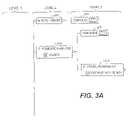
- FIGS. 3A , 3 B and 3 Ctogether show the EPT of FIG. 2B in the expanded form where first, second and third level (L 1 , L 2 and L 3 ) nodes of the DTV analysis system are displayed with different error conditions represented;
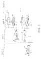
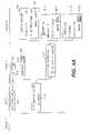
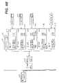
- FIGS. 4A , 4 B and 4 Ctogether show the EPT of FIGS. 3A–3C in a further expanded form with first, second, third and fourth level (L 1 , L 2 , L 3 and L 4 ) nodes displayed; and
- FIG. 5is a partial image of a display screen including an EPT and an associated hook window according to an embodiment of the invention.
- FIGS. 6–9are different examples of screen images for different DTV signal samples, including an EPT and an associated hook window according to the embodiments of the invention.
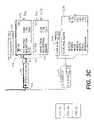
- FIG. 10is a functional block diagram of hardware and/or software usable to generate and display an EPT according to an embodiment of the present invention.
- FIG. 1shows a general structure of an EPT applied to represent condition information of components of a certain system according to an embodiment of the present invention.
- various components of the system to be analyzedare presented in an EPT fashion on a display device such as a computer screen.
- a display devicesuch as a computer screen.
- At the first levelat least one main component (Component A) is represented as node 10 ; at the next lower level (second level), sub-components of Component A are represented as nodes 20 , 21 . . . and are labeled as Components B 1 , B 2 . . . ; at the next lower level, sub-components of each of Components B 1 , B 2 . . .
- the main component(s) of the system to be analyzed and any subsequent lower level sub-components of the main components of the systemare represented as nodes branching off in a tree-like fashion to form the EPT.
- At least one of the main components of the systemincludes a status indicator 14 and an expansion activator 11 .
- Each of the sub-components of the systemalso includes a status indicator 14 , but may or may not include an expansion activator 11 depending on the need and system configuration.
- a status indicator 14indicates the status or condition information of the corresponding node. Any number of different states/conditions may be indicated using the status indicator 14 .
- the indicator 14can be configured to include a light emitting diode (LED) or some other mechanism.
- the indicator 14can assume different colors to denote any number of different states (e.g., normal or alert states) in lower level nodes of the EPT. For instance, a node taking on a first color, e.g., red, can indicate that an alert condition presently exists in it or a lower level node in the EPT that reports to it, which may connote an error condition in a lower level node in the EPT.
- a node taking on a second colorcan indicate that an alert condition arose (in it or a lower node reporting to it) since the last reset of the corresponding indictor 14 but that the alert condition does not presently exist.
- a node taking on a third colore.g., green, can indicate that no alert condition has arisen (in it or a lower node reporting to it) since the last reset through and including the present moment. That is, regardless of the number of different states that a status indicator can indicate, the status indicator generally always indicate the highest alert state from the different states of the current node and its lower (child) node(s).
- the highest priority alertis the first color (red), then the next highest priority is the second color (yellow) followed by the third color (green).
- the first coloris highest
- the second coloris second highest
- the third coloris third highest.
- each indicator 14 in FIG. 1is depicted to have a circular configuration, the present invention is not limited to such, and the indicator 14 can have any configuration, shape, color, size, etc.
- the indication of the indicator 14is not limited to the use of a color, but can be represented in any other manner.
- the shape, size and/or boundary format of each nodemay change appropriately to depict different condition information of the node.
- a particular indication of the indicator 14can be configured to trigger a display of a separate indicating mechanism or a generation of an audible sound.
- the activation of the indicator 14 in the highest priority alert statemay trigger a separate window or icon to pop-up on a screen or a generation of an alarm sound to alert the user of the highest priority alert state.
- other variationsare possible.
- certain edges or the body of each nodecan take on the same color as the corresponding indicator 14 to better communicate the condition information.
- the left edge 16 and top edge 18 of a body 12 of each nodecan take the same color as the indicator 14 of that node.
- An expansion activator 11is used to expand the corresponding node of the EPT to the next lower level nodes, and can be a button, a switch, or any other means.
- each expansion activator 11in its unexpanded form, is depicted as a square with a dot 11 a in the center, but can be depicted in any other matter.
- the dotdenotes that this button, when activated (e.g., with a pointing device, a mouse, a touch screen, etc.) will expand the EPT to display the next lower level nodes. If so expanded, the expansion activator 11 would indicate that the node is in the expanded form and this expansion indication can be made in any manner. For instance, the dot in the center (i.e., as a collapse button) of the expansion activator 11 may not show as in FIG. 1 .
- line segments 19 connecting the different nodescan be displayed with the same color(s) as the colors of the associated nodes. In places where line segments 19 are allocated with more than one color, then the color of the highest priority among the allocated colors will be used to color those places of the line segments 19 . This will be explained in more detail later referring to an example in FIG. 2A .
- some or all of the nodesmay include a hook button or switch 40 that causes a graphics screen, a hook window or some other window to be displayed. Such windows can display additional detailed condition information and/or any other information about the associated node.
- some or all of the nodesmay include a reset button or switch 41 for resetting the status of the associated indicator of the node, and/or a validity indicator 42 which indicates the validity of data being used by an analysis engine to determine the state of the associated node. Given a node with both the status indicator 14 and the validity indicator 42 , that status indicator 14 then indicates the combined status of (1) the status of the current node indicated by the validity indicator 42 and (2) the status of its child node(s).
- the EPT according to an embodiment of the present inventionis dynamic such that any number of nodes and levels can be selectively added or removed and that the existing interconnections between the nodes may be changed selectively in real or non-real time, as circumstances change.
- FIG. 2Ais a depiction of an unexpanded EPT in which only the first level L 1 node or root node 100 is displayed on a display device.
- the node 100has the legend “Stream Analysis”.
- the node 100has a body 102 , a status indicator 104 and an expansion activator or button 110 which respectively correspond to a body 12 , a status indicator 14 , and an expansion activator 11 in FIG. 1 .
- the indicator 104assumes different colors to denote normal or alert states in lower level nodes of the EPT.
- a node taking on a first colore.g., red
- a node taking on a second colore.g., yellow
- an alert condition arosein it or a lower node reporting to it
- the last reset of the indictor 104since the last reset of the indictor 104 but that the alert condition does not presently exist.
- a node taking on a third colorcan indicate that no alert condition has arisen (in it or a lower node reporting to it) since the last reset through and including the present moment.
- the highest priority alertis the first color (red), then the next highest priority is the second color (yellow) followed by the third color (green).
- the left edge 106 and top edge 108 of the body 102 of the node 100take the same color as the indicator 104 .
- FIG. 2Bis a depiction of the EPT of FIG. 2A in an expanded form with first and second level (L 1 and L 2 ) nodes displayed.
- the first level L 1is depicted in the same manner as in FIG. 2A except for the expansion button 110 ′.
- the expansion button 110 ′is not depicted with a dot in the center to reflect that the EPT has been expanded to show the first and second levels L 1 and L 2 .
- FIG. 2Bmay resemble an organizational chart.
- nothing about the known organizational chartssuggests the reporting of status alerts from a lower level to a higher level (an aspect of the invention), nor the use of color-keyed connecting lines to help quickly locate the source of the status alert being reported (another aspect of the invention).
- the second level L 2 in FIG. 2Bincludes nodes 202 , 204 , 206 , 208 and 210 . These nodes include indicators 212 , 214 , 216 , 218 and 220 , respectively, that operate like the indicator 104 . Each second level node also includes an expansion activator or button 225 . The tops and sides (unnumbered for simplicity) of the nodes in the second level can take the same color as their corresponding indicator, respectively.
- the indicators 214 and 220 for the nodes 204 having the legend “PCR/Buffer Analysis” and 210 having the legend “Statistics”are depicted as being green to represent no alert condition having arisen in a lower level of the EPT since the last reset through and including the present moment.
- the indicators 212 and 216 for the nodes 202 having the legend “Auto Trigger” and 206 having the legend “PSIP Analysis”are depicted as being yellow to represent an alert condition having arisen in a lower level of the EPT since the last reset of the indictor 104 but which does not presently exist.
- the indicator 218 for the node 208 having the legend “MPEG-2 Analysis”is depicted as being red to represent an alert condition that presently exists in a lower level node in the EPT.
- a different number of nodes in the second level L 2 corresponding to different componentscan be used according to the present invention.
- the line segments 222 , 223 , 224 and 226 from the node 100 to the node 208take on the red color corresponding to the state (red) of the indicator 218 .
- the line segments 228 , 230 , 232 and 234take on the yellow color corresponding to the states (yellow) of the indicators 216 and 212 , respectively.
- line segments 238 and 240take on the green color corresponding to the state of the indicator 220
- the line segment 236take on the green color corresponding to the state of the indicator 214 .
- the colors of the line segmentsare controlled by the relative priority of the states of the indicators to which the line segments connect. For instance, although all three red, green yellow colors are allocated to the line segment 222 , the line segment 222 takes on the red color since it has the highest priority among the three colored states.
- the nodes 206 and 210include hook buttons 242 and 244 that have a caricature of a textual data display upon them. Clicking upon or activating the hook buttons 242 and 244 can cause a hook window (see the discussion of FIG. 6 below) to open in a predetermined area on a display screen that includes the EPT. In particular, clicking on the hook button 242 can cause an electronic program guide (EPG) to be displayed in the hook window. The generation of an EPG is well known. Clicking on the hook button 244 can cause a PID (acronym for packet identifier) usage graphic to be displayed in the hook window.
- EPGelectronic program guide
- the node 204is depicted as having a second indicator or validity indicator 246 associated with the legend “Validity.”
- the validity indicator 246is contained within a reset button 248 .
- a reset button(such as 248 ) can reset the status of the associated indicator (such as 246 is associated with reset button 248 ) to the green alert status when clicked.
- the validity indicator 246indicates the status of the current node (node 204 ) only, whereas the status indicator 214 indicates the combined status of the current node (as indicated by the validity indicator 246 ) and its child nodes. For instance, if the status indicator 214 is green, this means that all child nodes of the node 204 and the validity indicator 246 are green. If the validity indicator 246 is red, then the status indicator 214 will be red because its validity check has failed. In this example, none of the child node indicators would be meaningful since the data (while the indicator 246 is red) being sent to the child node analysis engines are not valid. If the status indicator 214 is red while the validity indicator 246 is green, this means that at least one of its child nodes has detected some error. The status indicator 214 may not be green when the validity indicator 246 is not green, and the status indicator 214 may not be green when any of its child nodes is not green.
- the hook buttons 242 and 244correspond to the hook button 40 in FIG. 1
- the validity indicator 246corresponds to the validity indicator 42 in FIG. 1
- the reset button 248corresponds to the reset button 41 in FIG. 1 .
- the auto trigger node 202 of FIG. 2B and its child node or leaf node 350represent functionalities of the monitoring/diagnostic device that include automatically recording a signal, activating one or both of an audible and a visual alarm, and automatically controlling a contact closure to occur in response to one or more trigger events.
- the indicator 212 of the auto trigger node 202can take on a green alert state when no triggers have occurred since the last reset.
- the indicator 212can also take on a red alert state if a trigger has occurred since the last reset.
- the indicator 212can take on a yellow alert state if a trigger event occurs and the current mode of the monitoring/diagnostic device precludes at least one automatic response to it.
- FIG. 2Cis a depiction of the EPT of FIG. 2B with different error conditions represented.
- the indicator 218 of node 208takes on the yellow state from the previous red state.
- the line segments 222 , 223 , 224 and 226take on the yellow color corresponding to the states of the indicator 218 of node 208 .
- the indicator 104 in the node 100also takes on the yellow color because that is the highest priority being reported/indicated in the second level L 2 of the EPT.
- the left edges and top edges of the nodes 100 and 208have correspondingly changed color from red to yellow.
- FIGS. 3A , 3 B and 3 C togetherare a depiction of the EPT of FIG. 2B in a further expanded form with first, second and third level (L 1 , L 2 and L 3 ) nodes displayed, albeit with different error conditions represented, and FIGS. 4A , 4 B and 4 C together are a depiction of the EPT of FIGS. 3A–3C in still further expanded form with first through fourth level nodes displayed, all according to an embodiment of the present invention.
- node 208has been depicted in the red alert state. Hence, line segments 222 , 223 , 224 and 226 are shown in red. And node 100 is shown in red because in it or in a node reporting to it (namely node 208 ) there presently exists a red alert condition.
- the nodes 202 , 204 , 206 and 210have been depicted in the green alert state. Hence the remaining line segments between the nodes 202 , 204 , 206 and 210 are shown in green.
- the third level L 3 node reporting to the Auto Trigger node 202includes node 350 (having the legend “Configure”).
- the third level L 3 nodes reporting to the PCR/Buffer Analysis node 204include node 332 (having the legend “Virtual Program 0x3”) and node 334 (having the legend “Configure”).
- the third level L 3 nodes reporting to the PSIP Analysis node 206include node 302 (having the legend “MGT,” the acronym for master guide table), node 304 (having the legend “TVCT,” the acronym for terrestrial virtual channel table), node 306 (having the legend “STT,” the acronym for system time table), node 308 (having the legend “RRT,” the acronym for region rating table) node 310 (having the legend “EIT,” the acronym for event information table) and node 312 (having the legend “Configure”).
- MTTthe acronym for master guide table
- TVCTthe acronym for terrestrial virtual channel table
- node 306having the legend “STT,” the acronym for system time table
- node 308having the legend “RRT,” the acronym for region rating table
- node 310having the legend “EIT,” the acronym for event information table
- node 312having the legend “Configure”.
- the third level L 3 nodes reporting to the MPEG-2 Analysis node 208include node 314 (having the legend “PAT,” the acronym for program allocation table), node 316 (having the legend “PMT,” the acronym for program map table) and node 318 (having the legend “Configure”).
- the third level L 3 nodes reporting to the Statistics node 210includes node 346 (having the legend “Configure”) and node 354 (having the legend “General Alerts”).
- the third level L 3 node 314(reporting to node 208 ) is depicted in the red alert state, which has caused the node 208 to be depicted in the red alert state, and which in turn has caused the node 100 to be depicted in the red alert state.
- the line segments 319 , 320 and 322 between nodes 314 and 208are also depicted in the red alert state.
- the third level L 3 node 316is depicted in the yellow alert state. As a result, the line segments 324 and 326 between the nodes 316 and 208 are depicted in the yellow alert state.
- the configure node 318(to be discussed in more detail below) does not take on an alert state, hence the line segments 328 and 330 have been depicted in black as has the left edge and top edge of the configure node 318 .
- the nodes 314 and 316 in FIG. 3Chave expansion buttons 336 and 338 , respectively.
- node 332is shown in the expanded state with node 410 (having the legend “PCR Analysis,” PCR being the acronym for program clock reference), node 412 (having the legend “Video 0x31”) and node 414 (having legend “AC3 0x34”) reporting to it.
- nodes 410 , 412 and 414are depicted in the green alert state, as are the lines connecting them to node 332 .
- Nodes 410 , 412 and 414may include, respectively, hook buttons 416 , 418 and 420 that each bear a caricature of a waveform or some other graphics.
- Clicking on or activating the hook button 416may cause a graphic of the PCR analysis to be displayed in a hook window.
- Clicking on the hook button 418may cause the video image to be displayed in a hook window.
- Clicking on the hook button 420may cause a graphic of the audio buffer usage to be displayed in a hook window.
- FIG. 4Ban expansion button has not been depicted for node 308 .
- each of nodes 302 , 304 , 306 and 310have an expansion button.
- the absence of an expansion button for the node 308 or any other appropriate nodeindicates that the corresponding table, e.g., RRT for node 308 , has not been received in the DTV packet multiplex being analyzed, hence no fourth level L 4 node has been depicted as reporting to node 308 .
- any node in the EPT of the present inventionmay expand to one or more next lower level nodes if needed.
- the configure nodes 312 , 318 , 334 , 346 and 350can control what analysis engines will be enabled, and in some instances, permit some parameters of the analyses to be set. Hence, a configure node controls what nodes will be depicted as reporting to the next highest level node in the EPT.
- configure node 312 in FIG. 4Bincludes a button 340 that, when clicked, opens a dialog window (not depicted) that permits a user to turn on/off the analysis engine that monitors compliance with the issuance intervals defined for the other node components such as MGT, TVCT, STT, RRT, EIT, etc.
- the dialog windowcan permit the user to customize the interval definitions, but can default to those set by the American Television Standards Committee (ATSC) or other predetermined parameters.
- a button 342 of the configure node 318 in FIG. 4Cmay open a similar dialog window as the configure node 312 .
- the configure node 334 in FIG. 4Aincludes a button 344 that, when clicked, opens a dialog window (not depicted) that can permit a user to turn on/off certain analysis engines.
- thesecan include, but are not limited to, a continuity count checking engine, PCR/Jitter analysis engine, video buffer underflow/overflow analysis engine, audio buffer underflow/overflow analysis engine.
- the configure node 346 in FIG. 4Cincludes a button 348 that, when clicked, opens a dialog window (not depicted) that can permit a user to turn on/off certain analysis engines that produce alerts when certain types of packets (e.g., audio, video, PSIP tables, MPEG-2, data, null, unknown, etc.) exceed user-defined or default thresholds.
- the alertscan be set for an aggregate of all monitored virtual programs and a different set of alerts can be set for individual virtual programs.
- node 422 in FIG. 4Cpresents PID usage information for a single virtual program 0x3 using a different set of alerts than represented by the node 354 .
- the configure node 350 in FIG. 4Cincludes a button 352 that, when clicked, opens a dialog window (not depicted) that permits a user to turn on/off analysis engines that recognize trigger events; and responses associated with the triggering event.
- the dialog windowalso permits the user to set parameters that the analysis engines use to recognize the trigger events.
- a particular example of a response to a trigger eventcan include paging/communicating with a technician.
- Examples of events to automatically trigger recording of the DTV signalinclude, but are not limited to: the audio buffer being out of bounds; a reset of the video buffer analysis engine; the audio buffer being back in bounds; the video buffer being out of bounds; the video buffer being back in bounds; PCR jitter being out of bounds; PCR jitter being back in bounds; PCR frequency offset being out of bounds; PCR frequency offset being back in bounds; an audio PID being found; an error reading a properties file; an error reading a product information file; encountering a MainFrame already registered; an error shutting down a listener; a DTVControlComponent dequeueEvent interrupted while waiting for event; a DTVControlEventNotifier ThreadDeath; a Disabling of lip sync; and a DTVPlayer.getChannelValue NumberFormatException.
- clicking on one of the expansion buttonswill open a fourth level L 4 node.
- clicking on one of the expansion buttons 336 and 338will open a fourth level node 402 (having the legend “PID 0x0”) or node 404 (having the legend “PID 0x30”)g. 4 C.
- the expansion buttons 336 and 338are correspondingly shown in the expanded states (without the dot in the center) as item nos. 336 ′ and 338 ′.
- the left edge and top edge of the fourth level L 4 node 402are shown in the red alert state as is the line connecting node 402 to node 314 .
- the left edge and top edge of the fourth level L 4 node 404are shown in the yellow alert state as is the line connecting node 404 to node 316 .
- the red alert state of node 402is reported up to node 100 via nodes 314 and 208 .
- the yellow alert state of node 404is reported to node 316 but is not as high a priority as the red alert state of node 402 , hence node 208 takes on the red alert state rather than the yellow alert state.
- the fourth level L 4 nodes 402 and 404may include hook buttons 406 and 408 , respectively. As discussed above, clicking on one of these hook buttons can cause the contents of the associated packet to be displayed in a hook window.
- FIG. 5shows an example of a screen image showing at least a portion of the EPT of FIGS. 2A–4C , including an example of a hook window 604 displayed in response to the actuation of a hook button discussed above, according to an embodiment of the present invention.
- the hook window 604is shown in the partial image 600 of a monitoring/diagnostic device display screen that includes a partial EPT 602 (showing nodes 100 , 206 and 208 ).
- the example contents 606being depicted in the hook window 604 . Once the hook window 604 is opened, it will stay open until the close button 612 is clicked.
- An export button 614is provided to permit the contents in the currently displayed hook window, i.e., the one on top, to be exported, e.g., to a file to be saved.
- FIGS. 6–9are alternate images depicting information about different DTV signal samples of a display screen including an EPT and an associated hook window according to an embodiment of the invention. These figures are provided merely to present different examples of the present invention, and thus, the detailed discussion thereof is omitted.
- a digital television (DTV) diagnostic instrument(and the software embodied therein) that can display the EPT according to the embodiments of the present invention can use known hardware programmed according to the invention.
- An example of such hardware and/or softwareis depicted in FIG. 11 as a system 700 .
- the system 700 of FIG. 11includes a computer/controller 702 having input/out circuitry 708 , a processor 706 , one or more memory devices 710 and a DTV receiver 712 , all operatively coupled.
- the computer 702is operatively connected to a radio frequency (RF) antenna 724 and/or to a coaxial cable 726 via which the computer 702 receives, e.g., an 8 vestigial side band (VSB) signal.
- RFradio frequency
- VSBvestigial side band
- the output of the diagnostic instrumentis provided to an audio output unit 722 and/or a video display device (VDD) 716 such as a liquid crystal display (LCD) device or cathode ray tube (CRT).
- VDDvideo display device
- LCDliquid crystal display
- CRTcathode ray tube
- Portions of DTV signals received via the antenna 724 and/or the coaxial cable 726can be saved to or retrieved from a storage unit 718 such as a disk storage and/or from a network 720 via a connection such as an ethernet connection.
- the system 700can also be configured to be easily portable.
- the DTV receiver 712can be, e.g., DTVCARD A1000 model of circuit board manufactured and sold by TRIVENI DIGITAL INC.
- the processor 706can be of the PENTIUM family of processors sold by INTEL INC., e.g., a 450 MHz PENTIUM III processor, preferably running a WINDOWS 98 operating system manufactured and sold by the MICROSOFT CORPORATION in the case where the DTV A1000 card is employed as the DTV receiver 712 .
- transport streamscan be input to the hardware/software by any means, and not necessarily via the DTV card.
- Other ways of delivering the transport streamsmay be by, e.g., TCP/IP (or UDP), file based input, other physical devices such as ASI & SMPTE 310 cards, USB and PCMCIA.
- the analysis engines employed to generate the data by which the nodes take on one of the alert statesare known. For example, they can be found in the STREAMSCOPE family of Real-Time Monitors and Analyzers for ATSC MPEG-2 Transport Streams, manufactured and marketed by TRIVENI DIGITAL INC. Such analysis engines can be augmented or modified to display the alert states in an EPT fashion according to the present invention using known hardware and/or computer programming. Any known computer program language may be used in the present invention to implement the invention.
- each node in the Error Propagation Treereports the worst error status of any of its children. This can be done in one of two ways. The first way is to have a child node recursively report its current status up to the parent and to have the parent keep a state of all of its children and determine if its state (the parent's) has changed by the notification from its child. Then the parent can send notification of its change up to its parent (the grandparent of the children nodes).
- An advantage to this methodis that there is not much checking that needs to be done.
- a disadvantageis that if not implemented correctly, parents can lose synchronization with children.
- the second wayis to have a child node recursively inform its parent whether the child node has changed states.
- Each successive parent nodecontinues to propagate this information (namely, news of a state change) up until the root node level, then recursively queries its children for their new state to determine whether its own state has changed and, if so, how.
- An advantage of this methodis that it will never be out of synchronization with its children.
- a disadvantage of this methodis that the node needs to query all of its children every time a state has changed. Any known techniques, software, and/or hardware can be used to implemented the first and second ways by one skilled in the art.
- the EPT techniquecan be used to analyze any system, product or signal and the EPT can have any number of nodes and levels corresponding to the components and structure of the system, product or signal to be analyzed.
- the EPTprovides an effective and powerful way to quickly analyze and diagnose the conditions and/or errors in the entity being examined.
Landscapes
- Engineering & Computer Science (AREA)
- Health & Medical Sciences (AREA)
- Biomedical Technology (AREA)
- General Health & Medical Sciences (AREA)
- Multimedia (AREA)
- Signal Processing (AREA)
- User Interface Of Digital Computer (AREA)
Abstract
Description
Claims (29)
Priority Applications (1)
| Application Number | Priority Date | Filing Date | Title |
|---|---|---|---|
| US10/116,070US7215360B2 (en) | 2001-04-06 | 2002-04-05 | Error propagation tree technology |
Applications Claiming Priority (2)
| Application Number | Priority Date | Filing Date | Title |
|---|---|---|---|
| US28180401P | 2001-04-06 | 2001-04-06 | |
| US10/116,070US7215360B2 (en) | 2001-04-06 | 2002-04-05 | Error propagation tree technology |
Publications (2)
| Publication Number | Publication Date |
|---|---|
| US20020158969A1 US20020158969A1 (en) | 2002-10-31 |
| US7215360B2true US7215360B2 (en) | 2007-05-08 |
Family
ID=26813869
Family Applications (1)
| Application Number | Title | Priority Date | Filing Date |
|---|---|---|---|
| US10/116,070Expired - LifetimeUS7215360B2 (en) | 2001-04-06 | 2002-04-05 | Error propagation tree technology |
Country Status (1)
| Country | Link |
|---|---|
| US (1) | US7215360B2 (en) |
Cited By (90)
| Publication number | Priority date | Publication date | Assignee | Title |
|---|---|---|---|---|
| US20030197732A1 (en)* | 2002-04-23 | 2003-10-23 | Gupta Jimmy Rohit | Cross table analysis display |
| US20050081215A1 (en)* | 2003-10-09 | 2005-04-14 | International Business Machines Corporation | Computer-implemented method, system and program product for determining a message quantity for program code |
| US7945817B1 (en)* | 2004-04-30 | 2011-05-17 | Sprint Communications Company L.P. | Method and system for automatically recognizing alarm patterns in a communications network |
| US20110119530A1 (en)* | 2009-11-17 | 2011-05-19 | Computer Associates Think, Inc. | Service modeling impact analysis |
| US20110161740A1 (en)* | 2009-12-28 | 2011-06-30 | Fujitsu Limited | Apparatus and method for selecting candidate for failure component |
| CN102291591A (en)* | 2011-06-24 | 2011-12-21 | 广州视源电子科技有限公司 | Television software function compilation-free configuration method and device thereof |
| US9055028B1 (en) | 2011-02-02 | 2015-06-09 | TV Band Service, LLC | Flexibly targeting information sent over a broadcast communications medium |
| US9253124B2 (en) | 2012-05-15 | 2016-02-02 | TV Band Service, LLC | Techniques for sending and relaying information over broadcast and non-broadcast communications media |
| US10388067B2 (en) | 2013-07-31 | 2019-08-20 | Splunk Inc. | Conveying machine data to a user via attribute mapping in a three-dimensional model |
| US10999152B1 (en) | 2020-04-20 | 2021-05-04 | Servicenow, Inc. | Discovery pattern visualizer |
| US11025508B1 (en) | 2020-04-08 | 2021-06-01 | Servicenow, Inc. | Automatic determination of code customizations |
| US11095506B1 (en) | 2020-07-22 | 2021-08-17 | Servicenow, Inc. | Discovery of resources associated with cloud operating system |
| US11150784B1 (en) | 2020-09-22 | 2021-10-19 | Servicenow, Inc. | User interface elements for controlling menu displays |
| US11216271B1 (en) | 2020-12-10 | 2022-01-04 | Servicenow, Inc. | Incremental update for offline data access |
| US11245591B1 (en) | 2020-09-17 | 2022-02-08 | Servicenow, Inc. | Implementation of a mock server for discovery applications |
| US11258847B1 (en) | 2020-11-02 | 2022-02-22 | Servicenow, Inc. | Assignments of incoming requests to servers in computing clusters and other environments |
| US11263195B2 (en) | 2020-05-11 | 2022-03-01 | Servicenow, Inc. | Text-based search of tree-structured tables |
| US11272007B2 (en) | 2020-07-21 | 2022-03-08 | Servicenow, Inc. | Unified agent framework including push-based discovery and real-time diagnostics features |
| US11269618B1 (en) | 2020-12-10 | 2022-03-08 | Servicenow, Inc. | Client device support for incremental offline updates |
| US11277369B1 (en) | 2021-03-02 | 2022-03-15 | Servicenow, Inc. | Message queue architecture and interface for a multi-application platform |
| US11277475B1 (en) | 2021-06-01 | 2022-03-15 | Servicenow, Inc. | Automatic discovery of storage cluster |
| US11277321B2 (en) | 2020-07-06 | 2022-03-15 | Servicenow, Inc. | Escalation tracking and analytics system |
| US11277359B2 (en) | 2020-06-11 | 2022-03-15 | Servicenow, Inc. | Integration of a messaging platform with a remote network management application |
| US11275580B2 (en) | 2020-08-12 | 2022-03-15 | Servicenow, Inc. | Representing source code as implicit configuration items |
| US11281442B1 (en) | 2020-11-18 | 2022-03-22 | Servicenow, Inc. | Discovery and distribution of software applications between multiple operational environments |
| US11296922B2 (en) | 2020-04-10 | 2022-04-05 | Servicenow, Inc. | Context-aware automated root cause analysis in managed networks |
| US11301365B1 (en) | 2021-01-13 | 2022-04-12 | Servicenow, Inc. | Software test coverage through real-time tracing of user activity |
| US11301503B2 (en) | 2020-07-10 | 2022-04-12 | Servicenow, Inc. | Autonomous content orchestration |
| US11301435B2 (en) | 2020-04-22 | 2022-04-12 | Servicenow, Inc. | Self-healing infrastructure for a dual-database system |
| US11301271B1 (en) | 2021-01-21 | 2022-04-12 | Servicenow, Inc. | Configurable replacements for empty states in user interfaces |
| US11343079B2 (en) | 2020-07-21 | 2022-05-24 | Servicenow, Inc. | Secure application deployment |
| US11342081B2 (en) | 2020-10-21 | 2022-05-24 | Servicenow, Inc. | Privacy-enhanced contact tracing using mobile applications and portable devices |
| US11363115B2 (en) | 2020-11-05 | 2022-06-14 | Servicenow, Inc. | Integrated operational communications between computational instances of a remote network management platform |
| US11372920B2 (en) | 2020-08-31 | 2022-06-28 | Servicenow, Inc. | Generating relational charts with accessibility for visually-impaired users |
| US11379089B2 (en) | 2020-07-02 | 2022-07-05 | Servicenow, Inc. | Adaptable user interface layout for applications |
| US11392768B2 (en) | 2020-05-07 | 2022-07-19 | Servicenow, Inc. | Hybrid language detection model |
| US11418586B2 (en) | 2021-01-19 | 2022-08-16 | Servicenow, Inc. | Load balancing of discovery agents across proxy servers |
| US11418571B1 (en) | 2021-07-29 | 2022-08-16 | Servicenow, Inc. | Server-side workflow improvement based on client-side data mining |
| US11449535B2 (en) | 2020-07-13 | 2022-09-20 | Servicenow, Inc. | Generating conversational interfaces based on metadata |
| US11451573B2 (en) | 2020-06-16 | 2022-09-20 | Servicenow, Inc. | Merging duplicate items identified by a vulnerability analysis |
| US11470107B2 (en) | 2020-06-10 | 2022-10-11 | Servicenow, Inc. | Matching configuration items with machine learning |
| US11513885B2 (en) | 2021-02-16 | 2022-11-29 | Servicenow, Inc. | Autonomous error correction in a multi-application platform |
| US11516307B1 (en) | 2021-08-09 | 2022-11-29 | Servicenow, Inc. | Support for multi-type users in a single-type computing system |
| US11582106B2 (en) | 2020-07-22 | 2023-02-14 | Servicenow, Inc. | Automatic discovery of cloud-based infrastructure and resources |
| US11582317B1 (en) | 2022-02-07 | 2023-02-14 | Servicenow, Inc. | Payload recording and comparison techniques for discovery |
| US11625141B2 (en) | 2020-09-22 | 2023-04-11 | Servicenow, Inc. | User interface generation with machine learning |
| US11632300B2 (en) | 2020-07-16 | 2023-04-18 | Servicenow, Inc. | Synchronization of a shared service configuration across computational instances |
| US11632303B2 (en) | 2020-10-07 | 2023-04-18 | Servicenow, Inc | Enhanced service mapping based on natural language processing |
| US11630717B2 (en) | 2021-01-06 | 2023-04-18 | Servicenow, Inc. | Machine-learning based similarity engine |
| US11635953B2 (en) | 2021-05-07 | 2023-04-25 | Servicenow, Inc. | Proactive notifications for robotic process automation |
| US11635752B2 (en) | 2021-05-07 | 2023-04-25 | Servicenow, Inc. | Detection and correction of robotic process automation failures |
| US11640369B2 (en) | 2021-05-05 | 2023-05-02 | Servicenow, Inc. | Cross-platform communication for facilitation of data sharing |
| US11693831B2 (en) | 2020-11-23 | 2023-07-04 | Servicenow, Inc. | Security for data at rest in a remote network management platform |
| US11734381B2 (en) | 2021-12-07 | 2023-08-22 | Servicenow, Inc. | Efficient downloading of related documents |
| US11734150B1 (en) | 2022-06-10 | 2023-08-22 | Servicenow, Inc. | Activity tracing through event correlation across multiple software applications |
| US11734025B2 (en) | 2020-10-14 | 2023-08-22 | Servicenow, Inc. | Configurable action generation for a remote network management platform |
| US11748115B2 (en) | 2020-07-21 | 2023-09-05 | Servicenow, Inc. | Application and related object schematic viewer for software application change tracking and management |
| US11762717B2 (en) | 2018-12-11 | 2023-09-19 | DotWalk, Inc. | Automatically generating testing code for a software application |
| US11762668B2 (en) | 2021-07-06 | 2023-09-19 | Servicenow, Inc. | Centralized configuration data management and control |
| US11829233B2 (en) | 2022-01-14 | 2023-11-28 | Servicenow, Inc. | Failure prediction in a computing system based on machine learning applied to alert data |
| US11831729B2 (en) | 2021-03-19 | 2023-11-28 | Servicenow, Inc. | Determining application security and correctness using machine learning based clustering and similarity |
| US11868593B2 (en) | 2020-11-05 | 2024-01-09 | Servicenow, Inc. | Software architecture and user interface for process visualization |
| US11921878B2 (en) | 2021-01-21 | 2024-03-05 | Servicenow, Inc. | Database security through obfuscation |
| US11960353B2 (en) | 2021-11-08 | 2024-04-16 | Servicenow, Inc. | Root cause analysis based on process optimization data |
| US11989538B2 (en) | 2022-06-21 | 2024-05-21 | Servicenow, Inc. | Orchestration for robotic process automation |
| US12001502B2 (en) | 2022-01-11 | 2024-06-04 | Servicenow, Inc. | Common fragment caching for web documents |
| US12039328B2 (en) | 2022-09-30 | 2024-07-16 | Servicenow, Inc. | Configuration items for supporting automations and efficacies thereof |
| US12056473B2 (en) | 2022-08-01 | 2024-08-06 | Servicenow, Inc. | Low-code / no-code layer for interactive application development |
| US12072775B2 (en) | 2022-12-07 | 2024-08-27 | Servicenow, Inc. | Centralized configuration and change tracking for a computing platform |
| US12095634B2 (en) | 2022-08-12 | 2024-09-17 | Servicenow, Inc. | Hybrid request routing system |
| US12099567B2 (en) | 2021-12-20 | 2024-09-24 | Servicenow, Inc. | Viewports and sub-pages for web-based user interfaces |
| US12131168B1 (en) | 2023-04-18 | 2024-10-29 | Servicenow, Inc. | Outcome-oriented automation platform |
| US12141048B2 (en) | 2022-10-12 | 2024-11-12 | Servicenow, Inc. | Machine learning model for determining software defect criticality |
| US12147487B2 (en) | 2022-12-07 | 2024-11-19 | Servicenow, Inc. | Computationally efficient traversal of virtual tables |
| US12192245B2 (en) | 2023-01-23 | 2025-01-07 | Servicenow, Inc. | Control of cloud infrastructure configuration |
| US12222834B2 (en) | 2023-05-24 | 2025-02-11 | Servicenow, Inc. | Discovery troubleshooting based on machine learning |
| US12231508B2 (en) | 2022-07-12 | 2025-02-18 | Servicenow, Inc. | Rapid error detection through command validation |
| US12248361B2 (en) | 2023-07-31 | 2025-03-11 | Servicenow, Inc. | Parallelized exception handling for large datasets |
| US12254352B2 (en) | 2021-10-28 | 2025-03-18 | Servicenow, Inc. | Reduced memory utilization for data analytics procedures |
| US12254014B1 (en) | 2024-02-23 | 2025-03-18 | Servicenow, Inc. | Document creation with guided generative artificial intelligence |
| US12254063B2 (en) | 2021-03-22 | 2025-03-18 | Servicenow, Inc. | Cross-modality curiosity for sparse-reward tasks |
| US12261904B2 (en) | 2022-01-20 | 2025-03-25 | Servicenow, Inc. | Nested request-response protocol network communications |
| US12294581B2 (en) | 2023-06-14 | 2025-05-06 | Servicenow, Inc. | Identifying security vulnerabilities based on access control lists |
| US12299419B2 (en) | 2023-01-26 | 2025-05-13 | Servicenow, Inc. | Unified framework for configuration and deployment of platform intelligence |
| US12362995B2 (en) | 2023-11-06 | 2025-07-15 | Servicenow, Inc. | Reconciliation of partial configuration items |
| US12362844B2 (en) | 2021-08-04 | 2025-07-15 | Triveni Digital Inc. | System and method for visually monitoring media streams |
| US12425195B2 (en) | 2023-07-24 | 2025-09-23 | Service Now, Inc. | Client-side sharing of cryptographic keys |
| US12437158B2 (en) | 2023-07-18 | 2025-10-07 | Servicenow, Inc. | Method for filtering and semi-automatically labeling training data |
| US12438790B1 (en) | 2024-03-26 | 2025-10-07 | Servicenow, Inc. | Network anomaly detection using clustering |
| US12437250B2 (en) | 2021-12-21 | 2025-10-07 | Servicenow, Inc. | Multi-dimensional process mining and analysis |
Families Citing this family (7)
| Publication number | Priority date | Publication date | Assignee | Title |
|---|---|---|---|---|
| CA2545063C (en)* | 2003-11-17 | 2014-04-22 | General Instrument Corporation | Method and apparatuses for using packet data to manage a data stream in a broadband communications system |
| US20090132574A1 (en)* | 2007-11-19 | 2009-05-21 | Microsoft Corporation | Dynamic best practices integration |
| WO2010117129A2 (en) | 2009-04-07 | 2010-10-14 | Lg Electronics Inc. | Broadcast transmitter, broadcast receiver and 3d video data processing method thereof |
| US9658672B2 (en) | 2012-07-30 | 2017-05-23 | Sap Se | Business object representations and detail boxes display |
| US9483086B2 (en) | 2012-07-30 | 2016-11-01 | Sap Se | Business object detail display |
| US20140059488A1 (en)* | 2012-08-21 | 2014-02-27 | Sap Ag | System and method for viewing selected descendant nodes in a tree hierarchy displayed in tabular form |
| US9250781B2 (en) | 2012-10-17 | 2016-02-02 | Sap Se | Method and device for navigating time and timescale using movements |
Citations (26)
| Publication number | Priority date | Publication date | Assignee | Title |
|---|---|---|---|---|
| US4552718A (en)* | 1982-07-01 | 1985-11-12 | Westinghouse Electric Corp. | Method and apparatus for on-line monitoring of the operation of a complex non-linear process control system |
| US4750106A (en)* | 1983-03-11 | 1988-06-07 | International Business Machines Corporation | Disk volume data storage and recovery method |
| US4783730A (en)* | 1986-09-19 | 1988-11-08 | Datapoint Corporation | Input/output control technique utilizing multilevel memory structure for processor and I/O communication |
| US4872167A (en)* | 1986-04-01 | 1989-10-03 | Hitachi, Ltd. | Method for displaying program executing circumstances and an apparatus using the same |
| US5230047A (en)* | 1990-04-16 | 1993-07-20 | International Business Machines Corporation | Method for balancing of distributed tree file structures in parallel computing systems to enable recovery after a failure |
| US5297150A (en)* | 1992-06-17 | 1994-03-22 | International Business Machines Corporation | Rule-based method for testing of programming segments |
| US5392289A (en)* | 1992-11-13 | 1995-02-21 | Ampex Corporation | Error rate measusrement using a comparison of received and reconstructed PN sequences |
| US5631977A (en)* | 1992-12-08 | 1997-05-20 | Fuji Xerox Co., Ltd. | Encoding device for encoding an image along an order determined by resolution tone level |
| US5666480A (en)* | 1991-11-05 | 1997-09-09 | Monolithic System Technology, Inc. | Fault-tolerant hierarchical bus system and method of operating same |
| US5805578A (en)* | 1995-10-27 | 1998-09-08 | International Business Machines Corporation | Automatic reconfiguration of multipoint communication channels |
| US5940083A (en)* | 1997-04-01 | 1999-08-17 | Novell, Inc. | Multi-curve rendering modification apparatus and method |
| US5941955A (en)* | 1994-08-12 | 1999-08-24 | British Telecommunications Public Limited Company | Recovery of distributed hierarchical data access routing system upon detected failure of communication between nodes |
| US6128016A (en)* | 1996-12-20 | 2000-10-03 | Nec Corporation | Graphic user interface for managing a server system |
| US6141767A (en)* | 1998-04-03 | 2000-10-31 | Sony Corporation | Method of and apparatus for verifying reliability of contents within the configuration ROM of IEEE 1394-1995 devices |
| US6144773A (en)* | 1996-02-27 | 2000-11-07 | Interval Research Corporation | Wavelet-based data compression |
| US6253339B1 (en)* | 1998-10-28 | 2001-06-26 | Telefonaktiebolaget Lm Ericsson (Publ) | Alarm correlation in a large communications network |
| US6275801B1 (en)* | 1998-11-03 | 2001-08-14 | International Business Machines Corporation | Non-leaf node penalty score assignment system and method for improving acoustic fast match speed in large vocabulary systems |
| US6353902B1 (en)* | 1999-06-08 | 2002-03-05 | Nortel Networks Limited | Network fault prediction and proactive maintenance system |
| US6499117B1 (en)* | 1999-01-14 | 2002-12-24 | Nec Corporation | Network fault information management system in which fault nodes are displayed in tree form |
| US6707474B1 (en)* | 1999-10-29 | 2004-03-16 | Agilent Technologies, Inc. | System and method for manipulating relationships among signals and buses of a signal measurement system on a graphical user interface |
| US6725405B2 (en)* | 2001-03-15 | 2004-04-20 | International Business Machines Corporation | Apparatus and method for providing a diagnostic problem determination methodology for complex systems |
| US6725235B1 (en)* | 1999-09-22 | 2004-04-20 | Harris-Exigent, Inc. | Dynamic state representation method for complex systems |
| US6751343B1 (en)* | 1999-09-20 | 2004-06-15 | Ut-Battelle, Llc | Method for indexing and retrieving manufacturing-specific digital imagery based on image content |
| US6816993B1 (en)* | 1998-11-25 | 2004-11-09 | Canon Kabushiki Kaisha | Control method of electronic device controllable from external control apparatus by communication |
| US6829299B1 (en)* | 1997-10-02 | 2004-12-07 | Kabushiki Kaisha Toshiba | Variable length decoder and decoding method |
| US6848078B1 (en)* | 1998-11-30 | 2005-01-25 | International Business Machines Corporation | Comparison of hierarchical structures and merging of differences |
- 2002
- 2002-04-05USUS10/116,070patent/US7215360B2/ennot_activeExpired - Lifetime
Patent Citations (26)
| Publication number | Priority date | Publication date | Assignee | Title |
|---|---|---|---|---|
| US4552718A (en)* | 1982-07-01 | 1985-11-12 | Westinghouse Electric Corp. | Method and apparatus for on-line monitoring of the operation of a complex non-linear process control system |
| US4750106A (en)* | 1983-03-11 | 1988-06-07 | International Business Machines Corporation | Disk volume data storage and recovery method |
| US4872167A (en)* | 1986-04-01 | 1989-10-03 | Hitachi, Ltd. | Method for displaying program executing circumstances and an apparatus using the same |
| US4783730A (en)* | 1986-09-19 | 1988-11-08 | Datapoint Corporation | Input/output control technique utilizing multilevel memory structure for processor and I/O communication |
| US5230047A (en)* | 1990-04-16 | 1993-07-20 | International Business Machines Corporation | Method for balancing of distributed tree file structures in parallel computing systems to enable recovery after a failure |
| US5666480A (en)* | 1991-11-05 | 1997-09-09 | Monolithic System Technology, Inc. | Fault-tolerant hierarchical bus system and method of operating same |
| US5297150A (en)* | 1992-06-17 | 1994-03-22 | International Business Machines Corporation | Rule-based method for testing of programming segments |
| US5392289A (en)* | 1992-11-13 | 1995-02-21 | Ampex Corporation | Error rate measusrement using a comparison of received and reconstructed PN sequences |
| US5631977A (en)* | 1992-12-08 | 1997-05-20 | Fuji Xerox Co., Ltd. | Encoding device for encoding an image along an order determined by resolution tone level |
| US5941955A (en)* | 1994-08-12 | 1999-08-24 | British Telecommunications Public Limited Company | Recovery of distributed hierarchical data access routing system upon detected failure of communication between nodes |
| US5805578A (en)* | 1995-10-27 | 1998-09-08 | International Business Machines Corporation | Automatic reconfiguration of multipoint communication channels |
| US6144773A (en)* | 1996-02-27 | 2000-11-07 | Interval Research Corporation | Wavelet-based data compression |
| US6128016A (en)* | 1996-12-20 | 2000-10-03 | Nec Corporation | Graphic user interface for managing a server system |
| US5940083A (en)* | 1997-04-01 | 1999-08-17 | Novell, Inc. | Multi-curve rendering modification apparatus and method |
| US6829299B1 (en)* | 1997-10-02 | 2004-12-07 | Kabushiki Kaisha Toshiba | Variable length decoder and decoding method |
| US6141767A (en)* | 1998-04-03 | 2000-10-31 | Sony Corporation | Method of and apparatus for verifying reliability of contents within the configuration ROM of IEEE 1394-1995 devices |
| US6253339B1 (en)* | 1998-10-28 | 2001-06-26 | Telefonaktiebolaget Lm Ericsson (Publ) | Alarm correlation in a large communications network |
| US6275801B1 (en)* | 1998-11-03 | 2001-08-14 | International Business Machines Corporation | Non-leaf node penalty score assignment system and method for improving acoustic fast match speed in large vocabulary systems |
| US6816993B1 (en)* | 1998-11-25 | 2004-11-09 | Canon Kabushiki Kaisha | Control method of electronic device controllable from external control apparatus by communication |
| US6848078B1 (en)* | 1998-11-30 | 2005-01-25 | International Business Machines Corporation | Comparison of hierarchical structures and merging of differences |
| US6499117B1 (en)* | 1999-01-14 | 2002-12-24 | Nec Corporation | Network fault information management system in which fault nodes are displayed in tree form |
| US6353902B1 (en)* | 1999-06-08 | 2002-03-05 | Nortel Networks Limited | Network fault prediction and proactive maintenance system |
| US6751343B1 (en)* | 1999-09-20 | 2004-06-15 | Ut-Battelle, Llc | Method for indexing and retrieving manufacturing-specific digital imagery based on image content |
| US6725235B1 (en)* | 1999-09-22 | 2004-04-20 | Harris-Exigent, Inc. | Dynamic state representation method for complex systems |
| US6707474B1 (en)* | 1999-10-29 | 2004-03-16 | Agilent Technologies, Inc. | System and method for manipulating relationships among signals and buses of a signal measurement system on a graphical user interface |
| US6725405B2 (en)* | 2001-03-15 | 2004-04-20 | International Business Machines Corporation | Apparatus and method for providing a diagnostic problem determination methodology for complex systems |
Cited By (140)
| Publication number | Priority date | Publication date | Assignee | Title |
|---|---|---|---|---|
| US8261310B2 (en)* | 2002-04-23 | 2012-09-04 | Triveni Digital, Inc. | Cross table analysis display |
| US20030197732A1 (en)* | 2002-04-23 | 2003-10-23 | Gupta Jimmy Rohit | Cross table analysis display |
| US20050081215A1 (en)* | 2003-10-09 | 2005-04-14 | International Business Machines Corporation | Computer-implemented method, system and program product for determining a message quantity for program code |
| US7478364B2 (en)* | 2003-10-09 | 2009-01-13 | International Business Machines Corporation | Computer-implemented method, system and program product for determining a message quantity for program code |
| US7945817B1 (en)* | 2004-04-30 | 2011-05-17 | Sprint Communications Company L.P. | Method and system for automatically recognizing alarm patterns in a communications network |
| US20130124444A1 (en)* | 2009-11-17 | 2013-05-16 | Ca, Inc. | Service modeling impact analysis |
| US8418002B2 (en)* | 2009-11-17 | 2013-04-09 | Ca, Inc. | Service modeling impact analysis |
| US20110119530A1 (en)* | 2009-11-17 | 2011-05-19 | Computer Associates Think, Inc. | Service modeling impact analysis |
| US8683271B2 (en)* | 2009-11-17 | 2014-03-25 | Ca, Inc. | Service modeling impact analysis |
| US20110161740A1 (en)* | 2009-12-28 | 2011-06-30 | Fujitsu Limited | Apparatus and method for selecting candidate for failure component |
| US8984337B2 (en)* | 2009-12-28 | 2015-03-17 | Fujitsu Limited | Apparatus and method for selecting candidate for failure component |
| US9055028B1 (en) | 2011-02-02 | 2015-06-09 | TV Band Service, LLC | Flexibly targeting information sent over a broadcast communications medium |
| CN102291591A (en)* | 2011-06-24 | 2011-12-21 | 广州视源电子科技有限公司 | Television software function compilation-free configuration method and device thereof |
| CN102291591B (en)* | 2011-06-24 | 2013-11-06 | 广州视源电子科技股份有限公司 | Television software function compiling-free configuration method and device |
| US9253124B2 (en) | 2012-05-15 | 2016-02-02 | TV Band Service, LLC | Techniques for sending and relaying information over broadcast and non-broadcast communications media |
| US10403041B2 (en) | 2013-07-31 | 2019-09-03 | Splunk Inc. | Conveying data to a user via field-attribute mappings in a three-dimensional model |
| US10460519B2 (en)* | 2013-07-31 | 2019-10-29 | Splunk Inc. | Generating cluster states for hierarchical clusters in three-dimensional data models |
| US10740970B1 (en)* | 2013-07-31 | 2020-08-11 | Splunk Inc. | Generating cluster states for hierarchical clusters in three-dimensional data models |
| US10810796B1 (en) | 2013-07-31 | 2020-10-20 | Splunk Inc. | Conveying machine data to a user via attribute mappings in a three-dimensional model |
| US11010970B1 (en) | 2013-07-31 | 2021-05-18 | Splunk Inc. | Conveying data to a user via field-attribute mappings in a three-dimensional model |
| US10388067B2 (en) | 2013-07-31 | 2019-08-20 | Splunk Inc. | Conveying machine data to a user via attribute mapping in a three-dimensional model |
| US11762717B2 (en) | 2018-12-11 | 2023-09-19 | DotWalk, Inc. | Automatically generating testing code for a software application |
| US11025508B1 (en) | 2020-04-08 | 2021-06-01 | Servicenow, Inc. | Automatic determination of code customizations |
| US12309028B2 (en) | 2020-04-08 | 2025-05-20 | Servicenow, Inc. | Automatic determination of code customizations |
| US11252047B2 (en) | 2020-04-08 | 2022-02-15 | Servicenow, Inc. | Automatic determination of code customizations |
| US11296922B2 (en) | 2020-04-10 | 2022-04-05 | Servicenow, Inc. | Context-aware automated root cause analysis in managed networks |
| US12273230B2 (en) | 2020-04-10 | 2025-04-08 | Servicenow, Inc. | Context-aware automated root cause analysis in managed networks |
| US10999152B1 (en) | 2020-04-20 | 2021-05-04 | Servicenow, Inc. | Discovery pattern visualizer |
| US11604772B2 (en) | 2020-04-22 | 2023-03-14 | Servicenow, Inc. | Self-healing infrastructure for a dual-database system |
| US11301435B2 (en) | 2020-04-22 | 2022-04-12 | Servicenow, Inc. | Self-healing infrastructure for a dual-database system |
| US11694027B2 (en) | 2020-05-07 | 2023-07-04 | Servicenow, Inc. | Hybrid language detection model |
| US11392768B2 (en) | 2020-05-07 | 2022-07-19 | Servicenow, Inc. | Hybrid language detection model |
| US11263195B2 (en) | 2020-05-11 | 2022-03-01 | Servicenow, Inc. | Text-based search of tree-structured tables |
| US11470107B2 (en) | 2020-06-10 | 2022-10-11 | Servicenow, Inc. | Matching configuration items with machine learning |
| US11671444B2 (en) | 2020-06-10 | 2023-06-06 | Servicenow, Inc. | Matching configuration items with machine learning |
| US11277359B2 (en) | 2020-06-11 | 2022-03-15 | Servicenow, Inc. | Integration of a messaging platform with a remote network management application |
| US11765105B2 (en) | 2020-06-11 | 2023-09-19 | Servicenow, Inc. | Integration of a messaging platform with a remote network management application |
| US11838312B2 (en) | 2020-06-16 | 2023-12-05 | Servicenow, Inc. | Merging duplicate items identified by a vulnerability analysis |
| US11601465B2 (en) | 2020-06-16 | 2023-03-07 | Servicenow, Inc. | Merging duplicate items identified by a vulnerability analysis |
| US11451573B2 (en) | 2020-06-16 | 2022-09-20 | Servicenow, Inc. | Merging duplicate items identified by a vulnerability analysis |
| US11599236B2 (en) | 2020-07-02 | 2023-03-07 | Servicenow, Inc. | Adaptable user interface layout for applications |
| US11379089B2 (en) | 2020-07-02 | 2022-07-05 | Servicenow, Inc. | Adaptable user interface layout for applications |
| US11277321B2 (en) | 2020-07-06 | 2022-03-15 | Servicenow, Inc. | Escalation tracking and analytics system |
| US11301503B2 (en) | 2020-07-10 | 2022-04-12 | Servicenow, Inc. | Autonomous content orchestration |
| US11449535B2 (en) | 2020-07-13 | 2022-09-20 | Servicenow, Inc. | Generating conversational interfaces based on metadata |
| US11848819B2 (en) | 2020-07-16 | 2023-12-19 | Servicenow, Inc. | Synchronization of a shared service configuration across computational instances |
| US11632300B2 (en) | 2020-07-16 | 2023-04-18 | Servicenow, Inc. | Synchronization of a shared service configuration across computational instances |
| US11272007B2 (en) | 2020-07-21 | 2022-03-08 | Servicenow, Inc. | Unified agent framework including push-based discovery and real-time diagnostics features |
| US11343079B2 (en) | 2020-07-21 | 2022-05-24 | Servicenow, Inc. | Secure application deployment |
| US11748115B2 (en) | 2020-07-21 | 2023-09-05 | Servicenow, Inc. | Application and related object schematic viewer for software application change tracking and management |
| US12271739B2 (en) | 2020-07-21 | 2025-04-08 | Servicenow, Inc. | Application and related object schematic viewer for software application change tracking and management |
| US12143268B2 (en) | 2020-07-22 | 2024-11-12 | Servicenow, Inc. | Automatic discovery of cloud-based infrastructure and resources |
| US11616690B2 (en) | 2020-07-22 | 2023-03-28 | Servicenow, Inc. | Discovery of virtualization environments |
| US12184483B2 (en) | 2020-07-22 | 2024-12-31 | Servicenow, Inc. | Discovery of resource clusters |
| US11924033B2 (en) | 2020-07-22 | 2024-03-05 | Servicenow, Inc. | Discovery of network load balancers |
| US11582106B2 (en) | 2020-07-22 | 2023-02-14 | Servicenow, Inc. | Automatic discovery of cloud-based infrastructure and resources |
| US11582096B2 (en) | 2020-07-22 | 2023-02-14 | Servicenow, Inc. | Discovery of network load balancers |
| US11095506B1 (en) | 2020-07-22 | 2021-08-17 | Servicenow, Inc. | Discovery of resources associated with cloud operating system |
| US12093685B2 (en) | 2020-08-12 | 2024-09-17 | Servicenow, Inc. | Representing source code as implicit configuration items |
| US11275580B2 (en) | 2020-08-12 | 2022-03-15 | Servicenow, Inc. | Representing source code as implicit configuration items |
| US11372920B2 (en) | 2020-08-31 | 2022-06-28 | Servicenow, Inc. | Generating relational charts with accessibility for visually-impaired users |
| US11695641B2 (en) | 2020-09-17 | 2023-07-04 | Servicenow, Inc. | Implementation of a mock server for discovery applications |
| US11245591B1 (en) | 2020-09-17 | 2022-02-08 | Servicenow, Inc. | Implementation of a mock server for discovery applications |
| US11150784B1 (en) | 2020-09-22 | 2021-10-19 | Servicenow, Inc. | User interface elements for controlling menu displays |
| US11625141B2 (en) | 2020-09-22 | 2023-04-11 | Servicenow, Inc. | User interface generation with machine learning |
| US11632303B2 (en) | 2020-10-07 | 2023-04-18 | Servicenow, Inc | Enhanced service mapping based on natural language processing |
| US11734025B2 (en) | 2020-10-14 | 2023-08-22 | Servicenow, Inc. | Configurable action generation for a remote network management platform |
| US11342081B2 (en) | 2020-10-21 | 2022-05-24 | Servicenow, Inc. | Privacy-enhanced contact tracing using mobile applications and portable devices |
| US11545268B2 (en) | 2020-10-21 | 2023-01-03 | Servicenow, Inc. | Privacy-enhanced contact tracing using mobile applications and portable devices |
| US11670426B2 (en) | 2020-10-21 | 2023-06-06 | Servicenow, Inc. | Privacy-enhanced contact tracing using mobile applications and portable devices |
| US11258847B1 (en) | 2020-11-02 | 2022-02-22 | Servicenow, Inc. | Assignments of incoming requests to servers in computing clusters and other environments |
| US11632440B2 (en) | 2020-11-05 | 2023-04-18 | Servicenow, Inc. | Integrated operational communications between computational instances of a remote network management platform |
| US12093517B2 (en) | 2020-11-05 | 2024-09-17 | Servicenow, Inc. | Software architecture and user interface for process visualization |
| US11868593B2 (en) | 2020-11-05 | 2024-01-09 | Servicenow, Inc. | Software architecture and user interface for process visualization |
| US11363115B2 (en) | 2020-11-05 | 2022-06-14 | Servicenow, Inc. | Integrated operational communications between computational instances of a remote network management platform |
| US11281442B1 (en) | 2020-11-18 | 2022-03-22 | Servicenow, Inc. | Discovery and distribution of software applications between multiple operational environments |
| US11693831B2 (en) | 2020-11-23 | 2023-07-04 | Servicenow, Inc. | Security for data at rest in a remote network management platform |
| US11269618B1 (en) | 2020-12-10 | 2022-03-08 | Servicenow, Inc. | Client device support for incremental offline updates |
| US11829749B2 (en) | 2020-12-10 | 2023-11-28 | Servicenow, Inc. | Incremental update for offline data access |
| US11216271B1 (en) | 2020-12-10 | 2022-01-04 | Servicenow, Inc. | Incremental update for offline data access |
| US11630717B2 (en) | 2021-01-06 | 2023-04-18 | Servicenow, Inc. | Machine-learning based similarity engine |
| US11953977B2 (en) | 2021-01-06 | 2024-04-09 | Servicenow, Inc. | Machine-learning based similarity engine |
| US12189465B2 (en) | 2021-01-06 | 2025-01-07 | Servicenow, Inc. | Machine-learning based similarity engine |
| US11301365B1 (en) | 2021-01-13 | 2022-04-12 | Servicenow, Inc. | Software test coverage through real-time tracing of user activity |
| US11418586B2 (en) | 2021-01-19 | 2022-08-16 | Servicenow, Inc. | Load balancing of discovery agents across proxy servers |
| US11921878B2 (en) | 2021-01-21 | 2024-03-05 | Servicenow, Inc. | Database security through obfuscation |
| US12259998B2 (en) | 2021-01-21 | 2025-03-25 | Servicenow, Inc. | Database security through obfuscation |
| US11301271B1 (en) | 2021-01-21 | 2022-04-12 | Servicenow, Inc. | Configurable replacements for empty states in user interfaces |
| US12111720B2 (en) | 2021-02-16 | 2024-10-08 | Servicenow, Inc. | Autonomous error correction in a multi-application platform |
| US11513885B2 (en) | 2021-02-16 | 2022-11-29 | Servicenow, Inc. | Autonomous error correction in a multi-application platform |
| US11277369B1 (en) | 2021-03-02 | 2022-03-15 | Servicenow, Inc. | Message queue architecture and interface for a multi-application platform |
| US11765120B2 (en) | 2021-03-02 | 2023-09-19 | Servicenow, Inc. | Message queue architecture and interface for a multi-application platform |
| US11831729B2 (en) | 2021-03-19 | 2023-11-28 | Servicenow, Inc. | Determining application security and correctness using machine learning based clustering and similarity |
| US12309235B2 (en) | 2021-03-19 | 2025-05-20 | Servicenow, Inc. | Determining application security and correctness using machine learning based clustering and similarity |
| US12254063B2 (en) | 2021-03-22 | 2025-03-18 | Servicenow, Inc. | Cross-modality curiosity for sparse-reward tasks |
| US12099465B2 (en) | 2021-05-05 | 2024-09-24 | Servicenow, Inc. | Cross-platform communication for facilitation of data sharing |
| US11640369B2 (en) | 2021-05-05 | 2023-05-02 | Servicenow, Inc. | Cross-platform communication for facilitation of data sharing |
| US11635953B2 (en) | 2021-05-07 | 2023-04-25 | Servicenow, Inc. | Proactive notifications for robotic process automation |
| US11635752B2 (en) | 2021-05-07 | 2023-04-25 | Servicenow, Inc. | Detection and correction of robotic process automation failures |
| US11277475B1 (en) | 2021-06-01 | 2022-03-15 | Servicenow, Inc. | Automatic discovery of storage cluster |
| US11762668B2 (en) | 2021-07-06 | 2023-09-19 | Servicenow, Inc. | Centralized configuration data management and control |
| US11418571B1 (en) | 2021-07-29 | 2022-08-16 | Servicenow, Inc. | Server-side workflow improvement based on client-side data mining |
| US12095842B2 (en) | 2021-07-29 | 2024-09-17 | Servicenow, Inc. | Server-side workflow improvement based on client-side data mining |
| US11811847B2 (en) | 2021-07-29 | 2023-11-07 | Servicenow, Inc. | Server-side workflow improvement based on client-side data mining |
| US12362844B2 (en) | 2021-08-04 | 2025-07-15 | Triveni Digital Inc. | System and method for visually monitoring media streams |
| US11516307B1 (en) | 2021-08-09 | 2022-11-29 | Servicenow, Inc. | Support for multi-type users in a single-type computing system |
| US12200081B2 (en) | 2021-08-09 | 2025-01-14 | Servicenow, Inc. | Support for multi-type users in a single-type computing system |
| US12254352B2 (en) | 2021-10-28 | 2025-03-18 | Servicenow, Inc. | Reduced memory utilization for data analytics procedures |
| US12282385B2 (en) | 2021-11-08 | 2025-04-22 | Service Now, Inc. | Root cause analysis based on process optimization data |
| US11960353B2 (en) | 2021-11-08 | 2024-04-16 | Servicenow, Inc. | Root cause analysis based on process optimization data |
| US11734381B2 (en) | 2021-12-07 | 2023-08-22 | Servicenow, Inc. | Efficient downloading of related documents |
| US12099567B2 (en) | 2021-12-20 | 2024-09-24 | Servicenow, Inc. | Viewports and sub-pages for web-based user interfaces |
| US12437250B2 (en) | 2021-12-21 | 2025-10-07 | Servicenow, Inc. | Multi-dimensional process mining and analysis |
| US12001502B2 (en) | 2022-01-11 | 2024-06-04 | Servicenow, Inc. | Common fragment caching for web documents |
| US11829233B2 (en) | 2022-01-14 | 2023-11-28 | Servicenow, Inc. | Failure prediction in a computing system based on machine learning applied to alert data |
| US12261904B2 (en) | 2022-01-20 | 2025-03-25 | Servicenow, Inc. | Nested request-response protocol network communications |
| US11582317B1 (en) | 2022-02-07 | 2023-02-14 | Servicenow, Inc. | Payload recording and comparison techniques for discovery |
| US11734150B1 (en) | 2022-06-10 | 2023-08-22 | Servicenow, Inc. | Activity tracing through event correlation across multiple software applications |
| US11977471B2 (en) | 2022-06-10 | 2024-05-07 | Servicenow, Inc. | Activity tracing through event correlation across multiple software applications |
| US11989538B2 (en) | 2022-06-21 | 2024-05-21 | Servicenow, Inc. | Orchestration for robotic process automation |
| US12271719B2 (en) | 2022-06-21 | 2025-04-08 | Servicenow, Inc. | Orchestration for robotic process automation |
| US12231508B2 (en) | 2022-07-12 | 2025-02-18 | Servicenow, Inc. | Rapid error detection through command validation |
| US12056473B2 (en) | 2022-08-01 | 2024-08-06 | Servicenow, Inc. | Low-code / no-code layer for interactive application development |
| US12095634B2 (en) | 2022-08-12 | 2024-09-17 | Servicenow, Inc. | Hybrid request routing system |
| US12039328B2 (en) | 2022-09-30 | 2024-07-16 | Servicenow, Inc. | Configuration items for supporting automations and efficacies thereof |
| US12399712B2 (en) | 2022-09-30 | 2025-08-26 | Servicenow, Inc. | Configuration items for supporting automations and efficacies thereof |
| US12141048B2 (en) | 2022-10-12 | 2024-11-12 | Servicenow, Inc. | Machine learning model for determining software defect criticality |
| US12147487B2 (en) | 2022-12-07 | 2024-11-19 | Servicenow, Inc. | Computationally efficient traversal of virtual tables |
| US12072775B2 (en) | 2022-12-07 | 2024-08-27 | Servicenow, Inc. | Centralized configuration and change tracking for a computing platform |
| US12192245B2 (en) | 2023-01-23 | 2025-01-07 | Servicenow, Inc. | Control of cloud infrastructure configuration |
| US12299419B2 (en) | 2023-01-26 | 2025-05-13 | Servicenow, Inc. | Unified framework for configuration and deployment of platform intelligence |
| US12131168B1 (en) | 2023-04-18 | 2024-10-29 | Servicenow, Inc. | Outcome-oriented automation platform |
| US12222834B2 (en) | 2023-05-24 | 2025-02-11 | Servicenow, Inc. | Discovery troubleshooting based on machine learning |
| US12294581B2 (en) | 2023-06-14 | 2025-05-06 | Servicenow, Inc. | Identifying security vulnerabilities based on access control lists |
| US12437158B2 (en) | 2023-07-18 | 2025-10-07 | Servicenow, Inc. | Method for filtering and semi-automatically labeling training data |
| US12425195B2 (en) | 2023-07-24 | 2025-09-23 | Service Now, Inc. | Client-side sharing of cryptographic keys |
| US12248361B2 (en) | 2023-07-31 | 2025-03-11 | Servicenow, Inc. | Parallelized exception handling for large datasets |
| US12362995B2 (en) | 2023-11-06 | 2025-07-15 | Servicenow, Inc. | Reconciliation of partial configuration items |
| US12254014B1 (en) | 2024-02-23 | 2025-03-18 | Servicenow, Inc. | Document creation with guided generative artificial intelligence |
| US12438790B1 (en) | 2024-03-26 | 2025-10-07 | Servicenow, Inc. | Network anomaly detection using clustering |
Also Published As
| Publication number | Publication date |
|---|---|
| US20020158969A1 (en) | 2002-10-31 |
Similar Documents
| Publication | Publication Date | Title |
|---|---|---|
| US7215360B2 (en) | Error propagation tree technology | |
| US6847395B2 (en) | Digital television signal test equipment | |
| US8402503B2 (en) | Interactive program manager and methods for presenting program content | |
| KR100711947B1 (en) | Method and apparatus for detecting an event in a program of a video signal and / or an audio signal and for providing a program to the display upon detection of the event | |
| US20030105794A1 (en) | Systems for sensing similarity in monitored broadcast content streams and methods of operating the same | |
| US20140379337A1 (en) | Method and system for testing closed caption content of video assets | |
| CN101098468A (en) | Image processing apparatus, image processing system and filter setting method | |
| US5734422A (en) | Digital video error analyzer | |
| KR101227488B1 (en) | The method of managing the Emergency Alert System, the data structure for controlling the same, and the receiver for controlling the same | |
| EP2504999A1 (en) | Configurable event time measurement for automated stb testing | |
| CN113365093B (en) | Live broadcast method, device, system, electronic equipment and storage medium | |
| KR20050003389A (en) | Automatic signal error user display and user guided recovery in a digital television signal receiver | |
| US20060015897A1 (en) | Apparatus for displaying data broadcasting contents and method thereof | |
| US6950124B2 (en) | Transport stream packet map display | |
| CN102790904A (en) | Integrated multi-picture digital video monitoring method and system | |
| US7389447B2 (en) | User interface for an event monitor | |
| CN109005467A (en) | Program index playing method and system, readable storage medium and smart television | |
| KR100735502B1 (en) | Tuner FCM for HAVi architecture | |
| KR100343703B1 (en) | Additional information displaying method and apparatus for digital broadcasting | |
| US20070192788A1 (en) | Method to provide logging information of an application in a digital broadcast system | |
| KR100913078B1 (en) | Digital broadcasting receiver and program guide providing method | |
| FR2738977A1 (en) | Audiometric identification method for interactive television | |
| CN1332358C (en) | Method and appts. for extending video content analysis to multiple channles | |
| US20020029383A1 (en) | Television system | |
| CN102014294A (en) | Method for realizing high-definition hand-hold multi-functional digital video broadcasting-cable (DVB-C) detector |
Legal Events
| Date | Code | Title | Description |
|---|---|---|---|
| AS | Assignment | Owner name:TRIVENI DIGITAL, INC., NEW JERSEY Free format text:ASSIGNMENT OF ASSIGNORS INTEREST;ASSIGNOR:GUPTA, JIMMY ROHIT;REEL/FRAME:012763/0482 Effective date:20020405 | |
| STCF | Information on status: patent grant | Free format text:PATENTED CASE | |
| FEPP | Fee payment procedure | Free format text:PAYOR NUMBER ASSIGNED (ORIGINAL EVENT CODE: ASPN); ENTITY STATUS OF PATENT OWNER: SMALL ENTITY | |
| FEPP | Fee payment procedure | Free format text:PAT HOLDER CLAIMS SMALL ENTITY STATUS, ENTITY STATUS SET TO SMALL (ORIGINAL EVENT CODE: LTOS); ENTITY STATUS OF PATENT OWNER: SMALL ENTITY | |
| FPAY | Fee payment | Year of fee payment:4 | |
| AS | Assignment | Owner name:LG ELECTRONICS, INC., KOREA, REPUBLIC OF Free format text:SECURITY AGREEMENT;ASSIGNOR:TRIVENI DIGITAL, INC.;REEL/FRAME:029891/0363 Effective date:20130227 | |
| FPAY | Fee payment | Year of fee payment:8 | |
| MAFP | Maintenance fee payment | Free format text:PAYMENT OF MAINTENANCE FEE, 12TH YR, SMALL ENTITY (ORIGINAL EVENT CODE: M2553); ENTITY STATUS OF PATENT OWNER: SMALL ENTITY Year of fee payment:12 |