US7214244B2 - Artificial intervertebral disc having an articulating joint - Google Patents
Artificial intervertebral disc having an articulating jointDownload PDFInfo
- Publication number
- US7214244B2 US7214244B2US11/056,064US5606405AUS7214244B2US 7214244 B2US7214244 B2US 7214244B2US 5606405 AUS5606405 AUS 5606405AUS 7214244 B2US7214244 B2US 7214244B2
- Authority
- US
- United States
- Prior art keywords
- plate
- intervertebral device
- elongated member
- plates
- articulating joint
- Prior art date
- Legal status (The legal status is an assumption and is not a legal conclusion. Google has not performed a legal analysis and makes no representation as to the accuracy of the status listed.)
- Expired - Fee Related, expires
Links
- 229910052751metalInorganic materials0.000claimsdescription10
- 239000002184metalSubstances0.000claimsdescription10
- 239000000463materialSubstances0.000claimsdescription6
- 230000000278osteoconductive effectEffects0.000claimsdescription5
- RTAQQCXQSZGOHL-UHFFFAOYSA-NTitaniumChemical compound[Ti]RTAQQCXQSZGOHL-UHFFFAOYSA-N0.000claimsdescription4
- 239000010936titaniumSubstances0.000claimsdescription4
- 229910052719titaniumInorganic materials0.000claimsdescription4
- 239000013536elastomeric materialSubstances0.000claimsdescription3
- 229910001092metal group alloyInorganic materials0.000claimsdescription3
- 229910000684Cobalt-chromeInorganic materials0.000claimsdescription2
- WAIPAZQMEIHHTJ-UHFFFAOYSA-N[Cr].[Co]Chemical compound[Cr].[Co]WAIPAZQMEIHHTJ-UHFFFAOYSA-N0.000claimsdescription2
- 239000010952cobalt-chromeSubstances0.000claimsdescription2
- 230000002093peripheral effectEffects0.000claimsdescription2
- 210000000988bone and boneAnatomy0.000description28
- 230000004927fusionEffects0.000description10
- 238000002513implantationMethods0.000description7
- 238000000034methodMethods0.000description6
- 239000007943implantSubstances0.000description5
- 210000000115thoracic cavityAnatomy0.000description4
- 239000011248coating agentSubstances0.000description3
- 238000000576coating methodMethods0.000description3
- 206010016256fatigueDiseases0.000description3
- 210000004705lumbosacral regionAnatomy0.000description3
- 150000002739metalsChemical class0.000description3
- 230000003278mimic effectEffects0.000description3
- 229910052755nonmetalInorganic materials0.000description3
- 150000002843nonmetalsChemical class0.000description3
- 230000007170pathologyEffects0.000description3
- 239000007787solidSubstances0.000description3
- 125000006850spacer groupChemical group0.000description3
- 230000035882stressEffects0.000description3
- 239000006096absorbing agentSubstances0.000description2
- 239000000853adhesiveSubstances0.000description2
- 230000001070adhesive effectEffects0.000description2
- 238000005452bendingMethods0.000description2
- 210000000845cartilageAnatomy0.000description2
- 230000000295complement effectEffects0.000description2
- 230000008021depositionEffects0.000description2
- 238000009826distributionMethods0.000description2
- 208000014674injuryDiseases0.000description2
- 238000003780insertionMethods0.000description2
- 230000037431insertionEffects0.000description2
- 230000007774longtermEffects0.000description2
- 230000001737promoting effectEffects0.000description2
- 210000000954sacrococcygeal regionAnatomy0.000description2
- 230000035939shockEffects0.000description2
- 230000008719thickeningEffects0.000description2
- 238000003466weldingMethods0.000description2
- 210000002517zygapophyseal jointAnatomy0.000description2
- 206010028980NeoplasmDiseases0.000description1
- 208000027418Wounds and injuryDiseases0.000description1
- 230000002159abnormal effectEffects0.000description1
- 230000009471actionEffects0.000description1
- 210000003484anatomyAnatomy0.000description1
- 230000000712assemblyEffects0.000description1
- 238000000429assemblyMethods0.000description1
- 230000008901benefitEffects0.000description1
- 230000037326chronic stressEffects0.000description1
- 230000006835compressionEffects0.000description1
- 238000007906compressionMethods0.000description1
- 210000002808connective tissueAnatomy0.000description1
- 238000010276constructionMethods0.000description1
- 230000006378damageEffects0.000description1
- 230000003412degenerative effectEffects0.000description1
- -1for exampleInorganic materials0.000description1
- 230000002068genetic effectEffects0.000description1
- 230000001045lordotic effectEffects0.000description1
- 238000004519manufacturing processMethods0.000description1
- 230000013011matingEffects0.000description1
- 238000012986modificationMethods0.000description1
- 230000004048modificationEffects0.000description1
- 210000000653nervous systemAnatomy0.000description1
- 210000004197pelvisAnatomy0.000description1
- 210000000578peripheral nerveAnatomy0.000description1
- 238000011084recoveryMethods0.000description1
- 239000012858resilient materialSubstances0.000description1
- 230000000717retained effectEffects0.000description1
- 238000010079rubber tappingMethods0.000description1
- 210000003625skullAnatomy0.000description1
- 230000006641stabilisationEffects0.000description1
- 238000011105stabilizationMethods0.000description1
- 230000000087stabilizing effectEffects0.000description1
- 238000011477surgical interventionMethods0.000description1
- 238000001356surgical procedureMethods0.000description1
- 230000008733traumaEffects0.000description1
Images


Classifications
- A—HUMAN NECESSITIES
- A61—MEDICAL OR VETERINARY SCIENCE; HYGIENE
- A61F—FILTERS IMPLANTABLE INTO BLOOD VESSELS; PROSTHESES; DEVICES PROVIDING PATENCY TO, OR PREVENTING COLLAPSING OF, TUBULAR STRUCTURES OF THE BODY, e.g. STENTS; ORTHOPAEDIC, NURSING OR CONTRACEPTIVE DEVICES; FOMENTATION; TREATMENT OR PROTECTION OF EYES OR EARS; BANDAGES, DRESSINGS OR ABSORBENT PADS; FIRST-AID KITS
- A61F2/00—Filters implantable into blood vessels; Prostheses, i.e. artificial substitutes or replacements for parts of the body; Appliances for connecting them with the body; Devices providing patency to, or preventing collapsing of, tubular structures of the body, e.g. stents
- A61F2/02—Prostheses implantable into the body
- A61F2/30—Joints
- A61F2/44—Joints for the spine, e.g. vertebrae, spinal discs
- A61F2/442—Intervertebral or spinal discs, e.g. resilient
- A61F2/4425—Intervertebral or spinal discs, e.g. resilient made of articulated components
- A—HUMAN NECESSITIES
- A61—MEDICAL OR VETERINARY SCIENCE; HYGIENE
- A61F—FILTERS IMPLANTABLE INTO BLOOD VESSELS; PROSTHESES; DEVICES PROVIDING PATENCY TO, OR PREVENTING COLLAPSING OF, TUBULAR STRUCTURES OF THE BODY, e.g. STENTS; ORTHOPAEDIC, NURSING OR CONTRACEPTIVE DEVICES; FOMENTATION; TREATMENT OR PROTECTION OF EYES OR EARS; BANDAGES, DRESSINGS OR ABSORBENT PADS; FIRST-AID KITS
- A61F2/00—Filters implantable into blood vessels; Prostheses, i.e. artificial substitutes or replacements for parts of the body; Appliances for connecting them with the body; Devices providing patency to, or preventing collapsing of, tubular structures of the body, e.g. stents
- A61F2/02—Prostheses implantable into the body
- A61F2/30—Joints
- A61F2/30721—Accessories
- A61F2/30744—End caps, e.g. for closing an endoprosthetic cavity
- A—HUMAN NECESSITIES
- A61—MEDICAL OR VETERINARY SCIENCE; HYGIENE
- A61F—FILTERS IMPLANTABLE INTO BLOOD VESSELS; PROSTHESES; DEVICES PROVIDING PATENCY TO, OR PREVENTING COLLAPSING OF, TUBULAR STRUCTURES OF THE BODY, e.g. STENTS; ORTHOPAEDIC, NURSING OR CONTRACEPTIVE DEVICES; FOMENTATION; TREATMENT OR PROTECTION OF EYES OR EARS; BANDAGES, DRESSINGS OR ABSORBENT PADS; FIRST-AID KITS
- A61F2/00—Filters implantable into blood vessels; Prostheses, i.e. artificial substitutes or replacements for parts of the body; Appliances for connecting them with the body; Devices providing patency to, or preventing collapsing of, tubular structures of the body, e.g. stents
- A61F2/02—Prostheses implantable into the body
- A61F2/30—Joints
- A61F2/30767—Special external or bone-contacting surface, e.g. coating for improving bone ingrowth
- A61F2/30771—Special external or bone-contacting surface, e.g. coating for improving bone ingrowth applied in original prostheses, e.g. holes or grooves
- A—HUMAN NECESSITIES
- A61—MEDICAL OR VETERINARY SCIENCE; HYGIENE
- A61F—FILTERS IMPLANTABLE INTO BLOOD VESSELS; PROSTHESES; DEVICES PROVIDING PATENCY TO, OR PREVENTING COLLAPSING OF, TUBULAR STRUCTURES OF THE BODY, e.g. STENTS; ORTHOPAEDIC, NURSING OR CONTRACEPTIVE DEVICES; FOMENTATION; TREATMENT OR PROTECTION OF EYES OR EARS; BANDAGES, DRESSINGS OR ABSORBENT PADS; FIRST-AID KITS
- A61F2/00—Filters implantable into blood vessels; Prostheses, i.e. artificial substitutes or replacements for parts of the body; Appliances for connecting them with the body; Devices providing patency to, or preventing collapsing of, tubular structures of the body, e.g. stents
- A61F2/02—Prostheses implantable into the body
- A61F2/30—Joints
- A61F2002/30001—Additional features of subject-matter classified in A61F2/28, A61F2/30 and subgroups thereof
- A61F2002/30108—Shapes
- A61F2002/30199—Three-dimensional shapes
- A61F2002/302—Three-dimensional shapes toroidal, e.g. rings
- A—HUMAN NECESSITIES
- A61—MEDICAL OR VETERINARY SCIENCE; HYGIENE
- A61F—FILTERS IMPLANTABLE INTO BLOOD VESSELS; PROSTHESES; DEVICES PROVIDING PATENCY TO, OR PREVENTING COLLAPSING OF, TUBULAR STRUCTURES OF THE BODY, e.g. STENTS; ORTHOPAEDIC, NURSING OR CONTRACEPTIVE DEVICES; FOMENTATION; TREATMENT OR PROTECTION OF EYES OR EARS; BANDAGES, DRESSINGS OR ABSORBENT PADS; FIRST-AID KITS
- A61F2/00—Filters implantable into blood vessels; Prostheses, i.e. artificial substitutes or replacements for parts of the body; Appliances for connecting them with the body; Devices providing patency to, or preventing collapsing of, tubular structures of the body, e.g. stents
- A61F2/02—Prostheses implantable into the body
- A61F2/30—Joints
- A61F2002/30001—Additional features of subject-matter classified in A61F2/28, A61F2/30 and subgroups thereof
- A61F2002/30108—Shapes
- A61F2002/30199—Three-dimensional shapes
- A61F2002/30299—Three-dimensional shapes umbrella-shaped or mushroom-shaped
- A—HUMAN NECESSITIES
- A61—MEDICAL OR VETERINARY SCIENCE; HYGIENE
- A61F—FILTERS IMPLANTABLE INTO BLOOD VESSELS; PROSTHESES; DEVICES PROVIDING PATENCY TO, OR PREVENTING COLLAPSING OF, TUBULAR STRUCTURES OF THE BODY, e.g. STENTS; ORTHOPAEDIC, NURSING OR CONTRACEPTIVE DEVICES; FOMENTATION; TREATMENT OR PROTECTION OF EYES OR EARS; BANDAGES, DRESSINGS OR ABSORBENT PADS; FIRST-AID KITS
- A61F2/00—Filters implantable into blood vessels; Prostheses, i.e. artificial substitutes or replacements for parts of the body; Appliances for connecting them with the body; Devices providing patency to, or preventing collapsing of, tubular structures of the body, e.g. stents
- A61F2/02—Prostheses implantable into the body
- A61F2/30—Joints
- A61F2002/30001—Additional features of subject-matter classified in A61F2/28, A61F2/30 and subgroups thereof
- A61F2002/30316—The prosthesis having different structural features at different locations within the same prosthesis; Connections between prosthetic parts; Special structural features of bone or joint prostheses not otherwise provided for
- A61F2002/30329—Connections or couplings between prosthetic parts, e.g. between modular parts; Connecting elements
- A61F2002/30331—Connections or couplings between prosthetic parts, e.g. between modular parts; Connecting elements made by longitudinally pushing a protrusion into a complementarily-shaped recess, e.g. held by friction fit
- A61F2002/30362—Connections or couplings between prosthetic parts, e.g. between modular parts; Connecting elements made by longitudinally pushing a protrusion into a complementarily-shaped recess, e.g. held by friction fit with possibility of relative movement between the protrusion and the recess
- A61F2002/3037—Translation along the common longitudinal axis, e.g. piston
- A—HUMAN NECESSITIES
- A61—MEDICAL OR VETERINARY SCIENCE; HYGIENE
- A61F—FILTERS IMPLANTABLE INTO BLOOD VESSELS; PROSTHESES; DEVICES PROVIDING PATENCY TO, OR PREVENTING COLLAPSING OF, TUBULAR STRUCTURES OF THE BODY, e.g. STENTS; ORTHOPAEDIC, NURSING OR CONTRACEPTIVE DEVICES; FOMENTATION; TREATMENT OR PROTECTION OF EYES OR EARS; BANDAGES, DRESSINGS OR ABSORBENT PADS; FIRST-AID KITS
- A61F2/00—Filters implantable into blood vessels; Prostheses, i.e. artificial substitutes or replacements for parts of the body; Appliances for connecting them with the body; Devices providing patency to, or preventing collapsing of, tubular structures of the body, e.g. stents
- A61F2/02—Prostheses implantable into the body
- A61F2/30—Joints
- A61F2002/30001—Additional features of subject-matter classified in A61F2/28, A61F2/30 and subgroups thereof
- A61F2002/30316—The prosthesis having different structural features at different locations within the same prosthesis; Connections between prosthetic parts; Special structural features of bone or joint prostheses not otherwise provided for
- A61F2002/30329—Connections or couplings between prosthetic parts, e.g. between modular parts; Connecting elements
- A61F2002/30451—Connections or couplings between prosthetic parts, e.g. between modular parts; Connecting elements soldered or brazed or welded
- A—HUMAN NECESSITIES
- A61—MEDICAL OR VETERINARY SCIENCE; HYGIENE
- A61F—FILTERS IMPLANTABLE INTO BLOOD VESSELS; PROSTHESES; DEVICES PROVIDING PATENCY TO, OR PREVENTING COLLAPSING OF, TUBULAR STRUCTURES OF THE BODY, e.g. STENTS; ORTHOPAEDIC, NURSING OR CONTRACEPTIVE DEVICES; FOMENTATION; TREATMENT OR PROTECTION OF EYES OR EARS; BANDAGES, DRESSINGS OR ABSORBENT PADS; FIRST-AID KITS
- A61F2/00—Filters implantable into blood vessels; Prostheses, i.e. artificial substitutes or replacements for parts of the body; Appliances for connecting them with the body; Devices providing patency to, or preventing collapsing of, tubular structures of the body, e.g. stents
- A61F2/02—Prostheses implantable into the body
- A61F2/30—Joints
- A61F2002/30001—Additional features of subject-matter classified in A61F2/28, A61F2/30 and subgroups thereof
- A61F2002/30316—The prosthesis having different structural features at different locations within the same prosthesis; Connections between prosthetic parts; Special structural features of bone or joint prostheses not otherwise provided for
- A61F2002/30535—Special structural features of bone or joint prostheses not otherwise provided for
- A61F2002/30563—Special structural features of bone or joint prostheses not otherwise provided for having elastic means or damping means, different from springs, e.g. including an elastomeric core or shock absorbers
- A—HUMAN NECESSITIES
- A61—MEDICAL OR VETERINARY SCIENCE; HYGIENE
- A61F—FILTERS IMPLANTABLE INTO BLOOD VESSELS; PROSTHESES; DEVICES PROVIDING PATENCY TO, OR PREVENTING COLLAPSING OF, TUBULAR STRUCTURES OF THE BODY, e.g. STENTS; ORTHOPAEDIC, NURSING OR CONTRACEPTIVE DEVICES; FOMENTATION; TREATMENT OR PROTECTION OF EYES OR EARS; BANDAGES, DRESSINGS OR ABSORBENT PADS; FIRST-AID KITS
- A61F2/00—Filters implantable into blood vessels; Prostheses, i.e. artificial substitutes or replacements for parts of the body; Appliances for connecting them with the body; Devices providing patency to, or preventing collapsing of, tubular structures of the body, e.g. stents
- A61F2/02—Prostheses implantable into the body
- A61F2/30—Joints
- A61F2002/30001—Additional features of subject-matter classified in A61F2/28, A61F2/30 and subgroups thereof
- A61F2002/30316—The prosthesis having different structural features at different locations within the same prosthesis; Connections between prosthetic parts; Special structural features of bone or joint prostheses not otherwise provided for
- A61F2002/30535—Special structural features of bone or joint prostheses not otherwise provided for
- A61F2002/30565—Special structural features of bone or joint prostheses not otherwise provided for having spring elements
- A61F2002/30571—Leaf springs
- A—HUMAN NECESSITIES
- A61—MEDICAL OR VETERINARY SCIENCE; HYGIENE
- A61F—FILTERS IMPLANTABLE INTO BLOOD VESSELS; PROSTHESES; DEVICES PROVIDING PATENCY TO, OR PREVENTING COLLAPSING OF, TUBULAR STRUCTURES OF THE BODY, e.g. STENTS; ORTHOPAEDIC, NURSING OR CONTRACEPTIVE DEVICES; FOMENTATION; TREATMENT OR PROTECTION OF EYES OR EARS; BANDAGES, DRESSINGS OR ABSORBENT PADS; FIRST-AID KITS
- A61F2/00—Filters implantable into blood vessels; Prostheses, i.e. artificial substitutes or replacements for parts of the body; Appliances for connecting them with the body; Devices providing patency to, or preventing collapsing of, tubular structures of the body, e.g. stents
- A61F2/02—Prostheses implantable into the body
- A61F2/30—Joints
- A61F2002/30001—Additional features of subject-matter classified in A61F2/28, A61F2/30 and subgroups thereof
- A61F2002/30621—Features concerning the anatomical functioning or articulation of the prosthetic joint
- A61F2002/30649—Ball-and-socket joints
- A—HUMAN NECESSITIES
- A61—MEDICAL OR VETERINARY SCIENCE; HYGIENE
- A61F—FILTERS IMPLANTABLE INTO BLOOD VESSELS; PROSTHESES; DEVICES PROVIDING PATENCY TO, OR PREVENTING COLLAPSING OF, TUBULAR STRUCTURES OF THE BODY, e.g. STENTS; ORTHOPAEDIC, NURSING OR CONTRACEPTIVE DEVICES; FOMENTATION; TREATMENT OR PROTECTION OF EYES OR EARS; BANDAGES, DRESSINGS OR ABSORBENT PADS; FIRST-AID KITS
- A61F2/00—Filters implantable into blood vessels; Prostheses, i.e. artificial substitutes or replacements for parts of the body; Appliances for connecting them with the body; Devices providing patency to, or preventing collapsing of, tubular structures of the body, e.g. stents
- A61F2/02—Prostheses implantable into the body
- A61F2/30—Joints
- A61F2/30767—Special external or bone-contacting surface, e.g. coating for improving bone ingrowth
- A61F2/30771—Special external or bone-contacting surface, e.g. coating for improving bone ingrowth applied in original prostheses, e.g. holes or grooves
- A61F2002/30841—Sharp anchoring protrusions for impaction into the bone, e.g. sharp pins, spikes
- A—HUMAN NECESSITIES
- A61—MEDICAL OR VETERINARY SCIENCE; HYGIENE
- A61F—FILTERS IMPLANTABLE INTO BLOOD VESSELS; PROSTHESES; DEVICES PROVIDING PATENCY TO, OR PREVENTING COLLAPSING OF, TUBULAR STRUCTURES OF THE BODY, e.g. STENTS; ORTHOPAEDIC, NURSING OR CONTRACEPTIVE DEVICES; FOMENTATION; TREATMENT OR PROTECTION OF EYES OR EARS; BANDAGES, DRESSINGS OR ABSORBENT PADS; FIRST-AID KITS
- A61F2/00—Filters implantable into blood vessels; Prostheses, i.e. artificial substitutes or replacements for parts of the body; Appliances for connecting them with the body; Devices providing patency to, or preventing collapsing of, tubular structures of the body, e.g. stents
- A61F2/02—Prostheses implantable into the body
- A61F2/30—Joints
- A61F2/30767—Special external or bone-contacting surface, e.g. coating for improving bone ingrowth
- A61F2/30907—Nets or sleeves applied to surface of prostheses or in cement
- A61F2002/30909—Nets
- A—HUMAN NECESSITIES
- A61—MEDICAL OR VETERINARY SCIENCE; HYGIENE
- A61F—FILTERS IMPLANTABLE INTO BLOOD VESSELS; PROSTHESES; DEVICES PROVIDING PATENCY TO, OR PREVENTING COLLAPSING OF, TUBULAR STRUCTURES OF THE BODY, e.g. STENTS; ORTHOPAEDIC, NURSING OR CONTRACEPTIVE DEVICES; FOMENTATION; TREATMENT OR PROTECTION OF EYES OR EARS; BANDAGES, DRESSINGS OR ABSORBENT PADS; FIRST-AID KITS
- A61F2/00—Filters implantable into blood vessels; Prostheses, i.e. artificial substitutes or replacements for parts of the body; Appliances for connecting them with the body; Devices providing patency to, or preventing collapsing of, tubular structures of the body, e.g. stents
- A61F2/02—Prostheses implantable into the body
- A61F2/30—Joints
- A61F2/44—Joints for the spine, e.g. vertebrae, spinal discs
- A61F2/442—Intervertebral or spinal discs, e.g. resilient
- A61F2/4425—Intervertebral or spinal discs, e.g. resilient made of articulated components
- A61F2002/443—Intervertebral or spinal discs, e.g. resilient made of articulated components having two transversal endplates and at least one intermediate component
- A—HUMAN NECESSITIES
- A61—MEDICAL OR VETERINARY SCIENCE; HYGIENE
- A61F—FILTERS IMPLANTABLE INTO BLOOD VESSELS; PROSTHESES; DEVICES PROVIDING PATENCY TO, OR PREVENTING COLLAPSING OF, TUBULAR STRUCTURES OF THE BODY, e.g. STENTS; ORTHOPAEDIC, NURSING OR CONTRACEPTIVE DEVICES; FOMENTATION; TREATMENT OR PROTECTION OF EYES OR EARS; BANDAGES, DRESSINGS OR ABSORBENT PADS; FIRST-AID KITS
- A61F2220/00—Fixations or connections for prostheses classified in groups A61F2/00 - A61F2/26 or A61F2/82 or A61F9/00 or A61F11/00 or subgroups thereof
- A61F2220/0025—Connections or couplings between prosthetic parts, e.g. between modular parts; Connecting elements
- A61F2220/0033—Connections or couplings between prosthetic parts, e.g. between modular parts; Connecting elements made by longitudinally pushing a protrusion into a complementary-shaped recess, e.g. held by friction fit
- A—HUMAN NECESSITIES
- A61—MEDICAL OR VETERINARY SCIENCE; HYGIENE
- A61F—FILTERS IMPLANTABLE INTO BLOOD VESSELS; PROSTHESES; DEVICES PROVIDING PATENCY TO, OR PREVENTING COLLAPSING OF, TUBULAR STRUCTURES OF THE BODY, e.g. STENTS; ORTHOPAEDIC, NURSING OR CONTRACEPTIVE DEVICES; FOMENTATION; TREATMENT OR PROTECTION OF EYES OR EARS; BANDAGES, DRESSINGS OR ABSORBENT PADS; FIRST-AID KITS
- A61F2220/00—Fixations or connections for prostheses classified in groups A61F2/00 - A61F2/26 or A61F2/82 or A61F9/00 or A61F11/00 or subgroups thereof
- A61F2220/0025—Connections or couplings between prosthetic parts, e.g. between modular parts; Connecting elements
- A61F2220/0058—Connections or couplings between prosthetic parts, e.g. between modular parts; Connecting elements soldered or brazed or welded
- A—HUMAN NECESSITIES
- A61—MEDICAL OR VETERINARY SCIENCE; HYGIENE
- A61F—FILTERS IMPLANTABLE INTO BLOOD VESSELS; PROSTHESES; DEVICES PROVIDING PATENCY TO, OR PREVENTING COLLAPSING OF, TUBULAR STRUCTURES OF THE BODY, e.g. STENTS; ORTHOPAEDIC, NURSING OR CONTRACEPTIVE DEVICES; FOMENTATION; TREATMENT OR PROTECTION OF EYES OR EARS; BANDAGES, DRESSINGS OR ABSORBENT PADS; FIRST-AID KITS
- A61F2230/00—Geometry of prostheses classified in groups A61F2/00 - A61F2/26 or A61F2/82 or A61F9/00 or A61F11/00 or subgroups thereof
- A61F2230/0063—Three-dimensional shapes
- A61F2230/0065—Three-dimensional shapes toroidal, e.g. ring-shaped, doughnut-shaped
- A—HUMAN NECESSITIES
- A61—MEDICAL OR VETERINARY SCIENCE; HYGIENE
- A61F—FILTERS IMPLANTABLE INTO BLOOD VESSELS; PROSTHESES; DEVICES PROVIDING PATENCY TO, OR PREVENTING COLLAPSING OF, TUBULAR STRUCTURES OF THE BODY, e.g. STENTS; ORTHOPAEDIC, NURSING OR CONTRACEPTIVE DEVICES; FOMENTATION; TREATMENT OR PROTECTION OF EYES OR EARS; BANDAGES, DRESSINGS OR ABSORBENT PADS; FIRST-AID KITS
- A61F2230/00—Geometry of prostheses classified in groups A61F2/00 - A61F2/26 or A61F2/82 or A61F9/00 or A61F11/00 or subgroups thereof
- A61F2230/0063—Three-dimensional shapes
- A61F2230/0093—Umbrella-shaped, e.g. mushroom-shaped
- A—HUMAN NECESSITIES
- A61—MEDICAL OR VETERINARY SCIENCE; HYGIENE
- A61F—FILTERS IMPLANTABLE INTO BLOOD VESSELS; PROSTHESES; DEVICES PROVIDING PATENCY TO, OR PREVENTING COLLAPSING OF, TUBULAR STRUCTURES OF THE BODY, e.g. STENTS; ORTHOPAEDIC, NURSING OR CONTRACEPTIVE DEVICES; FOMENTATION; TREATMENT OR PROTECTION OF EYES OR EARS; BANDAGES, DRESSINGS OR ABSORBENT PADS; FIRST-AID KITS
- A61F2310/00—Prostheses classified in A61F2/28 or A61F2/30 - A61F2/44 being constructed from or coated with a particular material
- A61F2310/00005—The prosthesis being constructed from a particular material
- A61F2310/00011—Metals or alloys
- A61F2310/00023—Titanium or titanium-based alloys, e.g. Ti-Ni alloys
- A—HUMAN NECESSITIES
- A61—MEDICAL OR VETERINARY SCIENCE; HYGIENE
- A61F—FILTERS IMPLANTABLE INTO BLOOD VESSELS; PROSTHESES; DEVICES PROVIDING PATENCY TO, OR PREVENTING COLLAPSING OF, TUBULAR STRUCTURES OF THE BODY, e.g. STENTS; ORTHOPAEDIC, NURSING OR CONTRACEPTIVE DEVICES; FOMENTATION; TREATMENT OR PROTECTION OF EYES OR EARS; BANDAGES, DRESSINGS OR ABSORBENT PADS; FIRST-AID KITS
- A61F2310/00—Prostheses classified in A61F2/28 or A61F2/30 - A61F2/44 being constructed from or coated with a particular material
- A61F2310/00005—The prosthesis being constructed from a particular material
- A61F2310/00011—Metals or alloys
- A61F2310/00029—Cobalt-based alloys, e.g. Co-Cr alloys or Vitallium
Definitions
- This inventionrelates generally to a spinal implant assembly for implantation into the intervertebral space between adjacent vertebral bones to simultaneously provide stabilization and continued flexibility and proper anatomical motion, and more specifically to such a device that has limited rotation using an uncaptured ball and socket joint with a partial ball having a large radius and substantially continuous radii of curvature.
- the bones and connective tissue of an adult human spinal columnconsists of more than twenty discrete bones coupled sequentially to one another by a tri-joint complex that consists of an anterior disc and the two posterior facet joints, the anterior discs of adjacent bones being cushioned by cartilage spacers referred to as intervertebral discs.
- These more than twenty bonesare anatomically categorized as being members of one of four classifications: cervical, thoracic, lumbar, or sacral.
- the cervical portion of the spinewhich comprises the top of the spine, up to the base of the skull, includes the first seven vertebrae.
- the intermediate twelve bonesare the thoracic vertebrae, and connect to the lower spine comprising the five lumbar vertebrae.
- the base of the spineis the sacral bones (including the coccyx).
- the component bones of the cervical spineare generally smaller than those of the thoracic spine, which are in turn smaller than those of the lumbar region.
- the sacral regionconnects laterally to the pelvis. While the sacral region is an integral part of the spine, for the purposes of fusion surgeries and for this disclosure, the word spine shall refer only to the cervical, thoracic, and lumbar regions.
- the spinal columnis highly complex in that it includes these more than twenty bones coupled to one another, housing and protecting critical elements of the nervous system having innumerable peripheral nerves and circulatory bodies in close proximity.
- the spineis a highly flexible structure, capable of a high degree of curvature and twist in nearly every direction.
- FIGS. 1–2in which a side perspective view of an intervertebral body cage and an anterior perspective view of a post implantation spinal column are shown, respectively, a more complete description of these devices of the prior art is herein provided.
- These cages 1generally comprise tubular metal body 2 having an external surface threading 3 . They are inserted transverse to the axis of the spine 4 , into preformed cylindrical holes at the junction of adjacent vertebral bodies (in FIG. 14 the pair of cages 1 are inserted between the fifth lumbar vertebra (L 5 ) and the top of the sacrum (S 1 ).
- Two cages 1are generally inserted side by side with the external threading 4 tapping into the lower surface of the vertebral bone above (L 5 ), and the first surface of the vertebral bone (S 1 ) below.
- the cages 1include holes 5 through which the adjacent bones are to grow. Additional materials, for example autogenous bone graft materials, may be inserted into the hollow interior 6 of the cage 1 to incite or accelerate the growth of the bone into the cage. End caps (not shown) are often utilized to hold the bone graft material within the cage 1 .
- an object of the inventionto provide an intervertebral spacer that stabilizes the spine without promoting a bone fusion across the intervertebral space.
- an artificial intervertebral disc or intervertebral spacer devicecomprising a pair of support members (e.g., spaced apart baseplates), each with an outwardly facing surface.
- the baseplatesare arranged in a substantially parallel planar alignment (or slightly offset relative to one another in accordance with proper lordotic angulation) with the outwardly facing surfaces facing away from one another.
- the baseplatesare to mate with the vertebral bodies so as to not rotate relative thereto, but rather to permit the spinal segments to bend (and in some embodiments, axially compress) relative to one another in manners that mimic the natural motion of the spinal segment.
- This natural motionis permitted by the performance of a ball and socket type joint using a partial spherical member disposed between the secured baseplates, and the securing of the baseplates to the vertebral bone is achieved through the use of a vertebral body contact element attached to the outwardly facing surface of each baseplate.
- Preferable vertebral body contact elementsinclude, but are not limited to, one or more of the following: a convex mesh, a convex solid dome, and one or more spikes.
- the convex meshis preferably secured at its perimeter to the outwardly facing surface of the respective baseplate. This can be accomplished in any effective manner, however, laser welding and plasma coating burying are two preferred methods when the mesh is comprised of metal. While domed in its initial undeflected conformation, the mesh deflects as necessary during insertion of the artificial disc between vertebral bodies, and, once the artificial disc is seated between the vertebral bodies, the mesh deforms as necessary under anatomical loads to reshape itself to the concave surface of the vertebral endplate.
- the meshis deformably reshapeable under anatomical loads such that it conformably deflects against the concave surface to securably engage the vertebral body endplate.
- the meshis convexly shaped and is secured at its perimeter to the baseplate, the mesh is biased away from the baseplate but moveable toward the plate (under a load overcoming the bias; such a load is present, for example, as an anatomical load in the intervertebral space) so that it will securably engage the vertebral body endplate when disposed in the intervertebral space.
- the convex meshfurther provides an osteoconductive surface through which the bone may ultimately grow.
- the meshpreferably is comprised of titanium, but can also be formed from other metals and/or non-metals. Inasmuch as the mesh is domed, it does not restrict the angle at which the artificial disc can be implanted.
- the flexible domeis described herein preferably as a wire mesh, other meshed or solid flexible elements can also be used, including flexible elements comprised of non-metals and/or other metals. Further, the flexibility, deflectability and/or deformability need not be provided by a flexible material, but can additionally or alternatively be provided mechanically or by other means.
- the convex mesh attachment devices and methods described hereincan be used not only with the artificial discs and artificial disc baseplates described or referred to herein, but also with other artificial discs and artificial disc baseplates, including, but not limited to, those currently known in the art. Therefore, the description of the mesh attachment devices and methods being used with the artificial discs and artificial disc baseplates described or referred to herein should not be construed as limiting the application and/or usefulness of the mesh attachment device.
- each baseplatefurther comprises a porous area, which at least extends in a ring around the lateral rim of each outwardly facing surface.
- the porous areamay be, for example, a sprayed deposition layer, or an adhesive applied beaded metal layer, or another suitable porous coating known in the art.
- the porous ringpermits the long-term ingrowth of vertebral bone into the baseplate, thus permanently securing the prosthesis within the intervertebral space.
- the porous layermay extend beneath the domed mesh as well, but is more importantly applied to the lateral rim of the outwardly facing surface of the baseplate that seats directly against the vertebral body.
- Some of the embodiments described hereinuse two baseplates each having the above described convex mesh on its outwardly facing surface, while other embodiments use two baseplates each having a convex solid dome in combination with a plurality of spikes on the lateral rim of the outwardly facing surface of the baseplates. It should be understood, however, that the various attachments devices or methods described herein (as well as any other attachment devices or methods, such as, for example, keels) can be used individually or in combination in any permutation, without departing from the scope of the present invention.
- the ball and socket jointemploying a partial spherical member that is not captured, disposed between the baseplates permits rotation and angulation of the two baseplates relative to one another about a centroid of motion centrally located between the baseplates.
- the jointis used in conjunction with a resilient member to additionally permit the two baseplates to axially compress relative to one another. Further in each of the embodiments, the assembly prevents lateral translation of the baseplates during rotation and angulation.
- each of the embodiments discussed hereinshare the same basic elements, some of which retain identical functionality and configuration across the embodiments, and some of which gain or lose functionality and/or configuration across the embodiments to accommodate mechanical and/or manufacturing necessities. More specifically, each of the embodiments includes two baseplates, each having an inwardly directed articulation surface, having a ball and socket joint disposed therebetween employing an uncaptured partial spherical member that is established centrally between the baseplates.
- the partial spherical memberhas a large radius and substantially continuous arc of curvature to minimize point loading and reduce the risk and incidence of fatigue failure.
- the inwardly directed articulation surface of the first baseplateis adapted such that extending thereform is a member having at its distal end a partial spherical member.
- the partial spherical memberis defined by a convex arc that forms the articulation surface that is complementary to a concave articulation surface of the second baseplate.
- the longitudinally inwardly directed articulation surface of the first baseplatecomprises essentially a centrally disposed projection having a central bore for receiving and/or retaining an elongated member.
- the projectionis sized to have a diameter less than the diameter of the inwardly directed concave articulating surface of the second baseplate.
- the projectionpreferably has a cross section that is cylindrical or frustoconical.
- the elongated membercomprises essentially a mushroom-shaped pin having an elongated portion and a head portion, the elongated portion thereof seated in a central bore of the first baseplate and the head portion, located distally, having a convex arc having a substantially constant radius of curvature A.
- the pin shaped membermay be fixedly engaged in the bore or may be slidably engaged in the bore.
- a resilient annular membersuch as a resilient washer or the like is optionally deployed over the projection of the first baseplate as a shock absorber, the resilient annular member being positioned with one side facing the surface adjacent the projection of the first member and the opposite side of the annular resilient member facing the interior of the head of the pin-shaped member.
- the elongated portion of the pin memberpreferably comprises a continuous cylindrical cross section; however, the cross section may vary toward the distal end thereof, such as by gradually or abruptly thickening near the juncture of the elongated member and the head portion, to provide structural strength.
- the longitudinally inwardly directed articulation surface of the second baseplateis a substantially constant radii concave articulation surface forming a curvate socket.
- the constant radii articulation surfacesare configured and sized to be nestable against one another and articulatable against one another, to enable adjacent vertebral bones (against which the first and second baseplates are respectively disposed in the intervertebral space) to articulate in flexion, extension, and lateral bending.
- the artificial disc implant of the present inventionis assembled by disposing the first and second baseplates such that the vertebral body contact surfaces are directed away from one another, and the articulation surfaces are nested against one another such that the concave arc accommodates the convex arc.
- the curvate socketdefines a spherical contour that closely accommodates the partial spherical member for free rotation and angulation. Therefore, when seated in the curvate socket, the partial spherical member can rotate and angulate freely relative to the curvate socket through a range of angles, thus permitting the opposing baseplates to rotate and angulate freely relative to one another through a corresponding range of angles equivalent to the fraction of normal human spine rotation and angulation (to mimic normal disc rotation and angulation).
- the disc assemblyprovides a centroid of motion within the sphere defined by the partial spherical member. Accordingly, the centroid of motion of the disc assembly remains centrally located between the vertebral bodies, similar to the centroid of motion in a healthy natural intervertebral disc.
- the end of the mushroom-shaped pin element proximal to the baseplate, and the bore in which it is locatedmay be covered by a vertebral body contact element disposed on or as the outside surface of the baseplate.
- a vertebral body contact elementdisposed on or as the opposing baseplate for purposes of symmetry.
- Such contact elementsare preferably contoured to match the contour of the surface it contacts in the intervertebral space.
- an intervertebral devicein other preferred embodiments of the present invention, includes a first plate having an outer face and an inner face, and a second plate juxtaposed with the first plate, the second plate having an outer face, an inner face that opposes the first plate and a concavity that opposes the first plate.
- the devicepreferably includes an elongated member extending from the first plate toward the second plate, the elongated member having a distal end with a spherical surface that is engageable with the concavity of the second plate for providing an articulating joint between the first and second plates.
- the devicealso desirably includes a resilient member in contact with the elongated member for counteracting compressive loads on the plates, whereby the resilient member is surrounded by the concavity of the second plate.
- an intervertebral devicein other preferred embodiments of the present invention, includes a first plate having an outer face and an inner face, a second plate juxtaposed with the first plate, the second plate having an outer face and an inner face that opposes the first plate, and a ball and socket articulating joint provided between the first and second plates.
- the devicealso preferably includes a resilient member in contact with the ball portion of the ball and socket articulating joint for counteracting compressive loads on the plates, whereby the resilient member extends between the first and second plates and is surrounded by the socket portion of the articulating joint.
- an intervertebral devicein still other preferred embodiments of the present invention, includes a first plate having an outer face and an inner face, a second plate juxtaposed with the first plate, the second plate having an outer face and an inner face that opposes the first plate, the inner face of the second plate having a concavity, and an elongated member extending from the inner face of the first plate toward the second plate, the elongated member being slideably attached to the first plate and having a distal end with a spherical surface that forms a ball and socket-like articulating joint between the first and second plates.
- the devicemay also include a resilient member in contact with the distal end of the elongated member for counteracting compressive loads on the plates.
- the concavity of the second platedesirably surrounds the resilient member.
- the elongated membermay have a mushroom-shaped head at the distal end thereof.
- FIG. 1shows a side perspective view of a prior art interbody fusion device.
- FIG. 2shows a front view of the anterior portion of the lumbo-sacral region of a human spine, into which a pair of interbody fusion devices of FIG. 1 have been implanted.
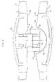
- FIG. 3is a cross sectional view of a first embodiment of the present invention, the first baseplate having an inwardly directed articulating surface having extending therefrom a mushroom-shaped pin element having a partial spherical element at the distal end thereof and a second baseplate having a circular recess within which seats the convex structure of the partial spherical element of the first baseplate.
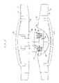
- FIG. 4is a cross-sectional view of a second embodiment of the present invention in which the pin element is slidably engaged in a central bore of the first baseplate and further includes a resilient member disposed between the first and second baseplates.
- FIG. 5is a cross-sectional view of a preferred embodiment of the present invention.
- FIG. 6is a cross-sectional view of a preferred embodiment of the present invention.
- each baseplate 10 , 30has an outwardly facing surface 12 , 32 .
- the two baseplates 10 , 30 used in the artificial discare disposed such that the outwardly facing surfaces 12 , 32 face away from one another.
- the two baseplates 10 , 30are to mate with the vertebral bodies so as to not rotate relative thereto, but rather to permit the spinal segments to bend relative to one another in manners that mimic the natural motion of the spinal segment. This motion is permitted by the performance of a ball and socket joint disposed between the secured baseplates 10 , 30 .
- the mating of the baseplates 10 , 30 to the vertebral bodies and the construction of the ball and socket jointare described below.
- each baseplate 10 , 30is a plate (preferably made of a metal or metal alloy, such as, for example, cobalt-chromium or titanium) having an overall shape that conforms to the overall shape of the respective endplate of the vertebral body with which it is to mate.
- each baseplate 10 , 30comprises a vertebral body contact element 80 , 82 (e.g., a convex mesh, preferably oval in shape) that is attached to the outwardly facing surface 12 , 32 of the baseplate 10 , 30 to provide a vertebral body contact surface.
- the mesh 80 , 82is secured at its perimeter to the outwardly facing surface 12 , 32 of the baseplate 10 , 30 .
- the mesh 80 , 82is domed in its initial undeflected conformation, but deflects as necessary during insertion of the artificial disc between vertebral bodies, and, once the artificial disc is seated between the vertebral bodies, deforms as necessary under anatomical loads to reshape itself to the concave surface of the vertebral endplate. This affords the baseplate 10 , 30 having the mesh 80 , 82 substantially superior gripping and holding strength upon initial implantation as compared with other artificial disc products.
- the mesh 80 , 82further provides an osteoconductive surface through which the bone may ultimately grow.
- the mesh 80 , 82is preferably comprised of titanium, but can also be formed from other metals and/or non-metals without departing from the scope of the invention.
- Each baseplate 10 , 30may further comprises at least a lateral ring (not shown) that is osteoconductive, which may be, for example, a sprayed deposition layer, or an adhesive applied beaded metal layer, or another suitable porous coating.
- This porous ringpermits the long-term ingrowth of vertebral bone into the baseplate 10 , 30 , thus permanently securing the prosthesis within the intervertebral space. It shall be understood that this porous layer may extend beneath the domed mesh 80 , 82 as well, but is more importantly applied to the lateral rim of the outwardly facing surface 12 , 32 of the baseplate 10 , 30 that seats directly against the vertebral body.
- the first baseplate 10includes an inwardly facing articulating surface 18 that includes a perimeter region 20 and a projection 22 protruding from the inwardly facing surface 18 .
- the projection 22preferably has a cylindrical or frustoconical cross section.
- the projection 22further includes an axial bore 26 that accepts a mushroom-shaped pin 50 (or rivet, plug, dowel, or screw).
- the second baseplate 30comprises an inwardly facing articulation surface 34 having a peripheral surface 36 and a curvate socket 38 , the socket 38 having a substantially constant radii concave articulation surface.
- Pin 50further comprises an elongated portion 52 and a head 54 , the head 54 having a convex arc having a substantially constant radius of curvature.
- the arc of head 54is such that the sphere it defines has a large radius, thereby minimizing point loading and the risk of fatigue failure.
- the projection 22 of baseplate 10is sized to have a diameter at least a portion of which is less than the diameter of the socket 38 .
- the projection 22preferably has a cross section that is cylindrical or frustoconical.
- the elongated portion 52 of mushroom-shaped pin 50is disposed in bore 26 of the baseplate 10 and the head 54 is nested in socket 38 .
- Pin 50is fixedly engaged by force fitting, welding or the like in bore 26 .
- Head 54is not captured in socket 38 .
- Baseplates 10 and 30are at no time connected to each other in the ball and socket joint of the present invention.
- a vertebral body contact element 80disposed over the outside surface 12 of the baseplate 10 .
- a vertebral body contact element 82on the baseplate 30 for purposes of symmetry.
- Such contact elements 80 and 82are preferably contoured to match the contour of the surface it contacts in the intervertebral space.
- pin 50is slidably engaged in bore 26 .
- a resilient annular member 60such as a resilient washer or the like is deployed over the projection 22 (which in this embodiment is preferably cylindrical) of the first baseplate 10 as a shock absorber, the resilient annular member 60 being sized and positioned such that it functions as a force restoring element (e.g., a spring) that provides axial cushioning to the device, by deflecting under a compressive load and restoring when the load is relieved.
- a force restoring elemente.g., a spring
- the elongated portion 52 of pin 50preferably has a continuous cylindrical cross section; however, the cross section may vary toward the distal end thereof, such as by gradually or abruptly thickening near the juncture of the elongated member 52 and the head 54 , to provide structural strength and/or to provide a different location for resilient member 60 .
- resilient member 60is a continuous collar comprising a spring having a cylindrical cross section. It is desirable, but not essential, to use a spring as the resilient member 60 because of the ability of a spring to hold its diameter when subjected to compressive force. In a most preferred embodiment resilient member 60 is retained in a retainer 62 .
- Retainer 62is formed of a resilient material such as but not limited to an elastomeric material.
- elongated member 52has a frustoconical section 56 adjacent proximal head 54 such that resilient member 60 and retainer 62 are firmly engageable in a seat formed between the frustoconical section 56 of elongated portion 52 and the end 28 of projection 22 .
- the spring comprising resilient member 60deforms outwardly such that its diameter increases.
- resilient member 60is an O-ring preferably formed of an elastomeric material.
- Retainer 62is a collar such as a split collar having formed thereon an exterior groove 64 to accommodate secure mounting of a resilient member 60 .
- elongated member 52has a frustoconical section 56 adjacent proximal head 54 such that resilient member 60 and retainer 62 are firmly engageable between the frustoconical section 56 of elongated portion 52 and the end 28 of projection 22 .
- the O-ring comprising resilient member 60deforms outwardly such that its diameter increases.
- the substantially constant radii articulation surfaces of the head 54 and socket 38are configured and sized to be nestable against one another and articulatable against one another, to enable adjacent vertebral bones (against which the baseplates 10 and 30 are respectively disposed in the intervertebral space) to articulate in flexion, extension, and lateral bending. More particularly, the artificial disc implant of the present invention is assembled by disposing the baseplates 10 and 30 such that the vertebral body contact surfaces 80 , 82 are directed away from one another, and the articulation surfaces (head 54 and socket 38 ) are nested against one another such that the concave arc of socket 38 accommodates the convex arc of head 54 .
Landscapes
- Health & Medical Sciences (AREA)
- Engineering & Computer Science (AREA)
- Biomedical Technology (AREA)
- Neurology (AREA)
- Orthopedic Medicine & Surgery (AREA)
- Cardiology (AREA)
- Oral & Maxillofacial Surgery (AREA)
- Transplantation (AREA)
- Heart & Thoracic Surgery (AREA)
- Vascular Medicine (AREA)
- Life Sciences & Earth Sciences (AREA)
- Animal Behavior & Ethology (AREA)
- General Health & Medical Sciences (AREA)
- Public Health (AREA)
- Veterinary Medicine (AREA)
- Prostheses (AREA)
- Surgical Instruments (AREA)
Abstract
Description
Claims (22)
Priority Applications (3)
| Application Number | Priority Date | Filing Date | Title |
|---|---|---|---|
| US11/056,064US7214244B2 (en) | 2004-02-19 | 2005-02-11 | Artificial intervertebral disc having an articulating joint |
| US11/708,813US7452380B2 (en) | 2004-02-19 | 2007-02-20 | Artificial intervertebral disc having an articulating joint |
| US12/228,435US8070814B2 (en) | 2004-02-19 | 2008-08-13 | Artificial intervertebral disc having an articulating joint |
Applications Claiming Priority (2)
| Application Number | Priority Date | Filing Date | Title |
|---|---|---|---|
| US54602704P | 2004-02-19 | 2004-02-19 | |
| US11/056,064US7214244B2 (en) | 2004-02-19 | 2005-02-11 | Artificial intervertebral disc having an articulating joint |
Related Child Applications (1)
| Application Number | Title | Priority Date | Filing Date |
|---|---|---|---|
| US11/708,813ContinuationUS7452380B2 (en) | 2004-02-19 | 2007-02-20 | Artificial intervertebral disc having an articulating joint |
Publications (2)
| Publication Number | Publication Date |
|---|---|
| US20050192670A1 US20050192670A1 (en) | 2005-09-01 |
| US7214244B2true US7214244B2 (en) | 2007-05-08 |
Family
ID=34886228
Family Applications (3)
| Application Number | Title | Priority Date | Filing Date |
|---|---|---|---|
| US11/056,064Expired - Fee RelatedUS7214244B2 (en) | 2004-02-19 | 2005-02-11 | Artificial intervertebral disc having an articulating joint |
| US11/708,813Expired - Fee RelatedUS7452380B2 (en) | 2004-02-19 | 2007-02-20 | Artificial intervertebral disc having an articulating joint |
| US12/228,435Expired - Fee RelatedUS8070814B2 (en) | 2004-02-19 | 2008-08-13 | Artificial intervertebral disc having an articulating joint |
Family Applications After (2)
| Application Number | Title | Priority Date | Filing Date |
|---|---|---|---|
| US11/708,813Expired - Fee RelatedUS7452380B2 (en) | 2004-02-19 | 2007-02-20 | Artificial intervertebral disc having an articulating joint |
| US12/228,435Expired - Fee RelatedUS8070814B2 (en) | 2004-02-19 | 2008-08-13 | Artificial intervertebral disc having an articulating joint |
Country Status (6)
| Country | Link |
|---|---|
| US (3) | US7214244B2 (en) |
| EP (1) | EP1740130A4 (en) |
| JP (2) | JP4554623B2 (en) |
| AU (2) | AU2005214915B2 (en) |
| CA (2) | CA2733450C (en) |
| WO (1) | WO2005079407A2 (en) |
Cited By (54)
| Publication number | Priority date | Publication date | Assignee | Title |
|---|---|---|---|---|
| US20040034422A1 (en)* | 2001-07-16 | 2004-02-19 | Errico Joseph P. | Intervertebral spacer device having a circumferentially buried wire mesh endplate attachment device |
| US20040153158A1 (en)* | 2001-07-16 | 2004-08-05 | Errico Joseph P. | Intervertebral spacer device having an angled perimeter for manipulation using a surgical tool |
| US20040167536A1 (en)* | 2001-07-16 | 2004-08-26 | Errico Joseph P. | Instrumentation for properly seating an artificial intervertebral disc in an intervertebral space |
| US20050187632A1 (en)* | 2004-02-20 | 2005-08-25 | Rafail Zubok | Artificial intervertebral disc having a bored semispherical bearing with a compression locking post and retaining caps |
| US20070123906A1 (en)* | 2001-07-16 | 2007-05-31 | Spinecore, Inc. | Inserter/impactor for implanting an artificial intervertebral disc |
| US20070150062A1 (en)* | 2004-02-19 | 2007-06-28 | Spinecore, Inc. | Artificial intervertebral disc having an articulating joint |
| US20070156243A1 (en)* | 2001-07-16 | 2007-07-05 | Spinecore, Inc. | Intervertebral spacer device having engagement hole pairs |
| US20070162139A1 (en)* | 2001-07-16 | 2007-07-12 | Ralph James D | Trial intervertebral distraction spacers |
| US20070168032A1 (en)* | 2006-01-13 | 2007-07-19 | Nabil L. Muhanna, M.D. | Flexible vertebral implant |
| US20070233107A1 (en)* | 2006-02-27 | 2007-10-04 | Zielinski Steven C | Method and apparatus for lateral reduction and fusion of the spine |
| US20080306597A1 (en)* | 2007-01-19 | 2008-12-11 | Pietro Filippo Adamo | Invertebral disc prosthesis for the cervical spine in the dog |
| US20090192618A1 (en)* | 2008-01-30 | 2009-07-30 | Zielinski Steven C | Artificial spinal disk |
| US20090270870A1 (en)* | 2008-04-24 | 2009-10-29 | Rafail Zubok | Dynamic distractor |
| US20090312765A1 (en)* | 2001-07-16 | 2009-12-17 | Spinecore, Inc. | Wedge Ramp Distractor for use in Implanting Artificial Intervertebral Discs |
| US20100262250A1 (en)* | 2006-11-07 | 2010-10-14 | Kellar Franz W | Prosthetic ball-and-socket joint |
| US7815648B2 (en) | 2004-06-02 | 2010-10-19 | Facet Solutions, Inc | Surgical measurement systems and methods |
| US20100324688A1 (en)* | 2009-06-18 | 2010-12-23 | Mekatronix | Intervertebral spinal disc prosthesis |
| US20110046744A1 (en)* | 2001-07-16 | 2011-02-24 | Spinecore, Inc. | Intervertebral spacer device having recessed notch pairs for manipulation using a surgical tool |
| US7905919B2 (en) | 2006-11-07 | 2011-03-15 | Biomedflex Llc | Prosthetic joint |
| US7914560B2 (en) | 2004-02-17 | 2011-03-29 | Gmedelaware 2 Llc | Spinal facet implant with spherical implant apposition surface and bone bed and methods of use |
| US7927375B2 (en) | 2008-09-12 | 2011-04-19 | Doty Keith L | Dynamic six-degrees-of-freedom intervertebral spinal disc prosthesis |
| US8002834B2 (en) | 2004-07-30 | 2011-08-23 | Spinalmotion, Inc. | Intervertebral prosthetic disc with metallic core |
| US8029574B2 (en) | 2006-11-07 | 2011-10-04 | Biomedflex Llc | Prosthetic knee joint |
| US8029568B2 (en) | 2001-10-18 | 2011-10-04 | Spinecore, Inc. | Intervertebral spacer device having a slotted partial circular domed arch strip spring |
| US8070823B2 (en) | 2006-11-07 | 2011-12-06 | Biomedflex Llc | Prosthetic ball-and-socket joint |
| US8083797B2 (en) | 2005-02-04 | 2011-12-27 | Spinalmotion, Inc. | Intervertebral prosthetic disc with shock absorption |
| US8090428B2 (en) | 2003-01-31 | 2012-01-03 | Spinalmotion, Inc. | Spinal midline indicator |
| US8092538B2 (en) | 2003-05-27 | 2012-01-10 | Spinalmotion, Inc. | Intervertebral prosthetic disc |
| US8092539B2 (en) | 2001-10-01 | 2012-01-10 | Spinecore, Inc. | Intervertebral spacer device having a belleville washer with concentric grooves |
| US8206418B2 (en) | 2007-01-10 | 2012-06-26 | Gmedelaware 2 Llc | System and method for facet joint replacement with detachable coupler |
| US8206447B2 (en) | 2004-08-06 | 2012-06-26 | Spinalmotion, Inc. | Methods and apparatus for intervertebral disc prosthesis insertion |
| US8206449B2 (en) | 2008-07-17 | 2012-06-26 | Spinalmotion, Inc. | Artificial intervertebral disc placement system |
| US8277505B1 (en) | 2011-06-10 | 2012-10-02 | Doty Keith L | Devices for providing up to six-degrees of motion having kinematically-linked components and methods of use |
| US8287598B1 (en) | 2011-12-05 | 2012-10-16 | TrueMotion Spine, Inc. | True spinal motion preserving, shock absorbing, intervertebral spinal disc prosthesis |
| US8308812B2 (en) | 2006-11-07 | 2012-11-13 | Biomedflex, Llc | Prosthetic joint assembly and joint member therefor |
| US8486147B2 (en) | 2006-04-12 | 2013-07-16 | Spinalmotion, Inc. | Posterior spinal device and method |
| US8506631B2 (en) | 2007-08-09 | 2013-08-13 | Spinalmotion, Inc. | Customized intervertebral prosthetic disc with shock absorption |
| US8512413B2 (en) | 2006-11-07 | 2013-08-20 | Biomedflex, Llc | Prosthetic knee joint |
| US8758441B2 (en) | 2007-10-22 | 2014-06-24 | Spinalmotion, Inc. | Vertebral body replacement and method for spanning a space formed upon removal of a vertebral body |
| US8764833B2 (en) | 2008-03-11 | 2014-07-01 | Spinalmotion, Inc. | Artificial intervertebral disc with lower height |
| US8777994B2 (en) | 2004-06-02 | 2014-07-15 | Gmedelaware 2 Llc | System and method for multiple level facet joint arthroplasty and fusion |
| US8845730B2 (en) | 2008-07-18 | 2014-09-30 | Simplify Medical, Inc. | Posterior prosthetic intervertebral disc |
| US9005307B2 (en) | 2006-11-07 | 2015-04-14 | Biomedflex, Llc | Prosthetic ball-and-socket joint |
| US9005306B2 (en) | 2006-11-07 | 2015-04-14 | Biomedflex, Llc | Medical Implants With Compliant Wear-Resistant Surfaces |
| US9011544B2 (en) | 2008-05-05 | 2015-04-21 | Simplify Medical, Inc. | Polyaryletherketone artificial intervertebral disc |
| US9034038B2 (en) | 2008-04-11 | 2015-05-19 | Spinalmotion, Inc. | Motion limiting insert for an artificial intervertebral disc |
| US9220603B2 (en) | 2008-07-02 | 2015-12-29 | Simplify Medical, Inc. | Limited motion prosthetic intervertebral disc |
| US9345583B2 (en) | 2011-12-20 | 2016-05-24 | Warsaw Orthopedic, Inc. | Spinal implant |
| US9402745B2 (en) | 2003-01-31 | 2016-08-02 | Simplify Medical, Inc. | Intervertebral prosthesis placement instrument |
| US9566157B2 (en) | 2006-11-07 | 2017-02-14 | Biomedflex, Llc | Three-member prosthetic joint |
| US9655741B2 (en) | 2003-05-27 | 2017-05-23 | Simplify Medical Pty Ltd | Prosthetic disc for intervertebral insertion |
| US9757247B2 (en) | 2012-10-01 | 2017-09-12 | DePuy Synthes Products, Inc. | Interbody fusion implant |
| US10258481B2 (en)* | 2013-03-15 | 2019-04-16 | Paradigm Spine, Llc | Modular, customizable spine stabilization system |
| US11096802B2 (en) | 2018-03-03 | 2021-08-24 | K2M, Inc. | Intervertebral trial with marker |
Families Citing this family (23)
| Publication number | Priority date | Publication date | Assignee | Title |
|---|---|---|---|---|
| US8388684B2 (en) | 2002-05-23 | 2013-03-05 | Pioneer Signal Technology, Inc. | Artificial disc device |
| AU2003226586A1 (en) | 2002-09-19 | 2004-04-08 | Malan De Villiers | Intervertebral prosthesis |
| US20090076614A1 (en)* | 2007-09-17 | 2009-03-19 | Spinalmotion, Inc. | Intervertebral Prosthetic Disc with Shock Absorption Core |
| WO2006104722A2 (en)* | 2005-03-24 | 2006-10-05 | Accelerated Innovation, Llc | Intervertebral disc replacement device |
| US8585764B2 (en) | 2005-07-06 | 2013-11-19 | Spontech Spine Intelligence Group Ag | Intervertebral disc prosthesis manufacturing method |
| US8152850B2 (en)* | 2005-07-06 | 2012-04-10 | Spontech Spine Intelligence Group Ag | Intervertebral disc prosthesis |
| US8016886B2 (en)* | 2006-07-18 | 2011-09-13 | Altus Partners, Llc | Intervertebral disc replacement device |
| US20080051900A1 (en)* | 2006-07-28 | 2008-02-28 | Spinalmotion, Inc. | Spinal Prosthesis with Offset Anchors |
| US8409213B2 (en)* | 2006-08-10 | 2013-04-02 | Pioneer Surgical Technology, Inc. | Insertion instrument for artificial discs |
| US8118872B2 (en) | 2006-08-10 | 2012-02-21 | Pioneer Surgical Technology, Inc. | System and methods for inserting a spinal disc device into an intervertebral space |
| US7976550B2 (en)* | 2006-08-10 | 2011-07-12 | Pioneer Surgical Technology | Insertion instrument for artificial discs |
| DE602006021239D1 (en)* | 2006-08-22 | 2011-05-19 | Synthes Gmbh | DEVICE FOR RIBBED TOTAL HEADSET |
| US8414616B2 (en) | 2006-09-12 | 2013-04-09 | Pioneer Surgical Technology, Inc. | Mounting devices for fixation devices and insertion instruments used therewith |
| US8372084B2 (en)* | 2006-09-22 | 2013-02-12 | Pioneer Surgical Technology, Inc. | System and methods for inserting a spinal disc device into an intervertebral space |
| US8715352B2 (en) | 2006-12-14 | 2014-05-06 | Depuy Spine, Inc. | Buckling disc replacement |
| WO2009094477A1 (en)* | 2008-01-25 | 2009-07-30 | Spinalmotion, Inc. | Compliant implantable prosthetic joint with preloaded spring |
| FR2929105B1 (en)* | 2008-03-25 | 2010-04-02 | Medicrea International | PROSTHESIS OF VERTEBRAL DISC, IN PARTICULAR FOR CERVICAL VERTEBRATES |
| EP2116211A1 (en)* | 2008-05-05 | 2009-11-11 | Christian Röbling | Intervertebral prosthesis |
| JP5663674B2 (en) | 2011-03-11 | 2015-02-04 | エフビーシー デバイス エーピーエス | Spine implant, pretreatment instrument and method of use |
| US8591591B2 (en) | 2011-05-25 | 2013-11-26 | Biomet Manufacturing, Llc | Spring base glenosphere |
| WO2019051260A1 (en) | 2017-09-08 | 2019-03-14 | Pioneer Surgical Technology, Inc. | Intervertebral implants, instruments, and methods |
| USD907771S1 (en) | 2017-10-09 | 2021-01-12 | Pioneer Surgical Technology, Inc. | Intervertebral implant |
| KR20240139110A (en)* | 2023-03-08 | 2024-09-23 | 재단법인 아산사회복지재단 | A multi-joint device |
Citations (17)
| Publication number | Priority date | Publication date | Assignee | Title |
|---|---|---|---|---|
| US4997432A (en) | 1988-03-23 | 1991-03-05 | Waldemar Link Gmbh & Co. | Surgical instrument set |
| US5314477A (en) | 1990-03-07 | 1994-05-24 | J.B.S. Limited Company | Prosthesis for intervertebral discs and instruments for implanting it |
| US5370697A (en) | 1992-04-21 | 1994-12-06 | Sulzer Medizinaltechnik Ag | Artificial intervertebral disk member |
| US5425773A (en) | 1992-01-06 | 1995-06-20 | Danek Medical, Inc. | Intervertebral disk arthroplasty device |
| US5507816A (en) | 1991-12-04 | 1996-04-16 | Customflex Limited | Spinal vertebrae implants |
| US5676702A (en) | 1994-12-16 | 1997-10-14 | Tornier S.A. | Elastic disc prosthesis |
| US5676701A (en) | 1993-01-14 | 1997-10-14 | Smith & Nephew, Inc. | Low wear artificial spinal disc |
| US5683465A (en) | 1996-03-18 | 1997-11-04 | Shinn; Gary Lee | Artificial intervertebral disk prosthesis |
| US5782832A (en) | 1996-10-01 | 1998-07-21 | Surgical Dynamics, Inc. | Spinal fusion implant and method of insertion thereof |
| US5893889A (en) | 1997-06-20 | 1999-04-13 | Harrington; Michael | Artificial disc |
| US5895428A (en) | 1996-11-01 | 1999-04-20 | Berry; Don | Load bearing spinal joint implant |
| US5899941A (en) | 1997-12-09 | 1999-05-04 | Chubu Bearing Kabushiki Kaisha | Artificial intervertebral disk |
| US5989291A (en) | 1998-02-26 | 1999-11-23 | Third Millennium Engineering, Llc | Intervertebral spacer device |
| US6368350B1 (en) | 1999-03-11 | 2002-04-09 | Sulzer Spine-Tech Inc. | Intervertebral disc prosthesis and method |
| US20020128714A1 (en) | 1999-06-04 | 2002-09-12 | Mark Manasas | Orthopedic implant and method of making metal articles |
| US20030014112A1 (en)* | 2001-07-16 | 2003-01-16 | Ralph James D. | Artificial intervertebral disc having a wave washer force restoring element |
| US20050251260A1 (en)* | 2002-08-15 | 2005-11-10 | David Gerber | Controlled artificial intervertebral disc implant |
Family Cites Families (11)
| Publication number | Priority date | Publication date | Assignee | Title |
|---|---|---|---|---|
| US5360430A (en)* | 1993-07-29 | 1994-11-01 | Lin Chih I | Intervertebral locking device |
| US6679915B1 (en)* | 1998-04-23 | 2004-01-20 | Sdgi Holdings, Inc. | Articulating spinal implant |
| US6019792A (en)* | 1998-04-23 | 2000-02-01 | Cauthen Research Group, Inc. | Articulating spinal implant |
| US6063121A (en)* | 1998-07-29 | 2000-05-16 | Xavier; Ravi | Vertebral body prosthesis |
| US6875235B2 (en)* | 1999-10-08 | 2005-04-05 | Bret A. Ferree | Prosthetic joints with contained compressible resilient members |
| CA2394663A1 (en)* | 2000-02-28 | 2001-09-07 | Sdgi Holdings, Inc. | Articulating spinal implant |
| US6989032B2 (en)* | 2001-07-16 | 2006-01-24 | Spinecore, Inc. | Artificial intervertebral disc |
| EP1646336B1 (en)* | 2003-07-22 | 2009-07-08 | Synthes GmbH | Intervertebral implant comprising dome-shaped joint surfaces |
| CN100566677C (en)* | 2003-07-22 | 2009-12-09 | 斯恩蒂斯有限公司 | The intraarticular prosthese |
| US20050038516A1 (en)* | 2003-08-14 | 2005-02-17 | Mark Spoonamore | Intervertebral disk prosthesis and method |
| US7214244B2 (en)* | 2004-02-19 | 2007-05-08 | Spinecore, Inc. | Artificial intervertebral disc having an articulating joint |
- 2005
- 2005-02-11USUS11/056,064patent/US7214244B2/ennot_activeExpired - Fee Related
- 2005-02-16CACA2733450Apatent/CA2733450C/ennot_activeExpired - Fee Related
- 2005-02-16EPEP05713608Apatent/EP1740130A4/ennot_activeWithdrawn
- 2005-02-16CACA2556364Apatent/CA2556364C/ennot_activeExpired - Fee Related
- 2005-02-16JPJP2006554171Apatent/JP4554623B2/ennot_activeExpired - Fee Related
- 2005-02-16AUAU2005214915Apatent/AU2005214915B2/ennot_activeCeased
- 2005-02-16WOPCT/US2005/004805patent/WO2005079407A2/ennot_activeApplication Discontinuation
- 2007
- 2007-02-20USUS11/708,813patent/US7452380B2/ennot_activeExpired - Fee Related
- 2008
- 2008-08-13USUS12/228,435patent/US8070814B2/ennot_activeExpired - Fee Related
- 2009
- 2009-09-11JPJP2009210682Apatent/JP4854775B2/ennot_activeExpired - Fee Related
- 2011
- 2011-02-18AUAU2011200724Apatent/AU2011200724B2/ennot_activeCeased
Patent Citations (17)
| Publication number | Priority date | Publication date | Assignee | Title |
|---|---|---|---|---|
| US4997432A (en) | 1988-03-23 | 1991-03-05 | Waldemar Link Gmbh & Co. | Surgical instrument set |
| US5314477A (en) | 1990-03-07 | 1994-05-24 | J.B.S. Limited Company | Prosthesis for intervertebral discs and instruments for implanting it |
| US5507816A (en) | 1991-12-04 | 1996-04-16 | Customflex Limited | Spinal vertebrae implants |
| US5425773A (en) | 1992-01-06 | 1995-06-20 | Danek Medical, Inc. | Intervertebral disk arthroplasty device |
| US5370697A (en) | 1992-04-21 | 1994-12-06 | Sulzer Medizinaltechnik Ag | Artificial intervertebral disk member |
| US5676701A (en) | 1993-01-14 | 1997-10-14 | Smith & Nephew, Inc. | Low wear artificial spinal disc |
| US5676702A (en) | 1994-12-16 | 1997-10-14 | Tornier S.A. | Elastic disc prosthesis |
| US5683465A (en) | 1996-03-18 | 1997-11-04 | Shinn; Gary Lee | Artificial intervertebral disk prosthesis |
| US5782832A (en) | 1996-10-01 | 1998-07-21 | Surgical Dynamics, Inc. | Spinal fusion implant and method of insertion thereof |
| US5895428A (en) | 1996-11-01 | 1999-04-20 | Berry; Don | Load bearing spinal joint implant |
| US5893889A (en) | 1997-06-20 | 1999-04-13 | Harrington; Michael | Artificial disc |
| US5899941A (en) | 1997-12-09 | 1999-05-04 | Chubu Bearing Kabushiki Kaisha | Artificial intervertebral disk |
| US5989291A (en) | 1998-02-26 | 1999-11-23 | Third Millennium Engineering, Llc | Intervertebral spacer device |
| US6368350B1 (en) | 1999-03-11 | 2002-04-09 | Sulzer Spine-Tech Inc. | Intervertebral disc prosthesis and method |
| US20020128714A1 (en) | 1999-06-04 | 2002-09-12 | Mark Manasas | Orthopedic implant and method of making metal articles |
| US20030014112A1 (en)* | 2001-07-16 | 2003-01-16 | Ralph James D. | Artificial intervertebral disc having a wave washer force restoring element |
| US20050251260A1 (en)* | 2002-08-15 | 2005-11-10 | David Gerber | Controlled artificial intervertebral disc implant |
Cited By (145)
| Publication number | Priority date | Publication date | Assignee | Title |
|---|---|---|---|---|
| US8940047B2 (en) | 2001-02-15 | 2015-01-27 | Spinecore, Inc. | Intervertebral spacer device having recessed notch pairs for manipulation using a surgical tool |
| US8858564B2 (en) | 2001-02-15 | 2014-10-14 | Spinecore, Inc. | Wedge plate inserter/impactor and related methods for use in implanting an artificial intervertebral disc |
| US9132020B2 (en) | 2001-07-16 | 2015-09-15 | Spinecore, Inc. | Wedge ramp distractor for use in implanting artificial intervertebral discs |
| US20040167536A1 (en)* | 2001-07-16 | 2004-08-26 | Errico Joseph P. | Instrumentation for properly seating an artificial intervertebral disc in an intervertebral space |
| US20070123906A1 (en)* | 2001-07-16 | 2007-05-31 | Spinecore, Inc. | Inserter/impactor for implanting an artificial intervertebral disc |
| US9700429B2 (en) | 2001-07-16 | 2017-07-11 | Spinecore, Inc. | Intervertebral spacer device having recessed notch pairs for manipulation using a surgical tool |
| US20070156243A1 (en)* | 2001-07-16 | 2007-07-05 | Spinecore, Inc. | Intervertebral spacer device having engagement hole pairs |
| US20070162139A1 (en)* | 2001-07-16 | 2007-07-12 | Ralph James D | Trial intervertebral distraction spacers |
| US8758358B2 (en) | 2001-07-16 | 2014-06-24 | Spinecore, Inc. | Instrumentation for repositioning and extraction an artificial intervertebral disc from an intervertebral space |
| US8216315B2 (en) | 2001-07-16 | 2012-07-10 | Spinecore, Inc. | Trial intervertebral distraction spacers |
| US20040153158A1 (en)* | 2001-07-16 | 2004-08-05 | Errico Joseph P. | Intervertebral spacer device having an angled perimeter for manipulation using a surgical tool |
| US9814596B2 (en) | 2001-07-16 | 2017-11-14 | Spinecore, Inc. | Method of orienting an intervertebral spacer device having recessed notch pairs by using a surgical tool |
| US8636804B2 (en) | 2001-07-16 | 2014-01-28 | Spinecore, Inc. | Instrumentation for properly seating an artificial intervertebral disc in an intervertebral space |
| US8608752B2 (en) | 2001-07-16 | 2013-12-17 | Spinecore, Inc. | Trial intervertebral distraction spacers |
| US8366775B2 (en) | 2001-07-16 | 2013-02-05 | Spinecore, Inc. | Intervertebral spacer device having an angled perimeter for manipulation using a surgical tool |
| US8357167B2 (en) | 2001-07-16 | 2013-01-22 | Spinecore, Inc. | Artificial intervertebral disc trials with baseplates having inward tool engagement holes |
| US20110046744A1 (en)* | 2001-07-16 | 2011-02-24 | Spinecore, Inc. | Intervertebral spacer device having recessed notch pairs for manipulation using a surgical tool |
| US8545564B2 (en) | 2001-07-16 | 2013-10-01 | Spinecore, Inc. | Intervertebral spacer device having an articulation member and housing |
| US20090312765A1 (en)* | 2001-07-16 | 2009-12-17 | Spinecore, Inc. | Wedge Ramp Distractor for use in Implanting Artificial Intervertebral Discs |
| US20090326542A9 (en)* | 2001-07-16 | 2009-12-31 | Errico Joseph P | Instrumentation for properly seating an artificial intervertebral disc in an intervertebral space |
| US8303659B2 (en) | 2001-07-16 | 2012-11-06 | Spinecore, Inc. | Intervertebral spacer device having engagement hole pairs |
| US20040034422A1 (en)* | 2001-07-16 | 2004-02-19 | Errico Joseph P. | Intervertebral spacer device having a circumferentially buried wire mesh endplate attachment device |
| US8092539B2 (en) | 2001-10-01 | 2012-01-10 | Spinecore, Inc. | Intervertebral spacer device having a belleville washer with concentric grooves |
| US8029568B2 (en) | 2001-10-18 | 2011-10-04 | Spinecore, Inc. | Intervertebral spacer device having a slotted partial circular domed arch strip spring |
| US10105131B2 (en) | 2003-01-31 | 2018-10-23 | Simplify Medical Pty Ltd | Intervertebral prosthesis placement instrument |
| US9402745B2 (en) | 2003-01-31 | 2016-08-02 | Simplify Medical, Inc. | Intervertebral prosthesis placement instrument |
| US8090428B2 (en) | 2003-01-31 | 2012-01-03 | Spinalmotion, Inc. | Spinal midline indicator |
| US10219911B2 (en) | 2003-05-27 | 2019-03-05 | Simplify Medical Pty Ltd | Prosthetic disc for intervertebral insertion |
| USRE46802E1 (en) | 2003-05-27 | 2018-04-24 | Simplify Medical Pty Limited | Intervertebral prosthetic disc with metallic core |
| US8444695B2 (en) | 2003-05-27 | 2013-05-21 | Spinalmotion, Inc. | Prosthetic disc for intervertebral insertion |
| US8845729B2 (en) | 2003-05-27 | 2014-09-30 | Simplify Medical, Inc. | Prosthetic disc for intervertebral insertion |
| US9655741B2 (en) | 2003-05-27 | 2017-05-23 | Simplify Medical Pty Ltd | Prosthetic disc for intervertebral insertion |
| US9788965B2 (en) | 2003-05-27 | 2017-10-17 | Simplify Medical Pty Ltd | Prosthetic disc for intervertebral insertion |
| US9107762B2 (en) | 2003-05-27 | 2015-08-18 | Spinalmotion, Inc. | Intervertebral prosthetic disc with metallic core |
| US10342671B2 (en) | 2003-05-27 | 2019-07-09 | Simplify Medical Pty Ltd | Intervertebral prosthetic disc |
| US10342670B2 (en) | 2003-05-27 | 2019-07-09 | Simplify Medical Pty Ltd | Intervertebral prosthetic disc |
| US10357376B2 (en) | 2003-05-27 | 2019-07-23 | Simplify Medical Pty Ltd | Intervertebral prosthetic disc |
| US8974533B2 (en) | 2003-05-27 | 2015-03-10 | Simplify Medical, Inc. | Prosthetic disc for intervertebral insertion |
| US8771356B2 (en) | 2003-05-27 | 2014-07-08 | Spinalmotion, Inc. | Intervertebral prosthetic disc |
| US10052211B2 (en) | 2003-05-27 | 2018-08-21 | Simplify Medical Pty Ltd. | Prosthetic disc for intervertebral insertion |
| US9439774B2 (en) | 2003-05-27 | 2016-09-13 | Simplify Medical Pty Ltd | Intervertebral prosthetic disc |
| US8454698B2 (en) | 2003-05-27 | 2013-06-04 | Spinalmotion, Inc. | Prosthetic disc for intervertebral insertion |
| US11771565B2 (en) | 2003-05-27 | 2023-10-03 | Simplify Medical Pty Ltd | Prosthetic disc for intervertebral insertion |
| US8092538B2 (en) | 2003-05-27 | 2012-01-10 | Spinalmotion, Inc. | Intervertebral prosthetic disc |
| US11376130B2 (en) | 2003-05-27 | 2022-07-05 | Simplify Medical Pty Ltd | Intervertebral prosthetic disc |
| US8906063B2 (en) | 2004-02-17 | 2014-12-09 | Gmedelaware 2 Llc | Spinal facet joint implant |
| US7998177B2 (en) | 2004-02-17 | 2011-08-16 | Gmedelaware 2 Llc | Linked bilateral spinal facet implants and methods of use |
| US7998178B2 (en) | 2004-02-17 | 2011-08-16 | Gmedelaware 2 Llc | Linked bilateral spinal facet implants and methods of use |
| US7914560B2 (en) | 2004-02-17 | 2011-03-29 | Gmedelaware 2 Llc | Spinal facet implant with spherical implant apposition surface and bone bed and methods of use |
| US20090048674A1 (en)* | 2004-02-19 | 2009-02-19 | Spinecore, Inc. | Artificial intervertebral disc having an articulating joint |
| US8070814B2 (en) | 2004-02-19 | 2011-12-06 | Spinecore, Inc. | Artificial intervertebral disc having an articulating joint |
| US7452380B2 (en)* | 2004-02-19 | 2008-11-18 | Spinecore, Inc. | Artificial intervertebral disc having an articulating joint |
| US20070150062A1 (en)* | 2004-02-19 | 2007-06-28 | Spinecore, Inc. | Artificial intervertebral disc having an articulating joint |
| US20050187632A1 (en)* | 2004-02-20 | 2005-08-25 | Rafail Zubok | Artificial intervertebral disc having a bored semispherical bearing with a compression locking post and retaining caps |
| US20080306594A1 (en)* | 2004-02-20 | 2008-12-11 | Spinecore, Inc. | Artificial intervertebral disc having a bored semispherical bearing with a compression locking post and retaining caps |
| US7393361B2 (en)* | 2004-02-20 | 2008-07-01 | Spinecore, Inc. | Artificial intervertebral disc having a bored semispherical bearing with a compression locking post and retaining caps |
| US8425609B2 (en) | 2004-02-20 | 2013-04-23 | Spinecore, Inc. | Artificial intervertebral disc having a bored semispherical bearing with a compression locking post and retaining caps |
| US8777994B2 (en) | 2004-06-02 | 2014-07-15 | Gmedelaware 2 Llc | System and method for multiple level facet joint arthroplasty and fusion |
| US7815648B2 (en) | 2004-06-02 | 2010-10-19 | Facet Solutions, Inc | Surgical measurement systems and methods |
| US8062371B2 (en) | 2004-07-30 | 2011-11-22 | Spinalmotion, Inc. | Intervertebral prosthetic disc with metallic core |
| US8002834B2 (en) | 2004-07-30 | 2011-08-23 | Spinalmotion, Inc. | Intervertebral prosthetic disc with metallic core |
| US8206447B2 (en) | 2004-08-06 | 2012-06-26 | Spinalmotion, Inc. | Methods and apparatus for intervertebral disc prosthesis insertion |
| US8974531B2 (en) | 2004-08-06 | 2015-03-10 | Simplify Medical, Inc. | Methods and apparatus for intervertebral disc prosthesis insertion |
| US10085853B2 (en) | 2004-08-06 | 2018-10-02 | Simplify Medical Pty Ltd | Methods and apparatus for intervertebral disc prosthesis insertion |
| US10888437B2 (en) | 2004-08-06 | 2021-01-12 | Simplify Medical Pty Ltd | Methods and apparatus for intervertebral disc prosthesis insertion |
| US10130494B2 (en) | 2004-08-06 | 2018-11-20 | Simplify Medical Pty Ltd. | Methods and apparatus for intervertebral disc prosthesis insertion |
| US9839532B2 (en) | 2004-08-06 | 2017-12-12 | Simplify Medical Pty Ltd | Methods and apparatus for intervertebral disc prosthesis insertion |
| US11857438B2 (en) | 2004-08-06 | 2024-01-02 | Simplify Medical Pty Ltd | Methods and apparatus for intervertebral disc prosthesis insertion |
| US9956091B2 (en) | 2004-08-06 | 2018-05-01 | Simplify Medical Pty Ltd | Methods and apparatus for intervertebral disc prosthesis insertion |
| US8398712B2 (en) | 2005-02-04 | 2013-03-19 | Spinalmotion, Inc. | Intervertebral prosthetic disc with shock absorption |
| US8083797B2 (en) | 2005-02-04 | 2011-12-27 | Spinalmotion, Inc. | Intervertebral prosthetic disc with shock absorption |
| US7815680B2 (en)* | 2006-01-13 | 2010-10-19 | Nabil L. Muhanna | Flexible vertebral implant |
| US20070168032A1 (en)* | 2006-01-13 | 2007-07-19 | Nabil L. Muhanna, M.D. | Flexible vertebral implant |
| US7914562B2 (en) | 2006-02-27 | 2011-03-29 | Zielinski Steven C | Method and apparatus for lateral reduction and fusion of the spine |
| US20070233107A1 (en)* | 2006-02-27 | 2007-10-04 | Zielinski Steven C | Method and apparatus for lateral reduction and fusion of the spine |
| USRE47796E1 (en) | 2006-04-12 | 2020-01-07 | Simplify Medical Pty Ltd | Posterior spinal device and method |
| US8486147B2 (en) | 2006-04-12 | 2013-07-16 | Spinalmotion, Inc. | Posterior spinal device and method |
| US8734519B2 (en) | 2006-04-12 | 2014-05-27 | Spinalmotion, Inc. | Posterior spinal device and method |
| US8801792B2 (en) | 2006-04-12 | 2014-08-12 | Spinalmotion, Inc. | Posterio spinal device and method |
| US8029574B2 (en) | 2006-11-07 | 2011-10-04 | Biomedflex Llc | Prosthetic knee joint |
| US8070823B2 (en) | 2006-11-07 | 2011-12-06 | Biomedflex Llc | Prosthetic ball-and-socket joint |
| US8308812B2 (en) | 2006-11-07 | 2012-11-13 | Biomedflex, Llc | Prosthetic joint assembly and joint member therefor |
| US20100262250A1 (en)* | 2006-11-07 | 2010-10-14 | Kellar Franz W | Prosthetic ball-and-socket joint |
| US9107754B2 (en) | 2006-11-07 | 2015-08-18 | Biomedflex, Llc | Prosthetic joint assembly and prosthetic joint member |
| US7905919B2 (en) | 2006-11-07 | 2011-03-15 | Biomedflex Llc | Prosthetic joint |
| US8512413B2 (en) | 2006-11-07 | 2013-08-20 | Biomedflex, Llc | Prosthetic knee joint |
| US7914580B2 (en) | 2006-11-07 | 2011-03-29 | Biomedflex Llc | Prosthetic ball-and-socket joint |
| US9005306B2 (en) | 2006-11-07 | 2015-04-14 | Biomedflex, Llc | Medical Implants With Compliant Wear-Resistant Surfaces |
| US9566157B2 (en) | 2006-11-07 | 2017-02-14 | Biomedflex, Llc | Three-member prosthetic joint |
| US9005307B2 (en) | 2006-11-07 | 2015-04-14 | Biomedflex, Llc | Prosthetic ball-and-socket joint |
| US8206418B2 (en) | 2007-01-10 | 2012-06-26 | Gmedelaware 2 Llc | System and method for facet joint replacement with detachable coupler |
| US8211147B2 (en) | 2007-01-10 | 2012-07-03 | Gmedelaware 2 Llc | System and method for facet joint replacement |
| US8252027B2 (en) | 2007-01-10 | 2012-08-28 | Gmedelaware 2 Llc | System and method for facet joint replacement |
| US8496707B2 (en)* | 2007-01-19 | 2013-07-30 | Pietro Filippo Adamo | Intervertebral disc prosthesis for the cervical spine in the dog |
| US20080306597A1 (en)* | 2007-01-19 | 2008-12-11 | Pietro Filippo Adamo | Invertebral disc prosthesis for the cervical spine in the dog |
| US9050144B2 (en) | 2007-04-17 | 2015-06-09 | Gmedelaware 2 Llc | System and method for implant anchorage with anti-rotation features |
| US8702759B2 (en) | 2007-04-17 | 2014-04-22 | Gmedelaware 2 Llc | System and method for bone anchorage |
| US10548739B2 (en) | 2007-08-09 | 2020-02-04 | Simplify Medical Pty Ltd | Customized intervertebral prosthetic disc with shock absorption |
| US9687355B2 (en) | 2007-08-09 | 2017-06-27 | Simplify Medical Pty Ltd | Customized intervertebral prosthetic disc with shock absorption |
| US8506631B2 (en) | 2007-08-09 | 2013-08-13 | Spinalmotion, Inc. | Customized intervertebral prosthetic disc with shock absorption |
| US9554917B2 (en) | 2007-08-09 | 2017-01-31 | Simplify Medical Pty Ltd | Customized intervertebral prosthetic disc with shock absorption |
| US12029656B2 (en) | 2007-08-09 | 2024-07-09 | Globus Medical Inc. | Customized intervertebral prosthetic disc with shock absorption |
| US9827108B2 (en) | 2007-08-09 | 2017-11-28 | Simplify Medical Pty Ltd | Customized intervertebral prosthetic disc with shock absorption |
| US11229526B2 (en) | 2007-08-09 | 2022-01-25 | Simplify Medical Pty Ltd. | Customized intervertebral prosthetic disc with shock absorption |
| USRE47470E1 (en) | 2007-10-22 | 2019-07-02 | Simplify Medical Pty Ltd | Vertebral body placement and method for spanning a space formed upon removal of a vertebral body |
| US8758441B2 (en) | 2007-10-22 | 2014-06-24 | Spinalmotion, Inc. | Vertebral body replacement and method for spanning a space formed upon removal of a vertebral body |
| US11364129B2 (en) | 2007-10-22 | 2022-06-21 | Simplify Medical Pty Ltd | Method and spacer device for spanning a space formed upon removal of an intervertebral disc |
| US8414649B1 (en)* | 2008-01-30 | 2013-04-09 | Steven C. Zielinski | Artificial spinal disk |
| US20110224794A1 (en)* | 2008-01-30 | 2011-09-15 | Zielinski Steven C | Artificial spinal disk |
| US8425605B2 (en)* | 2008-01-30 | 2013-04-23 | Steven C. Zielinski | Artificial spinal disk |
| US7909874B2 (en) | 2008-01-30 | 2011-03-22 | Zielinski Steven C | Artificial spinal disk |
| US20090192618A1 (en)* | 2008-01-30 | 2009-07-30 | Zielinski Steven C | Artificial spinal disk |
| US7909875B2 (en) | 2008-01-30 | 2011-03-22 | Zielinski Steven C | Artificial spinal disk |
| WO2009097293A1 (en)* | 2008-01-30 | 2009-08-06 | Zielinski Steven C | Artificial spinal disk |
| US9439775B2 (en) | 2008-03-11 | 2016-09-13 | Simplify Medical Pty Ltd | Artificial intervertebral disc with lower height |
| US8764833B2 (en) | 2008-03-11 | 2014-07-01 | Spinalmotion, Inc. | Artificial intervertebral disc with lower height |
| US9668878B2 (en) | 2008-03-11 | 2017-06-06 | Simplify Medical Pty Ltd | Artificial intervertebral disc with lower height |
| US10517733B2 (en) | 2008-03-11 | 2019-12-31 | Simplify Medical Pty Ltd | Artificial intervertebral disc with lower height |
| US11357633B2 (en) | 2008-03-11 | 2022-06-14 | Simplify Medical Pty Ltd | Artificial intervertebral disc with lower height |
| US9883945B2 (en) | 2008-03-11 | 2018-02-06 | Simplify Medical Pty Ltd | Artificial intervertebral disc with lower height |
| US12138171B2 (en) | 2008-03-11 | 2024-11-12 | Simplify Medical Pty Ltd. | Artificial intervertebral disc with lower height |
| US9034038B2 (en) | 2008-04-11 | 2015-05-19 | Spinalmotion, Inc. | Motion limiting insert for an artificial intervertebral disc |
| US20090270870A1 (en)* | 2008-04-24 | 2009-10-29 | Rafail Zubok | Dynamic distractor |
| US8147499B2 (en) | 2008-04-24 | 2012-04-03 | Spinecore, Inc. | Dynamic distractor |
| US11207190B2 (en) | 2008-05-05 | 2021-12-28 | Simplify Medical Pty Ltd | Polyaryletherketone artificial intervertebral disc |
| US9011544B2 (en) | 2008-05-05 | 2015-04-21 | Simplify Medical, Inc. | Polyaryletherketone artificial intervertebral disc |
| US9220603B2 (en) | 2008-07-02 | 2015-12-29 | Simplify Medical, Inc. | Limited motion prosthetic intervertebral disc |
| US8206449B2 (en) | 2008-07-17 | 2012-06-26 | Spinalmotion, Inc. | Artificial intervertebral disc placement system |
| US8636805B2 (en) | 2008-07-17 | 2014-01-28 | Spinalmotion, Inc. | Artificial intervertebral disc placement system |
| US8845730B2 (en) | 2008-07-18 | 2014-09-30 | Simplify Medical, Inc. | Posterior prosthetic intervertebral disc |
| US11986395B2 (en) | 2008-07-18 | 2024-05-21 | Simplify Medical Pty Ltd | Posterior prosthetic intervertebral disc |
| US11324605B2 (en) | 2008-07-18 | 2022-05-10 | Simplify Medical Pty Ltd | Posterior prosthetic intervertebral disc |
| US11413156B2 (en) | 2008-07-18 | 2022-08-16 | Simplify Medical Pty Ltd. | Posterior prosthetic intervertebral disc |
| US9351846B2 (en) | 2008-07-18 | 2016-05-31 | Simplify Medical, Inc. | Posterior prosthetic intervertebral disc |
| US7927375B2 (en) | 2008-09-12 | 2011-04-19 | Doty Keith L | Dynamic six-degrees-of-freedom intervertebral spinal disc prosthesis |
| US8202322B2 (en) | 2008-09-12 | 2012-06-19 | Doty Keith L | Dynamic six-degrees-of-freedom intervertebral spinal disc prosthesis |
| US20100324688A1 (en)* | 2009-06-18 | 2010-12-23 | Mekatronix | Intervertebral spinal disc prosthesis |
| US8226724B2 (en) | 2009-06-18 | 2012-07-24 | Doty Keith L | Intervertebral spinal disc prosthesis |
| US8277505B1 (en) | 2011-06-10 | 2012-10-02 | Doty Keith L | Devices for providing up to six-degrees of motion having kinematically-linked components and methods of use |
| US8287598B1 (en) | 2011-12-05 | 2012-10-16 | TrueMotion Spine, Inc. | True spinal motion preserving, shock absorbing, intervertebral spinal disc prosthesis |
| US9345583B2 (en) | 2011-12-20 | 2016-05-24 | Warsaw Orthopedic, Inc. | Spinal implant |
| US9757247B2 (en) | 2012-10-01 | 2017-09-12 | DePuy Synthes Products, Inc. | Interbody fusion implant |
| US11135068B2 (en) | 2012-10-01 | 2021-10-05 | DePuy Synthes Products, Inc. | Interbody fusion implant |
| US10258481B2 (en)* | 2013-03-15 | 2019-04-16 | Paradigm Spine, Llc | Modular, customizable spine stabilization system |
| US11096802B2 (en) | 2018-03-03 | 2021-08-24 | K2M, Inc. | Intervertebral trial with marker |
Also Published As
| Publication number | Publication date |
|---|---|
| AU2011200724A1 (en) | 2011-03-10 |
| JP4554623B2 (en) | 2010-09-29 |
| AU2011200724B2 (en) | 2012-05-03 |
| WO2005079407A3 (en) | 2006-11-23 |
| JP4854775B2 (en) | 2012-01-18 |
| US8070814B2 (en) | 2011-12-06 |
| US20090048674A1 (en) | 2009-02-19 |
| EP1740130A4 (en) | 2011-08-10 |
| AU2005214915A1 (en) | 2005-09-01 |
| US20050192670A1 (en) | 2005-09-01 |
| AU2005214915B2 (en) | 2010-11-25 |
| JP2007522879A (en) | 2007-08-16 |
| US20070150062A1 (en) | 2007-06-28 |
| EP1740130A2 (en) | 2007-01-10 |
| CA2556364A1 (en) | 2005-09-01 |
| CA2556364C (en) | 2011-05-17 |
| CA2733450A1 (en) | 2005-09-01 |
| WO2005079407A2 (en) | 2005-09-01 |
| JP2010017564A (en) | 2010-01-28 |
| US7452380B2 (en) | 2008-11-18 |
| CA2733450C (en) | 2013-01-08 |
Similar Documents
| Publication | Publication Date | Title |
|---|---|---|
| US7214244B2 (en) | Artificial intervertebral disc having an articulating joint | |
| US7604664B2 (en) | Spinal baseplates with ball joint coupling and a retaining member | |
| US7563285B2 (en) | Artificial intervertebral disc utilizing a ball joint coupling | |
| US7044970B2 (en) | Artificial intervertebral disc having limited rotation using a captured ball and socket joint with a solid ball, a compression locking post, and an interference ball bearing | |
| US20030069642A1 (en) | Artificial intervertebral disc having a flexible wire mesh vertebral body contact element | |
| US7393361B2 (en) | Artificial intervertebral disc having a bored semispherical bearing with a compression locking post and retaining caps | |
| US20030074066A1 (en) | Artificial intervertebral disc having limited rotation using a captured ball and socket joint with a solid ball, a retaining cap, and an interference pin | |
| WO2003032802A2 (en) | Intervertebral spacer device having an arched spring element |
Legal Events
| Date | Code | Title | Description |
|---|---|---|---|
| AS | Assignment | Owner name:SPINECORE, INC., NEW JERSEY Free format text:ASSIGNMENT OF ASSIGNORS INTEREST;ASSIGNORS:ZUBOK, RAFAIL;DUDASIK, MICHAEL W.;ERRICO, JOSEPH P.;REEL/FRAME:016208/0359;SIGNING DATES FROM 20050421 TO 20050427 | |
| STCF | Information on status: patent grant | Free format text:PATENTED CASE | |
| AS | Assignment | Owner name:SPINECORE, INC., NEW JERSEY Free format text:RE-RECORD TO REPLACE ASSIGNMENT DOCUMENT FILED UNDER REEL 016208, FRAME 0359;ASSIGNORS:ZUBOK, RAFAIL;DUDASIK, MICHAEL W.;ERRICO, JOSEPH P.;REEL/FRAME:023456/0927;SIGNING DATES FROM 20050421 TO 20050427 | |
| FPAY | Fee payment | Year of fee payment:4 | |
| FPAY | Fee payment | Year of fee payment:8 | |
| FEPP | Fee payment procedure | Free format text:MAINTENANCE FEE REMINDER MAILED (ORIGINAL EVENT CODE: REM.); ENTITY STATUS OF PATENT OWNER: LARGE ENTITY | |
| LAPS | Lapse for failure to pay maintenance fees | Free format text:PATENT EXPIRED FOR FAILURE TO PAY MAINTENANCE FEES (ORIGINAL EVENT CODE: EXP.); ENTITY STATUS OF PATENT OWNER: LARGE ENTITY | |
| STCH | Information on status: patent discontinuation | Free format text:PATENT EXPIRED DUE TO NONPAYMENT OF MAINTENANCE FEES UNDER 37 CFR 1.362 | |
| FP | Lapsed due to failure to pay maintenance fee | Effective date:20190508 | |
| AS | Assignment | Owner name:HOWMEDICA OTEONICS CORP., NEW JERSEY Free format text:MERGER;ASSIGNOR:SPINECORE, INC.;REEL/FRAME:053897/0621 Effective date:20190327 | |
| AS | Assignment | Owner name:HOWMEDICA OSTEONICS CORP., NEW JERSEY Free format text:CORRECTIVE ASSIGNMENT TO CORRECT THE ASSIGNEE NAME PREVIOUSLY RECORDED AT REEL: 053897 FRAME: 0621. ASSIGNOR(S) HEREBY CONFIRMS THE ASSIGNMENT;ASSIGNOR:SPINECORE, INC.;REEL/FRAME:053941/0753 Effective date:20190327 |