US7214225B2 - Connector - Google Patents
ConnectorDownload PDFInfo
- Publication number
- US7214225B2 US7214225B2US10/399,016US39901603AUS7214225B2US 7214225 B2US7214225 B2US 7214225B2US 39901603 AUS39901603 AUS 39901603AUS 7214225 B2US7214225 B2US 7214225B2
- Authority
- US
- United States
- Prior art keywords
- load bearing
- strands
- connector according
- filament
- apertures
- Prior art date
- Legal status (The legal status is an assumption and is not a legal conclusion. Google has not performed a legal analysis and makes no representation as to the accuracy of the status listed.)
- Expired - Lifetime, expires
Links
Images


Classifications
- A—HUMAN NECESSITIES
- A61—MEDICAL OR VETERINARY SCIENCE; HYGIENE
- A61B—DIAGNOSIS; SURGERY; IDENTIFICATION
- A61B17/00—Surgical instruments, devices or methods
- A61B17/56—Surgical instruments or methods for treatment of bones or joints; Devices specially adapted therefor
- A61B17/58—Surgical instruments or methods for treatment of bones or joints; Devices specially adapted therefor for osteosynthesis, e.g. bone plates, screws or setting implements
- A61B17/68—Internal fixation devices, including fasteners and spinal fixators, even if a part thereof projects from the skin
- A61B17/70—Spinal positioners or stabilisers, e.g. stabilisers comprising fluid filler in an implant
- A61B17/7055—Spinal positioners or stabilisers, e.g. stabilisers comprising fluid filler in an implant connected to sacrum, pelvis or skull
- A—HUMAN NECESSITIES
- A61—MEDICAL OR VETERINARY SCIENCE; HYGIENE
- A61B—DIAGNOSIS; SURGERY; IDENTIFICATION
- A61B17/00—Surgical instruments, devices or methods
- A61B17/56—Surgical instruments or methods for treatment of bones or joints; Devices specially adapted therefor
- A61B17/58—Surgical instruments or methods for treatment of bones or joints; Devices specially adapted therefor for osteosynthesis, e.g. bone plates, screws or setting implements
- A61B17/68—Internal fixation devices, including fasteners and spinal fixators, even if a part thereof projects from the skin
- A—HUMAN NECESSITIES
- A61—MEDICAL OR VETERINARY SCIENCE; HYGIENE
- A61F—FILTERS IMPLANTABLE INTO BLOOD VESSELS; PROSTHESES; DEVICES PROVIDING PATENCY TO, OR PREVENTING COLLAPSING OF, TUBULAR STRUCTURES OF THE BODY, e.g. STENTS; ORTHOPAEDIC, NURSING OR CONTRACEPTIVE DEVICES; FOMENTATION; TREATMENT OR PROTECTION OF EYES OR EARS; BANDAGES, DRESSINGS OR ABSORBENT PADS; FIRST-AID KITS
- A61F2/00—Filters implantable into blood vessels; Prostheses, i.e. artificial substitutes or replacements for parts of the body; Appliances for connecting them with the body; Devices providing patency to, or preventing collapsing of, tubular structures of the body, e.g. stents
- A61F2/02—Prostheses implantable into the body
- A61F2/08—Muscles; Tendons; Ligaments
- A—HUMAN NECESSITIES
- A61—MEDICAL OR VETERINARY SCIENCE; HYGIENE
- A61B—DIAGNOSIS; SURGERY; IDENTIFICATION
- A61B17/00—Surgical instruments, devices or methods
- A61B2017/00004—(bio)absorbable, (bio)resorbable or resorptive
- A—HUMAN NECESSITIES
- A61—MEDICAL OR VETERINARY SCIENCE; HYGIENE
- A61B—DIAGNOSIS; SURGERY; IDENTIFICATION
- A61B17/00—Surgical instruments, devices or methods
- A61B2017/00831—Material properties
- A61B2017/00867—Material properties shape memory effect
Definitions
- the present inventionconcerns a connector, in particular but not exclusively, a connector for use in surgery for connecting bones or bone parts to one another.
- the connectorWhen connecting bones or bone parts to one another using a connector, it is desirable for the connector to be capable of transmitting loads between the connected bone parts in a predetermined manner. This may be done to constrain separation between the bone parts by a predetermined amount and also constrain to a predetermined amount, the amount of torsional movement between the bone parts.
- a connectorcomprising at least one pair of apertures for receiving a fixation means, such as a screw or a toggle, a load bearing filament extending continuously along a predefined circuitous path which extends between and around each of the apertures of said pair of apertures, said load bearing filament extending around each aperture to define multiple aperture forming strands of said load bearing filaments, said aperture forming multiple strands of said load bearing filament being bound together around each aperture by binding filaments in order to constrain relative lateral movement between said aperture forming multiple strands and to define the shape of each aperture.
- a fixation meanssuch as a screw or a toggle
- FIG. 1is a schematic plan view of a connector according to a first embodiment of the present invention
- FIGS. 2 a to 2 care diagrammatic plan views of modifications to the first embodiment of the present invention.
- FIG. 3is a diagrammatic plan view of a connector according to a second embodiment of the present invention.
- FIG. 4diagrammatically illustrates a first example of formation of the second embodiment
- FIG. 5is a diagrammatic plan view of a third embodiment of the present invention.
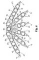
- FIG. 6is a diagrammatic plan view of a fourth embodiment of the present invention.
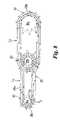
- FIG. 7is a diagrammatic illustration of connectors according to the present invention.
- FIG. 8is a second example of formation of the second embodiment.
- FIGS. 9 a to 9 dschematically illustrate laying of load bearing filaments to form multiple aperture forming strands.
- FIG. 1there is shown a connector 500 according to a first embodiment of the present invention.
- the connector 500includes a pair of apertures 18 a , 18 b and a load bearing filament 28 which follows a circuitous path which extends continuously around and between the apertures 18 a , 18 b .
- the connectoris attached to say a pair of bone parts by a fixation means, such as a screw or a toggle, located in the apertures 18 a , 18 b.
- the filament 28is preferably laid along said circuitous path for a plurality of complete circuits so as to define multiple strands 28 a , 28 b and 28 c .
- the multiple strands 28 adefine aperture connecting strands which extend in a direction parallel to the central axis C L joining the pair of apertures 18 a , 18 b ; strands 28 b define aperture forming strands which extend continuously around each aperture 18 a , 18 b ; and strands 28 c define aperture connecting strands which extend diagonally between the apertures 18 a , 18 b .
- the circuitous pathmay be varied in order to change the configuration of the connector 500 .
- the diagonal strands 28 care omitted such that the apertures 18 a , 18 b defined by the strands 28 b are connected by strands 28 a only.
- strands 28 aare omitted such that strands 28 b are connected by diagonal strands 28 c only.
- strands 28 bonly partially extend around the outer periphery of each aperture 18 a , 18 b.
- strands 28 amay also be included such that apertures 18 a , 18 b are connected by strands 28 a and 28 c ; or alternatively strands 28 a may be provided instead of strands 28 c.
- Binding filaments 30are provided which secure the strands 28 b together in order to constrain relative movement therebetween around each aperture 18 a , 18 b and also define the shape of each aperture 18 a , 18 b.
- the binding filaments 30thereby act to maintain integrity of each aperture 18 a , 18 b when a fixation means, such as a bone screw, is to be inserted through the aperture during attachment of the connector; the binding filaments 30 also act to maintain integrity of each aperture 18 a , 18 b when a tensile load is applied between the apertures 18 a , 18 b during use.
- a bone screwmay be inserted directly into apertures 18 a , 18 b without the need for an intermediary support such as a washer or collar.
- the binding filaments 30preferably extend around the entire periphery of each aperture 18 a , 18 b .
- the binding filaments 30extend about the outer periphery only of the apertures 18 a , 18 b .
- FIG. 3a further embodiment 600 is illustrated which comprises a first pair of apertures 18 a , 18 b linked with a second pair of apertures 18 b , 18 c .
- the apertures 18 a , 18 b ; 18 b , 18 c in each pairare connected to one another and defined by the load bearing filament 28 .
- the load bearing filament 28extends along a circuitous path between and around the apertures 18 a , 18 b and 18 c so as to connect them by multiple strands 28 a and/or 28 c and define them by strands 28 b .
- strands 28 aonly are provided.
- the circuitous path along which the load bearing filament 28 extendsenables the strands 28 a (and/or 28 c if provided) to be severed (as indicated by line S v ) between one pair of apertures 18 b , 18 c without adversely affecting the connection between the other pairs of apertures 18 a , 18 b .
- connection defined by the load bearing filament 28 between each pair of aperturesmay thus be considered as a chain defined by a series of chain links.
- FIG. 4An illustration of a circuitous path for the load bearing filament 28 in order to form the embodiment 600 is illustrated in FIG. 4 .
- the starting point of the pathis S p and the finishing point is F p .
- the load bearing yarn 28is laid along the path in the direction indicated by the arrows.
- the filamentis laid partially around the periphery of aperture 18 a , then extends to and completely around aperture 18 b then extends to and completely around aperture 18 c and then extends to and around aperture 18 b . It then extends to and completely round aperture 18 a .
- the load bearing yarn 28may be laid along this circuitous path several times in order to provide multiple strands 28 a.
- the multiple strands 28 bare secured together by binding filaments 30 after the load bearing filament 28 has been laid along the circuitous path.
- FIG. 8An alternative circuitous path for forming the embodiment 600 of FIG. 4 is illustrated in FIG. 8 .
- the filament 28is laid partially around the periphery of 18 a , then extends to and partially around the aperture 18 a .
- the filament 28initially follows a first substantially elliptical path which extends about apertures 18 a , 18 b .
- the filament 28is repeatedly laid along the first elliptical path for a predetermined number of times so as to define multiple strands 28 a and multiple strands 28 b . These collectively form a first chain link or loop L 1 .
- the filament 28After the filament 28 has been laid along the first elliptical path for said predetermined number of times, it is then laid along a second substantially elliptical path for another predetermined number of times; the second elliptical path extending around the next pair of apertures 18 b , 18 c . This forms a second chain link or loop L 2 .
- the filament 28After completing laying of the filament 28 around the second elliptical path for said predetermined number of times, the filament 28 is laid along side the strand of the first elliptical path which extend between apertures 18 a , 18 b . In this way, the same number of strands 28 a are laid inbetween each pair of apertures 18 a , 18 b ; and 18 b ; 18 c.
- the multiple aperture forming strands 28 bare secured together by binding filaments 30 which extend around each aperture (as shown in broken lines).
- the surgical connectorincludes multiple strands 28 a or 28 c , it is important that the tensile loads inbetween a pair of anchorage apertures be shared as equally as possible between the individual strands making up each multiple strand 28 a , and/or 28 c.
- the aperture interconnecting strands 28 a , and/or 28 cextend between a pair of apertures located on different planes which are also possibly of different orientation.
- the filament 28 when being laid along the circuitous pathis anchored at selected anchorage locations A L to a support backing sheet MS so that each individual strand extends between a series of anchorage locations spaced along its length and so is constrained thereby to follow a predefined path.
- the filamentis laid along the circuitous path by an embroidery machine having a base cloth support table movable in two dimensions in response to a patterning control for accurately positioning the base cloth relative to the sewing needle of the machine.
- the sewing needleis positioned on one side of the base cloth (referred to as the needle side of the base cloth) and when actuated penetrates through the base cloth to project from the opposite side of the base cloth (referred to as the looper side) in order to co-operate with a looper which supplies a looper thread to form a sewn stitch with thread supplied by the needle.
- the filament 28is supplied as the looper thread and so is laid on the looper side of the base cloth.
- the stitches formed between the filament 28 and needle threaddefine the anchorage locations along the length of the filament.
- the thread S T supplied to the sewing needleis preferably chosen so as to be much finer than the filament 28 such that the filament 28 remains substantially flat with the base cloth and is not pulled through toward the needle side of the base cloth. In this way the filament 28 remains substantially straight between each adjacent anchorage location defined by the stitches.
- the length of the filament 28 inbetween each adjacent stitchis therefore accurately predetermined.
- the heavier load bearing filament 28could be supplied by the needle and the finer thread S T be supplied by the looper.
- a minimal number of stitchesare formed along the filament 28 defining the aperture interconnecting strands 28 a and/or 28 c.
- the anchorage locationsWhen laying the filament 28 around an aperture, the anchorage locations are arranged to define a polygonal path (see FIG. 9 ).
- the number of anchorage locations A L and the spacing between adjacent locationsare chosen, bearing in mind the diametric size of the aperture to be formed and the bending capability of the filament 28 .
- the number of anchorage locations around an apertureis at least 3.
- the anchorage locations for adjacent individual strands 28 b around the aperture to be formedare positioned such that adjacent strands are nested in contact together in a predefined manner to resist lateral movement of the strands 28 b relative to one another when a tensile load is applied between a pair of adjacent apertures.
- binding filaments 30are sewn in a zig-zag manner around each aperture so as to enclose the strands 28 b.
- the strands 28 bremain in substantially the same position relative to one another as when they were laid and so each retains a predefined position around the aperture and so all individual strands making up the multiple aperture interconnecting strands 28 a and/or 28 c also retain their predefined length when placed under a tensile load inbetween adjacent apertures 18 and so the tensile load is substantially equally shared by the individual aperture interconnecting strands.
- the anchorage locations around A L the aperture to be formed for one strand 28 bare off-set from the anchorage locations of the neighbouring strand 28 b . This enables the strands 28 b to be closely arranged.
- the individual strands 28 bmay be arranged on top of one another such that a strand 128 b is seated within a groove 129 formed inbetween a pair of adjacent strands 228 b .
- a disciplined and predefined mannerit is possible to stack strands 28 b on top of one another in a disciplined and predefined manner to obtain a relatively large number of nested strands in a relatively small space which co-operate with one another to resist relative lateral movement.
- the load bearing filament 28is supported on a backing sheet MS which is preferably a mesh-like fabric formed from interconnected sewn stitches formed from yarns 20 .
- the backing sheet MSprimarily serves the purpose of retaining the load bearing filament 28 in a disciplined fashion for facilitating handling of the connector during implantation; it is not intended to accommodate tensile loadings between adjacent apertures. Accordingly, yarns 20 may be of a lighter weight than the filament 28 .
- the sewn stitchesare preferably formed using embroidery techniques which produce stitches above and below the load bearing filament 28 and so enwrap the load bearing filament 28 within the mesh-like fabric.
- the embroiderywill be performed on a base cloth which may be soluble so as to enable the base cloth to be dissolved away prior to implantation.
- the sewn stitches defining the mesh-like fabricthen constitute the backing sheet.
- the base clothmay be retained to define the backing sheet MS, this may be a knitted or woven fabric or a sheet of material such as plastics to which the load bearing filament 28 is attached, by for example suitable stitching.
- the backing sheet MSwhether formed by a sheet or a mesh-like fabric, or a knitted or woven fabric may be dissolvable so that once the backing sheet MS dissolves away it leaves apertures 18 a , 18 b connected solely by the load bearing filaments.
- the load bearing filamentsmay be laid along the circuitous path by passing around pegs 70 (illustrated in FIGS. 2 c ) with the strands 28 b then being subsequently secured by either stitching filaments 30 or wrapping filaments 30 around the strands 28 b (eg. using whipping techniques).
- the load bearing filament 28may be a textile yarn such as a polyester braided thread as used for sutures.
- the suture threadhas a diametric size between 0.2 to 0.5 mm, preferably about 0.35 mm.
- Other types of yarncould also be used, for example polypropylene, polyethylene, polyamide.
- the number of strands making up the multiple strands 28 z , 28 b and/or 28 cvary between 2 to 15; more preferably vary between 5 to 10.
- filamentary materialinstead of a textile yarn, other types of filamentary material may be used, e.g. wire of suitable metals such as a SMA (Shape Memory Alloy), aramid fibres, glass strands.
- SMAShape Memory Alloy
- the load bearing yarnmay be formed from a material which slowly dissolves after implantation. Suitable examples are polylactic acid or alginate fibres.
- any filament having the desired load bearing capabilities and flexibility for bending to lie along the desired circuitous pathmay be used.
- the yarn 20 and/or binding filament 30is a textile yarn, preferably a polyester braided thread.
- the yarn 20 and/or binding filament 30is preferably a suture braid thread having a diametric size between 0.1 to 0.2 mm, preferably about 0.15 mm.
- the connector of the inventionmay incorporate a pulling tail or cord P T which is longitudinally aligned with the row of apertures 18 a , 18 b and 18 c.
- a surgeonis able to secure the connector using aperture 18 a and then pull on the pulling tail P T in order to tension the connector before securing the connector using apertures 18 b and/or 18 c .
- the connectoris therefore pre-tensioned before final fixing.
- the pulling tail P Tis formed by a plurality of strands of load bearing yarn 28 which are laid so as to form a continuation of the chain formation. After installation the pulling tail P T may be cut away. Alternatively, the pulling tail may be used as a tie for providing additional anchorage of the connector.
- FIG. 5a connector 300 suitable for attachment to a vertebrae is illustrated.
- the load bearing filament 28in effect, creates a chain-link between apertures 18 a , 18 b and a pair of chain links between apertures 18 b , 18 c and 18 b , 18 d . This means that loads are spread evenly from aperture 18 b to both apertures 18 c , 18 d.
- Aperture 18 cis connected to three apertures 18 b , 18 d and 18 e by chain-links defined by strands 28 a such that loads are evenly distributed from aperture 18 c to apertures 18 b , 18 d and 18 e.
- FIG. 6A further example is illustrated in FIG. 6 which is a connector 400 suitable for use as an anterior spinal plate.
- the connector 400includes six arms 401 each formed by a series of apertures 18 interconnected by chain-links formed by the filaments 28 .
- the arms 401radiate from three main fixation apertures 18 a , 18 b and 18 c .
- These apertures 18 a , 18 b and 18 care attached to the LS vertebra of a patient and the arms 401 are attached to the sacrum. Due to the multiplicity of arms 401 and the plurality of apertures 18 they contain, it is possible to obtain good anchorage on the complex, three dimensional shape of the sacrum.
- each of the outer pair of arms 401is preferably interconnected to at least two of the apertures 18 a – 18 c in order to provide a desired spread of loadings.
- FIG. 7A specific use of connectors according to the present invention is illustrated in FIG. 7 wherein the connector is used as a spinal stabilisation device.
- the connector 800is shown as being connected to two vertebrae V 1 , V 2 by four pedicle screws 801 , 802 , 803 and 804 . It will be seen that the pairs of screws 801 , 802 and 803 , 804 located on opposite sides of the vertebrae are each linked by flexible connectors 807 and that they are also linked by transverse connectors 808 .
- the load bearing filament 28is laid along a predefined circuitous path to define adjacent individual strands 28 b extending about each aperture with aperture connecting strands 28 a and/or 28 c extending inbetween adjacent apertures.
- the individual strands 28 bare laid in a nested arrangement with individual strands held in the nested arrangement at anchorage locations connected to a backing sheet and by binding filaments 30 which bind all the individual strands 28 b together.
- Collectively securance of individual strands 28 b at said anchorage locations and binding all the strands 28 b together by filaments 30serve to restrain relative lateral movement between the individual strands 28 b when a tensile load is applied between a pair of adjacent apertures.
- the prime purpose of the anchorage locations and binding filament 30is to maintain the strands 28 b in position and not, themselves, to accommodate the tensile loadings inbetween adjacent apertures.
- the binding filament 30 and needle sewing thread used for forming the anchorage locationscan be of a lighter weight than the load bearing filament 28 . Since the binding filament 30 and sewing thread do not form a tensile load bearing function, the bulk size of the connector is, in the main, determined by the amount of load bearing filament 28 required.
- the backing sheetis provided primarily to retain the load bearing strands, in particular strands 28 a , 28 c in a disciplined manner for handling purposes during implantation, the flexibility of strands 28 a , 28 c is not impeded by the relatively lightweight backing sheet and thereby enables the load bearing strands 28 a , 28 c to bend/flex in a smooth manner inbetween adjacent bone anchorage locations.
Landscapes
- Health & Medical Sciences (AREA)
- Orthopedic Medicine & Surgery (AREA)
- Life Sciences & Earth Sciences (AREA)
- Surgery (AREA)
- Public Health (AREA)
- Veterinary Medicine (AREA)
- Engineering & Computer Science (AREA)
- Biomedical Technology (AREA)
- Heart & Thoracic Surgery (AREA)
- Animal Behavior & Ethology (AREA)
- General Health & Medical Sciences (AREA)
- Neurology (AREA)
- Molecular Biology (AREA)
- Medical Informatics (AREA)
- Nuclear Medicine, Radiotherapy & Molecular Imaging (AREA)
- Cardiology (AREA)
- Rheumatology (AREA)
- Oral & Maxillofacial Surgery (AREA)
- Rehabilitation Therapy (AREA)
- Vascular Medicine (AREA)
- Transplantation (AREA)
- Neurosurgery (AREA)
- Materials For Medical Uses (AREA)
- Connector Housings Or Holding Contact Members (AREA)
- Surgical Instruments (AREA)
- Prostheses (AREA)
- Mutual Connection Of Rods And Tubes (AREA)
- Mechanical Coupling Of Light Guides (AREA)
- Details Of Connecting Devices For Male And Female Coupling (AREA)
Abstract
Description
Claims (19)
Priority Applications (1)
| Application Number | Priority Date | Filing Date | Title |
|---|---|---|---|
| US11/801,263US20070208342A1 (en) | 2000-10-11 | 2007-05-08 | Connector |
Applications Claiming Priority (3)
| Application Number | Priority Date | Filing Date | Title |
|---|---|---|---|
| GB0024898.9 | 2000-10-11 | ||
| GBGB0024898.9AGB0024898D0 (en) | 2000-10-11 | 2000-10-11 | A connector |
| PCT/GB2001/004524WO2002030306A1 (en) | 2000-10-11 | 2001-10-11 | A connector |
Related Child Applications (1)
| Application Number | Title | Priority Date | Filing Date |
|---|---|---|---|
| US11/801,263DivisionUS20070208342A1 (en) | 2000-10-11 | 2007-05-08 | Connector |
Publications (2)
| Publication Number | Publication Date |
|---|---|
| US20040024403A1 US20040024403A1 (en) | 2004-02-05 |
| US7214225B2true US7214225B2 (en) | 2007-05-08 |
Family
ID=9901078
Family Applications (2)
| Application Number | Title | Priority Date | Filing Date |
|---|---|---|---|
| US10/399,016Expired - LifetimeUS7214225B2 (en) | 2000-10-11 | 2001-10-11 | Connector |
| US11/801,263AbandonedUS20070208342A1 (en) | 2000-10-11 | 2007-05-08 | Connector |
Family Applications After (1)
| Application Number | Title | Priority Date | Filing Date |
|---|---|---|---|
| US11/801,263AbandonedUS20070208342A1 (en) | 2000-10-11 | 2007-05-08 | Connector |
Country Status (10)
| Country | Link |
|---|---|
| US (2) | US7214225B2 (en) |
| EP (1) | EP1326547B1 (en) |
| JP (1) | JP4083007B2 (en) |
| KR (1) | KR100653242B1 (en) |
| AT (1) | ATE352261T1 (en) |
| AU (1) | AU2001294001A1 (en) |
| DE (1) | DE60126299T2 (en) |
| GB (1) | GB0024898D0 (en) |
| WO (1) | WO2002030306A1 (en) |
| ZA (1) | ZA200303606B (en) |
Cited By (22)
| Publication number | Priority date | Publication date | Assignee | Title |
|---|---|---|---|---|
| US20040078089A1 (en)* | 2000-10-11 | 2004-04-22 | Julian Ellis | Textile prosthesis |
| US20070208342A1 (en)* | 2000-10-11 | 2007-09-06 | Julian Ellis | Connector |
| US20080173223A1 (en)* | 2007-01-22 | 2008-07-24 | Nuvasive, Inc. | 3-dimensional embroidery structures via tension shaping |
| US20080178786A1 (en)* | 2007-01-31 | 2008-07-31 | Nuvasive, Inc. | Using zigzags to create three-dimensional embroidered structures |
| US20080188936A1 (en)* | 2007-02-02 | 2008-08-07 | Tornier, Inc. | System and method for repairing tendons and ligaments |
| US20080306593A1 (en)* | 2004-03-26 | 2008-12-11 | Mcleod Alan Rory Mor | Prosthetic Spinal Disc |
| US20090138082A1 (en)* | 2007-11-19 | 2009-05-28 | Nuvasive, Inc. | Textile-Based Plate Implant and Related Methods |
| US20100089297A1 (en)* | 2006-09-25 | 2010-04-15 | Peter Butcher | Embroidery Using Soluble Thread |
| US7713463B1 (en) | 2007-11-13 | 2010-05-11 | Nuvasive, Inc. | Method of manufacturing embroidered surgical implants |
| US8282681B2 (en) | 2007-08-13 | 2012-10-09 | Nuvasive, Inc. | Bioresorbable spinal implant and related methods |
| US8328807B2 (en) | 2008-07-09 | 2012-12-11 | Icon Orthopaedic Concepts, Llc | Ankle arthrodesis nail and outrigger assembly |
| US8377135B1 (en) | 2008-03-31 | 2013-02-19 | Nuvasive, Inc. | Textile-based surgical implant and related methods |
| US8414584B2 (en) | 2008-07-09 | 2013-04-09 | Icon Orthopaedic Concepts, Llc | Ankle arthrodesis nail and outrigger assembly |
| US10321833B2 (en) | 2016-10-05 | 2019-06-18 | Innovative Surgical Solutions. | Neural locating method |
| US10376209B2 (en) | 2013-09-20 | 2019-08-13 | Innovative Surgical Solutions, Llc | Neural locating method |
| US10376208B2 (en) | 2013-09-20 | 2019-08-13 | Innovative Surgical Solutions, Llc | Nerve mapping system |
| US10449002B2 (en) | 2013-09-20 | 2019-10-22 | Innovative Surgical Solutions, Llc | Method of mapping a nerve |
| US10478096B2 (en) | 2013-08-13 | 2019-11-19 | Innovative Surgical Solutions. | Neural event detection |
| US10478097B2 (en) | 2013-08-13 | 2019-11-19 | Innovative Surgical Solutions | Neural event detection |
| US10870002B2 (en) | 2018-10-12 | 2020-12-22 | DePuy Synthes Products, Inc. | Neuromuscular sensing device with multi-sensor array |
| US10869616B2 (en) | 2018-06-01 | 2020-12-22 | DePuy Synthes Products, Inc. | Neural event detection |
| US11399777B2 (en) | 2019-09-27 | 2022-08-02 | DePuy Synthes Products, Inc. | Intraoperative neural monitoring system and method |
Families Citing this family (3)
| Publication number | Priority date | Publication date | Assignee | Title |
|---|---|---|---|---|
| US8826328B2 (en)* | 2004-11-12 | 2014-09-02 | Opentv, Inc. | Communicating primary content streams and secondary content streams including targeted advertising to a remote unit |
| WO2014098779A2 (en)* | 2012-12-21 | 2014-06-26 | DEMIRBOGA, Muhittin | Artificial ligament and tendon repair system |
| US10085830B2 (en) | 2016-05-13 | 2018-10-02 | Medos International Sarl | Device, system, and method for delivery of a tissue fixation device |
Citations (6)
| Publication number | Priority date | Publication date | Assignee | Title |
|---|---|---|---|---|
| US5108397A (en)* | 1990-04-19 | 1992-04-28 | Joseph White | Method and apparatus for stabilization of pelvic fractures |
| FR2710520A1 (en)* | 1993-09-28 | 1995-04-07 | Vidal Jean Jacques | Method for forming a rigid and flexible textile structure which has high resistance to traction and buckling and has good compression behaviour |
| US6033429A (en)* | 1998-01-13 | 2000-03-07 | Cardiac Assist Technologies, Inc. | System, apparatus and method for closing severed bone or tissue of a patient |
| US20010027319A1 (en)* | 2000-02-25 | 2001-10-04 | Ferree Bret A. | Cross-coupled vertebral stabilizers including cam-operated cable connectors |
| US6368326B1 (en)* | 1998-09-28 | 2002-04-09 | Daos Limited | Internal cord fixation device |
| WO2002030324A1 (en) | 2000-10-11 | 2002-04-18 | Ellis Developments Limited | A textile prosthesis |
Family Cites Families (18)
| Publication number | Priority date | Publication date | Assignee | Title |
|---|---|---|---|---|
| FI78393C (en)* | 1982-09-10 | 1989-08-10 | Gore & Ass | SYNTHETIC PROCESSES FOR ERSAETTING ELLER REPARATION AV LIGAMENT ELLER SENOR. |
| ZA875425B (en)* | 1986-07-23 | 1988-04-27 | Gore & Ass | Mechanical ligament |
| GB8622563D0 (en)* | 1986-09-19 | 1986-10-22 | Amis A A | Artificial ligaments |
| US4946377A (en)* | 1989-11-06 | 1990-08-07 | W. L. Gore & Associates, Inc. | Tissue repair device |
| EP0437174B1 (en)* | 1990-01-08 | 1993-12-22 | SULZER Medizinaltechnik AG | Artificial ligament and/or tendon replacement implant |
| GB9217578D0 (en)* | 1992-08-19 | 1992-09-30 | Surgicarft Ltd | Surgical implants,etc |
| FR2696338B1 (en)* | 1992-10-07 | 1997-10-17 | Max Perrin | ARTIFICIAL LIGAMENT AND ITS PRESENTATION MODE. |
| US5456722A (en)* | 1993-01-06 | 1995-10-10 | Smith & Nephew Richards Inc. | Load bearing polymeric cable |
| GB9306737D0 (en)* | 1993-03-31 | 1993-05-26 | Surgicarft Ltd | Ligament augmentation device |
| US5454812A (en)* | 1993-11-12 | 1995-10-03 | Lin; Chih-I | Spinal clamping device having multiple distance adjusting strands |
| GB9510624D0 (en)* | 1995-05-25 | 1995-07-19 | Ellis Dev Ltd | Textile surgical implants |
| US6436099B1 (en)* | 1999-04-23 | 2002-08-20 | Sdgi Holdings, Inc. | Adjustable spinal tether |
| US6592625B2 (en)* | 1999-10-20 | 2003-07-15 | Anulex Technologies, Inc. | Spinal disc annulus reconstruction method and spinal disc annulus stent |
| US6248106B1 (en)* | 2000-02-25 | 2001-06-19 | Bret Ferree | Cross-coupled vertebral stabilizers |
| US6620196B1 (en)* | 2000-08-30 | 2003-09-16 | Sdgi Holdings, Inc. | Intervertebral disc nucleus implants and methods |
| GB0024898D0 (en)* | 2000-10-11 | 2000-11-22 | Ellis Dev Ltd | A connector |
| CA2429149C (en)* | 2000-12-15 | 2010-08-24 | Spineology, Inc. | Annulus-reinforcing band |
| US7176344B2 (en)* | 2002-09-06 | 2007-02-13 | Sca Hygiene Products Ab | Sensoring absorbing article |
- 2000
- 2000-10-11GBGBGB0024898.9Apatent/GB0024898D0/ennot_activeCeased
- 2001
- 2001-10-11JPJP2002533755Apatent/JP4083007B2/ennot_activeExpired - Lifetime
- 2001-10-11WOPCT/GB2001/004524patent/WO2002030306A1/enactiveIP Right Grant
- 2001-10-11KRKR1020037005180Apatent/KR100653242B1/ennot_activeExpired - Fee Related
- 2001-10-11EPEP01974486Apatent/EP1326547B1/ennot_activeExpired - Lifetime
- 2001-10-11DEDE60126299Tpatent/DE60126299T2/ennot_activeExpired - Lifetime
- 2001-10-11ATAT01974486Tpatent/ATE352261T1/ennot_activeIP Right Cessation
- 2001-10-11AUAU2001294001Apatent/AU2001294001A1/ennot_activeAbandoned
- 2001-10-11USUS10/399,016patent/US7214225B2/ennot_activeExpired - Lifetime
- 2003
- 2003-05-09ZAZA200303606Apatent/ZA200303606B/enunknown
- 2007
- 2007-05-08USUS11/801,263patent/US20070208342A1/ennot_activeAbandoned
Patent Citations (6)
| Publication number | Priority date | Publication date | Assignee | Title |
|---|---|---|---|---|
| US5108397A (en)* | 1990-04-19 | 1992-04-28 | Joseph White | Method and apparatus for stabilization of pelvic fractures |
| FR2710520A1 (en)* | 1993-09-28 | 1995-04-07 | Vidal Jean Jacques | Method for forming a rigid and flexible textile structure which has high resistance to traction and buckling and has good compression behaviour |
| US6033429A (en)* | 1998-01-13 | 2000-03-07 | Cardiac Assist Technologies, Inc. | System, apparatus and method for closing severed bone or tissue of a patient |
| US6368326B1 (en)* | 1998-09-28 | 2002-04-09 | Daos Limited | Internal cord fixation device |
| US20010027319A1 (en)* | 2000-02-25 | 2001-10-04 | Ferree Bret A. | Cross-coupled vertebral stabilizers including cam-operated cable connectors |
| WO2002030324A1 (en) | 2000-10-11 | 2002-04-18 | Ellis Developments Limited | A textile prosthesis |
Cited By (36)
| Publication number | Priority date | Publication date | Assignee | Title |
|---|---|---|---|---|
| US7828855B2 (en)* | 2000-10-11 | 2010-11-09 | Nuvasive, Inc. | Textile prosthesis |
| US20070208342A1 (en)* | 2000-10-11 | 2007-09-06 | Julian Ellis | Connector |
| US7338531B2 (en)* | 2000-10-11 | 2008-03-04 | Julian Ellis | Textile prosthesis |
| US20040078089A1 (en)* | 2000-10-11 | 2004-04-22 | Julian Ellis | Textile prosthesis |
| US20080234835A1 (en)* | 2000-10-11 | 2008-09-25 | Julian Ellis | Textile Prosthesis |
| US20110054610A1 (en)* | 2000-10-11 | 2011-03-03 | Julian Ellis | Textile Prosthesis |
| US20080306593A1 (en)* | 2004-03-26 | 2008-12-11 | Mcleod Alan Rory Mor | Prosthetic Spinal Disc |
| US8074591B2 (en) | 2006-09-25 | 2011-12-13 | Nuvasive, Inc. | Embroidery using soluble thread |
| US20100089297A1 (en)* | 2006-09-25 | 2010-04-15 | Peter Butcher | Embroidery Using Soluble Thread |
| US20080173223A1 (en)* | 2007-01-22 | 2008-07-24 | Nuvasive, Inc. | 3-dimensional embroidery structures via tension shaping |
| US7942104B2 (en)* | 2007-01-22 | 2011-05-17 | Nuvasive, Inc. | 3-dimensional embroidery structures via tension shaping |
| US20080178786A1 (en)* | 2007-01-31 | 2008-07-31 | Nuvasive, Inc. | Using zigzags to create three-dimensional embroidered structures |
| US7946236B2 (en)* | 2007-01-31 | 2011-05-24 | Nuvasive, Inc. | Using zigzags to create three-dimensional embroidered structures |
| US20080188936A1 (en)* | 2007-02-02 | 2008-08-07 | Tornier, Inc. | System and method for repairing tendons and ligaments |
| US8282681B2 (en) | 2007-08-13 | 2012-10-09 | Nuvasive, Inc. | Bioresorbable spinal implant and related methods |
| US7713463B1 (en) | 2007-11-13 | 2010-05-11 | Nuvasive, Inc. | Method of manufacturing embroidered surgical implants |
| US8591584B2 (en) | 2007-11-19 | 2013-11-26 | Nuvasive, Inc. | Textile-based plate implant and related methods |
| US20090138082A1 (en)* | 2007-11-19 | 2009-05-28 | Nuvasive, Inc. | Textile-Based Plate Implant and Related Methods |
| US8377135B1 (en) | 2008-03-31 | 2013-02-19 | Nuvasive, Inc. | Textile-based surgical implant and related methods |
| US8328807B2 (en) | 2008-07-09 | 2012-12-11 | Icon Orthopaedic Concepts, Llc | Ankle arthrodesis nail and outrigger assembly |
| US9226783B2 (en) | 2008-07-09 | 2016-01-05 | Icon Orthopaedic Concepts, Llc | Ankle arthrodesis nail and outrigger assembly |
| US8414584B2 (en) | 2008-07-09 | 2013-04-09 | Icon Orthopaedic Concepts, Llc | Ankle arthrodesis nail and outrigger assembly |
| EP2189123A1 (en) | 2008-11-19 | 2010-05-26 | Nuvasive, Inc. | Textile-based plate implant and related methods |
| US10478096B2 (en) | 2013-08-13 | 2019-11-19 | Innovative Surgical Solutions. | Neural event detection |
| US10478097B2 (en) | 2013-08-13 | 2019-11-19 | Innovative Surgical Solutions | Neural event detection |
| US10376209B2 (en) | 2013-09-20 | 2019-08-13 | Innovative Surgical Solutions, Llc | Neural locating method |
| US10449002B2 (en) | 2013-09-20 | 2019-10-22 | Innovative Surgical Solutions, Llc | Method of mapping a nerve |
| US10376208B2 (en) | 2013-09-20 | 2019-08-13 | Innovative Surgical Solutions, Llc | Nerve mapping system |
| US10321833B2 (en) | 2016-10-05 | 2019-06-18 | Innovative Surgical Solutions. | Neural locating method |
| US11311222B2 (en) | 2016-10-05 | 2022-04-26 | Innovative Surgical Solutions | Neural locating system |
| US12109042B2 (en) | 2016-10-05 | 2024-10-08 | Innovative Surgical Solutions, Llc | Neural locating system and method |
| US10869616B2 (en) | 2018-06-01 | 2020-12-22 | DePuy Synthes Products, Inc. | Neural event detection |
| US10870002B2 (en) | 2018-10-12 | 2020-12-22 | DePuy Synthes Products, Inc. | Neuromuscular sensing device with multi-sensor array |
| US12090320B2 (en) | 2018-10-12 | 2024-09-17 | DePuy Synthes Products, Inc. | Neuromuscular sensing device with multi-sensor array |
| US11399777B2 (en) | 2019-09-27 | 2022-08-02 | DePuy Synthes Products, Inc. | Intraoperative neural monitoring system and method |
| US12303301B2 (en) | 2019-09-27 | 2025-05-20 | DePuy Synthes Products, Inc. | Intraoperative neural monitoring system and method |
Also Published As
| Publication number | Publication date |
|---|---|
| EP1326547A1 (en) | 2003-07-16 |
| WO2002030306A1 (en) | 2002-04-18 |
| KR20030076570A (en) | 2003-09-26 |
| AU2001294001A1 (en) | 2002-04-22 |
| EP1326547B1 (en) | 2007-01-24 |
| JP4083007B2 (en) | 2008-04-30 |
| GB0024898D0 (en) | 2000-11-22 |
| KR100653242B1 (en) | 2006-12-06 |
| DE60126299T2 (en) | 2007-05-31 |
| JP2004510538A (en) | 2004-04-08 |
| US20040024403A1 (en) | 2004-02-05 |
| US20070208342A1 (en) | 2007-09-06 |
| DE60126299D1 (en) | 2007-03-15 |
| ZA200303606B (en) | 2004-03-30 |
| ATE352261T1 (en) | 2007-02-15 |
Similar Documents
| Publication | Publication Date | Title |
|---|---|---|
| US7214225B2 (en) | Connector | |
| US7338531B2 (en) | Textile prosthesis | |
| JP6792929B2 (en) | Suture anchor with suture filament and suture tape | |
| US8074591B2 (en) | Embroidery using soluble thread | |
| EP2739242B1 (en) | Connective tissue repair pad | |
| EP2739241B1 (en) | Connective tissue repair | |
| JP2013144009A (en) | Suture for suture fixation of medical instrument, method of using the same and medical instrument suture-fixed using the suture | |
| JP7381627B2 (en) | Multi-density full suture anchor | |
| US11844507B2 (en) | Flat-type sleeve anchor | |
| US20240382189A1 (en) | Fixed swaged soft suture methods & apparatus | |
| WO2025193994A1 (en) | Suspensory fixation device |
Legal Events
| Date | Code | Title | Description |
|---|---|---|---|
| STCF | Information on status: patent grant | Free format text:PATENTED CASE | |
| FEPP | Fee payment procedure | Free format text:PAT HOLDER NO LONGER CLAIMS SMALL ENTITY STATUS, ENTITY STATUS SET TO UNDISCOUNTED (ORIGINAL EVENT CODE: STOL); ENTITY STATUS OF PATENT OWNER: LARGE ENTITY | |
| REFU | Refund | Free format text:REFUND - SURCHARGE, PETITION TO ACCEPT PYMT AFTER EXP, UNINTENTIONAL (ORIGINAL EVENT CODE: R2551); ENTITY STATUS OF PATENT OWNER: LARGE ENTITY | |
| FPAY | Fee payment | Year of fee payment:4 | |
| FPAY | Fee payment | Year of fee payment:8 | |
| AS | Assignment | Owner name:BANK OF AMERICA, N.A., AS ADMINISTRATIVE AGENT, CALIFORNIA Free format text:NOTICE OF GRANT OF SECURITY INTEREST IN PATENTS;ASSIGNORS:NUVASIVE, INC.;IMPULSE MONITORING, INC.;REEL/FRAME:040634/0404 Effective date:20160208 Owner name:BANK OF AMERICA, N.A., AS ADMINISTRATIVE AGENT, CA Free format text:NOTICE OF GRANT OF SECURITY INTEREST IN PATENTS;ASSIGNORS:NUVASIVE, INC.;IMPULSE MONITORING, INC.;REEL/FRAME:040634/0404 Effective date:20160208 | |
| AS | Assignment | Owner name:BANK OF AMERICA, N.A., AS ADMINISTRATIVE AGENT, TE Free format text:NOTICE OF GRANT OF SECURITY INTEREST IN PATENTS;ASSIGNORS:NUVASIVE, INC.;BIOTRONIC NATIONAL, LLC;NUVASIVE CLINICAL SERVICES MONITORING, INC.;AND OTHERS;REEL/FRAME:042490/0236 Effective date:20170425 Owner name:BANK OF AMERICA, N.A., AS ADMINISTRATIVE AGENT, TEXAS Free format text:NOTICE OF GRANT OF SECURITY INTEREST IN PATENTS;ASSIGNORS:NUVASIVE, INC.;BIOTRONIC NATIONAL, LLC;NUVASIVE CLINICAL SERVICES MONITORING, INC.;AND OTHERS;REEL/FRAME:042490/0236 Effective date:20170425 | |
| MAFP | Maintenance fee payment | Free format text:PAYMENT OF MAINTENANCE FEE, 12TH YEAR, LARGE ENTITY (ORIGINAL EVENT CODE: M1553); ENTITY STATUS OF PATENT OWNER: LARGE ENTITY Year of fee payment:12 | |
| AS | Assignment | Owner name:BANK OF AMERICA, N.A., AS ADMINISTRATIVE AGENT, NORTH CAROLINA Free format text:SECURITY INTEREST;ASSIGNORS:NUVASIVE, INC.;NUVASIVE CLINICAL SERVICES MONITORING, INC.;NUVASIVE CLINICAL SERVICES, INC.;AND OTHERS;REEL/FRAME:052918/0595 Effective date:20200224 |