US7214192B2 - Vascular testing system - Google Patents
Vascular testing systemDownload PDFInfo
- Publication number
- US7214192B2 US7214192B2US10/935,702US93570204AUS7214192B2US 7214192 B2US7214192 B2US 7214192B2US 93570204 AUS93570204 AUS 93570204AUS 7214192 B2US7214192 B2US 7214192B2
- Authority
- US
- United States
- Prior art keywords
- pressure
- cuff
- vascular
- oscillation amplitude
- peak
- Prior art date
- Legal status (The legal status is an assumption and is not a legal conclusion. Google has not performed a legal analysis and makes no representation as to the accuracy of the status listed.)
- Expired - Lifetime, expires
Links
Images


Classifications
- A—HUMAN NECESSITIES
- A61—MEDICAL OR VETERINARY SCIENCE; HYGIENE
- A61B—DIAGNOSIS; SURGERY; IDENTIFICATION
- A61B5/00—Measuring for diagnostic purposes; Identification of persons
- A61B5/02—Detecting, measuring or recording for evaluating the cardiovascular system, e.g. pulse, heart rate, blood pressure or blood flow
- A61B5/021—Measuring pressure in heart or blood vessels
- A61B5/022—Measuring pressure in heart or blood vessels by applying pressure to close blood vessels, e.g. against the skin; Ophthalmodynamometers
- A61B5/02225—Measuring pressure in heart or blood vessels by applying pressure to close blood vessels, e.g. against the skin; Ophthalmodynamometers using the oscillometric method
- A—HUMAN NECESSITIES
- A61—MEDICAL OR VETERINARY SCIENCE; HYGIENE
- A61B—DIAGNOSIS; SURGERY; IDENTIFICATION
- A61B5/00—Measuring for diagnostic purposes; Identification of persons
- A61B5/02—Detecting, measuring or recording for evaluating the cardiovascular system, e.g. pulse, heart rate, blood pressure or blood flow
- A61B5/021—Measuring pressure in heart or blood vessels
- A61B5/02141—Details of apparatus construction, e.g. pump units or housings therefor, cuff pressurising systems, arrangements of fluid conduits or circuits
- A—HUMAN NECESSITIES
- A61—MEDICAL OR VETERINARY SCIENCE; HYGIENE
- A61B—DIAGNOSIS; SURGERY; IDENTIFICATION
- A61B5/00—Measuring for diagnostic purposes; Identification of persons
- A61B5/02—Detecting, measuring or recording for evaluating the cardiovascular system, e.g. pulse, heart rate, blood pressure or blood flow
- A61B5/021—Measuring pressure in heart or blood vessels
- A61B5/022—Measuring pressure in heart or blood vessels by applying pressure to close blood vessels, e.g. against the skin; Ophthalmodynamometers
Definitions
- Blood pressure measurementis generally referred to as sphygmomanometry.
- Segmental sphygmomanometryis measurement of blood pressures at different portions, or segments, of a patient's body. Often, bilateral vascular measurements are taken along symmetrical segments of a patient's body, for instance, left and right ankles, and left and right forearms. Segmental sphygmomanometry allows comparisons of blood pressures between segments and between symmetrically paired locations, which can provide information as to conditions of corresponding blood vessels.
- Peripheral arterial diseaseis a condition where fatty deposits (or plaque) collect along walls of blood-carrying arteries. PAD is also known as atherosclerosis or the hardening of arteries.
- PADis associated with a high risk of both fatal and nonfatal ischemic events, such as myocardial infarction (MI), stroke, and other thromboembolic events.
- MImyocardial infarction
- thromboembolic eventssuch as myocardial infarction (MI)
- MImyocardial infarction
- thromboembolic eventssuch as myocardial infarction (MI)
- MImyocardial infarction
- plaque buildup associated with PADcan often be stopped or reduced.
- ABIankle-brachial index
- the ABIprovides a ratio of a systolic blood pressure in a patient's ankle divided by a systolic blood pressure in the patient's arm.
- ABI readings that fall outside of a normal rangee.g., outside about 0.91 to about 1.30
- asymmetrical bilateral ABI readingse.g., ABI readings that differ significantly between left and right limbs
- Segmental sphygmomanometrycan be conducted at a vascular lab using non-invasive testing equipment. However, many patients do not undergo regular vascular testing. Moreover, PAD is generally under-diagnosed. Yet it is desirable to diagnose PAD prior to an ischemic event. More robust diagnoses of PAD are possible with the aid of segmental blood pressure testing in a primary care environment.
- Primary careis basic or general care usually given by doctors who work with general and family medicine, internal medicine (internists), pregnant women (obstetricians), and children (pediatricians).
- a nurse practitioner (NP)a State licensed registered nurse with special training, can also provide this basic level of health care.
- NPnurse practitioner
- a substantial obstacle to providing segmental blood pressure testing in the primary care environmentis the complexity of testing procedures and testing equipment.
- segmental blood pressure testing equipmentcan include multiple pressure cuffs and multiple flow sensors, all of which require proper connection to testing control equipment and proper positioning relative to a patient's body.
- a segmental testing procedureis conducted as follows. A number of blood pressure cuffs are simultaneously placed on the extremities on which the pressure measurements are to be performed. Three locations are typically included: arm, ankle and toe.
- a flow sensorsuch as a Doppler flow sensor, is placed over a desired artery distal to the inflated cuff. Then, in order to obtain a pressure measurement at a cuff, the cuff is inflated to a pressure higher than the patient's systolic blood pressure.
- the precise pressure level to which a cuff is inflatedis determined by medical personnel (i.e., the primary care provider) operating the testing equipment. Inflation of a cuff temporarily halts blood flow at that cuff. Then the pressure in the cuff is gradually lowered by medical personnel, and a pressure reading is taken at the appearance of a distal blood flow (i.e., a return of blood flow), which is detectable with the flow sensor as a point of apparition of a pulsating waveform generated on a display screen of the testing equipment or as an audible nock.
- a distal blood flowi.e., a return of blood flow
- Diagnoses of cardiovascular conditionsmay require interpretation of vascular test data by a specialist.
- Vascular testing conducted in a primary care environmentmay require interpretation by a physician qualified in an appropriate specialty who is in a location physically remote from the primary care environment. Intercommunication of test data and test interpretation becomes important in providing quick diagnoses.
- vascular sensing systemthat is sufficiently easy to use in a primary care environment, so that primary care providers, such as technologists and primary care physicians, can reliably and accurately perform testing and acquire cardiovascular data. It is further desired to provide vascular test data to a qualified interpreting physician, who may be at a location remote from the primary care environment, thereby facilitating a diagnosis by a physician qualified in an appropriate specialty.
- a reliable and accurate vascular testing systemis needed that easily permits non-invasive measurement of vascular pressure characteristics in a primary care environment for assisting diagnosis of vascular conditions.
- the present inventionrelates to a testing system and method for measuring vascular pressures.
- the method of vascular testingincludes inflating a cuff at a vascular location, controllably deflating the cuff, producing a pressure waveform while deflating the cuff, and producing an output representing a pressure at which blood flow returns, while deflating the cuff, based upon analysis of the pressure waveform.
- the testing system for measuring vascular pressuresincludes a pressure applicator, a pressure sensor, and a diagnostic test unit.
- the pressure applicatoris positionable along exterior portions of a human body for dynamically applying pressure to a desired vascular location.
- the pressure sensoris capable of detecting oscillations in a pressure at the pressure applicator.
- the testing systemis capable of determining a peak pressure oscillation amplitude, and is also capable of determining, as a function of the peak pressure oscillation amplitude, a pressure of a return of flow at the desired vascular location as pressure applied to the desired vascular location by the pressure applicator is lessened.
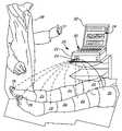
- FIG. 1is an exemplary representation of an arrangement of a vascular sensing system.
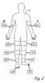
- FIG. 2is an exemplary representation of vascular testing locations.
- FIG. 3is a block diagram of a diagnostic test unit.
- FIG. 4is a graph of a cuff pressure signal over time, as cuff pressure is gradually decreased.
- FIG. 5is a graph of resultant pressure oscillations in the cuff pressure signal of FIG. 4 .
- FIG. 6is a graph plotting peak-to-trough pressure amplitude of the pressure oscillations of FIG. 5 versus the corresponding cuff pressure of FIG. 4 .
- FIG. 7is a graph of a bell-shaped curve fitted to the plot of FIG. 6 .
- FIG. 8is a block diagram of a digit pressure filtering algorithm.
- FIG. 9is a graph of an amplified pressure signal.
- FIG. 10is a graph of a bias signal corresponding to the pressure signal of FIG. 9 .
- FIG. 11is a flow chart of a bleed rate adjustment algorithm.
- FIG. 12is a graph of resultant cuff pressure oscillations after adjustment.
- the present inventionrelates to a vascular testing system. More particularly, the present invention relates to a vascular testing system for non-invasive measurement of vascular pressure and flow characteristics in a primary care environment.
- PADperipheral arterial disease
- vascular testingin general, and particularly where a patient exhibits one or more symptoms of PAD, it is desirable to conduct vascular testing in a primary care environment. PAD symptoms are present when patients experience leg pain with exercise, experience leg pain at rest, have a non-healing wound on a foot or leg, or have numbness or discoloration in a foot or leg.
- patients over the age of 70 having decreased pedal pulses and patients over the age of 50 who smoke and/or have diabetes and have decreased pedal pulsesare at risk for PAD.
- Segmental sphygmomanometryis measurement of blood pressures at different portions, or segments, of a patient's body. Bilateral vascular measurements are measurements taken along symmetrical segments of a patient's body, for instance, left and right ankles, and left and right forearms. Segmental sphygmomanometry allows comparisons of blood pressures between segments and between symmetrically paired locations, which can provide information as to conditions of corresponding blood vessels.
- One important and well-known segmental blood pressure indicatoris the ankle-brachial index (ABI).
- PVRpulse volume recording
- FIG. 1is an exemplary representation of an arrangement of a vascular testing system 20 .
- the vascular testing system 20includes a diagnostic test unit 22 having a single air outlet 24 , and one or more pressure applicators 26 .
- the diagnostic test unit 22can be connected to a computer 30 having a display 32 for providing an interface 34 with the vascular testing system 20 .
- the vascular testing system 20is utilized in a primary care environment for sensing and testing vascular conditions of a patient 36 .
- a care provider 38such as a lab technician or a primary care physician, can position the one or more pressure applicators 26 along the patient's 36 body.
- the one or more pressure applicators 26are oscillometric pressure cuffs.
- Each of the pressure applicators 26can be positioned at an exterior location along the patient's 36 body for sensing vascular pressures at desired vascular locations, such as at toes, ankles, thighs and arms.
- One or more pressure applicators 26can be placed on a patient's 36 body at a time.
- the diagnostic test unit 22includes a single air outlet 24 such that only one pressure applicator 26 can be connected to the diagnostic test unit 22 at a time.
- the interface 34permits display of instructions for guiding the care provider 38 through a process of engagement and disengagement of particular pressure applicators 26 positioned at particular vascular locations, (such as those shown in FIG. 2 ) to the air outlet 24 of the diagnostic test unit 22 .
- Each of the pressure applicators 26can be attached to the air outlet 24 of the diagnostic test unit 22 , in fluid communication therebetween. Tubing or other suitable connectors can be used to connect each of the pressure applicators 26 to the diagnostic test unit 22 . Because the diagnostic test unit 22 has a single air outlet 24 in the embodiment shown in FIG. 1 , only a single pressure applicator 26 is connected to the diagnostic test unit 22 at one time. This minimizes a risk of improper connections, and generally simplifies set-up of the vascular testing system 20 .
- the diagnostic test unit 22is capable of continuously streaming raw pressure data to the interface 34 during operation.
- the diagnostic test unit 22can be connected to the computer 30 , which can be a PC type desktop or laptop computer.
- the computer 30permits, inter alia, collecting, sorting, interpretering, organizing, displaying and transmitting data from the diagnostic test unit 22 .
- the computer 30operatively communicates with the interface 34 .
- the interface 34permits interaction with the vascular testing system 20 by the care provider 38 .
- the interface 34 in the primary care environmentallows display of measurements sensed by the vascular testing system 20 , such as current pressure reading values and captured waveform data.
- the interface 34further allows the care provider 38 to enter patient data to a database, which facilitates coordination of various patient data with information collected as part of vascular testing.
- the interface 34can include forms and displays for patient information, insurance information, history/risk factors, visit data, indications of a test, results of a test, interpretation (this function can be disabled until the test is signed by a qualified diagnosing physician), and reporting.
- the interface 34can provide suitable appointment, scheduling and billing functionality.
- the interface 34includes software compatible with Microsoft WINDOWS operating systems.
- the interface 34may include other types of software (e.g., software compatible with UNIX, LINUX, MACINTOSH, or other operating systems).
- the vascular testing system 20can be connected to the Internet, via a modem or other similar device, for communicating with servers and a remote interface.
- data collected in the primary care environmentcan be transmitted over the Internet or other network, via file transfer protocol (FTP) or other suitable means, to a database server (not shown) that in turn communicates with an interface (not shown) physically remote from the primary care environment, such as at a specialized vascular laboratory.
- FTPfile transfer protocol
- Datacan thereby be transmitted, with appropriate compression and/or encryption, between an interface on a technician-side (e.g., the interface 34 in the primary care environment) and a specialist-side interface (e.g., an interface in a vascular laboratory).
- Transmittal of vascular data collected in the primary care environmentcan be transmitted to a qualified interpreting physician, such as a specialist in an appropriate vascular field, for interpreting the data and making a diagnosis.
- An Internet-compatible vascular testing systemcan be configured such as that described in U.S. patent application Ser. No. 10/227,770, entitled SYSTEM AND METHOD FOR TESTING FOR CARDIOVASCULAR DISEASE, which is hereby incorporated by reference in its entirety.
- FIG. 2is an explementary representation of vascular testing locations, including arm locations 40 L and 40 R, thigh locations 42 L and 42 R, calf locations 44 L and 44 R, ankle locations 46 L and 46 R, and toe locations 48 L and 48 R.
- Segmental pressure testingcan be conducted at vascular locations such as the arm locations 40 L and 40 R, the ankle locations 46 L and 46 R, and the toe locations 48 L and 48 R.
- PVR testingcan be conducted at vascular locations such as the thigh locations 42 L and 42 R, the calf locations 44 L and 44 R, and the ankle locations 46 L and 46 R.
- Pressure measurements at particular vascular locationsare generally taken over a period of about 15 seconds to about 60 seconds.
- FIG. 3is a block diagram of the diagnostic test unit 22 .
- the diagnostic test unit 22includes a central processing unit (CPU) 70 , reset and supervisory circuitry 72 , non-volatile memory 74 , a bridge 76 , an external connector 78 , a medical power supply 80 , an internal power regulator 82 , and means for controlling pressure in a pressure applicator including a motor driver 84 , an electric motor 86 (e.g., a DC motor), a micro-diaphragm pump 88 , a first valve 90 , a first valve 92 , a proportional valve driver 94 , a variable orifice valve 96 (e.g., a proportional valve), a relief valve 98 , a pressure sensor 100 , and an air outlet 24 .
- the diagnostic test unitalso includes a signal processor 102 .
- the diagnostic test unit 22can further include a power entry 104 and an power switch 106 .
- the reset and supervisory circuitry 72 and non-volatile memory 74are operatively connected to the CPU 70 .
- the external connector 78which can be a universal serial bus (USB) connector, is operatively connected to the CPU 70 via the bridge 76 .
- the medical power supply 80provides two distinct supply voltages to the diagnostic test unit 22 (e.g., providing voltages of 12 volts and 5 volts).
- the medical power supply 80further supplies power to the internal regulator 82 , which in turn can supply power at a third voltage (e.g., 3.3 volts).
- the electric motor 86is operatably connected to the mirco-diaphragm pump 88 and to the CPU 70 via the motor driver 84 .
- the micro-diaphragm pump 88is in fluid communication with the first valve 92 , which is operatably connected to the CPU 70 via the first valve driver 90 .
- the variable orifice valve 96is in fluid communication with the first valve 92 , and is operatably connected to the CPU 70 via the variable orifice valve driver 94 .
- the relief valve 98is in fluid communication with the variable orifice valve 96 .
- the pressure sensor 100is in fluid communication with the relief valve 98 and the air outlet 24 .
- the pressure sensor 100is disposed between the valves 92 , 96 , 98 and the air outlet 24 , and does not contact a patient's body. Further, output from the pressure sensor 100 can be transmitted to the signal processor 102 , which is electrically connected to the CPU 70 .
- the CPU 70provides control of functions of the diagnostic test unit 22 , such as actuating the electric motor 86 and controlling valves (e.g., the variable orifice valve 96 ).
- the CPU 70is a model HD64F2317 16 Bit CPU available from Hitachi America, Ltd., Brisbane, Calif.
- the external connector 78permits the diagnostic test unit 22 to be connected to other devices, such as the computer 30 shown in FIG. 1 .
- the electric motor 86drives the micro-diaphragm pump 88 to generate a fluid displacement pressure.
- a fluid displaced by the micro-diaphragm pump 88is air.
- the micro-diaphragm pump 88is connected in fluid communication with a series of one or more valves 92 , 96 , 98 by suitable tubing or the like.
- a one-way check valve(not shown) can be included with the micro-diaphragm pump 88 for preventing fluid flow back through the pump 88 .
- the first valve 92is generally positioned adjacent the micro-diaphragm pump 88 .
- the first valve 92is an on/off valve capable of connecting a fluid path to the pressure applicator 26 to either the pump (i.e., an “on” position) or to atmosphere (i.e., an “off” position).
- the variable orifice valve 96is positioned adjacent the first valve 92 and distal to the micro-diaphragm pump 88 .
- the variable orifice valve 96has a variable orifice size capable of dynamically changing.
- the variable orifice valve 96is a special proportional valve model EV-P-10-2507, available from Clippard Instrument Laboratory, Inc., Cincinnati, Ohio.
- the relief valve 98is a mechanical valve positioned adjacent the variable orifice valve 96 and distal to the micro-diaphragm pump 88 .
- the relief valve 98facilitates safety monitoring by permitting the vascular testing system 20 to prevent pressure in a pressure applicator from exceeding a maximum value. For example, pressure in a pressure applicator can be prevented from exceeding about 240 millimeters mercury (mmHg) (e.g., using a 4.6 PSI relief valve).
- mmHgmillimeters mercury
- the pressure sensor 100permits measurement of pressures at any pressure applicator connected to the air outlet 24 , thereby allowing measurement of vascular characteristics at a corresponding vascular location. Signals from the pressure sensor 100 are transmitted to the signal processor 102 .
- the signal processor 102can provide various standard forms of signal processing, such as analog-to-digital conversion, filtering, buffering, and gain adjustments.
- the signal processor 102can be an analog signal processor. Signals are transmitted from the signal processor 102 to the CPU 70 . Additional safety protocol can be used.
- the first valve 92can be used to prevent pressures from remaining in the system more than a pre-determined period of time.
- pressures at and above about 220 mmHgmay be allowed only for a period of 5 seconds, and any significant system pressure (e.g., a system pressure at and above about 15 mmHg) may be allowed only for a period of 180 seconds.
- the first valve 92can be used to release pressure (e.g., vent fluid to the atmosphere).
- one or more pressure applicators or pressure cuffsare positioned at vascular locations at which a vascular pressure measurement is to be performed.
- An operative pressure cuffis first inflated to a pressure higher than a patient's systolic blood pressure, which occludes a blood vessel (i.e., causes a portion of a blood vessel to collapse and stop blood flow) at the vascular location.
- the particular level of pressure to which the operative pressure cuff is inflatedis determined by the care provider 38 operating the vascular testing system 20 .
- pressure in the operative pressure cuffis automatically and gradually lessened.
- Pressureis gradually lessened in a slow, controlled manner (e.g., at a rate of about 3 to about 5 mmHg/second). Oscillations in pressure at the operative pressure cuff are caused by the patient's artery as the pressure in the pressure cuff is gradually decreased.
- Pressurecan be decreased in a number of ways, such as by decreasing the pressure supplied by the micro-diaphragm pump 88 or by adjusting the orifice size of the variable orifice valve 96 .
- the size of the variable orifice valve 96is utilized to adjust the applied pressure.
- the orifice size of the variable orifice valve 96changes in order to maintain a generally linear decrease in pressure applied to the operative pressure cuff.
- a fixed orifice valvewould exhibit an exponential bleed rate, whereas a generally linear bleed rate is desired. Size of the orifice can be controlled with software operative through the CPU 70 .
- Use of the variable orifice valve 96 to control applied pressure at an operative pressure applicatorpermits pressure readings to be obtained quickly.
- FIG. 4is a graph of a cuff pressure signal over time, as cuff pressure is gradually decreased. It is desirable to decrease the cuff pressure in a generally linear manner. Oscillations in pressure at the operative pressure cuff are recorded and amplified by the vascular testing system 20 . Such oscillations are indicative of blood flow conditions at the vascular location.
- the cuff pressure signalis adjusted to compensate for the decreasing pressure applied to the operative pressure cuff by the micro-diaphragm pump 88 . Generally, this involves removing the ramp-shaped bias signal corresponding to the pressure applied to the operative pressure cuff.
- FIG. 5is a graph of result in pressure oscillations in the cuff pressure signal of FIG. 4 after adjustment. Calculations, adjustments, and other appropriate data manipulation can generally be accomplished through software. Calculations, waveform analysis, and other data manipulation can be accomplished through the computer 30 and software of the interface 34 . In further embodiments, software for performing calculations, etc., can be operative through the CPU 70 of the diagnostic test unit 22 .
- FIG. 6is a graph plotting peak-to-trough pressure amplitude of the pressure oscillations of FIG. 5 versus the corresponding cuff pressure of FIG. 4 .
- FIG. 6represents raw data points corresponding to the amplitudes of the pressure oscillations.
- FIG. 7is a graph of a bell-shaped curve fitted to the plot of FIG. 6 .
- a peak amplitude of the curve, A Maxis determined.
- a Maxis typically determined according the bell-shaped curve, rather than by the raw data points themselves.
- a return of blood flowis determined as a ratio of A Max .
- a value A Ris identified at a pre-determined percentage (e.g., seventy-five percent [75%]) of A Max .
- the value of A Ris indicative of a pressure oscillation amplitude at which blood flow returns at the vascular location.
- the pressure P Rcorresponds to a pressure measurement obtained by care providers using known types of vascular testing equipment (e.g., Doppler flow sensors).
- Vascular testing at some vascular locationsis facilitated by additional filtering and data processing.
- vascular locations on digitssuch as on a toe, require the use of relatively small pressure cuffs sized to fit those locations.
- Vascular testing using relatively small pressure cuffspresents significant concerns with signal noise. In such situations, a signal-to-noise ratio is more problematic than for vascular measurements taken with relatively large pressure cuffs used on ankles, arms, etc.
- Methods of digit pressure filteringcan be used to alleviate concerns with noise for vascular testing at vascular locations on digits.
- FIG. 8is a block diagapham of a digit pressure filtering algorithm.
- the digit pressure filtering algorithmis useful in taking pressure measurements at a vascular location on a digit (e.g., the toe locations 48 L and 48 R shown in FIG. 2 ).
- an amplified cuff pressure signalis obtained.
- the amplified cuff pressure signalis also passed through a low pass filter.
- a bias signalis determined after the amplified cuff pressure signal is filtered.
- a bleed rate change detectorpermits detection of a rate of change in applied pressure, as applied pressure is decreased. This permits the vascular testing system 20 to zero out sections of the bias signal where the bleed valve is being adjusted. Using the digit pressure filtering algorithm, the vascular testing system 20 can determine an output or resultant pressure.
- FIG. 9is a graph of an amplified pressure signal from a vascular location on a digit. This amplified pressure signal is similar to that shown and described with respect to FIG. 4 .
- FIG. 10is a graph of a bias signal curve corresponding to the pressure signal of FIG. 9 after filtering. Portions of negative flow in the bias signal followed by a window of positive flow are shown in FIG. 10 with a heavy line weight. Those weighted portions of the bias signal curve correspond to intervals where the bleed valve is being adjusted, meaning that an orifice size of a variable orifice (e.g., proportional) valve is changing. The orifice size of the variable orifice valve 96 changes in order to maintain a generally linear decrease in pressure applied to the pressure applicator 26 .
- a variable orificee.g., proportional
- FIG. 11is a flow chart of a bleed rate adjustment algorithm.
- the algorithm shown in FIG. 11permits opening of the valve more where a bleed rate is too low, and closing the valve more when the bleed rate is too high.
- countersare used to increment a counter value when the bleed rate is outside a desired range. When the counter reaches a pre-determined value (e.g., 25), the variable orifice valve 96 is opened or closed more, as appropriate.
- FIG. 12is a graph of resultant cuff pressure oscillations after adjustment. Changing the size of the orifice introduces noise signals. Adjustment involves removing the bias signal from the amplified pressure signal and zeroing out intervals of bleed valve adjustment (i.e., regions of the bias signal curve indicated with a heavy line weight).
- the resultant pressure graph of FIG. 12is similar to that shown in FIG. 5 .
- a return of flow pressure at the vascular locatione.g., the toe locations 48 L and 48 R shown in FIG. 2
- a pressure of return of blood flow, P Rcan be determined as a ratio of a peak pressure oscillation amplitude A Max , such as at a point A R that is75% of A Max .
- a pressure of return of blood flow, P Robtained using any of the equipment and processes shown and described above can be utilized in diagnoses of vascular conditions. Values of P R may differ from systolic pressures. Regardless, values of P R can be used in segmental comparisons like the ABI, in a manner similar to the systolic pressures traditionally used in the ABI.
- the vascular testing system 20can further take sphygmomanometric measurements such as systolic, mean and diastolic blood pressures using conventional measurement techniques. Such conventional techniques will be readily apparent to those skilled in the art.
- vascular testing locationscan include locations on a patient's body other than those specifically enumerated above.
Landscapes
- Health & Medical Sciences (AREA)
- Life Sciences & Earth Sciences (AREA)
- Cardiology (AREA)
- Vascular Medicine (AREA)
- Biomedical Technology (AREA)
- Heart & Thoracic Surgery (AREA)
- Physiology (AREA)
- Biophysics (AREA)
- Pathology (AREA)
- Engineering & Computer Science (AREA)
- Veterinary Medicine (AREA)
- Physics & Mathematics (AREA)
- Medical Informatics (AREA)
- Molecular Biology (AREA)
- Surgery (AREA)
- Animal Behavior & Ethology (AREA)
- General Health & Medical Sciences (AREA)
- Public Health (AREA)
- Ophthalmology & Optometry (AREA)
- Measuring Pulse, Heart Rate, Blood Pressure Or Blood Flow (AREA)
Abstract
Description
Claims (21)
Priority Applications (1)
| Application Number | Priority Date | Filing Date | Title |
|---|---|---|---|
| US10/935,702US7214192B2 (en) | 2004-09-07 | 2004-09-07 | Vascular testing system |
Applications Claiming Priority (1)
| Application Number | Priority Date | Filing Date | Title |
|---|---|---|---|
| US10/935,702US7214192B2 (en) | 2004-09-07 | 2004-09-07 | Vascular testing system |
Publications (2)
| Publication Number | Publication Date |
|---|---|
| US20060052714A1 US20060052714A1 (en) | 2006-03-09 |
| US7214192B2true US7214192B2 (en) | 2007-05-08 |
Family
ID=35997172
Family Applications (1)
| Application Number | Title | Priority Date | Filing Date |
|---|---|---|---|
| US10/935,702Expired - LifetimeUS7214192B2 (en) | 2004-09-07 | 2004-09-07 | Vascular testing system |
Country Status (1)
| Country | Link |
|---|---|
| US (1) | US7214192B2 (en) |
Cited By (12)
| Publication number | Priority date | Publication date | Assignee | Title |
|---|---|---|---|---|
| US20090099465A1 (en)* | 2007-10-15 | 2009-04-16 | Summit Doppler Systems, Inc. | System and method for a non-supine extremity blood pressure ratio examination |
| US20100198062A1 (en)* | 2009-01-30 | 2010-08-05 | General Electric Company | Systems and methods for integrating hemodynamic and imaging examinations |
| US20100292592A1 (en)* | 2009-05-12 | 2010-11-18 | Angiologix Inc. | System and method of measuring changes in arterial volume of a limb segment |
| US7913015B2 (en)* | 2005-07-29 | 2011-03-22 | Medtronic, Inc. | Implantable medical device bus system and method |
| US20110190675A1 (en)* | 2010-02-03 | 2011-08-04 | Tyco Healthcare Group Lp | Fitting of Compression Garment |
| US20120065561A1 (en)* | 2010-09-03 | 2012-03-15 | Epoch Medical Innovations, Inc. | Device, system, and method for the treatment, prevention and diagnosis of chronic venous insufficiency, deep vein thrombosis, lymphedema and other circulatory conditions |
| US9211070B2 (en) | 2010-09-23 | 2015-12-15 | Cleveland Clinic Foundation | Evaluation of peripheral arterial disease in a patient using an oscillometric pressure signal obtained at a lower extremity of the patient |
| US9375150B2 (en) | 2012-04-25 | 2016-06-28 | Summit Doppler Systems, Inc. | Identification of pressure cuff conditions using frequency content of an oscillometric pressure signal |
| US10238306B2 (en) | 2006-02-20 | 2019-03-26 | Everist Genomics, Inc. | Method for non-evasively determining an endothelial function and a device for carrying out said method |
| US10314531B2 (en) | 2010-09-30 | 2019-06-11 | Kpr U.S., Llc | Monitoring compliance using venous refill detection |
| US11077011B2 (en) | 2015-10-09 | 2021-08-03 | Kpr U.S., Llc | Compression garment compliance |
| US11129533B2 (en) | 2017-02-24 | 2021-09-28 | Collaborative Care Diagnostics, LLC | Secure communications and records handling system and associated method |
Families Citing this family (17)
| Publication number | Priority date | Publication date | Assignee | Title |
|---|---|---|---|---|
| US20100081941A1 (en)* | 2006-03-22 | 2010-04-01 | Endothelix, Inc. | Cardiovascular health station methods and apparatus |
| US7717855B2 (en) | 2006-12-06 | 2010-05-18 | The Hospital For Sick Children | System for performing remote ischemic preconditioning |
| DE102007002951A1 (en)* | 2007-01-19 | 2008-07-31 | Isymed Gmbh | Cardiovascular device |
| SG176022A1 (en)* | 2009-05-13 | 2011-12-29 | Hospital For Sick Children | Performance enhancement |
| WO2011094730A2 (en)* | 2010-02-01 | 2011-08-04 | The Hospital For Sick Children | Remote ischemic conditioning for treatment and reventon of restenosis |
| SG10201502031XA (en) | 2010-03-31 | 2015-05-28 | Hospital For Sick Children | Use of remote ischemic conditioning to improve outcome after myocardial infarction |
| RU2012147442A (en) | 2010-04-08 | 2014-05-20 | Дзе Хоспитал Фор Сик Чилдрен | APPLICATION OF REMOTE ISCHEMIC CONDITIONING IN TRAUMATIC DAMAGE |
| CN101897580A (en)* | 2010-08-17 | 2010-12-01 | 上海三埃弗电子有限公司 | Device for blood pressure simultaneous measurement of limbs |
| US8764789B2 (en) | 2011-04-15 | 2014-07-01 | CellAegis Devices Inc. | System for performing remote ischemic conditioning |
| WO2013147738A1 (en)* | 2012-03-26 | 2013-10-03 | Draeger Medical Systems, Inc. | Multi-limb non-invasive blood pressure measurement |
| USD708338S1 (en) | 2012-08-15 | 2014-07-01 | CellAegis Devices Inc. | Cuff for remote ischemic conditioning |
| AU2013203746B2 (en) | 2013-03-15 | 2015-05-07 | Cellaegis Devices, Inc. | Gas Powered System for Performing Remote Ischemic Conditioning |
| US10252052B2 (en) | 2013-03-15 | 2019-04-09 | The Hospital For Sick Children | Methods relating to the use of remote ischemic conditioning |
| US10098779B2 (en) | 2013-03-15 | 2018-10-16 | The Hospital For Sick Children | Treatment of erectile dysfunction using remote ischemic conditioning |
| CA2942614A1 (en) | 2013-03-15 | 2014-10-16 | The Hospital For Sick Children | Methods for modulating autophagy using remote ischemic conditioning |
| JP6386094B2 (en)* | 2015-01-08 | 2018-09-05 | 富士フイルム株式会社 | Photoacoustic measuring device and photoacoustic measuring system |
| MX2023014243A (en)* | 2021-08-11 | 2024-01-12 | California Inst Of Techn | SYSTEMS AND METHODS FOR NON-INVASIVE MEASUREMENT OF PULSE PRESSURE WAVEFORM. |
Citations (26)
| Publication number | Priority date | Publication date | Assignee | Title |
|---|---|---|---|---|
| US3651798A (en) | 1970-05-15 | 1972-03-28 | Parke Davis & Co | Blood pressure indicator and noise |
| US4005701A (en) | 1975-06-11 | 1977-02-01 | Whittaker Corporation | Noise rejecting electronic sphygmomanometer and methods for measuring blood pressure |
| US4800892A (en) | 1986-07-21 | 1989-01-31 | Nippon Colin Co., Ltd. | Apparatus for inflating cuff for blood pressure monitoring system |
| US4830019A (en) | 1986-06-12 | 1989-05-16 | Omron Tateisi Electronics Co. | Electronic blood pressure meter |
| US4860759A (en) | 1987-09-08 | 1989-08-29 | Criticare Systems, Inc. | Vital signs monitor |
| US5337751A (en) | 1991-09-30 | 1994-08-16 | Siemens Medical Electronics, Inc. | Air flow control apparatus and method for an automatic blood pressure gauge |
| US5368039A (en) | 1993-07-26 | 1994-11-29 | Moses; John A. | Method and apparatus for determining blood pressure |
| US5427109A (en) | 1993-01-19 | 1995-06-27 | Hewlett-Packard Company | Method and apparatus for automatic non-invasive monitoring of a patient's blood pressure |
| US5477162A (en) | 1992-01-09 | 1995-12-19 | Abb Industry Oy | Method for determining the short-circuit inductance of an asynchronous machine |
| US5579776A (en) | 1995-01-13 | 1996-12-03 | Johnson & Johnson Medical, Inc. | Oscillometric blood pressure monitor with enhanced cuff pressure control |
| US5584299A (en) | 1994-07-26 | 1996-12-17 | Nihon Kohden Corporation | Heart pulse wave detecting device using iterative base point detection |
| US5606977A (en) | 1995-01-04 | 1997-03-04 | Critikon, Inc. | Oscillometric blood pressure monitor which automatically determines when to take blood pressure measurements |
| US5626151A (en) | 1996-03-07 | 1997-05-06 | The United States Of America As Represented By The Secretary Of The Army | Transportable life support system |
| US5651370A (en) | 1995-02-15 | 1997-07-29 | Johnson & Johnson Medical, Inc. | Detection of oscillometeric blood pressure complexes using correlation |
| US5810734A (en) | 1994-04-15 | 1998-09-22 | Vital Insite, Inc. | Apparatus and method for measuring an induced perturbation to determine a physiological parameter |
| US5858679A (en) | 1992-11-12 | 1999-01-12 | Fornace, Jr.; Albert J. | Method for determining the presence of functional p53 by measuring GADD45 protein expression |
| US6093152A (en) | 1998-10-30 | 2000-07-25 | Protocol Systems, Inc. | Pulse width modulation valve control for vital sign monitors |
| US6228036B1 (en)* | 1998-07-17 | 2001-05-08 | Citizen Watch Co., Ltd. | Electronic sphygmomanometer and method for measuring blood pressure |
| US6485429B2 (en) | 1998-05-28 | 2002-11-26 | Microlife Intellectual Property Gmbh | Method and a device for non-invasive measurement of the blood pressure and for detection of arrhythmia |
| US6520919B1 (en) | 2002-01-09 | 2003-02-18 | Colin Corporation | Inferior-and-superior-limb blood-pressure-index measuring apparatus |
| US6616613B1 (en)* | 2000-04-27 | 2003-09-09 | Vitalsines International, Inc. | Physiological signal monitoring system |
| US20030212334A1 (en) | 2002-05-07 | 2003-11-13 | Colin Corporation | Arteriostenosis inspecting apparatus and ankle-blood-pressure measuring apparatus |
| US6719703B2 (en)* | 2001-06-15 | 2004-04-13 | Vsm Medtech Ltd. | Method and apparatus for measuring blood pressure by the oscillometric technique |
| US6719702B2 (en) | 2001-08-21 | 2004-04-13 | Samsung Electronics Co., Ltd. | Apparatus and method for measuring blood pressure using linearly varying air pressure |
| US6740042B1 (en) | 2001-09-05 | 2004-05-25 | Biomedix, Inc. | Bilateral simultaneous doppler measurement of segmented sphygmomanometry |
| US20040249292A1 (en) | 2003-01-21 | 2004-12-09 | Davis Charles L. | Noninvasive method of measuring blood density and hematocrit |
- 2004
- 2004-09-07USUS10/935,702patent/US7214192B2/ennot_activeExpired - Lifetime
Patent Citations (26)
| Publication number | Priority date | Publication date | Assignee | Title |
|---|---|---|---|---|
| US3651798A (en) | 1970-05-15 | 1972-03-28 | Parke Davis & Co | Blood pressure indicator and noise |
| US4005701A (en) | 1975-06-11 | 1977-02-01 | Whittaker Corporation | Noise rejecting electronic sphygmomanometer and methods for measuring blood pressure |
| US4830019A (en) | 1986-06-12 | 1989-05-16 | Omron Tateisi Electronics Co. | Electronic blood pressure meter |
| US4800892A (en) | 1986-07-21 | 1989-01-31 | Nippon Colin Co., Ltd. | Apparatus for inflating cuff for blood pressure monitoring system |
| US4860759A (en) | 1987-09-08 | 1989-08-29 | Criticare Systems, Inc. | Vital signs monitor |
| US5337751A (en) | 1991-09-30 | 1994-08-16 | Siemens Medical Electronics, Inc. | Air flow control apparatus and method for an automatic blood pressure gauge |
| US5477162A (en) | 1992-01-09 | 1995-12-19 | Abb Industry Oy | Method for determining the short-circuit inductance of an asynchronous machine |
| US5858679A (en) | 1992-11-12 | 1999-01-12 | Fornace, Jr.; Albert J. | Method for determining the presence of functional p53 by measuring GADD45 protein expression |
| US5427109A (en) | 1993-01-19 | 1995-06-27 | Hewlett-Packard Company | Method and apparatus for automatic non-invasive monitoring of a patient's blood pressure |
| US5368039A (en) | 1993-07-26 | 1994-11-29 | Moses; John A. | Method and apparatus for determining blood pressure |
| US5810734A (en) | 1994-04-15 | 1998-09-22 | Vital Insite, Inc. | Apparatus and method for measuring an induced perturbation to determine a physiological parameter |
| US5584299A (en) | 1994-07-26 | 1996-12-17 | Nihon Kohden Corporation | Heart pulse wave detecting device using iterative base point detection |
| US5606977A (en) | 1995-01-04 | 1997-03-04 | Critikon, Inc. | Oscillometric blood pressure monitor which automatically determines when to take blood pressure measurements |
| US5579776A (en) | 1995-01-13 | 1996-12-03 | Johnson & Johnson Medical, Inc. | Oscillometric blood pressure monitor with enhanced cuff pressure control |
| US5651370A (en) | 1995-02-15 | 1997-07-29 | Johnson & Johnson Medical, Inc. | Detection of oscillometeric blood pressure complexes using correlation |
| US5626151A (en) | 1996-03-07 | 1997-05-06 | The United States Of America As Represented By The Secretary Of The Army | Transportable life support system |
| US6485429B2 (en) | 1998-05-28 | 2002-11-26 | Microlife Intellectual Property Gmbh | Method and a device for non-invasive measurement of the blood pressure and for detection of arrhythmia |
| US6228036B1 (en)* | 1998-07-17 | 2001-05-08 | Citizen Watch Co., Ltd. | Electronic sphygmomanometer and method for measuring blood pressure |
| US6093152A (en) | 1998-10-30 | 2000-07-25 | Protocol Systems, Inc. | Pulse width modulation valve control for vital sign monitors |
| US6616613B1 (en)* | 2000-04-27 | 2003-09-09 | Vitalsines International, Inc. | Physiological signal monitoring system |
| US6719703B2 (en)* | 2001-06-15 | 2004-04-13 | Vsm Medtech Ltd. | Method and apparatus for measuring blood pressure by the oscillometric technique |
| US6719702B2 (en) | 2001-08-21 | 2004-04-13 | Samsung Electronics Co., Ltd. | Apparatus and method for measuring blood pressure using linearly varying air pressure |
| US6740042B1 (en) | 2001-09-05 | 2004-05-25 | Biomedix, Inc. | Bilateral simultaneous doppler measurement of segmented sphygmomanometry |
| US6520919B1 (en) | 2002-01-09 | 2003-02-18 | Colin Corporation | Inferior-and-superior-limb blood-pressure-index measuring apparatus |
| US20030212334A1 (en) | 2002-05-07 | 2003-11-13 | Colin Corporation | Arteriostenosis inspecting apparatus and ankle-blood-pressure measuring apparatus |
| US20040249292A1 (en) | 2003-01-21 | 2004-12-09 | Davis Charles L. | Noninvasive method of measuring blood density and hematocrit |
Cited By (21)
| Publication number | Priority date | Publication date | Assignee | Title |
|---|---|---|---|---|
| US7913015B2 (en)* | 2005-07-29 | 2011-03-22 | Medtronic, Inc. | Implantable medical device bus system and method |
| US10238306B2 (en) | 2006-02-20 | 2019-03-26 | Everist Genomics, Inc. | Method for non-evasively determining an endothelial function and a device for carrying out said method |
| US20090099465A1 (en)* | 2007-10-15 | 2009-04-16 | Summit Doppler Systems, Inc. | System and method for a non-supine extremity blood pressure ratio examination |
| US20090099463A1 (en)* | 2007-10-15 | 2009-04-16 | Summit Doppler Systems, Inc. | System and method for a non-supine extremity blood pressure ratio examination |
| US20090099461A1 (en)* | 2007-10-15 | 2009-04-16 | Summit Doppler Systems, Inc. | System and method for a non-supine extremity blood pressure ratio examination |
| US20100198062A1 (en)* | 2009-01-30 | 2010-08-05 | General Electric Company | Systems and methods for integrating hemodynamic and imaging examinations |
| US8137273B2 (en) | 2009-01-30 | 2012-03-20 | General Electric Company | Systems and methods for integrating hemodynamic and imaging examinations |
| US20100292592A1 (en)* | 2009-05-12 | 2010-11-18 | Angiologix Inc. | System and method of measuring changes in arterial volume of a limb segment |
| US8057400B2 (en) | 2009-05-12 | 2011-11-15 | Angiologix, Inc. | System and method of measuring changes in arterial volume of a limb segment |
| US8657755B2 (en) | 2009-05-12 | 2014-02-25 | Angiologix, Inc. | System and method of measuring changes in arterial volume of a limb segment |
| US8257289B2 (en) | 2010-02-03 | 2012-09-04 | Tyco Healthcare Group Lp | Fitting of compression garment |
| US20110190675A1 (en)* | 2010-02-03 | 2011-08-04 | Tyco Healthcare Group Lp | Fitting of Compression Garment |
| US20120065561A1 (en)* | 2010-09-03 | 2012-03-15 | Epoch Medical Innovations, Inc. | Device, system, and method for the treatment, prevention and diagnosis of chronic venous insufficiency, deep vein thrombosis, lymphedema and other circulatory conditions |
| US9211070B2 (en) | 2010-09-23 | 2015-12-15 | Cleveland Clinic Foundation | Evaluation of peripheral arterial disease in a patient using an oscillometric pressure signal obtained at a lower extremity of the patient |
| US10314531B2 (en) | 2010-09-30 | 2019-06-11 | Kpr U.S., Llc | Monitoring compliance using venous refill detection |
| US12274559B2 (en) | 2010-09-30 | 2025-04-15 | Kpr U.S., Llc | Control unit for monitoring patient compliance with a compression therapy regimen |
| US9375150B2 (en) | 2012-04-25 | 2016-06-28 | Summit Doppler Systems, Inc. | Identification of pressure cuff conditions using frequency content of an oscillometric pressure signal |
| US11077011B2 (en) | 2015-10-09 | 2021-08-03 | Kpr U.S., Llc | Compression garment compliance |
| US11129533B2 (en) | 2017-02-24 | 2021-09-28 | Collaborative Care Diagnostics, LLC | Secure communications and records handling system and associated method |
| US11659995B2 (en) | 2017-02-24 | 2023-05-30 | Collaborative Care Diagnostics, Llc. | Secure communications and records handling system and associated method |
| US12178545B2 (en) | 2017-02-24 | 2024-12-31 | Collaborative Care Diagnostics, Llc. | Secure communications and records handling system and associated method |
Also Published As
| Publication number | Publication date |
|---|---|
| US20060052714A1 (en) | 2006-03-09 |
Similar Documents
| Publication | Publication Date | Title |
|---|---|---|
| US7214192B2 (en) | Vascular testing system | |
| US7166076B2 (en) | Vascular testing system | |
| US7172555B2 (en) | Vascular testing system | |
| EP1011436B1 (en) | Method and arrangement for blood pressure measurement | |
| KR100877753B1 (en) | Apparatus and method for measuring hemodynamic parameters | |
| US6338719B1 (en) | Method and system for detecting vascular conditions using an occlusive arm cuff plethysmograph | |
| JP6534936B2 (en) | Automated assessment of peripheral vascular status | |
| EP1970000A2 (en) | Method and apparatus for cufflessly and non-invasively measuring wrist blood pressure in association with communication device | |
| CN101229058A (en) | Initial calibration device for measuring arterial blood pressure by pulse wave transmission time method | |
| Thulin et al. | Measurement of blood pressure—a routine test in need of standardization | |
| Ng et al. | Progress on the development of the MediWatch ambulatory blood pressure monitor and related devices | |
| US20150157217A1 (en) | Analysis System for Cardiac Information and Analyzing Method Thereof | |
| EP2782496A1 (en) | Method and apparatus for non-invasive determination of cardiac output | |
| US20170196468A1 (en) | Method for an Accurate Automated Non-invasive Measurement of Blood Pressure Waveform and Apparatus to Carry Out the Same | |
| Balestrieri et al. | Calibration of automated non invasive blood pressure measurement devices | |
| EP4236778A1 (en) | Continuous, and cuff-less measurement of blood pressure by pulse wave acquisition and analysis using non-invasive sensors | |
| JP2019513062A (en) | Method of deriving systolic blood pressure and / or diastolic blood pressure of a subject | |
| WO2002024053A9 (en) | Monitoring central venous pressures and intravascular volume | |
| RAYBURN et al. | Portable blood pressure monitoring for borderline or mild hypertension during pregnancy | |
| KEERTHANA et al. | NON-INVASIVE CUFFLESS BLOOD PRESSURE MEASUREMENT | |
| Lacković | Inspection and testing of noninvasive blood pressure measuring devices | |
| Karmen-Chan | Investigation of Narrow-Width Cuffs for Wearable Upper-Arm Oscillometric Monitoring of Blood Pressure | |
| Alrashdi | Comparison Between Home Used BP Digital Device (Wrist) With Mercury Sphygmomanometer | |
| Ozsahin et al. | The design of a noninvasive blood pressure measurement device | |
| Lacković | Inspection and Testing of Noninvasive Blood Pressure Measuring Devices |
Legal Events
| Date | Code | Title | Description |
|---|---|---|---|
| AS | Assignment | Owner name:BIOMEDIX, INC., MINNESOTA Free format text:ASSIGNMENT OF ASSIGNORS INTEREST;ASSIGNORS:POLIAC, MARIUS;BLANCH, GARY WARNER;GLAVA, VICTOR FLORIN;AND OTHERS;REEL/FRAME:016763/0322;SIGNING DATES FROM 20041122 TO 20041223 | |
| FEPP | Fee payment procedure | Free format text:PAYOR NUMBER ASSIGNED (ORIGINAL EVENT CODE: ASPN); ENTITY STATUS OF PATENT OWNER: SMALL ENTITY | |
| STCF | Information on status: patent grant | Free format text:PATENTED CASE | |
| CC | Certificate of correction | ||
| REMI | Maintenance fee reminder mailed | ||
| FPAY | Fee payment | Year of fee payment:4 | |
| SULP | Surcharge for late payment | ||
| AS | Assignment | Owner name:COLLABORATIVE CARE DIAGNOSTICS, LLC, MINNESOTA Free format text:ASSIGNMENT OF ASSIGNORS INTEREST;ASSIGNOR:BIOMEDIX VASCULAR SOLUTIONS, INC.;REEL/FRAME:032674/0183 Effective date:20130626 Owner name:BIOMEDIX VASCULAR SOLUTIONS, INC., MINNESOTA Free format text:MERGER;ASSIGNOR:BIOMEDIX, INC.;REEL/FRAME:032689/0082 Effective date:20061212 | |
| FPAY | Fee payment | Year of fee payment:8 | |
| FEPP | Fee payment procedure | Free format text:PAYOR NUMBER ASSIGNED (ORIGINAL EVENT CODE: ASPN) Free format text:PAYER NUMBER DE-ASSIGNED (ORIGINAL EVENT CODE: RMPN) | |
| MAFP | Maintenance fee payment | Free format text:PAYMENT OF MAINTENANCE FEE, 12TH YR, SMALL ENTITY (ORIGINAL EVENT CODE: M2553); ENTITY STATUS OF PATENT OWNER: SMALL ENTITY Year of fee payment:12 |