US7213941B2 - Flexible perimeter lighting apparatus - Google Patents
Flexible perimeter lighting apparatusDownload PDFInfo
- Publication number
- US7213941B2 US7213941B2US10/824,890US82489004AUS7213941B2US 7213941 B2US7213941 B2US 7213941B2US 82489004 AUS82489004 AUS 82489004AUS 7213941 B2US7213941 B2US 7213941B2
- Authority
- US
- United States
- Prior art keywords
- leds
- lighting system
- extrusion
- printed circuit
- light
- Prior art date
- Legal status (The legal status is an assumption and is not a legal conclusion. Google has not performed a legal analysis and makes no representation as to the accuracy of the status listed.)
- Expired - Lifetime, expires
Links
- 238000001125extrusionMethods0.000claimsabstractdescription118
- 239000000463materialSubstances0.000claimsabstractdescription81
- 238000003491arrayMethods0.000claimsdescription17
- 229920001296polysiloxanePolymers0.000claimsdescription9
- 238000005452bendingMethods0.000claimsdescription6
- 230000000903blocking effectEffects0.000claims1
- 238000005286illuminationMethods0.000abstractdescription2
- 229910052754neonInorganic materials0.000description16
- GKAOGPIIYCISHV-UHFFFAOYSA-Nneon atomChemical compound[Ne]GKAOGPIIYCISHV-UHFFFAOYSA-N0.000description16
- 239000003086colorantSubstances0.000description15
- 238000000034methodMethods0.000description14
- 239000004020conductorSubstances0.000description9
- 238000004382pottingMethods0.000description6
- 230000008901benefitEffects0.000description5
- 210000001503jointAnatomy0.000description5
- 230000007246mechanismEffects0.000description4
- 230000000712assemblyEffects0.000description3
- 238000000429assemblyMethods0.000description3
- 238000003780insertionMethods0.000description3
- 230000037431insertionEffects0.000description3
- NIXOWILDQLNWCW-UHFFFAOYSA-Nacrylic acid groupChemical groupC(C=C)(=O)ONIXOWILDQLNWCW-UHFFFAOYSA-N0.000description2
- 239000000853adhesiveSubstances0.000description2
- 238000004026adhesive bondingMethods0.000description2
- 230000001070adhesive effectEffects0.000description2
- 238000004873anchoringMethods0.000description2
- 230000004907fluxEffects0.000description2
- 239000003292glueSubstances0.000description2
- 229920002379silicone rubberPolymers0.000description2
- 239000004945silicone rubberSubstances0.000description2
- 239000004820Pressure-sensitive adhesiveSubstances0.000description1
- 239000003990capacitorSubstances0.000description1
- 230000008859changeEffects0.000description1
- 230000008878couplingEffects0.000description1
- 238000010168coupling processMethods0.000description1
- 238000005859coupling reactionMethods0.000description1
- 238000011161developmentMethods0.000description1
- 230000018109developmental processEffects0.000description1
- 230000007613environmental effectEffects0.000description1
- 230000002452interceptive effectEffects0.000description1
- 238000012423maintenanceMethods0.000description1
- 230000003287optical effectEffects0.000description1
- 239000002245particleSubstances0.000description1
- 229920003023plasticPolymers0.000description1
- 239000004033plasticSubstances0.000description1
- 230000008569processEffects0.000description1
- 239000004065semiconductorSubstances0.000description1
- 239000007787solidSubstances0.000description1
- 125000000391vinyl groupChemical group[H]C([*])=C([H])[H]0.000description1
- 229920002554vinyl polymerPolymers0.000description1
- 239000002699waste materialSubstances0.000description1
Images


Classifications
- G—PHYSICS
- G09—EDUCATION; CRYPTOGRAPHY; DISPLAY; ADVERTISING; SEALS
- G09F—DISPLAYING; ADVERTISING; SIGNS; LABELS OR NAME-PLATES; SEALS
- G09F9/00—Indicating arrangements for variable information in which the information is built-up on a support by selection or combination of individual elements
- G09F9/30—Indicating arrangements for variable information in which the information is built-up on a support by selection or combination of individual elements in which the desired character or characters are formed by combining individual elements
- G09F9/33—Indicating arrangements for variable information in which the information is built-up on a support by selection or combination of individual elements in which the desired character or characters are formed by combining individual elements being semiconductor devices, e.g. diodes
- F—MECHANICAL ENGINEERING; LIGHTING; HEATING; WEAPONS; BLASTING
- F21—LIGHTING
- F21S—NON-PORTABLE LIGHTING DEVICES; SYSTEMS THEREOF; VEHICLE LIGHTING DEVICES SPECIALLY ADAPTED FOR VEHICLE EXTERIORS
- F21S4/00—Lighting devices or systems using a string or strip of light sources
- F21S4/20—Lighting devices or systems using a string or strip of light sources with light sources held by or within elongate supports
- F—MECHANICAL ENGINEERING; LIGHTING; HEATING; WEAPONS; BLASTING
- F21—LIGHTING
- F21V—FUNCTIONAL FEATURES OR DETAILS OF LIGHTING DEVICES OR SYSTEMS THEREOF; STRUCTURAL COMBINATIONS OF LIGHTING DEVICES WITH OTHER ARTICLES, NOT OTHERWISE PROVIDED FOR
- F21V21/00—Supporting, suspending, or attaching arrangements for lighting devices; Hand grips
- F21V21/005—Supporting, suspending, or attaching arrangements for lighting devices; Hand grips for several lighting devices in an end-to-end arrangement, i.e. light tracks
- F—MECHANICAL ENGINEERING; LIGHTING; HEATING; WEAPONS; BLASTING
- F21—LIGHTING
- F21V—FUNCTIONAL FEATURES OR DETAILS OF LIGHTING DEVICES OR SYSTEMS THEREOF; STRUCTURAL COMBINATIONS OF LIGHTING DEVICES WITH OTHER ARTICLES, NOT OTHERWISE PROVIDED FOR
- F21V21/00—Supporting, suspending, or attaching arrangements for lighting devices; Hand grips
- F21V21/08—Devices for easy attachment to any desired place, e.g. clip, clamp, magnet
- F21V21/088—Clips; Clamps
- F—MECHANICAL ENGINEERING; LIGHTING; HEATING; WEAPONS; BLASTING
- F21—LIGHTING
- F21V—FUNCTIONAL FEATURES OR DETAILS OF LIGHTING DEVICES OR SYSTEMS THEREOF; STRUCTURAL COMBINATIONS OF LIGHTING DEVICES WITH OTHER ARTICLES, NOT OTHERWISE PROVIDED FOR
- F21V23/00—Arrangement of electric circuit elements in or on lighting devices
- F21V23/06—Arrangement of electric circuit elements in or on lighting devices the elements being coupling devices, e.g. connectors
- F—MECHANICAL ENGINEERING; LIGHTING; HEATING; WEAPONS; BLASTING
- F21—LIGHTING
- F21Y—INDEXING SCHEME ASSOCIATED WITH SUBCLASSES F21K, F21L, F21S and F21V, RELATING TO THE FORM OR THE KIND OF THE LIGHT SOURCES OR OF THE COLOUR OF THE LIGHT EMITTED
- F21Y2115/00—Light-generating elements of semiconductor light sources
- F21Y2115/10—Light-emitting diodes [LED]
- G—PHYSICS
- G09—EDUCATION; CRYPTOGRAPHY; DISPLAY; ADVERTISING; SEALS
- G09F—DISPLAYING; ADVERTISING; SIGNS; LABELS OR NAME-PLATES; SEALS
- G09F13/00—Illuminated signs; Luminous advertising
- G09F13/18—Edge-illuminated signs
- G09F2013/1886—Special effects
- G09F2013/189—Three dimensional effects
- G09F2013/1895—Imitating a neon tube
Definitions
- This inventionrelates to an elongated lighting system and more particularly to an elongated and flexible lighting system using light emitting diodes as its light source.
- Perimeter or border lights(“perimeter lighting”) are commonly used on buildings to accentuate the structure, to draw customer attention to the building, and to provide safety lighting. Lighted signs are also commonly used with business to advertise products or to indicate whether the business is open or closed. Most conventional perimeter lighting systems and lighted signs use neon or fluorescent bulbs as the light source. Some of the disadvantages of these bulbs are that they have a relatively short life, are fragile and can consume a relatively large amount of power. Also, neon bulbs can experience difficulty with cold starting, which can lead to the bulb's failure.
- LEDslight emitting diodes
- LEDsare now being used in many different applications that were previously the realm of incandescent bulbs; some of these include displays, automobile taillights and traffic signals. As the efficiency of LEDs improve it is expected that they will be used in most lighting applications.
- U.S. Pat. No. 4,439,818 to Scheibdiscloses a lighting strip that utilizes LEDs as the light source.
- the stripis flexible in three dimensions and is useful in forming characters and is capable of providing uniform illumination regardless of the characters selected for display.
- the stripcomprises a flexible multi-layered pressure sensitive adhesive tape, having a plurality of triangle cutout sections on each side of the tape, with LEDs connected in a series with a resister.
- One disadvantage of this stripis that it cannot be cut to different lengths for different applications. Instead, different lengths of the strip must be used. Further, the light from the LEDs is not diffused to give the appearance of neon light, instead showing lighting “hot spots” along its length. This arrangement is not durable enough to withstand the conditions for outdoor use.
- the flexible tape and its adhesivecan easily deteriorate when continually exposed to the elements.
- U.S. Pat. No. 5,559,681 to Duartediscloses a flexible, self adhesive, light emissive material that can be cut into at least two pieces.
- the light emissive materialincludes a plurality of light electrically coupled light emissive devices such as light emitting diodes.
- the materialalso includes electric conductors for conducting electric power from a source of electric power to each of the light emissive devices. While this lighting arrangement is cuttable to different lengths, the light it emits is not dispersed so that it resembles neon light. This arrangement is also not durable enough to withstand the conditions for outdoor use.
- U.S. Pat. No. 4,521,839 to Cook et al.discloses a strip lighting system comprising a string of electrically connected light bulbs contained within a flexible tube.
- the tubeis of a waterproof material and is sealed at each end by a removable plug, so that the string of bulbs can be removed when necessary to be repaired or replaced.
- strip lightingis not suitable for replacing neon type perimeter lighting because the light from the individual light bulbs is not diffused and dispersed to give the appearance of a neon light source. Furthermore, no mechanism is disclosed for mounting the strip lighting to a structure. Another disadvantage is that the strip lighting uses light bulbs instead of LEDs, and light bulbs generally have a shorter life span and can consume more power than LEDs.
- PCT International Application Number PCT/AU98/00602discloses a perimeter light that uses LEDs as its light source and includes a light tube structure in which multiple LEDs are arranged within an elongated tube that diffuses or disperses the light from the LEDs.
- the perimeter lightis used to highlight or decorate one or more features of a structure, such as a roof edge, window, door or corner between a wall or roof section.
- This lightis not flexible and that it cannot be cut to match the length of a building's structural features. Instead, the perimeter lighting must be custom ordered or is mounted without fully covering the structural feature. Also, the connectors between adjacent sections of lighting are bulky and result in a visible junction between the sections. The light's tube also significantly attenuates the light emitted by its LEDs, significantly reducing the light's brightness. There is also no apparatus or method for providing perimeter lighting that can be bent to match a curved structural feature of a building.
- an elongated flexible lighting systemcomprises an array of light sources that are illuminated by electric power. It further comprises an elongated translucent extrusion of flexible material.
- the array of light sourcesis integral to the extrusion with said extrusion transmitting and dispersing the light from the array such that the lighting system gives the appearance that the array of light sources is a continuous light source.
- One embodiment of a system for lighting structural featurescomprises a plurality of elongated flexible lighting systems, each of which includes an array of light sources that are illuminated by electric power. Each also includes an elongated translucent extrusion of flexible material with the array of light sources integral to the extrusion. The extrusion transmits and disperses light from the array giving the appearance that the array of light sources is a continuous light source.
- the flexible lighting systemscan be coupled in a daisy-chain with the electrical power transmitted to each of the flexible lighting systems.
- a mechanism for anchoring the flexible lighting systems to a structureis also included.
- an illuminated signcomprises a plurality of sign features formed using at least one elongated flexible lighting system.
- Each of the elongated lighting featurescomprises an array of light sources that are illuminated by electric power.
- Eachalso comprises an elongated translucent extrusion of flexible material with the array of light sources integral to the extrusion. The extrusion transmits and disperses light from the array giving the appearance that the array of light sources is a continuous light source.
- the flexible lighting systemsare coupled in a daisy-chain with the electrical power transmitted to each of said flexible lighting systems.
- a mechanismis also included for anchoring said flexible lighting systems in the shape of the sign features.
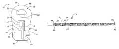
- FIG. 1is a perspective view of one embodiment of a elongated flexible lighting system according to the present invention
- FIG. 2is a sectional view of the lighting system in FIG. 1 , taken along section lines 2 — 2 ;
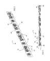
- FIG. 3is a perspective view of one embodiment of printed circuit assembly according to the present invention that can be used in flexible perimeter light of FIG. 1 ;
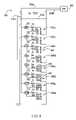
- FIG. 4is a schematic of one embodiment of the components and interconnects of a printed circuit assembly according to the present invention.
- FIG. 5is a plan view of one embodiment of a flexible printed circuit material and conductive traces according to the present invention.
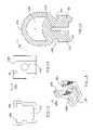
- FIG. 6is an elevation view of one embodiment of a mounting bracket according to the present invention.
- FIG. 7is an elevation view of one embodiment of a flexible lighting system according to the present invention mounted in the bracket of FIG. 6 ;
- FIG. 8is an elevation view of another embodiment of a mounting bracket according to the present invention.
- FIG. 9is an elevation view of one embodiment of a flexible lighting system according to the present invention mounted in the bracket of FIG. 8 ;
- FIG. 10is a perspective view of another embodiment of a flexible lighting system according to the present invention.
- FIG. 11is a sectional view of the flexible lighting system of FIG. 10 , taken along section lines 11 — 11 ;
- FIG. 12is an elevation view of a mounting bracket according to the present invention.
- FIG. 13is a plan view of the bracket in FIG. 12 ;
- FIG. 14is perspective view of still another mounting bracket according to the present invention.
- FIG. 15is an end view of another flexible extrusion according to the present invention.
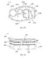
- FIG. 16is a sectional view of another embodiment of a flexible lighting system according to the present invention.
- FIG. 17is a perspective view of the lighting system shown in FIG. 16 ;
- FIG. 18is a plan view of one embodiment of a joint rod according to the present invention.
- FIG. 19is an end view of the joint rod in FIG. 18 ;
- FIG. 20is a perspective view of one embodiment of a butt joint fitting according to the present invention.
- FIG. 21is a front plan view of the butt joint fitting shown in FIG. 20 ;
- FIG. 22is a side plan view of the butt joint fitting in FIG. 20 ;
- FIG. 23is a top view of the butt joint fitting in FIG. 20 ;
- FIG. 24is a perspective view of one embodiment of an end cap according to the present invention.
- FIG. 25is a front plan view of the end cap in FIG. 24 ;
- FIG. 26is a side plan view of the end cap in FIG. 24 ;
- FIG. 27is a top view of the end cap in FIG. 24 ;
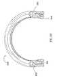
- FIG. 28is a perspective view of an embodiment of a flexible lighting system according to the present invention, flexed in the vertical plane;
- FIG. 29is a perspective view of an embodiment of a flexible lighting system according to the present invention, flexed in the vertical plane;
- FIG. 30is one embodiment of a sign using flexible lighting systems according to the present invention.
- FIG. 31is one embodiment of a structural feature using flexible lighting systems according to the present invention.
- FIGS. 1 and 2show one embodiment of a flexible lighting system 10 according to the present invention that generally comprises an elongated flexible extrusion 12 and an elongated flexible printed circuit assembly 14 .
- the extrusion 12can be many shapes and sizes, but is preferably sized to replace conventional neon lighting. Some standard sizes for neon lighting include, but are not limited to, 12 millimeter (mm), 15 mm, and 18 mm, and the extrusion can be sized accordingly to appear as these lights.
- the lighting systemshould also have optical properties designed to match and replace industry standard neon lights.
- the lighting systems according to the present inventioncan use light sources (such as LEDs) that are more efficient and have a longer life than conventional neon lights. The resulting lighting system can cost less over its lifetime, consume less power, and require less maintenance, compared to conventional neon lighting.
- the printed circuit assembly 14is mounted integrally with the flexible extrusion 12 , preferably in a lower longitudinal cavity 16 in the extrusion 12 , although the PCB can be arranged in many different ways adjacent to or within the extrusion 12 and can be formed as part of the extrusion 12 .
- the printed circuit assembly 14can be mounted vertically within longitudinal cavity 16 and can hold light sources 15 (shown best in FIG. 2 ) directed up toward the top rounded surface 18 of the extrusion 12 .”
- the lower longitudinal cavity 16can have a cross-section with many different shapes and sizes to match different arrangements of light sources 15 on the printed circuit assembly 14 .
- the longitudinal cavity 16has a larger upper portion 17 to house the upper part of the printed circuit material 14 and the lighting sources 15 .
- the longitudinal cavity 16also has a smaller lower portion 19 to house the lower part of the printed circuit material 14 and any electronic components mounted thereto.
- the longitudinal cavity 16is preferably arranged to completely enclose the printed circuit material 14 , with a cavity slot 16 provided for insertion of the printed circuit material 14 into the lower longitudinal cavity 16 during the assembly process.
- the longitudinal cavity 16can then be filled with a potting material to cover, seal and protect the printed circuit assembly 14 , with a suitable potting material being silicone.
- the printed circuit assembly 14can be conformal coated for protection prior to being installed in the longitudinal cavity.
- the extrusion 12 with its flexible printed circuit assembly 14 and light sources 15are arranged so that when the light sources are emitting, the perimeter lighting appears similar to neon lighting.
- the lighting system 10provides a number of advantages beyond conventional neon lights, only one of which is that it can be bent into tight curves, with some embodiments being capable of bending to a radius of less than 1′′ radius.
- the lighting system 10provides a further advantage of returning back to straight if the bending force is removed.
- the lighting systemis arranged such that it can be repeatedly bent and returned without damage to or failure to the extrusion 12 and/or the printed circuit assembly 14 .
- the lighting system 10has features that also allow it to appear as a continuous light source, with no lighting “hot spots” from its light sources 15 .
- the extrusion 12contains an upper longitudinal cavity 20 arranged between the printed circuit assembly 14 and the extrusions top surface 18 .
- the upper cavity 20has a generally semicircle cross section, although other cross sections can also be used. At least some of the light from the light sources 15 passes through the upper longitudinal cavity 20 before exiting from the top surface 18 .
- the upper longitudinal cavity 20provides for “secondary optics”, which help to diffuse the light from the light sources 15 .
- the light from the light sources 15first passes through the extrusion middle layer 22 .
- the extrusion 12can also have the opacity to further diffuse but not over-attenuate the emitting light.
- the extrusion's opacityalong with its secondary optics allow the lighting system 10 to appear as conventional neon lighting.
- the extrusion 12should have filter characteristics that transmit primarily the wavelength of the light emitted from the light sources.
- the upper cavity 20can have many different shapes and sizes and that lighting systems according to the present invention can be provided without upper cavities.
- Other mechanisms for diffusing the lightcan also be included such as scattering particle of voids.
- the extrusion 12also comprises first and second sides 26 , 28 that can be made thicker than the middle and top layers 22 , 24 , to give the perimeter lighting additional mechanical strength and to also block and absorb light from the light sources 15 that emits through the sides 26 , 28 . This reduces the amount of light that passes through the sides 26 , 28 and reduces/eliminates the light hot spots visible at the sides.
- the primary light emitted by the lighting system 10is through the extrusion top surface 18 .
- the light sources 15are preferably LEDs, although many other light sources can be used including, but not limited to, incandescent bulbs or solid state lasers.
- the LEDscan emit different wavelengths of light including, but not limited to, red, amber, yellow, green, blue and white.
- Each light sourcecan also be an LED capable of emitting multiple colors of light such as red, green and blue.
- the multiple colorscan be emitted individually or in combination to produce different color combinations of red, green and/or blue.
- the red, green and blue colorscan emit simultaneously to emit a white light combination of the colors.
- the intensity of each of the colorscan also be controlled, with the color changing and varying intensity manipulated by an electronic controller.
- the extrusion 12is formed using known extruding methods and can be made of many different flexible materials, with a preferred material being resilient and withstanding repeated flexing without damage or failure.
- the materialshould also be rugged, UV stable and capable of withstanding hot, cold, wet and dry environmental conditions, such that it can be used both inside and outside.
- the materialshould also be capable of being formed in many different colors and should experience only a small thermal expansion.
- a suitable extrusion materialis silicone, although many other materials can also be used.
- the extrusion 12can be mounted in place using many different methods including, but not limited to, gluing, screwing, nailing or clamping.
- the extrusionscontain first and second grooves 30 , 32 , each of which is on a respective one of the sides 26 , 28 of the extrusion 12 , near the bottom.
- the grooves 30 , 32mate with mounting brackets having lips. The brackets are first mounted to the structure, and the extrusion 12 snaps into the brackets with a respective one of the bracket lips disposed within one of the grooves 30 , 32 .
- FIG. 3shows one embodiment of a printed circuit assembly 40 according to the present invention having light sources 42 that are preferably LEDs, although other light sources can also be used.
- the LEDs 42can emit different colors and combinations of light as described above, and can be different types of LEDs such as surface mount and bi-pin through hole mounted LEDs.
- the LEDs 42 shown in FIG. 3are bi-pin through hole mounted LEDs, with each of the LEDs 42 having first and second mounting pins 44 , 46 that are each bent at approximately a 90 degree angle.
- the ends of the first and second mounting pins 44 , 46are coupled to a flexible printed circuit material 48 that can be made of any many different flexible materials having conductive traces, such as commercially available FR4 and Capton.
- the printed circuit material 48includes conductive traces that interconnect the LEDs 42 and other electronic devices 50 .
- the devices 50can be many electronic components including, but not limited to, resistors, voltage regulators, capacitors, inductors, transformers, etc.
- FIG. 4is a schematic showing the electronic components and interconnects for one embodiment of a printed circuit assembly 60 according to the present invention.
- a power supply 62provides power to the assembly 60 , which can operate from many different low or high voltage AC or DC supplies.
- a suitable power supply 62can provide 12 volt (V) DC power and in one embodiment a step down transformer (not shown) is used to reduce the typical 120V AC power to the suitable 12V DC.
- the power supply 62can be connected to the assembly 60 along conventional conductors or wires 63 a , 63 b .
- the 12V DC poweris then applied to an LED array 64 , which, in different embodiments, can comprise different numbers of LEDs 66 emitting in different colors.
- the LED arraycomprises 24 LEDs, which are grouped into eight LED sub-arrays 68 a–h , each having three LEDs.
- the LED array 64can include a different number of LEDs and sub-arrays, each of which can have more or less LEDs.
- Each of the sub-arrays 68 a–his arranged in parallel with the others and each includes a voltage regulator 70 and a resistor 72 .
- Each voltage regulator 70is arranged so that the same voltage is available at each sub-array 68 a–h , with a suitable voltage being approximately 1.25V.
- a suitable voltage regulatorbeing the commercially available LM317L 3-Terminal Adjustable Regulator, provided by National Semiconductor Corporation.
- a different resistor 72can be used at each of the sub-arrays 68 a–h depending on the voltage supplied by each voltage regulator 70 and the desired current to be applied to each sub-array 68 a–h .
- the desired currentcan be different.
- a suitable current to apply to each sub-arrayis 30 milliamps (mA), which results in suitable resistor 70 being 42 Ohms.
- the voltage regulator 70 and sub-array arrangement 68 a–hallows the LEDs 62 to illuminate with substantially the same luminous flux. Without this arrangement, the array 64 could experience line loss such that the initial LEDs in the array could emit a greater luminous flux compared to those further down the array. This would result in the overall lighting system appearing brighter at one end.
- the voltage regulator 70 at each sub-array 68 a–hprovides the same voltage at each sub-array 68 a–h , and if each resistor 72 is the same, substantially the same current is applied to the LEDs in each sub-array 68 a–h .
- a lighting system using the assembly 60will have substantially uniform brightness along its length.
- the circuit assembly 60transfers the 12V power from the one end to the other and around the sub-arrays 68 a–h along first and second daisy-chain conductors 74 a , 74 b .
- the conductors 74 a , 74 bcan then be connected to another next circuit assembly 60 in line, i.e. the conductors 74 a , 74 b can provide the 12V DC power supply to the next circuit assembly 60 .
- Thisallows a plurality of lighting systems to be “daisy chained” together to illuminate longer structural features or to form a number of sign features.
- Each circuit assembly 60typically comprises a flexible printed circuit material that is 12 inches long to hold the LEDs and electronic components.
- the circuit assembly 60typically is mounted within and illuminates 12 inches of flexible extrusion.
- a conventional 12V DC power supplycan power up to 20 circuit assemblies and can accordingly illuminate up to 20 feet of extrusion.
- Other power suppliescan power greater lengths of circuit assemblies 60 and the use of different electronic components can increase or decrease the length of circuit assemblies that can be powered.
- one of the advantages of the new lighting system 10is that it can be cut to match the length of a particular structural feature or to form different letters. This provides the ability to mount the flexible lighting system 10 on various structural features or to form various letters, without having to special order different lengths of lights to match the application.
- Each of the sub-arrays 68 a–htypically covers approximately 1.5 inches on its flexible printed circuit material and the printed circuit material can be cut between each of the sub-arrays 68 a–h , while allowing the remaining sub-arrays to emit light. This allows each of the 12 inch lengths in the lighting system 10 to be cut in the field in increments of 1.5 inches.
- Longer lengths of the lighting systemcan also be cut at 12 inch increments, essentially between each daisy chained printed circuit assembly 60 . This provides the advantage of allowing the daisy chain conductors 74 a , 74 b that would otherwise pass to the cut away section from the remainder of the light system, to be revealed. The cut-away section can then be re-used by coupling the revealed conductors to a 12V DC power supply. This helps reduce waste when the light system is being cut in the field.
- the flexible extrusioncan contain marks along its length, preferably along its bottom surface, to designate the proper locations for cutting between sub-arrays 68 a–h .
- one of the markscorresponds to the location between LED sub-arrays 68 b and 68 c so that cutting at the mark would remove parallel LED sub-arrays 68 c–h , leaving sub-arrays 68 a and 68 b to emit light.
- the LEDscan be surface mount LEDs, instead of the bi-pin LEDs.
- the surface mount LEDscan be side emitting such that they emit up when the printed circuit assembly is in its vertical orientation.
- the surface mount LEDscan also be designed to have a wide viewing angle and high intensity, with the pitch of the LEDs optimized for even light intensity.
- the LEDscan also be mounted on the flexible printed circuit material and centered in the extrusion.
- FIG. 5shows one embodiment of a flexible printed circuit material 80 , with traces 82 arranged for surface mount LEDs.
- redundant conductive paths or traces 82are provided to and from each surface mount pad 84 to add reliability during flexing of the lighting system.
- the redundant tracesare in opposing 90° directions so that if one trace cracks during flexing the other traces will still conduct current to the mount pad 84 .
- Through hole viasare used on the surface mount of the pad 84 to mechanically fix the pad to the printed circuit material. This keeps the pad 84 from lifting off the printed circuit material and breaking the trace.
- the printed circuit material 80can also be arranged in sub-arrays of LEDs that allow the material 80 to be cut in the field.
- Through hole pads 86are used at each end of the printed circuit material 80 to mechanically and electrically connect multiple printed circuit materials together in a daisy-chain. This allows the daisy-chained materials 80 to be used to illuminate different lengths of flexible extrusion or sign features.
- FIGS. 6 and 7show one embodiment of a mounting clip 90 according to the present invention that can be used to mount the flexible lighting system 92 according to the present invention, although many other mounting devices/methods can be used including, but not limited to, clamps, screws, glues, buttons, etc.
- the clip 90can be different lengths depending on the desired curve for the lighting system 92 .
- the clip 90contains inward facing and opposing first and second lips 94 , 96 , that are located to fit within a respective one of the first and second grooves 98 , 100 in the lighting system 92 .
- the clipcan be mounted in the desired location using many different known mounting methods, including but not limited to, screws, nails, glue, clips or clamps.
- the lighting system 92is pushed into the clip 90 until the first and second lips 94 , 96 mate with their respective one of the first and second grooves 98 , 100 .
- the lip and groove arrangementholds the lighting system 92 within the clip 90 .
- a number of shorter length clips 90can be mounted along the desired curve and the light system 92 can be mounted along a straight line or one or more longer clips can be used.
- FIGS. 8 and 9show another embodiment of a clip 110 according to the present invention that is also used for mounting different embodiments of a flexible lighting system 112 according to the present invention.
- the clip 110is similar to the clip 90 above and has first and second opposing lips 114 , 116 to mate with first and second grooves 118 , 120 to hold the lighting system in the clip 110 .
- the clip 110also comprises first and second vertical extensions 122 , 124 that extend above the opposing lips 114 , 116 , to provide lateral support to the sides of the lighting system 112 .
- the clip 110can be made of clear material or can be opaque to block light emitting through the side surfaces.
- FIGS. 10 and 11show another embodiment of a flexible lighting system 130 according to the present invention that is similar to lighting system 10 described above and generally comprises an elongated flexible extrusion 132 . It also comprises an elongated flexible printed circuit assembly 134 mounted integrally with the flexible extrusion 132 , preferably in the extrusion's longitudinal lower cavity 136 . Alternatively, the assembly 134 can be arranged in many different ways adjacent to or within the extrusion 132 .
- the printed circuit assembly 134is arranged vertically within the lower longitudinal cavity 136 and also holds LEDs 138 directed up toward the top rounded surface 140 of the extrusion 132 , such that light from the LEDs 138 primarily emits out the top surface 140 .
- the lower longitudinal cavity 136has a rectangular cross-section that can be formed with or without a longitudinal opening/slot to allow insertion of the printed circuit assembly.
- a slotcan be cut along the lower longitudinal cavity 136 to provide the opening for insertion of the printed circuit assembly 134 .
- the preferred location for the slotis along the bottom surface of the extrusion 132 , through to the cavity 136 , although the slot can be in many different locations.
- the slotcan be cut using many different methods, such as cutting with a razor or knife.
- the printed circuit assembly 134is preferably inserted into the longitudinal cavity 136 , through the slot with the LEDs 138 directed up toward the extrusion's top surface.
- the longitudinal cavitycan then be filled with a potting material, such as silicone, to surround and protect the printed circuit assembly 134 and its components.
- a potting materialsuch as silicone
- the printed circuit assembly 134can be slid into the longitudinal cavity 136 through one of its openings.
- Printed circuit assembly 134can have many different components and can be formed of many different materials, with a preferred circuit assembly 134 being similar to the assembly 14 shown in FIGS. 1–3 and describe above.
- the lighting system 130also has features similar to lighting system 10 that allow it to appear as conventional neon lighting.
- the extrusion 132contains an upper longitudinal cavity 142 arranged between the printed circuit material 134 and the extrusions top surface 140 .
- the upper longitudinal cavity 142has a generally semicircle cross section and light from the LEDs 138 passes through the second longitudinal cavity 142 before exiting from the top surface 140 .
- the upper longitudinal cavity 142 and the middle and upper extrusion layers 144 , 146allow for “secondary optics”, which helps refract and diffuse light from the LEDs. This arrangement helps diffuse the light without absorbing most of it, helping the lighting system 130 to exhibit its translucent characteristics and to appear as conventional neon lighting.
- the extrusion 132should have filter characteristics that transmit primarily the wavelength of light emitted from the LEDs 138 .
- the lighting system 130has first and second sides 148 , 150 that can be made thicker than the middle and upper layers 144 , 146 , which gives the perimeter lighting mechanical strength and also helps block and absorb light from the light sources that emits out the sides 148 , 150 of the extrusion 132 . This allows most of lighting system's emitted light to be the diffused light emitting out the extrusion top surface 140 .
- the LEDs 138can emit different wavelengths of light including, but not limited to, red, amber, yellow, green, blue and white.
- Each light sourcecan also be an LED capable of emitting multiple colors of light such as red, green and blue.
- the emission and intensity of each of the colorscan be controlled, with the color changing and varying intensity manipulated by an electronic controller.
- the extrusion 132can be formed using the same methods as extrusion 12 and can be made of the same material, such as silicone.
- the extrusion 132can be mounted in place in many different ways including, but not limited to, gluing, screwing, nailing or clamping.
- the extrusion 132contains first and second longitudinal grooves 152 , 154 , each of which is on a respective one of the extrusion side surfaces. Referring also to FIGS. 12 and 13 which show a mounting bracket 160 , the first and second grooves 152 , 154 are arranged to mate with the first and second opposing lips 161 , 162 for mounting the lighting system 130 .
- the bracket 160can be first mounted to the location where the lighting system is to be mounted, such as to a structure or as part of a sign.
- the bracket 160can be mounted using many different mounting methods, with a suitable method being screwing or nailing the bracket 160 in place through mounting hole 163 .
- the extrusion 132snaps into the bracket 160 with a respective one of the bracket lips 161 , 162 disposed within one of the first and second grooves 152 , 154 .
- the bracket 160can be made of many different materials, with a suitable material being acrylic, and can be formed using known methods.
- a number of shorter length clips 160can be mounted along the desired curve and the light system 130 can be mounted in the clips 160 to hold it in the desired curve.
- a number of shorter length clips 160can be mounted along a straight line or one or more longer clips can be used.
- FIG. 14shows still another embodiment of a mounting bracket 164 that can be used to mount lighting systems according to the present invention and comprises first and second opposing lips 165 , 166 to mate with the extrusion grooves 152 , 154 to hold the extrusion within the bracket.
- the bracket 164further comprises a mounting base 167 having a mounting hole 168 for nailing or screwing the bracket in place.
- FIG. 15shows still another embodiment of extrusion 170 that can be used in flexible lighting systems according to the present invention. It comprises a lower cavity 172 for holding a printed circuit assembly (not shown) having LEDs directed to its top surface 174 that is then encased in a potting material in the cavity 172 to protect the circuit assembly and its components.
- the extrusionalso has upper longitudinal cavity 176 having a crescent cross-section to provide secondary optics to refract and diffuse light from the LEDs.
- the extrusion 170has first and second sides 178 , 180 that can be made relatively thick to give the extrusion mechanical strength and also helps block and absorb light from out the sides 178 , 180 of the extrusion 170 .
- the extrusion 170can be formed using the same methods as extrusions 12 and 132 described above, and can be made of the same material, such as silicone.
- the extrusion 170further comprises first and second longitudinal grooves 182 , 184 , each of which is arranged to mate with a bracket lip for mounting the extrusion 170 .
- FIGS. 16 and 17show another embodiment of a flexible lighting system 190 according to the present invention that is similar to the lighting system 130 described above in conjunction with FIGS. 10 and 11 .
- the lighting system 190comprises an extrusion 192 and a printed circuit assembly 194 in the extrusion's longitudinal cavity 196 .
- the extrusion 192has a top rounded surface and first and second sides 200 , 202 with first and second mounting grooves 204 , 206 .
- the printed circuit assembly 194is arranged vertically in the longitudinal cavity 196 and comprises light sources 208 (preferably LEDs) mounted to a flexible printed circuit material 210 such that light from the LED is directed primarily through the top surface 198 .
- the printed circuit material 210is adjacent to one of the vertical surfaces of the longitudinal cavity 196 .
- the lighting system 190also comprises a strip 212 of material in the longitudinal cavity 196 , on the cavity's vertical surface opposite the printed circuit material 210 .
- the light sources 208are sandwiched between the strip 212 and material 210 , with both the strip 212 and material 210 being essentially opaque.
- the longitudinal cavity 196can then be filled with a commercially available silicone potting material. In operation, light from the light sources 208 that emits toward the extrusion side surfaces 200 , 202 is blocked from emitting through the side surfaces 200 , 202 by the strip 212 and the printed circuit material 210 . This essentially prevents lighting hot spots along the extrusions side surfaces 200 , 202 , with the LED light emitting through the top surface 198 .
- Many different materialscan be used for the strip 212 , with a suitable material being grey silicone, and the strip can be arranged in different location or integral with the printed circuit assembly 194 .
- FIGS. 18 and 19show one embodiment of a joint tube 220 according to the present invention that is used at the junction between the systems to provide a rugged as essentially seamless joint.
- the tubeis sized to fit in the upper cavities of the extrusions, such as the upper cavity 20 of extrusion 12 shown in FIGS. 1 and 2 .
- a first portion 222 of the tube 220is inserted into the upper cavity of one extrusion and the remaining second portion is inserted into the upper cavity of the next extrusion on line, with the portions 222 , 224 being approximately half of the tube 220 .
- the ends of the extrusionscan then be primed and glued together, with the tube 220 embedded in the extrusions.
- the joint tube 220has a diameter that allows it to fit closely within the upper cavities of the extrusions, while not deforming the extrusions, with a suitable diameter being approximately 1 ⁇ 4 of an inch.
- the tube 220also is also long enough to effectively hold the extrusions together, while not interfering with the flexing of adjacent extrusion, with a suitable length being approximately 1 inch. It is understood that the tube can have many different diameters and lengths according to the present invention.
- the tube 220can also be made of many different materials with many different colors, with a preferred rod being made of clear vinyl material. In other embodiments, a joint rod can be used in the same way as a joint tube, with a preferred joint tube being made of acrylic or plastic.
- FIGS. 20 through 23show one embodiment of a butt joint fitting 230 according to the present invention that can also be included between end-to-end flexible lighting systems.
- the fitting 230essentially comprises first and second halves 232 , 234 , with the first half 232 sized to fit over the end of one extrusion and the second half 234 sized to fit over the next extrusion in line.
- the halves 232 , 234can be glued over their respective extrusion end to bond the extrusions together in the joint fitting 230 .
- the joint fitting 230also has a rod hole 236 to allow the joint rod 220 (shown in FIGS. 18 and 19 ) to be passed between end-to-end extrusions, through the joint fitting 230 .
- the joint fitting 230can be made of many different materials, with a preferred material being silicone rubber. It can also be many different colors but is preferably clear so that the light from the lighting systems can pass through the joint fitting 230 . During operation the fitting is essentially undetectable and provides a durable connection point between end-to-end lighting systems, particularly when used with the joint rod 220 .
- FIGS. 24 through 27show one embodiment of an end cap 240 according to the present invention that is sized to fit over the ends of the flexible lighting systems.
- the end cap 240can have different sizes and shapes to fit over the ends of the different sized and shaped extrusions according to the present invention.
- the end capcan be bonded in place over the end of an extrusion for protection and to cover the extrusion's cavities, such as the upper and longitudinal cavities 20 and 16 shown in FIGS. 1 and 2 .
- the end cap 240can be made of many different materials with different colors, but is preferably made of silicone rubber having the same color as its extrusion. When in place, the end cap 240 provides protection while giving a finished appearance to the lighting systems.
- FIG. 28shows a flexible lighting system 250 according to the present invention, which is bent to a desired curvature.
- the extrusion 252is made of flexible material so that it can be flexed under a minimal force, such as by hand, and will then return back to straight when the force is removed. The extrusion can withstand repeated bending without experiencing a failure.
- the printed circuit assembly 254has LEDs and electronic components mounted on a flexible printed circuit material that has conductive traces to interconnect the LEDs and electronic components.
- the circuit assembly 254is mounted vertically, which allows the lighting system 250 to be bent to very small radiuses in the horizontal plane. It can also be bent in the vertical plane, although because of the orientation of the printed circuit assembly 254 , it cannot be bent to as small a radius.
- FIG. 29shows another embodiment of a flexible lighting system 260 according to the present invention that can be flexed to smaller radiuses in the vertical plane. It comprises an extrusion 262 that is made of a material such as silicone, and includes a lower cavity 264 and an upper cavity 266 .
- the lower cavity 264holds a printed circuit assembly 268 , usually sealed in a potting material, and the upper cavity 266 provides secondary optics to diffuse light passing through it.
- the printed circuit assembly 268is horizontally oriented. This arrangement allows for small flexing radiuses in the vertical plane, with not as small of flexing radiuses in the horizontal plane.
- the system 260can also comprise two opaque strips (not shown) on the sides of the lighting elements to block light emitting out the side surfaces of the extrusion 262 .
- FIG. 30shows one embodiment of a sign 270 constructed using flexible lighting systems according to the present invention to form sign features, such as illuminated sign letters and/or illuminated borders.
- the sign 270can comprise a base 274 onto which mounting brackets 276 are mounted in the locations for forming letters 278 a–d and borders 280 a–b . Lighting systems can then be cut in the field to the appropriate length to form the letters 278 a–d and borders 280 a–b . The lengths are then snapped into the brackets 276 and the lengths are electrically daisy-chained together by conductors (not shown). Power is then supplied to the lengths to illuminate the LEDs within each of the lengths.
- FIG. 31shows one embodiment of daisy-chained lighting system 290 according to the present invention used to illuminate a structural feature 292 .
- the mounting brackets 294are affixed to the structural feature 292 at intervals along a line where the lighting system is to be attached.
- the individual flexible lighting systems 296can be snapped into the brackets 294 to fix the lighting systems 296 in place. More than one of the light systems 296 can be daisy-chained to light a longer structural feature with power applied to the lighting systems along conductor 298 .
- the lighting systems 296can also be mounted along curved structural features.
- FIGS. 30 and 31show use of flexible perimeter lighting according to the present invention in illuminated signs and for structural perimeter lighting. There are, however, many other applications for the perimeter lighting including, but not limited to, automotive accent lighting, safety lighting, pool, spa and fountain lighting, as well as many other uses.
- the printed circuit assemblycan be mounted in many different ways integral to the extrusion.
- the light sourcescan be mounted within the extrusion without the printed circuit material.
- the extrusioncan be many different shapes and colors and can be more than one color. Therefore, the spirit and scope of the invention should not be limited to their preferred versions described above.
Landscapes
- Engineering & Computer Science (AREA)
- General Engineering & Computer Science (AREA)
- Physics & Mathematics (AREA)
- General Physics & Mathematics (AREA)
- Theoretical Computer Science (AREA)
- Non-Portable Lighting Devices Or Systems Thereof (AREA)
- Illuminated Signs And Luminous Advertising (AREA)
- Arrangement Of Elements, Cooling, Sealing, Or The Like Of Lighting Devices (AREA)
Abstract
Description
Claims (17)
Priority Applications (7)
| Application Number | Priority Date | Filing Date | Title |
|---|---|---|---|
| US10/824,890US7213941B2 (en) | 2004-04-14 | 2004-04-14 | Flexible perimeter lighting apparatus |
| PCT/US2005/010497WO2005106320A1 (en) | 2004-04-14 | 2005-03-29 | Flexible perimeter lighting apparatus |
| EP05731250AEP1756471B1 (en) | 2004-04-14 | 2005-03-29 | Flexible perimeter lighting apparatus |
| DE602005007221TDE602005007221D1 (en) | 2004-04-14 | 2005-03-29 | FLEXIBLE ENVIRONMENT LIGHTING DEVICE |
| AT05731250TATE397186T1 (en) | 2004-04-14 | 2005-03-29 | FLEXIBLE ENVIRONMENTAL LIGHTING DEVICE |
| US11/729,150US7604376B2 (en) | 2004-04-14 | 2007-03-27 | Flexible perimeter lighting apparatus |
| US12/581,713US8215786B2 (en) | 2004-04-14 | 2009-10-19 | Flexible perimeter lighting apparatus |
Applications Claiming Priority (1)
| Application Number | Priority Date | Filing Date | Title |
|---|---|---|---|
| US10/824,890US7213941B2 (en) | 2004-04-14 | 2004-04-14 | Flexible perimeter lighting apparatus |
Related Child Applications (1)
| Application Number | Title | Priority Date | Filing Date |
|---|---|---|---|
| US11/729,150ContinuationUS7604376B2 (en) | 2004-04-14 | 2007-03-27 | Flexible perimeter lighting apparatus |
Publications (2)
| Publication Number | Publication Date |
|---|---|
| US20050231947A1 US20050231947A1 (en) | 2005-10-20 |
| US7213941B2true US7213941B2 (en) | 2007-05-08 |
Family
ID=34964328
Family Applications (3)
| Application Number | Title | Priority Date | Filing Date |
|---|---|---|---|
| US10/824,890Expired - LifetimeUS7213941B2 (en) | 2004-04-14 | 2004-04-14 | Flexible perimeter lighting apparatus |
| US11/729,150Expired - LifetimeUS7604376B2 (en) | 2004-04-14 | 2007-03-27 | Flexible perimeter lighting apparatus |
| US12/581,713Expired - Fee RelatedUS8215786B2 (en) | 2004-04-14 | 2009-10-19 | Flexible perimeter lighting apparatus |
Family Applications After (2)
| Application Number | Title | Priority Date | Filing Date |
|---|---|---|---|
| US11/729,150Expired - LifetimeUS7604376B2 (en) | 2004-04-14 | 2007-03-27 | Flexible perimeter lighting apparatus |
| US12/581,713Expired - Fee RelatedUS8215786B2 (en) | 2004-04-14 | 2009-10-19 | Flexible perimeter lighting apparatus |
Country Status (5)
| Country | Link |
|---|---|
| US (3) | US7213941B2 (en) |
| EP (1) | EP1756471B1 (en) |
| AT (1) | ATE397186T1 (en) |
| DE (1) | DE602005007221D1 (en) |
| WO (1) | WO2005106320A1 (en) |
Cited By (64)
| Publication number | Priority date | Publication date | Assignee | Title |
|---|---|---|---|---|
| US20070021026A1 (en)* | 2005-07-21 | 2007-01-25 | Wang Shih K | LED tube lights with clear bottom base |
| US20070058377A1 (en)* | 2005-09-15 | 2007-03-15 | Zampini Thomas L Ii | Interconnection arrangement having mortise and tenon connection features |
| US20070076427A1 (en)* | 2004-12-30 | 2007-04-05 | Ann Reo | Linear lighting apparatus with increased light- transmission efficiency |
| US20090021841A1 (en)* | 2007-07-17 | 2009-01-22 | Cree Led Lighting Solutions, Inc. | Optical elements with internal optical features and methods of fabricating same |
| US20090174542A1 (en)* | 2008-01-03 | 2009-07-09 | Sharon Gentry | System and method for increasing signage awareness and visibility |
| US20090195189A1 (en)* | 2007-01-26 | 2009-08-06 | I2Systems | Tri-light |
| US20090273300A1 (en)* | 2008-05-02 | 2009-11-05 | Kayser David J | Variable Intensity LED Illumination System |
| US20100061095A1 (en)* | 2006-12-28 | 2010-03-11 | Friedemann Hoffmann | Lighting device |
| US20100128483A1 (en)* | 2008-11-25 | 2010-05-27 | Cooper Technologies Company | Led luminaire |
| US20110084627A1 (en)* | 2009-10-13 | 2011-04-14 | Sloanled, Inc. | Shelf Lighting Device And Method |
| US20110110085A1 (en)* | 2009-11-12 | 2011-05-12 | Cooper Technologies Company | Light Emitting Diode Module |
| US20110170285A1 (en)* | 2010-01-14 | 2011-07-14 | Mai Mao-Kai | Lamp Support Structure for Lamp Tubes |
| US20120032587A1 (en)* | 2010-08-06 | 2012-02-09 | Shu-Chuan Shih | LED string light |
| USD668802S1 (en) | 2010-10-07 | 2012-10-09 | Finch Ronald V | Bicycle light |
| US8430756B2 (en) | 2010-05-11 | 2013-04-30 | Patent Rights Protection Group, Llc | Gaming machine cabinet with edge lighting |
| US8616720B2 (en) | 2010-04-27 | 2013-12-31 | Cooper Technologies Company | Linkable linear light emitting diode system |
| US8764220B2 (en) | 2010-04-28 | 2014-07-01 | Cooper Technologies Company | Linear LED light module |
| USD723204S1 (en)* | 2013-05-13 | 2015-02-24 | Triplet Music Products Inc. | Illumination device |
| US20150198289A1 (en)* | 2014-01-15 | 2015-07-16 | Chen-Wei Hsu | Light tube |
| US20150300608A1 (en)* | 2014-02-10 | 2015-10-22 | Michael S. Hartman | Lighting Element For Illuminated Hardscape |
| US20150330584A1 (en)* | 2014-05-13 | 2015-11-19 | Osram Gmbh | Lighting device and corresponding mounting housing, kit and method |
| US20170038036A1 (en)* | 2015-08-03 | 2017-02-09 | Salvatore Guerrieri | Cover for led strips |
| US20170350565A1 (en)* | 2014-02-10 | 2017-12-07 | Hartman Design, Inc. | Lighting element for illuminated hardscape |
| USD813954S1 (en) | 2015-09-24 | 2018-03-27 | Ags Llc | Game tower |
| USD818048S1 (en) | 2015-10-05 | 2018-05-15 | Ags Llc | Gaming machine |
| US9997010B2 (en) | 2015-12-18 | 2018-06-12 | Ags Llc | Electronic gaming device with external lighting functionality |
| US10002488B2 (en) | 2015-12-17 | 2018-06-19 | Ags Llc | Electronic gaming device with call tower functionality |
| USD820915S1 (en) | 2015-09-22 | 2018-06-19 | Ags Llc | Gaming machine |
| US10113718B2 (en) | 2014-04-23 | 2018-10-30 | General Led Opco, Llc | Retrofit system and method for replacing linear fluorescent lamp with LED modules |
| US20180347789A1 (en)* | 2017-01-31 | 2018-12-06 | Scott David Moore | Mounting device and packaging system for lighting product |
| USD843473S1 (en) | 2017-04-07 | 2019-03-19 | Ags Llc | Gaming machine |
| US10309614B1 (en) | 2017-12-05 | 2019-06-04 | Vital Vivo, Inc. | Light directing element |
| USD852890S1 (en) | 2017-11-30 | 2019-07-02 | Ags Llc | Gaming machine |
| US10357582B1 (en) | 2015-07-30 | 2019-07-23 | Vital Vio, Inc. | Disinfecting lighting device |
| US10413626B1 (en) | 2018-03-29 | 2019-09-17 | Vital Vio, Inc. | Multiple light emitter for inactivating microorganisms |
| USD865873S1 (en) | 2017-08-23 | 2019-11-05 | Ags Llc | Gaming machine |
| US10617774B2 (en) | 2017-12-01 | 2020-04-14 | Vital Vio, Inc. | Cover with disinfecting illuminated surface |
| USD882160S1 (en) | 2018-07-20 | 2020-04-21 | Roys Curtis A | LED clip |
| USD887033S1 (en) | 2018-04-02 | 2020-06-09 | Curtis Alan Roys | LED universal mount with integrated LEDs |
| USD888837S1 (en) | 2018-02-02 | 2020-06-30 | Ags Llc | Support structure for gaming machine display |
| USD890983S1 (en) | 2018-03-05 | 2020-07-21 | Curtis Alan Roys | LED mounting adapter |
| US10753575B2 (en) | 2015-07-30 | 2020-08-25 | Vital Vio, Inc. | Single diode disinfection |
| US10918747B2 (en) | 2015-07-30 | 2021-02-16 | Vital Vio, Inc. | Disinfecting lighting device |
| USD916359S1 (en) | 2018-03-05 | 2021-04-13 | Curtis Alan Roys | LED clip |
| US11002438B2 (en) | 2019-04-03 | 2021-05-11 | Sidney Howard Norton | Adjustable clip-on base for LED assembly |
| US11014312B2 (en)* | 2017-08-02 | 2021-05-25 | Shenzhen Thousandshores Technology Co., Ltd. | Silicone cold-extrusion lamp belt and manufacturing method thereof |
| US11022282B2 (en) | 2018-02-26 | 2021-06-01 | RetroLED Components, LLC | System and method for mounting LED light modules |
| US11037395B2 (en) | 2018-10-05 | 2021-06-15 | Aruze Gaming (Hong Kong) Limited | Gaming device display systems, gaming devices and methods for providing lighting enhancements to gaming devices |
| US11098887B1 (en) | 2020-12-10 | 2021-08-24 | Elemental LED, Inc. | Encapsulated linear lighting |
| US11162654B2 (en)* | 2017-11-14 | 2021-11-02 | Terry Patrick Walsh | Lighting units |
| USD939632S1 (en) | 2018-07-17 | 2021-12-28 | Ags Llc | Gaming machine |
| US20220105423A1 (en)* | 2020-10-05 | 2022-04-07 | Eric M. Meunier | Illuminated support rails for pinball machines |
| US11369704B2 (en) | 2019-08-15 | 2022-06-28 | Vyv, Inc. | Devices configured to disinfect interiors |
| US11380157B2 (en) | 2019-08-02 | 2022-07-05 | Ags Llc | Servicing and mounting features for gaming machine display screens and toppers |
| US11441760B2 (en) | 2018-02-26 | 2022-09-13 | Curtis Alan Roys | System and method for mounting LED light modules |
| USD969926S1 (en) | 2019-04-24 | 2022-11-15 | Ags Llc | Gaming machine |
| USD969927S1 (en) | 2019-08-02 | 2022-11-15 | Ags Llc | Gaming machine |
| US11541135B2 (en) | 2019-06-28 | 2023-01-03 | Vyv, Inc. | Multiple band visible light disinfection |
| USD978810S1 (en) | 2019-07-31 | 2023-02-21 | Ags Llc | LED matrix display |
| US11639897B2 (en) | 2019-03-29 | 2023-05-02 | Vyv, Inc. | Contamination load sensing device |
| US11878084B2 (en) | 2019-09-20 | 2024-01-23 | Vyv, Inc. | Disinfecting light emitting subcomponent |
| US12169066B2 (en) | 2018-10-04 | 2024-12-17 | Quarkstar Llc | Illumination device with elongated optical element with at least one cavity |
| US12194168B2 (en) | 2018-12-19 | 2025-01-14 | Vyv, Inc. | Lighting and dissipation device |
| US12251487B2 (en) | 2016-12-29 | 2025-03-18 | Vyv, Inc. | Electric light radiant energy control systems |
Families Citing this family (110)
| Publication number | Priority date | Publication date | Assignee | Title |
|---|---|---|---|---|
| US8376576B2 (en)* | 2001-07-25 | 2013-02-19 | The Sloan Company, Inc. | Perimeter lighting |
| US7090377B2 (en)* | 2004-05-20 | 2006-08-15 | Kuo-Pin Chen | Strip light |
| USD563036S1 (en)* | 2005-03-02 | 2008-02-26 | Nichia Corporation | Light emitting diode lens |
| CN101356404B (en)* | 2005-12-09 | 2012-11-07 | 完全创新控股有限公司 | Light guides, irradiated objects and equipment |
| US8398261B2 (en)* | 2005-12-30 | 2013-03-19 | Ge Lighting Solutions Llc | Lighting strips with improved manufacturability |
| DE102006011594A1 (en)* | 2006-03-10 | 2007-09-13 | Mross Jun., Ulrich | lighting device |
| EP2013532A1 (en)* | 2006-04-25 | 2009-01-14 | Koninklijke Philips Electronics N.V. | Led array grid, method and device for manufacturing said grid and led component for use in the same |
| DE102006031345A1 (en)* | 2006-07-06 | 2008-01-10 | Patent-Treuhand-Gesellschaft für elektrische Glühlampen mbH | Shapely flexible lighting system |
| WO2008047484A1 (en)* | 2006-10-20 | 2008-04-24 | Contents Co., Ltd. | Flexible luminescent material |
| WO2008134424A2 (en)* | 2007-04-24 | 2008-11-06 | Lumination Llc | Led perimeter lighting system |
| DE202007006688U1 (en)* | 2007-05-07 | 2008-09-18 | Hettich-Heinze Gmbh & Co. Kg | Guide rail fitting |
| US8398262B2 (en) | 2008-05-09 | 2013-03-19 | The Sloan Company, Inc. | Low profile extrusion |
| US8083370B2 (en)* | 2008-05-09 | 2011-12-27 | The Sloan Company, Inc. | Low profile extrusion |
| JP2012501068A (en)* | 2008-08-26 | 2012-01-12 | ディングォ パン | Light emitting diode multichip surface mount component and light bar manufactured by mounting the surface mount component |
| CN101387374A (en)* | 2008-10-21 | 2009-03-18 | 田德华 | Flexible color changing neon lamp for simple thin LED |
| US8297788B2 (en) | 2008-12-08 | 2012-10-30 | Avx Corporation | Card edge LED strip connector and LED assembly |
| US8382322B2 (en)* | 2008-12-08 | 2013-02-26 | Avx Corporation | Two part surface mount LED strip connector and LED assembly |
| CN101435538B (en)* | 2008-12-10 | 2010-06-02 | 黎美平 | Thin Diode Light Strip |
| CA2755508A1 (en)* | 2009-03-17 | 2010-09-23 | Koninklijke Philips Electronics N.V. | Led strip for small channel letters |
| USD626269S1 (en)* | 2009-03-20 | 2010-10-26 | Sylvan R. Shemitz Designs Incorporated | Luminaire |
| AT10807U3 (en)* | 2009-03-24 | 2010-05-15 | Garamanta Beteiligungs Gmbh | LIGHTING SYSTEM FOR HANDRAIL |
| DE102009021846A1 (en)* | 2009-05-19 | 2010-12-30 | Osram Gesellschaft mit beschränkter Haftung | Power supply module and light strip |
| USD621542S1 (en)* | 2009-11-13 | 2010-08-10 | Sylwester Klus | LED-based linear lighting apparatus housing |
| USD621091S1 (en)* | 2009-11-13 | 2010-08-03 | Klu Sacute Sylwester | External housing for LED-based linear lighting |
| USD621090S1 (en)* | 2009-11-13 | 2010-08-03 | Klu Sacute Sylwester | Housing for LED-based linear lighting apparatus |
| US8641535B2 (en)* | 2009-12-03 | 2014-02-04 | Patent Rights Protection Group, Llc | Gaming machine cabinet construction and method |
| USD623343S1 (en)* | 2010-01-18 | 2010-09-07 | Klu Grave Over S Sylwester | LED-based linear lighting apparatus with external housing |
| USD623342S1 (en)* | 2010-01-18 | 2010-09-07 | Klu Sacute Sylwester | External housing for LED-based linear lighting apparatus |
| USD625463S1 (en)* | 2010-01-18 | 2010-10-12 | Sylwester Klus | LED-based linear lighting apparatus with rounded housing |
| USD641923S1 (en)* | 2010-03-15 | 2011-07-19 | Valeriy Radchenko | Round extrusion for lighting fixtures |
| US8425075B1 (en)* | 2010-03-17 | 2013-04-23 | Bruce P. Falat | Lighting mounting device |
| USD637338S1 (en)* | 2010-03-25 | 2011-05-03 | Lg Innotek Co., Ltd. | LED lamp |
| IT1399323B1 (en)* | 2010-04-09 | 2013-04-16 | Simes | LED LIGHTING APPLIANCE |
| USD680679S1 (en)* | 2010-04-10 | 2013-04-23 | Lg Innotek Co., Ltd. | LED lamp |
| US9004715B1 (en)* | 2010-09-10 | 2015-04-14 | Emergency Technology, Inc. | Modular structural frame lighting |
| IT1402856B1 (en)* | 2010-10-28 | 2013-09-27 | Posa S P A | LED STRIPES ENCAPSED IN FLEXIBLE SLEEVES IN SILICON ELASTOMERABLE, COLD VULCANIZABLE, RELATIVE PROCESS OF PREPARATION AND THEIR USE AS SEALS |
| US9797560B2 (en)* | 2010-11-16 | 2017-10-24 | Dialight Corporation | LED luminaire utilizing an extended and non-metallic enclosure |
| US9033542B2 (en) | 2010-11-16 | 2015-05-19 | Dialight Corporation | LED luminaire utilizing an extended and non-metallic enclosure |
| IT1403915B1 (en)* | 2011-02-04 | 2013-11-08 | Luxall S R L | LED, OLED, EL LIGHT SOURCES, ENCAPSULATED FOR CO-EXTRUSION IN A COLD VULCANIZABLE SILICONE ELASTOMER INCLUDING THERMOCONDUCTIVE MATERIALS AND ITS PREPARATION PROCESS |
| USD685130S1 (en)* | 2011-03-09 | 2013-06-25 | Lg Innoteck Co., Ltd. | LED lamp |
| DE102011001680A1 (en)* | 2011-03-30 | 2012-10-04 | W. Döllken & Co. GmbH | Method for producing an LED-based lighting fixture |
| USD681265S1 (en)* | 2011-04-26 | 2013-04-30 | Lg Innotek Co., Ltd. | LED lamp |
| DE102011075021A1 (en)* | 2011-04-29 | 2012-10-31 | Osram Ag | Semiconductor illumination tape i.e. flexible LED illumination tape, for illuminating image plane, has band shaped substrate retained in substrate retainer that is permeable for white mixture light emitted by laterally emitting LEDs |
| DE102011075523B4 (en)* | 2011-05-09 | 2014-12-11 | Osram Gmbh | LED array |
| CA2840244C (en)* | 2011-07-27 | 2018-04-03 | Grote Industries, Llc | System for lighting apparatus utilizing light active sheet material with integrated light emitting diode, window with lighting apparatus, conveyance with lighting apparatus, and method of providing lighting apparatus |
| DE102011082490A1 (en)* | 2011-09-12 | 2013-03-14 | Siemens Aktiengesellschaft | Light profile hose |
| US20130099685A1 (en)* | 2011-10-21 | 2013-04-25 | Gemmy Industries Incorporated | Flexible Tubular Lighting System |
| USD661010S1 (en)* | 2011-12-12 | 2012-05-29 | Azek Building Products, Inc. | Light strip for railings |
| US20130155713A1 (en)* | 2011-12-20 | 2013-06-20 | Calvin Chuen Kam Law | Flexible Light Bar With Epoxy |
| USD745736S1 (en)* | 2012-04-05 | 2015-12-15 | Michael W. May | Illuminating assembly |
| US9228727B2 (en) | 2012-04-05 | 2016-01-05 | Michael W. May | Lighting assembly |
| CN103375722A (en)* | 2012-04-26 | 2013-10-30 | 鹤山健豪灯饰企业有限公司 | Soft light bar allowing shearing and connecting |
| DE102012210742A1 (en) | 2012-06-25 | 2014-01-02 | Osram Gmbh | FLEXIBLE STRIPED PCB WITH LEDS |
| CN102748726A (en)* | 2012-07-09 | 2012-10-24 | 中山市科顺分析测试技术有限公司 | A LED flexible circuit board and its applied hose lamp |
| US20140313722A1 (en)* | 2013-04-17 | 2014-10-23 | Raw Thrills, Inc. | Flexible Decorative Lighted Strip, Cabinet Including Same, and Installation Method |
| DE202013101820U1 (en)* | 2013-04-26 | 2013-06-03 | Edgar Burr | Shaft lighting device and elevator shaft with such a shaft lighting device |
| US9115858B2 (en)* | 2013-05-09 | 2015-08-25 | Inspired LED, LLC | Extended length flexible LED light strip system |
| US9695991B2 (en)* | 2013-08-30 | 2017-07-04 | Itc Incorporated | Diffused flexible LED linear light assembly |
| US9909719B2 (en)* | 2013-08-30 | 2018-03-06 | Itc Incorporated | LED linear light assemblies with transparent bottoms |
| US10532693B2 (en) | 2013-08-30 | 2020-01-14 | Itc Incorporated | Diffused flexible LED linear light assembly |
| US9772076B2 (en)* | 2013-09-30 | 2017-09-26 | Osram Sylvania Inc. | Cuttable flexible light engines |
| TWM474657U (en)* | 2013-10-04 | 2014-03-21 | Chen-Wei Hsu | Light guide device for automobile light |
| US20150151674A1 (en)* | 2013-12-04 | 2015-06-04 | Chen-Wei Hsu | Rearview mirror with light tube |
| US20150217840A1 (en)* | 2014-02-04 | 2015-08-06 | Zachary Taylor | Light Altering Rub Rail and Rub Rail Insert |
| TWD163989S (en)* | 2014-04-17 | 2014-11-01 | 陳維宏 | LED lamp body |
| WO2015161217A1 (en) | 2014-04-18 | 2015-10-22 | May Michael W | Lighting assembly |
| US20160018089A1 (en)* | 2014-07-21 | 2016-01-21 | Grote Industries, Inc. | Lamp having multiple mountings |
| CN104315465A (en)* | 2014-10-13 | 2015-01-28 | 昆山博文照明科技有限公司 | Lamp body of inclined buckle type Christmas lamp |
| DE102014018016A1 (en)* | 2014-12-08 | 2016-06-09 | Paulmann Licht Gmbh | Holding device for at least one light source and elongated carrier for this purpose |
| KR102547293B1 (en) | 2015-02-10 | 2023-06-23 | 아이빔 머티리얼스 인코퍼레이티드 | Ion Beam Assisted Deposition Epitaxial Hexagonal Materials on Textured Substrates |
| USRE49869E1 (en) | 2015-02-10 | 2024-03-12 | iBeam Materials, Inc. | Group-III nitride devices and systems on IBAD-textured substrates |
| US10243105B2 (en) | 2015-02-10 | 2019-03-26 | iBeam Materials, Inc. | Group-III nitride devices and systems on IBAD-textured substrates |
| NO341997B1 (en)* | 2015-06-16 | 2018-03-12 | Marine Aluminium As | Elongated, hollow-shaped support strip for use in connection with walkways to ensure safe traffic in areas with poor lighting. |
| CA2905695C (en)* | 2015-09-03 | 2018-09-04 | Itc Incorporated | Led linear light assemblies with transparent bottoms |
| US10401020B2 (en)* | 2015-11-13 | 2019-09-03 | Brightz ltd. | Apparatus for illuminating outdoor bag toss game |
| US20170148363A1 (en)* | 2015-11-25 | 2017-05-25 | Darrell Frycz | Illuminated Sign Device |
| EP3400402B1 (en) | 2016-01-07 | 2020-12-23 | Michael W. May | Connector system for lighting assembly |
| CN105508915A (en)* | 2016-01-20 | 2016-04-20 | 中山国鳌智能科技有限公司 | LED flexible lamp belt |
| US9726332B1 (en) | 2016-02-09 | 2017-08-08 | Michael W. May | Networked LED lighting system |
| DE102016003733A1 (en)* | 2016-03-22 | 2017-05-04 | Diehl Aerospace Gmbh | Light module, luminaire and light module set |
| US10113707B2 (en)* | 2016-03-31 | 2018-10-30 | Cae Inc. | Illumination device for visually suppressing a gap between two adjacent reflective surfaces |
| US20200096179A1 (en) | 2016-07-29 | 2020-03-26 | Labyrinth Technologies, Llc | Localization systems and methods |
| US10697620B2 (en)* | 2018-06-21 | 2020-06-30 | Labyrinth Technologies, Llc | Flexible lighting and universal mounting system for municipal utility poles |
| KR102609510B1 (en)* | 2016-11-30 | 2023-12-04 | 엘지디스플레이 주식회사 | Foldable display device |
| US10190756B2 (en)* | 2017-02-02 | 2019-01-29 | 9609385 Canada Inc. | Flexible signaling device having rubberlike elongate diffuser |
| EP3652480B1 (en)* | 2017-07-13 | 2021-01-13 | Signify Holding B.V. | Light emitting strip |
| US10845034B2 (en)* | 2017-09-05 | 2020-11-24 | AVID Labs, LLC | Lighting system |
| TW201934923A (en)* | 2017-10-16 | 2019-09-01 | 荷蘭商露明控股公司 | Thermally stable flexible lighting device |
| US10731804B2 (en)* | 2018-01-24 | 2020-08-04 | Carl Boehmer | Traffic control system with flexible LED lighted assembly |
| IT201800005003A1 (en)* | 2018-05-02 | 2019-11-02 | Led lighting device. | |
| USD891646S1 (en) | 2018-06-28 | 2020-07-28 | Vista Manufacturing Inc | Light assembly |
| IT201800007704A1 (en)* | 2018-07-31 | 2020-01-31 | Teleco Automation Srl | PERFECTED ILLUMINATION DEVICE |
| IT201800007711A1 (en) | 2018-07-31 | 2020-01-31 | Teleco Automation Srl | PERFECTED PROFILE |
| US10845013B2 (en) | 2018-10-03 | 2020-11-24 | Vista Manufacturing Inc | Flexible light assembly |
| US10520143B1 (en)* | 2019-03-26 | 2019-12-31 | Elemental LED, Inc. | LED simulated neon with structural reinforcement |
| US11793593B2 (en)* | 2019-04-02 | 2023-10-24 | American Sterilizer Company | Lighting assemblies for medical device suspension system |
| AU2021214378B2 (en) | 2020-01-31 | 2024-02-29 | American Sterilizer Company | Lighting assembly and light head including same |
| EP4162200A4 (en)* | 2020-06-03 | 2024-07-31 | Lumileds LLC | FLEXIBLE LIGHTING DEVICE |
| CN112616215B (en)* | 2020-12-17 | 2024-05-07 | 绍兴欧能光电有限公司 | LED lamp tube assembling mechanism and assembling method thereof |
| US11906131B2 (en)* | 2021-04-23 | 2024-02-20 | PureEdge Lighting LLC | Flexible suspension lighting |
| ES2915270B2 (en) | 2021-12-14 | 2022-10-27 | Antares Iluminacion S A U | LIGHTING SYSTEM WITH A HOLLOW AND FLEXIBLE RAIL |
| ES2914342B2 (en) | 2021-12-14 | 2022-10-26 | Antares Iluminacion S A U | LIGHTING SYSTEM WITH A CONTINUOUS FLEXIBLE TRACK |
| US12098836B2 (en)* | 2022-02-09 | 2024-09-24 | Research & Design Innovations, Llc | Diffused lighting assemblies and methods of installation on marine vessels and land vehicles |
| JP7408172B2 (en)* | 2022-04-07 | 2024-01-05 | エイテックス株式会社 | Manufacturing method of LED lighting device |
| USD1032723S1 (en) | 2022-04-19 | 2024-06-25 | Ags Llc | Gaming machine |
| USD1032722S1 (en) | 2022-04-19 | 2024-06-25 | Ags Llc | Gaming machine |
| US11655946B1 (en)* | 2022-06-17 | 2023-05-23 | Bruce Zhang | Flexible LED illumination device |
| CN117869833A (en)* | 2023-03-16 | 2024-04-12 | 惠州柒海科技有限公司 | Novel flexible LED lighting device |
| US12117135B1 (en)* | 2023-03-30 | 2024-10-15 | Zhu Hai Fuyun Lighting Industrial Co., Ltd. | Light strip configured to facilitate shape forming and shaped light ornament composed thereof |
| US12038143B1 (en)* | 2023-03-30 | 2024-07-16 | Zhu Hai Fuyun Lighting Industrial Co., Ltd. | Light strip facilitated for shape forming and shaped light ornament formed therefrom |
Citations (18)
| Publication number | Priority date | Publication date | Assignee | Title |
|---|---|---|---|---|
| US4439818A (en) | 1983-02-25 | 1984-03-27 | Scheib Joseph J | Flexible light display with evenly distributed illumination |
| US4521839A (en) | 1984-02-09 | 1985-06-04 | Cook Brian A | Strip lighting system |
| US4597033A (en) | 1983-05-17 | 1986-06-24 | Gulf & Western Manufacturing Co. | Flexible elongated lighting system |
| US4712165A (en) | 1986-09-05 | 1987-12-08 | Cetrone Vincent B | Tubular overhead lighting system |
| US5099401A (en) | 1990-07-08 | 1992-03-24 | Stanley Electric Co., Ltd. | Signal lighting fixture for vehicles |
| US5559681A (en) | 1994-05-13 | 1996-09-24 | Cnc Automation, Inc. | Flexible, self-adhesive, modular lighting system |
| WO1998000602A1 (en) | 1996-06-28 | 1998-01-08 | Sunds Defibrator Industries Ab | Pressurized chlorine dioxide bleaching with recovery of chlorine dioxide |
| WO1999006759A1 (en) | 1997-07-28 | 1999-02-11 | Hewlett-Packard Company | Strip lighting |
| US6186645B1 (en)* | 1997-02-24 | 2001-02-13 | Itc, Inc. | Flexible lighting system and mounting arrangement |
| CA2282819A1 (en) | 1999-09-21 | 2001-03-21 | Lumion Corporation | Running board lighting assembly |
| US6283612B1 (en) | 2000-03-13 | 2001-09-04 | Mark A. Hunter | Light emitting diode light strip |
| US6361186B1 (en)* | 2000-08-02 | 2002-03-26 | Lektron Industrial Supply, Inc. | Simulated neon light using led's |
| US6394623B1 (en) | 2000-07-14 | 2002-05-28 | Neon King Limited | Translucent flexible rope light and methods of forming and using same |
| US6406166B1 (en) | 2000-05-30 | 2002-06-18 | Yu-Chow Ko | Chasing rope light |
| US20020191386A1 (en) | 2001-01-31 | 2002-12-19 | Cleaver Mark Joseph | Illumination device for simulation of neon lighting |
| US6776504B2 (en)* | 2001-07-25 | 2004-08-17 | Thomas C. Sloan | Perimeter lighting apparatus |
| US6874924B1 (en)* | 2002-03-14 | 2005-04-05 | Ilight Technologies, Inc. | Illumination device for simulation of neon lighting |
| US7012379B1 (en)* | 2003-03-27 | 2006-03-14 | Ilight Technologies, Inc. | Cuttable illumination device |
Family Cites Families (6)
| Publication number | Priority date | Publication date | Assignee | Title |
|---|---|---|---|---|
| US4529839A (en)* | 1983-10-25 | 1985-07-16 | At&T Bell Laboratories | Multilocation video conference terminal including an arrangement to reduce disruption in video switching |
| US5337225A (en) | 1993-01-06 | 1994-08-09 | The Standard Products Company | Lighting strip system |
| US5927845A (en)* | 1995-08-28 | 1999-07-27 | Stantech | Integrally formed linear light strip with light emitting diodes |
| US6158882A (en)* | 1998-06-30 | 2000-12-12 | Emteq, Inc. | LED semiconductor lighting system |
| AUPP729298A0 (en)* | 1998-11-24 | 1998-12-17 | Showers International Pty Ltd | Housing and mounting system for a strip lighting device |
| ATE380971T1 (en) | 1999-07-21 | 2007-12-15 | Teledyne Lighting & Display | LIGHTING DEVICE |
- 2004
- 2004-04-14USUS10/824,890patent/US7213941B2/ennot_activeExpired - Lifetime
- 2005
- 2005-03-29EPEP05731250Apatent/EP1756471B1/ennot_activeExpired - Lifetime
- 2005-03-29ATAT05731250Tpatent/ATE397186T1/ennot_activeIP Right Cessation
- 2005-03-29WOPCT/US2005/010497patent/WO2005106320A1/enactiveApplication Filing
- 2005-03-29DEDE602005007221Tpatent/DE602005007221D1/ennot_activeExpired - Lifetime
- 2007
- 2007-03-27USUS11/729,150patent/US7604376B2/ennot_activeExpired - Lifetime
- 2009
- 2009-10-19USUS12/581,713patent/US8215786B2/ennot_activeExpired - Fee Related
Patent Citations (19)
| Publication number | Priority date | Publication date | Assignee | Title |
|---|---|---|---|---|
| US4439818A (en) | 1983-02-25 | 1984-03-27 | Scheib Joseph J | Flexible light display with evenly distributed illumination |
| US4597033A (en) | 1983-05-17 | 1986-06-24 | Gulf & Western Manufacturing Co. | Flexible elongated lighting system |
| US4521839A (en) | 1984-02-09 | 1985-06-04 | Cook Brian A | Strip lighting system |
| US4712165A (en) | 1986-09-05 | 1987-12-08 | Cetrone Vincent B | Tubular overhead lighting system |
| US5099401A (en) | 1990-07-08 | 1992-03-24 | Stanley Electric Co., Ltd. | Signal lighting fixture for vehicles |
| US5559681A (en) | 1994-05-13 | 1996-09-24 | Cnc Automation, Inc. | Flexible, self-adhesive, modular lighting system |
| WO1998000602A1 (en) | 1996-06-28 | 1998-01-08 | Sunds Defibrator Industries Ab | Pressurized chlorine dioxide bleaching with recovery of chlorine dioxide |
| US6186645B1 (en)* | 1997-02-24 | 2001-02-13 | Itc, Inc. | Flexible lighting system and mounting arrangement |
| WO1999006759A1 (en) | 1997-07-28 | 1999-02-11 | Hewlett-Packard Company | Strip lighting |
| CA2282819A1 (en) | 1999-09-21 | 2001-03-21 | Lumion Corporation | Running board lighting assembly |
| US6283612B1 (en) | 2000-03-13 | 2001-09-04 | Mark A. Hunter | Light emitting diode light strip |
| US6406166B1 (en) | 2000-05-30 | 2002-06-18 | Yu-Chow Ko | Chasing rope light |
| US6394623B1 (en) | 2000-07-14 | 2002-05-28 | Neon King Limited | Translucent flexible rope light and methods of forming and using same |
| US6361186B1 (en)* | 2000-08-02 | 2002-03-26 | Lektron Industrial Supply, Inc. | Simulated neon light using led's |
| US20020191386A1 (en) | 2001-01-31 | 2002-12-19 | Cleaver Mark Joseph | Illumination device for simulation of neon lighting |
| US6592238B2 (en)* | 2001-01-31 | 2003-07-15 | Light Technologies, Inc. | Illumination device for simulation of neon lighting |
| US6776504B2 (en)* | 2001-07-25 | 2004-08-17 | Thomas C. Sloan | Perimeter lighting apparatus |
| US6874924B1 (en)* | 2002-03-14 | 2005-04-05 | Ilight Technologies, Inc. | Illumination device for simulation of neon lighting |
| US7012379B1 (en)* | 2003-03-27 | 2006-03-14 | Ilight Technologies, Inc. | Cuttable illumination device |
Non-Patent Citations (1)
| Title |
|---|
| Ilight Technologies, Introducting Plexineon, A Revolutionary and Versatile Lighting System for Architectural Applications, Jun. 21, 2002. |
Cited By (130)
| Publication number | Priority date | Publication date | Assignee | Title |
|---|---|---|---|---|
| US20070076427A1 (en)* | 2004-12-30 | 2007-04-05 | Ann Reo | Linear lighting apparatus with increased light- transmission efficiency |
| US7857482B2 (en)* | 2004-12-30 | 2010-12-28 | Cooper Technologies Company | Linear lighting apparatus with increased light-transmission efficiency |
| US7461947B2 (en)* | 2005-07-21 | 2008-12-09 | Leotek Electronics Corporation | LED tube lights with clear bottom base |
| US20070021026A1 (en)* | 2005-07-21 | 2007-01-25 | Wang Shih K | LED tube lights with clear bottom base |
| US7572027B2 (en)* | 2005-09-15 | 2009-08-11 | Integrated Illumination Systems, Inc. | Interconnection arrangement having mortise and tenon connection features |
| US20070058377A1 (en)* | 2005-09-15 | 2007-03-15 | Zampini Thomas L Ii | Interconnection arrangement having mortise and tenon connection features |
| US8366291B2 (en)* | 2006-12-28 | 2013-02-05 | Friedemann Hoffmann | Lighting device |
| US20100061095A1 (en)* | 2006-12-28 | 2010-03-11 | Friedemann Hoffmann | Lighting device |
| US20090195189A1 (en)* | 2007-01-26 | 2009-08-06 | I2Systems | Tri-light |
| US8013538B2 (en) | 2007-01-26 | 2011-09-06 | Integrated Illumination Systems, Inc. | TRI-light |
| US20090021841A1 (en)* | 2007-07-17 | 2009-01-22 | Cree Led Lighting Solutions, Inc. | Optical elements with internal optical features and methods of fabricating same |
| US20090174542A1 (en)* | 2008-01-03 | 2009-07-09 | Sharon Gentry | System and method for increasing signage awareness and visibility |
| US8004216B2 (en)* | 2008-05-02 | 2011-08-23 | The United States Of America As Represented By The Secretary Of The Navy | Variable intensity LED illumination system |
| US20090273300A1 (en)* | 2008-05-02 | 2009-11-05 | Kayser David J | Variable Intensity LED Illumination System |
| US20100128483A1 (en)* | 2008-11-25 | 2010-05-27 | Cooper Technologies Company | Led luminaire |
| US8506116B2 (en) | 2009-10-13 | 2013-08-13 | The Sloan Company, Inc. | Shelf lighting device and method |
| US20110084627A1 (en)* | 2009-10-13 | 2011-04-14 | Sloanled, Inc. | Shelf Lighting Device And Method |
| US20110110085A1 (en)* | 2009-11-12 | 2011-05-12 | Cooper Technologies Company | Light Emitting Diode Module |
| US8308320B2 (en) | 2009-11-12 | 2012-11-13 | Cooper Technologies Company | Light emitting diode modules with male/female features for end-to-end coupling |
| US9518706B2 (en) | 2009-11-12 | 2016-12-13 | Cooper Technologies Company | Linear LED light module |
| US8632214B1 (en) | 2009-11-12 | 2014-01-21 | Cooper Technologies Company | Light modules with uninterrupted arrays of LEDs |
| US20110170285A1 (en)* | 2010-01-14 | 2011-07-14 | Mai Mao-Kai | Lamp Support Structure for Lamp Tubes |
| US8419209B2 (en)* | 2010-01-14 | 2013-04-16 | Mao-Kai MAI | Lamp support structure for lamp tubes |
| US10006592B2 (en) | 2010-04-27 | 2018-06-26 | Cooper Technologies Company | LED lighting system with distributive powering scheme |
| US8616720B2 (en) | 2010-04-27 | 2013-12-31 | Cooper Technologies Company | Linkable linear light emitting diode system |
| US10648652B2 (en) | 2010-04-27 | 2020-05-12 | Eaton Intelligent Power Limited | LED lighting system with distributive powering scheme |
| US9285085B2 (en) | 2010-04-27 | 2016-03-15 | Cooper Technologies Company | LED lighting system with distributive powering scheme |
| US8764220B2 (en) | 2010-04-28 | 2014-07-01 | Cooper Technologies Company | Linear LED light module |
| US8430756B2 (en) | 2010-05-11 | 2013-04-30 | Patent Rights Protection Group, Llc | Gaming machine cabinet with edge lighting |
| US20120032587A1 (en)* | 2010-08-06 | 2012-02-09 | Shu-Chuan Shih | LED string light |
| USD668802S1 (en) | 2010-10-07 | 2012-10-09 | Finch Ronald V | Bicycle light |
| USD723204S1 (en)* | 2013-05-13 | 2015-02-24 | Triplet Music Products Inc. | Illumination device |
| US20150198289A1 (en)* | 2014-01-15 | 2015-07-16 | Chen-Wei Hsu | Light tube |
| US10663125B2 (en)* | 2014-02-10 | 2020-05-26 | Hartman Design, Inc. | Lighting element for illuminated hardscape |
| US9618169B2 (en)* | 2014-02-10 | 2017-04-11 | Hartman Design, Inc. | Lighting element for illuminated hardscape |
| US20170314751A1 (en)* | 2014-02-10 | 2017-11-02 | Hartman Design, Inc. | Lighting element for illuminated hardscape |
| US20170350565A1 (en)* | 2014-02-10 | 2017-12-07 | Hartman Design, Inc. | Lighting element for illuminated hardscape |
| US20150300608A1 (en)* | 2014-02-10 | 2015-10-22 | Michael S. Hartman | Lighting Element For Illuminated Hardscape |
| US10544914B2 (en)* | 2014-02-10 | 2020-01-28 | Hartman Design, Inc. | Lighting element for illuminated hardscape |
| US10641467B2 (en) | 2014-04-23 | 2020-05-05 | General Led Opco, Llc | Retrofit system and method for replacing linear fluorescent lamp with LED modules |
| US10222035B1 (en) | 2014-04-23 | 2019-03-05 | General Led Opco, Llc | Retrofit system and method for replacing linear fluorescent lamp with LED modules |
| US10113718B2 (en) | 2014-04-23 | 2018-10-30 | General Led Opco, Llc | Retrofit system and method for replacing linear fluorescent lamp with LED modules |
| US10018311B2 (en)* | 2014-05-13 | 2018-07-10 | Osram Gmbh | Lighting device and corresponding mounting housing, kit and method |
| US20150330584A1 (en)* | 2014-05-13 | 2015-11-19 | Osram Gmbh | Lighting device and corresponding mounting housing, kit and method |
| US12196377B2 (en) | 2015-07-30 | 2025-01-14 | Vyv, Inc. | Single diode disinfection |
| US10753575B2 (en) | 2015-07-30 | 2020-08-25 | Vital Vio, Inc. | Single diode disinfection |
| US10357582B1 (en) | 2015-07-30 | 2019-07-23 | Vital Vio, Inc. | Disinfecting lighting device |
| US12018801B2 (en) | 2015-07-30 | 2024-06-25 | Vyv, Inc. | Single diode disinfection |
| US11713851B2 (en) | 2015-07-30 | 2023-08-01 | Vyv, Inc. | Single diode disinfection |
| US10918747B2 (en) | 2015-07-30 | 2021-02-16 | Vital Vio, Inc. | Disinfecting lighting device |
| US20170038036A1 (en)* | 2015-08-03 | 2017-02-09 | Salvatore Guerrieri | Cover for led strips |
| USD888836S1 (en) | 2015-09-22 | 2020-06-30 | Ags Llc | Gaming machine |
| USD844063S1 (en) | 2015-09-22 | 2019-03-26 | Ags Llc | Gaming machine |
| USD888834S1 (en) | 2015-09-22 | 2020-06-30 | Ags Llc | Gaming machine |
| USD888835S1 (en) | 2015-09-22 | 2020-06-30 | Ags Llc | Gaming machine |
| USD1051993S1 (en) | 2015-09-22 | 2024-11-19 | Ags Llc | Gaming machine |
| USD834652S1 (en) | 2015-09-22 | 2018-11-27 | Ags Llc | Gaming machine |
| USD833534S1 (en) | 2015-09-22 | 2018-11-13 | Ags Llc | Gaming machine |
| USD820915S1 (en) | 2015-09-22 | 2018-06-19 | Ags Llc | Gaming machine |
| USD813954S1 (en) | 2015-09-24 | 2018-03-27 | Ags Llc | Game tower |
| USD889554S1 (en) | 2015-09-24 | 2020-07-07 | Ags Llc | Game tower |
| USD847905S1 (en) | 2015-09-24 | 2019-05-07 | Ags Llc | Game tower |
| USD848534S1 (en) | 2015-09-24 | 2019-05-14 | Ags Llc | Game tower |
| USD818048S1 (en) | 2015-10-05 | 2018-05-15 | Ags Llc | Gaming machine |
| USD913379S1 (en) | 2015-10-05 | 2021-03-16 | Ags Llc | Gaming machine |
| USD854621S1 (en) | 2015-10-05 | 2019-07-23 | Ags Llc | Gaming machine display configuration |
| US11436889B2 (en) | 2015-12-17 | 2022-09-06 | Ags Llc | Electronic gaming device with call tower functionality |
| US10854038B2 (en) | 2015-12-17 | 2020-12-01 | Ags Llc | Electronic gaming device with call tower functionality |
| US11995944B2 (en) | 2015-12-17 | 2024-05-28 | Ags Llc | Electronic gaming device with call tower functionality |
| US10002488B2 (en) | 2015-12-17 | 2018-06-19 | Ags Llc | Electronic gaming device with call tower functionality |
| US10403085B2 (en) | 2015-12-17 | 2019-09-03 | Ags Llc | Electronic gaming device with call tower functionality |
| US11049355B2 (en) | 2015-12-18 | 2021-06-29 | Ags Llc | Electronic gaming device with external lighting functionality |
| US10431036B2 (en) | 2015-12-18 | 2019-10-01 | Ags Llc | Electronic gaming device with external lighting functionality |
| US11734989B2 (en) | 2015-12-18 | 2023-08-22 | Ags Llc | Electronic gaming device with external lighting functionality |
| US9997010B2 (en) | 2015-12-18 | 2018-06-12 | Ags Llc | Electronic gaming device with external lighting functionality |
| US12251487B2 (en) | 2016-12-29 | 2025-03-18 | Vyv, Inc. | Electric light radiant energy control systems |
| US10551039B2 (en)* | 2017-01-31 | 2020-02-04 | Scott David Moore | Removable mounting device and packaging system for lighting product |
| US11293625B2 (en)* | 2017-01-31 | 2022-04-05 | Scott David Moore | Removable mounting device and packaging system for lighting product |
| US20180347789A1 (en)* | 2017-01-31 | 2018-12-06 | Scott David Moore | Mounting device and packaging system for lighting product |
| USD872190S1 (en) | 2017-04-07 | 2020-01-07 | Ags Llc | Gaming machine |
| USD1057837S1 (en) | 2017-04-07 | 2025-01-14 | Ags Llc | Gaming machine |
| USD905172S1 (en) | 2017-04-07 | 2020-12-15 | Ags Llc | Gaming machine |
| USD843473S1 (en) | 2017-04-07 | 2019-03-19 | Ags Llc | Gaming machine |
| US11014312B2 (en)* | 2017-08-02 | 2021-05-25 | Shenzhen Thousandshores Technology Co., Ltd. | Silicone cold-extrusion lamp belt and manufacturing method thereof |
| USD865873S1 (en) | 2017-08-23 | 2019-11-05 | Ags Llc | Gaming machine |
| US11162654B2 (en)* | 2017-11-14 | 2021-11-02 | Terry Patrick Walsh | Lighting units |
| USD852890S1 (en) | 2017-11-30 | 2019-07-02 | Ags Llc | Gaming machine |
| USD926260S1 (en) | 2017-11-30 | 2021-07-27 | Ags Llc | Gaming machine |
| US11426474B2 (en) | 2017-12-01 | 2022-08-30 | Vyv, Inc. | Devices using flexible light emitting layer for creating disinfecting illuminated surface, and related methods |
| US10617774B2 (en) | 2017-12-01 | 2020-04-14 | Vital Vio, Inc. | Cover with disinfecting illuminated surface |
| US10835627B2 (en) | 2017-12-01 | 2020-11-17 | Vital Vio, Inc. | Devices using flexible light emitting layer for creating disinfecting illuminated surface, and related method |
| US10309614B1 (en) | 2017-12-05 | 2019-06-04 | Vital Vivo, Inc. | Light directing element |
| USD899526S1 (en) | 2018-02-02 | 2020-10-20 | Ags Llc | Support structure for gaming machine display |
| USD1038252S1 (en) | 2018-02-02 | 2024-08-06 | Ags Llc | Support structure for gaming machine display |
| USD888837S1 (en) | 2018-02-02 | 2020-06-30 | Ags Llc | Support structure for gaming machine display |
| US11022282B2 (en) | 2018-02-26 | 2021-06-01 | RetroLED Components, LLC | System and method for mounting LED light modules |
| US11441760B2 (en) | 2018-02-26 | 2022-09-13 | Curtis Alan Roys | System and method for mounting LED light modules |
| USD916359S1 (en) | 2018-03-05 | 2021-04-13 | Curtis Alan Roys | LED clip |
| USD890983S1 (en) | 2018-03-05 | 2020-07-21 | Curtis Alan Roys | LED mounting adapter |
| USD892394S1 (en) | 2018-03-05 | 2020-08-04 | Curtis Alan Roys | LED mounting adapter |
| US10413626B1 (en) | 2018-03-29 | 2019-09-17 | Vital Vio, Inc. | Multiple light emitter for inactivating microorganisms |
| US11395858B2 (en) | 2018-03-29 | 2022-07-26 | Vyv, Inc. | Multiple light emitter for inactivating microorganisms |
| US10806812B2 (en) | 2018-03-29 | 2020-10-20 | Vital Vio, Inc. | Multiple light emitter for inactivating microorganisms |
| USD887033S1 (en) | 2018-04-02 | 2020-06-09 | Curtis Alan Roys | LED universal mount with integrated LEDs |
| USD939632S1 (en) | 2018-07-17 | 2021-12-28 | Ags Llc | Gaming machine |
| USD882160S1 (en) | 2018-07-20 | 2020-04-21 | Roys Curtis A | LED clip |
| US12169066B2 (en) | 2018-10-04 | 2024-12-17 | Quarkstar Llc | Illumination device with elongated optical element with at least one cavity |
| US20210264722A1 (en)* | 2018-10-05 | 2021-08-26 | Aruze Gaming America, Inc. | Gaming device display systems, gaming devices and methods for providing lighting enhancements to gaming devices |
| US11037395B2 (en) | 2018-10-05 | 2021-06-15 | Aruze Gaming (Hong Kong) Limited | Gaming device display systems, gaming devices and methods for providing lighting enhancements to gaming devices |
| US12380758B2 (en)* | 2018-10-05 | 2025-08-05 | Interblock D.O.O. | Gaming device display systems, gaming devices and methods for providing lighting enhancements to gaming devices |
| US11983980B2 (en)* | 2018-10-05 | 2024-05-14 | Interblock D.O.O. | Gaming device display systems, gaming devices and methods for providing lighting enhancements to gaming devices |
| US20210264723A1 (en)* | 2018-10-05 | 2021-08-26 | Aruze Gaming America, Inc. | Gaming device display systems, gaming devices and methods for providing lighting enhancements to gaming devices |
| US12194168B2 (en) | 2018-12-19 | 2025-01-14 | Vyv, Inc. | Lighting and dissipation device |
| US11639897B2 (en) | 2019-03-29 | 2023-05-02 | Vyv, Inc. | Contamination load sensing device |
| US11002438B2 (en) | 2019-04-03 | 2021-05-11 | Sidney Howard Norton | Adjustable clip-on base for LED assembly |
| USD1057027S1 (en) | 2019-04-24 | 2025-01-07 | Ags Llc | Gaming machine |
| USD969926S1 (en) | 2019-04-24 | 2022-11-15 | Ags Llc | Gaming machine |
| US11541135B2 (en) | 2019-06-28 | 2023-01-03 | Vyv, Inc. | Multiple band visible light disinfection |
| USD978810S1 (en) | 2019-07-31 | 2023-02-21 | Ags Llc | LED matrix display |
| USD1053831S1 (en) | 2019-07-31 | 2024-12-10 | Ags Llc | LED matrix display |
| USD969927S1 (en) | 2019-08-02 | 2022-11-15 | Ags Llc | Gaming machine |
| US11380157B2 (en) | 2019-08-02 | 2022-07-05 | Ags Llc | Servicing and mounting features for gaming machine display screens and toppers |
| USD1057026S1 (en) | 2019-08-02 | 2025-01-07 | Ags Llc | Gaming machine |
| US11717583B2 (en) | 2019-08-15 | 2023-08-08 | Vyv, Inc. | Devices configured to disinfect interiors |
| US12115267B2 (en) | 2019-08-15 | 2024-10-15 | Vyv, Inc. | Devices configured to disinfect interiors |
| US11369704B2 (en) | 2019-08-15 | 2022-06-28 | Vyv, Inc. | Devices configured to disinfect interiors |
| US11878084B2 (en) | 2019-09-20 | 2024-01-23 | Vyv, Inc. | Disinfecting light emitting subcomponent |
| US12246262B2 (en)* | 2020-10-05 | 2025-03-11 | Eric M. Meunier | Illuminated support rails for pinball machines |
| US20220105423A1 (en)* | 2020-10-05 | 2022-04-07 | Eric M. Meunier | Illuminated support rails for pinball machines |
| US11098887B1 (en) | 2020-12-10 | 2021-08-24 | Elemental LED, Inc. | Encapsulated linear lighting |
Also Published As
| Publication number | Publication date |
|---|---|
| EP1756471B1 (en) | 2008-05-28 |
| US7604376B2 (en) | 2009-10-20 |
| EP1756471A1 (en) | 2007-02-28 |
| US8215786B2 (en) | 2012-07-10 |
| US20100039813A1 (en) | 2010-02-18 |
| DE602005007221D1 (en) | 2008-07-10 |
| US20050231947A1 (en) | 2005-10-20 |
| ATE397186T1 (en) | 2008-06-15 |
| US20070171640A1 (en) | 2007-07-26 |
| WO2005106320A1 (en) | 2005-11-10 |
Similar Documents
| Publication | Publication Date | Title |
|---|---|---|
| US7213941B2 (en) | Flexible perimeter lighting apparatus | |
| US7241031B2 (en) | Channel letter lighting system using high output white light emitting diodes | |
| US9080745B2 (en) | Angled emitter channel letter lighting | |
| US9170000B2 (en) | Angled emitter channel letter lighting | |
| US8376576B2 (en) | Perimeter lighting | |
| US6932495B2 (en) | Channel letter lighting using light emitting diodes | |
| US6776504B2 (en) | Perimeter lighting apparatus | |
| US5655830A (en) | Lighting device | |
| US8845131B2 (en) | Angled light box lighting system | |
| US20110194284A1 (en) | Channel letter lighting system using high output white light emitting diodes | |
| KR20020032432A (en) | A flexible light track for signage | |
| US6997575B2 (en) | Apparatus and manufacturing method for border lighting | |
| EP1751732B1 (en) | Channel letter lighting system using high output white light emitting diodes | |
| AU2003209424A1 (en) | Apparatus and manufacturing method for border lighting |
Legal Events
| Date | Code | Title | Description |
|---|---|---|---|
| AS | Assignment | Owner name:SLOANLED, INC., CALIFORNIA Free format text:ASSIGNMENT OF ASSIGNORS INTEREST;ASSIGNORS:SLOAN, THOMAS C.;QUAAL, BRUCE;REEL/FRAME:014827/0267 Effective date:20040517 | |
| STCF | Information on status: patent grant | Free format text:PATENTED CASE | |
| AS | Assignment | Owner name:CAPITALSOURCE FINANCE LLC, AS AGENT,MARYLAND Free format text:SECURITY AGREEMENT;ASSIGNOR:THE SLOAN COMPANY, INC.;REEL/FRAME:019204/0750 Effective date:20070424 Owner name:CAPITALSOURCE FINANCE LLC, AS AGENT, MARYLAND Free format text:SECURITY AGREEMENT;ASSIGNOR:THE SLOAN COMPANY, INC.;REEL/FRAME:019204/0750 Effective date:20070424 | |
| FPAY | Fee payment | Year of fee payment:4 | |
| AS | Assignment | Owner name:THE SLOAN COMPANY, INC. DBA SLOANLED, CALIFORNIA Free format text:CORRECTIVE ASSIGNMENT TO CORRECT THE ASSIGNEE NAME & ASSIGNEE ADDRESS PREVIOUSLY RECORDED ON REEL 014827 FRAME 0267. ASSIGNOR(S) HEREBY CONFIRMS THE ASSIGNMENT;ASSIGNORS:SLOAN, THOMAS C.;QUAAL, BRUCE;REEL/FRAME:026414/0582 Effective date:20040517 Owner name:GOVERNOR AND COMPANY OF THE BANK OF IRELAND, THE, Free format text:SECURITY AGREEMENT;ASSIGNOR:SLOAN COMPANY, INC., THE;REEL/FRAME:026656/0855 Effective date:20110609 | |
| AS | Assignment | Owner name:THE SLOAN COMPANY, INC., CALIFORNIA Free format text:RELEASE BY SECURED PARTY;ASSIGNOR:CAPITALSOURCE FINANCE, LLC;REEL/FRAME:026511/0618 Effective date:20110608 | |
| AS | Assignment | Owner name:GOLUB CAPITAL, LLC, AS COLLATERAL AGENT, ILLINOIS Free format text:SECURITY AGREEMENT;ASSIGNOR:THE SLOAN COMPANY, INC.;REEL/FRAME:031332/0037 Effective date:20131002 Owner name:SLOAN COMPANY, INC., THE, CALIFORNIA Free format text:RELEASE BY SECURED PARTY;ASSIGNOR:GOVERNOR AND COMPANY OF THE BANK OF IRELAND, THE;REEL/FRAME:031329/0907 Effective date:20131002 | |
| FPAY | Fee payment | Year of fee payment:8 | |
| AS | Assignment | Owner name:THE SLOAN COMPANY, INC., CALIFORNIA Free format text:RELEASE BY SECURED PARTY;ASSIGNOR:GOLUB CAPITAL LLC, AS COLLATERAL AGENT;REEL/FRAME:035522/0467 Effective date:20150428 | |
| AS | Assignment | Owner name:GOLUB CAPITAL LLC, AS ADMINISTRATIVE AGENT, ILLINO Free format text:SECURITY INTEREST;ASSIGNOR:THE SLOAN COMPANY, INC.;REEL/FRAME:035536/0484 Effective date:20150428 | |
| MAFP | Maintenance fee payment | Free format text:PAYMENT OF MAINTENANCE FEE, 12TH YR, SMALL ENTITY (ORIGINAL EVENT CODE: M2553); ENTITY STATUS OF PATENT OWNER: SMALL ENTITY Year of fee payment:12 | |
| AS | Assignment | Owner name:FIRST FINANCIAL BANK, N.A., TEXAS Free format text:SECURITY INTEREST;ASSIGNOR:THE SLOAN COMPANY, INC.;REEL/FRAME:061470/0060 Effective date:20221013 | |
| AS | Assignment | Owner name:THE SLOAN COMPANY, INC., CALIFORNIA Free format text:RELEASE BY SECURED PARTY;ASSIGNOR:GOLUB CAPITAL LLC;REEL/FRAME:069059/0686 Effective date:20221013 | |
| AS | Assignment | Owner name:THE SLOAN COMPANY, INC., TEXAS Free format text:TERMINATION AND RELEASE OF INTELLECTUAL PROPERTY SECURITY AGREEMENT;ASSIGNOR:FIRST FINANCIAL BANK (FORMERLY KNOWN AS FIRST FINANCIAL BANK, N.A.);REEL/FRAME:069312/0652 Effective date:20241101 |