US7212851B2 - Microstructured arrays for cortex interaction and related methods of manufacture and use - Google Patents
Microstructured arrays for cortex interaction and related methods of manufacture and useDownload PDFInfo
- Publication number
- US7212851B2 US7212851B2US10/278,853US27885302AUS7212851B2US 7212851 B2US7212851 B2US 7212851B2US 27885302 AUS27885302 AUS 27885302AUS 7212851 B2US7212851 B2US 7212851B2
- Authority
- US
- United States
- Prior art keywords
- electrode
- electrodes
- neuron
- spike
- electrical signals
- Prior art date
- Legal status (The legal status is an assumption and is not a legal conclusion. Google has not performed a legal analysis and makes no representation as to the accuracy of the status listed.)
- Expired - Fee Related, expires
Links
- 238000000034methodMethods0.000titleclaimsabstractdescription41
- 238000004519manufacturing processMethods0.000titleabstractdescription10
- 238000003491arrayMethods0.000titledescription12
- 230000003993interactionEffects0.000title1
- 210000002569neuronAnatomy0.000claimsabstractdescription78
- 210000004556brainAnatomy0.000claimsabstractdescription42
- 239000007943implantSubstances0.000claimsabstractdescription14
- 238000012545processingMethods0.000claimsdescription33
- 239000000872bufferSubstances0.000claimsdescription26
- 239000004020conductorSubstances0.000claimsdescription18
- 238000001514detection methodMethods0.000claimsdescription15
- 239000000463materialSubstances0.000claimsdescription10
- 239000004593EpoxySubstances0.000claimsdescription9
- 239000004642PolyimideSubstances0.000claimsdescription6
- 229920001721polyimidePolymers0.000claimsdescription6
- 239000011159matrix materialSubstances0.000claimsdescription4
- 229920000052poly(p-xylylene)Polymers0.000claimsdescription4
- 229920001296polysiloxanePolymers0.000claimsdescription4
- 239000011521glassSubstances0.000claimsdescription2
- 230000000638stimulationEffects0.000claimsdescription2
- 238000003754machiningMethods0.000abstractdescription3
- 239000000126substanceSubstances0.000abstractdescription2
- 230000001537neural effectEffects0.000description18
- 230000008569processEffects0.000description14
- 210000003625skullAnatomy0.000description9
- 238000009760electrical discharge machiningMethods0.000description7
- 229920006334epoxy coatingPolymers0.000description7
- 238000010586diagramMethods0.000description5
- 238000000576coating methodMethods0.000description4
- 238000004891communicationMethods0.000description4
- 238000005520cutting processMethods0.000description4
- 230000015654memoryEffects0.000description4
- BASFCYQUMIYNBI-UHFFFAOYSA-NplatinumChemical compound[Pt]BASFCYQUMIYNBI-UHFFFAOYSA-N0.000description4
- 229910000679solderInorganic materials0.000description4
- RTAQQCXQSZGOHL-UHFFFAOYSA-NTitaniumChemical compound[Ti]RTAQQCXQSZGOHL-UHFFFAOYSA-N0.000description3
- 238000003486chemical etchingMethods0.000description3
- 239000011248coating agentSubstances0.000description3
- 238000013461designMethods0.000description3
- 238000005553drillingMethods0.000description3
- 230000006870functionEffects0.000description3
- 230000001681protective effectEffects0.000description3
- 239000010936titaniumSubstances0.000description3
- 229910052719titaniumInorganic materials0.000description3
- KRHYYFGTRYWZRS-UHFFFAOYSA-NFluoraneChemical compoundFKRHYYFGTRYWZRS-UHFFFAOYSA-N0.000description2
- VEXZGXHMUGYJMC-UHFFFAOYSA-NHydrochloric acidChemical compoundClVEXZGXHMUGYJMC-UHFFFAOYSA-N0.000description2
- NRTOMJZYCJJWKI-UHFFFAOYSA-NTitanium nitrideChemical compound[Ti]#NNRTOMJZYCJJWKI-UHFFFAOYSA-N0.000description2
- 229920000249biocompatible polymerPolymers0.000description2
- 239000012620biological materialSubstances0.000description2
- 230000005540biological transmissionEffects0.000description2
- 210000005013brain tissueAnatomy0.000description2
- 239000003990capacitorSubstances0.000description2
- 210000005056cell bodyAnatomy0.000description2
- 210000003710cerebral cortexAnatomy0.000description2
- 230000000694effectsEffects0.000description2
- 238000009713electroplatingMethods0.000description2
- 238000005530etchingMethods0.000description2
- 238000001914filtrationMethods0.000description2
- 230000007246mechanismEffects0.000description2
- 229910052697platinumInorganic materials0.000description2
- 238000003860storageMethods0.000description2
- 210000001519tissueAnatomy0.000description2
- RYGMFSIKBFXOCR-UHFFFAOYSA-NCopperChemical compound[Cu]RYGMFSIKBFXOCR-UHFFFAOYSA-N0.000description1
- 229910052581Si3N4Inorganic materials0.000description1
- 229910000831SteelInorganic materials0.000description1
- 229910000756V alloyInorganic materials0.000description1
- 239000000853adhesiveSubstances0.000description1
- 230000001070adhesive effectEffects0.000description1
- 230000003321amplificationEffects0.000description1
- 238000005452bendingMethods0.000description1
- 230000015572biosynthetic processEffects0.000description1
- 210000004204blood vesselAnatomy0.000description1
- 230000000747cardiac effectEffects0.000description1
- 239000000919ceramicSubstances0.000description1
- 230000002490cerebral effectEffects0.000description1
- 210000001175cerebrospinal fluidAnatomy0.000description1
- 229910052802copperInorganic materials0.000description1
- 239000010949copperSubstances0.000description1
- 230000007423decreaseEffects0.000description1
- 238000000151depositionMethods0.000description1
- 229910003460diamondInorganic materials0.000description1
- 239000010432diamondSubstances0.000description1
- 238000000313electron-beam-induced depositionMethods0.000description1
- 238000005516engineering processMethods0.000description1
- 238000010304firingMethods0.000description1
- PCHJSUWPFVWCPO-UHFFFAOYSA-NgoldChemical compound[Au]PCHJSUWPFVWCPO-UHFFFAOYSA-N0.000description1
- 239000010931goldSubstances0.000description1
- 229910052737goldInorganic materials0.000description1
- 230000017525heat dissipationEffects0.000description1
- 208000015181infectious diseaseDiseases0.000description1
- 239000011810insulating materialSubstances0.000description1
- 238000000608laser ablationMethods0.000description1
- 230000000873masking effectEffects0.000description1
- 239000012528membraneSubstances0.000description1
- 238000003801millingMethods0.000description1
- 239000000203mixtureSubstances0.000description1
- 230000036403neuro physiologyEffects0.000description1
- 238000003199nucleic acid amplification methodMethods0.000description1
- 230000003647oxidationEffects0.000description1
- 238000007254oxidation reactionMethods0.000description1
- 230000000149penetrating effectEffects0.000description1
- 238000001020plasma etchingMethods0.000description1
- 239000004033plasticSubstances0.000description1
- 229920003023plasticPolymers0.000description1
- 229920000642polymerPolymers0.000description1
- 230000003252repetitive effectEffects0.000description1
- 238000011160researchMethods0.000description1
- 229920005989resinPolymers0.000description1
- 239000011347resinSubstances0.000description1
- 230000000241respiratory effectEffects0.000description1
- 230000004044responseEffects0.000description1
- 230000033764rhythmic processEffects0.000description1
- 230000000630rising effectEffects0.000description1
- 230000035945sensitivityEffects0.000description1
- 229910052710siliconInorganic materials0.000description1
- 239000010703siliconSubstances0.000description1
- HQVNEWCFYHHQES-UHFFFAOYSA-Nsilicon nitrideChemical compoundN12[Si]34N5[Si]62N3[Si]51N64HQVNEWCFYHHQES-UHFFFAOYSA-N0.000description1
- 238000005476solderingMethods0.000description1
- 239000010935stainless steelSubstances0.000description1
- 229910001220stainless steelInorganic materials0.000description1
- 239000010959steelSubstances0.000description1
- 239000003351stiffenerSubstances0.000description1
- 239000000758substrateSubstances0.000description1
- 230000002123temporal effectEffects0.000description1
- -1titanium-aluminum-vanadiumChemical compound0.000description1
- 238000012546transferMethods0.000description1
- 230000001960triggered effectEffects0.000description1
- UONOETXJSWQNOL-UHFFFAOYSA-Ntungsten carbideChemical compound[W+]#[C-]UONOETXJSWQNOL-UHFFFAOYSA-N0.000description1
- 238000007740vapor depositionMethods0.000description1
- 238000005019vapor deposition processMethods0.000description1
- 238000009763wire-cut EDMMethods0.000description1
Images


Classifications
- A—HUMAN NECESSITIES
- A61—MEDICAL OR VETERINARY SCIENCE; HYGIENE
- A61B—DIAGNOSIS; SURGERY; IDENTIFICATION
- A61B5/00—Measuring for diagnostic purposes; Identification of persons
- A61B5/68—Arrangements of detecting, measuring or recording means, e.g. sensors, in relation to patient
- A61B5/6846—Arrangements of detecting, measuring or recording means, e.g. sensors, in relation to patient specially adapted to be brought in contact with an internal body part, i.e. invasive
- A61B5/6847—Arrangements of detecting, measuring or recording means, e.g. sensors, in relation to patient specially adapted to be brought in contact with an internal body part, i.e. invasive mounted on an invasive device
- A61B5/685—Microneedles
- A—HUMAN NECESSITIES
- A61—MEDICAL OR VETERINARY SCIENCE; HYGIENE
- A61B—DIAGNOSIS; SURGERY; IDENTIFICATION
- A61B5/00—Measuring for diagnostic purposes; Identification of persons
- A61B5/07—Endoradiosondes
- A61B5/076—Permanent implantation
- A—HUMAN NECESSITIES
- A61—MEDICAL OR VETERINARY SCIENCE; HYGIENE
- A61B—DIAGNOSIS; SURGERY; IDENTIFICATION
- A61B5/00—Measuring for diagnostic purposes; Identification of persons
- A61B5/24—Detecting, measuring or recording bioelectric or biomagnetic signals of the body or parts thereof
- A—HUMAN NECESSITIES
- A61—MEDICAL OR VETERINARY SCIENCE; HYGIENE
- A61B—DIAGNOSIS; SURGERY; IDENTIFICATION
- A61B2562/00—Details of sensors; Constructional details of sensor housings or probes; Accessories for sensors
- A61B2562/12—Manufacturing methods specially adapted for producing sensors for in-vivo measurements
- A61B2562/125—Manufacturing methods specially adapted for producing sensors for in-vivo measurements characterised by the manufacture of electrodes
- Y—GENERAL TAGGING OF NEW TECHNOLOGICAL DEVELOPMENTS; GENERAL TAGGING OF CROSS-SECTIONAL TECHNOLOGIES SPANNING OVER SEVERAL SECTIONS OF THE IPC; TECHNICAL SUBJECTS COVERED BY FORMER USPC CROSS-REFERENCE ART COLLECTIONS [XRACs] AND DIGESTS
- Y10—TECHNICAL SUBJECTS COVERED BY FORMER USPC
- Y10T—TECHNICAL SUBJECTS COVERED BY FORMER US CLASSIFICATION
- Y10T29/00—Metal working
- Y10T29/49—Method of mechanical manufacture
Definitions
- microdrive mechanismsallow one to vertically position the electrodes in the brain tissue.
- a usercan actively search for neurons of interest and accurately position the electrode tip near the soma of the neuron to improve the signal-to-noise ratio.
- These systemshave their disadvantages.
- First, even individual microdrive systemsare bulky and cannot be fully implanted in a human.
- Second, microdrive systemstypically cannot use more than a few dozen electrodes due to space limitations and the time it takes to independently position each electrode near a neuron.
- the arrayincludes a flexible nonconductive support layer and an array of electrodes.
- Each electrodehas a base section and a tip section, where the base section of each electrode is inserted into the nonconductive layer, such that the electrodes are held together by the nonconductive layer.
- An electrical connection located on the base section of each electrodecommunicates with the respective electrode.
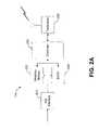
- a method for operating a brain implant systemcomprises: providing an electrode configured to be inserted in a brain and for sensing electrical signals generated by brain neurons; receiving the neuron electrical signals sensed by the electrode over a flexible wiring; receiving the neuron electrical signals from the flexible wiring and detecting the occurrence of a neuron spike in the received neuron electrical signals; and transmitting data reflecting the occurrence of each detected neuron spike.
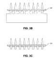
- FIGS. 3A to 3Dillustrate exemplary process for making an electrode array consistent with an embodiment of the present invention
- FIGS. 4A to 4Gillustrate an alternative, exemplary process for making an electrode array consistent with an embodiment of the present invention
- FIGS. 5A and 5Billustrate an exemplary wiring, consistent with an embodiment of the present invention, for attachment to an electrode array
- FIG. 6illustrates an exemplary method, consistent with an embodiment of the present invention, for connecting an electrode to a wiring.
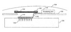
- Electrode array 110serves as the sensor for the brain implant system. While the various figures in this specification illustrate electrode array 110 as having sixty-four electrodes 112 arranged in an 8 ⁇ 8 matrix, array 110 may include one or more electrodes having a variety of sizes, lengths, shapes, forms, and arrangements. Each electrode 112 extends into brain 120 to detect the electrical neural signals generated from the neurons located in proximity to the electrode's placement within the brain. Neurons may generate such signals when, for example, the brain instructs a particular limb to move in a particular way. Electrode array 110 is described in more detail with respect to FIGS. 3A to 3D and FIGS. 4A to 4G .
- electrodes 112may have a variety of shapes, such as a continuous width shape (i.e., with no platform or stepped base section), a conical shape, a stepped-pyramidal shape, or a tapered shape different than that shown in FIG. 3A . Electrodes 112 may also have a variety of cross-sectional shapes, such as a rounded cross-section (which may be formed by a chemical etching process) or a rectangular, square, or hexagonal cross-section (which may be formed by the wire EDM technique). Moreover, as used herein, an electrode's “base section” refers broadly to the end portion of electrode 112 opposite the electrode's tip, without referring to the electrode's shape or width.
- each opening 420 in wiring 116may have a diameter sized to securely receive each electrode 112 , while compensating for any positional tolerances from a drilling or laser process when forming the holes.
Landscapes
- Life Sciences & Earth Sciences (AREA)
- Health & Medical Sciences (AREA)
- Medical Informatics (AREA)
- Biophysics (AREA)
- Pathology (AREA)
- Engineering & Computer Science (AREA)
- Biomedical Technology (AREA)
- Heart & Thoracic Surgery (AREA)
- Physics & Mathematics (AREA)
- Molecular Biology (AREA)
- Surgery (AREA)
- Animal Behavior & Ethology (AREA)
- General Health & Medical Sciences (AREA)
- Public Health (AREA)
- Veterinary Medicine (AREA)
- Measurement And Recording Of Electrical Phenomena And Electrical Characteristics Of The Living Body (AREA)
Abstract
Description
Claims (26)
Priority Applications (2)
| Application Number | Priority Date | Filing Date | Title |
|---|---|---|---|
| US10/278,853US7212851B2 (en) | 2002-10-24 | 2002-10-24 | Microstructured arrays for cortex interaction and related methods of manufacture and use |
| US11/723,999US20070169333A1 (en) | 2002-10-24 | 2007-03-23 | Microstructured arrays for cortex interaction and related methods of manufacture and use |
Applications Claiming Priority (1)
| Application Number | Priority Date | Filing Date | Title |
|---|---|---|---|
| US10/278,853US7212851B2 (en) | 2002-10-24 | 2002-10-24 | Microstructured arrays for cortex interaction and related methods of manufacture and use |
Related Child Applications (1)
| Application Number | Title | Priority Date | Filing Date |
|---|---|---|---|
| US11/723,999DivisionUS20070169333A1 (en) | 2002-10-24 | 2007-03-23 | Microstructured arrays for cortex interaction and related methods of manufacture and use |
Publications (2)
| Publication Number | Publication Date |
|---|---|
| US20040082875A1 US20040082875A1 (en) | 2004-04-29 |
| US7212851B2true US7212851B2 (en) | 2007-05-01 |
Family
ID=32106611
Family Applications (2)
| Application Number | Title | Priority Date | Filing Date |
|---|---|---|---|
| US10/278,853Expired - Fee RelatedUS7212851B2 (en) | 2002-10-24 | 2002-10-24 | Microstructured arrays for cortex interaction and related methods of manufacture and use |
| US11/723,999AbandonedUS20070169333A1 (en) | 2002-10-24 | 2007-03-23 | Microstructured arrays for cortex interaction and related methods of manufacture and use |
Family Applications After (1)
| Application Number | Title | Priority Date | Filing Date |
|---|---|---|---|
| US11/723,999AbandonedUS20070169333A1 (en) | 2002-10-24 | 2007-03-23 | Microstructured arrays for cortex interaction and related methods of manufacture and use |
Country Status (1)
| Country | Link |
|---|---|
| US (2) | US7212851B2 (en) |
Cited By (84)
| Publication number | Priority date | Publication date | Assignee | Title |
|---|---|---|---|---|
| US20060009814A1 (en)* | 2004-07-07 | 2006-01-12 | Alfred E. Mann Foundation For Scientific Research | Brian implant device |
| US20060129056A1 (en)* | 2004-12-10 | 2006-06-15 | Washington University | Electrocorticography telemitter |
| US20060149338A1 (en)* | 2005-01-06 | 2006-07-06 | Flaherty J C | Neurally controlled patient ambulation system |
| US20060224191A1 (en)* | 1998-08-05 | 2006-10-05 | Dilorenzo Daniel J | Systems and methods for monitoring a patient's neurological disease state |
| US20070067007A1 (en)* | 2005-05-25 | 2007-03-22 | Alfred E. Mann Foundation For Scientific Research | Hermetically sealed three-dimensional electrode array |
| US20070162086A1 (en)* | 1998-08-05 | 2007-07-12 | Bioneuronics Corporation | Monitoring efficacy of neural modulation therapy |
| US20070293749A1 (en)* | 2006-06-19 | 2007-12-20 | Zhou Dao M | Electrode with increased stability and method of manufacturing the same |
| US20080008626A1 (en)* | 2006-06-22 | 2008-01-10 | Chung Hua University | Microarray bioprobe device integrated with a semiconductor amplifier module on a flexible substrate |
| US20080027347A1 (en)* | 2006-06-23 | 2008-01-31 | Neuro Vista Corporation, A Delaware Corporation | Minimally Invasive Monitoring Methods |
| US20080057179A1 (en)* | 2005-04-28 | 2008-03-06 | Robert Greenberg | Flexible Circuit Electrode Array |
| US20080138581A1 (en)* | 2006-07-17 | 2008-06-12 | Rajmohan Bhandari | Masking high-aspect aspect ratio structures |
| US20080138583A1 (en)* | 2006-07-17 | 2008-06-12 | Rajmohan Bhandari | Micro-needle arrays having non-planar tips and methods of manufacture thereof |
| US20080183097A1 (en)* | 2007-01-25 | 2008-07-31 | Leyde Kent W | Methods and Systems for Measuring a Subject's Susceptibility to a Seizure |
| US20080183096A1 (en)* | 2007-01-25 | 2008-07-31 | David Snyder | Systems and Methods for Identifying a Contra-ictal Condition in a Subject |
| US20080234598A1 (en)* | 2007-03-21 | 2008-09-25 | David Snyder | Implantable Systems and Methods for Identifying a Contra-ictal Condition in a Subject |
| US20080297135A1 (en)* | 2007-06-04 | 2008-12-04 | Chung Hua University | Microarray bioprobe device integrated with an amplifier having bottom-gate thin film transistors |
| US20090018609A1 (en)* | 1998-08-05 | 2009-01-15 | Dilorenzo Daniel John | Closed-Loop Feedback-Driven Neuromodulation |
| US20090062682A1 (en)* | 2007-07-27 | 2009-03-05 | Michael Bland | Patient Advisory Device |
| US20090149913A1 (en)* | 2007-08-01 | 2009-06-11 | Putz David A | Wireless System for Epilepsy Monitoring and Measurement |
| US20090254146A1 (en)* | 2008-04-03 | 2009-10-08 | Giorgio Bonmassar | Deep brain stimulation implant with microcoil array |
| US20090301994A1 (en)* | 2008-05-12 | 2009-12-10 | Rajmohan Bhandari | Methods for Wafer Scale Processing of Needle Array Devices |
| US20100063411A1 (en)* | 2003-11-09 | 2010-03-11 | Cyberkinetics, Inc. | Calibration systems and methods for neural interface devices |
| US20100079156A1 (en)* | 2008-09-29 | 2010-04-01 | Chong Il Lee | Method and means for connecting a large number of electrodes to a measuring device |
| US7747325B2 (en) | 1998-08-05 | 2010-06-29 | Neurovista Corporation | Systems and methods for monitoring a patient's neurological disease state |
| US7881780B2 (en) | 2005-01-18 | 2011-02-01 | Braingate Co., Llc | Biological interface system with thresholded configuration |
| US20110125001A1 (en)* | 2009-11-25 | 2011-05-26 | Weileun Fang | 3d microelectrode structure and method for assembling the same |
| US7991461B2 (en) | 2005-01-06 | 2011-08-02 | Braingate Co., Llc | Patient training routine for biological interface system |
| US7991475B1 (en)* | 2005-06-08 | 2011-08-02 | The Regents Of The University Of California | High density micromachined electrode arrays useable for auditory nerve implants and related methods |
| US20110237921A1 (en)* | 2009-09-23 | 2011-09-29 | Ripple Llc | Systems and methods for flexible electrodes |
| US8095209B2 (en) | 2005-01-06 | 2012-01-10 | Braingate Co., Llc | Biological interface system with gated control signal |
| WO2012126003A1 (en) | 2011-03-17 | 2012-09-20 | Brown University | Implantable wireless neural device |
| US8295934B2 (en) | 2006-11-14 | 2012-10-23 | Neurovista Corporation | Systems and methods of reducing artifact in neurological stimulation systems |
| US20130157498A1 (en)* | 2011-11-11 | 2013-06-20 | Massachusetts Institute Of Technology | Methods and apparatus for three-dimensional microfabricated arrays |
| US20130207639A1 (en)* | 2012-02-10 | 2013-08-15 | California Institute Of Technology | Wireless voltage sensing device |
| US20130261490A1 (en)* | 2010-12-05 | 2013-10-03 | Wilson Truccolo | Methods for Prediction and Early Detection of Neurological Events |
| US8560041B2 (en) | 2004-10-04 | 2013-10-15 | Braingate Co., Llc | Biological interface system |
| US8588933B2 (en) | 2009-01-09 | 2013-11-19 | Cyberonics, Inc. | Medical lead termination sleeve for implantable medical devices |
| US8725243B2 (en) | 2005-12-28 | 2014-05-13 | Cyberonics, Inc. | Methods and systems for recommending an appropriate pharmacological treatment to a patient for managing epilepsy and other neurological disorders |
| US8738139B2 (en) | 2007-08-01 | 2014-05-27 | Bruce Lanning | Wireless system for epilepsy monitoring and measurement |
| US8762065B2 (en) | 1998-08-05 | 2014-06-24 | Cyberonics, Inc. | Closed-loop feedback-driven neuromodulation |
| US8774937B2 (en) | 2009-12-01 | 2014-07-08 | Ecole Polytechnique Federale De Lausanne | Microfabricated surface neurostimulation device and methods of making and using the same |
| US8788042B2 (en) | 2008-07-30 | 2014-07-22 | Ecole Polytechnique Federale De Lausanne (Epfl) | Apparatus and method for optimized stimulation of a neurological target |
| US8786624B2 (en) | 2009-06-02 | 2014-07-22 | Cyberonics, Inc. | Processing for multi-channel signals |
| US8788064B2 (en) | 2008-11-12 | 2014-07-22 | Ecole Polytechnique Federale De Lausanne | Microfabricated neurostimulation device |
| US8812096B2 (en) | 2005-01-10 | 2014-08-19 | Braingate Co., Llc | Biological interface system with patient training apparatus |
| US8849390B2 (en) | 2008-12-29 | 2014-09-30 | Cyberonics, Inc. | Processing for multi-channel signals |
| US8868172B2 (en) | 2005-12-28 | 2014-10-21 | Cyberonics, Inc. | Methods and systems for recommending an appropriate action to a patient for managing epilepsy and other neurological disorders |
| US8886279B2 (en) | 2008-06-03 | 2014-11-11 | University Of Utah Research Foundation | High aspect ratio microelectrode arrays enabled to have customizable lengths and methods of making the same |
| US9042988B2 (en) | 1998-08-05 | 2015-05-26 | Cyberonics, Inc. | Closed-loop vagus nerve stimulation |
| US9095267B2 (en) | 2011-12-22 | 2015-08-04 | Modular Bionics Inc. | Neural interface device and insertion tools |
| US20150305643A1 (en)* | 2014-03-24 | 2015-10-29 | University Of Utah Research Foundation | Neural interface |
| US9259591B2 (en) | 2007-12-28 | 2016-02-16 | Cyberonics, Inc. | Housing for an implantable medical device |
| US9403011B2 (en) | 2014-08-27 | 2016-08-02 | Aleva Neurotherapeutics | Leadless neurostimulator |
| US20160220135A1 (en)* | 2013-09-13 | 2016-08-04 | University Of Utah Research Foundation | Micro-molded electrodes, arrays, and methods of making the same |
| US9421373B2 (en) | 1998-08-05 | 2016-08-23 | Cyberonics, Inc. | Apparatus and method for closed-loop intracranial stimulation for optimal control of neurological disease |
| US9474894B2 (en) | 2014-08-27 | 2016-10-25 | Aleva Neurotherapeutics | Deep brain stimulation lead |
| US9549708B2 (en) | 2010-04-01 | 2017-01-24 | Ecole Polytechnique Federale De Lausanne | Device for interacting with neurological tissue and methods of making and using the same |
| US9643019B2 (en) | 2010-02-12 | 2017-05-09 | Cyberonics, Inc. | Neurological monitoring and alerts |
| US20170333700A1 (en)* | 2016-02-22 | 2017-11-23 | The Charles Stark Draper Laboratory, Inc. | Method of manufacturing an implantable neural electrode interface platform |
| US9849025B2 (en) | 2012-09-07 | 2017-12-26 | Yale University | Brain cooling system |
| US9925376B2 (en) | 2014-08-27 | 2018-03-27 | Aleva Neurotherapeutics | Treatment of autoimmune diseases with deep brain stimulation |
| US10086192B2 (en) | 2016-07-07 | 2018-10-02 | Modular Bionics Inc. | Neural interface insertion and retraction tools |
| US10674914B1 (en) | 2015-06-24 | 2020-06-09 | Modular Bionics Inc. | Wireless neural interface system |
| US10729564B2 (en) | 2018-01-12 | 2020-08-04 | Ripple Llc | Sensor system |
| US10966620B2 (en) | 2014-05-16 | 2021-04-06 | Aleva Neurotherapeutics Sa | Device for interacting with neurological tissue and methods of making and using the same |
| US20210198613A1 (en)* | 2018-09-05 | 2021-07-01 | Axosim, Inc. | Microelectrode array and uses thereof |
| US11065439B1 (en) | 2017-12-11 | 2021-07-20 | Modular Bionics Inc. | Conforming modular neural interface system |
| US11266830B2 (en) | 2018-03-02 | 2022-03-08 | Aleva Neurotherapeutics | Neurostimulation device |
| US11273283B2 (en) | 2017-12-31 | 2022-03-15 | Neuroenhancement Lab, LLC | Method and apparatus for neuroenhancement to enhance emotional response |
| US11311718B2 (en) | 2014-05-16 | 2022-04-26 | Aleva Neurotherapeutics Sa | Device for interacting with neurological tissue and methods of making and using the same |
| US11364361B2 (en) | 2018-04-20 | 2022-06-21 | Neuroenhancement Lab, LLC | System and method for inducing sleep by transplanting mental states |
| US11406317B2 (en) | 2007-12-28 | 2022-08-09 | Livanova Usa, Inc. | Method for detecting neurological and clinical manifestations of a seizure |
| US11452839B2 (en) | 2018-09-14 | 2022-09-27 | Neuroenhancement Lab, LLC | System and method of improving sleep |
| US11562907B2 (en) | 2018-11-29 | 2023-01-24 | International Business Machines Corporation | Nanostructure featuring nano-topography with optimized electrical and biochemical properties |
| US20230086004A1 (en)* | 2021-09-19 | 2023-03-23 | Zhi Yang | Artificial Intelligence Enabled Neuroprosthetic Hand |
| US11717686B2 (en) | 2017-12-04 | 2023-08-08 | Neuroenhancement Lab, LLC | Method and apparatus for neuroenhancement to facilitate learning and performance |
| US11723579B2 (en) | 2017-09-19 | 2023-08-15 | Neuroenhancement Lab, LLC | Method and apparatus for neuroenhancement |
| US11786694B2 (en) | 2019-05-24 | 2023-10-17 | NeuroLight, Inc. | Device, method, and app for facilitating sleep |
| US11959874B2 (en) | 2018-11-29 | 2024-04-16 | International Business Machines Corporation | Nanostructure featuring nano-topography with optimized electrical and biochemical properties |
| US12023162B2 (en) | 2018-11-29 | 2024-07-02 | International Business Machines Corporation | Three-dimensional silicon-based comb probe with optimized biocompatible dimensions for neural sensing and stimulation |
| US12035996B2 (en) | 2019-02-12 | 2024-07-16 | Brown University | High spatiotemporal resolution brain imaging |
| US12076110B2 (en) | 2021-10-20 | 2024-09-03 | Brown University | Large-scale wireless biosensor networks for biomedical diagnostics |
| US12280219B2 (en) | 2017-12-31 | 2025-04-22 | NeuroLight, Inc. | Method and apparatus for neuroenhancement to enhance emotional response |
| US12323714B2 (en) | 2022-04-20 | 2025-06-03 | Brown University | Compact optoelectronic device for noninvasive imaging |
Families Citing this family (60)
| Publication number | Priority date | Publication date | Assignee | Title |
|---|---|---|---|---|
| US7809432B2 (en)* | 2002-04-12 | 2010-10-05 | Infineon Technologies Ag | Event detection—apparatus and method for measuring the activity of neural networks |
| US7460904B2 (en)* | 2002-10-09 | 2008-12-02 | Wake Forest University Health Sciences | Wireless systems and methods for the detection of neural events using onboard processing |
| US9854985B2 (en)* | 2002-12-09 | 2018-01-02 | Bio-Signal Group Corp. | Brain signal telemetry and seizure prediction |
| US20040111043A1 (en)* | 2002-12-09 | 2004-06-10 | Bio-Signal Group Corp. | Bioelectric telemetering system and method for digital cable eliminator |
| US7187967B2 (en)* | 2003-09-30 | 2007-03-06 | Neural Signals, Inc. | Apparatus and method for detecting neural signals and using neural signals to drive external functions |
| US7187968B2 (en)* | 2003-10-23 | 2007-03-06 | Duke University | Apparatus for acquiring and transmitting neural signals and related methods |
| WO2005058135A2 (en)* | 2003-12-12 | 2005-06-30 | Washington University | Electrocorticography telemitter |
| US7120486B2 (en)* | 2003-12-12 | 2006-10-10 | Washington University | Brain computer interface |
| US8862235B1 (en)* | 2005-07-01 | 2014-10-14 | Alfred E. Mann Foundation For Scientific Research | Brain implant device |
| CN101124010B (en) | 2004-10-19 | 2012-09-26 | 国际复原科技公司(贸易用名Rs医药公司) | Method and means for electrical stimulation of cutaneous sensory receptors |
| US8417352B2 (en)* | 2004-10-19 | 2013-04-09 | Meagan Medical, Inc. | System and method for stimulating sensory nerves |
| US8068913B2 (en)* | 2004-12-03 | 2011-11-29 | Second Sight Medical Products, Inc. | Visual prosthesis for improved circadian rhythms and method of improving the circadian rhythms |
| US8485979B2 (en)* | 2004-12-17 | 2013-07-16 | Medtronic, Inc. | System and method for monitoring or treating nervous system disorders |
| US20060173261A1 (en)* | 2005-01-31 | 2006-08-03 | Magnus Kall | Biopotential sensor |
| US20060293578A1 (en)* | 2005-02-03 | 2006-12-28 | Rennaker Robert L Ii | Brian machine interface device |
| US20060264774A1 (en)* | 2005-08-25 | 2006-11-23 | Outland Research, Llc | Neurologically Controlled Access to an Electronic Information Resource |
| US20100168501A1 (en)* | 2006-10-02 | 2010-07-01 | Daniel Rogers Burnett | Method and apparatus for magnetic induction therapy |
| US9339641B2 (en) | 2006-01-17 | 2016-05-17 | Emkinetics, Inc. | Method and apparatus for transdermal stimulation over the palmar and plantar surfaces |
| US20070167990A1 (en)* | 2006-01-17 | 2007-07-19 | Theranova, Llc | Method and apparatus for low frequency induction therapy for the treatment of urinary incontinence and overactive bladder |
| US9610459B2 (en)* | 2009-07-24 | 2017-04-04 | Emkinetics, Inc. | Cooling systems and methods for conductive coils |
| DE102006008050A1 (en)* | 2006-02-21 | 2007-08-23 | Imi Intelligent Medical Implants Ag | Device with flexible multi layer system e.g. for contacting or electro stimulation of living tissue cells or nerves, has contact point for electrical contacting and PCB has structure of electrically isolating material layer |
| US9005102B2 (en) | 2006-10-02 | 2015-04-14 | Emkinetics, Inc. | Method and apparatus for electrical stimulation therapy |
| US11224742B2 (en) | 2006-10-02 | 2022-01-18 | Emkinetics, Inc. | Methods and devices for performing electrical stimulation to treat various conditions |
| US10786669B2 (en) | 2006-10-02 | 2020-09-29 | Emkinetics, Inc. | Method and apparatus for transdermal stimulation over the palmar and plantar surfaces |
| WO2008095108A1 (en)* | 2007-02-01 | 2008-08-07 | Ls Biopath, Inc. | Electrical systems for detection and characterization of abnormal tissue and cells |
| EP2174118A4 (en)* | 2007-02-01 | 2015-06-24 | Ls Biopath Inc | Optical system for identification and characterization of abnormal tissue and cells |
| US20080221645A1 (en)* | 2007-03-06 | 2008-09-11 | Neural Signals, Inc. | Neurotrophic Electrode Neural Interface Employing Quantum Dots |
| EP1985579B1 (en) | 2007-04-27 | 2018-01-10 | IMEC vzw | Connecting scheme for the orthogonal assembly of microstructures |
| US9521955B2 (en)* | 2007-05-03 | 2016-12-20 | Cornell Research Foundtion, Inc. | Subdural electro-optical sensor |
| US8380314B2 (en) | 2007-09-26 | 2013-02-19 | Medtronic, Inc. | Patient directed therapy control |
| US20090264789A1 (en)* | 2007-09-26 | 2009-10-22 | Medtronic, Inc. | Therapy program selection |
| WO2009051638A1 (en) | 2007-10-16 | 2009-04-23 | Medtronic, Inc. | Therapy control based on a patient movement state |
| US9072870B2 (en) | 2008-01-25 | 2015-07-07 | Medtronic, Inc. | Sleep stage detection |
| US8428732B2 (en)* | 2008-05-22 | 2013-04-23 | University Of Florida Research Foundation, Inc. | Neural interface systems and methods |
| FR2933621B1 (en)* | 2008-07-11 | 2010-09-10 | Commissariat Energie Atomique | IMPLANTABLE PROBE |
| JP5224482B2 (en)* | 2008-09-30 | 2013-07-03 | 国立大学法人 奈良先端科学技術大学院大学 | Brain information measuring device |
| CN101829396B (en)* | 2009-03-27 | 2013-01-30 | 清华大学 | Microneedle array chip, transdermal drug delivery patch using same and preparation method thereof |
| EP2493551A4 (en) | 2009-10-26 | 2013-04-17 | Emkinetics Inc | Method and apparatus for electromagnetic stimulation of nerve, muscle, and body tissues |
| US9770204B2 (en) | 2009-11-11 | 2017-09-26 | Medtronic, Inc. | Deep brain stimulation for sleep and movement disorders |
| US8588884B2 (en)* | 2010-05-28 | 2013-11-19 | Emkinetics, Inc. | Microneedle electrode |
| US8473072B2 (en) | 2010-06-08 | 2013-06-25 | Axelgaard Manufacturing Company, Ltd. | Customizable medical electrode |
| KR20120046554A (en)* | 2010-11-02 | 2012-05-10 | 연세대학교 산학협력단 | Sensor for detecting cancer tissue and manufacturing method of the same |
| WO2012158834A1 (en)* | 2011-05-16 | 2012-11-22 | Second Sight Medical Products, Inc. | Cortical interface with an electrode array divided into separate fingers and/or with a wireless transceiver |
| US9962546B2 (en) | 2013-02-21 | 2018-05-08 | Meagan Medical, Inc. | Cutaneous field stimulation with disposable and rechargeable components |
| US9386954B2 (en) | 2013-03-15 | 2016-07-12 | Zyvex Labs, Llc | Method of fabricating a multi-electrode array |
| CN103519808B (en)* | 2013-09-18 | 2015-04-22 | 电子科技大学 | Multi-channel microelectrode array and manufacturing method thereof |
| EP2870980B1 (en)* | 2013-11-08 | 2018-08-08 | NeuroNexus Technologies, Inc. | Three-dimensional neural probe microelectrode array |
| WO2015143443A1 (en) | 2014-03-21 | 2015-09-24 | University Of Utah Research Foundation | Multi-site electrode arrays and methods of making the same |
| GB2557612A (en)* | 2016-12-12 | 2018-06-27 | Kokoon Tech Ltd | Electroencephalography sensors |
| US12109032B1 (en) | 2017-03-11 | 2024-10-08 | Biolinq Incorporated | Methods for achieving an isolated electrical interface between an anterior surface of a microneedle structure and a posterior surface of a support structure |
| US11045142B1 (en)* | 2017-04-29 | 2021-06-29 | Biolinq, Inc. | Heterogeneous integration of silicon-fabricated solid microneedle sensors and CMOS circuitry |
| JP7032712B2 (en)* | 2018-01-31 | 2022-03-09 | 京セラ株式会社 | Ceramic guide, ceramic guide device and ceramic guide module |
| WO2019152648A1 (en)* | 2018-02-02 | 2019-08-08 | Carnegie Mellon University | 3d printed microelectrode arrays |
| GB2576502A (en)* | 2018-08-17 | 2020-02-26 | 3Brain Ag | Probe arrays |
| CN109350046A (en)* | 2018-09-07 | 2019-02-19 | 深圳市太空科技南方研究院 | A kind of flexible electrode and its manufacturing method |
| SE2251496A1 (en) | 2020-07-29 | 2022-12-20 | Biolinq Incorporated | Continuous analyte monitoring system with microneedle array |
| CA3184224A1 (en) | 2021-05-08 | 2022-11-17 | Joshua Ray Windmiller | Fault detection for microneedle array based continuous analyte monitoring device |
| CN114190948A (en)* | 2021-12-14 | 2022-03-18 | 深圳先进技术研究院 | A kind of long-term implantable multi-brain area recording electrode array fabrication method and using method |
| US12336816B2 (en) | 2023-02-02 | 2025-06-24 | Biolinq Incorporated | Method for improved sensor sensitivity of a microneedle-based continuous analyte monitoring system |
| WO2025035467A1 (en)* | 2023-08-17 | 2025-02-20 | 邢楚枫 | Implantation assistance apparatus |
Citations (104)
| Publication number | Priority date | Publication date | Assignee | Title |
|---|---|---|---|---|
| US3837339A (en) | 1972-02-03 | 1974-09-24 | Whittaker Corp | Blood glucose level monitoring-alarm system and method therefor |
| US3850161A (en) | 1973-04-09 | 1974-11-26 | S Liss | Method and apparatus for monitoring and counteracting excess brain electrical energy to prevent epileptic seizures and the like |
| US4055175A (en) | 1976-05-07 | 1977-10-25 | Miles Laboratories, Inc. | Blood glucose control apparatus |
| US4146029A (en) | 1974-04-23 | 1979-03-27 | Ellinwood Jr Everett H | Self-powered implanted programmable medication system and method |
| US4294245A (en) | 1980-03-24 | 1981-10-13 | Stimtech, Inc. | Perioperative application of electronic pain control in combination with anesthetic agents |
| US4360031A (en) | 1980-09-11 | 1982-11-23 | Medtronic, Inc. | Drug dispensing irrigatable electrode |
| US4461304A (en) | 1979-11-05 | 1984-07-24 | Massachusetts Institute Of Technology | Microelectrode and assembly for parallel recording of neurol groups |
| US4633889A (en) | 1984-12-12 | 1987-01-06 | Andrew Talalla | Stimulation of cauda-equina spinal nerves |
| US4690142A (en) | 1980-12-10 | 1987-09-01 | Ross Sidney A | Method and system for utilizing electro-neuro stimulation in a bio-feedback system |
| US4837049A (en) | 1986-06-17 | 1989-06-06 | Alfred E. Mann Foundation For Scientific Research | Method of making an electrode array |
| US4865048A (en) | 1987-12-31 | 1989-09-12 | Eckerson Harold D | Method and apparatus for drug free neurostimulation |
| US4878913A (en) | 1987-09-04 | 1989-11-07 | Pfizer Hospital Products Group, Inc. | Devices for neural signal transmission |
| US4883666A (en) | 1987-04-29 | 1989-11-28 | Massachusetts Institute Of Technology | Controlled drug delivery system for treatment of neural disorders |
| US4969468A (en) | 1986-06-17 | 1990-11-13 | Alfred E. Mann Foundation For Scientific Research | Electrode array for use in connection with a living body and method of manufacture |
| US5037376A (en) | 1988-07-22 | 1991-08-06 | The United States Of America As Represented By The Department Of Health And Human Services | Apparatus and method for transmitting prosthetic information to the brain |
| US5081990A (en) | 1990-05-11 | 1992-01-21 | New York University | Catheter for spinal epidural injection of drugs and measurement of evoked potentials |
| US5119832A (en) | 1989-07-11 | 1992-06-09 | Ravi Xavier | Epidural catheter with nerve stimulators |
| US5156844A (en) | 1987-11-17 | 1992-10-20 | Brown University Research Foundation | Neurological therapy system |
| US5215088A (en) | 1989-11-07 | 1993-06-01 | The University Of Utah | Three-dimensional electrode device |
| US5325865A (en) | 1990-02-26 | 1994-07-05 | Baxter International, Inc. | Intracranial pressure monitoring system |
| US5361760A (en) | 1989-11-07 | 1994-11-08 | University Of Utah Research Foundation | Impact inserter mechanism for implantation of a biomedical device |
| US5423877A (en) | 1992-05-04 | 1995-06-13 | David C. Mackey | Method and device for acute pain management by simultaneous spinal cord electrical stimulation and drug infusion |
| US5445608A (en) | 1993-08-16 | 1995-08-29 | James C. Chen | Method and apparatus for providing light-activated therapy |
| US5458631A (en) | 1989-01-06 | 1995-10-17 | Xavier; Ravi | Implantable catheter with electrical pulse nerve stimulators and drug delivery system |
| US5474547A (en) | 1989-06-21 | 1995-12-12 | Brown University Research Foundation | Implanting devices for the focal release of neuroinhibitory compounds |
| US5617871A (en) | 1993-11-02 | 1997-04-08 | Quinton Instrument Company | Spread spectrum telemetry of physiological signals |
| US5638826A (en) | 1995-06-01 | 1997-06-17 | Health Research, Inc. | Communication method and system using brain waves for multidimensional control |
| US5687291A (en) | 1996-06-27 | 1997-11-11 | The United States Of America As Represented By The Secretary Of The Army | Method and apparatus for estimating a cognitive decision made in response to a known stimulus from the corresponding single-event evoked cerebral potential |
| US5692517A (en) | 1993-01-06 | 1997-12-02 | Junker; Andrew | Brain-body actuated system |
| US5697951A (en) | 1996-04-25 | 1997-12-16 | Medtronic, Inc. | Implantable stimulation and drug infusion techniques |
| US5702432A (en) | 1996-10-03 | 1997-12-30 | Light Sciences Limited Partnership | Intracorporeal light treatment of blood |
| US5713923A (en) | 1996-05-13 | 1998-02-03 | Medtronic, Inc. | Techniques for treating epilepsy by brain stimulation and drug infusion |
| US5735885A (en) | 1994-02-09 | 1998-04-07 | The University Of Iowa Research Foundation | Methods for implanting neural prosthetic for tinnitus |
| US5758651A (en) | 1992-12-22 | 1998-06-02 | Nygard; Tony Mikeal | Telemetry system and apparatus |
| US5797898A (en) | 1996-07-02 | 1998-08-25 | Massachusetts Institute Of Technology | Microchip drug delivery devices |
| US5814089A (en) | 1996-12-18 | 1998-09-29 | Medtronic, Inc. | Leadless multisite implantable stimulus and diagnostic system |
| US5843093A (en) | 1994-02-09 | 1998-12-01 | University Of Iowa Research Foundation | Stereotactic electrode assembly |
| US5843142A (en) | 1997-03-27 | 1998-12-01 | Sultan; Hashem | Voice activated loco motor device and method of use for spinal cord injuries |
| US5855801A (en) | 1994-06-06 | 1999-01-05 | Lin; Liwei | IC-processed microneedles |
| US5873840A (en) | 1997-08-21 | 1999-02-23 | Neff; Samuel R. | Intracranial pressure monitoring system |
| US5928228A (en) | 1993-03-16 | 1999-07-27 | Ep Technologies, Inc. | Flexible high density multiple electrode circuit assemblies employing ribbon cable |
| US5938688A (en) | 1997-10-22 | 1999-08-17 | Cornell Research Foundation, Inc. | Deep brain stimulation method |
| US5938689A (en) | 1998-05-01 | 1999-08-17 | Neuropace, Inc. | Electrode configuration for a brain neuropacemaker |
| US5938690A (en) | 1996-06-07 | 1999-08-17 | Advanced Neuromodulation Systems, Inc. | Pain management system and method |
| US6001065A (en) | 1995-08-02 | 1999-12-14 | Ibva Technologies, Inc. | Method and apparatus for measuring and analyzing physiological signals for active or passive control of physical and virtual spaces and the contents therein |
| US6006124A (en) | 1998-05-01 | 1999-12-21 | Neuropace, Inc. | Means and method for the placement of brain electrodes |
| US6016449A (en) | 1997-10-27 | 2000-01-18 | Neuropace, Inc. | System for treatment of neurological disorders |
| US6024700A (en) | 1998-07-16 | 2000-02-15 | Nemirovski; Guerman G. | System and method for detecting a thought and generating a control instruction in response thereto |
| US6024702A (en) | 1997-09-03 | 2000-02-15 | Pmt Corporation | Implantable electrode manufactured with flexible printed circuit |
| US6027456A (en) | 1998-07-10 | 2000-02-22 | Advanced Neuromodulation Systems, Inc. | Apparatus and method for positioning spinal cord stimulation leads |
| US6038477A (en) | 1998-12-23 | 2000-03-14 | Axon Engineering, Inc. | Multiple channel nerve stimulator with channel isolation |
| US6086582A (en) | 1997-03-13 | 2000-07-11 | Altman; Peter A. | Cardiac drug delivery system |
| US6092058A (en) | 1998-01-08 | 2000-07-18 | The United States Of America As Represented By The Secretary Of The Army | Automatic aiding of human cognitive functions with computerized displays |
| US6091015A (en) | 1997-05-28 | 2000-07-18 | Universidad Politecnica De Cataluna | Photovoltaic energy supply system with optical fiber for implantable medical devices |
| US6094598A (en) | 1996-04-25 | 2000-07-25 | Medtronics, Inc. | Method of treating movement disorders by brain stimulation and drug infusion |
| US6113553A (en) | 1996-03-05 | 2000-09-05 | Lifesensors, Inc. | Telemetric intracranial pressure monitoring system |
| US6125300A (en) | 1998-09-11 | 2000-09-26 | Medtronic, Inc. | Implantable device with output circuitry for simultaneous stimulation at multiple sites |
| US6154678A (en) | 1999-03-19 | 2000-11-28 | Advanced Neuromodulation Systems, Inc. | Stimulation lead connector |
| US6161045A (en) | 1999-06-01 | 2000-12-12 | Neuropace, Inc. | Method for determining stimulation parameters for the treatment of epileptic seizures |
| US6163725A (en) | 1994-09-06 | 2000-12-19 | Case Western Reserve University | Functional neuromuscular stimulation system |
| US6169981B1 (en) | 1996-06-04 | 2001-01-02 | Paul J. Werbos | 3-brain architecture for an intelligent decision and control system |
| US6171239B1 (en)* | 1998-08-17 | 2001-01-09 | Emory University | Systems, methods, and devices for controlling external devices by signals derived directly from the nervous system |
| US6175762B1 (en) | 1996-04-10 | 2001-01-16 | University Of Technology, Sydney | EEG based activation system |
| US6181965B1 (en) | 1996-02-20 | 2001-01-30 | Advanced Bionics Corporation | Implantable microstimulator system for prevention of disorders |
| US6216045B1 (en) | 1999-04-26 | 2001-04-10 | Advanced Neuromodulation Systems, Inc. | Implantable lead and method of manufacture |
| US6224549B1 (en) | 1999-04-20 | 2001-05-01 | Nicolet Biomedical, Inc. | Medical signal monitoring and display |
| US6240315B1 (en) | 1998-02-25 | 2001-05-29 | Seung Kee Mo | Electrical apparatus for medical treatment using EMG envelope signal |
| WO2001043635A1 (en) | 1999-12-14 | 2001-06-21 | California Institute Of Technology | Neural prosthetic using temporal structure in the local field potential |
| US6263237B1 (en) | 1997-05-01 | 2001-07-17 | Medtronic, Inc. | Techniques for treating anxiety disorders by brain stimulation and drug infusion |
| US6280394B1 (en) | 1998-03-18 | 2001-08-28 | Sean R. Maloney | Apparatus and methods for detecting and processing EMG signals |
| US20010027336A1 (en) | 1998-01-20 | 2001-10-04 | Medtronic, Inc. | Combined micro-macro brain stimulation system |
| US20010029391A1 (en) | 1999-12-07 | 2001-10-11 | George Mason University | Adaptive electric field modulation of neural systems |
| US6309410B1 (en) | 1998-08-26 | 2001-10-30 | Advanced Bionics Corporation | Cochlear electrode with drug delivery channel and method of making same |
| US6313093B1 (en) | 1989-12-05 | 2001-11-06 | Chiron Corporation | Method for administering insulin to the brain |
| US6319241B1 (en) | 1998-04-30 | 2001-11-20 | Medtronic, Inc. | Techniques for positioning therapy delivery elements within a spinal cord or a brain |
| WO2001093756A2 (en) | 2000-06-09 | 2001-12-13 | Nexan Limited | Portable remote patient telemonitoring system using a memory card or smart card |
| US20010051819A1 (en) | 1997-10-27 | 2001-12-13 | Fischell Robert E. | Implantable apparatus for treating neurological disorders |
| US20010056290A1 (en) | 1997-10-27 | 2001-12-27 | Fischell Robert E. | Methods for responsively treating neurological disorders |
| WO2001060445A8 (en) | 2000-02-17 | 2002-01-03 | Neurodan As | Methods and implantable systems for neural sensing and nerve stimulation |
| US20020013612A1 (en) | 2000-06-20 | 2002-01-31 | Whitehurst Todd K. | System and method for treatment of mood and/or anxiety disorders by electrical brain stimulation and/or drug infusion |
| US6353754B1 (en) | 2000-04-24 | 2002-03-05 | Neuropace, Inc. | System for the creation of patient specific templates for epileptiform activity detection |
| US6354299B1 (en) | 1997-10-27 | 2002-03-12 | Neuropace, Inc. | Implantable device for patient communication |
| US6356784B1 (en) | 1999-04-30 | 2002-03-12 | Medtronic, Inc. | Method of treating movement disorders by electrical stimulation and/or drug infusion of the pendunulopontine nucleus |
| US6358202B1 (en) | 1999-01-25 | 2002-03-19 | Sun Microsystems, Inc. | Network for implanted computer devices |
| US6366813B1 (en) | 1998-08-05 | 2002-04-02 | Dilorenzo Daniel J. | Apparatus and method for closed-loop intracranical stimulation for optimal control of neurological disease |
| US20020077620A1 (en) | 2000-12-18 | 2002-06-20 | Sweeney Robert J. | Drug delivery system for implantable medical device |
| US6427086B1 (en) | 1997-10-27 | 2002-07-30 | Neuropace, Inc. | Means and method for the intracranial placement of a neurostimulator |
| US6436708B1 (en) | 1997-04-17 | 2002-08-20 | Paola Leone | Delivery system for gene therapy to the brain |
| US6466822B1 (en) | 2000-04-05 | 2002-10-15 | Neuropace, Inc. | Multimodal neurostimulator and process of using it |
| US6473639B1 (en) | 2000-03-02 | 2002-10-29 | Neuropace, Inc. | Neurological event detection procedure using processed display channel based algorithms and devices incorporating these procedures |
| US6480743B1 (en) | 2000-04-05 | 2002-11-12 | Neuropace, Inc. | System and method for adaptive brain stimulation |
| US20020169485A1 (en) | 1995-10-16 | 2002-11-14 | Neuropace, Inc. | Differential neurostimulation therapy driven by physiological context |
| WO2002093312A2 (en) | 2001-05-15 | 2002-11-21 | Hill-Rom Services, Inc. | Apparatus and method for patient data management |
| WO2002100267A1 (en) | 2001-06-13 | 2002-12-19 | Compumedics Limited | Methods and apparatus for monitoring consciousness |
| US20030004428A1 (en) | 2001-06-28 | 2003-01-02 | Pless Benjamin D. | Seizure sensing and detection using an implantable device |
| US20030083716A1 (en) | 2001-10-23 | 2003-05-01 | Nicolelis Miguel A.L. | Intelligent brain pacemaker for real-time monitoring and controlling of epileptic seizures |
| US20030083724A1 (en) | 2001-10-31 | 2003-05-01 | Mandar Jog | Multichannel electrode and methods of using same |
| US20030082507A1 (en) | 2001-10-31 | 2003-05-01 | Stypulkowski Paul H. | System and method of treating stuttering by neuromodulation |
| US20030093129A1 (en) | 2001-10-29 | 2003-05-15 | Nicolelis Miguel A.L. | Closed loop brain machine interface |
| US6577893B1 (en) | 1993-09-04 | 2003-06-10 | Motorola, Inc. | Wireless medical diagnosis and monitoring equipment |
| WO2003061465A2 (en) | 2002-01-22 | 2003-07-31 | Gmp Wireless Medicine, Inc. | Wireless ecg system |
| US6620415B2 (en) | 2000-06-14 | 2003-09-16 | Allergan, Inc. | Parkinson's disease treatment |
| US20040006264A1 (en)* | 2001-11-20 | 2004-01-08 | Mojarradi Mohammad M. | Neural prosthetic micro system |
| US20040138579A1 (en)* | 2002-10-09 | 2004-07-15 | Deadwyler Sam A. | Wireless systems and methods for the detection of neural events using onboard processing |
Family Cites Families (2)
| Publication number | Priority date | Publication date | Assignee | Title |
|---|---|---|---|---|
| DE3727505C2 (en)* | 1986-09-09 | 1996-10-10 | Campagnolo Spa | Gear selector for a bicycle gear shift |
| US5388577A (en)* | 1990-06-08 | 1995-02-14 | Boston University | Electrode array microchip |
- 2002
- 2002-10-24USUS10/278,853patent/US7212851B2/ennot_activeExpired - Fee Related
- 2007
- 2007-03-23USUS11/723,999patent/US20070169333A1/ennot_activeAbandoned
Patent Citations (116)
| Publication number | Priority date | Publication date | Assignee | Title |
|---|---|---|---|---|
| US3837339A (en) | 1972-02-03 | 1974-09-24 | Whittaker Corp | Blood glucose level monitoring-alarm system and method therefor |
| US3850161A (en) | 1973-04-09 | 1974-11-26 | S Liss | Method and apparatus for monitoring and counteracting excess brain electrical energy to prevent epileptic seizures and the like |
| US4146029A (en) | 1974-04-23 | 1979-03-27 | Ellinwood Jr Everett H | Self-powered implanted programmable medication system and method |
| US4055175A (en) | 1976-05-07 | 1977-10-25 | Miles Laboratories, Inc. | Blood glucose control apparatus |
| US4461304A (en) | 1979-11-05 | 1984-07-24 | Massachusetts Institute Of Technology | Microelectrode and assembly for parallel recording of neurol groups |
| US4294245A (en) | 1980-03-24 | 1981-10-13 | Stimtech, Inc. | Perioperative application of electronic pain control in combination with anesthetic agents |
| US4360031A (en) | 1980-09-11 | 1982-11-23 | Medtronic, Inc. | Drug dispensing irrigatable electrode |
| US4690142A (en) | 1980-12-10 | 1987-09-01 | Ross Sidney A | Method and system for utilizing electro-neuro stimulation in a bio-feedback system |
| US4633889A (en) | 1984-12-12 | 1987-01-06 | Andrew Talalla | Stimulation of cauda-equina spinal nerves |
| US4837049A (en) | 1986-06-17 | 1989-06-06 | Alfred E. Mann Foundation For Scientific Research | Method of making an electrode array |
| US4969468A (en) | 1986-06-17 | 1990-11-13 | Alfred E. Mann Foundation For Scientific Research | Electrode array for use in connection with a living body and method of manufacture |
| US4883666A (en) | 1987-04-29 | 1989-11-28 | Massachusetts Institute Of Technology | Controlled drug delivery system for treatment of neural disorders |
| US4878913A (en) | 1987-09-04 | 1989-11-07 | Pfizer Hospital Products Group, Inc. | Devices for neural signal transmission |
| US5156844A (en) | 1987-11-17 | 1992-10-20 | Brown University Research Foundation | Neurological therapy system |
| US4865048A (en) | 1987-12-31 | 1989-09-12 | Eckerson Harold D | Method and apparatus for drug free neurostimulation |
| US5037376A (en) | 1988-07-22 | 1991-08-06 | The United States Of America As Represented By The Department Of Health And Human Services | Apparatus and method for transmitting prosthetic information to the brain |
| US5458631A (en) | 1989-01-06 | 1995-10-17 | Xavier; Ravi | Implantable catheter with electrical pulse nerve stimulators and drug delivery system |
| US5474547A (en) | 1989-06-21 | 1995-12-12 | Brown University Research Foundation | Implanting devices for the focal release of neuroinhibitory compounds |
| US5119832A (en) | 1989-07-11 | 1992-06-09 | Ravi Xavier | Epidural catheter with nerve stimulators |
| US5361760A (en) | 1989-11-07 | 1994-11-08 | University Of Utah Research Foundation | Impact inserter mechanism for implantation of a biomedical device |
| US5215088A (en) | 1989-11-07 | 1993-06-01 | The University Of Utah | Three-dimensional electrode device |
| US6313093B1 (en) | 1989-12-05 | 2001-11-06 | Chiron Corporation | Method for administering insulin to the brain |
| US5325865A (en) | 1990-02-26 | 1994-07-05 | Baxter International, Inc. | Intracranial pressure monitoring system |
| US5081990A (en) | 1990-05-11 | 1992-01-21 | New York University | Catheter for spinal epidural injection of drugs and measurement of evoked potentials |
| US5423877A (en) | 1992-05-04 | 1995-06-13 | David C. Mackey | Method and device for acute pain management by simultaneous spinal cord electrical stimulation and drug infusion |
| US5758651A (en) | 1992-12-22 | 1998-06-02 | Nygard; Tony Mikeal | Telemetry system and apparatus |
| US5692517A (en) | 1993-01-06 | 1997-12-02 | Junker; Andrew | Brain-body actuated system |
| US5928228A (en) | 1993-03-16 | 1999-07-27 | Ep Technologies, Inc. | Flexible high density multiple electrode circuit assemblies employing ribbon cable |
| US5445608A (en) | 1993-08-16 | 1995-08-29 | James C. Chen | Method and apparatus for providing light-activated therapy |
| US6577893B1 (en) | 1993-09-04 | 2003-06-10 | Motorola, Inc. | Wireless medical diagnosis and monitoring equipment |
| US5617871A (en) | 1993-11-02 | 1997-04-08 | Quinton Instrument Company | Spread spectrum telemetry of physiological signals |
| US5735885A (en) | 1994-02-09 | 1998-04-07 | The University Of Iowa Research Foundation | Methods for implanting neural prosthetic for tinnitus |
| US5843093A (en) | 1994-02-09 | 1998-12-01 | University Of Iowa Research Foundation | Stereotactic electrode assembly |
| US5855801A (en) | 1994-06-06 | 1999-01-05 | Lin; Liwei | IC-processed microneedles |
| US6163725A (en) | 1994-09-06 | 2000-12-19 | Case Western Reserve University | Functional neuromuscular stimulation system |
| US5638826A (en) | 1995-06-01 | 1997-06-17 | Health Research, Inc. | Communication method and system using brain waves for multidimensional control |
| US6254536B1 (en) | 1995-08-02 | 2001-07-03 | Ibva Technologies, Inc. | Method and apparatus for measuring and analyzing physiological signals for active or passive control of physical and virtual spaces and the contents therein |
| US6001065A (en) | 1995-08-02 | 1999-12-14 | Ibva Technologies, Inc. | Method and apparatus for measuring and analyzing physiological signals for active or passive control of physical and virtual spaces and the contents therein |
| US20020169485A1 (en) | 1995-10-16 | 2002-11-14 | Neuropace, Inc. | Differential neurostimulation therapy driven by physiological context |
| US6181965B1 (en) | 1996-02-20 | 2001-01-30 | Advanced Bionics Corporation | Implantable microstimulator system for prevention of disorders |
| US6185455B1 (en) | 1996-02-20 | 2001-02-06 | Advanced Bionics Corporation | Method of reducing the incidence of medical complications using implantable microstimulators |
| US6113553A (en) | 1996-03-05 | 2000-09-05 | Lifesensors, Inc. | Telemetric intracranial pressure monitoring system |
| US6175762B1 (en) | 1996-04-10 | 2001-01-16 | University Of Technology, Sydney | EEG based activation system |
| US6094598A (en) | 1996-04-25 | 2000-07-25 | Medtronics, Inc. | Method of treating movement disorders by brain stimulation and drug infusion |
| US5697951A (en) | 1996-04-25 | 1997-12-16 | Medtronic, Inc. | Implantable stimulation and drug infusion techniques |
| US5713923A (en) | 1996-05-13 | 1998-02-03 | Medtronic, Inc. | Techniques for treating epilepsy by brain stimulation and drug infusion |
| US6169981B1 (en) | 1996-06-04 | 2001-01-02 | Paul J. Werbos | 3-brain architecture for an intelligent decision and control system |
| US5938690A (en) | 1996-06-07 | 1999-08-17 | Advanced Neuromodulation Systems, Inc. | Pain management system and method |
| US5687291A (en) | 1996-06-27 | 1997-11-11 | The United States Of America As Represented By The Secretary Of The Army | Method and apparatus for estimating a cognitive decision made in response to a known stimulus from the corresponding single-event evoked cerebral potential |
| US5797898A (en) | 1996-07-02 | 1998-08-25 | Massachusetts Institute Of Technology | Microchip drug delivery devices |
| US5702432A (en) | 1996-10-03 | 1997-12-30 | Light Sciences Limited Partnership | Intracorporeal light treatment of blood |
| US5814089A (en) | 1996-12-18 | 1998-09-29 | Medtronic, Inc. | Leadless multisite implantable stimulus and diagnostic system |
| US6086582A (en) | 1997-03-13 | 2000-07-11 | Altman; Peter A. | Cardiac drug delivery system |
| US5843142A (en) | 1997-03-27 | 1998-12-01 | Sultan; Hashem | Voice activated loco motor device and method of use for spinal cord injuries |
| US6436708B1 (en) | 1997-04-17 | 2002-08-20 | Paola Leone | Delivery system for gene therapy to the brain |
| US6263237B1 (en) | 1997-05-01 | 2001-07-17 | Medtronic, Inc. | Techniques for treating anxiety disorders by brain stimulation and drug infusion |
| US6091015A (en) | 1997-05-28 | 2000-07-18 | Universidad Politecnica De Cataluna | Photovoltaic energy supply system with optical fiber for implantable medical devices |
| US5873840A (en) | 1997-08-21 | 1999-02-23 | Neff; Samuel R. | Intracranial pressure monitoring system |
| US6024702A (en) | 1997-09-03 | 2000-02-15 | Pmt Corporation | Implantable electrode manufactured with flexible printed circuit |
| US5938688A (en) | 1997-10-22 | 1999-08-17 | Cornell Research Foundation, Inc. | Deep brain stimulation method |
| US6134474A (en) | 1997-10-27 | 2000-10-17 | Neuropace, Inc. | Responsive implantable system for the treatment of neurological disorders |
| US6360122B1 (en) | 1997-10-27 | 2002-03-19 | Neuropace, Inc. | Data recording methods for an implantable device |
| US6459936B2 (en) | 1997-10-27 | 2002-10-01 | Neuropace, Inc. | Methods for responsively treating neurological disorders |
| US6128538A (en) | 1997-10-27 | 2000-10-03 | Neuropace, Inc. | Means and method for the treatment of neurological disorders |
| US6016449A (en) | 1997-10-27 | 2000-01-18 | Neuropace, Inc. | System for treatment of neurological disorders |
| US6427086B1 (en) | 1997-10-27 | 2002-07-30 | Neuropace, Inc. | Means and method for the intracranial placement of a neurostimulator |
| US20010051819A1 (en) | 1997-10-27 | 2001-12-13 | Fischell Robert E. | Implantable apparatus for treating neurological disorders |
| US6061593A (en) | 1997-10-27 | 2000-05-09 | Neuropace, Inc. | EEG d-c voltage shift as a means for detecting the onset of a neurological event |
| US20020099412A1 (en) | 1997-10-27 | 2002-07-25 | Neuropace, Inc. | Methods for using an implantable device for patient communication |
| US20010056290A1 (en) | 1997-10-27 | 2001-12-27 | Fischell Robert E. | Methods for responsively treating neurological disorders |
| US20020002390A1 (en) | 1997-10-27 | 2002-01-03 | Fischell Robert E. | Implantable neurostimulator having a data communication link |
| US6354299B1 (en) | 1997-10-27 | 2002-03-12 | Neuropace, Inc. | Implantable device for patient communication |
| US6092058A (en) | 1998-01-08 | 2000-07-18 | The United States Of America As Represented By The Secretary Of The Army | Automatic aiding of human cognitive functions with computerized displays |
| US20010027336A1 (en) | 1998-01-20 | 2001-10-04 | Medtronic, Inc. | Combined micro-macro brain stimulation system |
| US6240315B1 (en) | 1998-02-25 | 2001-05-29 | Seung Kee Mo | Electrical apparatus for medical treatment using EMG envelope signal |
| US6280394B1 (en) | 1998-03-18 | 2001-08-28 | Sean R. Maloney | Apparatus and methods for detecting and processing EMG signals |
| US6319241B1 (en) | 1998-04-30 | 2001-11-20 | Medtronic, Inc. | Techniques for positioning therapy delivery elements within a spinal cord or a brain |
| US6006124A (en) | 1998-05-01 | 1999-12-21 | Neuropace, Inc. | Means and method for the placement of brain electrodes |
| US5938689A (en) | 1998-05-01 | 1999-08-17 | Neuropace, Inc. | Electrode configuration for a brain neuropacemaker |
| US6027456A (en) | 1998-07-10 | 2000-02-22 | Advanced Neuromodulation Systems, Inc. | Apparatus and method for positioning spinal cord stimulation leads |
| US6024700A (en) | 1998-07-16 | 2000-02-15 | Nemirovski; Guerman G. | System and method for detecting a thought and generating a control instruction in response thereto |
| US6366813B1 (en) | 1998-08-05 | 2002-04-02 | Dilorenzo Daniel J. | Apparatus and method for closed-loop intracranical stimulation for optimal control of neurological disease |
| US6171239B1 (en)* | 1998-08-17 | 2001-01-09 | Emory University | Systems, methods, and devices for controlling external devices by signals derived directly from the nervous system |
| US6309410B1 (en) | 1998-08-26 | 2001-10-30 | Advanced Bionics Corporation | Cochlear electrode with drug delivery channel and method of making same |
| US6125300A (en) | 1998-09-11 | 2000-09-26 | Medtronic, Inc. | Implantable device with output circuitry for simultaneous stimulation at multiple sites |
| US6038477A (en) | 1998-12-23 | 2000-03-14 | Axon Engineering, Inc. | Multiple channel nerve stimulator with channel isolation |
| US6358202B1 (en) | 1999-01-25 | 2002-03-19 | Sun Microsystems, Inc. | Network for implanted computer devices |
| US6154678A (en) | 1999-03-19 | 2000-11-28 | Advanced Neuromodulation Systems, Inc. | Stimulation lead connector |
| US6224549B1 (en) | 1999-04-20 | 2001-05-01 | Nicolet Biomedical, Inc. | Medical signal monitoring and display |
| US20010023368A1 (en) | 1999-04-26 | 2001-09-20 | Advanced Neuromodulation Systems, Inc. | Implantable lead and method of manufacture |
| US6216045B1 (en) | 1999-04-26 | 2001-04-10 | Advanced Neuromodulation Systems, Inc. | Implantable lead and method of manufacture |
| US6356784B1 (en) | 1999-04-30 | 2002-03-12 | Medtronic, Inc. | Method of treating movement disorders by electrical stimulation and/or drug infusion of the pendunulopontine nucleus |
| US6161045A (en) | 1999-06-01 | 2000-12-12 | Neuropace, Inc. | Method for determining stimulation parameters for the treatment of epileptic seizures |
| US20010029391A1 (en) | 1999-12-07 | 2001-10-11 | George Mason University | Adaptive electric field modulation of neural systems |
| WO2001043635A1 (en) | 1999-12-14 | 2001-06-21 | California Institute Of Technology | Neural prosthetic using temporal structure in the local field potential |
| US20020016638A1 (en) | 1999-12-14 | 2002-02-07 | Partha Mitra | Neural prosthetic using temporal structure in the local field potential |
| US6920351B2 (en)* | 1999-12-14 | 2005-07-19 | California Institute Of Technology | Neural prosthetic using temporal structure in the local field potential |
| WO2001060445A8 (en) | 2000-02-17 | 2002-01-03 | Neurodan As | Methods and implantable systems for neural sensing and nerve stimulation |
| US6473639B1 (en) | 2000-03-02 | 2002-10-29 | Neuropace, Inc. | Neurological event detection procedure using processed display channel based algorithms and devices incorporating these procedures |
| US6466822B1 (en) | 2000-04-05 | 2002-10-15 | Neuropace, Inc. | Multimodal neurostimulator and process of using it |
| US6480743B1 (en) | 2000-04-05 | 2002-11-12 | Neuropace, Inc. | System and method for adaptive brain stimulation |
| US6353754B1 (en) | 2000-04-24 | 2002-03-05 | Neuropace, Inc. | System for the creation of patient specific templates for epileptiform activity detection |
| WO2001093756A2 (en) | 2000-06-09 | 2001-12-13 | Nexan Limited | Portable remote patient telemonitoring system using a memory card or smart card |
| US6620415B2 (en) | 2000-06-14 | 2003-09-16 | Allergan, Inc. | Parkinson's disease treatment |
| US20020013612A1 (en) | 2000-06-20 | 2002-01-31 | Whitehurst Todd K. | System and method for treatment of mood and/or anxiety disorders by electrical brain stimulation and/or drug infusion |
| US20020077620A1 (en) | 2000-12-18 | 2002-06-20 | Sweeney Robert J. | Drug delivery system for implantable medical device |
| WO2002093312A2 (en) | 2001-05-15 | 2002-11-21 | Hill-Rom Services, Inc. | Apparatus and method for patient data management |
| WO2002100267A1 (en) | 2001-06-13 | 2002-12-19 | Compumedics Limited | Methods and apparatus for monitoring consciousness |
| US20030004428A1 (en) | 2001-06-28 | 2003-01-02 | Pless Benjamin D. | Seizure sensing and detection using an implantable device |
| US20030083716A1 (en) | 2001-10-23 | 2003-05-01 | Nicolelis Miguel A.L. | Intelligent brain pacemaker for real-time monitoring and controlling of epileptic seizures |
| US20030093129A1 (en) | 2001-10-29 | 2003-05-15 | Nicolelis Miguel A.L. | Closed loop brain machine interface |
| US20030082507A1 (en) | 2001-10-31 | 2003-05-01 | Stypulkowski Paul H. | System and method of treating stuttering by neuromodulation |
| US20030083724A1 (en) | 2001-10-31 | 2003-05-01 | Mandar Jog | Multichannel electrode and methods of using same |
| US20040006264A1 (en)* | 2001-11-20 | 2004-01-08 | Mojarradi Mohammad M. | Neural prosthetic micro system |
| WO2003061465A2 (en) | 2002-01-22 | 2003-07-31 | Gmp Wireless Medicine, Inc. | Wireless ecg system |
| US20040138579A1 (en)* | 2002-10-09 | 2004-07-15 | Deadwyler Sam A. | Wireless systems and methods for the detection of neural events using onboard processing |
Non-Patent Citations (92)
| Title |
|---|
| A. Bohg, "Ethylene Diamine-Pyrocatechol-Water Mixture Shows Etching Anomaly in Boron-Doped Silicon," Journal of the Electrochemical Society, vol. 118, No. 2, Feb. 1971, pp. 401-402. |
| A. C. Hoogerwerf et al., "A Three-Dimensional Neural Recording Array," IEEE Transactions, 1991, pp. 120-123. |
| A. J. S. Summerlee et al., "The effect of behavioural arousal on the activity of hypothalamic neurons in unanaesthetized, freely moving rats and rabbits," Proceedings of the Royal Society of London Series B-Biological Sciences, Jan. 1982, pp. 263-272. |
| Andrew B. Schwartz et al., "Extraction algorithms for cortical control of arm prosthetics," The Neuroscience Institute; and Department of Bioengineering, Arizona State Univeristy, 2001, pp. 701-707. |
| Andrew R. Mitz et al., "Learning-dependent Neuronal Activity in the Premotor Cortex: Activity during the Acquisition of Conditional Motor Associations," The Journal of Neuroscience, vol. 11, No. 6, Jun. 1991, pp. 1855-1872. |
| Anthony L. Owens et al., "Multi-electrode array for measuring evoked potentials from surface of ferret primary auditory cortex," Journal of Neuroscience Methods, vol. 58, Nos. 1/2, May 1995, pp. 209-220. |
| Apostolos P. Georgopoulos et al., "Neuronal Population Coding of Movement Direction," Science, vol. 233, Sep. 26, 1986, pp. 1416-1419. |
| Arnold C. Hoogerwerf et al., "A Three-Dimensional Microelectrode Array for Chronic Neural Recording," IEEE Transactions on Biomedical Engineering, vol. 41, No. 12, Dec. 1994, pp. 1136-1146. |
| Arnold Starr et al., "An Evaluation of Photoengraved Microelectrodes for Extracellular Single-Unit Recording," IEEE Transactions on Biomedical Engineering, vol. BME-20, No. 4, Jul. 1973, pp. 291-293. |
| Barbara M. Faggin et al., "Immediate and simultaneous sensory reorganization at cortical and subcortical levels of the somatosensory system," Proc. Natl. Acad. Science USA, vol. 94, Aug. 1997, pp. 9428-9433. |
| Camilo Toro et al., "8-12 Hz rhythmic oscillations in human motor cortex during two-dimensional arm movements: evidence for representation of kinermatic parameters," Departments Neurology, Neurosurgery, and Physiology, University of Minnesota; MINCEP Epilepsy Care, P.A.; The Minnesota Epilepsy Group of United and St. Paul Children's Hospital; and Human Motor Control Section, National Institue of Neurological Disorders and Stroke, National Institutes of Health, Electroencephalography and Clinical Neurophysiology, No. 93, 1994, pp. 390-403. |
| Changhyun Kim et al., "A 64-Site Multishank CMOS Low-Profile Neural Stimulating Probe," IEEE Journal of Solid-State Circuits, vol. 31, No. 9, Sep. 1996, pp. 1230-1238. |
| Craig T. Nordhausen et al., "Optimizing recoding capabilities of the Utah Intracortical Electrode Array," Brain Research, vol. 637, Nos. 1/2, Feb. 21, 1994, pp. 27-36. |
| D. Gareth Evans et al., "Controlling Mouse Pointer Position Using an Infrared Head-Operated Joystick," IEEE Transactions on Rehabilitation Engineering, vol. 8, No. 1, Mar. 2000, pp. 107-117. |
| D. M. Halliday et al., "A Framework for the Analysis of Mixed Time Series/Point Process Data-Theory and Application to the Study of Physiological Tremor, Single Motor Unit Discharges and Electromyograms," Progress in Biophysics Molecular Biology, vol. 64, Nos. 2/3, 1995, pp. 237-278. |
| David K. Warland et al., "Decoding Visual Information From a Population of Retinal Ganglion Cells," The American Physiological Society, 1997, pp. 2336-2350. |
| David L. Zealear et al., "The Biocompatabilty, Integrity, and Positional Stability of an Injectable Microstimulator for Reanimation of the Paralyzed Larynx," IEEE Transactions on Biomedical Engineering, vol. 48, No. 8, Aug. 2001, pp. 890-897. |
| Dawn M. Taylor et al., "Direct Cortical Control of 3D Neuroprosthetic Devices," Science, vol. 296, Jun. 7, 2002, pp. 1829-1832. |
| Dawn M. Taylor et al., "Using Virtual Reality to Test the Feasibility of Controlling an Upper Limb Fes System Directly from Multiunit Activity in the Motor Cortex," Arizona State University; and The Neurosciences Institute, Summer 2001, pp. 1-3. |
| Donald R. Humphrey et al., "Predicting Measures of Motor Performance from Multiple Cortical Spike Trains," Science, New Series, vol. 170, Issue 3959, Nov. 13, 1970, pp. 758-762. |
| Donald R. Humphrey, "Relating Motor Cortex Spike Trains to Measures of Motor Performance," Department of Physiology, Emory University, Brain Research, No. 40, 1972, pp. 7-18. |
| E. M. Maynard et al., "Neuronal Interactions Improve Cortical Population Coding of Movement Direction," The Journal of Neuroscience, vol. 19, No. 18, Sep. 15, 1999, pp. 8083-8093. |
| Edward M. Schmidt, "Single Neuron Recording From Motor Cortex as a Possible Source of Signals for Control of External Devices," Annals of Biochemical Engineering, vol. 8, 1980, pp. 339-349. |
| F. Gandolfo et al., "Cortical correlates of learning in monkeys adapting to a new dynamical environment," PNAS, vol. 97, No. 5, Feb. 29, 2000, pp. 2259-2263. |
| Frank Wood et al., "On the Variability of Manual Spike Sorting," Brown University, Providence, RI, Jul. 1, 2003, pp. 1-19. |
| Gerald E. Loeb et al., "BION(TM) system for distributed neural prosthetic interfaces," Medical Engineering & Physics, vol. 23, Jan. 26, 2001, pp. 9-18. |
| Gerald E. Loeb et al., "BION™ system for distributed neural prosthetic interfaces," Medical Engineering & Physics, vol. 23, Jan. 26, 2001, pp. 9-18. |
| Gregor Rainer et al., "Prospective Coding for Objects in Primate Prefontal Cortex," The Journal of Neuroscience, vol. 19, No. 13, Jul. 1, 1999, pp. 5493-5505. |
| Gregory T. A. Kovacs et al., "Regeneration Microelectrode Array for Peripheral Nerve Recording and Stimulation," Transactions on Biomedical Engineering, vol. 39, No. 9, Sep. 1992, pp. 893-902. |
| Gwo-Ching Chang et al., "Real-time implementation of electromyogram pattern recognition as a control command of man-machine interface," Medical Engineering Phys., vol. 18, No. 7, 1996, pp. 529-537. |
| International Publication No. WO 03/035165, May 1, 2003, Nicolelis et al. |
| International Publication No. WO 03/037231, May 8, 2003, Nicolelis et al. |
| István Ulbert et al., "Multiple microelectrode-recording system for human intracortical applications," Journal of Neuroscience Methods, vol. 106, 2001, pp. 69-79. |
| J. F. Marsden et al., "Organization of Cortical Activities Related to Movement in Humans," The Journal of Neuroscience, vol. 20, No. 6, Mar. 15, 2000, pp. 2307-2314. |
| Jamille F. Hetke et al., "Silicon Ribbon Cables for Chronically Implantable Microelectrode Arrays," IEEE Transactions on Biomedical Engineering, vol. 41, No. 4, Apr. 1994, pp. 314-321. |
| Jerome N. Sanes et al., "Plasticity and Primary Motor Cortex," Annual Reviews, Neuroscience, Brown University Library, vol. 23, 2000, pp. 393-415. |
| Jerome N. Sanes et al., "Shared Neural Substrates Controlling Hand Movements in Human Motor Cortex," Science, vol. 268, Jun. 23, 1995, pp. 1775-1777. |
| Johan Wessberg et al., "Real-time predicton of hand trajectory by ensembles of cortical neurons in primates," Nature, vol. 408, Nov. 16, 2000, pp. 361-365. |
| John K. Chapin et al., "Neural Prosteses for Restoration of Sensory and Motor Function," CRC Press, LLC, 2001, Chapters 6, 8 and 9, pp. 179-219, pp. 235-261, pp. 263-283. |
| John K. Chapin et al., "Real-time control of a robot arm using simultaneously recorded neurons in the motor cortex,"Department of Neurobiology and Anatomy, Duke University Medical Center, Nature Neuroscience, vol. 2, No. 7, Jul. 1999, pp. 664-670. |
| John P. Donoghue et al., "Neural Discharge and Local Field Potential Oscillations in Primate Motor Cortex During Voluntary Movements,"The American Physiological Society, 1998, pp. 159-173. |
| John P. Donoghue, "Connecting cortex to machines: recent advances in brain interfaces," Nature Neuroscience Supplement, vol. 5, Nov. 2002, pp. 1085-1088. |
| Jonathan C. Jarvis et al., "The application and technology of implantable neuromuscular stimulators: an introduction and overview," Medical Engineering & Physics, No. 23, Jan. 11, 2001, pp. 3-7. |
| Jonathan R. Wolpaw et al., "Brian-Computer Interface Technology: A Review of the First International Meeting," IEEE Transactions on Rehabilitation Engineering, vol. 8, No. 2, Jun. 2000, pp. 164-173. |
| Jose M. Carmena et al., "Learning to Controla Brain-Machine for Reaching and Grasping by Primates," PLOS Biology, vol. 1, Issue 2, Oct. 13, 2003, pp. 1-16. |
| Kelly E. Jones et al., "A Glass/Silicon Composite Intracortical Electrode Array," Annals of Biomedical Engineering. vol. 20, 1992, pp. 423-437. |
| Kenneth L. Drake et al., "Perormance of Planar Multisite Microprobes in Recording Extracellular Single-Unit Intracortical Activity," IEEE Transactions on Biomedical Engineering, vol. 35, No. 9, Sep. 1988, pp. 719-732. |
| Kensall D. Wise et al., "A Low-Capacitance Multielectrode Probe for Use in Extracellular Neurophysiology," IEEE Transactions on Biochemical Engineering, vol. BME-22, No. 3, May 1975, pp. 212-219. |
| Kensall D. Wise et al., "An Integrated-Circuit Approach to Extracellular Microelectrodes," IEEE Transactions on Biomedical Engineering, vol. BME-17, No. 3, Jul. 1970, pp. 237-247. |
| Libet, Benjamin, "Unconscious Cerebral Initative and the Role Conscious Will in Voluntary Action," The Behavorial and Brain Sciences 1995) 8, pp. 529-566. |
| Miguel A. L. Nicolelis et al., "Induction of immediate spatiotemporal changes in thalamic networks by peripheral block of ascending cutaneous information," Letters to Nature, vol. 361, Feb. 11, 1993, pp. 533-536. |
| Miguel A. L. Nicolelis et al., "Reconstructing the Engram: Simultaneous, Multisite, Many Single Neuron Recordings," Neuron, vol. 18, Apr. 1997, pp. 529-537. |
| Miguel A. L. Nicolelis et al., "Sensorimotor Encoding by Sychronous Neural Ensemble Activity at Multiple Levels of the Somatosensory System," Science, vol. 268, Jun. 2, 1995, pp. 1353-1358. |
| Miguel A. L. Nicolelis, "Brain-Machine Interfaces to Restore Motor Function and Probe Neural Circuits" Nature Reviews, Neuroscience, vol. 4, May 2003, pp. 417-422. |
| Miguel A. L. Nicolelis, "Brain-machine interfaces to restore motor function and probe neural circuits," Nature Reviews, Neuroscience, vol. 4, May 2003, pp. 417-422. |
| Miguel A. L. Nicolelis, "Real-time direct interfaces between the brain and electronic and mechanical devices could one day be used to restore sensory and motor functions lost through injury or disease. Hybrid brain-machine interfaces also have the potential to enhance our perceptual, motor and cognitive capabilities by revolutionizing the way we use computers and interact with remote environments," Nature, vol. 409, Jan. 18, 2001, pp. 403-407. |
| Miguel A.L. Nicolelis et al., "Spatiotemporal of Structure of Somatosensory Responses of Many-Neuron Ensembles in the Rat Ventral Posterior Medial Nucleus of the Thalmus," The Journal of Neuroscience, vol. 14, No. 6, Jun. 1994, pp. 3511-3532. |
| Mijail D. Serruya et al., "Instant Neural Control of a Movement Signal," Nature, vol. 416, Mar. 14, 2002, pp. 141-142. |
| Mijail Serruya et al., "Rubustness of neuroprosthetic decoding algorithms," Biological Cybernetics, 2003, pp. 1-10. |
| Mohammad Mojarradi, "A Miniaturized Neuroporosthesis Suitable for Implantation Into the Brain," IEEE Transactions on Neural Systems and Rehabilitation Engineering, vol. 11, no. 1, Mar. 2003. |
| Morten K. Haugland et al., "Cutaneous Whole Nerve Recordings Used for Correction of Footdrop in Hemiplegic Man," IEEE Transactions on Neural Systems and Rehabilitation Engineering vol. 3, No. 4, Dec. 1995. |
| Nicholas G. Hatsopoulos et al., "Information about movement direction obtained from synchronous activity of motor cortical neurons," Proc. Natl. Sci. USA, vol. 95, Dec. 1998, pp. 15706-15711. |
| Nicolelis, Miguel A. L. "Trigeminal System Plasticity During Facial Anethesia," Department of Health and Human Services, Public Health Service, Grant No. 2 R01 DE 11451-06, Apr. 1999. |
| Nicolelis, Miguel A.L. "Corticofugal Modulation of Tactile Sensory Processing," Department of Health and Human Services, Public Health Service, National Institute of Dental and Craniofacial Research of the Nationsl Institutes of Health, Grant No. 5 R01 DE013810-02, Mar. 2002. |
| Nicolelis, Miguel A.L. "Trigeminal System Plasticity During Facial Anethesia," Department of Health and Human Services, Public Health Service, Grant No. 2 R01 DE11451-05, Including Summary Statement, Oct. 1997. |
| Nicolelis, Miguel A.L. "Trigeminal System Plasticity During Facial Anethesia," Department of Health and Human Services, Public Health Service, Grant No. 2 R01 DE11451-07, Apr. 2000. |
| Nicolelis, Miguel A.L., "Corticofugal Modualtion of Tactile Sensory Processing," Department of Health and Human Services, Public Health Service, National Institute of Dental and Craniofacial Research of the Nationsl Institutes of Health, Grant No. 1 R01 DE13810-01 A1, Jun. 2000. |
| Nicolelis, Miguel A.L., "Trigeminal System Plasticity During Facial Anethesia," Department of Health and Human Services, Public Health Service, Grant No. 2 R01 DE11451-08, Apr. 2001. |
| Nicolelis, Miguel A.L., "Trigeminal System Plasticity During Facial Anethesia," Department of Health and Human Services, Public Health Service, Grant No. 2 R01 DE11451-09, Apr. 2002. |
| Norretranders, Tor, "The User Illusion," Penguin Books, 1991, Chapter 12, pp. 310-328. |
| P. Nisbet, "Integrating assistive technologies: current practices and future possibilities," Med. Eng. Phys., vol. 18, No. 3, 1996, pp. 193-202. |
| P. R. Kennedy et al., "Restoration of neural output from a paralyzed patient by a direct brain connection," NeuroReport, vol. 9, No. 8, Jun. 1998 pp. 1707-1711. |
| Paolo Dario et al., "Neural Interfaces for Regenerated Nerve Stimulation and Recording," IEEE Transactions on Rehabilitation Engineering, vol. 6, No. 4, Dec. 1998, pp. 353-363. |
| Patrick J. Rousche et al., "Flexible Polyimide-Based Intracortical Electrode Arrays with Bioactive Capabilty,"IEEE Transactions on Biomedical Engineering, vol. 48, No. 3, Mar. 2001, pp. 361-371. |
| Patrick K. Campbell et al., "A chronic intracortical electrode array: Prelimanry results," Journal of Biomed. Material Res.: Applied Biomaterials, vol. 23, No. 2, 1989, pp. 245-259. |
| Patrick K. Campbell et al., "A Silicon-Based, Three-Dimensional Neural Interface: Manufacturing Processes for an Intracortical Electrode Array," IEEE Transactions, 1991, pp. 758-768. |
| Qing Bai et al., "A High-Yield Microassembly Structure For Three-Dimensional Microelectrode Arrays," IEEE Transactions on Biomedical Engineering, vol. 47, No. 3, Mar. 2000, pp. 281-289. |
| Qing Bai et al., "High-Yield Process for Three-Dimensional Microelectrodes Arrays," Solid-State Sensor and Actuator Workshop, Hilton Head, South Carolina, Jun. 2-6, 1996, pp. 262-265. |
| Qing Bai et al., "Single-Unit Neural Recording with Active Microelectrode Arrays," IEEE Transactions on Biomedical Engineering, vol. 48, No. 8, Aug. 2001, pp. 911-920. |
| Ranu Jung et al., "Real-Time Interaction Between a Neuromorphic Electronic Circuit and the Spinal Cord," IEEE Transactions on Neural Systems and Rehabilitation Engineering, vol. 9, No. 3, Sep. 2001, pp. 319-326. |
| Reinhard Eckhorn et al., "A new method for the insertion of multiple microphobes into neural and musclar tissue, including fiber electrodes, fine wires, needles and microsensors," Journal of Neuroscience Methods, vol. 49, Nos. 1/2, 1993, pp. 175-179. |
| Robert E. Issacs et al., "Work Toward Real-Time Control of a Cortical Neural Prothesis," IEEE Transactions on Rehabilitation Engineering, vol. 8, No. 2, Jun. 2000, pp. 196-198. |
| Robert M. Bradley et al., "Long term chronic recordings from peripheral sensory fibers using a sieve electrode array," Journal of Neuroscience Methods, vol. 73, 1997, pp. 177-186. |
| Scott Makeig et al., A Natural Basis for Efficient Brain-Actuated Control, IEEE Transactions on Rehabilitation Engineering, vol. 8, No. 2, Jun. 2000, pp. 208-211. |
| Shay Shoham, "Advances Towards an Implantable Motor Cortical Interface," The University of Utah, Dec. 2001, pp. 1-157. |
| Simone P. Levine et al., "A Direct Brain Interface Based on Event-Related Potentials," IEEE Transactions on Rehabilitation Engineering, vol. 8, No. 2, Jun. 2000, pp. 180-185. |
| Spencer L. BeMent, et al., "Solid-State Electrodes for Multichannel Multiplexed Intracortical Neuronal Recording," IEEE Transactions on Biomedical Engineering, vol. BME-33, No. 2, Feb. 1986, pp. 230-241. |
| Steven P. Wise et al, "Premotor and Parietal Cortex: Cortiococortical Connectivity and Combinatorial Computations," Annual Review of Neuroscience, vol. 20, 1997, pp. 25-42. |
| TR Scott et al., "The Monitoring of Tendon Tension with an Implantable Intratendon Probe and Its Use in the Control of Neuroprotheses," IEEE Transactions on Rehabilitation Engineering, vol. 5, No. 2, Jun. 1997, pp. 233-235. |
| V. B. Mountcastle et al., "Posterior Parietal Association Cortex of the Monkey: Command Functions for Operations Within Extrapersonal Space," The Journal of Neurophysiology, vol. 38, No. 4, 1975, pp. 871-908. |
| Wei Wu et al., "Modeling and Decoding Motor Cortical Activity using a Switching Kalman Filter," Brown University, Providence, RI, Jul. 1, 2003, pp. 1-30. |
| Y. Gao, et al., "Probablistic Inference of Hand Motion from Neural Activity in Motor Cortex," In Advances in Neural Information Processing Systems 14, The MIT Press, 2002, pp. 1-8. |
Cited By (156)
| Publication number | Priority date | Publication date | Assignee | Title |
|---|---|---|---|---|
| US20080119900A1 (en)* | 1998-08-05 | 2008-05-22 | Dilorenzo Daniel John | Providing Output Indicative of Subject's Disease State |
| US20090018609A1 (en)* | 1998-08-05 | 2009-01-15 | Dilorenzo Daniel John | Closed-Loop Feedback-Driven Neuromodulation |
| US7747325B2 (en) | 1998-08-05 | 2010-06-29 | Neurovista Corporation | Systems and methods for monitoring a patient's neurological disease state |
| US20060224191A1 (en)* | 1998-08-05 | 2006-10-05 | Dilorenzo Daniel J | Systems and methods for monitoring a patient's neurological disease state |
| US8781597B2 (en) | 1998-08-05 | 2014-07-15 | Cyberonics, Inc. | Systems for monitoring a patient's neurological disease state |
| US20070162086A1 (en)* | 1998-08-05 | 2007-07-12 | Bioneuronics Corporation | Monitoring efficacy of neural modulation therapy |
| US20070161919A1 (en)* | 1998-08-05 | 2007-07-12 | Bioneuronics Corporation | Methods and systems for continuous EEG monitoring |
| US20070167991A1 (en)* | 1998-08-05 | 2007-07-19 | Bioneuronics Corporation | Methods and systems for determining subject-specific parameters for a neuromodulation therapy |
| US9415222B2 (en) | 1998-08-05 | 2016-08-16 | Cyberonics, Inc. | Monitoring an epilepsy disease state with a supervisory module |
| US8762065B2 (en) | 1998-08-05 | 2014-06-24 | Cyberonics, Inc. | Closed-loop feedback-driven neuromodulation |
| US9421373B2 (en) | 1998-08-05 | 2016-08-23 | Cyberonics, Inc. | Apparatus and method for closed-loop intracranial stimulation for optimal control of neurological disease |
| US9042988B2 (en) | 1998-08-05 | 2015-05-26 | Cyberonics, Inc. | Closed-loop vagus nerve stimulation |
| US9113801B2 (en) | 1998-08-05 | 2015-08-25 | Cyberonics, Inc. | Methods and systems for continuous EEG monitoring |
| US9375573B2 (en) | 1998-08-05 | 2016-06-28 | Cyberonics, Inc. | Systems and methods for monitoring a patient's neurological disease state |
| US9320900B2 (en) | 1998-08-05 | 2016-04-26 | Cyberonics, Inc. | Methods and systems for determining subject-specific parameters for a neuromodulation therapy |
| US7853329B2 (en) | 1998-08-05 | 2010-12-14 | Neurovista Corporation | Monitoring efficacy of neural modulation therapy |
| US7930035B2 (en) | 1998-08-05 | 2011-04-19 | Neurovista Corporation | Providing output indicative of subject's disease state |
| US8386050B2 (en) | 2003-11-09 | 2013-02-26 | Braingate Co., Llc | Calibration systems and methods for neural interface devices |
| US20100063411A1 (en)* | 2003-11-09 | 2010-03-11 | Cyberkinetics, Inc. | Calibration systems and methods for neural interface devices |
| US20060009814A1 (en)* | 2004-07-07 | 2006-01-12 | Alfred E. Mann Foundation For Scientific Research | Brian implant device |
| US8560041B2 (en) | 2004-10-04 | 2013-10-15 | Braingate Co., Llc | Biological interface system |
| US20060129056A1 (en)* | 2004-12-10 | 2006-06-15 | Washington University | Electrocorticography telemitter |
| US7991461B2 (en) | 2005-01-06 | 2011-08-02 | Braingate Co., Llc | Patient training routine for biological interface system |
| US7901368B2 (en) | 2005-01-06 | 2011-03-08 | Braingate Co., Llc | Neurally controlled patient ambulation system |
| US8095209B2 (en) | 2005-01-06 | 2012-01-10 | Braingate Co., Llc | Biological interface system with gated control signal |
| US20060149338A1 (en)* | 2005-01-06 | 2006-07-06 | Flaherty J C | Neurally controlled patient ambulation system |
| US8812096B2 (en) | 2005-01-10 | 2014-08-19 | Braingate Co., Llc | Biological interface system with patient training apparatus |
| US7881780B2 (en) | 2005-01-18 | 2011-02-01 | Braingate Co., Llc | Biological interface system with thresholded configuration |
| US8060194B2 (en) | 2005-01-18 | 2011-11-15 | Braingate Co., Llc | Biological interface system with automated configuration |
| US10667404B2 (en)* | 2005-04-28 | 2020-05-26 | Second Sight Medical Products, Inc. | Flexible circuit electrode array |
| US20080057179A1 (en)* | 2005-04-28 | 2008-03-06 | Robert Greenberg | Flexible Circuit Electrode Array |
| US8024022B2 (en)* | 2005-05-25 | 2011-09-20 | Alfred E. Mann Foundation For Scientific Research | Hermetically sealed three-dimensional electrode array |
| US20070067007A1 (en)* | 2005-05-25 | 2007-03-22 | Alfred E. Mann Foundation For Scientific Research | Hermetically sealed three-dimensional electrode array |
| US7991475B1 (en)* | 2005-06-08 | 2011-08-02 | The Regents Of The University Of California | High density micromachined electrode arrays useable for auditory nerve implants and related methods |
| US9044188B2 (en) | 2005-12-28 | 2015-06-02 | Cyberonics, Inc. | Methods and systems for managing epilepsy and other neurological disorders |
| US8725243B2 (en) | 2005-12-28 | 2014-05-13 | Cyberonics, Inc. | Methods and systems for recommending an appropriate pharmacological treatment to a patient for managing epilepsy and other neurological disorders |
| US9592004B2 (en) | 2005-12-28 | 2017-03-14 | Cyberonics, Inc. | Methods and systems for managing epilepsy and other neurological disorders |
| US8868172B2 (en) | 2005-12-28 | 2014-10-21 | Cyberonics, Inc. | Methods and systems for recommending an appropriate action to a patient for managing epilepsy and other neurological disorders |
| US7937153B2 (en)* | 2006-06-19 | 2011-05-03 | Second Sight Medical Products, Inc. | Electrode with increased stability and method of manufacturing the same |
| US20070293749A1 (en)* | 2006-06-19 | 2007-12-20 | Zhou Dao M | Electrode with increased stability and method of manufacturing the same |
| US20080008626A1 (en)* | 2006-06-22 | 2008-01-10 | Chung Hua University | Microarray bioprobe device integrated with a semiconductor amplifier module on a flexible substrate |
| US7805175B2 (en)* | 2006-06-22 | 2010-09-28 | Chung Hua University | Microarray bioprobe device integrated with a semiconductor amplifier module on a flexible substrate |
| US9480845B2 (en) | 2006-06-23 | 2016-11-01 | Cyberonics, Inc. | Nerve stimulation device with a wearable loop antenna |
| US20080027347A1 (en)* | 2006-06-23 | 2008-01-31 | Neuro Vista Corporation, A Delaware Corporation | Minimally Invasive Monitoring Methods |
| US20080138583A1 (en)* | 2006-07-17 | 2008-06-12 | Rajmohan Bhandari | Micro-needle arrays having non-planar tips and methods of manufacture thereof |
| US20080138581A1 (en)* | 2006-07-17 | 2008-06-12 | Rajmohan Bhandari | Masking high-aspect aspect ratio structures |
| US8865288B2 (en) | 2006-07-17 | 2014-10-21 | University Of Utah Research Foundation | Micro-needle arrays having non-planar tips and methods of manufacture thereof |
| US8855775B2 (en) | 2006-11-14 | 2014-10-07 | Cyberonics, Inc. | Systems and methods of reducing artifact in neurological stimulation systems |
| US8295934B2 (en) | 2006-11-14 | 2012-10-23 | Neurovista Corporation | Systems and methods of reducing artifact in neurological stimulation systems |
| US9622675B2 (en) | 2007-01-25 | 2017-04-18 | Cyberonics, Inc. | Communication error alerting in an epilepsy monitoring system |
| US9898656B2 (en) | 2007-01-25 | 2018-02-20 | Cyberonics, Inc. | Systems and methods for identifying a contra-ictal condition in a subject |
| US20080183097A1 (en)* | 2007-01-25 | 2008-07-31 | Leyde Kent W | Methods and Systems for Measuring a Subject's Susceptibility to a Seizure |
| US20080183096A1 (en)* | 2007-01-25 | 2008-07-31 | David Snyder | Systems and Methods for Identifying a Contra-ictal Condition in a Subject |
| US8543199B2 (en) | 2007-03-21 | 2013-09-24 | Cyberonics, Inc. | Implantable systems and methods for identifying a contra-ictal condition in a subject |
| US20080234598A1 (en)* | 2007-03-21 | 2008-09-25 | David Snyder | Implantable Systems and Methods for Identifying a Contra-ictal Condition in a Subject |
| US8036736B2 (en) | 2007-03-21 | 2011-10-11 | Neuro Vista Corporation | Implantable systems and methods for identifying a contra-ictal condition in a subject |
| US9445730B2 (en) | 2007-03-21 | 2016-09-20 | Cyberonics, Inc. | Implantable systems and methods for identifying a contra-ictal condition in a subject |
| US20080297135A1 (en)* | 2007-06-04 | 2008-12-04 | Chung Hua University | Microarray bioprobe device integrated with an amplifier having bottom-gate thin film transistors |
| US8007726B2 (en)* | 2007-06-04 | 2011-08-30 | Chung Hua University | Microarray bioprobe device integrated with an amplifier having bottom-gate thin film transistors |
| US20090062682A1 (en)* | 2007-07-27 | 2009-03-05 | Michael Bland | Patient Advisory Device |
| US9788744B2 (en) | 2007-07-27 | 2017-10-17 | Cyberonics, Inc. | Systems for monitoring brain activity and patient advisory device |
| US9326726B2 (en) | 2007-08-01 | 2016-05-03 | Yale University | Wireless system for epilepsy monitoring and measurement |
| US20090149913A1 (en)* | 2007-08-01 | 2009-06-11 | Putz David A | Wireless System for Epilepsy Monitoring and Measurement |
| US8738139B2 (en) | 2007-08-01 | 2014-05-27 | Bruce Lanning | Wireless system for epilepsy monitoring and measurement |
| US8165684B2 (en) | 2007-08-01 | 2012-04-24 | Yale University | Wireless system for epilepsy monitoring and measurement |
| US9259591B2 (en) | 2007-12-28 | 2016-02-16 | Cyberonics, Inc. | Housing for an implantable medical device |
| US11406317B2 (en) | 2007-12-28 | 2022-08-09 | Livanova Usa, Inc. | Method for detecting neurological and clinical manifestations of a seizure |
| US8944985B2 (en) | 2008-04-03 | 2015-02-03 | The General Hospital Corporation | Deep brain stimulation implant with microcoil array |
| US20090254146A1 (en)* | 2008-04-03 | 2009-10-08 | Giorgio Bonmassar | Deep brain stimulation implant with microcoil array |
| US20090301994A1 (en)* | 2008-05-12 | 2009-12-10 | Rajmohan Bhandari | Methods for Wafer Scale Processing of Needle Array Devices |
| US8886279B2 (en) | 2008-06-03 | 2014-11-11 | University Of Utah Research Foundation | High aspect ratio microelectrode arrays enabled to have customizable lengths and methods of making the same |
| US10166392B2 (en) | 2008-07-30 | 2019-01-01 | Ecole Polytechnique Federale De Lausanne | Apparatus and method for optimized stimulation of a neurological target |
| US9072906B2 (en) | 2008-07-30 | 2015-07-07 | Ecole Polytechnique Federale De Lausanne | Apparatus and method for optimized stimulation of a neurological target |
| US8788042B2 (en) | 2008-07-30 | 2014-07-22 | Ecole Polytechnique Federale De Lausanne (Epfl) | Apparatus and method for optimized stimulation of a neurological target |
| US10952627B2 (en) | 2008-07-30 | 2021-03-23 | Ecole Polytechnique Federale De Lausanne | Apparatus and method for optimized stimulation of a neurological target |
| US20100079156A1 (en)* | 2008-09-29 | 2010-04-01 | Chong Il Lee | Method and means for connecting a large number of electrodes to a measuring device |
| US8335551B2 (en) | 2008-09-29 | 2012-12-18 | Chong Il Lee | Method and means for connecting a large number of electrodes to a measuring device |
| US10406350B2 (en) | 2008-11-12 | 2019-09-10 | Ecole Polytechnique Federale De Lausanne | Microfabricated neurostimulation device |
| US11123548B2 (en) | 2008-11-12 | 2021-09-21 | Ecole Polytechnique Federale De Lausanne | Microfabricated neurostimulation device |
| US9440082B2 (en) | 2008-11-12 | 2016-09-13 | Ecole Polytechnique Federale De Lausanne | Microfabricated neurostimulation device |
| US8788064B2 (en) | 2008-11-12 | 2014-07-22 | Ecole Polytechnique Federale De Lausanne | Microfabricated neurostimulation device |
| US8849390B2 (en) | 2008-12-29 | 2014-09-30 | Cyberonics, Inc. | Processing for multi-channel signals |
| US8588933B2 (en) | 2009-01-09 | 2013-11-19 | Cyberonics, Inc. | Medical lead termination sleeve for implantable medical devices |
| US9289595B2 (en) | 2009-01-09 | 2016-03-22 | Cyberonics, Inc. | Medical lead termination sleeve for implantable medical devices |
| US8786624B2 (en) | 2009-06-02 | 2014-07-22 | Cyberonics, Inc. | Processing for multi-channel signals |
| US20110237921A1 (en)* | 2009-09-23 | 2011-09-29 | Ripple Llc | Systems and methods for flexible electrodes |
| US9061134B2 (en)* | 2009-09-23 | 2015-06-23 | Ripple Llc | Systems and methods for flexible electrodes |
| US20110125001A1 (en)* | 2009-11-25 | 2011-05-26 | Weileun Fang | 3d microelectrode structure and method for assembling the same |
| US8261428B2 (en)* | 2009-11-25 | 2012-09-11 | National Tsing Hua University | Method for assembling a 3-dimensional microelectrode structure |
| US9192767B2 (en) | 2009-12-01 | 2015-11-24 | Ecole Polytechnique Federale De Lausanne | Microfabricated surface neurostimulation device and methods of making and using the same |
| US8774937B2 (en) | 2009-12-01 | 2014-07-08 | Ecole Polytechnique Federale De Lausanne | Microfabricated surface neurostimulation device and methods of making and using the same |
| US9604055B2 (en) | 2009-12-01 | 2017-03-28 | Ecole Polytechnique Federale De Lausanne | Microfabricated surface neurostimulation device and methods of making and using the same |
| US9643019B2 (en) | 2010-02-12 | 2017-05-09 | Cyberonics, Inc. | Neurological monitoring and alerts |
| US9549708B2 (en) | 2010-04-01 | 2017-01-24 | Ecole Polytechnique Federale De Lausanne | Device for interacting with neurological tissue and methods of making and using the same |
| US11766560B2 (en) | 2010-04-01 | 2023-09-26 | Ecole Polytechnique Federale De Lausanne | Device for interacting with neurological tissue and methods of making and using the same |
| US20130261490A1 (en)* | 2010-12-05 | 2013-10-03 | Wilson Truccolo | Methods for Prediction and Early Detection of Neurological Events |
| US10448877B2 (en)* | 2010-12-05 | 2019-10-22 | Brown University | Methods for prediction and early detection of neurological events |
| WO2012126003A1 (en) | 2011-03-17 | 2012-09-20 | Brown University | Implantable wireless neural device |
| EP2686059A4 (en)* | 2011-03-17 | 2014-10-01 | Univ Brown | IMPLANTABLE WIRELESS NEURAL DEVICE |
| US10433754B2 (en) | 2011-03-17 | 2019-10-08 | Brown University | Implantable wireless neural device |
| US20130157498A1 (en)* | 2011-11-11 | 2013-06-20 | Massachusetts Institute Of Technology | Methods and apparatus for three-dimensional microfabricated arrays |
| US8939774B2 (en)* | 2011-11-11 | 2015-01-27 | Massachusetts Institute Of Technology | Methods and apparatus for three-dimensional microfabricated arrays |
| US11793437B2 (en) | 2011-12-22 | 2023-10-24 | Modular Bionics Inc. | Neural interface device and insertion tools |
| US9095267B2 (en) | 2011-12-22 | 2015-08-04 | Modular Bionics Inc. | Neural interface device and insertion tools |
| US10368761B2 (en) | 2011-12-22 | 2019-08-06 | Modular Bionics Inc. | Neural interface device and insertion tools |
| US9128124B2 (en)* | 2012-02-10 | 2015-09-08 | California Institute Of Technology | Wireless voltage sensing device |
| US20130207639A1 (en)* | 2012-02-10 | 2013-08-15 | California Institute Of Technology | Wireless voltage sensing device |
| US9849025B2 (en) | 2012-09-07 | 2017-12-26 | Yale University | Brain cooling system |
| US11185271B2 (en)* | 2013-09-13 | 2021-11-30 | University Of Utah Research Foundation | Methods of making micro-molded electrodes and arrays |
| US20160220135A1 (en)* | 2013-09-13 | 2016-08-04 | University Of Utah Research Foundation | Micro-molded electrodes, arrays, and methods of making the same |
| US10058263B2 (en)* | 2014-03-24 | 2018-08-28 | University Of Utah Research Foundation | Neural interface |
| US20150305643A1 (en)* | 2014-03-24 | 2015-10-29 | University Of Utah Research Foundation | Neural interface |
| US11311718B2 (en) | 2014-05-16 | 2022-04-26 | Aleva Neurotherapeutics Sa | Device for interacting with neurological tissue and methods of making and using the same |
| US10966620B2 (en) | 2014-05-16 | 2021-04-06 | Aleva Neurotherapeutics Sa | Device for interacting with neurological tissue and methods of making and using the same |
| US9889304B2 (en) | 2014-08-27 | 2018-02-13 | Aleva Neurotherapeutics | Leadless neurostimulator |
| US9925376B2 (en) | 2014-08-27 | 2018-03-27 | Aleva Neurotherapeutics | Treatment of autoimmune diseases with deep brain stimulation |
| US9403011B2 (en) | 2014-08-27 | 2016-08-02 | Aleva Neurotherapeutics | Leadless neurostimulator |
| US11167126B2 (en) | 2014-08-27 | 2021-11-09 | Aleva Neurotherapeutics | Deep brain stimulation lead |
| US10065031B2 (en) | 2014-08-27 | 2018-09-04 | Aleva Neurotherapeutics | Deep brain stimulation lead |
| US9474894B2 (en) | 2014-08-27 | 2016-10-25 | Aleva Neurotherapeutics | Deep brain stimulation lead |
| US10441779B2 (en) | 2014-08-27 | 2019-10-15 | Aleva Neurotherapeutics | Deep brain stimulation lead |
| US9572985B2 (en) | 2014-08-27 | 2017-02-21 | Aleva Neurotherapeutics | Method of manufacturing a thin film leadless neurostimulator |
| US11730953B2 (en) | 2014-08-27 | 2023-08-22 | Aleva Neurotherapeutics | Deep brain stimulation lead |
| US10201707B2 (en) | 2014-08-27 | 2019-02-12 | Aleva Neurotherapeutics | Treatment of autoimmune diseases with deep brain stimulation |
| US11627878B2 (en) | 2015-06-24 | 2023-04-18 | Modular Bionics Inc. | Wireless neural interface system |
| US10674914B1 (en) | 2015-06-24 | 2020-06-09 | Modular Bionics Inc. | Wireless neural interface system |
| US20170333700A1 (en)* | 2016-02-22 | 2017-11-23 | The Charles Stark Draper Laboratory, Inc. | Method of manufacturing an implantable neural electrode interface platform |
| US11938314B2 (en) | 2016-02-22 | 2024-03-26 | The Charles Stark Draper Laboratory, Inc. | Method of manufacturing an implantable neural electrode interface platform |
| US10874847B2 (en) | 2016-07-07 | 2020-12-29 | Modular Bionics Inc. | Neural interface insertion and retraction tools |
| US11697018B2 (en) | 2016-07-07 | 2023-07-11 | Modular Bionics Inc. | Neural interface insertion and retraction tools |
| US10086192B2 (en) | 2016-07-07 | 2018-10-02 | Modular Bionics Inc. | Neural interface insertion and retraction tools |
| US11723579B2 (en) | 2017-09-19 | 2023-08-15 | Neuroenhancement Lab, LLC | Method and apparatus for neuroenhancement |
| US11717686B2 (en) | 2017-12-04 | 2023-08-08 | Neuroenhancement Lab, LLC | Method and apparatus for neuroenhancement to facilitate learning and performance |
| US11065439B1 (en) | 2017-12-11 | 2021-07-20 | Modular Bionics Inc. | Conforming modular neural interface system |
| US11478603B2 (en) | 2017-12-31 | 2022-10-25 | Neuroenhancement Lab, LLC | Method and apparatus for neuroenhancement to enhance emotional response |
| US12383696B2 (en) | 2017-12-31 | 2025-08-12 | NeuroLight, Inc. | Method and apparatus for neuroenhancement to enhance emotional response |
| US12397128B2 (en) | 2017-12-31 | 2025-08-26 | NeuroLight, Inc. | Method and apparatus for neuroenhancement to enhance emotional response |
| US11318277B2 (en) | 2017-12-31 | 2022-05-03 | Neuroenhancement Lab, LLC | Method and apparatus for neuroenhancement to enhance emotional response |
| US11273283B2 (en) | 2017-12-31 | 2022-03-15 | Neuroenhancement Lab, LLC | Method and apparatus for neuroenhancement to enhance emotional response |
| US12280219B2 (en) | 2017-12-31 | 2025-04-22 | NeuroLight, Inc. | Method and apparatus for neuroenhancement to enhance emotional response |
| US11642232B2 (en) | 2018-01-12 | 2023-05-09 | Ripple Llc | Sensor system |
| US10729564B2 (en) | 2018-01-12 | 2020-08-04 | Ripple Llc | Sensor system |
| US11266830B2 (en) | 2018-03-02 | 2022-03-08 | Aleva Neurotherapeutics | Neurostimulation device |
| US11738192B2 (en) | 2018-03-02 | 2023-08-29 | Aleva Neurotherapeutics | Neurostimulation device |
| US11364361B2 (en) | 2018-04-20 | 2022-06-21 | Neuroenhancement Lab, LLC | System and method for inducing sleep by transplanting mental states |
| US20210198613A1 (en)* | 2018-09-05 | 2021-07-01 | Axosim, Inc. | Microelectrode array and uses thereof |
| US11452839B2 (en) | 2018-09-14 | 2022-09-27 | Neuroenhancement Lab, LLC | System and method of improving sleep |
| US11959874B2 (en) | 2018-11-29 | 2024-04-16 | International Business Machines Corporation | Nanostructure featuring nano-topography with optimized electrical and biochemical properties |
| US12023162B2 (en) | 2018-11-29 | 2024-07-02 | International Business Machines Corporation | Three-dimensional silicon-based comb probe with optimized biocompatible dimensions for neural sensing and stimulation |
| US11562907B2 (en) | 2018-11-29 | 2023-01-24 | International Business Machines Corporation | Nanostructure featuring nano-topography with optimized electrical and biochemical properties |
| US12035996B2 (en) | 2019-02-12 | 2024-07-16 | Brown University | High spatiotemporal resolution brain imaging |
| US11786694B2 (en) | 2019-05-24 | 2023-10-17 | NeuroLight, Inc. | Device, method, and app for facilitating sleep |
| US20230086004A1 (en)* | 2021-09-19 | 2023-03-23 | Zhi Yang | Artificial Intelligence Enabled Neuroprosthetic Hand |
| US12076110B2 (en) | 2021-10-20 | 2024-09-03 | Brown University | Large-scale wireless biosensor networks for biomedical diagnostics |
| US12303230B2 (en) | 2021-10-20 | 2025-05-20 | Brown University | Large-scale wireless biosensor networks for biomedical diagnostics |
| US12323714B2 (en) | 2022-04-20 | 2025-06-03 | Brown University | Compact optoelectronic device for noninvasive imaging |
Also Published As
| Publication number | Publication date |
|---|---|
| US20040082875A1 (en) | 2004-04-29 |
| US20070169333A1 (en) | 2007-07-26 |
Similar Documents
| Publication | Publication Date | Title |
|---|---|---|
| US7212851B2 (en) | Microstructured arrays for cortex interaction and related methods of manufacture and use | |
| US9622677B1 (en) | Brain implant device | |
| EP1726329B1 (en) | Hermetically sealed three-dimensional electrode array | |
| US8170638B2 (en) | MEMS flexible substrate neural probe and method of fabricating same | |
| Akin et al. | A micromachined silicon sieve electrode for nerve regeneration applications | |
| Ahmadi et al. | Towards a distributed, chronically-implantable neural interface | |
| Wise et al. | Wireless implantable microsystems: high-density electronic interfaces to the nervous system | |
| EP2709716B1 (en) | Cortical interface with an electrode array divided into separate fingers and/or with a wireless transceiver | |
| Hoogerwerf et al. | A three-dimensional microelectrode array for chronic neural recording | |
| US9014810B2 (en) | Implantable device of the neural interface type and associated method | |
| US9949376B2 (en) | Cortical implant system for brain stimulation and recording | |
| KR102013463B1 (en) | Implantable wireless neural device | |
| WO2017199052A2 (en) | Implantable neural interface | |
| US20120123289A1 (en) | System and method for wireless transmission of neural data | |
| US20180353750A1 (en) | Systems and Methods for Ruggedized Penetrating Medical Electrode Arrays | |
| Song et al. | A brain implantable microsystem with hybrid RF/IR telemetry for advanced neuroengineering applications | |
| Hetke et al. | Silicon microelectrodes for extracellular recording | |
| US20230405345A1 (en) | Implantable Neurophysiology Devices | |
| US20050177039A1 (en) | Chronically implantable an artifact-free biomedical electrode assemblies | |
| Martel et al. | Development of a wireless brain implant: The telemetric electrode array system (TEAS) project | |
| Patrick et al. | Design and fabrication of a flexible substrate microelectrode array for brain machine interfaces | |
| Fofonoff et al. | Mechanical assembly of a microelectrode array for use in a wireless intracortical recording device | |
| Patrick et al. | Flexible polymer substrate and tungsten microelectrode array for an implantable neural recording system | |
| EP4212205B1 (en) | System for powering and controlling the electronics of minimally invasive stimulation or monitoring devices implantable in head or neck body regions | |
| Vetter et al. | Silicon-substrate intracortical microelectrode arrays with integrated electronics for chronic cortical recording |
Legal Events
| Date | Code | Title | Description |
|---|---|---|---|
| AS | Assignment | Owner name:BROWN UNIVERSITY RESEARCH FOUNDATION, RHODE ISLAND Free format text:ASSIGNMENT OF ASSIGNORS INTEREST;ASSIGNORS:DONOGHUE, JOHN PHILIP;HATSOPOULOS, NICHOLAS GEORGE;REEL/FRAME:013889/0175;SIGNING DATES FROM 20030221 TO 20030305 Owner name:MASSACHUSETTS INSTITUTE OF TECHNOLOGY, MASSACHUSET Free format text:ASSIGNMENT OF ASSIGNORS INTEREST;ASSIGNORS:MARTEL, SYLVAIN;FOFONOFF, TIMOTHY A.;DYER, ROBERT J.;AND OTHERS;REEL/FRAME:013889/0184;SIGNING DATES FROM 20030207 TO 20030311 | |
| STCF | Information on status: patent grant | Free format text:PATENTED CASE | |
| CC | Certificate of correction | ||
| AS | Assignment | Owner name:NATIONAL INSTITUTES OF HEALTH (NIH), U.S. DEPT. OF Free format text:CONFIRMATORY LICENSE;ASSIGNOR:BROWN UNIVERSITY RESEARCH FOUNDATION;REEL/FRAME:020811/0251 Effective date:20070724 | |
| CC | Certificate of correction | ||
| FEPP | Fee payment procedure | Free format text:PAYOR NUMBER ASSIGNED (ORIGINAL EVENT CODE: ASPN); ENTITY STATUS OF PATENT OWNER: SMALL ENTITY | |
| FPAY | Fee payment | Year of fee payment:4 | |
| FEPP | Fee payment procedure | Free format text:PAT HOLDER CLAIMS SMALL ENTITY STATUS, ENTITY STATUS SET TO SMALL (ORIGINAL EVENT CODE: LTOS); ENTITY STATUS OF PATENT OWNER: SMALL ENTITY | |
| FPAY | Fee payment | Year of fee payment:8 | |
| FEPP | Fee payment procedure | Free format text:MAINTENANCE FEE REMINDER MAILED (ORIGINAL EVENT CODE: REM.); ENTITY STATUS OF PATENT OWNER: SMALL ENTITY | |
| LAPS | Lapse for failure to pay maintenance fees | Free format text:PATENT EXPIRED FOR FAILURE TO PAY MAINTENANCE FEES (ORIGINAL EVENT CODE: EXP.); ENTITY STATUS OF PATENT OWNER: SMALL ENTITY | |
| STCH | Information on status: patent discontinuation | Free format text:PATENT EXPIRED DUE TO NONPAYMENT OF MAINTENANCE FEES UNDER 37 CFR 1.362 | |
| FP | Lapsed due to failure to pay maintenance fee | Effective date:20190501 |