US7212230B2 - Digital camera having a motion tracking subsystem responsive to input control for tracking motion of the digital camera - Google Patents
Digital camera having a motion tracking subsystem responsive to input control for tracking motion of the digital cameraDownload PDFInfo
- Publication number
- US7212230B2 US7212230B2US10/339,132US33913203AUS7212230B2US 7212230 B2US7212230 B2US 7212230B2US 33913203 AUS33913203 AUS 33913203AUS 7212230 B2US7212230 B2US 7212230B2
- Authority
- US
- United States
- Prior art keywords
- motion
- digital camera
- threshold
- digital
- tracking subsystem
- Prior art date
- Legal status (The legal status is an assumption and is not a legal conclusion. Google has not performed a legal analysis and makes no representation as to the accuracy of the status listed.)
- Expired - Fee Related, expires
Links
Images


Classifications
- H—ELECTRICITY
- H04—ELECTRIC COMMUNICATION TECHNIQUE
- H04N—PICTORIAL COMMUNICATION, e.g. TELEVISION
- H04N23/00—Cameras or camera modules comprising electronic image sensors; Control thereof
- H04N23/60—Control of cameras or camera modules
- H04N23/68—Control of cameras or camera modules for stable pick-up of the scene, e.g. compensating for camera body vibrations
- H04N23/681—Motion detection
- H04N23/6811—Motion detection based on the image signal
- H—ELECTRICITY
- H04—ELECTRIC COMMUNICATION TECHNIQUE
- H04N—PICTORIAL COMMUNICATION, e.g. TELEVISION
- H04N23/00—Cameras or camera modules comprising electronic image sensors; Control thereof
- H04N23/60—Control of cameras or camera modules
- H04N23/68—Control of cameras or camera modules for stable pick-up of the scene, e.g. compensating for camera body vibrations
- H04N23/682—Vibration or motion blur correction
- H04N23/684—Vibration or motion blur correction performed by controlling the image sensor readout, e.g. by controlling the integration time
Definitions
- the present inventionrelates generally to digital photography and more specifically to apparatuses and techniques for reducing image blur in a camera.
- a pervasive problem in photographyis blur due to camera motion.
- Some film cameras and other optical devicessuch as binoculars include highly sophisticated active image stabilization systems that deflect the image path slightly in a direction opposite of the camera motion.
- Such active stabilization systemsare, however, both complex and expensive.
- One alternativeis to use a faster lens.
- Digital camerasalready use the fastest lens practical in terms of cost, size, and desired image quality.
- Lenses with maximum apertures of f/2 to f/2.8are typical. Still faster lenses are much more expensive and bulky.
- a method for reducing image blur in a digital camera by the tracking of camera motionis provided.
- An apparatus for carrying out the methodis also provided.
- FIG. 1Ais a functional block diagram of a digital camera in accordance with an illustrative embodiment of the invention.
- FIG. 1Bis a conceptual diagram of the motion management logic shown in FIG. 1A in accordance with an illustrative embodiment of the invention.
- FIG. 1Cis a circuit diagram of an input control in accordance with an illustrative embodiment of the invention.
- FIG. 2Ais an illustration of a digital preview frame, of which a central portion is a motion measurement region, in accordance with an illustrative embodiment of the invention.
- FIG. 2Bis an illustration of a digital preview frame, of which a peripheral portion is a motion measurement region, in accordance with an illustrative embodiment of the invention
- FIG. 2Cis an illustration of separate horizontal and vertical sets of picture elements that may be used in measuring the motion of a digital camera in accordance with an illustrative embodiment of the invention.
- FIG. 3Ais an illustration of a movement trajectory of a digital camera in accordance with an illustrative embodiment of the invention.
- FIG. 3Bis an illustrative plot of the magnitude of composite camera motion annotated with time and threshold parameters in accordance with an illustrative embodiment of the invention.
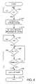
- FIG. 4is a flowchart of the operation of the digital camera shown in FIG. 1A in accordance with an illustrative embodiment of the invention.
- FIG. 5is a flowchart of the operation of the digital camera shown in FIG. 1A in accordance with another illustrative embodiment of the, invention.
- Image blur in a digital cameramay therefore be reduced by delaying capture of a digital image, after actuation of the shutter release button, until the motion of the digital camera satisfies a motion criterion. For example, image capture may be delayed until camera motion reaches one of those instants of minimal motion (a local minimum).
- the delaymay be constrained not to exceed a predetermined timeout period, or other criteria may be used to capture a digital image despite the motion criterion not being satisfied.
- Implementation of this techniquerequires some method for measuring the motion of the digital camera in approximately real time.
- Motion estimation algorithmsmay be relatively simple or quite complex.
- One example of sophisticated motion estimation well known in the video encoding artis that implemented in connection with the Moving Pictures Expert Group (MPEG) video compression standards.
- MPEGMoving Pictures Expert Group
- FIG. 1Ais a block diagram of a digital camera 100 in accordance with an illustrative embodiment of the invention.
- controller 105communicates over data bus 110 with imaging module 115 , input control 120 , display 125 , motion management logic 130 , timer 135 , and memory 140 .
- Memory 140further comprises random-access memory (RAM) 145 and non-volatile memory 150 .
- Optical system 155produces optical images that are converted to digital images by imaging module 115 .
- Optical system 155may comprise, for example, a zoom lens.
- Imaging module 115may comprise an array of photosensors based on charge-coupled-device (CCD) or CMOS technology, an analog-to-digital converter (A/D), a gain control, and a digital signal processor (DSP) (not shown in FIG. 1A ).
- Imaging module 115may be operated in a video preview mode in which digital preview frames are acquired at a rate of, for example, 30 frames per second and shown on display 125 .
- Digital camera 100may operate in this video preview mode while operations such as autofocus, autoexposure, and motion tracking are performed.
- a CMOS photosensor arrayhas the advantage that pixels can be addressed directly like RAM, which simplifies and speeds the readout of the image data for these operations.
- Motion management logic 130may comprise hardware, firmware, software, or a combination thereof. Motion management logic 130 may be conceptualized as having two aspects: motion measurement logic 132 and control logic 134 , as shown in FIG. 1B . Motion measurement logic 132 performs motion estimation on digital preview frames obtained from imaging module 115 during video preview mode. These digital preview frames may be of a lower resolution than a final digital image to facilitate video preview mode. Control logic 134 analyzes motion estimation information obtained from motion measurement logic 132 to determine when a digital image should be captured after capture of an image has been requested. In one illustrative embodiment, controller 105 comprises a microprocessor, and motion management logic 130 comprises stored program instructions in software or firmware or a combination thereof that may be executed by controller 105 .
- controller 105may be termed, functionally, a motion tracking subsystem that outputs an indication of the motion of digital camera 100 as a function of time.
- Controller 105in accordance with control logic 134 , selects the instant of image capture based on the output of the motion tracking subsystem.
- FIG. 1Cis a circuit diagram of input control 120 in accordance with an illustrative embodiment of the invention.
- shutter release button 160is capable of actuating, sequentially, switches S 1 165 and S 2 170 .
- switch S 1 165is closed.
- switch S 2 170is also closed.
- signals 175 and 180Prior to the closing of switches S 1 165 and S 2 170 , signals 175 and 180 , respectively, are both in a logic “high” state.
- Signals 175 and 180are connected with data bus 110 .
- the logic “high” stateis provided by connection of the switches between a common ground and a positive voltage +V across pull-up resistors 185 and 190 .
- switch S 1 165When switch S 1 165 is closed, the corresponding signal 175 is pulled down to ground potential, generating a logic “low. ” Likewise, when switch S 2 170 is closed, the corresponding signal 180 is pulled down to ground potential, generating a logic “low.”
- Input control 120may be used to trigger multiple operations in digital camera 100 .
- actuation of switch S 1 165may activate autofocus and autoexposure.
- a motion-tracking modemay be activated in which the motion of digital camera 100 is tracked.
- Actuation of S 2 170may signal a request that a digital image be captured and stored. In a prior-art digital camera, such capture would be immediate (without intentional delay). To minimize image blur caused by camera motion, however, it is advantageous to delay capture of the digital image until a moment when the motion of digital camera 100 is at an approximate local minimum.
- input control 120may include only one switch instead of two.
- a single signal from input control 120may request the capture of a digital image, and motion tracking may be activated by a separate input signal (e.g., the power of digital camera 100 being turned on) or by the same single signal from input control 120 .
- Motion estimationgenerally involves comparing at least one picture element (pixel) in a first frame with at least one pixel in a second frame to discern a change in the scene during the interval between the two frames. This process may be repeated for successive pairs of frames to track camera motion relative to the background of the scene in approximately real time. In the context of the instant invention, motion estimation may be performed on digital preview frames obtained in the video preview mode of digital camera 100 .
- the comparison of pixelsmay also be implemented in a variety of ways. For example, the magnitude of the pixel-by-pixel difference in brightness (luminance) may be computed. Alternatively, a pixel-by-pixel correlation (multiplication) may be performed. If the pixels compared are in corresponding locations in the two digital preview frames, an indication may be obtained that motion of some sort between the frames occurred but not how much or in what direction. For this reason, motion estimation techniques typically also include a search algorithm in which one or more groups of pixels in a first digital preview frame are compared with groups of pixels within a predetermined search region surrounding each corresponding location in a second digital preview frame. A motion estimation algorithm typically computes a motion vector indicating the magnitude and direction of motion during a particular interval. This motion vector may be expressed conveniently as horizontal and vertical motion components.
- FIG. 2Adepicts a digital preview frame 205 in accordance with an illustrative embodiment of the invention.
- Motion estimationmay be performed using one or more pixels within motion measurement region 210 (cross-hatched in FIG. 2A ).
- motion measurement region 210comprises a central portion of digital preview frame 205 .
- Such a regionmay coincide with the region used in performing autofocus or autoexposure.
- motion estimationmay share virtually the same video preview mode of digital camera 100 with autofocus and autoexposure.
- One disadvantage of this approachis that a moving subject within the central portion of digital preview frame 205 may be detected instead of the motion of digital camera 100 relative to the background.
- FIG. 2Bshows one method for overcoming the problem of subject motion in accordance with an illustrative embodiment of the invention.
- motion measurement region 210comprises a peripheral portion of digital preview frame 205 where an important subject is less likely to be found. By confining motion estimation to the periphery, subject motion may be excluded, allowing the motion of digital camera 100 relative to the background of the scene to be measured.
- a window function applied at the boundary 215 delineating motion measurement region 210may be advantageous for the same reason.
- FIG. 3Ais an illustration of a movement trajectory of a digital camera in accordance with an illustrative embodiment of the invention.
- Trajectory 305 in FIG. 3 Adepicts the path of movement made by digital camera 100 during an arbitrary period prior to an image being captured.
- Local minima 310where the motion of digital camera 100 changes direction, are circled. Capturing a digital image at one of these local minima 310 may reduce image blur. Since the motion of digital camera 100 may not reach a local minimum in the horizontal direction at the same instance it reaches a local minimum in the vertical direction, this must be taken into account in designing criteria for image capture.
- motion measurement logic 132measures horizontal and vertical motion components (e.g., velocities), one possible choice is the square root of the sum of the horizontal motion component squared and the vertical motion component squared (magnitude of the motion vector). Another possible choice is the sum of the absolute value of the horizontal motion component and the absolute value of the vertical motion component.
- FIG. 3Bis an illustrative plot 315 of the magnitude of composite motion of digital camera 100 annotated with time and threshold parameters in accordance with an illustrative embodiment of the invention.
- threshold 320serves as a motion criterion for selecting the instant of image capture at an approximate local minimum.
- a digital imageis captured when the magnitude of motion drops below threshold 320 (point 330 in FIG. 3B ) following activation of switch S 2 170 at time 325 . If the magnitude of motion does not drop below threshold 320 within a predetermined timeout period 335 , the digital image may be captured at time 340 .
- the choice of timeout period 335may vary with application or situation, but it would likely not exceed 0.1 second.
- the imagemay be captured, despite threshold 320 not being satisfied, if the motion of digital camera 100 is found to be decreasing (in terms of velocity, digital camera 100 is decelerating).
- An example of such an interval of decreasing motionis that from point 345 to point 350 . Anticipating an approximate minimum in this way is particularly useful in accounting for readout and computational lags in the motion estimation process.
- Threshold 320may be selected based on any of a variety of factors or a combination thereof. In one embodiment, threshold 320 is selected based on the minimum and maximum motion measured (e.g., minimum and maximum velocities) during an interval 355 between actuation of switch S 1 165 and actuation of switch S 2 170 (see FIG. 3B ). Such minimum and maximum motion measurements within interval 355 are illustrated by points 360 and 365 , respectively. Threshold 320 may be chosen, for example, as a particular fraction of maximum 365 or as a value lying between minimum 360 and maximum 365 . In a different embodiment, threshold 320 may be chosen based on the current focal length setting of optical system 155 .
- minimum and maximum motion measurede.g., minimum and maximum velocities
- threshold 320may need to be smaller for a telephoto focal length than for a wide-angle focal length.
- a faster shutter speedalso renders motion of digital camera 100 less critical. Consequently, threshold 320 may be larger (less strict) if digital camera 100 is operating at a fast shutter speed (e.g., 1/500 of a second) than if digital camera is operating at a slower shutter speed (e.g., 1/30 of a second).
- Another factor that may be used in selecting threshold 320is interval 355 in FIG. 3B .
- threshold 320may be chosen differently depending on whether interval 355 is short or long.
- the thresholdcan be set based on prior characterization of the typical amount of camera motion after actuation of S 1 165 . For example, if a high degree of motion is detected, due to an unsteady user, one-handed operation, etc., a higher threshold may be selected.
- threshold 320may be altered after actuation of switch S 2 170 .
- threshold 320may be increased (making the motion criterion less strict) with the passage of time after the actuation of S 2 .
- Thisis yet another alternative to timeout period 335 and capturing the digital image upon detected deceleration of digital camera 100 .
- FIG. 4is a flowchart of the operation of digital camera 100 in accordance with an illustrative embodiment of the invention. If switch S 1 165 is actuated at 405 , autofocus and autoexposure are performed at 410 . Once autofocus and autoexposure are complete, digital camera 100 enters a motion measurement mode at 415 in which the motion tracking subsystem measures the motion of digital camera 100 as a function of time, as explained above. If switch S 2 170 is actuated at 420 , control proceeds to 425 , and timer 135 may be reset to count timeout period 335 . At 425 , the output of motion measurement logic 132 is compared with threshold 320 .
- a digital imagemay be captured immediately at 435 . Otherwise, control proceeds to 430 .
- controller 105checks timer 135 to determine whether timeout period 335 has expired. If so, the digital image may be captured at 435 . Otherwise, control returns to 425 . Once the digital image has been captured, the process terminates at 440 .
- FIG. 5is a flowchart of the operation of digital camera 100 in accordance with another illustrative embodiment of the invention.
- the process in FIG. 5is similar to that in FIG. 4 , except that a decrease (deceleration, in terms of velocity) in the motion of digital camera 100 is the criterion for capturing a digital image at 445 , when threshold 320 is not satisfied at 425 .
Landscapes
- Engineering & Computer Science (AREA)
- Multimedia (AREA)
- Signal Processing (AREA)
- Studio Devices (AREA)
- Adjustment Of Camera Lenses (AREA)
Abstract
Description
Claims (16)
Priority Applications (5)
| Application Number | Priority Date | Filing Date | Title |
|---|---|---|---|
| US10/339,132US7212230B2 (en) | 2003-01-08 | 2003-01-08 | Digital camera having a motion tracking subsystem responsive to input control for tracking motion of the digital camera |
| TW092120224ATW200412786A (en) | 2003-01-08 | 2003-07-24 | Apparatus and method for reducing image blur in a digital camera |
| DE10344058ADE10344058B4 (en) | 2003-01-08 | 2003-09-23 | Apparatus and method for reducing image blur in a digital camera |
| JP2004001765AJP4098251B2 (en) | 2003-01-08 | 2004-01-07 | Apparatus and method for reducing image blur in a digital camera |
| US11/786,210US7787015B2 (en) | 2003-01-08 | 2007-04-10 | Apparatus and method for reducing image blur in a digital camera |
Applications Claiming Priority (1)
| Application Number | Priority Date | Filing Date | Title |
|---|---|---|---|
| US10/339,132US7212230B2 (en) | 2003-01-08 | 2003-01-08 | Digital camera having a motion tracking subsystem responsive to input control for tracking motion of the digital camera |
Related Child Applications (1)
| Application Number | Title | Priority Date | Filing Date |
|---|---|---|---|
| US11/786,210DivisionUS7787015B2 (en) | 2003-01-08 | 2007-04-10 | Apparatus and method for reducing image blur in a digital camera |
Publications (2)
| Publication Number | Publication Date |
|---|---|
| US20040130628A1 US20040130628A1 (en) | 2004-07-08 |
| US7212230B2true US7212230B2 (en) | 2007-05-01 |
Family
ID=32655447
Family Applications (2)
| Application Number | Title | Priority Date | Filing Date |
|---|---|---|---|
| US10/339,132Expired - Fee RelatedUS7212230B2 (en) | 2003-01-08 | 2003-01-08 | Digital camera having a motion tracking subsystem responsive to input control for tracking motion of the digital camera |
| US11/786,210Expired - Fee RelatedUS7787015B2 (en) | 2003-01-08 | 2007-04-10 | Apparatus and method for reducing image blur in a digital camera |
Family Applications After (1)
| Application Number | Title | Priority Date | Filing Date |
|---|---|---|---|
| US11/786,210Expired - Fee RelatedUS7787015B2 (en) | 2003-01-08 | 2007-04-10 | Apparatus and method for reducing image blur in a digital camera |
Country Status (4)
| Country | Link |
|---|---|
| US (2) | US7212230B2 (en) |
| JP (1) | JP4098251B2 (en) |
| DE (1) | DE10344058B4 (en) |
| TW (1) | TW200412786A (en) |
Cited By (23)
| Publication number | Priority date | Publication date | Assignee | Title |
|---|---|---|---|---|
| US20040263633A1 (en)* | 2002-08-08 | 2004-12-30 | Junichi Shinohara | Imaging apparatus |
| US20060228049A1 (en)* | 2005-02-17 | 2006-10-12 | Stmicroelectronics S.A. | Method for capturing images comprising a measurement of local motions |
| US20060293558A1 (en)* | 2005-06-17 | 2006-12-28 | De Groen Piet C | Colonoscopy video processing for quality metrics determination |
| US20080101782A1 (en)* | 2006-10-27 | 2008-05-01 | Yu-Cheng Huang | Camera and image stabilization thereof |
| US20080291597A1 (en)* | 2007-05-22 | 2008-11-27 | Seibel Eric J | Scanning beam device having different image acquisition modes |
| US20090027544A1 (en)* | 2007-07-25 | 2009-01-29 | Micron Technology, Inc. | Solid state optical motion compensation |
| US20090174782A1 (en)* | 2008-01-07 | 2009-07-09 | Philippe Kahn | Method and Apparatus for Improving Photo Image Quality |
| US20100149350A1 (en)* | 2008-12-12 | 2010-06-17 | Sanyo Electric Co., Ltd. | Image Sensing Apparatus And Image Sensing Method |
| US7982770B1 (en) | 2006-09-08 | 2011-07-19 | Dp Technologies, Inc. | Method and apparatus to provide improved image quality in a camera |
| US8064759B1 (en) | 2009-04-15 | 2011-11-22 | Dp Technologies, Inc. | Method and apparatus for motion-state based image acquisition |
| US8141473B2 (en) | 2009-03-18 | 2012-03-27 | Alliant Techsystems Inc. | Apparatus for synthetic weapon stabilization and firing |
| US8285344B2 (en) | 2008-05-21 | 2012-10-09 | DP Technlogies, Inc. | Method and apparatus for adjusting audio for a user environment |
| US8555282B1 (en) | 2007-07-27 | 2013-10-08 | Dp Technologies, Inc. | Optimizing preemptive operating system with motion sensing |
| US8620353B1 (en) | 2007-01-26 | 2013-12-31 | Dp Technologies, Inc. | Automatic sharing and publication of multimedia from a mobile device |
| US8872646B2 (en) | 2008-10-08 | 2014-10-28 | Dp Technologies, Inc. | Method and system for waking up a device due to motion |
| US8902154B1 (en) | 2006-07-11 | 2014-12-02 | Dp Technologies, Inc. | Method and apparatus for utilizing motion user interface |
| US8949070B1 (en) | 2007-02-08 | 2015-02-03 | Dp Technologies, Inc. | Human activity monitoring device with activity identification |
| US8996332B2 (en) | 2008-06-24 | 2015-03-31 | Dp Technologies, Inc. | Program setting adjustments based on activity identification |
| US20160142730A1 (en)* | 2014-11-14 | 2016-05-19 | Sony Corporation | Method and system for processing video content |
| US9390229B1 (en) | 2006-04-26 | 2016-07-12 | Dp Technologies, Inc. | Method and apparatus for a health phone |
| US9529437B2 (en) | 2009-05-26 | 2016-12-27 | Dp Technologies, Inc. | Method and apparatus for a motion state aware device |
| US10845188B2 (en) | 2016-01-05 | 2020-11-24 | Microsoft Technology Licensing, Llc | Motion capture from a mobile self-tracking device |
| US20230138331A1 (en)* | 2019-10-07 | 2023-05-04 | Inspekto A.M.V. Ltd. | Motion in images used in a visual inspection process |
Families Citing this family (78)
| Publication number | Priority date | Publication date | Assignee | Title |
|---|---|---|---|---|
| US20040100563A1 (en)* | 2002-11-27 | 2004-05-27 | Sezai Sablak | Video tracking system and method |
| JP2004357202A (en)* | 2003-05-30 | 2004-12-16 | Canon Inc | Imaging equipment |
| US8264576B2 (en) | 2007-03-05 | 2012-09-11 | DigitalOptics Corporation Europe Limited | RGBW sensor array |
| US8989516B2 (en) | 2007-09-18 | 2015-03-24 | Fotonation Limited | Image processing method and apparatus |
| US7639889B2 (en) | 2004-11-10 | 2009-12-29 | Fotonation Ireland Ltd. | Method of notifying users regarding motion artifacts based on image analysis |
| US8698924B2 (en)* | 2007-03-05 | 2014-04-15 | DigitalOptics Corporation Europe Limited | Tone mapping for low-light video frame enhancement |
| US9160897B2 (en)* | 2007-06-14 | 2015-10-13 | Fotonation Limited | Fast motion estimation method |
| US8199222B2 (en)* | 2007-03-05 | 2012-06-12 | DigitalOptics Corporation Europe Limited | Low-light video frame enhancement |
| US7636486B2 (en)* | 2004-11-10 | 2009-12-22 | Fotonation Ireland Ltd. | Method of determining PSF using multiple instances of a nominally similar scene |
| US8417055B2 (en) | 2007-03-05 | 2013-04-09 | DigitalOptics Corporation Europe Limited | Image processing method and apparatus |
| JP4599920B2 (en)* | 2003-09-02 | 2010-12-15 | セイコーエプソン株式会社 | Image generating apparatus and image generating method |
| US7742077B2 (en)* | 2004-02-19 | 2010-06-22 | Robert Bosch Gmbh | Image stabilization system and method for a video camera |
| US7382400B2 (en)* | 2004-02-19 | 2008-06-03 | Robert Bosch Gmbh | Image stabilization system and method for a video camera |
| US9210312B2 (en)* | 2004-06-02 | 2015-12-08 | Bosch Security Systems, Inc. | Virtual mask for use in autotracking video camera images |
| US20050270372A1 (en)* | 2004-06-02 | 2005-12-08 | Henninger Paul E Iii | On-screen display and privacy masking apparatus and method |
| US8212872B2 (en)* | 2004-06-02 | 2012-07-03 | Robert Bosch Gmbh | Transformable privacy mask for video camera images |
| US20050285948A1 (en)* | 2004-06-22 | 2005-12-29 | Harvey Weinberg | System and method for processing a digital camera image |
| JP5186519B2 (en)* | 2004-07-23 | 2013-04-17 | フクビ化学工業株式会社 | Mounting spacer and mounting structure |
| US7639888B2 (en)* | 2004-11-10 | 2009-12-29 | Fotonation Ireland Ltd. | Method and apparatus for initiating subsequent exposures based on determination of motion blurring artifacts |
| JP4311668B2 (en)* | 2004-11-15 | 2009-08-12 | オリンパス株式会社 | Imaging apparatus, imaging system, and image capturing method |
| WO2006083563A2 (en)* | 2005-02-01 | 2006-08-10 | Analog Devices, Inc. | Camera with acceleration sensor |
| JP2006245815A (en)* | 2005-03-01 | 2006-09-14 | Fuji Photo Film Co Ltd | Imaging apparatus |
| WO2007007225A2 (en)* | 2005-07-12 | 2007-01-18 | Nxp B.V. | Method and device for removing motion blur effects |
| JP2007110622A (en)* | 2005-10-17 | 2007-04-26 | Canon Inc | Imaging apparatus, control method, control program, and storage medium |
| US7546026B2 (en) | 2005-10-25 | 2009-06-09 | Zoran Corporation | Camera exposure optimization techniques that take camera and scene motion into account |
| US20070098383A1 (en)* | 2005-10-28 | 2007-05-03 | Stavely Donald J | Motion blur reduction and compensation |
| US20070097221A1 (en)* | 2005-10-28 | 2007-05-03 | Stavely Donald J | Systems and methods of exposure restart for cameras |
| US20070098382A1 (en)* | 2005-10-28 | 2007-05-03 | Stavely Donald J | Exposure boundary selection for motion blur compensation |
| US20070127903A1 (en)* | 2005-11-29 | 2007-06-07 | Seiko Epson Corporation | Photographic apparatus, method of controlling photographic apparatus, and recording medium |
| US7460773B2 (en)* | 2005-12-05 | 2008-12-02 | Hewlett-Packard Development Company, L.P. | Avoiding image artifacts caused by camera vibration |
| TW200731781A (en)* | 2006-02-03 | 2007-08-16 | Benq Corp | Methods and systems for automatic shuttering |
| US7620304B2 (en)* | 2006-04-24 | 2009-11-17 | Hewlett-Packard Development Company, L.P. | Method and apparatus for reducing shutter lag in a digital imaging device |
| IES20070229A2 (en)* | 2006-06-05 | 2007-10-03 | Fotonation Vision Ltd | Image acquisition method and apparatus |
| US7952612B2 (en)* | 2006-06-22 | 2011-05-31 | Nokia Corporation | Method and system for image construction using multiple exposures |
| US8068140B2 (en)* | 2006-08-07 | 2011-11-29 | Avago Technologies General Ip (Singapore) Pte. Ltd. | Still image stabilization suitable for compact camera environments |
| US20080094496A1 (en)* | 2006-10-24 | 2008-04-24 | Kong Qiao Wang | Mobile communication terminal |
| US7697836B2 (en)* | 2006-10-25 | 2010-04-13 | Zoran Corporation | Control of artificial lighting of a scene to reduce effects of motion in the scene on an image being acquired |
| JP2008141370A (en)* | 2006-11-30 | 2008-06-19 | Funai Electric Co Ltd | Imaging apparatus |
| JP4853320B2 (en)* | 2007-02-15 | 2012-01-11 | ソニー株式会社 | Image processing apparatus and image processing method |
| US9307212B2 (en) | 2007-03-05 | 2016-04-05 | Fotonation Limited | Tone mapping for low-light video frame enhancement |
| JP2008225550A (en)* | 2007-03-08 | 2008-09-25 | Sony Corp | Image processing apparatus, image processing method, and program |
| JP4424364B2 (en)* | 2007-03-19 | 2010-03-03 | ソニー株式会社 | Image processing apparatus and image processing method |
| US20080231714A1 (en)* | 2007-03-22 | 2008-09-25 | Texas Instruments Incorporated | System and method for capturing images |
| US7773118B2 (en)* | 2007-03-25 | 2010-08-10 | Fotonation Vision Limited | Handheld article with movement discrimination |
| JP4396720B2 (en)* | 2007-03-26 | 2010-01-13 | ソニー株式会社 | Image processing apparatus, image processing method, and program |
| TWI344305B (en) | 2007-05-16 | 2011-06-21 | Alpha Imaging Technology Corp | Image processing method and apparatus thereof |
| JP2009003334A (en)* | 2007-06-25 | 2009-01-08 | Sony Corp | Image pick-up device, and imaging control method |
| US9179060B2 (en)* | 2007-09-27 | 2015-11-03 | Qualcomm Incorporated | Method and apparatus for camera shake effect image stabilization |
| US10127422B1 (en)* | 2007-12-21 | 2018-11-13 | Cognex Corporation | Handheld code reader having a motion sensor |
| US8482620B2 (en) | 2008-03-11 | 2013-07-09 | Csr Technology Inc. | Image enhancement based on multiple frames and motion estimation |
| KR101538654B1 (en)* | 2008-07-07 | 2015-07-22 | 삼성전자주식회사 | Digital photographing apparatus for controlling hand shake correction operation and control method therefor |
| KR101499133B1 (en)* | 2008-10-28 | 2015-03-11 | 삼성전자주식회사 | Method and device for performing menu in wireless terminal |
| KR101618759B1 (en)* | 2008-12-24 | 2016-05-09 | 삼성전자주식회사 | Apparatus and method for capturing image |
| KR101567812B1 (en)* | 2008-12-31 | 2015-11-11 | 삼성전자주식회사 | Digital camera supporting intelligent self-timer mode and its control method |
| KR101532610B1 (en)* | 2009-01-22 | 2015-06-30 | 삼성전자주식회사 | A digital photographing device, a method for controlling a digital photographing device, a computer-readable storage medium |
| US20100277603A1 (en)* | 2009-04-29 | 2010-11-04 | Apple Inc. | Image Capture Device to Minimize the Effect of Device Movement |
| US8786761B2 (en) | 2009-06-05 | 2014-07-22 | Apple Inc. | Continuous autofocus mechanisms for image capturing devices |
| US20110109752A1 (en)* | 2009-11-11 | 2011-05-12 | Omnivision Technologies, Inc. | Image sensor with shaking compensation |
| CN102103301B (en)* | 2009-12-17 | 2014-03-05 | 深圳富泰宏精密工业有限公司 | Device and method for taking picture |
| US8224176B1 (en) | 2011-01-10 | 2012-07-17 | Eastman Kodak Company | Combined ambient and flash exposure for improved image quality |
| US8922707B2 (en)* | 2011-01-26 | 2014-12-30 | Aptina Imaging Corporation | Systems and methods for luminance-based scene-change detection for continuous autofocus |
| US8379934B2 (en) | 2011-02-04 | 2013-02-19 | Eastman Kodak Company | Estimating subject motion between image frames |
| US8428308B2 (en) | 2011-02-04 | 2013-04-23 | Apple Inc. | Estimating subject motion for capture setting determination |
| US8665338B2 (en) | 2011-03-03 | 2014-03-04 | Qualcomm Incorporated | Blurred image detection for text recognition |
| US8736704B2 (en) | 2011-03-25 | 2014-05-27 | Apple Inc. | Digital camera for capturing an image sequence |
| US8736697B2 (en) | 2011-03-25 | 2014-05-27 | Apple Inc. | Digital camera having burst image capture mode |
| US8736716B2 (en) | 2011-04-06 | 2014-05-27 | Apple Inc. | Digital camera having variable duration burst mode |
| US9609217B2 (en)* | 2011-11-02 | 2017-03-28 | Mediatek Inc. | Image-based motion sensor and related multi-purpose camera system |
| KR20130056747A (en)* | 2011-11-22 | 2013-05-30 | 삼성전자주식회사 | Method for photographing image and image photographing device thereof |
| US8542975B2 (en) | 2011-12-22 | 2013-09-24 | Blackberry Limited | Method to stabilize video stream using on-device positional sensors |
| US20140247368A1 (en)* | 2013-03-04 | 2014-09-04 | Colby Labs, Llc | Ready click camera control |
| CN104281996B (en)* | 2013-07-09 | 2017-05-24 | 聚晶半导体股份有限公司 | Image denoising method and image denoising device |
| EP3005678B1 (en)* | 2014-02-18 | 2020-12-23 | Huawei Technologies Co., Ltd. | Method for obtaining a picture and multi-camera system |
| EP3998571A1 (en)* | 2014-12-23 | 2022-05-18 | Bit Body Inc. | Methods of capturing images and making garments |
| US10170157B2 (en)* | 2015-06-07 | 2019-01-01 | Apple Inc. | Method and apparatus for finding and using video portions that are relevant to adjacent still images |
| WO2019028359A1 (en) | 2017-08-04 | 2019-02-07 | SMPL Inc. | System and method for sensor-driven automatic device interaction |
| JP7286294B2 (en)* | 2017-10-27 | 2023-06-05 | キヤノン株式会社 | IMAGING DEVICE, IMAGING DEVICE CONTROL METHOD, AND PROGRAM |
| KR102543529B1 (en) | 2018-08-14 | 2023-06-15 | 현대모비스 주식회사 | Apparatus for processing image blurring and method thereof |
Citations (7)
| Publication number | Priority date | Publication date | Assignee | Title |
|---|---|---|---|---|
| US5307113A (en) | 1986-11-20 | 1994-04-26 | Canon Kabushiki Kaisha | Imaging apparatus with means for detecting and preventing hand shake |
| US5402197A (en)* | 1992-09-04 | 1995-03-28 | Nikon Corporation | Camera shake alarming apparatus |
| US5708063A (en)* | 1993-05-11 | 1998-01-13 | Tokuyama Corporation | Photochromic compound |
| US5790490A (en)* | 1996-05-10 | 1998-08-04 | Olympus Optical Co., Ltd. | Anti-shake camera |
| US6480629B1 (en) | 1999-04-06 | 2002-11-12 | Koninklijke Philips Electronics N.V. | Motion estimation method using orthogonal-sum block matching |
| US6487369B1 (en)* | 1999-04-26 | 2002-11-26 | Olympus Optical Co., Ltd. | Camera with blur reducing function |
| US20030151672A1 (en)* | 2002-02-11 | 2003-08-14 | Robins Mark N. | Motion detection in an image capturing device |
Family Cites Families (8)
| Publication number | Priority date | Publication date | Assignee | Title |
|---|---|---|---|---|
| DE68929448T2 (en)* | 1988-09-09 | 2003-10-02 | Canon K.K., Tokio/Tokyo | Automatic image stabilization device |
| US5150150A (en)* | 1989-09-06 | 1992-09-22 | Asahi Kogaku Kogyo Kabushiki Kaisha | Apparatus for preventing image from being blurred in camera |
| US5103254A (en)* | 1990-05-29 | 1992-04-07 | Eastman Kodak Company | Camera with subject highlighting and motion detection |
| US5365280A (en)* | 1992-06-26 | 1994-11-15 | U.S. Philips Corporation | Method and apparatus for discriminating between movie film and non-movie film and generating a picture signal processing mode control signal |
| KR0175372B1 (en)* | 1995-08-29 | 1999-03-20 | 김광호 | Method & apparatus for detecting movement vector |
| KR100252080B1 (en)* | 1997-10-10 | 2000-04-15 | 윤종용 | Image Stabilization Device and Image Stabilization Method Using Motion Correction of Input Image Using Bit Plane Matching |
| US6747690B2 (en)* | 2000-07-11 | 2004-06-08 | Phase One A/S | Digital camera with integrated accelerometers |
| US6549729B1 (en) | 2001-11-28 | 2003-04-15 | Hewlett Packard Development Company, L.P. | Camera that operates in accordance with the speed requirements of the photographer |
- 2003
- 2003-01-08USUS10/339,132patent/US7212230B2/ennot_activeExpired - Fee Related
- 2003-07-24TWTW092120224Apatent/TW200412786A/enunknown
- 2003-09-23DEDE10344058Apatent/DE10344058B4/ennot_activeExpired - Fee Related
- 2004
- 2004-01-07JPJP2004001765Apatent/JP4098251B2/ennot_activeExpired - Fee Related
- 2007
- 2007-04-10USUS11/786,210patent/US7787015B2/ennot_activeExpired - Fee Related
Patent Citations (7)
| Publication number | Priority date | Publication date | Assignee | Title |
|---|---|---|---|---|
| US5307113A (en) | 1986-11-20 | 1994-04-26 | Canon Kabushiki Kaisha | Imaging apparatus with means for detecting and preventing hand shake |
| US5402197A (en)* | 1992-09-04 | 1995-03-28 | Nikon Corporation | Camera shake alarming apparatus |
| US5708063A (en)* | 1993-05-11 | 1998-01-13 | Tokuyama Corporation | Photochromic compound |
| US5790490A (en)* | 1996-05-10 | 1998-08-04 | Olympus Optical Co., Ltd. | Anti-shake camera |
| US6480629B1 (en) | 1999-04-06 | 2002-11-12 | Koninklijke Philips Electronics N.V. | Motion estimation method using orthogonal-sum block matching |
| US6487369B1 (en)* | 1999-04-26 | 2002-11-26 | Olympus Optical Co., Ltd. | Camera with blur reducing function |
| US20030151672A1 (en)* | 2002-02-11 | 2003-08-14 | Robins Mark N. | Motion detection in an image capturing device |
Non-Patent Citations (1)
| Title |
|---|
| Pending U.S. Appl. No. 09/997,675, filed Nov 28, 2001, "Camera That Operates In Accordance Wtih The Speed Requirements Of The Photographer," Mark N. Robins et al. 10015526-1. |
Cited By (45)
| Publication number | Priority date | Publication date | Assignee | Title |
|---|---|---|---|---|
| US7777802B2 (en) | 2002-08-08 | 2010-08-17 | Ricoh Company, Ltd. | Imaging apparatus including an auto focusing function |
| US7301579B2 (en)* | 2002-08-08 | 2007-11-27 | Ricoh Company, Ltd. | Imaging apparatus |
| US20080036901A1 (en)* | 2002-08-08 | 2008-02-14 | Junichi Shinohara | Imaging apparatus |
| US20040263633A1 (en)* | 2002-08-08 | 2004-12-30 | Junichi Shinohara | Imaging apparatus |
| US20060228049A1 (en)* | 2005-02-17 | 2006-10-12 | Stmicroelectronics S.A. | Method for capturing images comprising a measurement of local motions |
| US8139823B2 (en) | 2005-02-17 | 2012-03-20 | Stmicroelectronics S.A. | Method for capturing images comprising a measurement of local motions |
| US7925051B2 (en)* | 2005-02-17 | 2011-04-12 | Stmicroelectronics Sa | Method for capturing images comprising a measurement of local motions |
| US20060293558A1 (en)* | 2005-06-17 | 2006-12-28 | De Groen Piet C | Colonoscopy video processing for quality metrics determination |
| US7894648B2 (en)* | 2005-06-17 | 2011-02-22 | Mayo Foundation For Medical Education And Research | Colonoscopy video processing for quality metrics determination |
| US9390229B1 (en) | 2006-04-26 | 2016-07-12 | Dp Technologies, Inc. | Method and apparatus for a health phone |
| US9495015B1 (en) | 2006-07-11 | 2016-11-15 | Dp Technologies, Inc. | Method and apparatus for utilizing motion user interface to determine command availability |
| US8902154B1 (en) | 2006-07-11 | 2014-12-02 | Dp Technologies, Inc. | Method and apparatus for utilizing motion user interface |
| US7982770B1 (en) | 2006-09-08 | 2011-07-19 | Dp Technologies, Inc. | Method and apparatus to provide improved image quality in a camera |
| US7822329B2 (en)* | 2006-10-27 | 2010-10-26 | Altek Corporation | Camera and image stabilization thereof |
| US20080101782A1 (en)* | 2006-10-27 | 2008-05-01 | Yu-Cheng Huang | Camera and image stabilization thereof |
| US8620353B1 (en) | 2007-01-26 | 2013-12-31 | Dp Technologies, Inc. | Automatic sharing and publication of multimedia from a mobile device |
| US10744390B1 (en) | 2007-02-08 | 2020-08-18 | Dp Technologies, Inc. | Human activity monitoring device with activity identification |
| US8949070B1 (en) | 2007-02-08 | 2015-02-03 | Dp Technologies, Inc. | Human activity monitoring device with activity identification |
| US20080291597A1 (en)* | 2007-05-22 | 2008-11-27 | Seibel Eric J | Scanning beam device having different image acquisition modes |
| US8212884B2 (en)* | 2007-05-22 | 2012-07-03 | University Of Washington | Scanning beam device having different image acquisition modes |
| US20090027544A1 (en)* | 2007-07-25 | 2009-01-29 | Micron Technology, Inc. | Solid state optical motion compensation |
| US8555282B1 (en) | 2007-07-27 | 2013-10-08 | Dp Technologies, Inc. | Optimizing preemptive operating system with motion sensing |
| US9183044B2 (en) | 2007-07-27 | 2015-11-10 | Dp Technologies, Inc. | Optimizing preemptive operating system with motion sensing |
| US9940161B1 (en) | 2007-07-27 | 2018-04-10 | Dp Technologies, Inc. | Optimizing preemptive operating system with motion sensing |
| US10754683B1 (en) | 2007-07-27 | 2020-08-25 | Dp Technologies, Inc. | Optimizing preemptive operating system with motion sensing |
| US20090174782A1 (en)* | 2008-01-07 | 2009-07-09 | Philippe Kahn | Method and Apparatus for Improving Photo Image Quality |
| US8040382B2 (en)* | 2008-01-07 | 2011-10-18 | Dp Technologies, Inc. | Method and apparatus for improving photo image quality |
| US8285344B2 (en) | 2008-05-21 | 2012-10-09 | DP Technlogies, Inc. | Method and apparatus for adjusting audio for a user environment |
| US8996332B2 (en) | 2008-06-24 | 2015-03-31 | Dp Technologies, Inc. | Program setting adjustments based on activity identification |
| US9797920B2 (en) | 2008-06-24 | 2017-10-24 | DPTechnologies, Inc. | Program setting adjustments based on activity identification |
| US11249104B2 (en) | 2008-06-24 | 2022-02-15 | Huawei Technologies Co., Ltd. | Program setting adjustments based on activity identification |
| US12196775B2 (en) | 2008-06-24 | 2025-01-14 | Huawei Technologies Co., Ltd. | Program setting adjustment based on motion data |
| US12306206B2 (en) | 2008-06-24 | 2025-05-20 | Huawei Technologies Co., Ltd. | Program setting adjustments based on activity identification |
| US12385943B2 (en) | 2008-06-24 | 2025-08-12 | Huawei Technologies Co., Ltd. | Program setting adjustments based on activity identification |
| US8872646B2 (en) | 2008-10-08 | 2014-10-28 | Dp Technologies, Inc. | Method and system for waking up a device due to motion |
| US20100149350A1 (en)* | 2008-12-12 | 2010-06-17 | Sanyo Electric Co., Ltd. | Image Sensing Apparatus And Image Sensing Method |
| US8223223B2 (en)* | 2008-12-12 | 2012-07-17 | Sanyo Electric Co., Ltd. | Image sensing apparatus and image sensing method |
| US8141473B2 (en) | 2009-03-18 | 2012-03-27 | Alliant Techsystems Inc. | Apparatus for synthetic weapon stabilization and firing |
| US8555771B2 (en) | 2009-03-18 | 2013-10-15 | Alliant Techsystems Inc. | Apparatus for synthetic weapon stabilization and firing |
| US8064759B1 (en) | 2009-04-15 | 2011-11-22 | Dp Technologies, Inc. | Method and apparatus for motion-state based image acquisition |
| US9529437B2 (en) | 2009-05-26 | 2016-12-27 | Dp Technologies, Inc. | Method and apparatus for a motion state aware device |
| US9544615B2 (en)* | 2014-11-14 | 2017-01-10 | Sony Corporation | Method and system for processing video content |
| US20160142730A1 (en)* | 2014-11-14 | 2016-05-19 | Sony Corporation | Method and system for processing video content |
| US10845188B2 (en) | 2016-01-05 | 2020-11-24 | Microsoft Technology Licensing, Llc | Motion capture from a mobile self-tracking device |
| US20230138331A1 (en)* | 2019-10-07 | 2023-05-04 | Inspekto A.M.V. Ltd. | Motion in images used in a visual inspection process |
Also Published As
| Publication number | Publication date |
|---|---|
| JP4098251B2 (en) | 2008-06-11 |
| TW200412786A (en) | 2004-07-16 |
| US7787015B2 (en) | 2010-08-31 |
| DE10344058B4 (en) | 2011-02-10 |
| JP2004215283A (en) | 2004-07-29 |
| DE10344058A1 (en) | 2004-07-29 |
| US20070188617A1 (en) | 2007-08-16 |
| US20040130628A1 (en) | 2004-07-08 |
Similar Documents
| Publication | Publication Date | Title |
|---|---|---|
| US7212230B2 (en) | Digital camera having a motion tracking subsystem responsive to input control for tracking motion of the digital camera | |
| US10356321B2 (en) | Imaging apparatus with focus adjustment control and exposure adjustment control | |
| US7747159B2 (en) | Focusing device and image-capturing device provided with the same | |
| US8675119B2 (en) | Adaptive imaging using digital light processing | |
| JP4018695B2 (en) | Method and apparatus for continuous focusing and exposure adjustment in a digital imaging device | |
| EP2081374B1 (en) | Imaging apparatus and its control method | |
| CN108156362B (en) | Anti-shake method of camera and camera | |
| US8994783B2 (en) | Image pickup apparatus that automatically determines shooting mode most suitable for shooting scene, control method therefor, and storage medium | |
| JPH09200597A (en) | Automatic focusing detector | |
| US10855915B2 (en) | Image pickup apparatus capable of consecutively displaying different types of image, control method, and storage medium | |
| JP2011135152A (en) | Image pickup apparatus and method of picking up image | |
| US11190704B2 (en) | Imaging apparatus and control method for performing live view display of a tracked object | |
| EP0956695B1 (en) | Scene-motion based dynamic shutter speed adjustment system and method | |
| US8836821B2 (en) | Electronic camera | |
| US7193650B2 (en) | Image sensing apparatus | |
| KR20100079832A (en) | Digital camera supporting an intelligent self-timer mode and controlling method for the same | |
| US8398317B2 (en) | Method of controlling imaging apparatus and imaging apparatus using the same | |
| JP2003143486A (en) | Image pickup device | |
| US10972664B2 (en) | Image blurring correction apparatus, imaging apparatus, and image blurring correction method that corrects image blurring based on panning detection and angular velocity | |
| JP2754808B2 (en) | Video camera with image stabilization function | |
| JP2002238000A (en) | Imaging device and imaging method | |
| US20250294250A1 (en) | Exposure control device, operation method for exposure control device, operation program for exposure control device, focus control device, and imaging apparatus | |
| US20240196089A1 (en) | Detecting apparatus, image pickup apparatus, and detecting method | |
| JPH08294041A (en) | Imaging device | |
| JP2003333438A (en) | Image motion compensation device |
Legal Events
| Date | Code | Title | Description |
|---|---|---|---|
| AS | Assignment | Owner name:HEWLETT-PACKARD COMPANY, COLORADO Free format text:ASSIGNMENT OF ASSIGNORS INTEREST;ASSIGNOR:STAVELY, DONALD J.;REEL/FRAME:013736/0133 Effective date:20030106 | |
| AS | Assignment | Owner name:HEWLETT-PACKARD DEVELOPMENT COMPANY, L.P., COLORADO Free format text:ASSIGNMENT OF ASSIGNORS INTEREST;ASSIGNOR:HEWLETT-PACKARD COMPANY;REEL/FRAME:013776/0928 Effective date:20030131 Owner name:HEWLETT-PACKARD DEVELOPMENT COMPANY, L.P., COLORAD Free format text:ASSIGNMENT OF ASSIGNORS INTEREST;ASSIGNOR:HEWLETT-PACKARD COMPANY;REEL/FRAME:013776/0928 Effective date:20030131 Owner name:HEWLETT-PACKARD DEVELOPMENT COMPANY, L.P.,COLORADO Free format text:ASSIGNMENT OF ASSIGNORS INTEREST;ASSIGNOR:HEWLETT-PACKARD COMPANY;REEL/FRAME:013776/0928 Effective date:20030131 | |
| STCF | Information on status: patent grant | Free format text:PATENTED CASE | |
| CC | Certificate of correction | ||
| FPAY | Fee payment | Year of fee payment:4 | |
| FPAY | Fee payment | Year of fee payment:8 | |
| FEPP | Fee payment procedure | Free format text:MAINTENANCE FEE REMINDER MAILED (ORIGINAL EVENT CODE: REM.); ENTITY STATUS OF PATENT OWNER: LARGE ENTITY | |
| LAPS | Lapse for failure to pay maintenance fees | Free format text:PATENT EXPIRED FOR FAILURE TO PAY MAINTENANCE FEES (ORIGINAL EVENT CODE: EXP.); ENTITY STATUS OF PATENT OWNER: LARGE ENTITY | |
| STCH | Information on status: patent discontinuation | Free format text:PATENT EXPIRED DUE TO NONPAYMENT OF MAINTENANCE FEES UNDER 37 CFR 1.362 | |
| FP | Lapsed due to failure to pay maintenance fee | Effective date:20190501 |