US7210817B2 - Method, system and device for delivering phototherapy to a patient - Google Patents
Method, system and device for delivering phototherapy to a patientDownload PDFInfo
- Publication number
- US7210817B2 US7210817B2US10/833,905US83390504AUS7210817B2US 7210817 B2US7210817 B2US 7210817B2US 83390504 AUS83390504 AUS 83390504AUS 7210817 B2US7210817 B2US 7210817B2
- Authority
- US
- United States
- Prior art keywords
- substrate
- flexible
- mat
- facing surface
- light
- Prior art date
- Legal status (The legal status is an assumption and is not a legal conclusion. Google has not performed a legal analysis and makes no representation as to the accuracy of the status listed.)
- Expired - Lifetime, expires
Links
Images


Classifications
- F—MECHANICAL ENGINEERING; LIGHTING; HEATING; WEAPONS; BLASTING
- F21—LIGHTING
- F21K—NON-ELECTRIC LIGHT SOURCES USING LUMINESCENCE; LIGHT SOURCES USING ELECTROCHEMILUMINESCENCE; LIGHT SOURCES USING CHARGES OF COMBUSTIBLE MATERIAL; LIGHT SOURCES USING SEMICONDUCTOR DEVICES AS LIGHT-GENERATING ELEMENTS; LIGHT SOURCES NOT OTHERWISE PROVIDED FOR
- F21K9/00—Light sources using semiconductor devices as light-generating elements, e.g. using light-emitting diodes [LED] or lasers
- A—HUMAN NECESSITIES
- A61—MEDICAL OR VETERINARY SCIENCE; HYGIENE
- A61N—ELECTROTHERAPY; MAGNETOTHERAPY; RADIATION THERAPY; ULTRASOUND THERAPY
- A61N5/00—Radiation therapy
- A61N5/06—Radiation therapy using light
- A61N5/0613—Apparatus adapted for a specific treatment
- A—HUMAN NECESSITIES
- A61—MEDICAL OR VETERINARY SCIENCE; HYGIENE
- A61N—ELECTROTHERAPY; MAGNETOTHERAPY; RADIATION THERAPY; ULTRASOUND THERAPY
- A61N5/00—Radiation therapy
- A61N2005/002—Cooling systems
- A61N2005/005—Cooling systems for cooling the radiator
- A—HUMAN NECESSITIES
- A61—MEDICAL OR VETERINARY SCIENCE; HYGIENE
- A61N—ELECTROTHERAPY; MAGNETOTHERAPY; RADIATION THERAPY; ULTRASOUND THERAPY
- A61N5/00—Radiation therapy
- A61N5/06—Radiation therapy using light
- A61N2005/0635—Radiation therapy using light characterised by the body area to be irradiated
- A61N2005/0643—Applicators, probes irradiating specific body areas in close proximity
- A61N2005/0645—Applicators worn by the patient
- A—HUMAN NECESSITIES
- A61—MEDICAL OR VETERINARY SCIENCE; HYGIENE
- A61N—ELECTROTHERAPY; MAGNETOTHERAPY; RADIATION THERAPY; ULTRASOUND THERAPY
- A61N5/00—Radiation therapy
- A61N5/06—Radiation therapy using light
- A61N2005/065—Light sources therefor
- A61N2005/0651—Diodes
- A61N2005/0652—Arrays of diodes
- H—ELECTRICITY
- H01—ELECTRIC ELEMENTS
- H01L—SEMICONDUCTOR DEVICES NOT COVERED BY CLASS H10
- H01L2224/00—Indexing scheme for arrangements for connecting or disconnecting semiconductor or solid-state bodies and methods related thereto as covered by H01L24/00
- H01L2224/01—Means for bonding being attached to, or being formed on, the surface to be connected, e.g. chip-to-package, die-attach, "first-level" interconnects; Manufacturing methods related thereto
- H01L2224/42—Wire connectors; Manufacturing methods related thereto
- H01L2224/47—Structure, shape, material or disposition of the wire connectors after the connecting process
- H01L2224/48—Structure, shape, material or disposition of the wire connectors after the connecting process of an individual wire connector
- H01L2224/4805—Shape
- H01L2224/4809—Loop shape
- H01L2224/48091—Arched
- H—ELECTRICITY
- H05—ELECTRIC TECHNIQUES NOT OTHERWISE PROVIDED FOR
- H05K—PRINTED CIRCUITS; CASINGS OR CONSTRUCTIONAL DETAILS OF ELECTRIC APPARATUS; MANUFACTURE OF ASSEMBLAGES OF ELECTRICAL COMPONENTS
- H05K1/00—Printed circuits
- H05K1/02—Details
- H05K1/0201—Thermal arrangements, e.g. for cooling, heating or preventing overheating
- H05K1/0203—Cooling of mounted components
- H—ELECTRICITY
- H05—ELECTRIC TECHNIQUES NOT OTHERWISE PROVIDED FOR
- H05K—PRINTED CIRCUITS; CASINGS OR CONSTRUCTIONAL DETAILS OF ELECTRIC APPARATUS; MANUFACTURE OF ASSEMBLAGES OF ELECTRICAL COMPONENTS
- H05K1/00—Printed circuits
- H05K1/18—Printed circuits structurally associated with non-printed electric components
- H05K1/182—Printed circuits structurally associated with non-printed electric components associated with components mounted in the printed circuit board, e.g. insert mounted components [IMC]
Definitions
- Various embodiments of the present inventionrelate to the field of light emission devices in an array.
- LEDsLight emitting diodes
- LEDsare devices that use a semiconductor diode that emits light when charged with electricity. LEDs provide light in a wide array of electronic devices. For example, LEDs are used as on/off indicators in electronic devices, are used to provide LCD or keypad backlighting in handheld devices, such as personal digital assistants (PDAs) and cellular telephones, and are used for digital display readouts, such as electronic signs.
- LEDsare manufactured into an electronic chip (e.g., LED chips) that provide for easy integration into electronic devices.
- LEDshave found their way into lighting applications, photo-therapeutic applications, and other applications where a compact, low voltage, rugged, and high efficiency light source is advantageous.
- a number of LEDsare arranged into an array or other pre-determined arrangement having similar or dissimilar LED types.
- LED illumination arrayin a phototherapy context is the surface mount of the LED with respect to the substrate. That is, the LED or light source is mounted on top of the flexible substrate and the connections (including wiring, solders, etc.) for the light source are also on top of the flexible substrate.
- FIG. 1illustrates one prior art embodiment that has a substrate 10 , an LED 12 , and an interface comprising a solid layer 14 of light-diffusing and heat-insulating material.
- material for the layer 14is silicone having glass bubbles distributed randomly throughout.
- material for the layer 14is silicone having Titania distributed throughout.
- the layer 14may be silicone having a matte finish on the skin contact surface 16 .
- the skin contact surfacemay have a pattern, for example, a printed pattern, effective to scatter and diffuse light.
- the backingcomprises a solid layer 18 of light-reflective, heat-conductive material including a solid layer of light-diffusive, heat-conductive material.
- the backingincludes a back cover spaced from a substrate 10 with a secondary spacer having gaps or channels therein directly across the substrate 10 from each of the LEDs 12 .
- the backingalso includes a back cover 24 spaced from the substrate 10 with a secondary spacer 25 .
- the secondary spacer 25is provided directly underneath each of the LEDs 12 , and preferably is made of a highly heat conductive material. Heat thus flows from the LED 12 through the substrate 10 to the secondary spacer 25 , which is cooled on either side by the gaps 26 .
- a silicone (or other insulating) coating 14is necessary to stop any fluids or contaminants from contacting the surface of the flexible substrate and having deleterious effects on the circuitry and/or the light source mounted on the substrate surface. Additionally, in the surface mount configuration, the dissipation of heat from the light source can be extremely difficult thereby resulting in a decrease in the light producing capabilities of the light source to ensure that a user is not burned.
- the present inventioncouples a reverse mounted light-generating source with a substrate. Additionally, the present invention couples an electrical portion of the reverse mounted light generating source with a conductive trace coupled to the reverse side of the substrate, wherein the coupling of the conductive trace with the substrate and the reverse mounted light generating source forms a reverse mounted light array.
- FIG. 1is a cross-sectional view showing a surface mount LED of the prior art.
- FIG. 2is a perspective view of a flexible mat-type illumination panel of the present invention.
- FIG. 3is a schematic view of a phototherapy system utilizing a flexible mat-type illumination panel of the present invention.
- FIG. 4is a perspective view of alternative mat-type illumination panel of the present invention.
- FIG. 5is a perspective view of a flexible mat-type illumination panel of the present invention wrapped around an adult limb in accordance with an embodiment of the present invention.
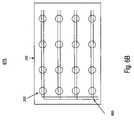
- FIG. 6Ashows a side view of a reverse mounted light array in accordance with an embodiment of the present invention.
- FIG. 6Bshows a reverse side view of a reverse mounted light array in accordance with an embodiment of the present invention.
- FIG. 7Ashows a side view of a reverse mounted light array with optical dome in accordance with one embodiment of the present invention.
- FIG. 7Bshows a side view of light emission device including a reflector cup in accordance with an embodiment of the present invention.
- FIG. 7Cshows a side view of a reverse mounted light array with optical dome in accordance with another embodiment of the present invention.
- FIG. 8shows a top view of a reverse mounted light array in accordance with an embodiment of the present invention.
- FIG. 9is a flowchart showing a process for generating a light emission device in accordance with an embodiment of the present invention.
- the present inventionprovides a reverse mounted flexible light array having a variety of applications, such as for the treatment of hyperbilirubinemia in neonates, and psoriasis, seasonal affective disorder, sleep disorders, herpes, acne, skin cancer, and other medical conditions.
- the inventionis an advance over current fiber-optic type illumination panels because of the increased intensity of the light-generating sources.
- Various configurationsare described herein, none of which should be construed as particularly preferred in general.
- an illumination panel 200 of the present inventionhaving an elongate, planar, flexible body 232 is shown having a front or contact surface 234 and a back surface facing the opposite direction and not seen in FIG. 2 .
- the illumination panel 200has a rounded rectangular configuration with a length L, a width W, and a thickness T, with the length L being substantially greater than the width W, both of which are substantially greater than the thickness T.
- the proportion of these dimensionsis preferred to enable the illumination panel 200 to be wrapped around a small infant, or around the limb of an adult, and cover substantial surface area, as seen in FIGS. 3 and 5 .
- those of skill in the artwill understand that other configurations are possible.
- the illumination panel 200contains a plurality of electric light-generating sources 220 , and thus a power cable 236 attaches to a first narrow end 238 of the body 232 .
- the body 232is thicker in a region 240 adjacent to the first end 238 to provide strain relief at the interface between the body and cable 236 .
- the body 232is molded around the light-generating sources 220 and power cable 236 , with the thickened region 240 being formed accordingly.
- a higher durometer or stiffer materialmay be used on the end of the illumination panel and/or near the end of the cable to provide the strain relief.
- the illumination panel 200may include means for transferring heat away from the front surface 234 , which may involve flow of a cooling medium to interior channels formed in the body 232 .
- the jacket around the power cable 236may also provide a conduit for delivery of the cooling medium to and from the illumination panel 200 .
- the illumination panel 200is desirably at least partly surrounded with a disposable overwrap 242 as a contamination barrier between the illumination panel and the skin of the patient.
- a disposable overwrap 242may be thin biocompatible polymer, such as polyethylene, polyurethane or cellophane, and is preferably transparent (or at least translucent) so as not to substantially reduce the intensity of light transmitted to the patient.
- the overwrap 242may have heat insulating and/or light diffusing properties.
- the overwrap 242is preferably loosely fitted over the illumination panel in any form, and can be easily secured by tape, elastic or other means, and thus easily removed and disposed of for sanitary purposes. The illumination panel can then be immediately re-used with a second overwrap 242 .
- FIGS. 3 , 4 , 5 and 5 Aseveral potential configurations of the illumination panel are shown in accordance with embodiments of the present invention.
- an illumination panel 200 similar to that shown in FIG. 2is wrapped completely around the abdomen of an infant patient.
- the illumination panel 200may be secured in this position using straps, hook and pile tape, adhesive tape adhered to a disposable cover, or other such attachment means.
- a cable 236supplies electricity and cooling medium from a control housing 348 to illumination panel 200 , as mentioned above.
- FIG. 3schematically illustrates a control assembly 348 (of conventional design) providing electricity to illumination panel 200 through power conduit 236 .
- Control assembly 348also controls the operation of an active cooling system 50 including a source of cooling medium and a pump (not shown) cooling system 50 may include cooling coils or other suitable assembly for maintaining the temperature of the cooling medium or coolant at a desired level.
- a pair of conduits, in one embodiment integrated with cable 236deliver the cooling medium to the illumination panel 200 and return medium to be cooled to the system 50 .
- a single cable 236supplies power (and possibly cooling medium) to the illumination panel 200 .
- a mat-type illumination panel 200much like the illumination panel 200 illustrated in FIG. 2 , is shown wrapped around the patient's limb and fastened with hook/loop fastener patches 566 . Again, a single conduit 236 delivers power and potentially cooling medium to the illumination panel 200 .
- the illumination panelmay be formed into a variety shapes, such as a pad or mat shown, and may be formed into any suitable configuration to treat various medical conditions, as described herein, while also protecting the patient from unwanted, and possibly harmful exposure to light and/or heat.
- the present illumination panelscan be configured to be placed on the face, like a washcloth, for the treatment of seasonal affective disorder, as well as acne and other skin conditions; or can be configured similarly to a sanitary napkin, tampon or condom for the treatment of herpes.
- the illumination panelcan be formed into a belt, a wrap, a cushion or pillow, a collar, a blanket, a strap, a vest, or any other desired shape.
- the particular shape and ultimate configuration on the patientdoes not affected the quality and intensity of the light delivered, as with prior fiber optic devices.
- the forms of the present illumination panels illustratedare not intended, and should not be taken, to be limiting.
- a phototherapy device 600includes a substrate 232 with a conductive trace 630 coupled therewith and at least one light generating source 220 reversely coupled therewith.
- the various attributes of the phototherapy device 600will now be described, followed by a more detailed description of a number of exemplary embodiments. In some cases, the phototherapy device is termed a “reverse mounted light array” herein.
- the reverse mounted light array 600has a substrate 232 having at least one electrically powered light-generating source thereon.
- the substrate 232may be variety of forms, typically including an insulating body on or in which a plurality of conductive leads or traces are provided.
- the light-generating source 220is reversely mounted to the insulating body in electrical communication with the conductive traces 630 .
- the present inventionutilizes any type of substrate 232 circuitry 630 known in the arts including flexible substrate 232 circuitry 630 .
- the term “flexible substrate”pertains to polymeric sheets, which may be bent or rolled without breaking.
- the substrate 232may be said to be flexible if it can be rolled, without breaking, into a cylindrical tube having a diameter less than 30 cm, and in some cases less than 5 cm.
- Examples of such flexible substrates 232are flexible printed circuitry laminates, which are composite of metal conductors and dielectric substrates bonded together by an adhesive system.
- Other flexible substratesmay not use adhesive, such as copper foil, which is electrolytically deposited or rolled-annealed.
- the substrate 232should be flexible and capable of withstanding the heat generated during the manufacturing process and by the light-generating sources. Consideration should also be given to the dimensional stability, chemical resistance, electrical properties, flame retardancy, and cost.
- Substratecan be either thermosetting or thermoplastic polymers, such as polyester and polyamide films. DuPont Kapton® and similar films are often utilized.
- the substrate 232may be coated, cast, deposited, or otherwise adhered to the conductive tracing 630 or vice versa.
- the conductive tracings 630are directly adjacent to and in contact with the substrate 232 .
- one or more additional layersmay be present between the conductive traces 630 and flexible substrate 232 , such as when adhesive are used.
- the conductive tracings 630may include a variety of materials, including rolled-annealed copper, electro-deposited copper, silver, nickel, gold, aluminum, iron, steel, solder, or any other metal or conductor.
- the conductive coatingmay be applied as, processed into, tracings using any means for application or removal, including chemical, mechanical, and optical means, as well as the use of lasers.
- holesare formed in the flexible substrate 232 and each LED 220 is fitted into the hole in the substrate and mounted on the tracks on the reverse 635 of flexible substrate 232 .
- Solder pasteis deposited on the exact locations of the anode and cathode tracks using, for example, screening techniques.
- Thermally conductive glueis also applied to the conductive trace 630 using, for example, dispensing technique.
- the LED 220is then coupled with the respective conductive trace 630 , with the anode and cathode terminals of the LED 220 corresponding to the solder paste deposited on the anode and cathode tracks of conductive trace 630 .
- the LED 220is subsequently secured on the conductive trace 630 by any one or more of the plurality of well known light source securing methods. For example, by re-flow soldering of the solder paste and curing the thermally conductive glue, respectively.
- a plurality of pairs of parallel conductive tracesare etched into the rolled-annealed copper coating of a flexible substrate, for example, using conventional photo-etching techniques.
- Polymer thick filmsincluding one or more finely divided conductive materials like silver, nickel, or carbon in a polymer binder like polyester, epoxy, acrylic, or vinyl also may be used.
- Polymer thick film printed wiringis less expensive than copper conductors since it is generally formed in a single step using screen printing, without traditional plating, etching, stripping, and cleaning. Examples of polymer thick films which offer an alternative to other types of circuitry are available from DuPont as the CB® series polymer thick film pastes.
- the light-generating source 220is a light-emitting diode (LED) chip or die of the reverse mount variety.
- LEDlight-emitting diode
- Reverse mounted LEDsare known in the art.
- Exemplary off-the-shelf reverse mount LEDs which can be implemented as part of embodiments of the present inventioninclude but are not limited to HSMx-C4A0 LED manufactured and sold by Agilent Technologies, Inc.; SML-811 series light emitting diodes by Rohm; and reverse-mount L-193 series by LEDopto.
- the light-generating source 220may be a light emitting device consisting of a light emitting diode mounted in a cup with electrodes electrically connected and molding material (forming an optical dome or acting as encapsulating material) covering the light emitting diode.
- a light emitting diodemounted in a cup with electrodes electrically connected and molding material (forming an optical dome or acting as encapsulating material) covering the light emitting diode.
- other types of reverse mounted LEDs, reverse mounted lasers, and reverse mounted laser diodesmay be used.
- the light-generating source 220may be multicolored LEDs, or a combination of multiple colored LEDs, a combination of different LEDs, or arrangement of the same type of LEDs, depending on the desired color, distribution or pattern.
- the preferred color of LEDsis blue, although green LEDs also may be effective.
- the treatment of other conditionsmay require different colored LEDs.
- herpesmay be most effectively treated by red LEDs
- seasonal affective disordermay be treated by white or yellow LEDs
- psoriasismay be treated by ultraviolet LEDs.
- a heat sink 640may be added to the rear of the light source 220 to increase the heat disposition.
- the problems of dissipation of heat from the light source 220is greatly reduced in comparison with the surface mount formation. That is, because the light source 220 , and therefore the heat sink 640 , is mounted at the back of the substrate 232 (e.g., the side furthest from the user) the heat sink 640 is exposed to the environment thereby increasing its heat disposition capabilities.
- the heat sink 640is a copper tap.
- the heat sink 640is a circle of copper (or other material) that can be easily attached (e.g., glued, soldered, welded, threaded, stamped, etc.) to the back of light source 220 .
- heat sink 640is stated as a copper tap, heat sink 640 may be made of any thermally dissipating material. Additionally, heat sink 640 may be made of material that is not electrically conductive.
- the heat sink 640may be attached to the reflector cup 770 of light source 220 .
- the heat sink 640 contacting the reflector cup 770(of FIG. 7C ) will dissipate the generated heat from the light source 220 via the reflector cup 770 through the heat sink 640 and then to the environment. Due to the increase in heat disposition, a plurality of valuable results may be obtained. For example, since more heat can be dissipated, than by a surface mount light source, the light source 220 of the present invention can be operated at higher power without transferring more heat to the user. Additionally, the need for a silicone coating between the entire substrate 232 and the user is no longer necessary.
- the reverse mounted LEDmay be a package LED 780 .
- the package LED 780may be initially manufactured as one device having a heat sink 640 attached to the reflector cup 770 of light source 220 . Thereby making LED package 780 a single manufactured device.
- the reverse mounted light array 600may include any suitable interconnect technology to provide an electrical circuit among the LEDs, the substrate, the power supply, and any control device.
- suitable interconnect technologyto provide an electrical circuit among the LEDs, the substrate, the power supply, and any control device.
- flexible or traditional wiring, solder attachment, conductive pieces, and/or pressure connectorsmay be used.
- the reverse mounted light array 600may also include a controller capable of making the light-generating sources 220 separately addressable so that they may be selectively illuminated in a particular pattern to achieve a particular therapeutic result.
- the power level of one or all of the light-generating sources 220may be controlled to optimize the light intensity required, to mix colors where different LEDs are used, or to shut off light-generating sources 220 in the case of overheating.
- thermocouplesmay be provided in and around the light-generating sources 220 , or on the contact surface 234 , to monitor the temperature of the reverse mounted light array.
- the reverse mounted light arraymay contain a timer to assist in metering exposure of the patient according to doctor's instructions.
- an epoxy castmay be formed into a shape, such as a dome, and used for directing light.
- Optical dome 750is optically designed based on a software simulation to design the best shape for directing, magnifying, spreading, or otherwise managing the light emitted from the light source 220 and/or reflector cup 770 .
- optical dome 750is a round shape dome. It should be appreciated that optical dome 750 may be any shape (e.g., rectangular, triangular, cylindrical), and is not limited to the illustrated embodiment.
- the reverse mounted LEDmay be a package LED 780 .
- the package LED 780may be initially manufactured as one device having a heat sink 640 attached to the reflector cup 770 of light source 220 and an optical dome 750 above the reflector cup 770 and light source 220 . That is, the LED package is a single manufactured device having a plurality of built in non-removable components.
- optical dome 750is circular to provide symmetric viewing angles of emitted light in all directions.
- optical dome 750is an oval shaped epoxy dome.
- the light source 220provides asymmetric viewing angles of emitted light in all directions.
- the viewing angle on the horizontal axisis greater than the viewing angle on the vertical axis.
- the LEDcan be any known LED, for example, an HSMx-C4A0 LED manufactured and sold by Agilent Technologies, Inc.
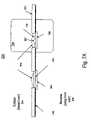
- Light emission device 760comprises light source 220 , wire bond 710 , and a lead frame comprising first lead frame segment 715 and second lead frame segment 720 .
- Light source 220 , wire bond 710 and at least a portion of the lead frameare encased in epoxy cast optical dome 750 .
- a lead framerefers to a type of chip package that uses conductive leads that extend outside of a housing.
- a portion of first lead frame segment 715 and a portion of second lead frame segment 720are not encased within epoxy cast optical dome 750 , allowing for the transmission of power signals to light source 220 .
- the lead frameis comprised of copper, however, it should be appreciated that any other conductive material, such as another metal, may be implemented.
- the lead frameis covered in a plating to improve various properties of the lead frame. For example, plating may be used to improve the bonding strength between light source 220 and first lead frame segment 715 and between wire bond 710 and second lead frame segment 720 , may enhance the adhesiveness of epoxy cast optical dome 750 to the lead frame, may prevent oxidization of a metal lead frame, may enhance to solderability of pads of first lead frame segment 715 and second lead frame segment 720 , and can improve the surface reflectivity to enhance flux extraction.
- the platingis nickel/palladium/gold (NiPdAu).
- the platingis silver (Ag). It should be appreciated that any other plating material may be implemented depending on the design requirements of light emission device 760 .
- a lead frameprovides improved thermal dissipation over the use of a PCB substrate, due to the lower thermal resistance.
- Light emission device 760can be subjected to higher operating current due to the better heat dissipation properties of the lead frame. Therefore, the luminous intensity of light emission device 760 can be increased.
- light emission device 760may have a lower profile due to a lead frame being thinner than a PCB substrate.
- Light source 220is coupled to first lead frame segment 715 .
- a power signalis received at light source 220 from first lead frame segment 715 .
- light source 220is a light emitting diode (LED) die. While embodiments of the invention are described using an LED, it should be appreciated that other types of light sources may be implemented, such as an infrared emitting diode (IRED) or a laser diode.
- Wire bond 710is coupled to light source 220 and second lead frame segment 720 . Light source 220 receives positive and negative power signals via first lead frame segment 715 and wire bond 710 , and emits light in response to such signals. In one embodiment, wire bond 710 is a gold wire.
- first lead frame segment 715operates as a cathode for transmitting a negative power signal
- second lead frame 720operates as an anode for transmitting a positive power signal, as indicated at anode mark 730 .
- Epoxy cast optical dome 750is formed over light source 220 , wire bond 710 , a portion of first lead frame segment 715 and an portion of second lead frame segment 720 using an epoxy casting process.
- the use of a conductive lead frame substrateprovides for the use of a conventional casting process in forming epoxy cast optical dome 750 .
- epoxy cast optical dome 750is comprised of substantially half epoxy resin and substantially half epoxy hardener. However, it should be appreciated that any combination of epoxy resin and epoxy hardener may be used.
- Epoxy cast optical dome 750is translucent, allowing for the passage of light.
- epoxy cast optical dome 750comprises a color tinting for filtering the wavelength of light passing through epoxy cast optical dome 750 .
- epoxy cast optical dome 750is operable to diffuse light passing through epoxy cast optical dome 750 .
- Using a casting process to generate epoxy cast optical dome 750provides a substantial cost savings over transfer molding process due to the high volume per run with high density lead frame design as well as lower initial tooling costs.
- epoxy cast optical dome 750provides improved moisture absorption resistivity compared to molding compound which is more sensitive to moisture.
- Light emission device 760comprises reflector cup 770 for receiving light source 220 and for reflecting light emitted from light source 220 .
- light source 220resides at least partially within reflector cup 770 . Placing light source 220 within reflector cup 770 allows for enhancing and directing the light emitted by light source 220 . Furthermore, placing light source 220 within reflector cup 770 assists in providing a low profile for light emission device 760 , thereby allowing wider applicability.
- Epoxy cast optical dome 750comprises epoxy shaped portion 730 .
- shaped portion 730is a round shape dome. It should be appreciated that epoxy shaped portion 730 may be any shape and is not limited to the illustrated embodiment.
- the use of reflector cup 770 in conjunction with epoxy shaped portion 730allows for directing the light emitted in a desired radiation pattern and viewing angle.
- embodiments of the present inventionare configured to implement different types of light sources.
- embodiments of the present inventionmay implement a double wire bonded light source (e.g., a double wire bonded LED).
- a double wire bonded light sourceis operable to receive positive and negative power signals through two wire bonds, respectively, rather than through one wire bond and through coupling the light source to a lead frame.
- the interfacecauses the light emitted by the plurality of light-generating sources to be diffused or directed as desired such as shown in FIG. 8 .
- Such diffusion or directionis effective to provide a more uniform, constant and intense light pattern on the contact surface relative to a similar apparatus including a plurality of discrete light emitting sources without light diffusion.
- the interfacemay be made of a single material or blend of materials having different refractive indices, such as silicone and glass bubbles or silicone and titania, or may include other materials, such as metals, to reflect or block light.
- an outer covering or an internal layer with deformities or markings formed by mechanical, chemical, or other means to cause light emitted by the light-generating sources 220 to diffuseis not necessary and further reduces the manufacturing and post-manufacturing processing of the reverse mounted light array.
- an optional silicone coating 790is shown above the optical dome 750 .
- the silicone coating 790is used to reduce heat transfer from the light source 220 to the user. Therefore, the silicone coating is just placed above the light source 220 .
- the entire front side of the substrate 232does not need to be coated in silicone or any other non-conductive material. Since there is no circuitry on the side of the substrate that is facing the user, there is no need to insulate the front side of the substrate 232 from any type of short circuit. Additionally, there is no need to provide a silicone (or other non-conductive bio or non-biometric material) for the protection and/or safety of the user. Therefore, a savings in both manufacture time and cost may be realized.
- the manufacturernot only realizes a manufacturing cost and time savings, problems inherent with the use of an over-coating are reduced. For example, there is no warping of the substrate 232 due to the heating and cooling of the over-coating material. The substrate 232 may be bent both backward and inward without damaging the substrate 232 . There is no worry of discoloration or wear of the over-coating material. Additionally, there are no bubbles or light losses due to light absorption of the over-coating material.
- the reverse side of substrate 232is covered with an insulation layer 242 such as a cloth layer or other non-conductive material to reduce patient and environment contact.
- an insulation layer 242such as a cloth layer or other non-conductive material to reduce patient and environment contact.
- this layerdiffers from the over coating of a surface mount apparatus due to the ability to change or remove the insulation layer 242 .
- the materiale.g., neoprene, wool, cotton, etc
- the insulation layer 242may be loose or tight and will have little or no effect on the overall flexibility of the reverse mounted light array 775 .
- a reverse mounted light array 800is shown according to one embodiment of the present invention.
- the light array 800shows the advantages of having the light source 220 optically shaped to provide directed light 870 . Specifically, by directing the resultant light from the plurality of light sources 220 , the reverse mounted light array 800 will reduce light dissipation thereby increasing efficiency and decreasing power consumption.
- FIG. 9a flow chart showing a process for generating a light emission device in accordance with an embodiment of the present invention.
- a reverse mounted light generating sourceis coupled with a substrate.
- the substrate 232is a flexible substrate such as a flexible circuit, flexible metal frame, or the like, made of polyimide material or the like.
- the substrateis an electrically non-conductive but thermally conductive flexible material.
- the light source 220is a low profile, small footprint, high brightness, and high radiometric power light source having a wide viewing angle.
- the light source 220is a light emitting diode (LED), a laser, an organic light emitting diode, or a laser diode, or the like.
- the light source 220may be multicolored, a combination of multiple colors, a combination of different light sources 220 , or an arrangement of the same type of light sources 220 .
- the pattern and combination of the light source 220may be modified depending on desired color, distribution, or use of the array 600 .
- the light generating sources 220may be attached or embedded into the substrate 232 .
- Embodiments of the present inventionare configured to implement different types of light sources.
- embodiments of the present inventionmay implement a double wire bonded light source (e.g., a double wire bonded LED).
- a double wire bonded light sourceis operable to receive positive and negative power signals through two wire bonds, respectively, rather than through one wire bond and through coupling the light source to a lead frame.
- an electrical portion of the reverse mounted light generating sourceis coupled with a conductive trace coupled to the reverse side of the substrate, wherein the coupling of the conductive trace with the substrate and the reverse mounted light generating source forms a reverse mounted light array.
- a plurality of conductive traces 630are formed on the substrate 232 layer.
- the conductive trace 630may be flexible.
- a plurality of discrete light sources 220may be arranged along the electrical tracks on the flexible substrate layer and may be electrically connected with the electrical tracks of conductive trace 630 such that it is both thin and flexible.
- embodiments of the inventionprovide a reverse mounted flexible light array that provides higher operating conditions with better heat dissipation. Furthermore, the reverse mounted flexible light array has improved light management due to the use of directed light technology. The described embodiments also provide a reverse mounted flexible light array that provides higher light output due to the improved heat dissipation, as well as a higher reflective surface, a reflector cup, and a shaped epoxy dome.
Landscapes
- Engineering & Computer Science (AREA)
- Health & Medical Sciences (AREA)
- Biomedical Technology (AREA)
- General Health & Medical Sciences (AREA)
- Veterinary Medicine (AREA)
- Radiology & Medical Imaging (AREA)
- Life Sciences & Earth Sciences (AREA)
- Animal Behavior & Ethology (AREA)
- Pathology (AREA)
- Public Health (AREA)
- Nuclear Medicine, Radiotherapy & Molecular Imaging (AREA)
- Physics & Mathematics (AREA)
- Microelectronics & Electronic Packaging (AREA)
- Optics & Photonics (AREA)
- General Engineering & Computer Science (AREA)
- Non-Portable Lighting Devices Or Systems Thereof (AREA)
- Arrangement Of Elements, Cooling, Sealing, Or The Like Of Lighting Devices (AREA)
Abstract
Description
Claims (34)
Priority Applications (1)
| Application Number | Priority Date | Filing Date | Title |
|---|---|---|---|
| US10/833,905US7210817B2 (en) | 2004-04-27 | 2004-04-27 | Method, system and device for delivering phototherapy to a patient |
Applications Claiming Priority (1)
| Application Number | Priority Date | Filing Date | Title |
|---|---|---|---|
| US10/833,905US7210817B2 (en) | 2004-04-27 | 2004-04-27 | Method, system and device for delivering phototherapy to a patient |
Publications (2)
| Publication Number | Publication Date |
|---|---|
| US20050237739A1 US20050237739A1 (en) | 2005-10-27 |
| US7210817B2true US7210817B2 (en) | 2007-05-01 |
Family
ID=35136183
Family Applications (1)
| Application Number | Title | Priority Date | Filing Date |
|---|---|---|---|
| US10/833,905Expired - LifetimeUS7210817B2 (en) | 2004-04-27 | 2004-04-27 | Method, system and device for delivering phototherapy to a patient |
Country Status (1)
| Country | Link |
|---|---|
| US (1) | US7210817B2 (en) |
Cited By (38)
| Publication number | Priority date | Publication date | Assignee | Title |
|---|---|---|---|---|
| US20050222561A1 (en)* | 2002-04-24 | 2005-10-06 | Hilal Said S | Surgical digitizing apparatus and method |
| US20060100675A1 (en)* | 2004-11-09 | 2006-05-11 | Steven Gardner | Device and method for phototherapy of jaundiced infants |
| US20070276456A1 (en)* | 2003-07-16 | 2007-11-29 | Hwa-Soo Hwang | Band for Curing Human Body |
| US20080192493A1 (en)* | 2007-02-12 | 2008-08-14 | Cree, Inc. | High thermal conductivity packaging for solid state light emitting apparatus and associated assembling methods |
| US20090002986A1 (en)* | 2007-06-27 | 2009-01-01 | Cree, Inc. | Light Emitting Device (LED) Lighting Systems for Emitting Light in Multiple Directions and Related Methods |
| US20090002979A1 (en)* | 2007-06-27 | 2009-01-01 | Cree, Inc. | Light emitting device (led) lighting systems for emitting light in multiple directions and related methods |
| US20090108777A1 (en)* | 2007-10-30 | 2009-04-30 | Searete Llc, A Limited Liability Corporation Of The State Of Delaware | Devices and systems that deliver nitric oxide |
| US20090110612A1 (en)* | 2007-10-30 | 2009-04-30 | Searete Llc, A Limited Liability Corporation Of The State Of Delaware | Nitric oxide permeable housings |
| US20090112193A1 (en)* | 2007-10-30 | 2009-04-30 | Searete Llc, A Limited Liability Corporation Of The State Of Delaware | Systems and devices that utilize photolyzable nitric oxide donors |
| US20090112295A1 (en)* | 2007-10-30 | 2009-04-30 | Searete Llc, A Limited Liability Corporation Of The State Of Delaware | Devices and systems that deliver nitric oxide |
| US20090110712A1 (en)* | 2007-10-30 | 2009-04-30 | Searete Llc, A Limited Liability Corporation Of The State Of Delaware | Methods and systems for use of photolyzable nitric oxide donors |
| US20090110958A1 (en)* | 2007-10-30 | 2009-04-30 | Searete Llc, A Limited Liability Corporation Of The State Of Delaware | Systems and devices that utilize photolyzable nitric oxide donors |
| US20090112055A1 (en)* | 2007-10-30 | 2009-04-30 | Searete Llc, A Limited Liability Corporation Of The State Of Delaware | Sleeves configured to facilitate release of nitric oxide |
| US20090110933A1 (en)* | 2007-10-30 | 2009-04-30 | Searete Llc, A Limited Liability Corporation Of The State Of Delaware | Systems and devices related to nitric oxide releasing materials |
| US20100106228A1 (en)* | 2008-10-27 | 2010-04-29 | Steven Gardner | Device and method of phototherapy for jaundiced infants |
| US20100241196A1 (en)* | 2009-03-19 | 2010-09-23 | Tyco Healthcare Group Lp | Phototherapy wound treatment |
| US7897399B2 (en) | 2007-10-30 | 2011-03-01 | The Invention Science Fund I, Llc | Nitric oxide sensors and systems |
| US7975699B2 (en) | 2007-10-30 | 2011-07-12 | The Invention Science Fund I, Llc | Condoms configured to facilitate release of nitric oxide |
| US20110190604A1 (en)* | 2006-12-22 | 2011-08-04 | Hyde Roderick A | Nitric oxide sensors and systems |
| US8096671B1 (en) | 2009-04-06 | 2012-01-17 | Nmera, Llc | Light emitting diode illumination system |
| US8240875B2 (en) | 2008-06-25 | 2012-08-14 | Cree, Inc. | Solid state linear array modules for general illumination |
| US20120253432A1 (en)* | 2009-12-16 | 2012-10-04 | Koninklijke Philips Electronics N.V. | Light treatment system |
| US20130178919A1 (en)* | 2010-07-22 | 2013-07-11 | Andrew McNeill | Disposable skin care device |
| US20140031906A1 (en)* | 2012-07-26 | 2014-01-30 | Donna J. BREZINSKI | Portable phototherapy device |
| US20140066974A1 (en)* | 2011-05-16 | 2014-03-06 | Color Seven Co., Ltd. | Menstrual pain treatment device |
| USD722383S1 (en) | 2012-05-01 | 2015-02-10 | Carol Cole Company | Skin clearing and toning device |
| US8980332B2 (en) | 2007-10-30 | 2015-03-17 | The Invention Science Fund I, Llc | Methods and systems for use of photolyzable nitric oxide donors |
| USD739541S1 (en) | 2014-05-12 | 2015-09-22 | Carol Cole Company | Skin clearing and toning device |
| US9295854B2 (en) | 2012-11-28 | 2016-03-29 | Point Source, Inc. | Light and bioelectric therapy pad |
| US10004919B2 (en) | 2012-07-03 | 2018-06-26 | Koninklijke Philips N.V. | Phototherapy patch with increased thermal insulation |
| US10080823B2 (en) | 2007-10-30 | 2018-09-25 | Gearbox Llc | Substrates for nitric oxide releasing devices |
| US10180248B2 (en) | 2015-09-02 | 2019-01-15 | ProPhotonix Limited | LED lamp with sensing capabilities |
| US10286226B2 (en) | 2013-09-18 | 2019-05-14 | D-Rev: Design For The Other Ninety Percent | Phototherapy device for the treatment of hyperbilirubinemia |
| USD854699S1 (en) | 2018-05-15 | 2019-07-23 | Carol Cole Company | Elongated skin toning device |
| USD891628S1 (en) | 2015-03-03 | 2020-07-28 | Carol Cole Company | Skin toning device |
| US11103724B2 (en) | 2017-01-04 | 2021-08-31 | Arbor Grace, Inc. | Photo-treatment device |
| USD953553S1 (en) | 2020-02-19 | 2022-05-31 | Carol Cole Company | Skin toning device |
| USD957664S1 (en) | 2020-07-29 | 2022-07-12 | Carol Cole Company | Skin toning device |
Families Citing this family (49)
| Publication number | Priority date | Publication date | Assignee | Title |
|---|---|---|---|---|
| US7145125B2 (en) | 2003-06-23 | 2006-12-05 | Advanced Optical Technologies, Llc | Integrating chamber cone light using LED sources |
| US7521667B2 (en) | 2003-06-23 | 2009-04-21 | Advanced Optical Technologies, Llc | Intelligent solid state lighting |
| US20070115686A1 (en)* | 2005-11-23 | 2007-05-24 | Luc Tyberghien | Lighting assembly, backlight assembly, display panel, and methods of temperature control |
| WO2007075742A2 (en)* | 2005-12-21 | 2007-07-05 | Cree Led Lighting Solutions, Inc. | Lighting device |
| EP1839705A1 (en)* | 2006-03-27 | 2007-10-03 | Universidad de Alcala | Transcutaneous laser therapy patch |
| US7648257B2 (en) | 2006-04-21 | 2010-01-19 | Cree, Inc. | Light emitting diode packages |
| US7625103B2 (en)* | 2006-04-21 | 2009-12-01 | Cree, Inc. | Multiple thermal path packaging for solid state light emitting apparatus and associated assembling methods |
| US7777166B2 (en)* | 2006-04-21 | 2010-08-17 | Cree, Inc. | Solid state luminaires for general illumination including closed loop feedback control |
| EP2021688B1 (en) | 2006-05-05 | 2016-04-27 | Cree, Inc. | Lighting device |
| WO2007142946A2 (en) | 2006-05-31 | 2007-12-13 | Cree Led Lighting Solutions, Inc. | Lighting device and method of lighting |
| US7665862B2 (en) | 2006-09-12 | 2010-02-23 | Cree, Inc. | LED lighting fixture |
| US7766508B2 (en)* | 2006-09-12 | 2010-08-03 | Cree, Inc. | LED lighting fixture |
| CN101675298B (en)* | 2006-09-18 | 2013-12-25 | 科锐公司 | Lighting device, lighting device combination, lamp and method of use thereof |
| TW200837308A (en)* | 2006-09-21 | 2008-09-16 | Led Lighting Fixtures Inc | Lighting assemblies, methods of installing same, and methods of replacing lights |
| GB0620436D0 (en)* | 2006-10-14 | 2006-11-22 | Cyden Ltd | Apparatus and method for stimulation of cartilage |
| KR101513738B1 (en)* | 2006-11-14 | 2015-04-21 | 크리, 인코포레이티드 | Lighting assemblies and components for lighting assemblies |
| US9605828B2 (en)* | 2006-11-14 | 2017-03-28 | Cree, Inc. | Light engine assemblies |
| WO2008097062A1 (en)* | 2007-02-06 | 2008-08-14 | Kim, Tae Gyu | Photochemistry laser diode assembly and photochemistry sheet having the same |
| US7824070B2 (en) | 2007-03-22 | 2010-11-02 | Cree, Inc. | LED lighting fixture |
| US7967480B2 (en)* | 2007-05-03 | 2011-06-28 | Cree, Inc. | Lighting fixture |
| CN101790660B (en)* | 2007-05-07 | 2013-10-09 | 科锐公司 | Lamps and lighting fixtures |
| WO2009012287A1 (en) | 2007-07-17 | 2009-01-22 | Cree Led Lighting Solutions, Inc. | Optical elements with internal optical features and methods of fabricating same |
| US8104911B2 (en) | 2007-09-28 | 2012-01-31 | Apple Inc. | Display system with distributed LED backlight |
| KR100900248B1 (en)* | 2008-03-17 | 2009-06-01 | 주식회사 큐레이 | Backlight unit with health care role |
| US8461613B2 (en)* | 2008-05-27 | 2013-06-11 | Interlight Optotech Corporation | Light emitting device |
| CN101603636B (en)* | 2008-06-10 | 2012-05-23 | 展晶科技(深圳)有限公司 | Light source device |
| DE102009032606A1 (en)* | 2009-07-10 | 2011-01-13 | Osram Opto Semiconductors Gmbh | Optoelectronic component and flat light source |
| US10384076B2 (en)* | 2010-08-17 | 2019-08-20 | Koninklijke Philips N.V. | Flexible light therapy device, a plaster and a bandage |
| US8944632B2 (en)* | 2010-10-15 | 2015-02-03 | Douglas Tveit | LED lighting system and method for external surfaces |
| CA2844135A1 (en)* | 2011-08-01 | 2013-02-07 | Infrared Imaging Systems, Inc. | Disposable light source for enhanced visualization of subcutaneous structures |
| RU2608903C2 (en)* | 2011-09-26 | 2017-01-26 | Конинклейке Филипс Н.В. | Heat recovering system for phototherapy device |
| US20140350454A1 (en)* | 2011-12-19 | 2014-11-27 | Photocure Asa | Irradiation apparatus |
| US20130163272A1 (en)* | 2011-12-23 | 2013-06-27 | Touchsensor Technologies, Llc | User interface lighting apparatus |
| US10004917B2 (en)* | 2013-07-11 | 2018-06-26 | Board Of Trustees Of Michigan State University | Neural prosthetic device and method of making same |
| KR101602259B1 (en)* | 2013-11-12 | 2016-03-10 | 주식회사 피치텍 | Led pad, manufacturing method of the led pad and personal therapy apparatus comprising the led pad |
| JP6225812B2 (en) | 2014-04-18 | 2017-11-08 | 日亜化学工業株式会社 | Light emitting device |
| US9714746B2 (en) | 2014-04-29 | 2017-07-25 | Cooledge Lighting Inc. | Modular LED lighting systems |
| FR3034167B1 (en)* | 2015-03-23 | 2018-05-18 | Lucibel | DEFORMABLE LIGHT DEVICE |
| US9735089B2 (en)* | 2015-09-24 | 2017-08-15 | Intel Corporation | Thermal management for flexible integrated circuit packages |
| US9971235B2 (en)* | 2016-01-29 | 2018-05-15 | Seiko Epson Corporation | Light source device, projector, and method of manufacturing light source device |
| US10344954B1 (en) | 2016-03-02 | 2019-07-09 | Cooledge Lighting Inc. | Lighting systems incorporating connections for signal and power transmission |
| US10746358B1 (en) | 2016-03-02 | 2020-08-18 | Cooledge Lighting Inc. | Lighting systems incorporating connections for signal and power transmission |
| US11274823B1 (en) | 2016-03-02 | 2022-03-15 | Cooledge Lighting, Inc. | Lighting systems incorporating connections for signal and power transmission |
| US11056629B2 (en) | 2017-03-21 | 2021-07-06 | Lumileds Llc | Mounting an LED element on a flat carrier |
| US11458328B2 (en) | 2018-10-22 | 2022-10-04 | Joovv, Inc. | Photobiomodulation therapy device accessories |
| US11033752B2 (en)* | 2018-10-22 | 2021-06-15 | Joovv, Inc. | Photobiomodulation therapy systems and methods |
| US10478635B1 (en) | 2018-10-22 | 2019-11-19 | Joovv, Inc. | Photobiomodulation therapy systems and methods |
| FR3087662B1 (en)* | 2018-10-31 | 2020-10-23 | Mdb Texinov | DEVICE FOR THE TREATMENT OF PATIENTS BY PHOTOTHERAPY |
| US11904178B2 (en)* | 2022-02-25 | 2024-02-20 | Biothread Llc | Light therapy wearable with jacketed side-emitting optical fiber |
Citations (7)
| Publication number | Priority date | Publication date | Assignee | Title |
|---|---|---|---|---|
| US6290713B1 (en)* | 1999-08-24 | 2001-09-18 | Thomas A. Russell | Flexible illuminators for phototherapy |
| US20040138726A1 (en)* | 2003-01-09 | 2004-07-15 | Savage Henry C. | Portable light delivery apparatus and methods for delivering light to the human body |
| US20040149998A1 (en)* | 2002-12-02 | 2004-08-05 | Henson Gordon D. | Illumination system using a plurality of light sources |
| WO2004087793A1 (en)* | 2003-03-28 | 2004-10-14 | Pi R & D Co. Ltd. | Crosslinked polyimide, composition comprising the same and method for producing the same |
| US6871981B2 (en)* | 2001-09-13 | 2005-03-29 | Heads Up Technologies, Inc. | LED lighting device and system |
| US6945672B2 (en)* | 2002-08-30 | 2005-09-20 | Gelcore Llc | LED planar light source and low-profile headlight constructed therewith |
| US6999318B2 (en)* | 2003-07-28 | 2006-02-14 | Honeywell International Inc. | Heatsinking electronic devices |
- 2004
- 2004-04-27USUS10/833,905patent/US7210817B2/ennot_activeExpired - Lifetime
Patent Citations (7)
| Publication number | Priority date | Publication date | Assignee | Title |
|---|---|---|---|---|
| US6290713B1 (en)* | 1999-08-24 | 2001-09-18 | Thomas A. Russell | Flexible illuminators for phototherapy |
| US6871981B2 (en)* | 2001-09-13 | 2005-03-29 | Heads Up Technologies, Inc. | LED lighting device and system |
| US6945672B2 (en)* | 2002-08-30 | 2005-09-20 | Gelcore Llc | LED planar light source and low-profile headlight constructed therewith |
| US20040149998A1 (en)* | 2002-12-02 | 2004-08-05 | Henson Gordon D. | Illumination system using a plurality of light sources |
| US20040138726A1 (en)* | 2003-01-09 | 2004-07-15 | Savage Henry C. | Portable light delivery apparatus and methods for delivering light to the human body |
| WO2004087793A1 (en)* | 2003-03-28 | 2004-10-14 | Pi R & D Co. Ltd. | Crosslinked polyimide, composition comprising the same and method for producing the same |
| US6999318B2 (en)* | 2003-07-28 | 2006-02-14 | Honeywell International Inc. | Heatsinking electronic devices |
Non-Patent Citations (1)
| Title |
|---|
| Northpoint Technologies, INC. Flexible Circuits [online], [retrieved on Feb. 18, 2006]. Rerieved from the Internet <http://web.archive.org/web/20031030104520/http://www.flexcircuitsinc.com/benefits.htm>.* |
Cited By (61)
| Publication number | Priority date | Publication date | Assignee | Title |
|---|---|---|---|---|
| US7740625B2 (en)* | 2002-04-24 | 2010-06-22 | Applied Medical Resources Corporation | Surgical digitizing apparatus and method |
| US20050222561A1 (en)* | 2002-04-24 | 2005-10-06 | Hilal Said S | Surgical digitizing apparatus and method |
| US20070276456A1 (en)* | 2003-07-16 | 2007-11-29 | Hwa-Soo Hwang | Band for Curing Human Body |
| US20060100675A1 (en)* | 2004-11-09 | 2006-05-11 | Steven Gardner | Device and method for phototherapy of jaundiced infants |
| US20110190604A1 (en)* | 2006-12-22 | 2011-08-04 | Hyde Roderick A | Nitric oxide sensors and systems |
| US20080192493A1 (en)* | 2007-02-12 | 2008-08-14 | Cree, Inc. | High thermal conductivity packaging for solid state light emitting apparatus and associated assembling methods |
| US8258682B2 (en) | 2007-02-12 | 2012-09-04 | Cree, Inc. | High thermal conductivity packaging for solid state light emitting apparatus and associated assembling methods |
| US20090002986A1 (en)* | 2007-06-27 | 2009-01-01 | Cree, Inc. | Light Emitting Device (LED) Lighting Systems for Emitting Light in Multiple Directions and Related Methods |
| US20090002979A1 (en)* | 2007-06-27 | 2009-01-01 | Cree, Inc. | Light emitting device (led) lighting systems for emitting light in multiple directions and related methods |
| US8210717B2 (en) | 2007-06-27 | 2012-07-03 | Cree, Inc. | Light emitting device (LED) lighting systems for emitting light in multiple directions and related methods |
| US8042971B2 (en) | 2007-06-27 | 2011-10-25 | Cree, Inc. | Light emitting device (LED) lighting systems for emitting light in multiple directions and related methods |
| US20090112193A1 (en)* | 2007-10-30 | 2009-04-30 | Searete Llc, A Limited Liability Corporation Of The State Of Delaware | Systems and devices that utilize photolyzable nitric oxide donors |
| US20090112295A1 (en)* | 2007-10-30 | 2009-04-30 | Searete Llc, A Limited Liability Corporation Of The State Of Delaware | Devices and systems that deliver nitric oxide |
| US20090112055A1 (en)* | 2007-10-30 | 2009-04-30 | Searete Llc, A Limited Liability Corporation Of The State Of Delaware | Sleeves configured to facilitate release of nitric oxide |
| US20090110933A1 (en)* | 2007-10-30 | 2009-04-30 | Searete Llc, A Limited Liability Corporation Of The State Of Delaware | Systems and devices related to nitric oxide releasing materials |
| US20090108777A1 (en)* | 2007-10-30 | 2009-04-30 | Searete Llc, A Limited Liability Corporation Of The State Of Delaware | Devices and systems that deliver nitric oxide |
| US20090110712A1 (en)* | 2007-10-30 | 2009-04-30 | Searete Llc, A Limited Liability Corporation Of The State Of Delaware | Methods and systems for use of photolyzable nitric oxide donors |
| US10080823B2 (en) | 2007-10-30 | 2018-09-25 | Gearbox Llc | Substrates for nitric oxide releasing devices |
| US7846400B2 (en) | 2007-10-30 | 2010-12-07 | The Invention Science Fund I, Llc | Substrates for nitric oxide releasing devices |
| US7862598B2 (en) | 2007-10-30 | 2011-01-04 | The Invention Science Fund I, Llc | Devices and systems that deliver nitric oxide |
| US7897399B2 (en) | 2007-10-30 | 2011-03-01 | The Invention Science Fund I, Llc | Nitric oxide sensors and systems |
| US7975699B2 (en) | 2007-10-30 | 2011-07-12 | The Invention Science Fund I, Llc | Condoms configured to facilitate release of nitric oxide |
| US20090110958A1 (en)* | 2007-10-30 | 2009-04-30 | Searete Llc, A Limited Liability Corporation Of The State Of Delaware | Systems and devices that utilize photolyzable nitric oxide donors |
| US20090110604A1 (en)* | 2007-10-30 | 2009-04-30 | Searete Llc, A Limited Liability Corporation Of The State Of Delaware | Substrates for nitric oxide releasing devices |
| US8980332B2 (en) | 2007-10-30 | 2015-03-17 | The Invention Science Fund I, Llc | Methods and systems for use of photolyzable nitric oxide donors |
| US8642093B2 (en) | 2007-10-30 | 2014-02-04 | The Invention Science Fund I, Llc | Methods and systems for use of photolyzable nitric oxide donors |
| US8221690B2 (en) | 2007-10-30 | 2012-07-17 | The Invention Science Fund I, Llc | Systems and devices that utilize photolyzable nitric oxide donors |
| US8349262B2 (en) | 2007-10-30 | 2013-01-08 | The Invention Science Fund I, Llc | Nitric oxide permeable housings |
| US20090110612A1 (en)* | 2007-10-30 | 2009-04-30 | Searete Llc, A Limited Liability Corporation Of The State Of Delaware | Nitric oxide permeable housings |
| US8877508B2 (en) | 2007-10-30 | 2014-11-04 | The Invention Science Fund I, Llc | Devices and systems that deliver nitric oxide |
| US8240875B2 (en) | 2008-06-25 | 2012-08-14 | Cree, Inc. | Solid state linear array modules for general illumination |
| US8764226B2 (en) | 2008-06-25 | 2014-07-01 | Cree, Inc. | Solid state array modules for general illumination |
| US20100106228A1 (en)* | 2008-10-27 | 2010-04-29 | Steven Gardner | Device and method of phototherapy for jaundiced infants |
| US8399731B2 (en)* | 2009-03-19 | 2013-03-19 | Covidien Lp | Phototherapy wound treatment |
| US20100241196A1 (en)* | 2009-03-19 | 2010-09-23 | Tyco Healthcare Group Lp | Phototherapy wound treatment |
| US8096671B1 (en) | 2009-04-06 | 2012-01-17 | Nmera, Llc | Light emitting diode illumination system |
| US20120253432A1 (en)* | 2009-12-16 | 2012-10-04 | Koninklijke Philips Electronics N.V. | Light treatment system |
| US20130178919A1 (en)* | 2010-07-22 | 2013-07-11 | Andrew McNeill | Disposable skin care device |
| US20140066974A1 (en)* | 2011-05-16 | 2014-03-06 | Color Seven Co., Ltd. | Menstrual pain treatment device |
| USD770635S1 (en) | 2012-05-01 | 2016-11-01 | Carol Cole Company | Skin clearing and toning device |
| USD845496S1 (en) | 2012-05-01 | 2019-04-09 | Carol Cole Company | Skin clearing and toning device |
| USD722383S1 (en) | 2012-05-01 | 2015-02-10 | Carol Cole Company | Skin clearing and toning device |
| USD831835S1 (en) | 2012-05-01 | 2018-10-23 | Carol Cole Company | Skin clearing and toning device |
| US10004919B2 (en) | 2012-07-03 | 2018-06-26 | Koninklijke Philips N.V. | Phototherapy patch with increased thermal insulation |
| US20140031906A1 (en)* | 2012-07-26 | 2014-01-30 | Donna J. BREZINSKI | Portable phototherapy device |
| US9604072B2 (en)* | 2012-07-26 | 2017-03-28 | Little Sparrows Technologies Llc | Portable phototherapy device |
| US9295854B2 (en) | 2012-11-28 | 2016-03-29 | Point Source, Inc. | Light and bioelectric therapy pad |
| US10286226B2 (en) | 2013-09-18 | 2019-05-14 | D-Rev: Design For The Other Ninety Percent | Phototherapy device for the treatment of hyperbilirubinemia |
| USD739541S1 (en) | 2014-05-12 | 2015-09-22 | Carol Cole Company | Skin clearing and toning device |
| USD756527S1 (en) | 2014-05-12 | 2016-05-17 | Carol Cole Company | Skin clearing and toning device |
| USD891628S1 (en) | 2015-03-03 | 2020-07-28 | Carol Cole Company | Skin toning device |
| USD1054571S1 (en) | 2015-03-03 | 2024-12-17 | Carol Cole Company | Skin toning device |
| US10180248B2 (en) | 2015-09-02 | 2019-01-15 | ProPhotonix Limited | LED lamp with sensing capabilities |
| US11103724B2 (en) | 2017-01-04 | 2021-08-31 | Arbor Grace, Inc. | Photo-treatment device |
| USD854699S1 (en) | 2018-05-15 | 2019-07-23 | Carol Cole Company | Elongated skin toning device |
| USD949358S1 (en) | 2018-05-15 | 2022-04-19 | Carol Cole Company | Elongated skin toning device |
| USD959005S1 (en) | 2018-05-15 | 2022-07-26 | Carol Cole Company | Elongated skin toning device |
| USD953553S1 (en) | 2020-02-19 | 2022-05-31 | Carol Cole Company | Skin toning device |
| USD1047175S1 (en) | 2020-02-19 | 2024-10-15 | Carol Cole Company | Head of a skin toning device |
| USD957664S1 (en) | 2020-07-29 | 2022-07-12 | Carol Cole Company | Skin toning device |
| USD1017822S1 (en) | 2020-07-29 | 2024-03-12 | Carol Cole Company | Skin toning device |
Also Published As
| Publication number | Publication date |
|---|---|
| US20050237739A1 (en) | 2005-10-27 |
Similar Documents
| Publication | Publication Date | Title |
|---|---|---|
| US7210817B2 (en) | Method, system and device for delivering phototherapy to a patient | |
| US20240243224A1 (en) | Solid State Light Sheet Having Wide Support Substrate and Narrow Strips Enclosing LED Dies in Series | |
| EP3299063B1 (en) | Therapeutic light-emitting module | |
| CN1250302C (en) | Flexible illuminator for phototherapy | |
| US7128442B2 (en) | Illumination unit with a solid-state light generating source, a flexible substrate, and a flexible and optically transparent encapsulant | |
| JP5368277B2 (en) | Light emitting module and light source device | |
| JP4709819B2 (en) | Thin and highly efficient lighting device for use in backlighting | |
| US20070053179A1 (en) | Low profile light source utilizing a flexible circuit carrier | |
| KR101294008B1 (en) | Backlight assembly, method of manufacturing the same and display device having the same | |
| KR20070039398A (en) | Method of manufacturing semiconductor device, semiconductor module and semiconductor module | |
| JP2012134305A (en) | Light emitting device and lighting device using the light emitting device | |
| US9404626B2 (en) | Illuminating apparatus | |
| JP2010529652A (en) | Flexible circuit | |
| JP3454123B2 (en) | LED lighting module | |
| JP4143043B2 (en) | Light emitting device and lighting device | |
| KR20190056508A (en) | Stretchable patch | |
| KR20060115911A (en) | Probe | |
| KR20160025257A (en) | Led pad and personal therapy apparatus comprising the led pad | |
| JP4823304B2 (en) | LED having a wide wavelength band and photopolymerizer using the same | |
| WO2008072803A1 (en) | Tooth whitening apparatus, wearable set for said tooth whitening apparatus and platform for said tooth whitening apparatus | |
| JP2006066657A (en) | Light emitting device and lighting device | |
| US20130083513A1 (en) | Light source unit, backlight unit, and flat panel display device | |
| JP4557613B2 (en) | Light emitting element storage package, light emitting device, and lighting device | |
| US12121740B2 (en) | Wearable illumination device and system for inducing synthesis of vitamin d in the body | |
| KR20140099072A (en) | Light Emitting Device Package |
Legal Events
| Date | Code | Title | Description |
|---|---|---|---|
| AS | Assignment | Owner name:AGILENT TECHNOLOGIES, INC., COLORADO Free format text:ASSIGNMENT OF ASSIGNORS INTEREST;ASSIGNORS:LEE, KIAN SHIN;CHUA, JANET BEE YIN;KUAN, YEW CHEONG;AND OTHERS;REEL/FRAME:015082/0866 Effective date:20040525 | |
| AS | Assignment | Owner name:AVAGO TECHNOLOGIES GENERAL IP PTE. LTD.,SINGAPORE Free format text:ASSIGNMENT OF ASSIGNORS INTEREST;ASSIGNOR:AGILENT TECHNOLOGIES, INC.;REEL/FRAME:017206/0666 Effective date:20051201 Owner name:AVAGO TECHNOLOGIES GENERAL IP PTE. LTD., SINGAPORE Free format text:ASSIGNMENT OF ASSIGNORS INTEREST;ASSIGNOR:AGILENT TECHNOLOGIES, INC.;REEL/FRAME:017206/0666 Effective date:20051201 | |
| AS | Assignment | Owner name:AVAGO TECHNOLOGIES ECBU IP (SINGAPORE) PTE. LTD., SINGAPORE Free format text:ASSIGNMENT OF ASSIGNORS INTEREST;ASSIGNOR:AVAGO TECHNOLOGIES GENERAL IP (SINGAPORE) PTE. LTD.;REEL/FRAME:017675/0518 Effective date:20060127 Owner name:AVAGO TECHNOLOGIES ECBU IP (SINGAPORE) PTE. LTD.,S Free format text:ASSIGNMENT OF ASSIGNORS INTEREST;ASSIGNOR:AVAGO TECHNOLOGIES GENERAL IP (SINGAPORE) PTE. LTD.;REEL/FRAME:017675/0518 Effective date:20060127 Owner name:AVAGO TECHNOLOGIES ECBU IP (SINGAPORE) PTE. LTD., Free format text:ASSIGNMENT OF ASSIGNORS INTEREST;ASSIGNOR:AVAGO TECHNOLOGIES GENERAL IP (SINGAPORE) PTE. LTD.;REEL/FRAME:017675/0518 Effective date:20060127 | |
| STCF | Information on status: patent grant | Free format text:PATENTED CASE | |
| FPAY | Fee payment | Year of fee payment:4 | |
| FEPP | Fee payment procedure | Free format text:PAYOR NUMBER ASSIGNED (ORIGINAL EVENT CODE: ASPN); ENTITY STATUS OF PATENT OWNER: LARGE ENTITY | |
| AS | Assignment | Owner name:INTELLECTUAL DISCOVERY CO., LTD., KOREA, REPUBLIC Free format text:ASSIGNMENT OF ASSIGNORS INTEREST;ASSIGNORS:AVAGO TECHNOLOGIES GENERAL IP (SINGAPORE) PTE. LTD.;AVAGO TECHNOLOGIES ECBU IP (SINGAPORE) PTE. LTD.;AVAGO TECHNOLOGIES FIBER IP (SINGAPORE) PTE. LTD.;SIGNING DATES FROM 20120708 TO 20120709;REEL/FRAME:028972/0733 | |
| FEPP | Fee payment procedure | Free format text:PAT HOLDER CLAIMS SMALL ENTITY STATUS, ENTITY STATUS SET TO SMALL (ORIGINAL EVENT CODE: LTOS); ENTITY STATUS OF PATENT OWNER: LARGE ENTITY | |
| FEPP | Fee payment procedure | Free format text:PAT HOLDER NO LONGER CLAIMS SMALL ENTITY STATUS, ENTITY STATUS SET TO UNDISCOUNTED (ORIGINAL EVENT CODE: STOL); ENTITY STATUS OF PATENT OWNER: LARGE ENTITY | |
| FPAY | Fee payment | Year of fee payment:8 | |
| AS | Assignment | Owner name:AVAGO TECHNOLOGIES GENERAL IP (SINGAPORE) PTE. LTD Free format text:CORRECTIVE ASSIGNMENT TO CORRECT THE ASSIGNEE NAME PREVIOUSLY RECORDED AT REEL: 017206 FRAME: 0666. ASSIGNOR(S) HEREBY CONFIRMS THE ASSIGNMENT;ASSIGNOR:AGILENT TECHNOLOGIES, INC.;REEL/FRAME:038632/0662 Effective date:20051201 | |
| AS | Assignment | Owner name:BENCH WALK LIGHTING LLC, NEW YORK Free format text:ASSIGNMENT OF ASSIGNORS INTEREST;ASSIGNOR:INTELLECTUAL DISCOVERY CO., LTD.;REEL/FRAME:047308/0798 Effective date:20180226 | |
| MAFP | Maintenance fee payment | Free format text:PAYMENT OF MAINTENANCE FEE, 12TH YEAR, LARGE ENTITY (ORIGINAL EVENT CODE: M1553); ENTITY STATUS OF PATENT OWNER: LARGE ENTITY Year of fee payment:12 |