US7210629B2 - Portable communication device - Google Patents
Portable communication deviceDownload PDFInfo
- Publication number
- US7210629B2 US7210629B2US10/851,804US85180404AUS7210629B2US 7210629 B2US7210629 B2US 7210629B2US 85180404 AUS85180404 AUS 85180404AUS 7210629 B2US7210629 B2US 7210629B2
- Authority
- US
- United States
- Prior art keywords
- housing
- camera lens
- lens module
- rotary cam
- set forth
- Prior art date
- Legal status (The legal status is an assumption and is not a legal conclusion. Google has not performed a legal analysis and makes no representation as to the accuracy of the status listed.)
- Expired - Fee Related
Links
Images


Classifications
- H—ELECTRICITY
- H04—ELECTRIC COMMUNICATION TECHNIQUE
- H04N—PICTORIAL COMMUNICATION, e.g. TELEVISION
- H04N7/00—Television systems
- H04N7/14—Systems for two-way working
- H04N7/141—Systems for two-way working between two video terminals, e.g. videophone
- H04N7/142—Constructional details of the terminal equipment, e.g. arrangements of the camera and the display
- H—ELECTRICITY
- H04—ELECTRIC COMMUNICATION TECHNIQUE
- H04N—PICTORIAL COMMUNICATION, e.g. TELEVISION
- H04N23/00—Cameras or camera modules comprising electronic image sensors; Control thereof
- H04N23/50—Constructional details
- H04N23/55—Optical parts specially adapted for electronic image sensors; Mounting thereof
- H—ELECTRICITY
- H04—ELECTRIC COMMUNICATION TECHNIQUE
- H04N—PICTORIAL COMMUNICATION, e.g. TELEVISION
- H04N7/00—Television systems
- H04N7/14—Systems for two-way working
- H04N7/141—Systems for two-way working between two video terminals, e.g. videophone
- H04N7/142—Constructional details of the terminal equipment, e.g. arrangements of the camera and the display
- H04N2007/145—Handheld terminals
Definitions
- the present inventionrelates generally to a portable communication device including cellular phones, personal digital assistants and hand held phones, and more particularly to a portable communication device with a camera lens module inserted thereinto or drawn out therefrom in a pop-up fashion.
- portable communication devicesare electronic devices that are portable and enable users of the devices to communicate wirelessly.
- the portable communication deviceshave tended not only toward compactness, slimness and lightness, but also portability.
- portable communication deviceshave been adapted to multimedia, whereby the devices have various additional functions.
- the portable communication deviceswill be miniaturized, lightweight, multipurpose devices with various functions, which will be modified to be suitable for various multimedia and Internet environments.
- the portable communication devicesare electronic devices commonly used by people of all ages and both sexes all over the world, which are considered as necessities of life.
- the portable communication devicesmay be classified into several types of communication devices.
- the portable communication devicesmay be classified into a bar-type communication device, a flip-type communication device, and a folder-type communication device.
- the bar-type communication devicehas a bar-type single housing
- the flip-type communication devicehas a bar-type housing and a flip part pivotably attached to the housing
- the folder-type communication devicehas a bar-type housing and a folder part pivotably attached to the housing.
- the portable communication devicesOn the basis of a position at or a way in which a user puts it on the device, the portable communication devices may be classified into a necklace-type communication device and a wrist-type communication device.
- the necklace-type communication deviceis worn on the neck of a user using a string, and the wrist-type communication device is worn around the wrist of the user.
- the portable communication devicesmay be classified into a rotation-type communication device and a sliding-type communication device.
- the rotation-type communication devicetwo housings are rotatably connected to each other while the housings are continuously opposite to each other.
- the rotation-type communication deviceis opened or closed by the rotation of the two housings, and the housings are rotated apart from or close to each other.
- the sliding-type communication devicetwo housings longitudinally slide.
- the sliding-type communication deviceis opened or closed by the sliding movement of the two housings, and the housings slide apart from or close to each other.
- the portable communication deviceshave also been adapted to transmit/receive data at high speed in addition to an audio communication function. Consequently, the portable communication devices will use wireless communication technology for transmitting data at high speed, which will satisfy the increasing desires of the users. It is another increasing trend that a camera lens is adopted in each portable communication device to transmit image signals.
- the portable communication devicehas a camera lens module mounted outside or inside a main body of the portable communication device so that a user of the device can talk with another user of the device while looking at each other, or take pictures of his/her desired subjects.
- the camera lens module of the conventional portable communication deviceis not protected from the external environment.
- a camera lens of the camera lens modulemay be contaminated by foreign matter introduced in the camera lens module. Since the camera lens is exposed to the outside, it is preferable that the camera lens is protected by means of an additional protecting unit for protecting the camera lens from the external environment.
- a portable communication deviceincluding: a first housing extending in a first direction; a second housing extending in a second direction perpendicular to the first direction and formed at a bottom surface of the first housing so a region of an outer circumferential surface of the second housing protrudes perpendicularly outward from the bottom surface of the first housing; and a camera lens module rotatably or linearly movably mounted in the second housing, the camera lens module being inserted into or drawn out from the second housing in the second direction, wherein the camera lens module is inserted into and drawn out from the second housing by pushing the camera lens module, and the camera lens module is movable upward and downward with respect to the second housing.
- a portable communication deviceincluding: an elongated housing; a camera lens module mounted in the housing, the camera lens module being inserted into or drawn out from the housing in the direction of pushing the camera lens module when it is pushed, the camera lens module being rotated in the direction of a hinge axis thereof when the camera lens module is drawn out from the housing; a rotary cam extending in the longitudinal direction of the camera lens module and attached to the camera lens module; a stopper cam mounted in the housing for releasably restricting the rotation of the rotary cam so that the camera lens module can be inserted into or drawn out from the housing as the camera lens module and the rotary cam are rotated together when the camera lens module is pushed; a bush ring mounted in the rotary cam, the bush ring having a rib for enabling a coupling part of a shaft attached to the camera lens module using a screw to be inserted therethrough; and a plurality of springs disposed in the housing for providing an elastic force necessary
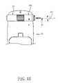
- FIG. 1is a perspective view of a portable communication device according to a preferred embodiment of the present invention
- FIG. 2is a front view of the portable communication device shown in FIG. 1 ;
- FIG. 3is a side view of the portable communication device shown in FIG. 1 ;
- FIG. 4is a bottom view of the portable communication device shown in FIG. 1 ;
- FIG. 5Ais a rear view of the portable communication device of the preferred embodiment of the present invention with a camera lens module of the portable communication device withdrawn out from a main body of the portable communication device;
- FIG. 5Bis a rear view of the portable communication device of the preferred embodiment of the present invention showing the camera lens module of the portable communication device inserted into the main body of the portable communication device;
- FIG. 6is an exploded perspective view of an inserting/drawing unit of the camera lens module of a portable communication device according to another preferred embodiment of the present invention.
- FIG. 7is a perspective view in partial cut-away illustrating a housing and a stopper cam of the inserting/drawing unit of the camera lens module of the portable communication device according to the preferred embodiment of the present invention
- FIG. 8is a perspective view of the inserting/drawing unit of the camera lens module of the portable communication device according to the preferred embodiment of the present invention illustrating the camera lens module inserted into the stopper cam;
- FIG. 9is a side view of the inserting/drawing unit of the camera lens module of the portable communication device according to the preferred embodiment of the present invention illustrating latching protrusions of a rotary cam contacting first guide inclined surfaces of the stopper cam;
- FIG. 10is a perspective view of the inserting/drawing unit of the camera lens module of the portable communication device according to the preferred embodiment of the present invention illustrating the operation of the stopper cam;
- FIG. 11is a side view of the inserting/drawing unit of the camera lens module of the portable communication device according to the preferred embodiment of the present invention illustrating the latch protrusions of the rotary cam guided by second guide inclined surfaces of the stopper cam;
- FIG. 12is a perspective view of the inserting/drawing unit of the camera lens module of the portable communication device according to the preferred embodiment of the present invention illustrating the latching protrusions of the rotary cam guided into first guide grooves of the stopper cam;
- FIG. 13is a side view of the inserting/drawing unit of the camera lens module of the portable communication device according to the preferred embodiment of the present invention illustrating the latching protrusions of the rotary cam guided into the first guide grooves of the stopper cam;
- FIG. 14is a perspective view of the inserting/drawing unit of the camera lens module of the portable communication device according to the preferred embodiment of the present invention illustrating the latching protrusions of the rotary cam guided into the first guide grooves of the stopper cam and guide protrusions of a lens housing guided into second guide grooves of the stopper cam;
- FIG. 15is a side view of the inserting/drawing unit of the camera lens module of the portable communication device according to the preferred embodiment of the present invention illustrating the latching protrusions of the rotary cam guided into the first guide grooves of the stopper cam and the guide protrusions of the lens housing guided into the second guide grooves of the stopper cam;
- FIG. 16is a rear view illustrating the inserting/drawing unit of the camera lens module according to the preferred embodiment of the present invention inserted into the main body of the portable communication device;
- FIG. 17is a cross-sectional view taken along the line A–A′ of FIG. 16 ;
- FIG. 18is a rear view showing the inserting/drawing unit of the camera lens module according to the preferred embodiment of the present invention drawn out from the main body of the portable communication device;
- FIG. 19is a cross-sectional view taken along the line B–B′ of FIG. 18 ;
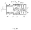
- FIG. 20is a cross-sectional view of the inserting/drawing unit of the camera lens module of the portable communication device according to the preferred embodiment of the present invention illustrating the operation of the camera lens module while the inserting/drawing unit of the camera lens module is drawn out from the main body of the portable communication device.
- a portable communication deviceincludes a first housing 10 extending in a first direction ⁇ circle around ( 1 ) ⁇ , and a second housing 20 extending in a second direction ⁇ circle around ( 2 ) ⁇ , which is perpendicular to the first direction ⁇ circle around ( 1 ) ⁇ .
- the second housing 20is formed at a bottom surface 10 c of the first housing 10 .
- a portion of an outer circumferential surface of the second housing 20protrudes outward from the bottom surface 10 c of the first housing 10 .
- the first direction ⁇ circle around ( 1 ) ⁇is a longitudinal direction along which the first housing 10 extends
- the second direction ⁇ circle around ( 2 ) ⁇is a direction perpendicular to the first direction ⁇ circle around ( 1 ) ⁇ .
- the camera lens module 30is rotated about the second direction ⁇ circle around ( 2 ) ⁇ .
- the camera lens module 30is linearly moved along the second direction ⁇ circle around ( 2 ) ⁇ .
- the first housing 10is formed in the shape of a bar or a plate.
- the first housing 10includes a top surface 10 a , the bottom surface 10 c , and a pair of side surfaces 10 b .
- On the top surface 10 a of the first housing 10are arranged a speaker unit 102 , a display unit 104 , a plurality of keys 106 and a microphone unit 108 .
- the second housing 20is preferably formed in the shape of a cylinder. A portion of the second housing 20 protrudes at a region of the bottom surface 10 c of the first housing 10 .
- the second housing 20is disposed in the shape of a protruded jaw in the vicinity of the upper part of the bottom surface 10 c of the first housing 10 . Also, the second housing 20 extends between the side surfaces 10 b of the first housing 10 in the second direction ⁇ circle around ( 2 ) ⁇ .
- the camera lens module 30is formed in the shape of a cylinder, and the camera lens module 30 is inserted into or drawn out from the second housing 20 at one side of the second housing 20 .
- the camera lens module 30is mounted at one side of the second housing 20 in a pop-up fashion.
- the camera lens module 30is drawn out from the second housing 20 , it is inserted into the second housing 20 , using a force by a user of the portable communication device.
- the camera lens module 30is inserted in the second housing 20 , it is drawn out from the second housing, using a force by a user of the portable communication device.
- the camera lens module 30is inserted into or drawn out from the second housing 20 by pushing the camera lens module 30 .
- the camera lens module 30can be inserted into or drawn out from the second housing 20 by rotating the camera lens module 30 .
- the camera lens module 30can be automatically inserted into or drawn out from the second housing 20 using an additional operating button (not shown).
- the camera lens module 30has a camera lens 302 mounted at a preferred region of the outer circumferential surface 301 thereof.
- the camera lens 302is also drawn out from the second housing 20 .
- the camera lens module 30can be rotated and linearly moved.
- the camera lens module 30can be rotated about the second direction ⁇ circle around ( 2 ) ⁇ , and linearly moved in the second direction ⁇ circle around ( 2 ) ⁇ .
- the camera lens 302is turned toward a subject by rotating the camera lens module 30 .
- the camera lens module 30is inserted into the second housing 20 by linearly moving the camera lens module 30 when it is not in use.
- the camera lens module 30is drawn out from the second housing 20 by linearly moving the camera lens module 30 when it is to be used.
- the second housing 20is further provided at a middle part thereof with a lamp.
- the inserting/drawing unit 100 of the camera lens module 300 of the portable communication deviceis provided at the second housing 20 .
- a camera lens module 300which includes a cylindrical lens housing 301 for accommodating a camera lens unit 45 therein, as shown in FIG. 6 .
- a lens opening 301 bAt an outer circumferential surface of the lens housing 301 of the camera lens module 300 is formed a lens opening 301 b through which a picture of an outer subject is taken.
- the lens housing 301 of the camera lens module 300has an open end 302 through the camera lens unit 45 is inserted into the lens housing 301 .
- the lens housing 301 of the cameral lens module 300is provided at the other end opposite to the open end 302 with a plurality of saw-toothed portions 303 having inclined surfaces formed along the circumference of the lens housing 301 .
- engagement grooves 304Inside the saw-toothed portions 303 are formed engagement grooves 304 , in which engaging parts 401 formed at a rotary cam 400 are engaged. Consequently, the engaging parts 401 of the rotary cam 400 are engaged in the corresponding engagement grooves 304 .
- the rotary cam 400extends in the longitudinal direction of the lens housing 301 .
- a connection protrusion 306which extends in the longitudinal direction of the lens housing 301 .
- a shaft 900having a coupling part 901 formed at one end thereof (shown in FIG. 17 ).
- a screw hole 306 aIn the connection protrusion 306 is formed a screw hole 306 a , through which a screw 1000 is inserted so that the connection protrusion 306 is connected with the shaft 900 .
- a bush ring 600having a rib 601 through which the coupling part 901 of the shaft 900 is inserted.
- a second spring 702which is arranged on the shaft 900 .
- the second spring 702provides an elastic force, by which the inclined surfaces of the saw-toothed portions 303 of the camera lens module 300 are separated from inclined surfaces 403 a formed at the latching protrusions 403 of the rotary cam 400 .
- the camera lens module 300is drawn out from the housing 200 while being rotated about a hinge axis A 1 (shown in FIG. 8 ) of the camera lens module 300 .
- On the coupling portion 901 of the shaft 900is fitted an O-ring 800 , and the rotary cam 400 is rotatably attached to the lens housing 301 .
- the lens housing 310 and the rotary cam 400are mounted in the housing 200 .
- a deco part 201attached to the camera lens module 300 using at least one screw 1000 . Consequently, the deco part 201 is inserted into or drawn out from the housing 200 with the camera lens module 300 .
- the deco part 201has at least one screw hole 201 a formed at a region thereof, through which the screw 1000 is inserted.
- the screw 1000is inserted into at least one screw-fixing hole 305 formed in the lens housing 301 of the camera lens module 300 through the screw hole 201 a , and thus the deco part 201 is attached to the lens housing 301 .
- a deco cap 201 bAt the outer surface of the deco part 210 is provided a deco cap 201 b for protecting the deco part 201 .
- the deco cap 201has at least one insertion groove 201 c in which the head of the screw 1000 is placed when the screw 100 is inserted through the screw hole 201 a of the deco part 201 .
- a spring cap 202for supporting a first spring 701 , which is provided between the spring cap 202 and the rotary cam 400 for providing an elastic force, by which the camera lens module 300 is inserted into or drawn out from the housing 200 .
- On the outer circumferential surface of the spring cap 202are formed a plurality of engagement portions 202 a each having a protrusion 202 b formed at one end thereof.
- the protrusions 202 b of the engagement portions 202 aare engaged in engagement grooves 203 formed at the housing 200 . Consequently, the spring cap 202 is attached to the housing 200 by the engagement of the engagement portions 202 a in the engagement grooves 203 of the housing 200 .
- a spring fixing protrusion 202 cfor fixing and supporting the first spring 701 .
- a bush ring fixing protrusion 602is formed at the central part of the bush ring 600 . Consequently, the second spring 702 is disposed between the camera lens module 300 and the bush ring 600 , and the second spring 702 is fixed to the connection protrusion 306 of the camera lens module 300 and to the bush ring fixing protrusion 602 .
- a stopper cam 500which releasably restricts the rotation of the rotary cam 400 .
- the camera lens module 300can be inserted into or drawn out from the housing 200 as the camera lens module 300 and the rotary cam 400 are rotated together with each other when the camera lens module 300 is pushed, as illustrated in FIG. 7 .
- the stopper cam 500is supported by a latching jaw 204 formed inside the housing 202 .
- the camera lens module 300When the camera lens module 300 is pushed as illustrated in FIGS. 8 and 9 , the camera lens module 300 is drawn out from the housing 200 in the direction in which the camera lens module 300 is pushed.
- the latching protrusions 403 of the rotary cam 400are separated from latching jaws 501 a of first guide inclined surfaces 501 of the stopper cam 500 , as shown in FIGS. 10 and 11 .
- the rotary cam 400is rotated in a direction of rotation ⁇ circle around ( 3 ) ⁇ , and the latching protrusions 403 of the rotary cam 400 are moved to second guide inclined surfaces 502 of the stopper cam 500 while being rotated.
- first guide grooves 503which are formed in the longitudinal direction of the stopper cam 500 for guiding the latching protrusions 403 of the rotary cam 400 . Consequently, the latching protrusions 403 of the rotary cam 400 are guided using the second guide inclined surfaces 502 and moved into the first guide grooves 503 while being rotated. The latching protrusions 403 of the rotary cam 400 are inserted into the first guide grooves 503 as illustrated in FIGS. 13 and 14 .
- the lens housing 301is drawn out from the housing 200 in the direction in which the lens housing 301 is pushed using the elastic force of the first spring 701 .
- second guide grooves 504which are formed in the longitudinal direction of the stopper cam 500 .
- the rotary cam 400has an undercut part 402 for restricting the drawing operation of the rotary cam 400 when the lens housing 301 and the rotary cam 400 are drawn out from the housing 200 , as shown in FIG. 15 . Consequently, the drawing operation of the stopper cam 500 is stopped when the stopper cam 500 contacts the undercut part 402 of the rotary cam 400 .
- the engaging parts 401 of the rotary cam 400are disengaged from the engagement grooves 304 of the lens housing 301 using the elastic force of the second spring 702 , as illustrated in FIGS. 19 and 20 . Consequently, the lens housing 301 can be rotated about the hinge axis A 1 of the camera lens module 300 , as illustrated in FIG. 18 . Under this condition, a picture of a subject can be taken using the camera lens unit 45 of the camera lens module 300 .
- the engaging parts 401 of the rotary cam 400are engaged into the engagement grooves 304 of the lens housing 301 .
- the lens housing 301 and the rotary cam 400are inserted into the housing 200 .
- the guide protrusions 301 a of the lens housing 301are guided into the second guide grooves 504 of the stopper cam 500 .
- the latching protrusions 403 of the rotary cam 400are separated from the first guide grooves 503 of the stopper cam 500 .
- the latching protrusions 403 of the rotary cam 400are moved to the first guide inclined surfaces 501 of the stopper cam 500 as the rotary cam 400 is moved in the direction ⁇ circle around ( 3 ) ⁇ while being rotated.
- the latching protrusions 403 of the rotary cam 400are guided to the latching jaws 501 a of first guide inclined surfaces 501 of the stopper cam 500 along the first guide inclined surfaces 501 of the stopper cam 500 .
- the latching protrusions 403 of the rotary cam 400contact the latching jaws 501 a , and the lens housing 301 remains inserted in the stopper cam 500 .
Landscapes
- Engineering & Computer Science (AREA)
- Multimedia (AREA)
- Signal Processing (AREA)
- Studio Devices (AREA)
- Telephone Set Structure (AREA)
Abstract
Description
Claims (24)
Applications Claiming Priority (4)
| Application Number | Priority Date | Filing Date | Title |
|---|---|---|---|
| KR36391/2003 | 2003-06-05 | ||
| KR20030036391 | 2003-06-05 | ||
| KR1020030061236AKR20040105531A (en) | 2003-06-05 | 2003-09-02 | Portable communication device |
| KR61236/2003 | 2003-09-02 |
Publications (2)
| Publication Number | Publication Date |
|---|---|
| US20040245342A1 US20040245342A1 (en) | 2004-12-09 |
| US7210629B2true US7210629B2 (en) | 2007-05-01 |
Family
ID=33161629
Family Applications (1)
| Application Number | Title | Priority Date | Filing Date |
|---|---|---|---|
| US10/851,804Expired - Fee RelatedUS7210629B2 (en) | 2003-06-05 | 2004-05-21 | Portable communication device |
Country Status (3)
| Country | Link |
|---|---|
| US (1) | US7210629B2 (en) |
| EP (1) | EP1484920B1 (en) |
| CN (1) | CN1574858A (en) |
Cited By (36)
| Publication number | Priority date | Publication date | Assignee | Title |
|---|---|---|---|---|
| US20040218092A1 (en)* | 2003-04-30 | 2004-11-04 | Lg Electronics Inc. | Camera assembly for a mobile communication device |
| US20060029379A1 (en)* | 2004-08-05 | 2006-02-09 | Butterworth Mark M | Use of telephone-specific components to provide refocusing in a camera-ready device |
| US20060084465A1 (en)* | 2004-10-04 | 2006-04-20 | Lg Electronics Inc | Mobile communication terminal |
| US20060275031A1 (en)* | 2005-06-03 | 2006-12-07 | Asustek Computer Inc. | Revolving lens module for mobile communication devices |
| USD560199S1 (en)* | 2007-02-02 | 2008-01-22 | Samsung Electronics Co., Ltd. | Portable telephone |
| USD560644S1 (en)* | 2007-03-08 | 2008-01-29 | Samsung Electronics Co., Ltd. | Portable telephone |
| USD562291S1 (en)* | 2007-02-15 | 2008-02-19 | Samsung Electronics Co., Ltd. | Cellular phone |
| USD562290S1 (en)* | 2006-12-08 | 2008-02-19 | Samsung Electronics Co., Ltd. | Mobile phone |
| USD562294S1 (en)* | 2007-02-23 | 2008-02-19 | Samsung Electronics Co., Ltd. | Cellular phone |
| USD562293S1 (en)* | 2007-02-23 | 2008-02-19 | Samsung Electronics Co., Ltd. | Cellular phone |
| USD562793S1 (en)* | 2006-12-08 | 2008-02-26 | Samsung Electronics Co., Ltd. | Mobile phone |
| USD563370S1 (en)* | 2006-10-31 | 2008-03-04 | Samsung Electronics Co., Ltd. | Portable phone |
| USD563937S1 (en)* | 2006-12-20 | 2008-03-11 | Samsung Electronics Co., Ltd. | Portable phone |
| USD565016S1 (en)* | 2006-12-20 | 2008-03-25 | Samsung Electronics Co., Ltd. | Portable phone |
| USD567205S1 (en)* | 2006-02-10 | 2008-04-22 | Samsung Electronics Co., Ltd. | Portable phone with removable wireless earpiece |
| USD567781S1 (en)* | 2005-09-23 | 2008-04-29 | Lg Electronics Inc. | Mobile phone |
| USD567794S1 (en)* | 2006-12-29 | 2008-04-29 | Samsung Electronics Co., Ltd. | Portable phone |
| USD567785S1 (en)* | 2006-02-10 | 2008-04-29 | Samsung Electronics Co., Ltd. | Portable phone |
| USD569363S1 (en)* | 2006-11-20 | 2008-05-20 | Samsung Electronics Co., Ltd. | Portable telephone |
| USD569836S1 (en)* | 2007-06-21 | 2008-05-27 | Samsung Electronics Co., Ltd. | Portable telephone |
| USD573129S1 (en)* | 2007-09-27 | 2008-07-15 | Samsung Electronics Co., Ltd. | Cellular phone |
| USD573965S1 (en)* | 2006-10-31 | 2008-07-29 | Samsung Electronics Co., Ltd. | Portable phone |
| US20080194290A1 (en)* | 2005-03-30 | 2008-08-14 | Koninklijke Philips Electronics , N.V. | Portable Electronic Device Having A Rotary Camera Unit |
| USD575753S1 (en)* | 2005-12-16 | 2008-08-26 | Samsung Electronics Co., Ltd. | Portable phone |
| USD585412S1 (en)* | 2008-02-12 | 2009-01-27 | Samsung Electronics Co., Ltd. | Cellular phone |
| USD586770S1 (en)* | 2006-11-20 | 2009-02-17 | Samsung Electronics Co., Ltd. | Portable telephone |
| USD587230S1 (en)* | 2006-11-20 | 2009-02-24 | Samsung Electronics Co., Ltd. | Portable telephone |
| USD587229S1 (en)* | 2006-11-20 | 2009-02-24 | Samsung Electronics Co., Ltd. | Portable telephone |
| US20090051776A1 (en)* | 2007-08-21 | 2009-02-26 | Mats Goran Henry Wernersson | Autofocus assembly |
| USD593980S1 (en)* | 2007-12-26 | 2009-06-09 | Samsung Electronics Co., Ltd. | Portable telephone |
| USD596152S1 (en)* | 2007-12-28 | 2009-07-14 | Samsung Electronics Co., Ltd. | Portable telephone |
| US20090209305A1 (en)* | 2005-08-18 | 2009-08-20 | Sang Ho Lee | Personal portable device |
| USD635948S1 (en)* | 2010-03-05 | 2011-04-12 | Lg Electronics Inc. | Mobile phone |
| USD654036S1 (en)* | 2010-02-04 | 2012-02-14 | Nokia Corporation | Handset |
| US20170244903A1 (en)* | 2016-02-21 | 2017-08-24 | Jinrong Yang | Portable electronic device with retractable antenna rod for a camera |
| US20210286380A1 (en)* | 2018-11-30 | 2021-09-16 | Guangdong Oppo Mobile Telecommunications Corp., Ltd. | Method and Apparatus for Calibrating Sliding of Sliding Component |
Families Citing this family (26)
| Publication number | Priority date | Publication date | Assignee | Title |
|---|---|---|---|---|
| JP3972795B2 (en)* | 2002-10-31 | 2007-09-05 | 松下電器産業株式会社 | Switchgear |
| KR100739564B1 (en)* | 2003-07-31 | 2007-07-16 | 엘지전자 주식회사 | Mobile terminal with camera |
| US20060291853A1 (en)* | 2005-06-24 | 2006-12-28 | Asustek Computer Inc. | Electronic device and image capture module thereof |
| US7435018B2 (en)* | 2006-06-28 | 2008-10-14 | Inventec Corporation | Hidden image capturing device |
| US7878937B2 (en)* | 2007-06-11 | 2011-02-01 | Ford Global Technologies, Llc | Dual-pilot axle assembly for an automotive vehicle driveline |
| USD580904S1 (en)* | 2007-07-18 | 2008-11-18 | Samsung Electronics Co., Ltd. | Portable phone |
| USD590366S1 (en)* | 2007-07-27 | 2009-04-14 | Pantech & Curitel Communications, Inc. | Mobile communication terminal |
| USD581382S1 (en)* | 2007-08-27 | 2008-11-25 | Samsung Electronics Co., Ltd. | Mobile phone |
| USD590794S1 (en)* | 2007-08-27 | 2009-04-21 | Samsung Electronics Co., Ltd. | Mobile phone |
| USD589018S1 (en)* | 2007-12-10 | 2009-03-24 | Samsung Electronics Co., Ltd. | Mobile phone |
| TWD136569S1 (en)* | 2008-10-15 | 2010-08-21 | 宏達國際電子股份有限公司 | Mobile phone |
| WO2011149381A1 (en)* | 2010-05-24 | 2011-12-01 | Mikheyev Alexander Alexandrovich | Photo-video camera on a mobile telephone (variants) |
| TW201409203A (en)* | 2012-08-29 | 2014-03-01 | Hon Hai Prec Ind Co Ltd | Electronic device having camera module |
| TW201410013A (en)* | 2012-08-29 | 2014-03-01 | Hon Hai Prec Ind Co Ltd | Electronic device having camera module |
| KR102055204B1 (en)* | 2013-09-09 | 2019-12-12 | 엘지전자 주식회사 | Display device including camera module |
| US20150288880A1 (en)* | 2014-04-07 | 2015-10-08 | Wu-Hsiung Chen | Image capturing method and image capturing apparatus |
| CN104796507B (en)* | 2015-04-29 | 2018-09-11 | 天津德铃通信部品有限公司 | Can 360 ° rotation and stop bit camera bracket and mobile terminal |
| CN105842959B (en)* | 2016-05-13 | 2018-08-07 | 北京小米移动软件有限公司 | a retractable camera |
| CN107197133B (en) | 2017-07-21 | 2019-11-29 | 维沃移动通信有限公司 | A kind of mobile terminal and CCD camera assembly |
| CN110166666B (en)* | 2018-02-13 | 2020-06-02 | Oppo广东移动通信有限公司 | Electronic equipment and control method of camera module |
| CN110196616B (en)* | 2018-02-26 | 2020-12-11 | Oppo广东移动通信有限公司 | Control method, electronic device and readable storage medium of a functional module |
| CN110460697B (en)* | 2018-05-07 | 2021-07-13 | Oppo广东移动通信有限公司 | Electronic equipment |
| CN109788683B (en)* | 2019-01-31 | 2020-09-29 | 维沃移动通信有限公司 | Electronic device |
| CN110049213B (en)* | 2019-04-11 | 2021-05-07 | 华为技术有限公司 | Light guide module and terminal equipment |
| CN111885225A (en)* | 2020-06-28 | 2020-11-03 | 维沃移动通信有限公司 | an electronic device |
| CN115507264B (en)* | 2022-09-30 | 2025-02-21 | 联想(北京)有限公司 | Electronic equipment |
Citations (19)
| Publication number | Priority date | Publication date | Assignee | Title |
|---|---|---|---|---|
| US4998318A (en)* | 1989-03-10 | 1991-03-12 | Pioneer Electronic Corporation | Knob device |
| US5612732A (en)* | 1993-03-31 | 1997-03-18 | Casio Computer Co., Ltd. | Portable compact imaging and displaying apparatus with rotatable camera |
| JPH1075287A (en) | 1996-08-30 | 1998-03-17 | Kokusai Electric Co Ltd | Mobile video phone |
| US5815759A (en)* | 1998-03-19 | 1998-09-29 | Umax Data System | Extended adjusting mechanism for the lens set of an imaging system |
| US5920061A (en)* | 1997-05-29 | 1999-07-06 | Metanetics Corporation | Portable data collection device including imaging assembly with modular high density dataform reader assembly |
| US6266090B1 (en)* | 1998-01-02 | 2001-07-24 | Umax Data Systems Inc. | Device for controlling a rotation of a lens in a digital camera |
| US6285833B1 (en)* | 1998-11-13 | 2001-09-04 | Fuji Photo Optical Co., Ltd. | Camera |
| US20010036845A1 (en)* | 2000-01-10 | 2001-11-01 | Jun-Sang Park | Radiotelephone for visual communication |
| US20020001467A1 (en)* | 1997-05-01 | 2002-01-03 | Yoshiharu Tanaka | Driving mechanism using shape-memory alloy |
| US6370362B1 (en)* | 1998-02-27 | 2002-04-09 | Nokia Mobile Phones Limited | Slide cover for a communication unit |
| US6389233B2 (en)* | 2000-01-05 | 2002-05-14 | Fuji Photo Film Co., Ltd. | Cam mechanism for device having pop-up part |
| WO2002076067A1 (en) | 2001-03-19 | 2002-09-26 | Matsushita Electric Industrial Co., Ltd. | Mobile terminal device having camera function |
| US20040204126A1 (en)* | 2002-05-24 | 2004-10-14 | Rene Reyes | Wireless mobile device |
| US6812958B1 (en)* | 1998-09-10 | 2004-11-02 | Intel Corporation | Storable digital camera associated with a computer system |
| US20040242289A1 (en)* | 2003-06-02 | 2004-12-02 | Roger Jellicoe | Configuration driven automatic antenna impedance matching |
| US6832729B1 (en)* | 2001-03-23 | 2004-12-21 | Zih Corp. | Portable data collection device for reading fluorescent indicia |
| US6832717B1 (en)* | 1999-05-25 | 2004-12-21 | Silverbrook Research Pty Ltd | Computer system interface surface |
| US6832724B2 (en)* | 1993-03-26 | 2004-12-21 | Symbol Technologies, Inc. | Electro-optical assembly for image projection, especially in portable instruments |
| US6876379B1 (en)* | 1999-11-24 | 2005-04-05 | Orange Personal Communications Services Limited | Mobile communications |
- 2004
- 2004-05-21USUS10/851,804patent/US7210629B2/ennot_activeExpired - Fee Related
- 2004-05-25EPEP04012373Apatent/EP1484920B1/ennot_activeExpired - Lifetime
- 2004-05-28CNCNA200410047248XApatent/CN1574858A/enactivePending
Patent Citations (19)
| Publication number | Priority date | Publication date | Assignee | Title |
|---|---|---|---|---|
| US4998318A (en)* | 1989-03-10 | 1991-03-12 | Pioneer Electronic Corporation | Knob device |
| US6832724B2 (en)* | 1993-03-26 | 2004-12-21 | Symbol Technologies, Inc. | Electro-optical assembly for image projection, especially in portable instruments |
| US5612732A (en)* | 1993-03-31 | 1997-03-18 | Casio Computer Co., Ltd. | Portable compact imaging and displaying apparatus with rotatable camera |
| JPH1075287A (en) | 1996-08-30 | 1998-03-17 | Kokusai Electric Co Ltd | Mobile video phone |
| US20020001467A1 (en)* | 1997-05-01 | 2002-01-03 | Yoshiharu Tanaka | Driving mechanism using shape-memory alloy |
| US5920061A (en)* | 1997-05-29 | 1999-07-06 | Metanetics Corporation | Portable data collection device including imaging assembly with modular high density dataform reader assembly |
| US6266090B1 (en)* | 1998-01-02 | 2001-07-24 | Umax Data Systems Inc. | Device for controlling a rotation of a lens in a digital camera |
| US6370362B1 (en)* | 1998-02-27 | 2002-04-09 | Nokia Mobile Phones Limited | Slide cover for a communication unit |
| US5815759A (en)* | 1998-03-19 | 1998-09-29 | Umax Data System | Extended adjusting mechanism for the lens set of an imaging system |
| US6812958B1 (en)* | 1998-09-10 | 2004-11-02 | Intel Corporation | Storable digital camera associated with a computer system |
| US6285833B1 (en)* | 1998-11-13 | 2001-09-04 | Fuji Photo Optical Co., Ltd. | Camera |
| US6832717B1 (en)* | 1999-05-25 | 2004-12-21 | Silverbrook Research Pty Ltd | Computer system interface surface |
| US6876379B1 (en)* | 1999-11-24 | 2005-04-05 | Orange Personal Communications Services Limited | Mobile communications |
| US6389233B2 (en)* | 2000-01-05 | 2002-05-14 | Fuji Photo Film Co., Ltd. | Cam mechanism for device having pop-up part |
| US20010036845A1 (en)* | 2000-01-10 | 2001-11-01 | Jun-Sang Park | Radiotelephone for visual communication |
| WO2002076067A1 (en) | 2001-03-19 | 2002-09-26 | Matsushita Electric Industrial Co., Ltd. | Mobile terminal device having camera function |
| US6832729B1 (en)* | 2001-03-23 | 2004-12-21 | Zih Corp. | Portable data collection device for reading fluorescent indicia |
| US20040204126A1 (en)* | 2002-05-24 | 2004-10-14 | Rene Reyes | Wireless mobile device |
| US20040242289A1 (en)* | 2003-06-02 | 2004-12-02 | Roger Jellicoe | Configuration driven automatic antenna impedance matching |
Cited By (42)
| Publication number | Priority date | Publication date | Assignee | Title |
|---|---|---|---|---|
| US20040218092A1 (en)* | 2003-04-30 | 2004-11-04 | Lg Electronics Inc. | Camera assembly for a mobile communication device |
| US7847860B2 (en)* | 2003-04-30 | 2010-12-07 | Lg Electronics, Inc. | Camera assembly for a mobile communication device |
| US20060029379A1 (en)* | 2004-08-05 | 2006-02-09 | Butterworth Mark M | Use of telephone-specific components to provide refocusing in a camera-ready device |
| US7468753B2 (en)* | 2004-08-05 | 2008-12-23 | Aptina Imaging Corporation | Use of telephone-specific components to provide refocusing in a camera-ready device |
| US20060084465A1 (en)* | 2004-10-04 | 2006-04-20 | Lg Electronics Inc | Mobile communication terminal |
| US7689244B2 (en)* | 2004-10-04 | 2010-03-30 | Lg Electronics Inc. | Mobile communication terminal |
| US20080194290A1 (en)* | 2005-03-30 | 2008-08-14 | Koninklijke Philips Electronics , N.V. | Portable Electronic Device Having A Rotary Camera Unit |
| US20060275031A1 (en)* | 2005-06-03 | 2006-12-07 | Asustek Computer Inc. | Revolving lens module for mobile communication devices |
| US20090209305A1 (en)* | 2005-08-18 | 2009-08-20 | Sang Ho Lee | Personal portable device |
| USD567781S1 (en)* | 2005-09-23 | 2008-04-29 | Lg Electronics Inc. | Mobile phone |
| USD575753S1 (en)* | 2005-12-16 | 2008-08-26 | Samsung Electronics Co., Ltd. | Portable phone |
| USD567785S1 (en)* | 2006-02-10 | 2008-04-29 | Samsung Electronics Co., Ltd. | Portable phone |
| USD567205S1 (en)* | 2006-02-10 | 2008-04-22 | Samsung Electronics Co., Ltd. | Portable phone with removable wireless earpiece |
| USD573965S1 (en)* | 2006-10-31 | 2008-07-29 | Samsung Electronics Co., Ltd. | Portable phone |
| USD563370S1 (en)* | 2006-10-31 | 2008-03-04 | Samsung Electronics Co., Ltd. | Portable phone |
| USD587229S1 (en)* | 2006-11-20 | 2009-02-24 | Samsung Electronics Co., Ltd. | Portable telephone |
| USD569363S1 (en)* | 2006-11-20 | 2008-05-20 | Samsung Electronics Co., Ltd. | Portable telephone |
| USD586770S1 (en)* | 2006-11-20 | 2009-02-17 | Samsung Electronics Co., Ltd. | Portable telephone |
| USD587230S1 (en)* | 2006-11-20 | 2009-02-24 | Samsung Electronics Co., Ltd. | Portable telephone |
| USD562793S1 (en)* | 2006-12-08 | 2008-02-26 | Samsung Electronics Co., Ltd. | Mobile phone |
| USD562290S1 (en)* | 2006-12-08 | 2008-02-19 | Samsung Electronics Co., Ltd. | Mobile phone |
| USD565016S1 (en)* | 2006-12-20 | 2008-03-25 | Samsung Electronics Co., Ltd. | Portable phone |
| USD563937S1 (en)* | 2006-12-20 | 2008-03-11 | Samsung Electronics Co., Ltd. | Portable phone |
| USD567794S1 (en)* | 2006-12-29 | 2008-04-29 | Samsung Electronics Co., Ltd. | Portable phone |
| USD560199S1 (en)* | 2007-02-02 | 2008-01-22 | Samsung Electronics Co., Ltd. | Portable telephone |
| USD562291S1 (en)* | 2007-02-15 | 2008-02-19 | Samsung Electronics Co., Ltd. | Cellular phone |
| USD562293S1 (en)* | 2007-02-23 | 2008-02-19 | Samsung Electronics Co., Ltd. | Cellular phone |
| USD562294S1 (en)* | 2007-02-23 | 2008-02-19 | Samsung Electronics Co., Ltd. | Cellular phone |
| USD560644S1 (en)* | 2007-03-08 | 2008-01-29 | Samsung Electronics Co., Ltd. | Portable telephone |
| USD569836S1 (en)* | 2007-06-21 | 2008-05-27 | Samsung Electronics Co., Ltd. | Portable telephone |
| US20090051776A1 (en)* | 2007-08-21 | 2009-02-26 | Mats Goran Henry Wernersson | Autofocus assembly |
| US7656460B2 (en)* | 2007-08-21 | 2010-02-02 | Sony Ericsson Mobile Communications Ab | Autofocus assembly that adjusts a lens in the optical axis direction by alignment of holes in a spacing ring that receive ball bearings |
| USD573129S1 (en)* | 2007-09-27 | 2008-07-15 | Samsung Electronics Co., Ltd. | Cellular phone |
| USD593980S1 (en)* | 2007-12-26 | 2009-06-09 | Samsung Electronics Co., Ltd. | Portable telephone |
| USD596152S1 (en)* | 2007-12-28 | 2009-07-14 | Samsung Electronics Co., Ltd. | Portable telephone |
| USD585412S1 (en)* | 2008-02-12 | 2009-01-27 | Samsung Electronics Co., Ltd. | Cellular phone |
| USD654036S1 (en)* | 2010-02-04 | 2012-02-14 | Nokia Corporation | Handset |
| USD635948S1 (en)* | 2010-03-05 | 2011-04-12 | Lg Electronics Inc. | Mobile phone |
| US20170244903A1 (en)* | 2016-02-21 | 2017-08-24 | Jinrong Yang | Portable electronic device with retractable antenna rod for a camera |
| US10659697B2 (en)* | 2016-02-21 | 2020-05-19 | Jinrong Yang | Portable electronic device with retractable antenna rod for a camera |
| US20210286380A1 (en)* | 2018-11-30 | 2021-09-16 | Guangdong Oppo Mobile Telecommunications Corp., Ltd. | Method and Apparatus for Calibrating Sliding of Sliding Component |
| US11789470B2 (en)* | 2018-11-30 | 2023-10-17 | Guangdong Oppo Mobile Telecommunications Corp., Ltd. | Method and apparatus for calibrating sliding of sliding component |
Also Published As
| Publication number | Publication date |
|---|---|
| US20040245342A1 (en) | 2004-12-09 |
| EP1484920B1 (en) | 2008-12-03 |
| CN1574858A (en) | 2005-02-02 |
| EP1484920A1 (en) | 2004-12-08 |
Similar Documents
| Publication | Publication Date | Title |
|---|---|---|
| US7210629B2 (en) | Portable communication device | |
| US7496194B2 (en) | Sliding and swing apparatus for a portable apparatus | |
| US8032192B2 (en) | Portable terminal and sliding/swing-type cradling apparatus thereof | |
| KR100630139B1 (en) | Portable terminal having a biaxial hinge device | |
| KR100790088B1 (en) | Sliding swing device of mobile terminal | |
| US7885693B2 (en) | Sliding device for dual sliding-type portable communication apparatus | |
| US20050020327A1 (en) | Speaker-up type portable terminal | |
| US7440783B2 (en) | Dual axis hinge apparatus for portable terminal | |
| US20050245297A1 (en) | Portable communication device with sliding and pop-up type keypads | |
| US20050054397A1 (en) | Portable sliding-type digital communication device and locking apparatus thereof | |
| KR100842626B1 (en) | Locking device for sliding swing type mobile terminal | |
| KR100493102B1 (en) | Hinge device for portable terminal with sub housing stopper | |
| US7302283B2 (en) | Portable digital communication apparatus having improved grip | |
| KR100526555B1 (en) | Portable wireless terminal | |
| US20050287853A1 (en) | Interface connector cover opening and closing apparatus for mobile communications terminals | |
| US7369178B2 (en) | Camera lens assembly for a portable terminal | |
| US20060135227A1 (en) | Sliding/folding combination type portable digital communication apparatus and hinge unit thereof | |
| US20070010301A1 (en) | Portable terminal with slide keypad for convenient data input | |
| KR100600702B1 (en) | Rotating module for display device | |
| US20060132851A1 (en) | Slide type portable device having an optical zoom assembly | |
| KR200345710Y1 (en) | rotation module of display device | |
| KR200306381Y1 (en) | Hinge module for portable radiotelephone | |
| KR20040105531A (en) | Portable communication device | |
| KR20070040091A (en) | Locking device for sliding swing device for mobile terminal |
Legal Events
| Date | Code | Title | Description |
|---|---|---|---|
| AS | Assignment | Owner name:SAMSUNG ELECTRONICS CO., LTD., KOREA, REPUBLIC OF Free format text:ASSIGNMENT OF ASSIGNORS INTEREST;ASSIGNORS:CHO, JIN-HEE;KIM, BYUNG-SIK;PARK, SEUNG-MIN;AND OTHERS;REEL/FRAME:015383/0277 Effective date:20040430 | |
| STCF | Information on status: patent grant | Free format text:PATENTED CASE | |
| FEPP | Fee payment procedure | Free format text:PAYOR NUMBER ASSIGNED (ORIGINAL EVENT CODE: ASPN); ENTITY STATUS OF PATENT OWNER: LARGE ENTITY | |
| FPAY | Fee payment | Year of fee payment:4 | |
| FPAY | Fee payment | Year of fee payment:8 | |
| FEPP | Fee payment procedure | Free format text:PAYOR NUMBER ASSIGNED (ORIGINAL EVENT CODE: ASPN); ENTITY STATUS OF PATENT OWNER: LARGE ENTITY Free format text:PAYER NUMBER DE-ASSIGNED (ORIGINAL EVENT CODE: RMPN); ENTITY STATUS OF PATENT OWNER: LARGE ENTITY | |
| FEPP | Fee payment procedure | Free format text:MAINTENANCE FEE REMINDER MAILED (ORIGINAL EVENT CODE: REM.); ENTITY STATUS OF PATENT OWNER: LARGE ENTITY | |
| LAPS | Lapse for failure to pay maintenance fees | Free format text:PATENT EXPIRED FOR FAILURE TO PAY MAINTENANCE FEES (ORIGINAL EVENT CODE: EXP.); ENTITY STATUS OF PATENT OWNER: LARGE ENTITY | |
| STCH | Information on status: patent discontinuation | Free format text:PATENT EXPIRED DUE TO NONPAYMENT OF MAINTENANCE FEES UNDER 37 CFR 1.362 | |
| FP | Lapsed due to failure to pay maintenance fee | Effective date:20190501 |