US7210398B2 - Cover seals with latching locking features - Google Patents
Cover seals with latching locking featuresDownload PDFInfo
- Publication number
- US7210398B2 US7210398B2US11/058,864US5886405AUS7210398B2US 7210398 B2US7210398 B2US 7210398B2US 5886405 AUS5886405 AUS 5886405AUS 7210398 B2US7210398 B2US 7210398B2
- Authority
- US
- United States
- Prior art keywords
- seal
- piston
- spring
- latching
- biasing element
- Prior art date
- Legal status (The legal status is an assumption and is not a legal conclusion. Google has not performed a legal analysis and makes no representation as to the accuracy of the status listed.)
- Expired - Lifetime, expires
Links
Images


Classifications
- F—MECHANICAL ENGINEERING; LIGHTING; HEATING; WEAPONS; BLASTING
- F16—ENGINEERING ELEMENTS AND UNITS; GENERAL MEASURES FOR PRODUCING AND MAINTAINING EFFECTIVE FUNCTIONING OF MACHINES OR INSTALLATIONS; THERMAL INSULATION IN GENERAL
- F16J—PISTONS; CYLINDERS; SEALINGS
- F16J15/00—Sealings
- F16J15/16—Sealings between relatively-moving surfaces
- F16J15/32—Sealings between relatively-moving surfaces with elastic sealings, e.g. O-rings
- F16J15/3204—Sealings between relatively-moving surfaces with elastic sealings, e.g. O-rings with at least one lip
- F16J15/3208—Sealings between relatively-moving surfaces with elastic sealings, e.g. O-rings with at least one lip provided with tension elements, e.g. elastic rings
- F16J15/3212—Sealings between relatively-moving surfaces with elastic sealings, e.g. O-rings with at least one lip provided with tension elements, e.g. elastic rings with metal springs
- F—MECHANICAL ENGINEERING; LIGHTING; HEATING; WEAPONS; BLASTING
- F16—ENGINEERING ELEMENTS AND UNITS; GENERAL MEASURES FOR PRODUCING AND MAINTAINING EFFECTIVE FUNCTIONING OF MACHINES OR INSTALLATIONS; THERMAL INSULATION IN GENERAL
- F16J—PISTONS; CYLINDERS; SEALINGS
- F16J1/00—Pistons; Trunk pistons; Plungers
- F16J1/005—Pistons; Trunk pistons; Plungers obtained by assembling several pieces
- F16J1/006—Pistons; Trunk pistons; Plungers obtained by assembling several pieces of different materials
- F16J1/008—Pistons; Trunk pistons; Plungers obtained by assembling several pieces of different materials with sealing lips
- F—MECHANICAL ENGINEERING; LIGHTING; HEATING; WEAPONS; BLASTING
- F16—ENGINEERING ELEMENTS AND UNITS; GENERAL MEASURES FOR PRODUCING AND MAINTAINING EFFECTIVE FUNCTIONING OF MACHINES OR INSTALLATIONS; THERMAL INSULATION IN GENERAL
- F16J—PISTONS; CYLINDERS; SEALINGS
- F16J15/00—Sealings
- F16J15/16—Sealings between relatively-moving surfaces
- F16J15/32—Sealings between relatively-moving surfaces with elastic sealings, e.g. O-rings
- F16J15/3204—Sealings between relatively-moving surfaces with elastic sealings, e.g. O-rings with at least one lip
- F16J15/3232—Sealings between relatively-moving surfaces with elastic sealings, e.g. O-rings with at least one lip having two or more lips
- F16J15/3236—Sealings between relatively-moving surfaces with elastic sealings, e.g. O-rings with at least one lip having two or more lips with at least one lip for each surface, e.g. U-cup packings
- F—MECHANICAL ENGINEERING; LIGHTING; HEATING; WEAPONS; BLASTING
- F16—ENGINEERING ELEMENTS AND UNITS; GENERAL MEASURES FOR PRODUCING AND MAINTAINING EFFECTIVE FUNCTIONING OF MACHINES OR INSTALLATIONS; THERMAL INSULATION IN GENERAL
- F16J—PISTONS; CYLINDERS; SEALINGS
- F16J15/00—Sealings
- F16J15/16—Sealings between relatively-moving surfaces
- F16J15/32—Sealings between relatively-moving surfaces with elastic sealings, e.g. O-rings
- F16J15/3268—Mounting of sealing rings
- F—MECHANICAL ENGINEERING; LIGHTING; HEATING; WEAPONS; BLASTING
- F16—ENGINEERING ELEMENTS AND UNITS; GENERAL MEASURES FOR PRODUCING AND MAINTAINING EFFECTIVE FUNCTIONING OF MACHINES OR INSTALLATIONS; THERMAL INSULATION IN GENERAL
- F16J—PISTONS; CYLINDERS; SEALINGS
- F16J15/00—Sealings
- F16J15/56—Other sealings for reciprocating rods
- F—MECHANICAL ENGINEERING; LIGHTING; HEATING; WEAPONS; BLASTING
- F15—FLUID-PRESSURE ACTUATORS; HYDRAULICS OR PNEUMATICS IN GENERAL
- F15B—SYSTEMS ACTING BY MEANS OF FLUIDS IN GENERAL; FLUID-PRESSURE ACTUATORS, e.g. SERVOMOTORS; DETAILS OF FLUID-PRESSURE SYSTEMS, NOT OTHERWISE PROVIDED FOR
- F15B15/00—Fluid-actuated devices for displacing a member from one position to another; Gearing associated therewith
- F15B15/08—Characterised by the construction of the motor unit
- F15B15/14—Characterised by the construction of the motor unit of the straight-cylinder type
- F15B15/1423—Component parts; Constructional details
- F15B15/1447—Pistons; Piston to piston rod assemblies
- F15B15/1452—Piston sealings
Definitions
- the present inventionis generally related to seals and is more particularly related to cover seals for pistons disposed in a housing for reciprocation therein while sealing fluids and/or gasses, such cover seals also providing a means for latching or locking the seal to the piston at various pressures.
- the present applicationovercomes the deficiencies of the prior art and provides for a seal which is effective in sealing between a housing and the seal but also provides an axial force to provide latching and/or locking between the seal the underlying piston, such latching or locking, hereinafter defined, prevents said movement between the seal and the piston.
- Seal apparatusin accordance with the present invention generally includes a cover seal having a body and an extending cylindrical sleeve with the sleeve having a radial internal groove.
- a pistonis provided having a circumferential groove therein and a biasing element, for example, a spring may be disposed within the internal and external grooves.
- the biasing elementmay comprise an elliptical coil spring.
- the internal groovemay include a generally right angle shoulder and a circumferential groove may include an opposing angular shoulder and the elliptical spring is oriented by the right angle shoulder and the angled shoulder with a point of contact, between the elliptical spring and the angled shoulder, disposed above an endpoint of a major axis of the elliptical spring in order to provide locking between the seal and the piston.
- the internal groovemay include a generally right angle shoulder and the circumferential groove may include an opposing angled shoulder and the elliptical spring is oriented by the right angle shoulder and the angled shoulder for the point of contact, between the elliptical spring and the angled shoulder, disposed below the point load to provide latching between the seal and the piston.
- an elastomermay be provided and fill the elliptical spring.
- the present invention biasing elementmay comprise and O-ring.
- the circumferential groovemay include the generally right angle shoulder and the internal groove may include an opposing angled shoulder and the elliptical spring is oriented by the right angled shoulder and the angled shoulder with a point of contact, between the elliptical spring and the angled shoulder, disposed below the point of load to provide locking between the seal and the piston.
- the circumferential groovemay include a generally right angled shoulder and the internal groove may include an opposing angled shoulder and the elliptical spring is oriented by the right angled shoulder and the angled shoulder with the point of contact between the elliptical spring and the angled shoulder disposed above an endpoint of a major axis of the elliptical spring to provide latching between the seal and the piston.
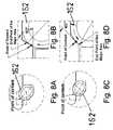
- FIGS. 1A–1Hillustrate interaction between a canted coil spring and dynamic surfaces
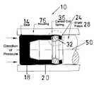
- FIG. 2is a side/cross sectional view of a snap-unlocking, latching cover seal in accordance with the present invention generally showing a seal body with an extended cylindrical sleeve, a piston, a biasing element, and surfaces for effecting sealing between the housing and the sleeve as well as an axial force to provide locking and latching;
- FIGS. 2A and 2Bare enlarged diagrams of the biasing elements in relative position between an endpoint of a major axis of the spring and a point of contact in order to provide locking between the cover seal and the piston;
- FIGS. 2C and 2Dprovide enlarged views showing orientation of the surface to provide the latching between a cover seal and a piston, the difference between the latching and locking being hereinafter described in greater detail;
- FIG. 3is similar to the seal apparatus shown in FIG. 2 further including a biasing element comprising a spring filled with an elastomer;
- FIGS. 3A and 3Bare enlarged drawings of the surfaces shown in FIG. 3 and correspond to FIGS. 1A and 1B and illustrates surfaces for locking of the seal to the piston;
- FIGS. 3C and 3Dare similar to FIGS. 2C and 2D illustrating surfaces providing latching between the seal and the pistons;
- FIG. 4is an alternative embodiment of the present invention utilizing an O-ring alone as the biasing element for providing latching between the seal and the piston, 3 A showing an enlarged diagram of the surface of an O-ring;
- FIG. 5is an alternative embodiment of the present invention utilizing a surfaces for locking the seal to the piston as shown in FIGS. 5A and 5B and latching the seal to the piston shown in FIGS. 5C and 5D ;
- FIGS. 6 , 6 A, 6 B, 6 C, 6 Dare similar to the seal and the piston shown in FIG. 4 again showing differences in surfaces for providing locking and latching of the seal to the piston;
- FIG. 7is a view of an alternative embodiment of the present invention similar to FIG. 6 using however an O-ring as a biasing element;
- FIGS. 8 , 8 A, 8 B, 8 C, 8 Dillustrate a seal apparatus in accordance with the present invention in which the latching/locking biasing element is disposed in a cylindrical portion in the seal;
- FIGS. 9 , 9 A, 9 B, 9 C, 9 Dis a design similar to that shown in FIG. 8 except that a spring loaded O-ring, that is, a spring filled with an elastomer is utilized;
- FIG. 10is a design which an O-ring is used as a latching element
- FIGS. 11 , 11 A, 11 B, 11 C, 11 Dillustrate a bi-directional seal that can effect sealing in both directions
- FIGS. 12 , 12 A, 12 B, 12 C, 12 Dis similar to that shown in FIG. 11 utilizing a spring loaded O-ring;
- FIGS. 13 , 13 A, 13 B, 13 Cillustrate a snap-on cover seal for low and high pressure applications with a canted coil spring utilized for locking and loading at low pressure and a spring loaded O-ring utilized for higher pressure applications;
- FIGS. 14 , 14 A, 14 B, 14 Cillustrates a cover seal wherein permanent locking occurs between the piston and the seal.
- a canted coil springincludes elliptical coils and a dynamic surface contacts the spring coils as shown. As the dynamic surface moves against the spring, the spring tends to rotate or to rotate. The end of the minor axis that is in the contact quadrant tends to rotate or to rotate towards the contact point.
- the rotationis dependent upon the dynamic surface contact angle and its direction of travel as well as the spring groove configuration.
- seal apparatus 10in accordance with the present invention generally including a cover seal 14 having a body 18 and an extending cylindrical sleeve 20 having a radial internal groove 24 therein.
- a piston 28is provided which includes a circumferential groove 32 an elliptical spring 36 provides a biasing element and is disposed between the internal groove 24 and the circumferential groove 32 .
- surfaces including a generally right angle shoulder 40 formed in the internal groove 24 and an opposing angled shoulder 44 formed in the circumferential groove 32orient the spring 36 so that a point of contact between the elliptical spring 36 and the angled shoulder 44 is above an endpoint of a major axis of the spring 36 which provides locking between the seal 14 and the piston 28 which at the same time providing an axial force between the seal 14 and piston 28 to prevent movement along a longitudinal axis 50 of the seal 14 and piston 28 , see FIG. 2 .
- FIG. 2Bmost clearly shows the relative positioning between the point of contact and the endpoint 54 of the major axis 56 .
- a point of contact 60is a point at which the spring 36 contacts the surface 44 . Terminology of these points is also included in the drawings for clarity. As shown in FIG. 6 , when the angled surface 44 is at 60°, a point of contact 60 is above the endpoint of the major axis 54 and the seal 14 is locked to the piston 28 .
- lockingis meant to be the permanent retention of the seal 14 to the piston 28 .
- Latchingis defined as holding a seal 14 to the piston 28 within a specific force range that allows the seal 14 and piston 28 to disengage without damage to the spring 36 .
- the spring 36also provides sealing in between a housing 78 and the piston 28 , see FIG. 2 .
- the structure of the seal apparatus 10provides for easy assembly of the seal 14 onto the piston 28 and provides for latching or locking, as hereinabove noted. Also hereinabove noted, the structure of the present invention also provides for an absence of axial play between the seal 14 and the piston 28 . The higher the spring force the lower the possibility of axial play between the seal 14 and the piston 28 and also higher radial force to affect sealing between the seal 14 and the housing 76 .
- FIGS. 3 , 3 A, 3 B, 3 C, 3 Dthere is shown an alternative embodiment 80 .
- the present inventionutilizing a canted coil spring filled with an elastomer, or spring loaded O-ring, 84 .
- Common reference numbers in FIG. 2represent identical or substantially similar components to those hereinbefore discussed in connection with the seal apparatus 10 shown in FIG. 2 , the latching and locking surface arrangements are shown in FIGS. 3A–3D correspond to those shown in FIGS. 2A–2D .
- a spring loaded O-ring 84provides more even distribution of the force acting on the seal 14 , thus enhancing sealing ability between the seal 14 and the housing 78 .
- a more even distribution of the forcereduces stress concentrations along the latching, locking areas, thus reducing the possibility of axial movement during operation, especially when giving the soft materials such as PTFE or PTFE composition.
- a soft derometer, for example, 30will allow the elastomer to flow into open spaces within the groove cavity, which will result in lower forces being developed and providing a lower latching force at disconnect.
- the seal 10will generate a lower radial sealing force between the seal 14 and the housing 76 .
- a higher derometerwill do the opposite, thus increasing the force developed, resulting in increase latching force and increased sealing ability.
- FIG. 4there is an alternative embodiment 88 in accordance with the present invention utilizing an O-ring 92 as a latching means.
- the degree of latchingwill depend upon the derometer of the O-ring. The lower the derometer, the lower the latching force required to latch and disconnect, where a higher derometer will increase the force required to latch and disconnect.
- An enlarged view of the O-ring 92 within the grooves 24 , 32is shown in FIG. 3A .
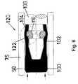
- an alternative embodiment 96 of the present inventiongenerally including a cover seal 98 having a body 100 and a sleeve 102 , the sleeve 102 having a groove 104 , a piston 108 includes a groove 110 , and a spring 112 is disposed within the grooves 104 , as shown in FIGS. 5A–5D .
- the circumferential groove 110includes a generally right angled shoulder 114 and the internal groove includes an opposing angled shoulder 116 for orienting the spring 112 with a point of contact between the elliptical spring and the angled shoulder disposed below the endpoint of the major axis to provide locking seal 98 and piston together.
- FIGS. 5C–5DA latching configuration is shown in FIGS. 5C–5D .
- FIGS. 6 , 6 A– 6 Dwhich is similar to the embodiment 96 except that an elastomer filled spring 122 is utilized.
- Common reference numbersrefer to identical or substantial similar structure hereinabove discussed in connection with the embodiment 96 shown in FIGS. 5 , 5 A– 5 D.
- FIG. 7shows the same type of design but utilizing an O-ring 126 for latching, see FIG. 6A for details of the O-ring 126 positioning.
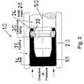
- FIGS. 8 , 8 A– 8 Dshow still another embodiment 120 of a seal 132 for a uni-directional high pressure application which includes a body 134 and an extending cylindrical portion 136 having a circumferential groove 138 , a piston 142 includes a bore 144 with a radial internal groove 148 therein all disposed within a housing 152 .
- a canted coil spring 164provides a biasing element and is disposed within the grooves 138 , 148 .
- a surface 164 in the circumferential groove 138 along with surface 166 disposed in the internal groove 148orient the spring 162 in order to effect latching or locking between the piston 142 and the seal 132 .
- the position of the springdetermines the manner in which locking or latching action will occur, as hereinabove described and illustrated in FIGS. 8A , 8 B, 8 C, and 8 D.
- FIG. 9there is shown another embodiment 170 in accordance with the present invention which is of a design similar to the embodiment 130 shown in FIG. 7 with the exception that a spring loaded O-ring 174 is utilized.
- Other elements of the embodiment 170 indicated by the character referencesare identical or substantially similar to those hereinabove discussed in connection with the embodiment 130 of FIG. 8 .
- FIGS. 9A–9Billustrate the function of the surfaces as hereinabove discussed in connection with the earlier presented embodiments.
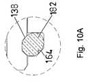
- FIGS. 10 and 10Ashow yet another embodiment 180 similar to that shown in FIGS. 8 and 9 except that an O-ring 182 is utilized as the latching means between the piston 142 and the seal 132 .
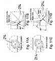
- FIGS. 11 and 12show bi-directional low pressure seal apparatus 186 , 188 respectively each including a cover seal 192 with a body 194 with a sleeve 196 having an internal groove 198 along with a groove 202 circumferentially formed in a piston 204 and a surfaces 208 , 210 for orienting canted coil spring 214 (see FIG. 11 ) or an elastomer filled spring 216 (see FIG. 12 ) in order to provide both sealing between the sleeve 196 and a housing 220 .
- FIGS. 11A–11D and 12 A– 12 Dshowing orientations similar to that hereinbefore discussed or providing either latching or loading between seal 192 and piston 204 . Accordingly, a repeat of that description is not repeated for the sake of brevity.
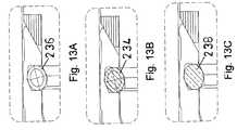
- FIG. 13shows an embodiment 224 having a snap on cover seal 226 for both low and high pressure applications for sealing between a reciprocating piston 228 and housing 230 .
- FIGS. 13 and 13Bshow a spring loaded O-ring 234 as the locking means
- FIG. 12Ashows the canted coil spring 236 as a locking means
- FIG. 12Cillustrates an O-ring 238 as a latching means. Operation of the seal apparatus as hereinabove described in connection with the earlier presented embodiments.
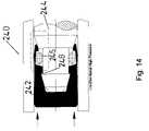
- FIG. 14illustrates seal apparatus 240 including a cover seal 242 and piston 244 along with a spring 246 for providing permanent locking between the piston 244 and the seal 242 .
- This particular designis normally used in small diameters due to space requirements and conditions of relatively low pressure to perhaps 100 psi.
- the locking between the piston 244 and the seal 242is accomplished through the elasticity of the seal which is forced over a notch 248 on the piston 244 , a seal 242 is loaded by the O-ring 246 also shown in FIG. 13A , a spring loaded O-ring 250 .
Landscapes
- Engineering & Computer Science (AREA)
- General Engineering & Computer Science (AREA)
- Mechanical Engineering (AREA)
- Chemical & Material Sciences (AREA)
- Combustion & Propulsion (AREA)
- Sealing Devices (AREA)
- Diaphragms And Bellows (AREA)
Abstract
Description
Claims (5)
Priority Applications (3)
| Application Number | Priority Date | Filing Date | Title |
|---|---|---|---|
| US11/058,864US7210398B2 (en) | 2004-02-18 | 2005-02-16 | Cover seals with latching locking features |
| PCT/US2005/005050WO2005079456A2 (en) | 2004-02-18 | 2005-02-17 | Cover seals with latching locking features |
| EP05713726AEP1784593B1 (en) | 2004-02-18 | 2005-02-17 | Cover seals with latching locking features |
Applications Claiming Priority (2)
| Application Number | Priority Date | Filing Date | Title |
|---|---|---|---|
| US54580804P | 2004-02-18 | 2004-02-18 | |
| US11/058,864US7210398B2 (en) | 2004-02-18 | 2005-02-16 | Cover seals with latching locking features |
Publications (2)
| Publication Number | Publication Date |
|---|---|
| US20050212218A1 US20050212218A1 (en) | 2005-09-29 |
| US7210398B2true US7210398B2 (en) | 2007-05-01 |
Family
ID=34988865
Family Applications (1)
| Application Number | Title | Priority Date | Filing Date |
|---|---|---|---|
| US11/058,864Expired - LifetimeUS7210398B2 (en) | 2004-02-18 | 2005-02-16 | Cover seals with latching locking features |
Country Status (3)
| Country | Link |
|---|---|
| US (1) | US7210398B2 (en) |
| EP (1) | EP1784593B1 (en) |
| WO (1) | WO2005079456A2 (en) |
Cited By (27)
| Publication number | Priority date | Publication date | Assignee | Title |
|---|---|---|---|---|
| US20080254670A1 (en)* | 2007-04-13 | 2008-10-16 | Balsells Peter J | Electrical connectors with improved electrical contact performance |
| US20090045583A1 (en)* | 2005-12-02 | 2009-02-19 | Vesa Ropponen | Ring Sealing Between Sliding Surfaces |
| US20090160139A1 (en)* | 2007-12-21 | 2009-06-25 | Balsells Pete J | Locking mechanism with quick disassembly means |
| US20090289418A1 (en)* | 2008-05-23 | 2009-11-26 | Cook Hugh Q | Rotary seals |
| US20100107829A1 (en)* | 2008-10-30 | 2010-05-06 | Nemcomed, Inc. | Torque limiting driver |
| US20100217274A1 (en)* | 2005-04-15 | 2010-08-26 | Abbott Medical Optics Inc. | Multi-action device for inserting an intraocular lens into an eye |
| US20110037234A1 (en)* | 2009-08-12 | 2011-02-17 | Pete Balsells | Cartridge seal assemblies and associated methods |
| US8428724B2 (en) | 2011-03-11 | 2013-04-23 | Greatbatch Ltd. | Low insertion force electrical connector for implantable medical devices |
| US20140053639A1 (en)* | 2011-04-25 | 2014-02-27 | Waters Technologies Corporation | Fitting Assemblies |
| US9194497B2 (en) | 2013-09-03 | 2015-11-24 | Bal Seal Engineering, Inc. | Elastic seals with dynamic lips and related methods |
| US20180119857A1 (en)* | 2016-10-31 | 2018-05-03 | Bal Seal Engineering, Inc. | Axial and radial floating seals |
| US10117366B2 (en) | 2015-12-14 | 2018-10-30 | Bal Seal Engineering, Inc. | Spring energized seals and related methods |
| US10125872B2 (en) | 2011-08-18 | 2018-11-13 | Bal Seal Engineering, Inc. | Reciprocating seal for high pulsating pressure |
| US10184564B2 (en)* | 2015-02-02 | 2019-01-22 | Bal Seal Engineering, Inc. | Seal assemblies and related methods |
| US10460977B2 (en) | 2016-09-29 | 2019-10-29 | Lam Research Corporation | Lift pin holder with spring retention for substrate processing systems |
| US10520091B2 (en) | 2009-07-08 | 2019-12-31 | Bal Seal Engineering, Inc. | Double direction seal with locking |
| US10520092B2 (en) | 2016-10-24 | 2019-12-31 | Bal Seal Engineering, Inc. | Seal assemblies for extreme temperatures and related methods |
| US10598241B2 (en) | 2014-02-26 | 2020-03-24 | Bal Seal Engineering, Inc. | Multi deflection canted coil springs and related methods |
| US10900531B2 (en) | 2017-08-30 | 2021-01-26 | Bal Seal Engineering, Llc | Spring wire ends to faciliate welding |
| US11353079B2 (en) | 2017-10-05 | 2022-06-07 | Bal Seal Engineering, Llc | Spring assemblies, applications of spring assemblies, and related methods |
| US11480250B2 (en) | 2017-03-16 | 2022-10-25 | Bal Seal Engineering, Llc | V-springs and seals with v-springs |
| US11536373B2 (en) | 2016-03-07 | 2022-12-27 | Bal Seal Engineering, Llc | Seal assemblies and related methods |
| US11680642B2 (en) | 2018-05-08 | 2023-06-20 | Bal Seal Engineering, Llc | Seal assemblies and related methods |
| US11746906B1 (en) | 2022-11-01 | 2023-09-05 | Bal Seal Engineering, Llc | Lip seals and related methods |
| US11940049B1 (en) | 2022-11-01 | 2024-03-26 | Bal Seal Engineering, Llc | Lip seals and related methods |
| US12092160B2 (en) | 2021-09-23 | 2024-09-17 | Bal Seal Engineering Llc | Integrated seal and bearing assembly and related methods |
| US12247663B2 (en) | 2022-11-01 | 2025-03-11 | Bal Seal Engineering, Llc | Lip seals and related methods |
Families Citing this family (8)
| Publication number | Priority date | Publication date | Assignee | Title |
|---|---|---|---|---|
| JP5248414B2 (en)* | 2009-05-27 | 2013-07-31 | 株式会社東芝 | Switch |
| FR2991409B1 (en) | 2012-06-01 | 2021-01-01 | Bal Seal Eng Inc | SLOTTED CONNECTORS PROVIDED WITH RETAINING MECHANISMS |
| US9829028B2 (en)* | 2012-11-15 | 2017-11-28 | Bal Seal Engineering, Inc. | Connectors with a pin, a housing, and one or more springs |
| US9312630B2 (en) | 2012-12-21 | 2016-04-12 | Bal Seal Engineering, Inc. | Locking connectors and related methods |
| US20150362074A1 (en)* | 2013-02-20 | 2015-12-17 | Nok Corporation | Sealing device |
| WO2015125032A1 (en)* | 2014-02-19 | 2015-08-27 | A.T.P. S.P.A. | Dosing piston |
| US10181668B2 (en) | 2016-06-24 | 2019-01-15 | Bal Seal Engineering, Inc. | Spring contacts and related methods |
| US10604995B2 (en)* | 2017-06-22 | 2020-03-31 | Sejong Pharmatech Co., Ltd. | Sealing door and method of forming channel |
Citations (5)
| Publication number | Priority date | Publication date | Assignee | Title |
|---|---|---|---|---|
| US3820739A (en)* | 1971-02-27 | 1974-06-28 | Rieter Ag Maschf | Apparatus for holding and centering a tube on a bobbin holder |
| US4678210A (en)* | 1986-08-15 | 1987-07-07 | Peter J. Balsells | Loading and locking mechanism |
| US4804290A (en) | 1986-08-22 | 1989-02-14 | Peter J. Balsells | Latching and sealing device |
| US5161806A (en)* | 1990-12-17 | 1992-11-10 | Peter J. Balsells | Spring-loaded, hollow, elliptical ring seal |
| US20030157846A1 (en)* | 2002-02-15 | 2003-08-21 | Daniel Poon | Medically implantable electrical connector with constant conductivity |
- 2005
- 2005-02-16USUS11/058,864patent/US7210398B2/ennot_activeExpired - Lifetime
- 2005-02-17WOPCT/US2005/005050patent/WO2005079456A2/enactiveApplication Filing
- 2005-02-17EPEP05713726Apatent/EP1784593B1/ennot_activeExpired - Lifetime
Patent Citations (5)
| Publication number | Priority date | Publication date | Assignee | Title |
|---|---|---|---|---|
| US3820739A (en)* | 1971-02-27 | 1974-06-28 | Rieter Ag Maschf | Apparatus for holding and centering a tube on a bobbin holder |
| US4678210A (en)* | 1986-08-15 | 1987-07-07 | Peter J. Balsells | Loading and locking mechanism |
| US4804290A (en) | 1986-08-22 | 1989-02-14 | Peter J. Balsells | Latching and sealing device |
| US5161806A (en)* | 1990-12-17 | 1992-11-10 | Peter J. Balsells | Spring-loaded, hollow, elliptical ring seal |
| US20030157846A1 (en)* | 2002-02-15 | 2003-08-21 | Daniel Poon | Medically implantable electrical connector with constant conductivity |
Cited By (37)
| Publication number | Priority date | Publication date | Assignee | Title |
|---|---|---|---|---|
| US20100217274A1 (en)* | 2005-04-15 | 2010-08-26 | Abbott Medical Optics Inc. | Multi-action device for inserting an intraocular lens into an eye |
| US8926628B2 (en)* | 2005-04-15 | 2015-01-06 | Abbott Medical Optics Inc. | Multi-action device for inserting an intraocular lens into an eye |
| US20090045583A1 (en)* | 2005-12-02 | 2009-02-19 | Vesa Ropponen | Ring Sealing Between Sliding Surfaces |
| US20080254670A1 (en)* | 2007-04-13 | 2008-10-16 | Balsells Peter J | Electrical connectors with improved electrical contact performance |
| US7914351B2 (en)* | 2007-04-13 | 2011-03-29 | Bal Seal Engineering | Electrical connectors with improved electrical contact performance |
| US8308167B2 (en)* | 2007-12-21 | 2012-11-13 | Bal Seal Engineering, Inc. | Locking mechanism with quick disassembly means |
| US20090160139A1 (en)* | 2007-12-21 | 2009-06-25 | Balsells Pete J | Locking mechanism with quick disassembly means |
| US20090289418A1 (en)* | 2008-05-23 | 2009-11-26 | Cook Hugh Q | Rotary seals |
| US8096559B2 (en) | 2008-05-23 | 2012-01-17 | Bal Seal Engineering, Inc. | Rotary seals |
| US20100107829A1 (en)* | 2008-10-30 | 2010-05-06 | Nemcomed, Inc. | Torque limiting driver |
| US10520091B2 (en) | 2009-07-08 | 2019-12-31 | Bal Seal Engineering, Inc. | Double direction seal with locking |
| US8684362B2 (en)* | 2009-08-12 | 2014-04-01 | Bal Seal Engineering, Inc. | Cartridge seal assemblies and associated methods |
| US20110037234A1 (en)* | 2009-08-12 | 2011-02-17 | Pete Balsells | Cartridge seal assemblies and associated methods |
| US9285034B2 (en) | 2009-08-12 | 2016-03-15 | Bal Seal Engineering, Inc. | Cartridge seal assemblies and associated methods |
| US8428724B2 (en) | 2011-03-11 | 2013-04-23 | Greatbatch Ltd. | Low insertion force electrical connector for implantable medical devices |
| US8934974B2 (en) | 2011-03-11 | 2015-01-13 | Greatbatch Ltd. | Low insertion force electrical connector for implantable medical devices |
| US9037243B2 (en) | 2011-03-11 | 2015-05-19 | Greatbatch Ltd. | Low insertion force electrical connector for implantable medical devices |
| US9618483B2 (en)* | 2011-04-25 | 2017-04-11 | Waters Technologies Corporation | Fitting assemblies |
| US20140053639A1 (en)* | 2011-04-25 | 2014-02-27 | Waters Technologies Corporation | Fitting Assemblies |
| US10125872B2 (en) | 2011-08-18 | 2018-11-13 | Bal Seal Engineering, Inc. | Reciprocating seal for high pulsating pressure |
| US9194497B2 (en) | 2013-09-03 | 2015-11-24 | Bal Seal Engineering, Inc. | Elastic seals with dynamic lips and related methods |
| US10598241B2 (en) | 2014-02-26 | 2020-03-24 | Bal Seal Engineering, Inc. | Multi deflection canted coil springs and related methods |
| US10184564B2 (en)* | 2015-02-02 | 2019-01-22 | Bal Seal Engineering, Inc. | Seal assemblies and related methods |
| US10117366B2 (en) | 2015-12-14 | 2018-10-30 | Bal Seal Engineering, Inc. | Spring energized seals and related methods |
| US11536373B2 (en) | 2016-03-07 | 2022-12-27 | Bal Seal Engineering, Llc | Seal assemblies and related methods |
| US10460977B2 (en) | 2016-09-29 | 2019-10-29 | Lam Research Corporation | Lift pin holder with spring retention for substrate processing systems |
| US10520092B2 (en) | 2016-10-24 | 2019-12-31 | Bal Seal Engineering, Inc. | Seal assemblies for extreme temperatures and related methods |
| US20180119857A1 (en)* | 2016-10-31 | 2018-05-03 | Bal Seal Engineering, Inc. | Axial and radial floating seals |
| US10989305B2 (en)* | 2016-10-31 | 2021-04-27 | Bal Seal Engineering, Llc | Axial and radial floating seals |
| US11480250B2 (en) | 2017-03-16 | 2022-10-25 | Bal Seal Engineering, Llc | V-springs and seals with v-springs |
| US10900531B2 (en) | 2017-08-30 | 2021-01-26 | Bal Seal Engineering, Llc | Spring wire ends to faciliate welding |
| US11353079B2 (en) | 2017-10-05 | 2022-06-07 | Bal Seal Engineering, Llc | Spring assemblies, applications of spring assemblies, and related methods |
| US11680642B2 (en) | 2018-05-08 | 2023-06-20 | Bal Seal Engineering, Llc | Seal assemblies and related methods |
| US12092160B2 (en) | 2021-09-23 | 2024-09-17 | Bal Seal Engineering Llc | Integrated seal and bearing assembly and related methods |
| US11746906B1 (en) | 2022-11-01 | 2023-09-05 | Bal Seal Engineering, Llc | Lip seals and related methods |
| US11940049B1 (en) | 2022-11-01 | 2024-03-26 | Bal Seal Engineering, Llc | Lip seals and related methods |
| US12247663B2 (en) | 2022-11-01 | 2025-03-11 | Bal Seal Engineering, Llc | Lip seals and related methods |
Also Published As
| Publication number | Publication date |
|---|---|
| EP1784593A2 (en) | 2007-05-16 |
| EP1784593A4 (en) | 2011-03-16 |
| WO2005079456A3 (en) | 2007-05-18 |
| EP1784593B1 (en) | 2012-09-26 |
| US20050212218A1 (en) | 2005-09-29 |
| WO2005079456A2 (en) | 2005-09-01 |
Similar Documents
| Publication | Publication Date | Title |
|---|---|---|
| US7210398B2 (en) | Cover seals with latching locking features | |
| EP0942209B1 (en) | Rotary cartridge seals with retainer | |
| KR950006383Y1 (en) | Seal ring | |
| US5992856A (en) | Rotary, reciprocating seals with double spring and separating band rings | |
| US7828300B2 (en) | Sealing device for reciprocating shaft | |
| JPWO2006126451A1 (en) | Lip type seal | |
| CA2065733C (en) | Annular support for a seal for a tilt piston | |
| JP4853633B2 (en) | Sealing device | |
| US9746080B2 (en) | High pressure seal assembly for a moveable shaft | |
| MXPA05001560A (en) | Spark plug tube seal. | |
| EP1950473B1 (en) | Carbon dioxide gas sealing enclosed device | |
| JP4243120B2 (en) | High pressure gas sealed structure | |
| US11732801B2 (en) | Self-contained low load narrow groove seal | |
| US4227705A (en) | Semicircular plug for preventing leakage of oil in a cylinder head of an overhead cam shaft engine | |
| JP3498554B2 (en) | Sealing device | |
| JP5066787B2 (en) | Sealing structure | |
| WO2018180307A1 (en) | Arrangement structure for seal material | |
| JP2581284Y2 (en) | Cap seal | |
| JPH07133866A (en) | Cylinder device | |
| JP4143786B2 (en) | Sealing device | |
| JP6660759B2 (en) | Sealing device | |
| JP3965785B2 (en) | Sealing device | |
| JPH11141688A (en) | Sealing device | |
| JPH0628309U (en) | Sealing device for rotary actuator | |
| JPH0247313Y2 (en) |
Legal Events
| Date | Code | Title | Description |
|---|---|---|---|
| AS | Assignment | Owner name:BAL SEAL ENGINEERING CO., INC., CALIFORNIA Free format text:ASSIGNMENT OF ASSIGNORS INTEREST;ASSIGNOR:BALSELLS, PETER J.;REEL/FRAME:016539/0471 Effective date:20050714 | |
| STCF | Information on status: patent grant | Free format text:PATENTED CASE | |
| FPAY | Fee payment | Year of fee payment:4 | |
| FPAY | Fee payment | Year of fee payment:8 | |
| MAFP | Maintenance fee payment | Free format text:PAYMENT OF MAINTENANCE FEE, 12TH YEAR, LARGE ENTITY (ORIGINAL EVENT CODE: M1553); ENTITY STATUS OF PATENT OWNER: LARGE ENTITY Year of fee payment:12 | |
| AS | Assignment | Owner name:JPMORGAN CHASE BANK, N.A., AS COLLATERAL AGENT, ILLINOIS Free format text:AMENDED AND RESTATED PATENT COLLATERAL SECURITY AND PLEDGE AGREEMENT;ASSIGNORS:KAMATICS CORPORATION;BAL SEAL ENGINEERING, LLC;REEL/FRAME:054304/0388 Effective date:20200915 | |
| AS | Assignment | Owner name:MORGAN STANLEY SENIOR FUNDING, INC., AS COLLATERAL AGENT, NEW YORK Free format text:IP SECURITY AGREEMENT;ASSIGNORS:KAMAN CORPORATION;KAMAN AEROSPACE CORPORATION;BAL SEAL ENGINEERING, LLC;AND OTHERS;REEL/FRAME:067175/0740 Effective date:20240419 | |
| AS | Assignment | Owner name:AIRCRAFT WHEEL AND BRAKE, LLC, OHIO Free format text:RELEASE BY SECURED PARTY;ASSIGNOR:JPMORGAN CHASE BANK, N.A., AS COLLATERAL AGENT;REEL/FRAME:067200/0800 Effective date:20240419 Owner name:BAL SEAL ENGINEERING, LLC, CALIFORNIA Free format text:RELEASE BY SECURED PARTY;ASSIGNOR:JPMORGAN CHASE BANK, N.A., AS COLLATERAL AGENT;REEL/FRAME:067200/0800 Effective date:20240419 Owner name:KAMATICS CORPORATION, CONNECTICUT Free format text:RELEASE BY SECURED PARTY;ASSIGNOR:JPMORGAN CHASE BANK, N.A., AS COLLATERAL AGENT;REEL/FRAME:067200/0800 Effective date:20240419 | |
| AS | Assignment | Owner name:KAMATICS CORPORATION, CONNECTICUT Free format text:RELEASE OF INTELLECTUAL PROPERTY SECURITY AGREEMENTS (PATENTS) AT REEL 067175/FRAME 0740;ASSIGNOR:MORGAN STANLEY SENIOR FUNDING, INC.;REEL/FRAME:070347/0014 Effective date:20250226 Owner name:AIRCRAFT WHEEL AND BRAKE, LLC, NEW YORK Free format text:RELEASE OF INTELLECTUAL PROPERTY SECURITY AGREEMENTS (PATENTS) AT REEL 067175/FRAME 0740;ASSIGNOR:MORGAN STANLEY SENIOR FUNDING, INC.;REEL/FRAME:070347/0014 Effective date:20250226 Owner name:BAL SEAL ENGINEERING, LLC, CALIFORNIA Free format text:RELEASE OF INTELLECTUAL PROPERTY SECURITY AGREEMENTS (PATENTS) AT REEL 067175/FRAME 0740;ASSIGNOR:MORGAN STANLEY SENIOR FUNDING, INC.;REEL/FRAME:070347/0014 Effective date:20250226 Owner name:KAMAN AEROSPACE CORPORATION, CONNECTICUT Free format text:RELEASE OF INTELLECTUAL PROPERTY SECURITY AGREEMENTS (PATENTS) AT REEL 067175/FRAME 0740;ASSIGNOR:MORGAN STANLEY SENIOR FUNDING, INC.;REEL/FRAME:070347/0014 Effective date:20250226 Owner name:KAMAN CORPORATION, CONNECTICUT Free format text:RELEASE OF INTELLECTUAL PROPERTY SECURITY AGREEMENTS (PATENTS) AT REEL 067175/FRAME 0740;ASSIGNOR:MORGAN STANLEY SENIOR FUNDING, INC.;REEL/FRAME:070347/0014 Effective date:20250226 Owner name:CITIBANK, N.A., AS COLLATERAL AGENT, NEW YORK Free format text:SECURITY INTEREST;ASSIGNORS:X-MICROWAVE, LLC;TANTALUM PELLET COMPANY, LLC;EVANS CAPACITOR COMPANY, LLC;AND OTHERS;REEL/FRAME:070344/0430 Effective date:20250226 |