US7210270B1 - Partition system with elevated raceway - Google Patents
Partition system with elevated racewayDownload PDFInfo
- Publication number
- US7210270B1 US7210270B1US09/692,663US69266300AUS7210270B1US 7210270 B1US7210270 B1US 7210270B1US 69266300 AUS69266300 AUS 69266300AUS 7210270 B1US7210270 B1US 7210270B1
- Authority
- US
- United States
- Prior art keywords
- partition
- raceway
- frame
- support
- partition frame
- Prior art date
- Legal status (The legal status is an assumption and is not a legal conclusion. Google has not performed a legal analysis and makes no representation as to the accuracy of the status listed.)
- Expired - Fee Related, expires
Links
Images


Classifications
- H—ELECTRICITY
- H02—GENERATION; CONVERSION OR DISTRIBUTION OF ELECTRIC POWER
- H02G—INSTALLATION OF ELECTRIC CABLES OR LINES, OR OF COMBINED OPTICAL AND ELECTRIC CABLES OR LINES
- H02G3/00—Installations of electric cables or lines or protective tubing therefor in or on buildings, equivalent structures or vehicles
- H02G3/30—Installations of cables or lines on walls, floors or ceilings
- H—ELECTRICITY
- H02—GENERATION; CONVERSION OR DISTRIBUTION OF ELECTRIC POWER
- H02G—INSTALLATION OF ELECTRIC CABLES OR LINES, OR OF COMBINED OPTICAL AND ELECTRIC CABLES OR LINES
- H02G3/00—Installations of electric cables or lines or protective tubing therefor in or on buildings, equivalent structures or vehicles
- H02G3/02—Details
- H02G3/04—Protective tubing or conduits, e.g. cable ladders or cable troughs
- H02G3/0425—Plinths
Definitions
- Modern officesare becoming increasingly complicated and sophisticated due largely to the ever increasing needs of the users for improved utilities support at each workstation, such as communications, computers and other types of data processors, electronic displays, etc., including physical accommodations, such as lighting, HVAC, security, and the like.
- modern offices for highly skilled “knowledge workers”such as engineers, accountants, stock brokers, computer programmers, etc.
- Such equipmenthas very stringent power and signal requirements, and must quickly and efficiently interface with related equipment at both adjacent and remote locations.
- Work areas with readily controllable lighting, HVAC, sound masking, and other physical support systemsare also highly desirable to maximize worker creativity and productivity.
- Many other types of high technology equipment and facilitiesare also presently being developed which will find their place in the workplaces of the future.
- utilitiesincorporates a wide variety of facilities for use at a workstation, including security devices, electrical power, signal and/or communications, HVAC, water and other fluids, and other similar resources. The ability to provide the worker with ready access to all of these utilities is clearly advantageous in the quest to promote worker well being and effectiveness.
- Open office planshave been developed to reduce overall officing costs, and generally incorporate large, open floor spaces in buildings that are equipped with modular furniture systems which are readily reconfigurable to accommodate the ever changing needs of a specific user, as well as the divergent requirements of different tenants.
- One arrangement commonly used for furnishing open plansincludes movable partition panels that are detachably interconnected to partition off the open spaces into individual workstations and/or offices.
- Such partition panelsare configured to receive hang-on furniture units, such as worksurfaces, overhead cabinets, shelves, etc., and are generally known in the office furniture industry as “systems furniture”.
- Another arrangement for dividing and/or partitioning open plansincludes modular furniture arrangements, in which a plurality of differently shaped, freestanding furniture units are positioned in a side-by-side relationship, with upstanding privacy screens attached to at least some of the furniture units to create individual, distinct workstations and/or offices.
- modular furniture arrangementsin which a plurality of differently shaped, freestanding furniture units are positioned in a side-by-side relationship, with upstanding privacy screens attached to at least some of the furniture units to create individual, distinct workstations and/or offices.
- some types of modular furniture systemssuch as selected portable partition panels and freestanding furniture units can be equipped with an optional powerway, which extends along the entire width of the unit, and has quick-disconnect connectors adjacent opposite ends thereof to connect with adjacent, like powerways, and thereby provide electrical power to an associated furniture group or cluster.
- Outlet receptaclesare provided along each powerway into which electrical appliances can be plugged.
- Cable troughs or channelsare also provided in most such furniture units, so as to form a system of interconnected raceways into which signal and communications wires can be routed.
- Such cablingis normally routed through the furniture system after the furniture units are installed, and is then hard wired at each of the desired outlets.
- One aspect of the present inventionis to provide an elevated raceway for routing utility lines in a vertically spaced relationship above the upper edge of a partition.
- the racewayincludes an elongated passageway configured to retain utility lines in a horizontally extending manner.
- a first support memberextends downwardly from the raceway, and has a connector spaced apart from the raceway a first vertical distance.
- the connectoris configured to attach to a partition frame.
- a second support memberextends downwardly from the raceway, and has a connector spaced apart from the raceway a second vertical distance that is different from the first vertical distance, such that the raceway is supported at a generally uniform vertical height above an upper edge of a partition having sections with different heights.
- a partitionincluding a partition frame having a horizontally extending upper frame defining an upper edge of the partition frame.
- the partition framefurther includes a pair of horizontally spaced apart vertical frame members, each having an upper end thereof secured to the upper frame member.
- the partition framehas a lower portion configured to abuttingly support the partition frame freestanding on a floor surface.
- the partitionfurther includes a horizontally extending raceway defining an elongated passageway configured to retain utility lines in a horizontally extending manner.
- a vertically extending support memberis connected to the partition frame, and supports the raceway vertically spaced above the upper frame member.
- Yet another aspect of the present inventionis a partition system including a first partition frame having a first side edge and including a lower portion configured to abuttingly support the first partition frame section freestanding on a floor surface.
- the first partition framehas a horizontal upper edge.
- the partition systemalso includes a second partition frame having a second side edge connected to the first side edge.
- the second partition framealso includes a lower portion configured to abuttingly support the second partition frame freestanding on a floor surface.
- the second partition framehas a horizontal upper edge.
- the first and second partition frameshave different heights such that the upper edges are positioned at different elevations when the first and second partition frames are positioned on a floor surface.
- An elongated elevated duct or racewayis configured to support horizontally extending utility lines.
- the racewayincludes a support member connected to the partition frame and supporting the raceway vertically spaced above the upper edges of the first and second partition frames.
- a partition panelincluding a generally rectangular partition frame having a base configured to support the partition frame freestanding on a floor surface.
- the partition framehas a horizontal upper edge.
- the partition panelalso includes a pair of vertical extension members, each having a vertically elongated opening therethrough.
- a sheetextends upwardly above the upper edge of the partition frame, and is disposed within the vertically elongated openings to retain the sheet in a vertically extending configuration.
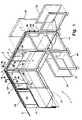
- FIG. 1is a partially exploded, perspective view showing a partition system including an elevated raceway according to the present invention
- FIG. 2is a front elevational view of a partition system including partitions of varying size, each of which incorporates an elevated raceway;
- FIG. 3is a cross-sectional view of the raceway taken along the line III—III; FIG. 1 ;
- FIG. 4is a cross-sectional view of a second embodiment of the raceway taken along the line IV—IV; FIG. 1 ;
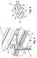
- FIG. 5is a fragmentary, perspective view showing a first embodiment of a bracket for connecting the raceway to the horizontal row of slots of the partition of FIG. 1 ;
- FIG. 6is a perspective view of the bracket of FIG. 5 ;
- FIG. 7is a fragmentary, perspective view of a second embodiment of a bracket for connecting the raceway to the horizontal row of slots of the partition of FIG. 1 ;
- FIG. 8is a perspective view of the bracket of FIG. 7 ;
- FIG. 9is a fragmentary, perspective view illustrating the elevated raceway of FIG. 1 , including a privacy screen extension;
- FIG. 10is a fragmentary, perspective view illustrating a utility conduit for routing utility lines from the elevated raceway to a lower height
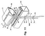
- FIG. 11is a fragmentary, perspective view illustrating a second embodiment of a utility conduit for routing utility lines from the elevated raceway to a lower level;
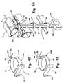
- FIG. 12is a perspective view of a first type of clip utilized to route utility lines along the vertical frame members of the partition of FIG. 1 ;
- FIG. 13is a perspective view of a second embodiment of the clip of FIG. 11 .
- the terms “upper,” “lower,” “right,” “left,” “rear,” “front,” “vertical,” “horizontal,” and derivatives thereofshall relate to the invention as oriented in FIG. 1 .
- the inventionmay assume various alternative orientations and step sequences, except where expressly specified to the contrary.
- the specific devices and processes illustrated in the attached drawings and described in the following specificationare simply exemplary embodiments of the inventive concepts defined in the appended claims. Hence, specific dimensions and other physical characteristics relating to the embodiments disclosed herein are not to be considered as limiting, unless the claims expressly state otherwise.
- FIG. 1illustrates a partition system 1 including an elevated raceway assembly 2 according to the present invention.
- the elevated raceway assembly 2routes utility lines 3 such as power or communications (“data”) lines in a vertically spaced relationship above an upper edge 4 of the partition 1 .
- the elevated raceway assembly 2includes a raceway 5 defining an elongated passageway (see also FIG. 3 ) configured to retain utility lines 3 in a horizontally extending manner.
- the raceway 5is presently utilized to route data lines such as telephone lines, the term “raceway” as used herein incorporates an arrangement capable of routing a wide range of utilities, and is not limited to power and/or data lines.
- the raceway 5is an extruded polymer material.
- a second embodiment 5 AFIG.
- partition system 1may include a first partition panel 10 having a first height, a second partition panel 11 having a second height, and a third partition panel 12 having a third height.
- a first support member 7extends downwardly from the raceway 5 or 5 A, and has a connector such as a bracket 13 spaced apart from the raceway 5 or 5 A a first vertical distance. As described in more detail below, the bracket 13 is configured to attach to a partition panel frame 16 .
- a second support member 8extends downwardly from the raceway 5 or 5 A, and has a connector such as bracket 13 spaced apart from the raceway 5 or 5 A a second vertical distance that is different from the first vertical distance such that the raceway 5 or 5 A is supported at a generally uniform vertical height spaced above the upper edges 4 of the partitions 10 and 11 having different heights.
- each of the support members 7 , 8 , and 9have substantially the same cross-sectional shape, but vary in height.
- the support member 9includes a central web 26 , and a pair of side webs 27 , thus forming an I-beam type cross sectional shape.
- a vertically elongated opening 28 through the central web 26 of support members 7 and 8may receive a sheet 29 ( FIG. 9 ) forming an extension screen.
- Support 9does not include an opening 28 , but otherwise has the same cross sectional shape as supports 7 and 8 .
- the raceway member 5includes a pair of downwardly opening grooves 30 that receive the upper ends 31 of side webs 27 to secure the raceway 5 on the support 9 .
- Raceway 5includes a pair of flexible flaps 34 that can be rotated upwardly to permit insertion of the utility lines 3 into the elongated cavity 6 .
- Raceway member 5is preferably a dual durometer polymer, wherein the lower U-shaped portion 35 is made of a relatively rigid material, and the flaps 34 are made of a relatively flexible material.
- the second embodiment 5 A of the wirewayis made from roll formed steel, and includes a lower or base web 36 , and a pair of side webs 37 that extend therefrom to form an upwardly opening U-shape cross section.
- the upper ends 38 of side webs 37terminate in small U-shaped flanges 39 that receive the upper ends 31 of the side webs 27 .
- the support member 9 Ais substantially the same as the first embodiment 9 of the support, except that the upper edge 32 A is straight, rather than curved, to fit closely against the lower web 36 of the raceway 5 A.
- the supports 9 and 9 Aare both connected to the horizontal row of slots 21 in horizontal frame member 20 by a bracket 13 .
- a first embodiment of bracket 13includes a upper web 40 , side webs 41 , and inwardly extending lower webs 42 that terminate in upwardly extending flanges 43 .
- the flanges 43 and a portion of the lower webs 42are received within the openings 21 in the horizontal frame member 20 .
- the support member 9is then installed on the bracket 13 , with the lower edge 46 of web 26 received between first and second upper protrusions 44 and 45 on upper web 40 of bracket 13 .
- Openings 47 in side webs 41 of bracket 13 , and openings 48 in side web 27 of extension 9receive a conventional threaded fastener or other connector to secure the extension 9 to the bracket 13 .
- the bracket 13may also be utilized with a support member 9 A when a raceway 5 A is utilized.
- a second embodiment 13 A of the bracketincludes a side web 49 , a base web 50 , a pair of spaced apart upwardly extending tabs 51 , and a downwardly extending central tab 52 .
- the tabs 51extend into the openings 21
- the downwardly extending tab 51fits closely against the side surface 53 of horizontal frame member 20 .
- An opening 54receives a fastener to secure the bracket 13 A to the opening 48 through the side web 27 of support member 9 .
- a bracket 13 Ais connected to each of the side webs 27 of the support 9 , such that the support 9 engages the openings 21 on each side of the upper horizontal frame member 20 .
- Either of the embodiments 13 or 13 A of the bracketmay be utilized with either embodiment of the supports 9 or 9 A, or with the supports 7 and 8 of different lengths.
- the supports 7 , 8 , and 9 of various lengthsmay comprise either the first embodiment utilized to support the raceway 5 of FIG. 3 , or the second embodiment of the support utilized to support the second embodiment of the raceway 5 A illustrated in FIG. 4 .
- a sheet 29may be disposed in the elongated vertical slots 28 of the support members, thus providing an additional degree of privacy if required for a particular application.
- the sheet 29may comprise a translucent or frosted polymer material, or may comprise an opaque material as required to provide the desired degree of privacy.
- the sheet 29could be made of virtually any material having the desired characteristics for a given user. Sheet 29 is installed by sliding the sheet 29 into slots 28 .
- a utility conduit assembly 60may be utilized to route utility lines downwardly from the raceway 5 to the height of a worksurface 19 (see also FIG. 1 ), or other convenient height within the workspace.
- An elongated member 61includes an upper end 62 that is received within the groove or slot 30 in the raceway 5 , and a hooked bracket 63 secures the elongated member 61 to the row of openings 21 in the horizontal frame member 20 .
- a plurality of retainers 64have a C-shape, with a pair of opposed grooves 65 that receive the opposite edges 66 of the elongated member 61 to retain the retainer clips 64 .
- the elongated member 61is made of steel, and the retainer clips 64 are made of a flexible polymer material to permit the clips 64 to be flexed open for connection to the elongated member 61 .
- a receptacle 67 for receiving power or communications plugsis secured to the lower end 68 of the elongated member 61 .
- the utility conduit 60may be of varying lengths to permit routing of utility lines to a desired height.
- an optional horizontal cross brace 69includes a pair of hooked brackets that engage the vertical rows of openings 18 to support the horizontal brace 69 .
- the elongated member 61abuts the horizontal brace 69 to prevent rotation of the utility conduit 60 , particularly in applications wherein the frames 16 are not covered by cover panels 22 (see also FIG. 1 ).
- bracket 63 and upper end 62provide sufficient strength to permit use of utility conduit 60 without brace 69 , it is anticipated that brace 69 could be utilized if required for certain applications.
- the cover panels 22are substantially the same as the existing Steelcase AVENIR cover panels, and will therefor not be described in detail herein.
- the elongated member 61may include a downwardly opening J-shaped hook (not shown) that engages the upper ends 38 ( FIG. 4 ) of the second embodiment 5 A of the utility trough.
- a second embodiment 60 A of the utility conduitincludes an elongated rod 71 , and a plurality of clips 72 that retain and route the utility lines 3 .
- Clips 72include a base 73 that slides or clips onto the elongated rod 71 .
- a C-shaped extension 74extends outwardly from the base 73 , forming a hook like structure that permits insertion of the utility lines 3 .
- a bracket 75includes a plurality of extensions 76 that fit tightly into the horizontal row of openings 21 to support the elongated rod 71 .
- a fitting 77 at the upper end 78 of the rod 71includes a flat end portion 79 that is received in the grooves 30 of the raceway 5 to retain the rod 71 .
- the second embodiment 60 A of the utility conduitmay also be supported by a horizontal brace 69 ( FIG. 1 ).
- a polymer clip 80includes a pair of extensions 81 that extend inwardly towards one another.
- the extensions 81are received within the vertical row of openings 18 along a side edge 82 (see also FIG. 1 ) of a partition frame 60 .
- the legs 83 of clip 80may be flexed outwardly to increase the gap 84 at the ends 85 of legs 83 to permit insertion of the utility lines 3 .
- the clip 80permits external routing of the utility lines 3 on the partition panel frames 16 , without requiring a vertical cover or the like.
- a second embodiment 80 A ( FIG. 13 ) of the clipis substantially identical to the first embodiment 80 , except that the legs 83 have an arcuate shape.
- a second embodiment 80 A of the clipis otherwise substantially the same as the first embodiment 80 .
- the elevated raceway 2 of the present inventionpermits routing of utility lines 3 at a constant height, despite changes in the height of the panel below the raceway.
- the utility conduitspermit routing of utility lines downwardly from the elevated raceway, and the horizontal brace 69 supports the utility conduits 60 or 60 A in applications wherein the frame is not covered by cover panels 22 .
- the openings 28 in the raceway support members 8 – 10permit insertion of an extension screen 29 to provide an increased level of privacy if required for a particular application.
Landscapes
- Engineering & Computer Science (AREA)
- Architecture (AREA)
- Civil Engineering (AREA)
- Structural Engineering (AREA)
- Installation Of Indoor Wiring (AREA)
- Bridges Or Land Bridges (AREA)
- Details Of Indoor Wiring (AREA)
Abstract
Description
| Appln. No. | Filing Date | Title | U.S. Pat. No. | Issue Date |
| 09/692,786 | Oct. 20, 2000 | PARTITION PANEL | 6,481,163 | Nov. 19, 2002 |
| 09/693,225 | Oct. 20, 2000 | PARTITION PANEL WITH | 6,533,019 | Mar. 18, 2003 |
| INFILL ARRANGEMENT | ||||
| 09/693,316 | Oct. 20, 2000 | PARTITION SYSTEM WITH | 6,625,935 | Sep. 30, 2003 |
| WORKTOOLS | ||||
| 09/692,796 | Oct. 20, 2000 | TOP CAP AND SCREEN | Abandoned | |
| FOR PARTITIONS | ||||
Claims (28)
Priority Applications (4)
| Application Number | Priority Date | Filing Date | Title |
|---|---|---|---|
| US09/692,663US7210270B1 (en) | 2000-10-20 | 2000-10-20 | Partition system with elevated raceway |
| AU2002224436AAU2002224436A1 (en) | 2000-10-20 | 2001-10-18 | Partition system with elevated raceway |
| PCT/US2001/032541WO2002035669A2 (en) | 2000-10-20 | 2001-10-18 | Partition system with elevated raceway |
| JP2002538540AJP2004530065A (en) | 2000-10-20 | 2001-10-18 | Partition system with elevated raceway |
Applications Claiming Priority (1)
| Application Number | Priority Date | Filing Date | Title |
|---|---|---|---|
| US09/692,663US7210270B1 (en) | 2000-10-20 | 2000-10-20 | Partition system with elevated raceway |
Publications (1)
| Publication Number | Publication Date |
|---|---|
| US7210270B1true US7210270B1 (en) | 2007-05-01 |
Family
ID=24781494
Family Applications (1)
| Application Number | Title | Priority Date | Filing Date |
|---|---|---|---|
| US09/692,663Expired - Fee RelatedUS7210270B1 (en) | 2000-10-20 | 2000-10-20 | Partition system with elevated raceway |
Country Status (4)
| Country | Link |
|---|---|
| US (1) | US7210270B1 (en) |
| JP (1) | JP2004530065A (en) |
| AU (1) | AU2002224436A1 (en) |
| WO (1) | WO2002035669A2 (en) |
Cited By (33)
| Publication number | Priority date | Publication date | Assignee | Title |
|---|---|---|---|---|
| US20050279033A1 (en)* | 2004-06-22 | 2005-12-22 | Mike Faber | Fabricated wall system |
| USD593215S1 (en)* | 2008-02-22 | 2009-05-26 | Julius Blum Gmbh | Partitioning wall |
| USD615129S1 (en)* | 2009-03-25 | 2010-05-04 | Joseph Allen | Combined advertising panels and portion of a shopping cart corral |
| US20100263308A1 (en)* | 2009-04-20 | 2010-10-21 | Olvera Robert E | Systems and Methods for Modular Building Construction with Integrated Utility Service |
| US20100327245A1 (en)* | 2009-06-24 | 2010-12-30 | Starlite Media | Shopping Cart Corral for Displaying One or More Advertisements and Method of Providing Same |
| US8104850B2 (en) | 2007-05-30 | 2012-01-31 | Steelcase Inc. | Furniture storage unit |
| USD653709S1 (en)* | 2009-03-17 | 2012-02-07 | Starlite Media, Llc | Pair of advertising panels affixed to the entry portion of a shopping cart corral |
| US20120073233A1 (en)* | 2010-09-24 | 2012-03-29 | Principle Holdings Limited | Modular walling systems |
| USD663779S1 (en) | 2010-03-16 | 2012-07-17 | Starlite Media, Llc | Pair of advertising panels affixed to the entry portion of a shopping cart corral |
| US8393122B2 (en) | 2002-06-06 | 2013-03-12 | Kimball International, Inc. | Partition system |
| US8549804B2 (en) | 2010-10-21 | 2013-10-08 | Kimball International, Inc. | Office partition electrical system |
| USD695837S1 (en) | 2013-03-13 | 2013-12-17 | Starlite Media, Llc | Combined shopping cart corral with advertising panels |
| USD695835S1 (en) | 2013-03-13 | 2013-12-17 | Starlite Media, Llc | Combined shopping cart corral with center advertising panel |
| USD695836S1 (en) | 2013-03-13 | 2013-12-17 | Starlite Media, Llc | Combined shopping cart corral with front advertising panel |
| USD699789S1 (en) | 2009-03-17 | 2014-02-18 | Starlite Media, Llc | Pair of advertising panels affixed to the entry portion of a shopping cart corral |
| US8984782B1 (en) | 2010-03-16 | 2015-03-24 | Starlite Media, Llc | Shopping cart corrals with at least two advertisement panels arranged in a staggered fashion and method of providing same |
| USD753943S1 (en) | 2011-06-11 | 2016-04-19 | Dirtt Environmental Solutions, Ltd | Modular wall nesting system |
| USD754991S1 (en) | 2011-12-28 | 2016-05-03 | Dirtt Environmental Solutions, Ltd | Modular wall incorporating recessed, extendable furniture |
| US9367859B2 (en) | 2010-03-16 | 2016-06-14 | Starlite Media, Llc | Systems and methods for near field communication enabled shopping cart corrals |
| USD786975S1 (en) | 2015-02-27 | 2017-05-16 | Starlite Media, Llc | Pair of advertising panels with triangular marker for shopping cart corral |
| USD786974S1 (en) | 2015-02-27 | 2017-05-16 | Starlite Media, Llc | Pair of advertising panels with rounded marker for shopping cart corral |
| USD788226S1 (en) | 2015-02-27 | 2017-05-30 | Starlite Media, Llc | Pair of advertising panels with rectangular marker for shopping cart corral |
| US9943165B2 (en) | 2016-02-10 | 2018-04-17 | Dirtt Environmental Solutions, Ltd. | Embedded furniture having retractible legs with lighting |
| USRE46929E1 (en) | 2004-08-17 | 2018-07-03 | Dirtt Environmental Solutions, Ltd | Integrated reconfigurable wall system |
| US20180233890A1 (en)* | 2015-08-06 | 2018-08-16 | Owwi | Expandable room comprising a partition electrically connectable to a wall or a ceiling |
| USD856041S1 (en)* | 2017-12-20 | 2019-08-13 | United Services Automobile Association (Usaa) | Freestanding flower wall panel display |
| US11085184B2 (en) | 2014-02-20 | 2021-08-10 | Dirtt Environmental Solutions Ltd. | Interface for mounting interchangable components |
| US11093087B2 (en) | 2016-06-10 | 2021-08-17 | Dirtt Environmental Solutions Ltd. | Glass substrates with touchscreen technology |
| USRE48722E1 (en) | 2004-08-17 | 2021-09-07 | Dirtt Environmental Solutions Ltd. | Integrated reconfigurable wall system |
| US11240922B2 (en) | 2016-06-10 | 2022-02-01 | Dirtt Environmental Solutions Ltd. | Wall system with electronic device mounting assembly |
| US20220034087A1 (en)* | 2020-07-28 | 2022-02-03 | Kenneth Himmler, SR. | System and method for building a modular based partition |
| US11550178B2 (en) | 2016-07-08 | 2023-01-10 | Dirtt Environmental Solutions Inc. | Low-voltage smart glass |
| US11698502B2 (en)* | 2020-03-09 | 2023-07-11 | Commscope Technologies Llc | Bracket arrangement for cable trough system |
Citations (41)
| Publication number | Priority date | Publication date | Assignee | Title |
|---|---|---|---|---|
| US758088A (en)* | 1903-10-23 | 1904-04-26 | Curtis G Mixer | Frame for holding signs. |
| US1887894A (en)* | 1932-05-23 | 1932-11-15 | Southern Spring Bed Company | Sign holder |
| US2049855A (en)* | 1935-07-30 | 1936-08-04 | Pierre H Meyer | Price card holder |
| US2125747A (en)* | 1937-10-30 | 1938-08-02 | Reflector Hardware Corp | Holder for partitions and the like |
| US2752709A (en)* | 1953-11-09 | 1956-07-03 | Boyd C Gough | Sign holding and attaching clamps |
| US3719000A (en)* | 1970-12-18 | 1973-03-06 | Display Corp Int | Placard holding display assembly |
| US3817396A (en)* | 1972-06-09 | 1974-06-18 | Package Exhibit Programs Inc | Portable display apparatus |
| US4030219A (en)* | 1976-06-01 | 1977-06-21 | Package Exhibit Programs, Inc. | Portable display apparatus |
| US4094561A (en)* | 1977-06-20 | 1978-06-13 | Harter Corporation | Wiring enclosure for desks |
| US4119285A (en)* | 1976-05-04 | 1978-10-10 | Hilti Aktiengesellschaft | Pipe and cable clip |
| US4716698A (en) | 1986-06-06 | 1988-01-05 | Haworth, Inc. | Wall system with split pole for lay-in wiring |
| US4738040A (en)* | 1985-05-17 | 1988-04-19 | Geimuplast Peter Mundt Gmbh. & Co. Kg. | Slide frame and method of inserting a film transparency in a slide frame |
| US4951906A (en)* | 1988-01-11 | 1990-08-28 | Morey Norman E | Sign attachment |
| US5209035A (en) | 1991-01-10 | 1993-05-11 | Steelcase Inc. | Utility panel system |
| US5271585A (en) | 1990-10-01 | 1993-12-21 | Zetena Jr Maurice F | Modular fiber optics raceway permitting flexible installation |
| US5277007A (en) | 1992-05-04 | 1994-01-11 | Teknion Furniture Systems | Office panel with top lay-in passageway |
| US5362923A (en) | 1991-11-27 | 1994-11-08 | Herman Miller, Inc. | System for distributing and managing cabling within a work space |
| US5393021A (en)* | 1994-03-07 | 1995-02-28 | Cablewave Systems | Cable hanger |
| US5606919A (en)* | 1995-06-07 | 1997-03-04 | Haworth, Inc. | Space-dividing fence for power and/or communication distribution |
| US5626926A (en)* | 1994-10-12 | 1997-05-06 | Lin Pac, Inc. | Stand-alone decorative assembly |
| US5675949A (en)* | 1993-05-18 | 1997-10-14 | Steelcase Inc. | Utility distribution system for open office plans and the like |
| US5743052A (en) | 1994-03-01 | 1998-04-28 | Mayhall; Michael W. | Business recovery installation and method for its erection |
| US5831211A (en) | 1996-04-04 | 1998-11-03 | Clifford W. Gartung | Variable-type cable management and distribution system |
| US5986212A (en) | 1997-10-09 | 1999-11-16 | Lhota; Thomas E. | Plastic channel for electrical wiring |
| US6003255A (en)* | 1998-08-11 | 1999-12-21 | Mahoney; Paul | Advertising sign and display |
| US6023896A (en)* | 1998-08-24 | 2000-02-15 | Finish Group Ltd. | Modular partition systems and methods for assembling such systems |
| WO2000021412A1 (en) | 1998-10-13 | 2000-04-20 | Herman Miller, Inc. | Work space management and furniture system |
| US6079173A (en)* | 1997-05-15 | 2000-06-27 | Steelcase Development Inc. | Knock-down portable partition system |
| US6101773A (en)* | 1999-01-13 | 2000-08-15 | Steelcase Inc. | Wire management system |
| US6161347A (en) | 1996-08-05 | 2000-12-19 | Haworth, Inc. | Panel arrangement |
| US6178702B1 (en)* | 1998-04-15 | 2001-01-30 | Steelcase Development Inc. | Flexible light seal for partition systems |
| US6253509B1 (en)* | 1999-08-13 | 2001-07-03 | Teknion Furniture Systems Limited | Workspace partition system |
| US6330773B1 (en) | 1999-04-16 | 2001-12-18 | Steelcase Development Corporation | Stacking bracket for partitions |
| US6341457B1 (en)* | 1996-06-07 | 2002-01-29 | Herman Miller, Inc. | Light seal assembly for a wall panel system |
| US6349516B1 (en)* | 1999-06-04 | 2002-02-26 | Haworth, Inc. | Frame arrangement for a wall panel system |
| US6363663B1 (en)* | 1999-05-11 | 2002-04-02 | Steelcase Development Corporation | Post engaging brackets for partitions |
| US6453826B1 (en)* | 1999-04-30 | 2002-09-24 | Haworth, Inc. | Furniture arrangement having a slidable intermediate table |
| US20020189180A1 (en)* | 2001-06-15 | 2002-12-19 | King Jonathan J. | Panel system |
| US6622976B1 (en)* | 2001-09-18 | 2003-09-23 | Daniel J. Ianello | Cable hanger for installing cables on transmitting tower |
| US6648280B1 (en)* | 1998-11-24 | 2003-11-18 | The Marvel Group, Inc. | Wire harness for modular office furniture |
| US6817147B1 (en)* | 1999-12-30 | 2004-11-16 | Steelcase Development Corporation | Clip for panel trim |
- 2000
- 2000-10-20USUS09/692,663patent/US7210270B1/ennot_activeExpired - Fee Related
- 2001
- 2001-10-18AUAU2002224436Apatent/AU2002224436A1/ennot_activeAbandoned
- 2001-10-18WOPCT/US2001/032541patent/WO2002035669A2/enactiveApplication Filing
- 2001-10-18JPJP2002538540Apatent/JP2004530065A/enactivePending
Patent Citations (44)
| Publication number | Priority date | Publication date | Assignee | Title |
|---|---|---|---|---|
| US758088A (en)* | 1903-10-23 | 1904-04-26 | Curtis G Mixer | Frame for holding signs. |
| US1887894A (en)* | 1932-05-23 | 1932-11-15 | Southern Spring Bed Company | Sign holder |
| US2049855A (en)* | 1935-07-30 | 1936-08-04 | Pierre H Meyer | Price card holder |
| US2125747A (en)* | 1937-10-30 | 1938-08-02 | Reflector Hardware Corp | Holder for partitions and the like |
| US2752709A (en)* | 1953-11-09 | 1956-07-03 | Boyd C Gough | Sign holding and attaching clamps |
| US3719000A (en)* | 1970-12-18 | 1973-03-06 | Display Corp Int | Placard holding display assembly |
| US3817396A (en)* | 1972-06-09 | 1974-06-18 | Package Exhibit Programs Inc | Portable display apparatus |
| US4119285A (en)* | 1976-05-04 | 1978-10-10 | Hilti Aktiengesellschaft | Pipe and cable clip |
| US4030219A (en)* | 1976-06-01 | 1977-06-21 | Package Exhibit Programs, Inc. | Portable display apparatus |
| US4094561A (en)* | 1977-06-20 | 1978-06-13 | Harter Corporation | Wiring enclosure for desks |
| US4738040A (en)* | 1985-05-17 | 1988-04-19 | Geimuplast Peter Mundt Gmbh. & Co. Kg. | Slide frame and method of inserting a film transparency in a slide frame |
| US4716698A (en) | 1986-06-06 | 1988-01-05 | Haworth, Inc. | Wall system with split pole for lay-in wiring |
| US4951906A (en)* | 1988-01-11 | 1990-08-28 | Morey Norman E | Sign attachment |
| US5271585A (en) | 1990-10-01 | 1993-12-21 | Zetena Jr Maurice F | Modular fiber optics raceway permitting flexible installation |
| US5316244A (en) | 1990-10-01 | 1994-05-31 | Zetena Jr Maurice F | Supporting brackets for cable raceways |
| US5209035A (en) | 1991-01-10 | 1993-05-11 | Steelcase Inc. | Utility panel system |
| US20020069601A1 (en)* | 1991-01-10 | 2002-06-13 | Hodges Ronald R. | Utility panel system |
| US5487246A (en)* | 1991-01-10 | 1996-01-30 | Steelcase Inc. | Utility panel system |
| US5362923A (en) | 1991-11-27 | 1994-11-08 | Herman Miller, Inc. | System for distributing and managing cabling within a work space |
| US5277007A (en) | 1992-05-04 | 1994-01-11 | Teknion Furniture Systems | Office panel with top lay-in passageway |
| US5675949A (en)* | 1993-05-18 | 1997-10-14 | Steelcase Inc. | Utility distribution system for open office plans and the like |
| US5743052A (en) | 1994-03-01 | 1998-04-28 | Mayhall; Michael W. | Business recovery installation and method for its erection |
| US5393021A (en)* | 1994-03-07 | 1995-02-28 | Cablewave Systems | Cable hanger |
| US5626926A (en)* | 1994-10-12 | 1997-05-06 | Lin Pac, Inc. | Stand-alone decorative assembly |
| US5606919A (en)* | 1995-06-07 | 1997-03-04 | Haworth, Inc. | Space-dividing fence for power and/or communication distribution |
| US5831211A (en) | 1996-04-04 | 1998-11-03 | Clifford W. Gartung | Variable-type cable management and distribution system |
| US6341457B1 (en)* | 1996-06-07 | 2002-01-29 | Herman Miller, Inc. | Light seal assembly for a wall panel system |
| US6161347A (en) | 1996-08-05 | 2000-12-19 | Haworth, Inc. | Panel arrangement |
| US6079173A (en)* | 1997-05-15 | 2000-06-27 | Steelcase Development Inc. | Knock-down portable partition system |
| US5986212A (en) | 1997-10-09 | 1999-11-16 | Lhota; Thomas E. | Plastic channel for electrical wiring |
| US6178702B1 (en)* | 1998-04-15 | 2001-01-30 | Steelcase Development Inc. | Flexible light seal for partition systems |
| US6003255A (en)* | 1998-08-11 | 1999-12-21 | Mahoney; Paul | Advertising sign and display |
| US6023896A (en)* | 1998-08-24 | 2000-02-15 | Finish Group Ltd. | Modular partition systems and methods for assembling such systems |
| WO2000021412A1 (en) | 1998-10-13 | 2000-04-20 | Herman Miller, Inc. | Work space management and furniture system |
| US6648280B1 (en)* | 1998-11-24 | 2003-11-18 | The Marvel Group, Inc. | Wire harness for modular office furniture |
| US6101773A (en)* | 1999-01-13 | 2000-08-15 | Steelcase Inc. | Wire management system |
| US6330773B1 (en) | 1999-04-16 | 2001-12-18 | Steelcase Development Corporation | Stacking bracket for partitions |
| US6453826B1 (en)* | 1999-04-30 | 2002-09-24 | Haworth, Inc. | Furniture arrangement having a slidable intermediate table |
| US6363663B1 (en)* | 1999-05-11 | 2002-04-02 | Steelcase Development Corporation | Post engaging brackets for partitions |
| US6349516B1 (en)* | 1999-06-04 | 2002-02-26 | Haworth, Inc. | Frame arrangement for a wall panel system |
| US6253509B1 (en)* | 1999-08-13 | 2001-07-03 | Teknion Furniture Systems Limited | Workspace partition system |
| US6817147B1 (en)* | 1999-12-30 | 2004-11-16 | Steelcase Development Corporation | Clip for panel trim |
| US20020189180A1 (en)* | 2001-06-15 | 2002-12-19 | King Jonathan J. | Panel system |
| US6622976B1 (en)* | 2001-09-18 | 2003-09-23 | Daniel J. Ianello | Cable hanger for installing cables on transmitting tower |
Cited By (54)
| Publication number | Priority date | Publication date | Assignee | Title |
|---|---|---|---|---|
| US8393122B2 (en) | 2002-06-06 | 2013-03-12 | Kimball International, Inc. | Partition system |
| US7469512B2 (en)* | 2004-06-22 | 2008-12-30 | Board of Regents of the University of Nebraska by and behalf of University of Nebraska Medical Center | Fabricated wall system |
| US20050279033A1 (en)* | 2004-06-22 | 2005-12-22 | Mike Faber | Fabricated wall system |
| USRE48722E1 (en) | 2004-08-17 | 2021-09-07 | Dirtt Environmental Solutions Ltd. | Integrated reconfigurable wall system |
| USRE46929E1 (en) | 2004-08-17 | 2018-07-03 | Dirtt Environmental Solutions, Ltd | Integrated reconfigurable wall system |
| USRE47132E1 (en) | 2004-08-17 | 2018-11-20 | Dirtt Environmental Solutions, Ltd | Integrated reconfigurable wall system |
| USRE47693E1 (en) | 2004-08-17 | 2019-11-05 | Dirtt Environmental Solutions, Ltd. | Integrated reconfigurable wall system |
| US8104850B2 (en) | 2007-05-30 | 2012-01-31 | Steelcase Inc. | Furniture storage unit |
| USD593214S1 (en)* | 2008-02-22 | 2009-05-26 | Julius Blum Gmbh | Partitioning wall |
| USD593215S1 (en)* | 2008-02-22 | 2009-05-26 | Julius Blum Gmbh | Partitioning wall |
| USD699789S1 (en) | 2009-03-17 | 2014-02-18 | Starlite Media, Llc | Pair of advertising panels affixed to the entry portion of a shopping cart corral |
| USD653709S1 (en)* | 2009-03-17 | 2012-02-07 | Starlite Media, Llc | Pair of advertising panels affixed to the entry portion of a shopping cart corral |
| USD667504S1 (en) | 2009-03-17 | 2012-09-18 | Starlite Media, Llc | Shopping cart corral having an entry portion to which advertisements are affixed |
| USD725287S1 (en) | 2009-03-17 | 2015-03-24 | Starlite Media, Llc | Shopping cart corral having an entry portion to which advertisements are affixed |
| USD620531S1 (en)* | 2009-03-25 | 2010-07-27 | Joseph Allen | Combined advertising panels and portion of a shopping cart corral |
| USD615129S1 (en)* | 2009-03-25 | 2010-05-04 | Joseph Allen | Combined advertising panels and portion of a shopping cart corral |
| US20100263308A1 (en)* | 2009-04-20 | 2010-10-21 | Olvera Robert E | Systems and Methods for Modular Building Construction with Integrated Utility Service |
| US9138081B1 (en) | 2009-06-24 | 2015-09-22 | Starlite Medite, LLC | Shopping cart corral for displaying one or more advertisements and method of providing same |
| US8424690B2 (en) | 2009-06-24 | 2013-04-23 | Starlite Media, Llc | Shopping cart corral for displaying one or more advertisements and method of providing same |
| US20100327245A1 (en)* | 2009-06-24 | 2010-12-30 | Starlite Media | Shopping Cart Corral for Displaying One or More Advertisements and Method of Providing Same |
| US8205757B2 (en) | 2009-06-24 | 2012-06-26 | Starlite Media, Llc | Shopping cart corral for displaying one or more advertisements and method of providing same |
| US9301628B1 (en) | 2009-06-24 | 2016-04-05 | Starlite Media, Llc | Shopping cart corral for displaying one or more advertisements and method of providing same |
| US8820542B2 (en) | 2009-06-24 | 2014-09-02 | Starlite Media, Llc | Shopping cart corral for displaying one or more advertisements and method of providing same |
| US8984782B1 (en) | 2010-03-16 | 2015-03-24 | Starlite Media, Llc | Shopping cart corrals with at least two advertisement panels arranged in a staggered fashion and method of providing same |
| US9675188B1 (en) | 2010-03-16 | 2017-06-13 | Starlite Media, Llc | Shopping cart corrals with at least two advertisement panels arranged in a staggered fashion and method of providing same |
| USD703271S1 (en) | 2010-03-16 | 2014-04-22 | Starlite Media, Llc | Pair of advertising panels affixed to the entry portion of a shopping cart corral |
| US9301627B1 (en) | 2010-03-16 | 2016-04-05 | Starlite Media, Llc | Shopping cart corrals with at least two advertisement panels arranged in a staggered fashion and method of providing same |
| USD756461S1 (en) | 2010-03-16 | 2016-05-17 | Starlite Media, Llc | Pair of advertising panels affixed to the entry portion of a shopping cart corral |
| US9367859B2 (en) | 2010-03-16 | 2016-06-14 | Starlite Media, Llc | Systems and methods for near field communication enabled shopping cart corrals |
| USD663779S1 (en) | 2010-03-16 | 2012-07-17 | Starlite Media, Llc | Pair of advertising panels affixed to the entry portion of a shopping cart corral |
| US20150020470A1 (en)* | 2010-09-24 | 2015-01-22 | Principle Holdings Limited | Modular walling systems |
| US20120073233A1 (en)* | 2010-09-24 | 2012-03-29 | Principle Holdings Limited | Modular walling systems |
| US8549804B2 (en) | 2010-10-21 | 2013-10-08 | Kimball International, Inc. | Office partition electrical system |
| USD753943S1 (en) | 2011-06-11 | 2016-04-19 | Dirtt Environmental Solutions, Ltd | Modular wall nesting system |
| US9347218B2 (en) | 2011-06-11 | 2016-05-24 | Dirtt Environmental Solutions, Ltd. | Modular wall nesting system |
| US10920418B2 (en) | 2011-12-28 | 2021-02-16 | Dirtt Environmental Solutions, Ltd | Modular walls incorporating recessed, extendable furniture |
| USD754991S1 (en) | 2011-12-28 | 2016-05-03 | Dirtt Environmental Solutions, Ltd | Modular wall incorporating recessed, extendable furniture |
| USD695836S1 (en) | 2013-03-13 | 2013-12-17 | Starlite Media, Llc | Combined shopping cart corral with front advertising panel |
| USD695837S1 (en) | 2013-03-13 | 2013-12-17 | Starlite Media, Llc | Combined shopping cart corral with advertising panels |
| USD695835S1 (en) | 2013-03-13 | 2013-12-17 | Starlite Media, Llc | Combined shopping cart corral with center advertising panel |
| US11085184B2 (en) | 2014-02-20 | 2021-08-10 | Dirtt Environmental Solutions Ltd. | Interface for mounting interchangable components |
| USD786974S1 (en) | 2015-02-27 | 2017-05-16 | Starlite Media, Llc | Pair of advertising panels with rounded marker for shopping cart corral |
| USD786975S1 (en) | 2015-02-27 | 2017-05-16 | Starlite Media, Llc | Pair of advertising panels with triangular marker for shopping cart corral |
| USD788226S1 (en) | 2015-02-27 | 2017-05-30 | Starlite Media, Llc | Pair of advertising panels with rectangular marker for shopping cart corral |
| US20180233890A1 (en)* | 2015-08-06 | 2018-08-16 | Owwi | Expandable room comprising a partition electrically connectable to a wall or a ceiling |
| US10058170B2 (en) | 2016-02-10 | 2018-08-28 | Dirtt Environmental Solutions, Ltd | Modular walls with embedded furniture and opposing feature |
| US9943165B2 (en) | 2016-02-10 | 2018-04-17 | Dirtt Environmental Solutions, Ltd. | Embedded furniture having retractible legs with lighting |
| US11093087B2 (en) | 2016-06-10 | 2021-08-17 | Dirtt Environmental Solutions Ltd. | Glass substrates with touchscreen technology |
| US11240922B2 (en) | 2016-06-10 | 2022-02-01 | Dirtt Environmental Solutions Ltd. | Wall system with electronic device mounting assembly |
| US11550178B2 (en) | 2016-07-08 | 2023-01-10 | Dirtt Environmental Solutions Inc. | Low-voltage smart glass |
| USD856041S1 (en)* | 2017-12-20 | 2019-08-13 | United Services Automobile Association (Usaa) | Freestanding flower wall panel display |
| US11698502B2 (en)* | 2020-03-09 | 2023-07-11 | Commscope Technologies Llc | Bracket arrangement for cable trough system |
| US20220034087A1 (en)* | 2020-07-28 | 2022-02-03 | Kenneth Himmler, SR. | System and method for building a modular based partition |
| US11952772B2 (en)* | 2020-07-28 | 2024-04-09 | Kenneth Himmler, SR. | System and method for building a modular based partition |
Also Published As
| Publication number | Publication date |
|---|---|
| JP2004530065A (en) | 2004-09-30 |
| WO2002035669A3 (en) | 2003-03-06 |
| WO2002035669A2 (en) | 2002-05-02 |
| AU2002224436A1 (en) | 2002-05-06 |
Similar Documents
| Publication | Publication Date | Title |
|---|---|---|
| US7210270B1 (en) | Partition system with elevated raceway | |
| US6591563B2 (en) | Panel system | |
| US5483776A (en) | Utility floor construction | |
| US5768840A (en) | Integrated utility distribution and panel system | |
| US5918433A (en) | Lay-in wireways for a space divider system | |
| US6128877A (en) | Variable width end panel | |
| US6003273A (en) | Utilities infeed panel | |
| US6430882B1 (en) | Floor mounted utility post | |
| US6533019B1 (en) | Partition panel with infill arrangement | |
| US5899025A (en) | Furniture system (pathways-spaceframe) | |
| US5152698A (en) | Floor track system for office furniture and the like | |
| US5784843A (en) | Integrated prefabricated furniture system for fitting-out open plan building space | |
| US6047508A (en) | Wall panel partition system | |
| EP0617178B1 (en) | Wall panel system | |
| US6625935B1 (en) | Partition system with worktools | |
| US6408579B1 (en) | Thin panel beam | |
| EP0998612A1 (en) | Knock-down portable partition system | |
| US6082840A (en) | Freestanding furniture system | |
| US5116235A (en) | Power panel structure | |
| US6481163B1 (en) | Partition panel | |
| US6351917B1 (en) | Stacking connector for partitions | |
| US5943833A (en) | In-floor utility outlet | |
| US5129835A (en) | Power panel structure | |
| EP1210756B1 (en) | A support structure | |
| AU707034B2 (en) | Utility distribution system for open office plans and the like |
Legal Events
| Date | Code | Title | Description |
|---|---|---|---|
| AS | Assignment | Owner name:STEELCASE DEVELOPMENT INC., MICHIGAN Free format text:ASSIGNMENT OF ASSIGNORS INTEREST;ASSIGNORS:KING, JONATHAN J.;RUITER, JOEL T.;DEKKER, DAVID J.;AND OTHERS;REEL/FRAME:011630/0374 Effective date:20010305 | |
| AS | Assignment | Owner name:STEELCASE DEVELOPMENT CORPORATION, MICHIGAN Free format text:CHANGE OF NAME;ASSIGNOR:STEELCASE DEVELOPMENT INC.;REEL/FRAME:012623/0029 Effective date:20010417 | |
| STCF | Information on status: patent grant | Free format text:PATENTED CASE | |
| AS | Assignment | Owner name:STEELCASE INC., MICHIGAN Free format text:MERGER;ASSIGNOR:STEELCASE DEVELOPMENT CORPORATION;REEL/FRAME:020353/0054 Effective date:20071017 | |
| FEPP | Fee payment procedure | Free format text:PAYOR NUMBER ASSIGNED (ORIGINAL EVENT CODE: ASPN); ENTITY STATUS OF PATENT OWNER: LARGE ENTITY | |
| CC | Certificate of correction | ||
| FPAY | Fee payment | Year of fee payment:4 | |
| FPAY | Fee payment | Year of fee payment:8 | |
| FEPP | Fee payment procedure | Free format text:MAINTENANCE FEE REMINDER MAILED (ORIGINAL EVENT CODE: REM.); ENTITY STATUS OF PATENT OWNER: LARGE ENTITY | |
| LAPS | Lapse for failure to pay maintenance fees | Free format text:PATENT EXPIRED FOR FAILURE TO PAY MAINTENANCE FEES (ORIGINAL EVENT CODE: EXP.); ENTITY STATUS OF PATENT OWNER: LARGE ENTITY | |
| STCH | Information on status: patent discontinuation | Free format text:PATENT EXPIRED DUE TO NONPAYMENT OF MAINTENANCE FEES UNDER 37 CFR 1.362 | |
| FP | Lapsed due to failure to pay maintenance fee | Effective date:20190501 |