US7209776B2 - Method of determining the position of the articular point of a joint - Google Patents
Method of determining the position of the articular point of a jointDownload PDFInfo
- Publication number
- US7209776B2 US7209776B2US10/308,622US30862202AUS7209776B2US 7209776 B2US7209776 B2US 7209776B2US 30862202 AUS30862202 AUS 30862202AUS 7209776 B2US7209776 B2US 7209776B2
- Authority
- US
- United States
- Prior art keywords
- point
- articular
- joint
- tibia
- articular point
- Prior art date
- Legal status (The legal status is an assumption and is not a legal conclusion. Google has not performed a legal analysis and makes no representation as to the accuracy of the status listed.)
- Expired - Fee Related, expires
Links
Images


Classifications
- A—HUMAN NECESSITIES
- A61—MEDICAL OR VETERINARY SCIENCE; HYGIENE
- A61B—DIAGNOSIS; SURGERY; IDENTIFICATION
- A61B5/00—Measuring for diagnostic purposes; Identification of persons
- A61B5/45—For evaluating or diagnosing the musculoskeletal system or teeth
- A61B5/4528—Joints
- A—HUMAN NECESSITIES
- A61—MEDICAL OR VETERINARY SCIENCE; HYGIENE
- A61B—DIAGNOSIS; SURGERY; IDENTIFICATION
- A61B34/00—Computer-aided surgery; Manipulators or robots specially adapted for use in surgery
- A61B34/20—Surgical navigation systems; Devices for tracking or guiding surgical instruments, e.g. for frameless stereotaxis
- A—HUMAN NECESSITIES
- A61—MEDICAL OR VETERINARY SCIENCE; HYGIENE
- A61B—DIAGNOSIS; SURGERY; IDENTIFICATION
- A61B5/00—Measuring for diagnostic purposes; Identification of persons
- A61B5/103—Measuring devices for testing the shape, pattern, colour, size or movement of the body or parts thereof, for diagnostic purposes
- A—HUMAN NECESSITIES
- A61—MEDICAL OR VETERINARY SCIENCE; HYGIENE
- A61B—DIAGNOSIS; SURGERY; IDENTIFICATION
- A61B34/00—Computer-aided surgery; Manipulators or robots specially adapted for use in surgery
- A61B34/10—Computer-aided planning, simulation or modelling of surgical operations
- A61B2034/101—Computer-aided simulation of surgical operations
- A61B2034/105—Modelling of the patient, e.g. for ligaments or bones
- A—HUMAN NECESSITIES
- A61—MEDICAL OR VETERINARY SCIENCE; HYGIENE
- A61B—DIAGNOSIS; SURGERY; IDENTIFICATION
- A61B34/00—Computer-aided surgery; Manipulators or robots specially adapted for use in surgery
- A61B34/20—Surgical navigation systems; Devices for tracking or guiding surgical instruments, e.g. for frameless stereotaxis
- A61B2034/2046—Tracking techniques
- A61B2034/2055—Optical tracking systems
- A—HUMAN NECESSITIES
- A61—MEDICAL OR VETERINARY SCIENCE; HYGIENE
- A61B—DIAGNOSIS; SURGERY; IDENTIFICATION
- A61B34/00—Computer-aided surgery; Manipulators or robots specially adapted for use in surgery
- A61B34/20—Surgical navigation systems; Devices for tracking or guiding surgical instruments, e.g. for frameless stereotaxis
- A61B2034/2068—Surgical navigation systems; Devices for tracking or guiding surgical instruments, e.g. for frameless stereotaxis using pointers, e.g. pointers having reference marks for determining coordinates of body points
- A—HUMAN NECESSITIES
- A61—MEDICAL OR VETERINARY SCIENCE; HYGIENE
- A61B—DIAGNOSIS; SURGERY; IDENTIFICATION
- A61B34/00—Computer-aided surgery; Manipulators or robots specially adapted for use in surgery
- A61B34/20—Surgical navigation systems; Devices for tracking or guiding surgical instruments, e.g. for frameless stereotaxis
- A61B2034/2072—Reference field transducer attached to an instrument or patient
- A—HUMAN NECESSITIES
- A61—MEDICAL OR VETERINARY SCIENCE; HYGIENE
- A61B—DIAGNOSIS; SURGERY; IDENTIFICATION
- A61B90/00—Instruments, implements or accessories specially adapted for surgery or diagnosis and not covered by any of the groups A61B1/00 - A61B50/00, e.g. for luxation treatment or for protecting wound edges
- A61B90/39—Markers, e.g. radio-opaque or breast lesions markers
- A61B2090/3937—Visible markers
- A61B2090/3945—Active visible markers, e.g. light emitting diodes
- A—HUMAN NECESSITIES
- A61—MEDICAL OR VETERINARY SCIENCE; HYGIENE
- A61B—DIAGNOSIS; SURGERY; IDENTIFICATION
- A61B5/00—Measuring for diagnostic purposes; Identification of persons
- A61B5/68—Arrangements of detecting, measuring or recording means, e.g. sensors, in relation to patient
- A61B5/6801—Arrangements of detecting, measuring or recording means, e.g. sensors, in relation to patient specially adapted to be attached to or worn on the body surface
- A61B5/6813—Specially adapted to be attached to a specific body part
- A61B5/6828—Leg
- A—HUMAN NECESSITIES
- A61—MEDICAL OR VETERINARY SCIENCE; HYGIENE
- A61B—DIAGNOSIS; SURGERY; IDENTIFICATION
- A61B5/00—Measuring for diagnostic purposes; Identification of persons
- A61B5/68—Arrangements of detecting, measuring or recording means, e.g. sensors, in relation to patient
- A61B5/6801—Arrangements of detecting, measuring or recording means, e.g. sensors, in relation to patient specially adapted to be attached to or worn on the body surface
- A61B5/683—Means for maintaining contact with the body
- A61B5/6831—Straps, bands or harnesses
Definitions
- the inventionconcerns a method for the preoperative determination of the position of the articular point of a joint and specifically a knee joint.
- knee deformitiessuch as genu valgum (knock knee) and genu varum (bowleg) by osteotomy
- the articular pointrepresents an imaginary joint center about which the bones connected at the joint rotate. More precision in the knowledge of the articular point of a joint results in longer lasting replacement joints and more effective correction of deformities.
- markers attached to bones on opposite sides of the joint connecting the bonesare observable by a stereoscopic camera system connected to a data processing system such as a computer that can record the positions of the markers in space and, using software, calculate the kinematic motion of the bones, as well as other mathematical parameters and relationships.
- the markers attached to the bonesestablish a coordinate reference system relative to each bone. Additional camera observable markers are freely moveable and may be used to palpate (touch) specific landmarks on the bones in order to ascertain the position of the landmarks in the coordinate reference systems of the bones.
- the positions of such landmarksare used by the data processing system software, along with the relative motion of the bones connected at the joint of interest, to calculate the geometric and kinematic relationships needed to guide the orthopaedic surgery. Included among these parameters are articular points or joint centers.
- Present methods for determining the position of articular pointsrequire that the knee joint be surgically opened to provide access to the anatomical center of the knee (a landmark point on the femur) so that this point may be palpated by a movable marker to establish its precise location in space relative to the femur coordinate reference system defined by the marker attached to the femur.
- the data processing system softwarecan calculate a relatively accurate position of the knee center in the femur and tibia coordinate systems. The position of the knee center is then used to provide further information directing the placement of endoprostheses or guiding the bone cutting in an osteotomy.
- the inventionconcerns a method for determining the position of an articular point of a central joint between two substantially rigid bodies, the central joint being located between first and second outer joints located at the ends of the first and second rigid bodies distal to the central joint.
- the steps of the methodinclude identifying the position of a first point on the first rigid body located substantially at the central joint.
- the position of a first articular point of the first rigid body at the first outer jointis determined.
- a first axis between the first articular point and the first point previously determinedis defined.
- the respective positions of a second and a third point on the first rigid body on opposite sides of the central jointare identified.
- a plane, substantially perpendicular to the first axis and at substantially equal respective rectangular distances to the second and third pointsis defined.
- the intersection of the plane and the first axisis used as an initial estimate of the articular point of the central joint.
- the position of a second articular point of the second rigid body at the second outer jointis determined.
- a region in the plane having a predetermined sizeis identified, the region including the initial estimate of the articular point of the central joint as well as other points.
- the second articular pointis then moved relatively to the first rigid body by rotating the second rigid body about the central joint.
- a multiplicity of different positions of the second articular pointare identified during the rotation of the second rigid body.
- One point among a multiplicity of points within the regionis identified for which the position is substantially invariant for each of the positions of the second articular point, the one point being the articular point of the central joint.
- the method according to the inventionis specifically applicable to determining the position of the articular point of the knee joint (the knee center) between the femur and the tibia.
- Important landmarks on the knee joint for determining the articular point positioninclude the patella (knee cap) and the medial and lateral epicondyles (the eminences of the femur above the knee joint).
- the method of determining the position of the knee articular point according to the inventioncomprises identifying the position of the patella and determining the position of the articular point of the femur at the hip joint. This information is then used to define a femoral axis that extends between the femur articular point and the patella.
- a planeis defined that is substantially perpendicular to the femoral axis and at substantially equal respective rectangular distances to the positions of the medial and lateral epicondyles.
- the intersection of the plane and the femoral axisis the initial estimate of the articular point of the knee joint.
- a region in the plane having a predetermined sizeis defined.
- the regionincludes the initial estimate of the articular point position of the knee joint and is preferably a circle centered on this point.
- the position of an articular point of the tibia at the ankle jointis then defined and this point is moved relatively to the femur by rotating the tibia about the knee joint while recording multiple positions of the tibia articular point during the rotation.
- the one point within the aforementioned region containing the knee articular pointis identified as the knee articular point whose position is substantially invariant for each of the positions of the tibia articular point.
- the substantially invariant pointis defined by a point within the region having the smallest standard deviation of distance between that point and the tibia articular point for all of the recorded positions of the tibia articular point.
- the step of determining the position of the femur articular pointcomprises the steps of moving the patella by rotating the femur about the hip joint, identifying a plurality of positions of the patella during the motion of the patella about the hip joint and then determining mathematically a common point at the hip joint having substantially the same distance to all of the positions of the patella.
- the common pointis the femur articular point.
- the step of determining the position of the tibia articular point at the anklecomprises the steps of identifying the respective positions of medial and lateral malleoli (protuberances) on opposite sides of the ankle joint and the position of an anterior point of the ankle located in the sagittal plane of the tibia. Using this positional information, a first line between the medial and lateral malleoli is defined and a second line is projected from the anterior point to perpendicularly intersect the first line at an intersection point. The tibia articular point is determined as the intersection point of these two lines.
- FIG. 1is a perspective view of an apparatus used to perform the method of joint articular point determination according to the invention
- FIG. 2is a schematic diagram illustrating various landmarks, bones and mathematical constructs important to determining the knee articular point by the method according to the invention.
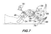
- FIGS. 3–7are elevational views of a leg showing the skeletal structure and illustrating various steps of the method according to the invention.
- FIG. 1illustrates a type of orthopaedic surgical navigation device 10 preferably used to execute the steps of the method of determining the position of the knee articular point according to the invention, it being understood that the method is not limited to any particular device or any particular joint.
- Navigation device 10comprises a stereoscopic sensor system 12 having sensors such as cameras 14 and 16 separated from one another so as to view markers 18 and 20 from different locations, thus allowing the positions of the markers in space to be deduced by techniques such as triangulation based upon comparison of the arrival times of signals from the markers at the different cameras.
- the cameras 14 and 16are sensitive to infrared radiation so as to be usable in ambient visible light.
- the cameras 14 and 16generate signals describing the detected positions of markers 18 and 20 , the signals being fed to a data processing system 22 , preferably comprising a microprocessor with resident software.
- the softwareis written to understand the camera signals and identify the positions of the markers which can then be stored and mathematically manipulated as needed to calculate or deduce further information.
- Information from the softwareis communicated to a user of the system by means of a computer monitor 24 , and the user communicates with the software by means of a keyboard 26 and foot pedals 27 .
- Markers 18 and 20are attachable to the leg 28 of a patient on each side of the knee joint 30 , the articular point of which is to be determined.
- One marker, 18is attached to the upper leg portion 32 which includes the femur 34
- the other marker, 20is attached to the lower leg portion 36 which includes the tibia 38 .
- the markersare preferably attached by means of respective harnesses 40 that prevent each marker from shifting in position on the leg once attached. Harnesses 40 allow the markers to be attached without the use of invasive surgery, thus fulfilling one of the objects of the invention.
- the markersmay also be attached directly to the femur and tibia using bone screws if the bone is surgically exposed.
- the markersbe securely attached to the leg portions so that they always indicate the true locations of the leg portions and not a shift in the marker location relative to the leg. This ensures that any calculations based upon the locations of the markers will be meaningful with respect to the actual leg locations.
- a movable marker 42is not attached to any part of the leg but is variably positionable at any point along the leg.
- Marker 42is attached to a pointer 44 , having a tip 46 .
- the position of the tip 46 relative to the marker 42is known to the software so that positioning the tip 46 at a landmark on the leg 28 (known as “palpating” the landmark) allows the software to precisely identify the position of the landmark relative to the position of the fixed markers 18 and 20 .
- Such relative positional informationis useful for calculating parameters needed to determine the position of the knee articular point as described below.
- Markers 18 , 20 and 42emit infrared radiation visible to the cameras 14 and 16 allowing them to see and track the relative positions and motions of the bodies to which the markers 18 and 20 are attached or that marker 42 is palpating.
- the markersmay have active emitters that generate their own infrared radiation, or passive emitters that reflect infrared radiation from an infrared radiation source associated with the navigation device 10 .
- the locations of the markers 18 and 20are identified to the software of the data processing system 22 by the sensor system 12 .
- the marker locationsestablish frames of reference 48 and 50 on the femur 34 and tibia 38 respectively.
- the locations of landmarks on the leg 28 as well as the relative motion of the landmarks and the relative motion of the femur and tibiamay be identified within the frames of reference.
- a method of determining the position of the articular point of the knee joint(also called the “knee center”) is described below.
- the methodis not limited to the knee joint but may be used on any joint connecting two rigid bodies.
- the method according to the inventionfirst requires that marker 18 be attached to the upper leg portion 32 which includes the femur 34 .
- Marker 20is attached to lower leg portion 36 which includes the tibia 38 .
- markers 18 and 20are viewed by cameras 14 and 16 and defined to the software of the data processing system 22 as being attached to the femur and tibia respectively.
- the softwarecontrols the infrared emissions from each marker via communication cables 18 a, 20 a and 42 a associated with each marker.
- the softwarecan distinguish between the markers by turning them on one at a time.
- Foot pedals 27may be used to communicate interactively in response to the software to indicate that the markers are in place. With the markers 18 and 20 in position as shown in FIG. 1 , foot pedal 27 is pressed in response to a prompting command from the software displayed on the monitor 24 to indicate that the markers are in position and ready.
- the softwarethen activates the markers 18 and 20 which emit infrared signals that are read by the cameras 14 and 16 .
- the camerasidentify the marker locations in space and transmit the information to the software which records their location and mathematically establishes coordinate reference frames 48 and 50 shown in FIG. 3 for the femur and the tibia.
- the position of the patella 52is identified by palpating (touching) the patella with the tip 46 of pointer 44 .
- the movable marker 42 attached to pointer 44is viewed by the cameras 14 and 16 and the position of the patella 52 is identified to the software and thus known relative to both the femur and tibia reference frames 48 and 50 .
- Marker 42may be identified to the software interactively by holding the pointer 44 stationary with its tip 46 on the patella 52 and marker 42 visible to the cameras 14 and 16 and then pressing the foot pedal 27 in response to a prompting command requesting input of the patella location, the command being visible on the monitor 24 .
- the softwareactivates the markers 18 , 20 and 42 in sequence, their infrared emissions are viewed by the cameras 14 and 16 and the software is able to distinguish between the three markers and identify and record their relative locations upon receipt of the information from the cameras.
- the femur articular point 54may be determined by moving the femur 34 about the hip joint 56 as illustrated in dashed line in FIG. 4 in response to a prompting command on the monitor 24 .
- Cameras 14 and 16observe the motion of marker 18 and signal a number of discrete positions of the marker to the software.
- the softwarecalculates the positions of the patella 52 from the positions of marker 18 observed by the cameras during the femur motion.
- the softwareknows that the positions the patella may take all lie on a sphere centered at the articular point of the hip joint.
- the softwarecan calculate the femur articular point 54 in the femur reference frame 48 , the articular point 54 being a common point at the hip joint that has substantially the same distance to all of the positions of the patella 52 .
- the femoral axis 58can be defined. As shown schematically in FIG. 2 , the femoral axis 58 is an imaginary line extending between the femur articular point 54 (i.e., the center of the hip joint) and the position of the patella 52 and is defined mathematically by the software.
- the femoral axis 58does not necessarily coincide with the femur 34 and is used in conjunction with the positions of the medial and lateral epicondyles 60 and 62 respectively, to determine an initial estimate of the knee articular point as described below.
- the epicondylesare eminences that protrude from either side of the femur 34 above the knee joint 30 .
- the positions of the medial and lateral epicondyles 60 and 62 respectivelyare identified by palpating each with the tip 46 of pointer 44 and allowing the movable marker 42 to be observed by the cameras 14 and 16 .
- each epicondyleis palpated, its respective position is identified to the software, again conveniently by responding to interactive prompts on the monitor 24 , the user positioning the pointer 44 appropriately in response to a command and pressing the pedal 27 .
- the softwaremathematically defines a plane 64 perpendicular to the femoral axis 58 .
- the plane 64is located along the femoral axis where the plane is at substantially equal respective rectangular distances 66 and 68 to the positions of the medial and lateral epicondyles 60 and 62 .
- the point of intersection 70 between the plane 64 and the femoral axis 58is the initial estimate of the knee articular point.
- a region 72 in the plane 64is defined that includes the estimate point.
- the region 72is a circle of 1 cm diameter centered on the initial estimate point 70 .
- Region 72contains candidate points for the knee articular point, one of which will be selected mathematically, preferably using statistical methods as described below.
- the position of the articular point 74 of the tibia at the ankle joint 76is determined with respect to the fixed marker 20 , preferably using the positions of the medial and lateral malleoli 78 and 80 .
- the malleoliare the protuberances on either side of the ankle joint.
- the positions of the medial and lateral malleoli 78 and 80 respectivelyare identified by palpating them with the tip 46 of the pointer 44 attached to the movable marker 42 when prompted by the software.
- the marker 42is observed by the cameras 14 and 16 which signals the respective positional information of the malleoli to the software.
- Actuation of foot pedal 27may be used to effect data capture as with previous palpations.
- the position of an anterior point 82 of the ankle joint 76is identified by palpating the anterior region of the ankle in the sagittal plane of the tibia 38 . Knowing the positions of the malleoli 78 and 80 , the software mathematically defines an imaginary line 84 (see FIG. 2 ) between the medial and lateral malleoli 78 and 80 . Knowing the position of anterior point 82 , the software then mathematically projects another line 86 from the anterior point 82 that intersects line 84 substantially perpendicularly. The point 74 where lines 84 and 86 intersect is defined as the tibia articular point.
- the tibia 38is next rotated about the knee joint 30 through a specified range of motion.
- the tibia 38is initially placed at a substantially right angle to the femur 34 and then rotated in flexure (away from the femur), as shown in dashed line, through an angle between about 10° and about 90°, but preferably between about 10° and about 40°.
- Moving the tibiamoves the tibia articular point 74 through a trajectory 88 relative to the knee joint 30 , the motion being constrained by the nature of the knee joint, which may be approximated as a hinge for angular motion between about 10° and about 40°, and the fact that the articular point is at the end of a rigid body (the tibia 38 ) movable about the hinge joint (the knee 30 ).
- Cameras 14 and 16observe the motion of marker 20 on the tibia 38 relative to the marker 18 on the femur 34 and signal the positions of a multiplicity of points of the marker 20 to the software.
- the softwareknows the position of the tibia articular point 74 in the tibia reference frame 50 (i.e., relatively to the marker 20 ) for all motions of the tibia. Using this information, the software can calculate the corresponding motion of the articular point 74 relative to the points within the region 72 (fixed in the femur reference frame 48 as shown in FIG. 2 ) through the trajectory 88 defined by the constraints of a rigid body (the tibia 38 ) rotating about a hinge joint (the knee joint 30 ) relative to another rigid body (the femur 34 ). The software then uses the positional information of the tibia articular point 74 during its motion through trajectory 88 to choose a point from among the points in the region 72 (see FIG. 2 ) which represents the best estimate of the position of the knee articular point 90 based upon a particular set of criteria.
- the point within region 72 having a position that is substantially invariant for a multiplicity of positions of the tibia articular point along its trajectory 88 about the knee joint 30is selected as the knee center or knee articular point 90 .
- the point in region 72 that has the smallest standard deviation of distance to the tibia articular point 74 for a multiplicity of positions of the tibia articular point 74 along the trajectory 88may be selected as the knee articular point or knee center 90 .
- the accuracy with which the position of the knee articular point 90 is determinedwill be proportional to both the number of positions of the tibia articular point 74 that are measured along the trajectory 88 and the number of points in the region 72 each of these points is compared with. Generally, the more points used the greater the accuracy of the answer. Natural physical limits on the ability of the cameras to accurately measure small differences in position, as well as the accumulation of numerical errors within the mathematical algorithms used by the software will of course limit the accuracy of the answer.
- the method of determining the articular point of a jointprovides a fast procedure for acquiring accurate preoperative information respecting the position of a joint center which does not require surgery and, thus, enables the surgeon to avoid inflicting unnecessary trauma on a patient.
Landscapes
- Health & Medical Sciences (AREA)
- Life Sciences & Earth Sciences (AREA)
- Surgery (AREA)
- Engineering & Computer Science (AREA)
- Medical Informatics (AREA)
- Veterinary Medicine (AREA)
- Public Health (AREA)
- General Health & Medical Sciences (AREA)
- Animal Behavior & Ethology (AREA)
- Molecular Biology (AREA)
- Biomedical Technology (AREA)
- Heart & Thoracic Surgery (AREA)
- Biophysics (AREA)
- Pathology (AREA)
- Physics & Mathematics (AREA)
- Oral & Maxillofacial Surgery (AREA)
- Dentistry (AREA)
- Rheumatology (AREA)
- Orthopedic Medicine & Surgery (AREA)
- Nuclear Medicine, Radiotherapy & Molecular Imaging (AREA)
- Robotics (AREA)
- Measurement Of The Respiration, Hearing Ability, Form, And Blood Characteristics Of Living Organisms (AREA)
- Prostheses (AREA)
- Eye Examination Apparatus (AREA)
- Analysing Materials By The Use Of Radiation (AREA)
- Apparatus For Radiation Diagnosis (AREA)
- Image Processing (AREA)
- Two-Way Televisions, Distribution Of Moving Picture Or The Like (AREA)
- Length Measuring Devices By Optical Means (AREA)
Abstract
Description
Claims (14)
Priority Applications (9)
| Application Number | Priority Date | Filing Date | Title |
|---|---|---|---|
| US10/308,622US7209776B2 (en) | 2002-12-03 | 2002-12-03 | Method of determining the position of the articular point of a joint |
| AU2003292163AAU2003292163A1 (en) | 2002-12-03 | 2003-12-01 | Method of determining the position of the articular point of a joint |
| JP2004556237AJP4331113B2 (en) | 2002-12-03 | 2003-12-01 | How to determine the position of a joint point in a joint |
| PCT/EP2003/013486WO2004049941A1 (en) | 2002-12-03 | 2003-12-01 | Method of determining the position of the articular point of a joint |
| EP03767715AEP1569554B1 (en) | 2002-12-03 | 2003-12-01 | Method of determining the position of the articular point of a joint |
| ES03767715TES2282684T3 (en) | 2002-12-03 | 2003-12-01 | PROCEDURE TO DETERMINE THE POSITION OF THE ARTICULAR POINT OF AN ARTICULATION. |
| DE60312210TDE60312210T2 (en) | 2002-12-03 | 2003-12-01 | METHOD FOR DETERMINING THE MECHANISM POINTS |
| AT03767715TATE355012T1 (en) | 2002-12-03 | 2003-12-01 | METHOD FOR DETERMINING THE JOINT CENTER POINTS |
| US11/507,158US7780677B2 (en) | 2002-12-03 | 2006-08-21 | Method of determining the position of the articular point of a joint |
Applications Claiming Priority (1)
| Application Number | Priority Date | Filing Date | Title |
|---|---|---|---|
| US10/308,622US7209776B2 (en) | 2002-12-03 | 2002-12-03 | Method of determining the position of the articular point of a joint |
Related Child Applications (1)
| Application Number | Title | Priority Date | Filing Date |
|---|---|---|---|
| US11/507,158DivisionUS7780677B2 (en) | 2002-12-03 | 2006-08-21 | Method of determining the position of the articular point of a joint |
Publications (2)
| Publication Number | Publication Date |
|---|---|
| US20040106861A1 US20040106861A1 (en) | 2004-06-03 |
| US7209776B2true US7209776B2 (en) | 2007-04-24 |
Family
ID=32392795
Family Applications (2)
| Application Number | Title | Priority Date | Filing Date |
|---|---|---|---|
| US10/308,622Expired - Fee RelatedUS7209776B2 (en) | 2002-12-03 | 2002-12-03 | Method of determining the position of the articular point of a joint |
| US11/507,158Expired - Fee RelatedUS7780677B2 (en) | 2002-12-03 | 2006-08-21 | Method of determining the position of the articular point of a joint |
Family Applications After (1)
| Application Number | Title | Priority Date | Filing Date |
|---|---|---|---|
| US11/507,158Expired - Fee RelatedUS7780677B2 (en) | 2002-12-03 | 2006-08-21 | Method of determining the position of the articular point of a joint |
Country Status (8)
| Country | Link |
|---|---|
| US (2) | US7209776B2 (en) |
| EP (1) | EP1569554B1 (en) |
| JP (1) | JP4331113B2 (en) |
| AT (1) | ATE355012T1 (en) |
| AU (1) | AU2003292163A1 (en) |
| DE (1) | DE60312210T2 (en) |
| ES (1) | ES2282684T3 (en) |
| WO (1) | WO2004049941A1 (en) |
Cited By (49)
| Publication number | Priority date | Publication date | Assignee | Title |
|---|---|---|---|---|
| US20050021044A1 (en)* | 2003-06-09 | 2005-01-27 | Vitruvian Orthopaedics, Llc | Surgical orientation device and method |
| US20050143676A1 (en)* | 2001-12-11 | 2005-06-30 | De Guise Jacques A. | Method of calibration for the representation of knee kinematics and harness for use therewith |
| US20050182320A1 (en)* | 2002-05-21 | 2005-08-18 | Jan Stifter | Arrangement for ascertaining function-determining geometric parameters of a joint of a vertebrate |
| US20070022252A1 (en)* | 2004-04-27 | 2007-01-25 | Ling Cen | Two-hop cache coherency protocol |
| US20070043375A1 (en)* | 2005-02-17 | 2007-02-22 | Lucas Anissian | Method and system for determining resection guidelines for joint replacement surgical procedures |
| US20070162142A1 (en)* | 2005-06-15 | 2007-07-12 | Vitruvian Orthopaedics, Llc | Knee surgery method and apparatus |
| US20080039716A1 (en)* | 2006-08-11 | 2008-02-14 | Gregor Tuma | Method and system for determining the location of a medical instrument relative to a body structure |
| US20080071195A1 (en)* | 2006-09-18 | 2008-03-20 | Cuellar Alberto D | Non-invasive tracking device and method |
| US20090043556A1 (en)* | 2007-08-07 | 2009-02-12 | Axelson Stuart L | Method of and system for planning a surgery |
| US7559931B2 (en) | 2003-06-09 | 2009-07-14 | OrthAlign, Inc. | Surgical orientation system and method |
| US20090226069A1 (en)* | 2008-03-07 | 2009-09-10 | Inneroptic Technology, Inc. | Systems and methods for displaying guidance data based on updated deformable imaging data |
| US20100045783A1 (en)* | 2001-10-19 | 2010-02-25 | Andrei State | Methods and systems for dynamic virtual convergence and head mountable display using same |
| US20100063509A1 (en)* | 2008-07-24 | 2010-03-11 | OrthAlign, Inc. | Systems and methods for joint replacement |
| US7728868B2 (en) | 2006-08-02 | 2010-06-01 | Inneroptic Technology, Inc. | System and method of providing real-time dynamic imagery of a medical procedure site using multiple modalities |
| US20110043612A1 (en)* | 2009-07-31 | 2011-02-24 | Inneroptic Technology Inc. | Dual-tube stereoscope |
| US20110046483A1 (en)* | 2008-01-24 | 2011-02-24 | Henry Fuchs | Methods, systems, and computer readable media for image guided ablation |
| US20110057930A1 (en)* | 2006-07-26 | 2011-03-10 | Inneroptic Technology Inc. | System and method of using high-speed, high-resolution depth extraction to provide three-dimensional imagery for endoscopy |
| US20110082351A1 (en)* | 2009-10-07 | 2011-04-07 | Inneroptic Technology, Inc. | Representing measurement information during a medical procedure |
| US20110099821A1 (en)* | 2009-11-04 | 2011-05-05 | Accumis Inc. | Image calibration device integrated with optical locater |
| US20110208093A1 (en)* | 2010-01-21 | 2011-08-25 | OrthAlign, Inc. | Systems and methods for joint replacement |
| US20110218543A1 (en)* | 2009-07-24 | 2011-09-08 | OrthAlign, Inc. | Systems and methods for joint replacement |
| US8554307B2 (en) | 2010-04-12 | 2013-10-08 | Inneroptic Technology, Inc. | Image annotation in image-guided medical procedures |
| US8585598B2 (en) | 2009-02-17 | 2013-11-19 | Inneroptic Technology, Inc. | Systems, methods, apparatuses, and computer-readable media for image guided surgery |
| US8641621B2 (en) | 2009-02-17 | 2014-02-04 | Inneroptic Technology, Inc. | Systems, methods, apparatuses, and computer-readable media for image management in image-guided medical procedures |
| US8670816B2 (en) | 2012-01-30 | 2014-03-11 | Inneroptic Technology, Inc. | Multiple medical device guidance |
| US8974468B2 (en) | 2008-09-10 | 2015-03-10 | OrthAlign, Inc. | Hip surgery systems and methods |
| US20150105780A1 (en)* | 2012-03-01 | 2015-04-16 | Ostesys | Method and system for determining the alignment of two bones |
| US9282947B2 (en) | 2009-12-01 | 2016-03-15 | Inneroptic Technology, Inc. | Imager focusing based on intraoperative data |
| US9549742B2 (en) | 2012-05-18 | 2017-01-24 | OrthAlign, Inc. | Devices and methods for knee arthroplasty |
| US9585725B2 (en) | 2002-03-20 | 2017-03-07 | P Tech, Llc | Robotic arthroplasty system |
| US9588582B2 (en) | 2013-09-17 | 2017-03-07 | Medibotics Llc | Motion recognition clothing (TM) with two different sets of tubes spanning a body joint |
| US9649160B2 (en) | 2012-08-14 | 2017-05-16 | OrthAlign, Inc. | Hip replacement navigation system and method |
| US9675319B1 (en) | 2016-02-17 | 2017-06-13 | Inneroptic Technology, Inc. | Loupe display |
| US9706948B2 (en) | 2010-05-06 | 2017-07-18 | Sachin Bhandari | Inertial sensor based surgical navigation system for knee replacement surgery |
| US9763683B2 (en) | 2001-08-28 | 2017-09-19 | Bonutti Skeletal Innovations Llc | Method for performing surgical procedures using optical cutting guides |
| US9795394B2 (en) | 2000-01-14 | 2017-10-24 | Bonutti Skeletal Innovations Llc | Method for placing implant using robotic system |
| US9901406B2 (en) | 2014-10-02 | 2018-02-27 | Inneroptic Technology, Inc. | Affected region display associated with a medical device |
| US9949700B2 (en) | 2015-07-22 | 2018-04-24 | Inneroptic Technology, Inc. | Medical device approaches |
| US10058393B2 (en) | 2015-10-21 | 2018-08-28 | P Tech, Llc | Systems and methods for navigation and visualization |
| US10188467B2 (en) | 2014-12-12 | 2019-01-29 | Inneroptic Technology, Inc. | Surgical guidance intersection display |
| US10278778B2 (en) | 2016-10-27 | 2019-05-07 | Inneroptic Technology, Inc. | Medical device navigation using a virtual 3D space |
| US10314559B2 (en) | 2013-03-14 | 2019-06-11 | Inneroptic Technology, Inc. | Medical device guidance |
| US10363149B2 (en) | 2015-02-20 | 2019-07-30 | OrthAlign, Inc. | Hip replacement navigation system and method |
| US10863995B2 (en) | 2017-03-14 | 2020-12-15 | OrthAlign, Inc. | Soft tissue measurement and balancing systems and methods |
| US10869771B2 (en) | 2009-07-24 | 2020-12-22 | OrthAlign, Inc. | Systems and methods for joint replacement |
| US10918499B2 (en) | 2017-03-14 | 2021-02-16 | OrthAlign, Inc. | Hip replacement navigation systems and methods |
| US11259879B2 (en) | 2017-08-01 | 2022-03-01 | Inneroptic Technology, Inc. | Selective transparency to assist medical device navigation |
| US11464578B2 (en) | 2009-02-17 | 2022-10-11 | Inneroptic Technology, Inc. | Systems, methods, apparatuses, and computer-readable media for image management in image-guided medical procedures |
| US11484365B2 (en) | 2018-01-23 | 2022-11-01 | Inneroptic Technology, Inc. | Medical image guidance |
Families Citing this family (62)
| Publication number | Priority date | Publication date | Assignee | Title |
|---|---|---|---|---|
| EP1720452A1 (en) | 2004-03-05 | 2006-11-15 | Depuy International Limited | Orthopaedic monitoring system, methods and apparatus |
| US8007448B2 (en)* | 2004-10-08 | 2011-08-30 | Stryker Leibinger Gmbh & Co. Kg. | System and method for performing arthroplasty of a joint and tracking a plumb line plane |
| DE102004055234B4 (en)* | 2004-11-16 | 2014-01-02 | Fraunhofer-Gesellschaft zur Förderung der angewandten Forschung e.V. | Apparatus and method for determining at least one characteristic point of a joint to be orthopedically measured |
| WO2006085341A1 (en)* | 2005-02-11 | 2006-08-17 | Elcomind S.R.L. | Marker for surgical products, as well as apparatus and method for its detection |
| US7840256B2 (en)* | 2005-06-27 | 2010-11-23 | Biomet Manufacturing Corporation | Image guided tracking array and method |
| US20070179626A1 (en)* | 2005-11-30 | 2007-08-02 | De La Barrera Jose L M | Functional joint arthroplasty method |
| GB0607027D0 (en) | 2006-04-07 | 2006-05-17 | Depuy Int Ltd | Patella tracking |
| JP4986183B2 (en)* | 2006-08-08 | 2012-07-25 | アエスキュラップ アーゲー | Method and apparatus for positioning an artificial bone with a position measurement system |
| DE502007004068D1 (en)* | 2007-01-19 | 2010-07-22 | Brainlab Ag | Registration and stability test of a knee by picking up two points on the knee |
| EP2136715B1 (en)* | 2007-04-19 | 2014-06-25 | Mako Surgical Corp. | Implant planning using captured joint motion information |
| US20100153081A1 (en)* | 2008-12-11 | 2010-06-17 | Mako Surgical Corp. | Implant planning for multiple implant components using constraints |
| US8894714B2 (en) | 2007-05-01 | 2014-11-25 | Moximed, Inc. | Unlinked implantable knee unloading device |
| US7655041B2 (en) | 2007-05-01 | 2010-02-02 | Moximed, Inc. | Extra-articular implantable mechanical energy absorbing systems and implantation method |
| JP2010540126A (en)* | 2007-10-06 | 2010-12-24 | ルークメディカ ピーティワイ リミテッド | Apparatus and method for assisting limb alignment |
| DE102007054670A1 (en)* | 2007-11-14 | 2009-05-28 | ITBB Institut für Technologien der Biomechanik und Biomaterialien GmbH | Human e.g. patient, or animal moving mechanism e.g. skeleton, monitoring device for e.g. preparation of surgical interferences in orthopedics, has display device for rendition of mechanism and external appearance in overlapping manner |
| US20090125117A1 (en)* | 2007-11-14 | 2009-05-14 | Francois Paradis | Leg alignment and length measurement in hip replacement surgery |
| WO2009067782A1 (en)* | 2007-11-26 | 2009-06-04 | ECOLE DE TECHNOLOGIE SUPéRIEURE | Harness system for kinematic analysis of the knee |
| CA2706356C (en) | 2008-02-20 | 2017-03-28 | Mako Surgical Corp. | Implant planning using corrected captured joint motion information |
| EP2092907B1 (en)* | 2008-02-21 | 2011-02-16 | BrainLAB AG | Calculation of the position of body parts considering anatomical symmetry |
| WO2009111888A1 (en)* | 2008-03-13 | 2009-09-17 | Orthosoft Inc. | Tracking cas system |
| US8974462B2 (en)* | 2008-06-13 | 2015-03-10 | Pivot Medical, Inc. | Devices and methods for minimally invasive access into a joint |
| US20090312629A1 (en)* | 2008-06-13 | 2009-12-17 | Inneroptic Technology Inc. | Correction of relative tracking errors based on a fiducial |
| WO2009152470A1 (en) | 2008-06-13 | 2009-12-17 | The Foundry, Llc. | Methods and apparatus for joint distraction |
| US8588892B2 (en)* | 2008-12-02 | 2013-11-19 | Avenir Medical Inc. | Method and system for aligning a prosthesis during surgery using active sensors |
| WO2010082156A1 (en)* | 2009-01-16 | 2010-07-22 | Koninklijke Philips Electronics N.V. | Method for automatic alignment of a position and orientation indicator and device for monitoring the movements of a body part |
| US12035902B2 (en) | 2009-03-17 | 2024-07-16 | Stryker Corporation | Method and apparatus for distracting a joint |
| US9186181B2 (en) | 2009-03-17 | 2015-11-17 | Pivot Medical, Inc. | Method and apparatus for distracting a joint |
| AU2010226598A1 (en)* | 2009-03-17 | 2011-10-27 | Pivot Medical, Inc. | Method and apparatus for distracting a joint, including the provision and use of a novel joint-spacing balloon catheter and a novel inflatable perineal post |
| US10426453B2 (en) | 2009-03-17 | 2019-10-01 | Pivot Medical, Inc. | Method and apparatus for distracting a joint |
| US9271802B2 (en) | 2009-07-31 | 2016-03-01 | Brainlab Ag | Malleolar registration clamp and malleolar registration method |
| AU2010324539A1 (en)* | 2009-11-26 | 2012-06-14 | The University Of Queensland | A medical measurement system and method |
| US8721649B2 (en) | 2009-12-04 | 2014-05-13 | Pivot Medical, Inc. | Hip joint access using a circumferential wire and balloon |
| FR2954903B1 (en)* | 2010-01-05 | 2012-03-02 | Edap Tms France | METHOD AND APPARATUS FOR LOCATING AND VISUALIZING A TARGET IN RELATION TO A FOCAL POINT OF A PROCESSING SYSTEM |
| WO2012007841A1 (en)* | 2010-07-15 | 2012-01-19 | Naviswiss Ag | Method for ascertaining spatial coordinates |
| WO2012064786A1 (en) | 2010-11-08 | 2012-05-18 | Pivot Medical, Inc. | Method and apparatus for distracting a joint |
| KR20130129246A (en) | 2010-12-17 | 2013-11-27 | 아브니르 메디컬 아이엔씨. | Method and system for aligning a prosthesis during surgery |
| US9314188B2 (en) | 2012-04-12 | 2016-04-19 | Intellijoint Surgical Inc. | Computer-assisted joint replacement surgery and navigation systems |
| JP2014117409A (en)* | 2012-12-14 | 2014-06-30 | Kawasaki Heavy Ind Ltd | Method and apparatus for measuring body joint position |
| US10292887B2 (en)* | 2012-12-31 | 2019-05-21 | Mako Surgical Corp. | Motorized joint positioner |
| US9247998B2 (en) | 2013-03-15 | 2016-02-02 | Intellijoint Surgical Inc. | System and method for intra-operative leg position measurement |
| US20160106515A1 (en)* | 2013-08-13 | 2016-04-21 | Brainlab Ag | Determining the Positional Information of Characteristic Points of a Leg for Osteotomy |
| US11246719B2 (en) | 2013-08-13 | 2022-02-15 | Brainlab Ag | Medical registration apparatus and method for registering an axis |
| DE102013112375A1 (en)* | 2013-11-11 | 2015-05-13 | Aesculap Ag | Surgical referencing device, surgical navigation system and method |
| CN103735316B (en)* | 2013-12-18 | 2016-01-27 | 宁波德美家医疗科技有限公司 | A kind of orthopedic navigation device and preparation method thereof |
| US9463126B2 (en)* | 2014-03-11 | 2016-10-11 | Hill-Rom Services, Inc. | Caregiver universal remote cart for patient bed control |
| DE102014104802A1 (en)* | 2014-04-03 | 2015-10-08 | Aesculap Ag | Medical referencing device, medical navigation system and method |
| DE102014104800A1 (en) | 2014-04-03 | 2015-10-08 | Aesculap Ag | Medical fastening device and referencing device and medical instruments |
| CN105996991B (en)* | 2016-04-29 | 2019-04-26 | 北京三十四科技有限公司 | Knee joint function estimation of stability system and evaluation method |
| US20190175283A1 (en)* | 2016-08-10 | 2019-06-13 | Think Surgical, Inc. | Pinless femoral tracking |
| CN106037964B (en)* | 2016-08-16 | 2019-07-16 | 苏州迪凯尔医疗科技有限公司 | Medical image registration method based on moulage |
| CN108074259A (en)* | 2016-11-14 | 2018-05-25 | 镱钛科技股份有限公司 | Implant ring scene image inspection method and system thereof |
| JP6875559B2 (en)* | 2017-02-21 | 2021-05-26 | コー・ヤング・テクノロジー・インコーポレーテッド | Video matching device and video matching method |
| EP3624736A1 (en)* | 2017-05-18 | 2020-03-25 | Smith & Nephew, Inc. | Systems and methods for determining the position and orientation of an implant for joint replacement surgery |
| CN109009582B (en)* | 2018-08-29 | 2020-07-28 | 中山市中医院 | Knee joint replacement measuring device and measuring system |
| CN110623702B (en)* | 2019-10-15 | 2024-04-02 | 北京爱康宜诚医疗器材有限公司 | Osteotomy measuring device |
| EP3862850B1 (en)* | 2020-02-06 | 2023-03-29 | Dassault Systèmes | Method for locating a center of rotation of an articulated joint |
| WO2021262809A1 (en)* | 2020-06-26 | 2021-12-30 | Rom Technologies, Inc. | System, method and apparatus for anchoring an electronic device and measuring a joint angle |
| CN113012812B (en)* | 2021-02-03 | 2023-02-21 | 上海橙捷健康科技有限公司 | Knee, ankle joint and plantar pressure data integration method and system |
| DE102022104486A1 (en)* | 2022-02-24 | 2023-08-24 | B. Braun New Ventures GmbH | Endoprosthesis assistance system and assistance method |
| CN115381553B (en)* | 2022-09-21 | 2023-04-07 | 北京长木谷医疗科技有限公司 | Design method and system of intelligent positioning device for complex osseointegrated knee joint |
| CN116392245A (en)* | 2023-04-07 | 2023-07-07 | 河北瑞鹤医疗器械有限公司 | Surgical navigation system and surgical navigation method |
| CN116473674A (en)* | 2023-04-07 | 2023-07-25 | 河北瑞鹤医疗器械有限公司 | Surgical navigation system and surgical navigation method |
Citations (15)
| Publication number | Priority date | Publication date | Assignee | Title |
|---|---|---|---|---|
| EP0112141A2 (en) | 1982-12-11 | 1984-06-27 | Alma Ruby Skelcher | Walking aid foot device |
| US4631676A (en)* | 1983-05-25 | 1986-12-23 | Hospital For Joint Diseases Or | Computerized video gait and motion analysis system and method |
| US5249581A (en) | 1991-07-15 | 1993-10-05 | Horbal Mark T | Precision bone alignment |
| WO1994001042A1 (en) | 1992-07-06 | 1994-01-20 | Kramer James F | Determination of kinematically constrained multi-articulated structures |
| US5564437A (en) | 1992-12-15 | 1996-10-15 | Universite Joseph Fourier | Method and system for determining the fixation point on the femur of a crossed ligament of the knee |
| US5611353A (en) | 1993-06-21 | 1997-03-18 | Osteonics Corp. | Method and apparatus for locating functional structures of the lower leg during knee surgery |
| US5682886A (en) | 1995-12-26 | 1997-11-04 | Musculographics Inc | Computer-assisted surgical system |
| DE19632273A1 (en) | 1996-08-09 | 1998-02-12 | Helge Zwosta | Body sensors |
| US5880976A (en) | 1997-02-21 | 1999-03-09 | Carnegie Mellon University | Apparatus and method for facilitating the implantation of artificial components in joints |
| US5961474A (en) | 1998-03-20 | 1999-10-05 | Reis; Mark T. | Non-invasive measurement of joint translation and range of motion |
| WO2000048507A1 (en) | 1999-02-16 | 2000-08-24 | Frederic Picard | Optimizing alignment of an appendicular |
| US20020038085A1 (en) | 2000-09-26 | 2002-03-28 | Martin Immerz | Method and system for the navigation-assisted positioning of elements |
| US20020045812A1 (en) | 1996-02-01 | 2002-04-18 | Shlomo Ben-Haim | Implantable sensor for determining position coordinates |
| US6385475B1 (en) | 1997-03-11 | 2002-05-07 | Philippe Cinquin | Process and device for the preoperative determination of the positioning data of endoprosthetic parts |
| US6877239B2 (en)* | 2001-09-15 | 2005-04-12 | Aesculap Ag & Co. Kg | Method and device for checking a marking element for displacement |
Family Cites Families (1)
| Publication number | Priority date | Publication date | Assignee | Title |
|---|---|---|---|---|
| FR2831794B1 (en)* | 2001-11-05 | 2004-02-13 | Depuy France | METHOD FOR SELECTING KNEE PROSTHESIS ELEMENTS AND DEVICE FOR IMPLEMENTING SAME |
- 2002
- 2002-12-03USUS10/308,622patent/US7209776B2/ennot_activeExpired - Fee Related
- 2003
- 2003-12-01WOPCT/EP2003/013486patent/WO2004049941A1/enactiveIP Right Grant
- 2003-12-01AUAU2003292163Apatent/AU2003292163A1/ennot_activeAbandoned
- 2003-12-01ATAT03767715Tpatent/ATE355012T1/enactive
- 2003-12-01JPJP2004556237Apatent/JP4331113B2/ennot_activeExpired - Fee Related
- 2003-12-01ESES03767715Tpatent/ES2282684T3/ennot_activeExpired - Lifetime
- 2003-12-01DEDE60312210Tpatent/DE60312210T2/ennot_activeExpired - Lifetime
- 2003-12-01EPEP03767715Apatent/EP1569554B1/ennot_activeExpired - Lifetime
- 2006
- 2006-08-21USUS11/507,158patent/US7780677B2/ennot_activeExpired - Fee Related
Patent Citations (20)
| Publication number | Priority date | Publication date | Assignee | Title |
|---|---|---|---|---|
| EP0112141A2 (en) | 1982-12-11 | 1984-06-27 | Alma Ruby Skelcher | Walking aid foot device |
| US4631676A (en)* | 1983-05-25 | 1986-12-23 | Hospital For Joint Diseases Or | Computerized video gait and motion analysis system and method |
| US5249581A (en) | 1991-07-15 | 1993-10-05 | Horbal Mark T | Precision bone alignment |
| WO1994001042A1 (en) | 1992-07-06 | 1994-01-20 | Kramer James F | Determination of kinematically constrained multi-articulated structures |
| US6162190A (en) | 1992-07-06 | 2000-12-19 | Virtual Technologies, Inc. | Determination of kinematically constrained multi-articulated structures |
| US5564437A (en) | 1992-12-15 | 1996-10-15 | Universite Joseph Fourier | Method and system for determining the fixation point on the femur of a crossed ligament of the knee |
| US5611353A (en) | 1993-06-21 | 1997-03-18 | Osteonics Corp. | Method and apparatus for locating functional structures of the lower leg during knee surgery |
| US5871018A (en) | 1995-12-26 | 1999-02-16 | Delp; Scott L. | Computer-assisted surgical method |
| US5682886A (en) | 1995-12-26 | 1997-11-04 | Musculographics Inc | Computer-assisted surgical system |
| US20020045812A1 (en) | 1996-02-01 | 2002-04-18 | Shlomo Ben-Haim | Implantable sensor for determining position coordinates |
| DE19632273A1 (en) | 1996-08-09 | 1998-02-12 | Helge Zwosta | Body sensors |
| US5880976A (en) | 1997-02-21 | 1999-03-09 | Carnegie Mellon University | Apparatus and method for facilitating the implantation of artificial components in joints |
| US5995738A (en) | 1997-02-21 | 1999-11-30 | Carnegie Mellon University | Apparatus and method for facilitating the implantation of artificial components in joints |
| US6002859A (en) | 1997-02-21 | 1999-12-14 | Carnegie Mellon University | Apparatus and method facilitating the implantation of artificial components in joints |
| US6915150B2 (en)* | 1997-03-11 | 2005-07-05 | Aesculap Ag & Co. Kg | Process and device for the preoperative determination of the positioning data of endoprosthetic parts |
| US6385475B1 (en) | 1997-03-11 | 2002-05-07 | Philippe Cinquin | Process and device for the preoperative determination of the positioning data of endoprosthetic parts |
| US5961474A (en) | 1998-03-20 | 1999-10-05 | Reis; Mark T. | Non-invasive measurement of joint translation and range of motion |
| WO2000048507A1 (en) | 1999-02-16 | 2000-08-24 | Frederic Picard | Optimizing alignment of an appendicular |
| US20020038085A1 (en) | 2000-09-26 | 2002-03-28 | Martin Immerz | Method and system for the navigation-assisted positioning of elements |
| US6877239B2 (en)* | 2001-09-15 | 2005-04-12 | Aesculap Ag & Co. Kg | Method and device for checking a marking element for displacement |
Cited By (143)
| Publication number | Priority date | Publication date | Assignee | Title |
|---|---|---|---|---|
| US9795394B2 (en) | 2000-01-14 | 2017-10-24 | Bonutti Skeletal Innovations Llc | Method for placing implant using robotic system |
| US10321918B2 (en) | 2001-08-28 | 2019-06-18 | Bonutti Skeletal Innovations Llc | Methods for robotic surgery using a cannula |
| US10470780B2 (en) | 2001-08-28 | 2019-11-12 | Bonutti Skeletal Innovations Llc | Systems and methods for ligament balancing in robotic surgery |
| US10231739B1 (en) | 2001-08-28 | 2019-03-19 | Bonutti Skeletal Innovations Llc | System and method for robotic surgery |
| US9763683B2 (en) | 2001-08-28 | 2017-09-19 | Bonutti Skeletal Innovations Llc | Method for performing surgical procedures using optical cutting guides |
| US20100045783A1 (en)* | 2001-10-19 | 2010-02-25 | Andrei State | Methods and systems for dynamic virtual convergence and head mountable display using same |
| US7481780B2 (en) | 2001-12-11 | 2009-01-27 | ECOLE DE TECHNOLOGIE SUPéRIEURE | Method of calibration for the representation of knee kinematics and harness for use therewith |
| US20050143676A1 (en)* | 2001-12-11 | 2005-06-30 | De Guise Jacques A. | Method of calibration for the representation of knee kinematics and harness for use therewith |
| US10959791B2 (en) | 2002-03-20 | 2021-03-30 | P Tech, Llc | Robotic surgery |
| US10869728B2 (en) | 2002-03-20 | 2020-12-22 | P Tech, Llc | Robotic surgery |
| US9585725B2 (en) | 2002-03-20 | 2017-03-07 | P Tech, Llc | Robotic arthroplasty system |
| US10368953B2 (en) | 2002-03-20 | 2019-08-06 | P Tech, Llc | Robotic system for fastening layers of body tissue together and method thereof |
| US9629687B2 (en)* | 2002-03-20 | 2017-04-25 | P Tech, Llc | Robotic arthroplasty system |
| US10265128B2 (en) | 2002-03-20 | 2019-04-23 | P Tech, Llc | Methods of using a robotic spine system |
| US10932869B2 (en) | 2002-03-20 | 2021-03-02 | P Tech, Llc | Robotic surgery |
| US20050182320A1 (en)* | 2002-05-21 | 2005-08-18 | Jan Stifter | Arrangement for ascertaining function-determining geometric parameters of a joint of a vertebrate |
| US11903597B2 (en) | 2003-06-09 | 2024-02-20 | OrthAlign, Inc. | Surgical orientation system and method |
| US20100016705A1 (en)* | 2003-06-09 | 2010-01-21 | Orthalign, Inc | Surgical orientation system and method |
| US8057482B2 (en) | 2003-06-09 | 2011-11-15 | OrthAlign, Inc. | Surgical orientation device and method |
| US11179167B2 (en) | 2003-06-09 | 2021-11-23 | OrthAlign, Inc. | Surgical orientation system and method |
| US20050021044A1 (en)* | 2003-06-09 | 2005-01-27 | Vitruvian Orthopaedics, Llc | Surgical orientation device and method |
| US8057479B2 (en) | 2003-06-09 | 2011-11-15 | OrthAlign, Inc. | Surgical orientation system and method |
| US8974467B2 (en) | 2003-06-09 | 2015-03-10 | OrthAlign, Inc. | Surgical orientation system and method |
| US7559931B2 (en) | 2003-06-09 | 2009-07-14 | OrthAlign, Inc. | Surgical orientation system and method |
| US8888786B2 (en) | 2003-06-09 | 2014-11-18 | OrthAlign, Inc. | Surgical orientation device and method |
| US20090318931A1 (en)* | 2003-06-09 | 2009-12-24 | OrthAlign, Inc. | Surgical orientation device and method |
| US20070022252A1 (en)* | 2004-04-27 | 2007-01-25 | Ling Cen | Two-hop cache coherency protocol |
| US8979853B2 (en)* | 2005-02-17 | 2015-03-17 | Lucas Anissian | Method and system for determining resection guidelines for joint replacement surgical procedures |
| US20070043375A1 (en)* | 2005-02-17 | 2007-02-22 | Lucas Anissian | Method and system for determining resection guidelines for joint replacement surgical procedures |
| US20070162142A1 (en)* | 2005-06-15 | 2007-07-12 | Vitruvian Orthopaedics, Llc | Knee surgery method and apparatus |
| US20110057930A1 (en)* | 2006-07-26 | 2011-03-10 | Inneroptic Technology Inc. | System and method of using high-speed, high-resolution depth extraction to provide three-dimensional imagery for endoscopy |
| US20100198045A1 (en)* | 2006-08-02 | 2010-08-05 | Inneroptic Technology Inc. | System and method of providing real-time dynamic imagery of a medical procedure site using multiple modalities |
| US7728868B2 (en) | 2006-08-02 | 2010-06-01 | Inneroptic Technology, Inc. | System and method of providing real-time dynamic imagery of a medical procedure site using multiple modalities |
| US10127629B2 (en) | 2006-08-02 | 2018-11-13 | Inneroptic Technology, Inc. | System and method of providing real-time dynamic imagery of a medical procedure site using multiple modalities |
| US8482606B2 (en) | 2006-08-02 | 2013-07-09 | Inneroptic Technology, Inc. | System and method of providing real-time dynamic imagery of a medical procedure site using multiple modalities |
| US10733700B2 (en) | 2006-08-02 | 2020-08-04 | Inneroptic Technology, Inc. | System and method of providing real-time dynamic imagery of a medical procedure site using multiple modalities |
| US9659345B2 (en) | 2006-08-02 | 2017-05-23 | Inneroptic Technology, Inc. | System and method of providing real-time dynamic imagery of a medical procedure site using multiple modalities |
| US8350902B2 (en) | 2006-08-02 | 2013-01-08 | Inneroptic Technology, Inc. | System and method of providing real-time dynamic imagery of a medical procedure site using multiple modalities |
| US11481868B2 (en) | 2006-08-02 | 2022-10-25 | Inneroptic Technology, Inc. | System and method of providing real-time dynamic imagery of a medical procedure she using multiple modalities |
| US7962196B2 (en)* | 2006-08-11 | 2011-06-14 | Brainlab Ag | Method and system for determining the location of a medical instrument relative to a body structure |
| US20080039716A1 (en)* | 2006-08-11 | 2008-02-14 | Gregor Tuma | Method and system for determining the location of a medical instrument relative to a body structure |
| US20080071195A1 (en)* | 2006-09-18 | 2008-03-20 | Cuellar Alberto D | Non-invasive tracking device and method |
| US8617173B2 (en) | 2007-08-07 | 2013-12-31 | Stryker Leibinger Gmbh & Co. Kg | System for assessing a fit of a femoral implant |
| US8617174B2 (en) | 2007-08-07 | 2013-12-31 | Stryker Leibinger Gmbh & Co. Kg | Method of virtually planning a size and position of a prosthetic implant |
| US8382765B2 (en) | 2007-08-07 | 2013-02-26 | Stryker Leibinger Gmbh & Co. Kg. | Method of and system for planning a surgery |
| US20090043556A1 (en)* | 2007-08-07 | 2009-02-12 | Axelson Stuart L | Method of and system for planning a surgery |
| US9265572B2 (en) | 2008-01-24 | 2016-02-23 | The University Of North Carolina At Chapel Hill | Methods, systems, and computer readable media for image guided ablation |
| US20110046483A1 (en)* | 2008-01-24 | 2011-02-24 | Henry Fuchs | Methods, systems, and computer readable media for image guided ablation |
| US8340379B2 (en) | 2008-03-07 | 2012-12-25 | Inneroptic Technology, Inc. | Systems and methods for displaying guidance data based on updated deformable imaging data |
| US20090226069A1 (en)* | 2008-03-07 | 2009-09-10 | Inneroptic Technology, Inc. | Systems and methods for displaying guidance data based on updated deformable imaging data |
| US8831310B2 (en) | 2008-03-07 | 2014-09-09 | Inneroptic Technology, Inc. | Systems and methods for displaying guidance data based on updated deformable imaging data |
| US20100137869A1 (en)* | 2008-07-24 | 2010-06-03 | OrthAlign, Inc. | Systems and methods for joint replacement |
| US11684392B2 (en) | 2008-07-24 | 2023-06-27 | OrthAlign, Inc. | Systems and methods for joint replacement |
| US9855075B2 (en) | 2008-07-24 | 2018-01-02 | OrthAlign, Inc. | Systems and methods for joint replacement |
| US10864019B2 (en) | 2008-07-24 | 2020-12-15 | OrthAlign, Inc. | Systems and methods for joint replacement |
| US8998910B2 (en) | 2008-07-24 | 2015-04-07 | OrthAlign, Inc. | Systems and methods for joint replacement |
| US9192392B2 (en) | 2008-07-24 | 2015-11-24 | OrthAlign, Inc. | Systems and methods for joint replacement |
| US11547451B2 (en) | 2008-07-24 | 2023-01-10 | OrthAlign, Inc. | Systems and methods for joint replacement |
| US20100063509A1 (en)* | 2008-07-24 | 2010-03-11 | OrthAlign, Inc. | Systems and methods for joint replacement |
| US9572586B2 (en) | 2008-07-24 | 2017-02-21 | OrthAlign, Inc. | Systems and methods for joint replacement |
| US20100063508A1 (en)* | 2008-07-24 | 2010-03-11 | OrthAlign, Inc. | Systems and methods for joint replacement |
| US11871965B2 (en) | 2008-07-24 | 2024-01-16 | OrthAlign, Inc. | Systems and methods for joint replacement |
| US10206714B2 (en) | 2008-07-24 | 2019-02-19 | OrthAlign, Inc. | Systems and methods for joint replacement |
| US8911447B2 (en) | 2008-07-24 | 2014-12-16 | OrthAlign, Inc. | Systems and methods for joint replacement |
| US12239344B2 (en) | 2008-07-24 | 2025-03-04 | OrthAlign, Inc. | Systems and methods for joint replacement |
| US8974468B2 (en) | 2008-09-10 | 2015-03-10 | OrthAlign, Inc. | Hip surgery systems and methods |
| US12232863B2 (en) | 2008-09-10 | 2025-02-25 | OrthAlign, Inc. | Hip surgery systems and methods |
| US9931059B2 (en) | 2008-09-10 | 2018-04-03 | OrthAlign, Inc. | Hip surgery systems and methods |
| US10321852B2 (en) | 2008-09-10 | 2019-06-18 | OrthAlign, Inc. | Hip surgery systems and methods |
| US11540746B2 (en) | 2008-09-10 | 2023-01-03 | OrthAlign, Inc. | Hip surgery systems and methods |
| US11179062B2 (en) | 2008-09-10 | 2021-11-23 | OrthAlign, Inc. | Hip surgery systems and methods |
| US8585598B2 (en) | 2009-02-17 | 2013-11-19 | Inneroptic Technology, Inc. | Systems, methods, apparatuses, and computer-readable media for image guided surgery |
| US8690776B2 (en) | 2009-02-17 | 2014-04-08 | Inneroptic Technology, Inc. | Systems, methods, apparatuses, and computer-readable media for image guided surgery |
| US12419695B2 (en) | 2009-02-17 | 2025-09-23 | Inneroptic Technology, Inc. | Systems, methods, apparatuses, and computer-readable media for image management in image-guided medical procedures |
| US8641621B2 (en) | 2009-02-17 | 2014-02-04 | Inneroptic Technology, Inc. | Systems, methods, apparatuses, and computer-readable media for image management in image-guided medical procedures |
| US10398513B2 (en) | 2009-02-17 | 2019-09-03 | Inneroptic Technology, Inc. | Systems, methods, apparatuses, and computer-readable media for image management in image-guided medical procedures |
| US10136951B2 (en) | 2009-02-17 | 2018-11-27 | Inneroptic Technology, Inc. | Systems, methods, apparatuses, and computer-readable media for image guided surgery |
| US9398936B2 (en) | 2009-02-17 | 2016-07-26 | Inneroptic Technology, Inc. | Systems, methods, apparatuses, and computer-readable media for image guided surgery |
| US11464578B2 (en) | 2009-02-17 | 2022-10-11 | Inneroptic Technology, Inc. | Systems, methods, apparatuses, and computer-readable media for image management in image-guided medical procedures |
| US11464575B2 (en) | 2009-02-17 | 2022-10-11 | Inneroptic Technology, Inc. | Systems, methods, apparatuses, and computer-readable media for image guided surgery |
| US9364294B2 (en) | 2009-02-17 | 2016-06-14 | Inneroptic Technology, Inc. | Systems, methods, apparatuses, and computer-readable media for image management in image-guided medical procedures |
| US10238510B2 (en) | 2009-07-24 | 2019-03-26 | OrthAlign, Inc. | Systems and methods for joint replacement |
| US10869771B2 (en) | 2009-07-24 | 2020-12-22 | OrthAlign, Inc. | Systems and methods for joint replacement |
| US20110218543A1 (en)* | 2009-07-24 | 2011-09-08 | OrthAlign, Inc. | Systems and methods for joint replacement |
| US11633293B2 (en) | 2009-07-24 | 2023-04-25 | OrthAlign, Inc. | Systems and methods for joint replacement |
| US9271756B2 (en) | 2009-07-24 | 2016-03-01 | OrthAlign, Inc. | Systems and methods for joint replacement |
| US8118815B2 (en) | 2009-07-24 | 2012-02-21 | OrthAlign, Inc. | Systems and methods for joint replacement |
| US9775725B2 (en) | 2009-07-24 | 2017-10-03 | OrthAlign, Inc. | Systems and methods for joint replacement |
| US12318313B2 (en) | 2009-07-24 | 2025-06-03 | OrthAlign, Inc. | Systems and methods for joint replacement |
| US20110043612A1 (en)* | 2009-07-31 | 2011-02-24 | Inneroptic Technology Inc. | Dual-tube stereoscope |
| US20110082351A1 (en)* | 2009-10-07 | 2011-04-07 | Inneroptic Technology, Inc. | Representing measurement information during a medical procedure |
| US20110099821A1 (en)* | 2009-11-04 | 2011-05-05 | Accumis Inc. | Image calibration device integrated with optical locater |
| US9282947B2 (en) | 2009-12-01 | 2016-03-15 | Inneroptic Technology, Inc. | Imager focusing based on intraoperative data |
| US9339226B2 (en) | 2010-01-21 | 2016-05-17 | OrthAlign, Inc. | Systems and methods for joint replacement |
| US20110208093A1 (en)* | 2010-01-21 | 2011-08-25 | OrthAlign, Inc. | Systems and methods for joint replacement |
| US8554307B2 (en) | 2010-04-12 | 2013-10-08 | Inneroptic Technology, Inc. | Image annotation in image-guided medical procedures |
| US9107698B2 (en) | 2010-04-12 | 2015-08-18 | Inneroptic Technology, Inc. | Image annotation in image-guided medical procedures |
| US9706948B2 (en) | 2010-05-06 | 2017-07-18 | Sachin Bhandari | Inertial sensor based surgical navigation system for knee replacement surgery |
| US8670816B2 (en) | 2012-01-30 | 2014-03-11 | Inneroptic Technology, Inc. | Multiple medical device guidance |
| US20150105780A1 (en)* | 2012-03-01 | 2015-04-16 | Ostesys | Method and system for determining the alignment of two bones |
| US10716580B2 (en) | 2012-05-18 | 2020-07-21 | OrthAlign, Inc. | Devices and methods for knee arthroplasty |
| US9549742B2 (en) | 2012-05-18 | 2017-01-24 | OrthAlign, Inc. | Devices and methods for knee arthroplasty |
| US11653981B2 (en) | 2012-08-14 | 2023-05-23 | OrthAlign, Inc. | Hip replacement navigation system and method |
| US9649160B2 (en) | 2012-08-14 | 2017-05-16 | OrthAlign, Inc. | Hip replacement navigation system and method |
| US12433694B2 (en) | 2012-08-14 | 2025-10-07 | OrthAlign, Inc. | Hip replacement navigation system and method |
| US11911119B2 (en) | 2012-08-14 | 2024-02-27 | OrthAlign, Inc. | Hip replacement navigation system and method |
| US10603115B2 (en) | 2012-08-14 | 2020-03-31 | OrthAlign, Inc. | Hip replacement navigation system and method |
| US12144567B2 (en) | 2012-08-14 | 2024-11-19 | OrthAlign, Inc. | Hip replacement navigation system and method |
| US10314559B2 (en) | 2013-03-14 | 2019-06-11 | Inneroptic Technology, Inc. | Medical device guidance |
| US9588582B2 (en) | 2013-09-17 | 2017-03-07 | Medibotics Llc | Motion recognition clothing (TM) with two different sets of tubes spanning a body joint |
| US10820944B2 (en) | 2014-10-02 | 2020-11-03 | Inneroptic Technology, Inc. | Affected region display based on a variance parameter associated with a medical device |
| US9901406B2 (en) | 2014-10-02 | 2018-02-27 | Inneroptic Technology, Inc. | Affected region display associated with a medical device |
| US12262960B2 (en) | 2014-10-02 | 2025-04-01 | Inneroptic Technology, Inc. | Affected region display associated with a medical device |
| US11684429B2 (en) | 2014-10-02 | 2023-06-27 | Inneroptic Technology, Inc. | Affected region display associated with a medical device |
| US11931117B2 (en) | 2014-12-12 | 2024-03-19 | Inneroptic Technology, Inc. | Surgical guidance intersection display |
| US11534245B2 (en) | 2014-12-12 | 2022-12-27 | Inneroptic Technology, Inc. | Surgical guidance intersection display |
| US10820946B2 (en) | 2014-12-12 | 2020-11-03 | Inneroptic Technology, Inc. | Surgical guidance intersection display |
| US10188467B2 (en) | 2014-12-12 | 2019-01-29 | Inneroptic Technology, Inc. | Surgical guidance intersection display |
| US11020245B2 (en) | 2015-02-20 | 2021-06-01 | OrthAlign, Inc. | Hip replacement navigation system and method |
| US10363149B2 (en) | 2015-02-20 | 2019-07-30 | OrthAlign, Inc. | Hip replacement navigation system and method |
| US12376972B2 (en) | 2015-02-20 | 2025-08-05 | OrthAlign, Inc. | Hip replacement navigation system and method |
| US11103200B2 (en) | 2015-07-22 | 2021-08-31 | Inneroptic Technology, Inc. | Medical device approaches |
| US9949700B2 (en) | 2015-07-22 | 2018-04-24 | Inneroptic Technology, Inc. | Medical device approaches |
| US12096995B2 (en) | 2015-10-21 | 2024-09-24 | P Tech, Llc | Systems and methods for navigation and visualization |
| US11744651B2 (en) | 2015-10-21 | 2023-09-05 | P Tech, Llc | Systems and methods for navigation and visualization |
| US10058393B2 (en) | 2015-10-21 | 2018-08-28 | P Tech, Llc | Systems and methods for navigation and visualization |
| US11684430B2 (en) | 2015-10-21 | 2023-06-27 | P Tech, Llc | Systems and methods for navigation and visualization |
| US12268455B2 (en) | 2015-10-21 | 2025-04-08 | P Tech, Llc | Systems and methods for navigation and visualization |
| US10765484B2 (en) | 2015-10-21 | 2020-09-08 | P Tech, Llc | Systems and methods for navigation and visualization |
| US12023111B2 (en) | 2015-10-21 | 2024-07-02 | P Tech, Llc | Systems and methods for navigation and visualization |
| US11317974B2 (en) | 2015-10-21 | 2022-05-03 | P Tech, Llc | Systems and methods for navigation and visualization |
| US9675319B1 (en) | 2016-02-17 | 2017-06-13 | Inneroptic Technology, Inc. | Loupe display |
| US11179136B2 (en) | 2016-02-17 | 2021-11-23 | Inneroptic Technology, Inc. | Loupe display |
| US10433814B2 (en) | 2016-02-17 | 2019-10-08 | Inneroptic Technology, Inc. | Loupe display |
| US10278778B2 (en) | 2016-10-27 | 2019-05-07 | Inneroptic Technology, Inc. | Medical device navigation using a virtual 3D space |
| US10772686B2 (en) | 2016-10-27 | 2020-09-15 | Inneroptic Technology, Inc. | Medical device navigation using a virtual 3D space |
| US11369439B2 (en) | 2016-10-27 | 2022-06-28 | Inneroptic Technology, Inc. | Medical device navigation using a virtual 3D space |
| US10918499B2 (en) | 2017-03-14 | 2021-02-16 | OrthAlign, Inc. | Hip replacement navigation systems and methods |
| US11786261B2 (en) | 2017-03-14 | 2023-10-17 | OrthAlign, Inc. | Soft tissue measurement and balancing systems and methods |
| US11547580B2 (en) | 2017-03-14 | 2023-01-10 | OrthAlign, Inc. | Hip replacement navigation systems and methods |
| US10863995B2 (en) | 2017-03-14 | 2020-12-15 | OrthAlign, Inc. | Soft tissue measurement and balancing systems and methods |
| US11259879B2 (en) | 2017-08-01 | 2022-03-01 | Inneroptic Technology, Inc. | Selective transparency to assist medical device navigation |
| US11484365B2 (en) | 2018-01-23 | 2022-11-01 | Inneroptic Technology, Inc. | Medical image guidance |
Also Published As
| Publication number | Publication date |
|---|---|
| ES2282684T3 (en) | 2007-10-16 |
| EP1569554A1 (en) | 2005-09-07 |
| JP2006508719A (en) | 2006-03-16 |
| US20040106861A1 (en) | 2004-06-03 |
| DE60312210D1 (en) | 2007-04-12 |
| US20060282023A1 (en) | 2006-12-14 |
| WO2004049941A1 (en) | 2004-06-17 |
| JP4331113B2 (en) | 2009-09-16 |
| DE60312210T2 (en) | 2007-11-22 |
| US7780677B2 (en) | 2010-08-24 |
| EP1569554B1 (en) | 2007-02-28 |
| AU2003292163A1 (en) | 2004-06-23 |
| ATE355012T1 (en) | 2006-03-15 |
Similar Documents
| Publication | Publication Date | Title |
|---|---|---|
| US7209776B2 (en) | Method of determining the position of the articular point of a joint | |
| US11986250B2 (en) | Non-invasive system and method for tracking bones | |
| CN107995855B (en) | Method and system for planning and executing joint replacement procedures using motion capture data | |
| US11918194B2 (en) | Osteotomy calibration method, calibration device and orthopedic surgery system | |
| US7427272B2 (en) | Method for locating the mechanical axis of a femur | |
| US8626267B2 (en) | System for determining the position of a knee prosthesis | |
| US9724165B2 (en) | System and method for verifying calibration of a surgical device | |
| JP7217780B2 (en) | Instruments for guided orthopedic surgery | |
| US8165659B2 (en) | Modeling method and apparatus for use in surgical navigation | |
| US8323290B2 (en) | Tensor for use in surgical navigation | |
| US20070038059A1 (en) | Implant and instrument morphing | |
| JP2011515163A (en) | Method and system for planning / inducing changes to bone | |
| US20210030481A1 (en) | Scanning Apparatus For Scanning An Anatomical Region | |
| EP4062854A1 (en) | Osteotomy verification method and verification apparatus, readable storage medium, and orthopedic surgery system | |
| JP2011516222A (en) | Medical navigation method and system | |
| US20230355317A1 (en) | Method for confirming registration of tracked bones | |
| JP2022537891A (en) | System and method for positioning tracking system field of view | |
| US20250308668A1 (en) | Methods and systems for ligament reconstruction | |
| US20060036397A1 (en) | Method and device for ascertaining a position of a characteristic point | |
| Picard et al. | Total knee replacement navigation: The different techniques |
Legal Events
| Date | Code | Title | Description |
|---|---|---|---|
| AS | Assignment | Owner name:AESCULAP AG & CO. KG, GERMANY Free format text:ASSIGNMENT OF ASSIGNORS INTEREST;ASSIGNOR:LEITNER, FRANCOIS;REEL/FRAME:013549/0231 Effective date:20021129 | |
| STCF | Information on status: patent grant | Free format text:PATENTED CASE | |
| FEPP | Fee payment procedure | Free format text:PAYOR NUMBER ASSIGNED (ORIGINAL EVENT CODE: ASPN); ENTITY STATUS OF PATENT OWNER: LARGE ENTITY | |
| AS | Assignment | Owner name:AESCULAP AG, GERMANY Free format text:CHANGE OF NAME;ASSIGNOR:AESCULAP AG & CO. KG;REEL/FRAME:021590/0240 Effective date:20080506 | |
| AS | Assignment | Owner name:AESCULAP AG, GERMANY Free format text:CHANGE OF NAME;ASSIGNOR:AESCULAP AG & CO. KG;REEL/FRAME:021731/0524 Effective date:20080506 Owner name:AESCULAP AG,GERMANY Free format text:CHANGE OF NAME;ASSIGNOR:AESCULAP AG & CO. KG;REEL/FRAME:021731/0524 Effective date:20080506 | |
| FEPP | Fee payment procedure | Free format text:PAYER NUMBER DE-ASSIGNED (ORIGINAL EVENT CODE: RMPN); ENTITY STATUS OF PATENT OWNER: LARGE ENTITY Free format text:PAYOR NUMBER ASSIGNED (ORIGINAL EVENT CODE: ASPN); ENTITY STATUS OF PATENT OWNER: LARGE ENTITY | |
| FPAY | Fee payment | Year of fee payment:4 | |
| FPAY | Fee payment | Year of fee payment:8 | |
| FEPP | Fee payment procedure | Free format text:MAINTENANCE FEE REMINDER MAILED (ORIGINAL EVENT CODE: REM.); ENTITY STATUS OF PATENT OWNER: LARGE ENTITY | |
| LAPS | Lapse for failure to pay maintenance fees | Free format text:PATENT EXPIRED FOR FAILURE TO PAY MAINTENANCE FEES (ORIGINAL EVENT CODE: EXP.); ENTITY STATUS OF PATENT OWNER: LARGE ENTITY | |
| STCH | Information on status: patent discontinuation | Free format text:PATENT EXPIRED DUE TO NONPAYMENT OF MAINTENANCE FEES UNDER 37 CFR 1.362 | |
| FP | Lapsed due to failure to pay maintenance fee | Effective date:20190424 |