US7209435B1 - System and method for providing network route redundancy across Layer 2 devices - Google Patents
System and method for providing network route redundancy across Layer 2 devicesDownload PDFInfo
- Publication number
- US7209435B1 US7209435B1US10/124,449US12444902AUS7209435B1US 7209435 B1US7209435 B1US 7209435B1US 12444902 AUS12444902 AUS 12444902AUS 7209435 B1US7209435 B1US 7209435B1
- Authority
- US
- United States
- Prior art keywords
- switch
- vsrp
- network
- switches
- master
- Prior art date
- Legal status (The legal status is an assumption and is not a legal conclusion. Google has not performed a legal analysis and makes no representation as to the accuracy of the status listed.)
- Expired - Lifetime, expires
Links
- 238000000034methodMethods0.000titleclaimsabstractdescription90
- 230000007704transitionEffects0.000claimsabstractdescription37
- 230000007246mechanismEffects0.000claimsdescription11
- 238000011084recoveryMethods0.000claimsdescription6
- 230000008878couplingEffects0.000claimsdescription2
- 238000010168coupling processMethods0.000claimsdescription2
- 238000005859coupling reactionMethods0.000claimsdescription2
- 238000004590computer programMethods0.000claims1
- 230000008569processEffects0.000description61
- 230000000903blocking effectEffects0.000description25
- 238000010586diagramMethods0.000description19
- 230000005540biological transmissionEffects0.000description9
- 238000004891communicationMethods0.000description9
- 230000036541healthEffects0.000description6
- 230000002776aggregationEffects0.000description3
- 238000004220aggregationMethods0.000description3
- 238000004458analytical methodMethods0.000description3
- 238000006424Flood reactionMethods0.000description2
- 230000008859changeEffects0.000description2
- 238000013461designMethods0.000description2
- 230000006870functionEffects0.000description2
- 238000007726management methodMethods0.000description2
- 238000004519manufacturing processMethods0.000description2
- 230000003278mimic effectEffects0.000description2
- 230000004048modificationEffects0.000description2
- 238000012986modificationMethods0.000description2
- 230000000737periodic effectEffects0.000description2
- 238000003825pressingMethods0.000description2
- 238000003860storageMethods0.000description2
- 230000032683agingEffects0.000description1
- 238000013459approachMethods0.000description1
- 230000008901benefitEffects0.000description1
- 238000004364calculation methodMethods0.000description1
- 238000010276constructionMethods0.000description1
- 230000001351cycling effectEffects0.000description1
- 230000003247decreasing effectEffects0.000description1
- 230000000694effectsEffects0.000description1
- 238000005516engineering processMethods0.000description1
- 239000000284extractSubstances0.000description1
- 230000010354integrationEffects0.000description1
- 239000000463materialSubstances0.000description1
- 238000005259measurementMethods0.000description1
- 230000006855networkingEffects0.000description1
- 230000002265preventionEffects0.000description1
- 230000035755proliferationEffects0.000description1
- 230000000644propagated effectEffects0.000description1
- 230000004044responseEffects0.000description1
- 230000006641stabilisationEffects0.000description1
- 238000011105stabilizationMethods0.000description1
- 230000001960triggered effectEffects0.000description1
Images


Classifications
- H—ELECTRICITY
- H04—ELECTRIC COMMUNICATION TECHNIQUE
- H04L—TRANSMISSION OF DIGITAL INFORMATION, e.g. TELEGRAPHIC COMMUNICATION
- H04L45/00—Routing or path finding of packets in data switching networks
- H04L45/18—Loop-free operations
- H—ELECTRICITY
- H04—ELECTRIC COMMUNICATION TECHNIQUE
- H04L—TRANSMISSION OF DIGITAL INFORMATION, e.g. TELEGRAPHIC COMMUNICATION
- H04L43/00—Arrangements for monitoring or testing data switching networks
- H04L43/08—Monitoring or testing based on specific metrics, e.g. QoS, energy consumption or environmental parameters
- H04L43/0876—Network utilisation, e.g. volume of load or congestion level
- H—ELECTRICITY
- H04—ELECTRIC COMMUNICATION TECHNIQUE
- H04L—TRANSMISSION OF DIGITAL INFORMATION, e.g. TELEGRAPHIC COMMUNICATION
- H04L45/00—Routing or path finding of packets in data switching networks
- H04L45/32—Flooding
- H—ELECTRICITY
- H04—ELECTRIC COMMUNICATION TECHNIQUE
- H04L—TRANSMISSION OF DIGITAL INFORMATION, e.g. TELEGRAPHIC COMMUNICATION
- H04L45/00—Routing or path finding of packets in data switching networks
- H04L45/58—Association of routers
- H04L45/586—Association of routers of virtual routers
- H—ELECTRICITY
- H04—ELECTRIC COMMUNICATION TECHNIQUE
- H04L—TRANSMISSION OF DIGITAL INFORMATION, e.g. TELEGRAPHIC COMMUNICATION
- H04L45/00—Routing or path finding of packets in data switching networks
- H04L45/76—Routing in software-defined topologies, e.g. routing between virtual machines
- H—ELECTRICITY
- H04—ELECTRIC COMMUNICATION TECHNIQUE
- H04L—TRANSMISSION OF DIGITAL INFORMATION, e.g. TELEGRAPHIC COMMUNICATION
- H04L49/00—Packet switching elements
- H04L49/55—Prevention, detection or correction of errors
- H04L49/552—Prevention, detection or correction of errors by ensuring the integrity of packets received through redundant connections
- H—ELECTRICITY
- H04—ELECTRIC COMMUNICATION TECHNIQUE
- H04L—TRANSMISSION OF DIGITAL INFORMATION, e.g. TELEGRAPHIC COMMUNICATION
- H04L69/00—Network arrangements, protocols or services independent of the application payload and not provided for in the other groups of this subclass
- H04L69/40—Network arrangements, protocols or services independent of the application payload and not provided for in the other groups of this subclass for recovering from a failure of a protocol instance or entity, e.g. service redundancy protocols, protocol state redundancy or protocol service redirection
Definitions
- the invention disclosed hereingenerally relates to systems, methods and articles of manufacture for providing route or path redundancy in communications networks. More particularly, the present invention relates to systems and methods for providing route redundancy across Layer 2 devices, as well as selected ports on L2 devices.
- a MANtypically spans a single urban metropolitan environment and is one of the most important locations in the network today. Because the MAN resides in the crucial location between users and the core of the Internet, it must offer both the intelligence and bandwidth for service providers to deploy profitable new services. Enterprises are also deploying new MANs to obtain high speed site connectivity for storage networking, videoconferencing, IP telephony, supplier integration, and more. MANs, however present an environment that demands a design methodology that is highly resilient and can make any network outage seem transparent to the user by providing alternate routes around any outage.
- MANsare moving towards a design topology primarily comprising a vast Layer 2 switched network in order to avoid latency problems associated with the use of Layer 3 devices such as routers.
- a switched networkall hosts or end nodes connected to the same physical LAN segment reside in the same broadcast domain, which has the potential of flooding the network with traffic and making it essentially unusable as the network grows.
- VLANsare used by switches to create a division of the physical network segments into separate broadcast domains without the latency problems associated with routers. A router or device acting as such, however, is still needed to move between broadcast domains.
- the use of switches and VLANsallows a LAN to be created that is independent of physical location by grouping users into logical workgroups. Massive switched topologies such as MANs, therefore, require redundancy to be extended to Layer 2 as well as Layer 3 devices.
- L3Layer 3
- VRRPVirtual Router Redundancy Protocol
- L3 devicesconnected to a network segment or segments are associated with a virtual address, which is provided to all hosts on the managed segment or segments. Only one of the L3 devices forming the virtual device, however, is active and utilizing the virtual address. When the active device experiences a failure, another device takes control of the virtual address and continues to route packets between the managed network segment and the outside network, ensuring continuous service at Layer 3.
- STPSpanning-Tree Protocol
- BPDUbridge protocol data units
- MACMedia Access Control
- VRRP and STPare unable to work together in concert on L2 devices to provide failover recovery while preventing network loops.
- STPcannot work with VRRP to coordinate multiple devices in a virtual L2/L3 device because the two operate independently from one another on different layers of the Open Systems Interconnection (OSI) multilayered communication model.
- Telecommunication trafficis divided into seven layers under the OSI model, the layers themselves spilt into two groups. The upper four layers are used whenever a message passes to or from a user. The lower three layers (up to the network layer) are used when any message passes through the host computer, whereas messages intended for the receiving computer pass to the upper layers. Messages destined for some other host are not passed up to the upper layers but are forwarded to another host.
- OSIOpen Systems Interconnection
- Layer 2refers to the data-link layer, which provides synchronization for the physical level and furnishes transmission protocol knowledge and management.
- Layer 3the network layer, handles the routing of the data, e.g., sending it in the right direction to the right destination on outgoing transmissions and receiving incoming transmissions at the packet level.
- ESRPExtreme Networks' Extreme Standby Router Protocol
- the router interfaceis shut down when acting as a backup device.
- the ESRP approachrules out remote management through the VLAN or VLANs that are controlled according to ESRP.
- the ESRP protocolcan only achieve a limited number of redundancy levels (approximately four levels of redundancy) among groups of ESRP switches providing redundancy among each other.
- ESRPlacks any authentication mechanism in order to prevent malicious or fraudulent packets from being received from an intruder and acted upon.
- the L2 networkmay have a plurality of switches arranged in an arbitrary configuration or architecture, but must remain loop free through the use, for example, of spanning tree or other protocol. Redundancy is provided through use of a virtual switch identified by an address and having two or more Layer 2 switches which communicate with one another to elect a master at any given time.
- a systemincluding a loop free Layer 2 network having a plurality of switching devices.
- a virtual switchis coupled to the loop free Layer 2 network, the virtual switch having two or more switches configured to transition between master and backup modes to provide redundant support for the loop free Layer 2 network, the switches communicating their status through use of a plurality of redundancy control packets.
- the systemalso includes means for allowing the redundancy control packets to be flooded through the Layer 2 network.
- the meansmay include time-to-live data attached to the redundancy control packet which is decremented only when the packets are transferred through devices which are configured to recognize the protocol used in redundancy control packets.
- a methodfor providing redundancy to a loop free Layer 2 network of arbitrary configuration.
- the methodinvolves coupling a virtual switch to the Layer 2 network, the virtual switch comprising two or more switches configured to transition between master and backup modes to provide redundant support for the Layer 2 network.
- One or more of the switches in the virtual switchtransmit redundancy control packets, the redundancy control packets including time-to-live data.
- the redundancy control packetsare flooded through the Layer 2 network and the time-to-live for the packets is decremented only when the redundancy control packet is transferred through a device configured to interpret the redundancy control packet.
- the inventionincludes a computer usable medium storing program code which, when executed, causes a computerized Layer 2 switch to perform a method for transitioning between backup and master roles in a virtual switch.
- the method performed by the programincludes storing a priority value for the switch and transitioning the switch device to a backup mode if a redundancy control packet is received by the switch where the embedded priority value of the packet is greater than the stored switch priority value.
- the methodfurther includes transitioning the switch device from the backup mode to a master confirm mode if a redundancy control packet is received by the switch where the embedded priority value of the packet is less than the stored switch priority value.
- the switchWhen in master confirm mode, the switch transmits a plurality of redundancy control packets until the switch is transitioned to the backup mode, and transitions from the master confirm mode to a master mode if the number of transmitted redundancy control packets reaches a threshold.
- FIG. 1is a block diagram presenting a configuration of VSRP and VSRP aware devices according to one embodiment of the present invention
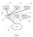
- FIG. 2is a block diagram presenting a configuration of VSRP and VSRP aware devices according to another embodiment of the present invention
- FIG. 3is a block diagram presenting a break between a master VSRP device and a VSRP aware device according to one embodiment of the present invention
- FIG. 4is a block diagram presenting a VSRP aware device utilizing multiple VLANs connected to master and backup VSRP devices according to one embodiment of the present invention
- FIG. 5is a block diagram presenting multiple VSRP aware devices, each utilizing multiple VLANs, connected to a virtual switch according to one embodiment of the present invention
- FIG. 6is a flow diagram pressing a process for initializing a VSRP device within a virtual switch according to one embodiment of the present invention
- FIG. 7is a flow diagram presenting a process that a VSRP device executes during operation in backup mode according to one embodiment of the present invention
- FIG. 8is a flow diagram presenting a process that a VSRP device executes during operation in master confirm mode according to one embodiment of the present invention
- FIG. 9is a flow diagram presenting a process that a VSRP device executes during operation in master mode according to one embodiment of the present invention.
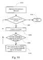
- FIG. 10is a flow diagram presenting a process for calculating a priority value corresponding to the outgoing bandwidth available on each VSRP device comprising a virtual switch according to one embodiment of the present invention
- FIG. 11is a block diagram presenting two VSRP devices acting as two virtual switches, each providing failover to different VLANs, according to one embodiment of the present invention
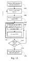
- FIG. 12is a flow diagram pressing a process for providing a converged virtual switch according to one embodiment of the present invention.
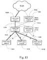
- FIG. 13is a block diagram presenting two virtual switches in a ladder configuration providing, one providing failover redundancy for the other, according to one embodiment of the present invention
- FIG. 14is a block diagram presenting two VSRP devices comprising a virtual switch connected to a ring topology network according to one embodiment of the present invention.
- FIG. 15is a flow diagram presenting a method for configuring and operating a virtual switch connected to a ring topology network according to one embodiment of the present invention.
- Embodiments of a method, system, and article of manufacturecomprising software programs for providing network route redundancy across Layer 2 (L2) and hybrid Layer 2/Layer 3 (L2/L3) devices in accordance with the present invention are described with reference to the drawings in FIGS. 1 through 15 .
- FIG. 1a network topology configured according to one embodiment of the present invention is illustrated.
- the network topology presentedcomprises a number of switches 108 , 110 , 112 , 122 , 124 , 126 performing Layer 2 aggregation and switching functionality.
- each of these Layer 2 devices 108 , 110 , 112 , 122 , 124 , 126is aware of the Virtual Switch Redundancy Protocol or VSRP, described in detail herein, and may thus properly operate with the failover functionality provided by the present invention.
- An exemplary Layer 2 device 108 , 110 , 112 , 122 , 124 , 126is the EdgeIron 4802F switch available from Foundry Networks of San Jose, Calif.
- each of these Layer 2 devices 108 , 110 , 112 , 122 , 124 , 126may also be connected to one or more host devices, hubs, switches, bridges or other network interconnection devices.
- these L2 switchesmay be connected to any arbitrary Layer 2 network topology which is loop free.
- these switchesmay be connected to a network running the spanning tree protocol to eliminate loops.
- the connected networkmay be a ring running the simplified loop prevention protocol described in commonly-owned patent application Ser. No. 10/090,669, filed Mar. 4, 2002, now U.S. Pat. No.
- VSRPmay be employed with the other protocol using techniques described herein.
- another layer of devices 104 , 106 , 118 , 120reside between the VSRP aware devices performing L2 aggregation and switching 108 , 110 , 112 , 122 , 124 , 126 and the network core 114 .
- Each of these devices 104 , 106 , 118 , 120comprises L2 switching functionality and preferably L3 functionality as well.
- These devicesare described as VSRP devices because they communicate with other VSRP devices according to the Virtual Switch Redundancy Protocol (VSRP), as is explained in greater detail herein.
- VSRP devices 104 and 118are also associated with other VSRP devices, 106 and 120 respectively, in order to create virtual switches 102 and 116 , respectively, that operate according to the VSRP protocol.
- the virtual switch 102is connected to each VSRP aware device 108 , 110 , 112 residing directly below the virtual switch 102 in the topology. Specifically, only one of the VSRP devices 104 comprising the virtual switch 102 is in active communication with the VSRP aware devices 108 , 110 , 112 to which it is connected.
- These interconnectionsare presented in bold typeface both here and throughout the disclosure of the present invention as indicative of a connection over which normal network traffic is being passed, e.g., ports on both ends of the connection 104 and 108 are forwarding data. This is in contrast to the interconnections presented in normal typeface where traffic is being blocked. As is explained herein, not all traffic is blocked over ports set to block traffic according to the protocol of the present invention.
- FIG. 2presents an alternative embodiment of a configuration of VSRP and VSRP aware devices.
- VSRP aware switchesare presented 210 , 212 , and 214 .
- These switches 210 , 212 , 214are VSRP aware and are provided with knowledge that they connect a plurality of devices acting in concert as one virtual switch.
- additional network infrastructureresides below this level of devices 210 , 212 , 214 , e.g., hosts and other network interconnect devices, it is by no means a requirement of the present invention.
- Sitting between the VSRP aware switches 210 , 212 , and 214 and the network core 220are a series of VSRP switches 204 , 206 and 208 .
- each of the VSRP switches 204 , 206 and 208communicates with other VSRP switches according to the VSRP protocol. Communication according to the protocol allows devices in a virtual switch to determine whether it should set itself to master mode, backup mode, or an intermediary mode described below, for the group of supported devices, thereby providing failure redundancy and avoiding network loops.
- the VSRP switches 204 , 206 and 208are configured as one virtual switch 202 , providing redundant routes to the network core 220 in the event that the current VSRP master switch 204 within the virtual switch 202 becomes inoperative, e.g., not the optimal switch to be acting as master for a given virtual circuit 202 .
- VSRP aware switch T 210is symmetrically connected to VSRP master switch Q 204 , VSRP backup switch R 206 and VSRP backup switch S 208 , all three of which comprise the virtual switch 202 .
- the only connection forwarding datais the connection with VSRP master switch Q 204 , whereas backup switches R and S, 206 and 208 respectively, are blocking communication.
- each switch 204 in the virtual switch 202is transmitting data, while the other switches 206 and 208 are blocking traffic until the situation arises when one of the two is required to become the master switch, causing the current master switch 204 to transition to backup mode.
- each VSRP switch 204 , 206 , 208must in turn be symmetrically connected to each VSRP aware switch 210 , 212 , 214 that the virtual switch 202 is providing redundancy for. This is true regardless of whether the VSRP device is in master or backup mode.
- a priority valuedetermines whether a VSRP device is in master or backup mode.
- One of the factors in determining priority valueis the number of connections the VSRP device has vis-à-vis other VSRP devices comprising the same virtual switch.
- FIG. 3presets a situation where the VSRP device currently in master mode 304 has lost communication 314 with a VSRP aware switch 310 located on the far side of an intermediate hub 308 , which is an unmanaged device.
- detailed knowledge of the overall networkis not required, only knowledge that the VSRP aware switches being backed up are symmetrically connected to the VSRP switches comprising the virtual switch.
- Knowledge at each VSRP switch comprising the virtual switch that a “live” connection exists to every immediate supported neighbor (here, a VSRP aware switch)is necessary in order to provide failover when an outage occurs.
- each VSRP switch 304 and 306In order to determine the number of connections each VSRP switch 304 and 306 has to VSRP aware switches 310 and 312 , it is necessary to do more than simply count the ports that are connected at the VSRP switch 304 and 306 . Knowledge of a physical connection at a particular port on a VSRP switch 304 and 306 , regardless of the connection status, is not helpful in determining a switch's ability to connect to the virtual switch's neighbors. Therefore, in order to determine the number of “live” connections, each VSRP switch 304 and 306 broadcasts L2 health check packets, independent of the VSRP hello packets discussed elsewhere herein. The Layer 2 heath check is essentially a query broadcast by the VSRP device 304 and 306 on all of its interfaces.
- Each L2 devicee.g., VSRP aware switches 310 and 312 , that receives the Layer 2 heath check packet broadcast by the VSRP switch 304 and 310 respond with a response packet identifying the device. According to some techniques, extended device data is returned. Software executing on the VSRP router is used to advertise aggregated L2 connection information, along with additional data, to other VSRP routers comprising the same virtual switch in order to make election decisions.
- the L2 health check performed here by the VSRP switches 304 and 306results in VSRP switch D 306 recording that it has two live connections, while VSRP switch C, the current master switch for the virtual switch 302 , announces only one connection. This information is then taken into account as parameters in the election process performed at each VSRP device comprising a virtual switch to determine if another device should transition into master mode with the current master transitioning into backup mode and blocking ports that are currently forwarding.
- the number of live connections determined through the use of health check packetsis a factor in determining the priority assigned to the respective switch, which priority is then inserted into the VSRP hello packets as discussed herein.
- FIG. 4presents an embodiment of the invention where a VSRP aware switch 408 assigns individual ports on the switch membership in different VLANs 414 and 416 .
- a VSRP aware switch 408assigns individual ports on the switch membership in different VLANs 414 and 416 .
- an administratormay use multiple switches to mimic the effect of having one physical segment.
- a virtual switch 402supplying the VSRP aware switch 408 with a communications path to other segments of the network (not pictured).
- the virtual switch 402comprises two VSRP switches 404 and 406 .
- Functionalityis provided at the VSRP switch 404 and 406 so that traffic destined for either of the VLANs on the VSRP aware switch 408 is forwarded by the VSRP master switch 406 over the forwarding link 418 .
- the link between the VSRP aware switch 408 and the VSRP backup switch 404is set to blocking 420 so as to prevent a network loop, until such time as the VSRP backup switch is required to transition into master mode.
- Each host, e.g., 410 , 412 , etc., that is connected to the VSRP aware physical LAN segment 408is assigned membership in a specific virtual LAN, e.g., 416 . In this manner, traffic received by the switch 408 is not broadcast to all physically connected hosts 410 and 412 .
- a command line interface(CLI) to access and set parameters used by software at the VSRP switch in providing redundancy
- an administratormay set a virtual switch 402 to provide redundancy for only selected VLANs 414 and 416 on a VSRP aware switch 408 .
- software in the VSRP switchallows an administrator to create a topology group whereby one VLAN is set as the master VLAN for the group.
- the topology groupis also bound to or associated with one or more additional VLANs. This binding of master and member VLANs is required due to the fact that each physical interface on a switch may only be associated with an individual VLAN. Software in the VSRP switch is configured to catch and respond to traffic destined for the master and member VLANs, thereby providing failover protection for the topology group.
- the topology presented in FIG. 4satisfies the requirement that the connections 418 and 420 between the VSRP aware switch 408 and the virtual switch 402 are symmetrical.
- An administratormay set the virtual switch 402 to provide redundancy for only VLAN 1 ( 416 ).
- the VSRP switches 404 and 406are configured to broadcast traffic on only VLAN 1 ( 416 ), thereby requiring an additional communications path (not pictured) to broadcast traffic destined for VLAN 2 ( 414 ).
- an administratorcreates a new topology group setting VLAN 1 as the master VLAN and binding VLAN 2 as a member VLAN.
- the election process of the present inventionis executed by software in each VSRP switch 404 and 406 comprising the connected virtual switch 402 to determine the VSRP switch it should set itself to master or backup mode.
- the VSRP master switchforwards traffic for all members of the topology group until such time as the VSRP master switch is required to transition into backup mode.
- FIG. 5builds on the embodiment of the system presented in FIG. 4 .
- VSRP aware switches 508 , 510 and 512Each of the VSRP aware switches presented here 508 , 510 and 512 has partitioned its ports between two VLANs: VLAN 1 and VLAN 2 , so at to thereby mimic two physical network segments. Traffic received on each of the VSRP aware switches 508 , 510 and 512 is not broadcast to every host physically connected to the switch according to this configuration. Instead, traffic is tagged as destined for a particular VLAN, with the VSRP aware switch broadcasting packets only to ports that are members of the target VLAN. Hosts attached to different physical LAN segments, therefore, appear as one logical LAN.
- a virtual switch 502provides a redundant connection to an outside network or network segments for the VSRP aware switches 508 , 510 and 512 .
- the virtual switch 502is comprised of two VSRP switches: a VSRP master switch 504 and VSRP backup switch 506 . It should be noted that additional VSRP switches may be added to the virtual switch 502 in order to provide additional failover capacity.
- the VSRP switch acting as the VSRP master switch 504 for the virtual switch 502sets all its ports to forward data, represented by bold lines interconnecting the VSRP master switch 504 with the VSRP aware switches 508 , 510 , 512 .
- the virtual switch 502is configured to provide failover protection for both of the VLANs on the VSRP aware switches 508 , 510 , and 512 by binding the two VLANs into a single topology group. Binding of VLANs into topology groups is accomplished through programming at the VSRP switch's command line interface.
- the present inventionis concerned with providing redundancy protection for Layer 2 devices in large switched networks, as well as preventing problematic network loops whereby hosts appear on multiple interfaces of the same device.
- the inventionaccomplishes these objectives by associating two or more VSRP switches into a virtual switch, thereby providing redundancy protection, and setting only the ports of one VSRP switch to forward and the rest to block.
- a hello packet 514is used by each VSRP backup switch 506 to determine, based on the status of received hello packets in the same virtual switch 502 , whether it should be in master mode (ports forwarding), blocking mode (ports blocking), or an intermediary “master confirm” mode (ports blocking to traffic but transmitting hello packets).
- Each hello packet 514 transmitted by the VSRP switch in master modecomprises data that indicates the transmitting VSRP switch's state, which is determined on the basis of a number of factors. Of high importance is the priority value, which among other factors is based on the number of connections that the VSRP switch has to the virtual switch's neighbors, e.g., the switches for which redundancy is being provided.
- the VSRP switches 504 and 506are symmetrically connected to the supported VSRP aware switches 508 , 510 , and 512 .
- the VSRP switches 504 and 506may also export this priority data for utilization with other software applications that monitor and respond to network health issues, such as the IronView switch and INM product available from Foundry Networks.
- the priority data comprising the hello packet 514is based on the relative quality of the VSRP switch's connection to the outside network or network segments.
- the VSRP switchuses a tracking value, defined in the switch, to modify the priority value with regard to the fluctuating quality of its connection to the outside network.
- other datamay be broadcast as part of the hello packet, such as the VSRP switch's MAC address, IP address, and other miscellaneous data that may be used by software executing on other switches in the virtual switch 502 to deduce whether to transition into master or backup mode.
- the VSRP master switchsets its ports to forwarding and continues to send out hello packets.
- VSRP backup switchesset their ports to blocking and receive hello packets to determine if they should remain in backup mode or transition to master mode; hello packets are permitted transmission over blocked ports on the VSRP backup switch 506 .
- the connected VSRP aware switches 508 , 510 and 512receive the hello packets 514 and 516 .
- Each VSRP aware switch 508 , 510 and 512floods the hello packet upon receipt, which is received by other VSRP switches 504 and 506 in the virtual switch 502 due to the symmetrical nature of the connection topology. As understood by those skilled in the art, flooding generally occurs when a packet is forwarded to all devices other than the device from which it was received, and is generally performed when the packet has no routing address.
- a direct linkmay be provided between VSRP devices 504 and 506 as a primary channel for transmission of hello packets to reduce extraneous administrative traffic on the network; a flooding technique may be used regardless of the primary link or only in the event the primary link fails.
- the primary linkimproves the efficiency of and synchronicity between the VSRP configured or aware switches, because the direct/primary link ensures the timely delivery of hello packets.
- a control mechanismis used to prevent overflooding.
- a time-to-live (TTL) packetis attached to the VSRP hello packet, which TTL is decremented each time the packet is transferred through a VSRP switch.
- TTLtime-to-live
- the VSRP aware switchesare arranged in a multiple layer topology, such as a ladder topology (in which each pair of a series of VSRP backup switches is connected to another pair of VSRP backup switches in symmetrical fashion)
- the TTLis set so that it counts down to zero when the hello packet reaches the intended VSRP backup switch(es) in the ladder topology, thus stopping the hello packet from continuing to circulate.
- the TTLshould not be decremented so as to prevent the packet from timing down to zero before it reaches the other VSRP aware devices.
- the VSRP aware switchesmay, in accordance with the invention, be connected to a Layer 2 network with arbitrary, albeit loop free, configuration, which network is running another protocol to prevent loops and provide redundancy.
- a linear topologysuch as a ring configuration described below. Any devices in the connected network not running VSRP do not decrement the VSRP packet TTL.
- a default TTL valueis provided in the hello packet generation software executing in the VSRP switches.
- Network administratorsaware of the network topologies connected to the VSRP switches, may set or change the TTL value through a command line interface with the switches.
- FIGS. 6 through 10present processes for implementing and operating a virtual switch as presented in FIGS. 1 through 5 .
- the process executed by software executing on the VSRP switchtypically begins by cycling the power on or resetting all devices comprising the virtual switch, step 602 .
- the current part of the processis typically only executed when the virtual switch is initialized.
- each of the VSRP switches comprising the virtual switchtransitions to backup mode, step 604 .
- a countdown variablereferred to as C 1 , step 606 .
- Each VSRP switch in backup modeexecutes the process illustrated in FIG. 7 to determine if a transition to a new mode is required based on its own state versus the state of other VSRP switches in the virtual switch.
- the processbegins 700 with the VSRP switch set to backup mode, step 702 .
- a VSRP switch in backup modesets all of its port to a blocking state whereby only hello packets are accepted over the port; regular network traffic is denied.
- the VSRP switchalso initializes a countdown variable to the value C 1 , step 702 .
- the countdown variableis used by the VSRP switch when in backup mode to determine if no other device in the same virtual switch is in master mode and transmitting hello packets, thereby indicating that the switch in backup mode should transition to master mode.
- a switch administratoruses the VSRP switch's command line interface to define the initial value of the countdown variable.
- each VSRP switch within a given virtual switchmay initialize the countdown variable to a different value if desired.
- the deviceis initialized, step 702 , and the VSRP switch decrements the countdown variable, step 704 .
- the VSRP switch in backup modeexecutes two processes in parallel in order to determine its proper mode. After the switch decrements the countdown variable, step 704 , a check is performed to determine if the countdown variable is equal to zero, step 706 . If the countdown variable is not set to zero, step 706 , control returns to step 704 where the VSRP switch once again decrements the countdown variable. Where the countdown variable is equal to zero, step 706 , the time threshold to receive hello packets from a device or devices in master mode has been exceeded, thereby causing program flow to pass to step 708 where VSRP switch transitions from backup mode to master confirm mode. The transition is performed where no hello packets have been received in the countdown window due to the fact that this condition is indicative of no other device comprising the virtual switch being in master confirm mode.
- steps 706 and 708another process awaits receipt of one or more hello packets from the device or devices attempting to act as the VSRP master switch for the virtual switch, steps 710 , 712 , 714 , and 716 .
- the processwaits while the previously described parallel process, steps 704 , 706 , and 708 , continues to decrement the countdown variable.
- a hello packetis received from a device in master mode, step 710 , it is analyzed to retrieve the data values contained therein, e.g., priority value for the VSRP switch that is transmitting the packet.
- the VSRP switchextracts the priority value and performs a check to determine whether it has a higher priority value than the priority value contained in the received hello packet, step 712 .
- the VSRP switchdetermines that the priority value contained in the received hello packet is greater than its priority value, step 712 , the VSRP switch concludes that it should remain in backup mode as another device is properly acting as the master VSRP switch for the virtual switch.
- the VSRP switchreinitializes the countdown variable to C 1 , step 716 and program flow returns to step 704 where the process is repeated. If, however, the VSRP switch determines that its priority value is greater than that contained in the received hello packet, the VSRP switch concludes it should potentially be the master VSRP switch.
- the VSRP switchtransitions into an intermediate mode between backup and master mode referred to as master confirm mode, step 714 .
- the parallel process run by the software to maintain the timer mechanism, steps 706 and 708is killed when the VSRP switch transitions to master confirm mode.
- the process executed by the VSRP switch upon entering master confirm modeis introduced in FIG. 8 .
- the processbegins, step 800 , when the device transitions into master confirm mode, at which point the VSRP software initializes a countdown variable and a hello counter, step 802 .
- the countdown variableis used as a timer to trigger the transmission of hello packets.
- the hello counteris maintained to set a threshold number of hello packets to transmit, at which point the VSRP switch transitions into master mode if it hasn't already transitioned to backup mode and thus terminated sending hello packets.
- the countersare initialized, step 802 , and the software executing at the VSRP switch decrements the countdown variable, step 804 .
- the processes performed by the switch in master confirm modeare similarly executed in parallel.
- the timer processis explained first, steps 806 , 808 , 810 , 812 , 814 , and 816 , followed by an explanation of the packet comparison process, steps 818 , 820 , 822 , and 824 .
- step 804When the software decrements the countdown variable, step 804 , a check is performed to determine if the countdown variable is equal to zero, step 806 . Where the countdown variable is not equal to zero, step 806 , the process once again decrements the countdown variable, step 804 , and so forth until the variable is equal to zero, step 806 . When the countdown variable reaches zero, step 806 , the software decrements the hello counter variable, step 808 .
- the VSRP switchtransmits hello packets indicating its current priority on all of its ports that are not outgoing ports connected to an outside network, step 810 .
- the hello packetsare transmitted, step 810 , and a check is performed to determine if the hello counter is set to zero.
- the softwareresets the countdown variable, step 806 , and program flow for this portion of the parallel process returns to step 804 . If the hello counter has expired and the VSRP switch is still in master confirm mode, the software operating at the VSRP switch concludes that it should be the VSRP master switch and transitions into master mode.
- a processawaits receipt of one or more hello packets from the device or devices attempting to act as the VSRP master switch for the virtual switch, steps 710 , 712 , 714 , and 716 . Where no hello packet is received, the process waits while the previously described parallel countdown process, steps 806 , 808 , 810 , 812 , 814 and 816 , continues to decrement the countdown variable, hello counter, and transmit hello packets as is appropriate.
- a hello packetis received from a device in master mode or master confirm mode, step 818 , it is analyzed to determine the data values contained therein, e.g., priority value for the VSRP switch that is transmitting the packet. Because multiple devices may simultaneously be in master confirm mode, the VSRP switch may receive one or more hello packets, step 818 .
- the number of potential hello packetsis also a function of the number of devices comprising the virtual switch.
- the VSRP switchreceives the hello packet or packets and performs a check to determine whether its priority is greater than that contained in any of the hello packet or packets, step 820 .
- a hello packetis transmitted containing the VSRP switch's priority value and this portion of the parallel process concludes until the next hello packet is received, step 818 . If, however, the VSRP switch calculates that the received hello packet contains a greater priority value, the VSRP concludes that another device is the proper VSRP master for the virtual switch and therefore transitions into backup mode and sets its ports to blocking, step 822 .
- the parallel processrun by the software to maintain the timer mechanism, steps 806 , 808 , 810 , 812 , 814 and 816 , is killed when the VSRP switch transitions to backup mode. According to embodiments of the invention, the switch's ports remain blocked when in master confirm mode so as to prevent temporary network loops.
- the VSRP switch in master confirm modetransmits the number of hello packets as defined by the hello counter variable, step 812 , and no other device is broadcasting a higher priority value, step 820 .
- the VSRP switchconcludes it should be the VSRP master and transitions to master mode. Consistent with performance of the VSRP switch in master mode, the VSRP switch sets all its ports from blocking to forwarding, thereby allowing the regular flow of network traffic over its ports.
- the process executed by the VSRP switch in master modeis illustrated in FIG. 9 . The process begins, step 900 , when the device transitions into master mode, at which point the VSRP software initializes a countdown variable, step 902 .
- the countdown variableis used as a timer to trigger the transmission of hello packets in the event the VSRP fails to receive hello packets from another device in the virtual switch.
- the countersare initialized, step 902 , and the software executing at the VSRP switch decrements the countdown variable, step 904 .
- the processes performed by the switch in master modeare similarly executed in parallel.
- a checkis performed to determine if the countdown variable is set to zero, step 906 . Where the countdown variable is not equal to zero, step 906 , the process once again decrements the countdown variable, step 904 , and so forth until the variable is equal to zero, step 906 .
- the VSRP switchtransmits hello packets over its ports connect to the managed VSRP aware switches, step 908 .
- the hello packetsare transmitted, step 908 , and the countdown variable is reinitialized, step 902 .
- a parallel process for performing analysis of received hello packetsis triggered upon receipt of a hello packet, steps 908 , 910 , 912 , and 914 .
- a hello packetis received from a challenging device in master confirm mode, step 910 , it is analyzed to determine the data values contained therein, e.g., priority value for the VSRP switch that is transmitting the packet.
- the VSRP switchmay receive one or more hello packets, step 910 .
- the number of potential hello packetsis also a function of the number of devices comprising the virtual switch.
- the VSRP switchreceives the hello packet or packets and performs a check to determine whether its priority is greater than that contained in any of the hello packet or packets, step 912 .
- a hello packetis transmitted containing the VSRP switch's priority value, step 908 , and this portion of the parallel process concludes until the next hello packet is received, step 910 . If, however, the VSRP switch calculates that a received hello packet contains a greater priority value, step 912 , the VSRP concludes that another device is the proper VSRP master for the virtual switch and therefore transitions into backup mode and sets its ports to blocking, step 914 .
- the parallel processrun by the software to maintain the timer mechanism, steps 906 and 908 , is killed when the VSRP switch transitions to backup mode.
- the aware switchWhen a switch in the virtual switch transitions from master to backup the aware switch detects this condition by receiving the VSRP hello packet from a port different than the one that connects it to the old master. The aware switch transfers its MAC entries on the old master port to the new master port. This assists in quick failover recovery and data convergence which, in some embodiments, may be accomplished in a sub-second time frame.
- hello packets transmitted by switches in master or master confirm modecarry a hello timer which is communicated to the backup switches.
- the backup switchesuse the hello timer to synchronize their time values with those of the master switch. This further assists in stabilization of the network.
- Some embodimentsfurther employ an authentication process for hello packets, wherein a password is sent with the hello packet, which gets authenticated at the receiving switch.
- each VSRP deviceupdates its priority value with regard to the quality of its outbound connection on an arbitrary or periodic basis.
- FIG. 10presents an embodiment of a process executed by the VSRP switch to modify its priority value vis-à-vis available outbound bandwidth.
- Each VSRP switchis configured with a low bandwidth threshold value, which is retrieved from storage or memory, step 1002 . This low bandwidth threshold may be set by a switch administrator using the CLI to set the parameter in the VSRP switch's software. Looking at the switches from any given virtual switch as a group, a check is performed to determine if additional VSRP switches need to execute the priority update, step 1004 . It should be noted that software at each VSRP switch performs this analysis in parallel without input from other VSRP switches in the virtual switch or any other controlling device. The loop presented here, therefore, is for the purpose of clarity in the presentation only.
- step 1004another device in the virtual switch is analyzed, step 1006 .
- Software executed by the VSRP switche.g., priority calculation software, takes a measurement of the bandwidth available on the interface connecting the VSRP switch to the outside network or network segments, step 1006 .
- a multitude of available techniquesare well known to those skilled in the art for measuring the bandwidth available on a given link, for example, the Pathchar Algorithms, used in the tools pathchar and utimer, and the family of algorithms based on the Packet Pair algorithm used in the tools bprobe, cprobe, and tcpanaly.
- the measured bandwidth available to the VSRP switchis compared against the low bandwidth threshold set at the CLI, step 1006 .
- a switch's prioritysuch as a periodic “ping” to a known router outside the network to ensure a connection to the outside network, wherein the priority is decreased if the “ping” fails to go through.
- a checkis performed by software at the VSRP switch to determine if the calculation comparing the available bandwidth against the low bandwidth threshold results in the threshold being exceeded, step 1008 . If the available bandwidth exceeds the threshold, the VSRP switch decrements its priority value by the tracking value, step 1010 .
- the tracking valueis a mechanism that allows a VSRP switch with poor bandwidth to the outside network to advertise this fact and allow it and other VSRP switches in the same virtual switch to take this into account when determining if they should be in master or backup mode.
- the tracking valueis loaded into the VSRP switch's software by a switch administrator at the CLI. It should be noted that various types of aging mechanisms, such as are well known to those of skill in the art, may also be employed to increase the priority as available bandwidth improves.
- step 1008the priority value remains unmodified and the switch's analysis is complete for this iteration of the priority update.
- Program flowreturns to step 1004 where a check is performed to determine if additional VSRP switches forming the virtual switch need to update their priority value.
- the subroutineends when all devices in the virtual switch have been updated, step 1012 .
- the application of the present invention to the topology presented in FIG. 5is built on with the topology presented in FIG. 11 .
- several VSRP aware switchesare provided 1108 , 1110 and 1112 .
- Each of the VSRP aware switches presented here 1108 , 1110 and 1112has partitioned its ports between two VLANs.
- VSRP aware switches A and C, 1108 and 1112 respectivelyhave assigned their ports to VLANs 1 ( 1114 ) and 2 ( 1116 ), whereas VSRP aware switch B 1110 has assigned its ports to VLANs 3 ( 1118 ) and 4 ( 1120 ).
- Traffic received on each of the VSRP aware switches 1108 , 1110 and 1112is not broadcast to every host physically connected to the switch. Instead, traffic is tagged as destined for a particular VLAN, with the VSRP aware switch broadcasting packets only to ports that are members of the target VLAN. Hosts attached to different physical LAN segments, therefore, appear as one logical LAN.
- two virtual switchesare created from two physical VSRP switches 1104 and 1106 , each of the virtual switches providing redundancy protection for a different group of VLANs.
- Each virtual switch 1102is configured to provide failover protection for selected VLANs on the VSRP aware switches 1108 , 1110 , and 1112 by binding two VLANs into a single topology group, which is programmed at the VSRP switch's CLI interface, and assigning it to a virtual switch.
- each VSRP switch 1104 and 1106is assigned a virtual switch identifier (VSID) for each virtual switch that the VSRP switch is a member of; each VSID is associated with a virtual switch and topology group. It should be noted that additional VSRP switches might be added to the virtual switch 1102 to provide additional failover capacity.
- VSIDvirtual switch identifier
- the VSRP switch acting as the VSRP master switchsets all its ports to forward data for the supported VLANs, represented by bold lines interconnecting the VSRP master switch with the VSRP aware switches 1108 , 1110 , 1112 . All other VSRP switches in the stable virtual switch are set to backup mode, setting their ports to blocking (except for hello messages).
- topology group 1comprises VLANs 1 and 2
- topology group 2comprises VLANs 3 and 4
- VSRP switch 1104is the master VSRP switch for topology group one, while simultaneously acting as the VSRP backup switch for topology group 2 .
- VSRP switch 1104sets ports connected to VSRP aware switches A and C (topology group 1 ), 1108 and 1112 , to forwarding and the ports connected to VSRP aware switch B (topology group 2 ) as blocking.
- VSRP switch 1106is the master VSRP switch for topology group two, while simultaneously acting as the VSRP backup switch for topology group 1 .
- VSRP switch 1106therefore, sets ports connected to VSRP aware switches A and C (topology group 1 ), 1108 and 1112 , to blocking and the port connected to VSRP aware switch B (topology group 2 ) as forwarding.
- Thisis an excellent example of how the present invention provides the redundancy features of a protocol such as VRRP, as well as the benefits of a protocol such as STP by preventing undesirable network loops.
- Each VSRP switch in master mode 1104 and 1106broadcasts hello packets 1122 and 1124 for each virtual switch in which the VSRP switch is a VSRP master.
- Other VSRP switchesreceive the hello packets 1122 and 1124 and act up on them if the receiving VSRP switch is a member of the virtual switch that the hello packet is destined for. If the receiving VSRP switch is a member of the virtual switch that the hello packet is destined for, the packet is used by the receiving VSRP switch's software.
- the VSRP switch's softwareextracts the data contained in the received hello packet to determine whether it should be in master mode, master confirm mode, or blocking mode for the given virtual switch that the hello packet belongs to (and of which the VSRP switch is a member). Where the VSRP switch receives hello packets for a virtual switch that the VSRP switch is not a member of, the packet is ignored. Alternatively, it may continue to be propagated throughout the network.
- Each hello packet 1122 and 1124comprises information regarding the transmitting VSRP switch's state and membership.
- the VSRP switchbroadcasts hello packets for each virtual switch for which it is a master.
- Each broadcast hello packetis tagged with a virtual switch identifier (VSID) indicating the virtual switch to which it belongs and, therefore, the VLANs for which it is providing redundancy.
- VSIDvirtual switch identifier
- These packetsare acted on as is appropriate by other VSRP switches that are members of the same virtual switch, e.g., depending on the VSRP switch's current mode. Also of high importance is the priority value that the VSRP switch has, which is used by other VSRP switches in the virtual switch to determine if a mode change is appropriate.
- the data in hello packets for different virtual switches broadcast by the same physical devicemay be different.
- the VSRP switches 1104 and 1106are symmetrically connected to the supported VSRP aware switches 1108 , 1110 , and 1112 . Discrepancies in the number of connections to a particular VLAN between VSRP switches 1104 and 1106 that are members of the same virtual switch is reflected in the priority value.
- the priority valueallows a VSRP switch to realize if the connection symmetry is broken for a particular virtual switch, at which VSRP switch or switches the break or breaks are occurring, and assist it in making a decision regarding the proper mode to be in for that virtual switch.
- the VSRP switches 1104 and 1106may also export this data for utilization with other software applications that monitor and respond to network health issues.
- the priority value contained in the hello packetmay be modified according to the relative quality of the switch's connection to the outside network or network segments for a given virtual switch.
- Each VSRP switchcomprises a tracking value, not included as part of the data comprising the hello packet, which is used to modify the priority value as the quality of the outside connection fluctuates.
- other datais broadcast, such as the VSRP switch's MAC address, IP address, and other miscellaneous data that may be used by software executing on other switches in the virtual switch to deduce whether to transition into master or backup mode.
- Each VSRP switch 1104 and 1106broadcasts hello packets 1122 and 1124 for the virtual switches that it is a VSRP master for over its connected interfaces; hello packets are permitted transmission over blocked ports on a VSRP backup switch.
- Each VSRP aware switch 1108 , 1110 and 1112receives the hello packets.
- Each VSRP aware switch 1108 , 1110 and 1112floods the hello packet upon receipt, which is received by other VSRP switches due to the symmetrical nature of the topology.
- the VSRP switchesact on the hello messages as is appropriate for each virtual switch.
- a direct linkmay be provided between VSRP devices 1104 and 1106 as a primary channel for transmission of hello packets to reduce extraneous administrative traffic on the network.
- each VSRP switchmay be configured such that the VSRP switch is a member of more than one virtual switch.
- the VSRP switchretrieves parameters for the first virtual switch of which it is a member, step 1202 .
- Data associated with the currently selected virtual switch's virtual switch identifier (VSID)is used in generating hello packets and in analyzing received hello packets that are intended for the current virtual switch.
- the VSRP switchUpon retrieving data for the current VSID, in this instance the first virtual switch, the VSRP switch initializes itself for the current VSID, step 1204 .
- the process executed by the VSRP switch in backup modealways results in every VSRP switch in virtual switch transitioning to master mode. Referring to the flow diagram presented in FIG. 7 , no hello packets are ever received before the countdown process completes because all switches are initially in backup mode, as indicated in FIG. 6 . This results in each VSRP switch transitioning to master confirm mode, wherein each VSRP switch transmits hello packets for the current VSID upon completion of the countdown process.
- each VSRP switch in the current virtual switchexamines the set of received hello packets. Based on the results of its priority comparison check, each VSRP switch in the current virtual switch transitions into backup mode or remains in master mode and continues to broadcast hello packets to other VSRP switches, step 1208 .
- This state of equilibriumwhereby a virtual switch has one VSRP master and one or more VSRP backup switches, is referred to as “convergence”—the virtual switch and each VSRP switch comprising it has converged at a stable configuration.
- Step 1212represents the sub-process executed by the VSRP switch for each converged virtual switch of which it is part.
- a VSRP switchexecutes the processes for the specific mode it is in for each virtual switch of which it is a member.
- the VSRP switchexecutes processes in a multithreaded fashion according to the mode it is in for each virtual switch of which it is a member.
- the VSRP switchperforms a check to determine if it is a member of additional virtual switches, step 1214 . Where there are additional virtual switches that must be initialized and converged, the VSRP switch loads data for the next virtual switch by retrieving parameters associated with the next virtual switch's VSID, step 1216 . Program flow returns to step 1204 where the VSRP switch initializes itself vis-à-vis the current VSID. If, however, there are no additional virtual switches that the VSRP switch is a member of that require initialization and convergence, the VSRP switch continues to execute the processes associated with the mode it is in for each virtual switch in a multithreaded fashion, step 1212 .
- FIG. 13Another configuration of the invention is presented in FIG. 13 .
- VSRP switches 1304 , 1306 , 1310 , and 1312are presented in a ladder configuration whereby one virtual switch 1302 is used to provide redundancy for another virtual switch 1308 .
- several VSRP aware switches 1314 , 1316 , and 1318are provided that typically perform Layer 2 aggregation and switching functionality.
- each of these Layer 2 devices 1314 , 1316 , and 1318is “VSRP” aware, meaning it may properly operate with the failover functionality provided by the VSRP switches of the present invention.
- Each of these Layer 2 devices 1314 , 1316 , and 1318may also be connected to one or more host devices, hubs, switches, bridges or other network interconnection devices.
- the VSRP aware switches 1314 , 1316 , and 1318are symmetrically connected to a pair of VSRP switches 1310 and 1312 .
- the VSRP switchesoperate in concert whereby one device is in master mode 1312 and the other device is in backup mode 1310 .
- the VSRP master 1312sets its ports to forward network traffic while the VSRP backup 1310 blocks traffic over all its ports.
- the VSRP switchesform a virtual switch 1308 .
- a second virtual switch 1302configured so as to provide network route redundancy to the network core for the virtual switch 1308 that itself is providing redundant paths to the managed VSRP aware switches 1314 , 1316 and 1318 .
- the VSRP switches 1304 and 1306perform mode transitions, shown in FIGS. 6 through 10 , and converge to a stable configuration whereby one VSRP switch is in master mode and other VSRP switches in the same virtual switch are in backup mode.
- a device in backup modesets all its ports to blocking. Based upon this requirement, no network traffic except hello packets may traverse any data path that either begins or ends at a VSRP backup switch. Therefore, the data paths between VSRP master switch 1312 and VSRP backup switch 1304 , VSRP master switch 1306 and VSRP backup switch 1310 , and VSRP backup switch 1304 and VSRP backup switch 1310 are all blocked. According to the two converged virtual switches 1302 and 1308 , only one path 1320 is available over which network traffic to and from the network core may pass. Unfavorable network loops are thereby avoided. Multiple virtual switches may be layered in this manner in order to provide a multiple levels of failover fault tolerance in providing a route to the network core.
- the present inventionis useful in attaching networks utilizing a virtual switch for a fault tolerant connection to Layer 2 loop free network, such as a spanning tree network, to provide fault tolerant communications between the two.
- Layer 2 loop free networksuch as a spanning tree network
- Another exampleis a ring network, such as presented in FIG. 14 and described in commonly owned U.S. patent application. Ser. No. 10/090,669, filed Mar. 4, 2002 now U.S. Pat. No. 6,717,922, entitled “NETWORK CONFIGURATION PROTOCOL AND METHOD FOR RAPID TRAFFIC RECOVERY AND LOOP AVOIDANCE IN RING TOPOLOGIES”, said application being incorporated herein by reference.
- This applicationdescribes a specific ring network to which the present invention is suited for providing connectivity.
- a virtual switch 1402is used to provide redundancy protection for a set of VSRP switches 1408 and 1410 .
- the virtual switch 1402comprises two VSRP switches operating in concert to provide this redund
- the VSRP switches 1404 and 1406conduct regular elections to determine whether they should be in master mode (forwarding packets) or in backup mode (blocking packets) for each virtual switch 1402 to which they belong.
- VSRP master switch 1404is providing an open connection to the VSRP switches 1408 and 1410 , while VSRP backup switch 1406 is waiting to take over in the event that the VSRP master fails. According to the present configuration of the invention, however, not all of the ports on the VSRP backup switch 1406 are set to blocking.
- each of the VSRP switches comprising the virtual switchmust be connected to the outside network, in this case a ring topology.
- the ring topologyadds the additional constraint that, because data must be able to flow freely from the beginning to the end of the ring, data must always pass between both VSPR switches as shown by the bold interconnect between the two devices 1404 and 1406 and the ring.
- the interfaces exposed by a VSRP switch (or virtual switch) to the ring networkmust always be set to forwarding in order to preserve the continuity of the ring.
- VSRP switches 1404 and 1406each have their interconnecting ports and the port belonging to the ring topology controlled by the metro ring protocol, while the port connected to the VSRP aware switches 1408 and 1410 are controlled by VSRP.
- some portscan belong to VSRP while others belong to the network's fault redundancy protocol.
- Each VSRP device 1404 and 1406 in the virtual switch 1402 connected to the ringmust have its interfaces that are exposed to the ring, and that are controlled by the ring's fault redundancy protocol, always set to forward data due to the implicit features of the ring topology.
- This implicit featurearises from the fact that a ring is defined as intact when data moves from a starting point on the ring (forwarding port) and arrives on the starting point's opposite interface connected to the other end of the ring (blocking port).
- a master device 1412controls the ring network. Optimally, the start and end points of the ring should be the master's interfaces 1412 , whereby one interface is set to blocking and the other is set to forwarding.
- Datapasses through the ring from the master's forwarding port to other devices connected to the ring, 1414 , 1416 and 1418 .
- the ringwould be broken if the VSRP switch's interfaces exposed to the ring were set to blocking, thereby causing the master 1412 to reconfigure the ring to work around the fault and diminish the fault tolerance features of the virtual switch in providing a connection to the ring.
- a switch administratorinstructs each VSRP switch 1404 and 1406 to keep all ports exposed to the ring network, regardless of whether it is in master or backup mode.
- a direct physical connectionis provided between the VSRP switches 1402 and 1406 . This direct connection is required due to the fact that without it the VSRP backup switch would have no other route to broadcast the packets passed over the ring because all its other ports are blocking. The interfaces used for this direct connection are also set to forwarding regardless of the VSRP switch's mode.
- the virtual switchprovides redundancy functionality for the supported VSRP switches as previously explained through reference to various embodiments of the invention as presented in the accompanying figures.
- a method of operating a virtual switch of the present invention in conjunction with a network configured according to a ring topologyis shown in the flow diagram presented at FIG. 15 .
- An administrator or other similar network engineer physically wiring the networkidentifies the ports comprising the VSRP switches in the virtual switch that constitute a portion of the ring topology, step 1502 , which are interconnected to preserve the continuity of the ring topology.
- a switch administratoruses the command line interface provided by the software executing on each VSRP switch, a switch administrator instructs the software that the ports selected as connected to the ring topology, the ring protocol in turn, instructs these ports to be always set to forwarding, step 1504 .
- ports selected for connection to the supported VSRP aware switchese.g., ports forming the virtual switch, resulting in VSRP switches in the virtual switch being symmetrically connected to the supported VSRP aware switches, step 1506 .
- the VSRP switchis physically connected in the proper manner to the ring topology and supported VSRP switches, steps 1502 and 1506 , and the ports are configured via the VSRP software's command line interface, step 1504 .
- the switches comprising the virtual switchare initialized, e.g., reset or their power is cycled, in order to start the initialization process presented in FIG. 6 , step 1508 .
- no hello packetsare ever received before the countdown process completes because all switches are initially in backup mode, as indicated in FIG. 6 .
- each VSRP switch in the current virtual switchexamines the set of received hello packets. Based on the results of its priority comparison check, each VSRP switch in the current virtual switch transitions into backup mode or remains in master mode and continues to broadcast hello packets to other VSRP switches, step 1512 . Changes in the priority value of a VSRP switch in the virtual switch that impact which switch should be VSRP master and which switches should be VSRP backup causes the appropriate software processes in each switch to transition modes accordingly, step 1514 , in order to maintain a stable converged configuration.
Landscapes
- Engineering & Computer Science (AREA)
- Computer Networks & Wireless Communication (AREA)
- Signal Processing (AREA)
- Computer Security & Cryptography (AREA)
- Environmental & Geological Engineering (AREA)
- Data Exchanges In Wide-Area Networks (AREA)
- Small-Scale Networks (AREA)
Abstract
Description
Claims (18)
Priority Applications (5)
| Application Number | Priority Date | Filing Date | Title |
|---|---|---|---|
| US10/124,449US7209435B1 (en) | 2002-04-16 | 2002-04-16 | System and method for providing network route redundancy across Layer 2 devices |
| US11/695,458US7558195B1 (en) | 2002-04-16 | 2007-04-02 | System and method for providing network route redundancy across layer 2 devices |
| US12/477,069US8014301B2 (en) | 2002-04-16 | 2009-06-02 | System and method for providing network route redundancy across layer 2 devices |
| US13/185,885US8593987B2 (en) | 2002-04-16 | 2011-07-19 | System and method for providing network route redundancy across layer 2 devices |
| US14/060,841US9450893B2 (en) | 2002-04-16 | 2013-10-23 | System and method for providing network route redundancy across layer 2 devices |
Applications Claiming Priority (1)
| Application Number | Priority Date | Filing Date | Title |
|---|---|---|---|
| US10/124,449US7209435B1 (en) | 2002-04-16 | 2002-04-16 | System and method for providing network route redundancy across Layer 2 devices |
Related Child Applications (1)
| Application Number | Title | Priority Date | Filing Date |
|---|---|---|---|
| US11/695,458ContinuationUS7558195B1 (en) | 2002-04-16 | 2007-04-02 | System and method for providing network route redundancy across layer 2 devices |
Publications (1)
| Publication Number | Publication Date |
|---|---|
| US7209435B1true US7209435B1 (en) | 2007-04-24 |
Family
ID=37950830
Family Applications (5)
| Application Number | Title | Priority Date | Filing Date |
|---|---|---|---|
| US10/124,449Expired - LifetimeUS7209435B1 (en) | 2002-04-16 | 2002-04-16 | System and method for providing network route redundancy across Layer 2 devices |
| US11/695,458Expired - LifetimeUS7558195B1 (en) | 2002-04-16 | 2007-04-02 | System and method for providing network route redundancy across layer 2 devices |
| US12/477,069Expired - Fee RelatedUS8014301B2 (en) | 2002-04-16 | 2009-06-02 | System and method for providing network route redundancy across layer 2 devices |
| US13/185,885Expired - Fee RelatedUS8593987B2 (en) | 2002-04-16 | 2011-07-19 | System and method for providing network route redundancy across layer 2 devices |
| US14/060,841Expired - Fee RelatedUS9450893B2 (en) | 2002-04-16 | 2013-10-23 | System and method for providing network route redundancy across layer 2 devices |
Family Applications After (4)
| Application Number | Title | Priority Date | Filing Date |
|---|---|---|---|
| US11/695,458Expired - LifetimeUS7558195B1 (en) | 2002-04-16 | 2007-04-02 | System and method for providing network route redundancy across layer 2 devices |
| US12/477,069Expired - Fee RelatedUS8014301B2 (en) | 2002-04-16 | 2009-06-02 | System and method for providing network route redundancy across layer 2 devices |
| US13/185,885Expired - Fee RelatedUS8593987B2 (en) | 2002-04-16 | 2011-07-19 | System and method for providing network route redundancy across layer 2 devices |
| US14/060,841Expired - Fee RelatedUS9450893B2 (en) | 2002-04-16 | 2013-10-23 | System and method for providing network route redundancy across layer 2 devices |
Country Status (1)
| Country | Link |
|---|---|
| US (5) | US7209435B1 (en) |
Cited By (96)
| Publication number | Priority date | Publication date | Assignee | Title |
|---|---|---|---|---|
| US20040098501A1 (en)* | 2002-10-29 | 2004-05-20 | Finn Norman W. | Multi-bridge lan aggregation |
| US20040105407A1 (en)* | 2002-11-26 | 2004-06-03 | Yuichi Inoue | Relay device |
| US20040132409A1 (en)* | 2002-08-28 | 2004-07-08 | Siemens Aktiengesellschaft | Test method for message paths in communications networks and redundant network arrangements |
| US20050013260A1 (en)* | 2003-06-09 | 2005-01-20 | Foundry Networks, Inc. | System and method for multiple spanning tree protocol domains in a virtual local area network |
| US20050063395A1 (en)* | 2003-09-18 | 2005-03-24 | Cisco Technology, Inc. | Virtual network device |
| US20050169284A1 (en)* | 2004-01-30 | 2005-08-04 | Srikanth Natarajan | Method and system for managing a network having an HSRP group |
| US20050232146A1 (en)* | 2004-04-19 | 2005-10-20 | Samsung Electronics Co., Ltd. | System and method for recovering a damaged routing path in a mobile network |
| US20050249113A1 (en)* | 2003-02-14 | 2005-11-10 | Hirokazu Kobayashi | Network connection apparatus and network connection switching method |
| US20050257002A1 (en)* | 2004-04-30 | 2005-11-17 | Nokia, Inc. | Apparatus and method for neighbor cache table synchronization |
| US20050276215A1 (en)* | 2004-06-10 | 2005-12-15 | Makoto Kitani | Network relay system and control method thereof |
| US20050281194A1 (en)* | 2004-06-22 | 2005-12-22 | Sonoda David H | Flexible M:N redundancy mechanism for packet inspection engine |
| US20060002290A1 (en)* | 2004-07-01 | 2006-01-05 | Heng-Chien Chen | Method and apparatus of maintaining a pbx system |
| US20060007869A1 (en)* | 2004-07-09 | 2006-01-12 | Fujitsu Limited | Method for preventing control packet loop and bridge apparatus using the method |
| US20060023646A1 (en)* | 2004-07-30 | 2006-02-02 | George David A | Method and apparatus for anonymous data transfers |
| US20060023727A1 (en)* | 2004-07-30 | 2006-02-02 | George David A | Method and apparatus for anonymous data transfers |
| US20060092912A1 (en)* | 2004-10-18 | 2006-05-04 | Devon Dawson | Application driven router redundancy protocol |
| US20060140181A1 (en)* | 2004-12-29 | 2006-06-29 | Fabian Trumper | Method for packet encapsulation and redirection of data packets |
| US20060149851A1 (en)* | 2003-02-19 | 2006-07-06 | Taisuke Matsumoto | Inter-router adjustment method, router priority calculation device, and router device |
| US20060155828A1 (en)* | 2003-02-12 | 2006-07-13 | Shinkichi Ikeda | Router setting method and router device |
| US20060248191A1 (en)* | 2005-04-27 | 2006-11-02 | Hudson Charles L | Aggregation of hybrid network resources operable to support both offloaded and non-offloaded connections |
| US20070014232A1 (en)* | 2005-06-13 | 2007-01-18 | Fujitsu Limited | Apparatus and method for detecting network failure |
| US20070047436A1 (en)* | 2005-08-24 | 2007-03-01 | Masaya Arai | Network relay device and control method |
| US20070153765A1 (en)* | 2005-11-30 | 2007-07-05 | Huawei Technologies Co., Ltd. | Method for Managing Virtual Router Redundancy Protocol Backup Groups |
| US20070223456A1 (en)* | 2006-03-23 | 2007-09-27 | Fujitsu Limited | Switching apparatus |
| US20080239946A1 (en)* | 2007-03-28 | 2008-10-02 | Fujitsu Limited | Communication system, switch |
| US20080259913A1 (en)* | 2007-04-20 | 2008-10-23 | Vipul Shah | Achieving super-fast convergence of downstream multicast traffic when forwarding connectivity changes between access and distribution switches |
| US7486610B1 (en)* | 2005-05-11 | 2009-02-03 | Cisco Technology, Inc. | Multiple virtual router group optimization |
| US20090041040A1 (en)* | 2007-08-07 | 2009-02-12 | Honeywell International Inc. | Hybrid time triggered architecture for dual lane control systems |
| US7558205B1 (en) | 2003-08-01 | 2009-07-07 | Foundry Networks, Inc. | System and method for detecting and isolating a remote loop |
| US7558195B1 (en) | 2002-04-16 | 2009-07-07 | Foundry Networks, Inc. | System and method for providing network route redundancy across layer 2 devices |
| US7564858B1 (en) | 2003-08-01 | 2009-07-21 | Foundry Networks, Inc. | System and method for enabling a remote instance of a loop avoidance protocol |
| US20090274153A1 (en)* | 2002-10-01 | 2009-11-05 | Andrew Tai-Chin Kuo | System and method for implementation of layer 2 redundancy protocols across multiple networks |
| US20090323517A1 (en)* | 2008-06-26 | 2009-12-31 | Shore Microsystems Inc. | Autolearning network link protection device |
| US20100091645A1 (en)* | 2008-10-15 | 2010-04-15 | Cisco Technology, Inc. | System and method for providing a multipath switchover between redundant streams |
| US20100182937A1 (en)* | 2009-01-16 | 2010-07-22 | Cisco Technology, Inc. | Vpls n-pe redundancy with stp isolation |
| US20100274894A1 (en)* | 2009-04-22 | 2010-10-28 | Hewlett Packard Development Company Lp | Router Method And System |
| US7911937B1 (en)* | 2003-05-30 | 2011-03-22 | Sprint Communications Company L.P. | Communication network architecture with diverse-distributed trunking and controlled protection schemes |
| CN101557343B (en)* | 2009-04-03 | 2011-06-08 | 联想天工网络(深圳)有限公司 | Detecting and protecting method of double-layer loop in VRRP topological network |
| US20110228669A1 (en)* | 2010-03-19 | 2011-09-22 | Brocade Communications Systems, Inc. | Techniques for link redundancy in layer 2 networks |
| EP2375657A1 (en)* | 2010-03-30 | 2011-10-12 | Telefonaktiebolaget LM Ericsson | RSTP tracking |
| US20110299551A1 (en)* | 2008-12-18 | 2011-12-08 | Raoul Fiorone | Method and Apparatus for Transferring Data Packets Between a First Network and a Second Network |
| CN102415065A (en)* | 2009-03-26 | 2012-04-11 | 博科通讯系统有限公司 | Redundant host connection in a routed network |
| US8234465B1 (en)* | 2006-12-27 | 2012-07-31 | Emc Corporation | Disaster recovery using mirrored network attached storage |
| CN102724127A (en)* | 2012-06-29 | 2012-10-10 | 华为技术有限公司 | Method and system for port blocking |
| WO2012175202A3 (en)* | 2011-06-20 | 2013-02-21 | Hirschmann Automation And Control Gmbh | Method for reactionless, redundant coupling of communication networks by means of the rapid spanning tree protocol |
| US8625456B1 (en)* | 2006-09-21 | 2014-01-07 | World Wide Packets, Inc. | Withholding a data packet from a switch port despite its destination address |
| US20140036720A1 (en)* | 2012-08-06 | 2014-02-06 | Hangzhou H3C Technologies Co., Ltd. | Assigning a vlan |
| US20140071810A1 (en)* | 2012-09-11 | 2014-03-13 | Hitachi Metals, Ltd. | Communication system and processing method therefor |
| US8705353B1 (en)* | 2007-06-13 | 2014-04-22 | Juniper Networks, Inc. | Automatic configuration of virtual network switches |
| US20140140221A1 (en)* | 2012-11-19 | 2014-05-22 | Cisco Technology, Inc. | Dynamic re-assignment of service ports to active virtual network switch based on service policy |
| CN104348737A (en)* | 2013-08-02 | 2015-02-11 | 华为技术有限公司 | Multicast message transmission method and switches |
| US20150055650A1 (en)* | 2013-08-20 | 2015-02-26 | Cisco Technology, Inc. | Group bundling priority dissemination through link-state routing protocol in a network environment |
| US20150172170A1 (en)* | 2013-12-17 | 2015-06-18 | Cisco Technology, Inc. | Method for implicit session routing |
| US9088584B2 (en) | 2011-12-16 | 2015-07-21 | Cisco Technology, Inc. | System and method for non-disruptive management of servers in a network environment |
| US9148346B2 (en) | 2012-09-05 | 2015-09-29 | Brocade Communications Systems, Inc. | Multiple ring identification and configuration protocol |
| US20150281095A1 (en)* | 2008-03-02 | 2015-10-01 | Jeffrey Alan Carley | Method and Apparatus For Reducing Flood Traffic in Train Switches |
| US9338060B2 (en) | 2012-09-05 | 2016-05-10 | Brocade Communications Systems, Inc. | Multiple ring identification and configuration protocol |
| US9379931B2 (en) | 2014-05-16 | 2016-06-28 | Cisco Technology, Inc. | System and method for transporting information to services in a network environment |
| US9444641B2 (en) | 2012-09-05 | 2016-09-13 | Brocade Communications Systems, Inc. | MAC flush optimizations for ethernet rings |
| US9479443B2 (en) | 2014-05-16 | 2016-10-25 | Cisco Technology, Inc. | System and method for transporting information to services in a network environment |
| US9509614B2 (en) | 2013-06-20 | 2016-11-29 | Cisco Technology, Inc. | Hierarchical load balancing in a network environment |
| US20160380790A1 (en)* | 2015-06-24 | 2016-12-29 | Denso Corporation | Relaying apparatus |
| US20170171056A1 (en)* | 2015-12-09 | 2017-06-15 | Cisco Technology, Inc. | Coexistence and Migration of Legacy Ethernet and Overlay Networks |
| US9762402B2 (en) | 2015-05-20 | 2017-09-12 | Cisco Technology, Inc. | System and method to facilitate the assignment of service functions for service chains in a network environment |
| US9860790B2 (en) | 2011-05-03 | 2018-01-02 | Cisco Technology, Inc. | Mobile service routing in a network environment |
| US10148577B2 (en) | 2014-12-11 | 2018-12-04 | Cisco Technology, Inc. | Network service header metadata for load balancing |
| US10178646B2 (en) | 2017-04-12 | 2019-01-08 | Cisco Technology, Inc. | System and method to facilitate slice management in a network environment |
| US10187306B2 (en) | 2016-03-24 | 2019-01-22 | Cisco Technology, Inc. | System and method for improved service chaining |
| US10218593B2 (en) | 2016-08-23 | 2019-02-26 | Cisco Technology, Inc. | Identifying sources of packet drops in a service function chain environment |
| US10218616B2 (en) | 2016-07-21 | 2019-02-26 | Cisco Technology, Inc. | Link selection for communication with a service function cluster |
| US10225187B2 (en) | 2017-03-22 | 2019-03-05 | Cisco Technology, Inc. | System and method for providing a bit indexed service chain |
| US10225270B2 (en) | 2016-08-02 | 2019-03-05 | Cisco Technology, Inc. | Steering of cloned traffic in a service function chain |
| US10237379B2 (en) | 2013-04-26 | 2019-03-19 | Cisco Technology, Inc. | High-efficiency service chaining with agentless service nodes |
| US10257033B2 (en) | 2017-04-12 | 2019-04-09 | Cisco Technology, Inc. | Virtualized network functions and service chaining in serverless computing infrastructure |
| US10320664B2 (en) | 2016-07-21 | 2019-06-11 | Cisco Technology, Inc. | Cloud overlay for operations administration and management |
| US10333855B2 (en) | 2017-04-19 | 2019-06-25 | Cisco Technology, Inc. | Latency reduction in service function paths |
| US10361969B2 (en) | 2016-08-30 | 2019-07-23 | Cisco Technology, Inc. | System and method for managing chained services in a network environment |
| US10397271B2 (en) | 2017-07-11 | 2019-08-27 | Cisco Technology, Inc. | Distributed denial of service mitigation for web conferencing |
| US10419550B2 (en) | 2016-07-06 | 2019-09-17 | Cisco Technology, Inc. | Automatic service function validation in a virtual network environment |
| US10417025B2 (en) | 2014-11-18 | 2019-09-17 | Cisco Technology, Inc. | System and method to chain distributed applications in a network environment |
| US10447783B2 (en)* | 2012-11-28 | 2019-10-15 | Nomad Digital Limited | Communication method |
| US10541893B2 (en) | 2017-10-25 | 2020-01-21 | Cisco Technology, Inc. | System and method for obtaining micro-service telemetry data |
| US10554689B2 (en) | 2017-04-28 | 2020-02-04 | Cisco Technology, Inc. | Secure communication session resumption in a service function chain |
| US10666612B2 (en) | 2018-06-06 | 2020-05-26 | Cisco Technology, Inc. | Service chains for inter-cloud traffic |
| US10673698B2 (en) | 2017-07-21 | 2020-06-02 | Cisco Technology, Inc. | Service function chain optimization using live testing |
| USRE48131E1 (en) | 2014-12-11 | 2020-07-28 | Cisco Technology, Inc. | Metadata augmentation in a service function chain |
| US10735275B2 (en) | 2017-06-16 | 2020-08-04 | Cisco Technology, Inc. | Releasing and retaining resources for use in a NFV environment |
| US10791065B2 (en) | 2017-09-19 | 2020-09-29 | Cisco Technology, Inc. | Systems and methods for providing container attributes as part of OAM techniques |
| US10798187B2 (en) | 2017-06-19 | 2020-10-06 | Cisco Technology, Inc. | Secure service chaining |
| US10884807B2 (en) | 2017-04-12 | 2021-01-05 | Cisco Technology, Inc. | Serverless computing and task scheduling |
| US10887183B1 (en)* | 2019-09-18 | 2021-01-05 | Virtustream Ip Holding Company Llc | System and method for topological redundancy |
| US10931793B2 (en) | 2016-04-26 | 2021-02-23 | Cisco Technology, Inc. | System and method for automated rendering of service chaining |
| US11012301B2 (en)* | 2019-04-22 | 2021-05-18 | Dell Products L.P. | Notification and transfer of link aggregation group control in anticipation of a primary node reboot |
| US11018981B2 (en) | 2017-10-13 | 2021-05-25 | Cisco Technology, Inc. | System and method for replication container performance and policy validation using real time network traffic |
| US11044203B2 (en) | 2016-01-19 | 2021-06-22 | Cisco Technology, Inc. | System and method for hosting mobile packet core and value-added services using a software defined network and service chains |
| US11063856B2 (en) | 2017-08-24 | 2021-07-13 | Cisco Technology, Inc. | Virtual network function monitoring in a network function virtualization deployment |
Families Citing this family (127)
| Publication number | Priority date | Publication date | Assignee | Title |
|---|---|---|---|---|
| US8015290B2 (en)* | 2005-04-22 | 2011-09-06 | Broadcom Corporation | Group driver |
| US8181240B2 (en)* | 2005-06-14 | 2012-05-15 | Cisco Technology, Inc. | Method and apparatus for preventing DOS attacks on trunk interfaces |
| US8300636B2 (en)* | 2005-09-16 | 2012-10-30 | Acme Products, Inc. | Method and system of routing media packets in a network device |
| JP2008131395A (en)* | 2006-11-21 | 2008-06-05 | Nec Corp | Rpr network system, rpr node device, its redundant method, program and record medium |
| JP4899959B2 (en)* | 2007-03-19 | 2012-03-21 | 富士通株式会社 | VPN equipment |
| US8615008B2 (en) | 2007-07-11 | 2013-12-24 | Foundry Networks Llc | Duplicating network traffic through transparent VLAN flooding |
| US8085686B2 (en) | 2007-09-27 | 2011-12-27 | Cisco Technology, Inc. | Aggregation and propagation of sensor data within neighbor discovery messages in a tree-based ad hoc network |
| US8248928B1 (en) | 2007-10-09 | 2012-08-21 | Foundry Networks, Llc | Monitoring server load balancing |
| US8228954B2 (en)* | 2007-11-13 | 2012-07-24 | Cisco Technology, Inc. | Routing operations using sensor data |
| US7936666B2 (en)* | 2007-11-20 | 2011-05-03 | Foundry Networks, Llc | Virtual router with a priority value per port |
| US7792148B2 (en)* | 2008-03-31 | 2010-09-07 | International Business Machines Corporation | Virtual fibre channel over Ethernet switch |
| US8159935B1 (en)* | 2009-01-12 | 2012-04-17 | Shoretel, Inc. | Failover system and method for IP telephony |
| CN101610182B (en)* | 2009-06-26 | 2011-09-07 | 杭州华三通信技术有限公司 | Multi-primary apparatus conflict detection method in stack and stack member apparatus |
| US8355348B1 (en)* | 2009-08-17 | 2013-01-15 | Calix, Inc. | Joining multiple spanning tree networks across ring network |
| CN102025476B (en)* | 2009-09-23 | 2014-02-26 | 中兴通讯股份有限公司 | Method for realizing user port positioning in BRAS (Broadband Remote Access Server) multicomputer backup scene and network system |
| US20110085560A1 (en)* | 2009-10-12 | 2011-04-14 | Dell Products L.P. | System and Method for Implementing a Virtual Switch |
| EP2343857B1 (en)* | 2010-01-08 | 2017-10-18 | Siemens Aktiengesellschaft | Network node for a communication network |
| US8369335B2 (en) | 2010-03-24 | 2013-02-05 | Brocade Communications Systems, Inc. | Method and system for extending routing domain to non-routing end stations |
| US8345540B2 (en) | 2010-04-13 | 2013-01-01 | Calix, Inc. | Virtual snooping bridge in computer networks |
| US8867552B2 (en)* | 2010-05-03 | 2014-10-21 | Brocade Communications Systems, Inc. | Virtual cluster switching |
| EP4027611B1 (en)* | 2010-05-03 | 2025-04-02 | Avago Technologies International Sales Pte. Limited | Virtual cluster switching |
| US9001824B2 (en) | 2010-05-18 | 2015-04-07 | Brocade Communication Systems, Inc. | Fabric formation for virtual cluster switching |
| US9231890B2 (en)* | 2010-06-08 | 2016-01-05 | Brocade Communications Systems, Inc. | Traffic management for virtual cluster switching |
| US8989186B2 (en) | 2010-06-08 | 2015-03-24 | Brocade Communication Systems, Inc. | Virtual port grouping for virtual cluster switching |
| US8625616B2 (en) | 2010-05-11 | 2014-01-07 | Brocade Communications Systems, Inc. | Converged network extension |
| US9461840B2 (en) | 2010-06-02 | 2016-10-04 | Brocade Communications Systems, Inc. | Port profile management for virtual cluster switching |
| US9769016B2 (en) | 2010-06-07 | 2017-09-19 | Brocade Communications Systems, Inc. | Advanced link tracking for virtual cluster switching |
| US9270486B2 (en) | 2010-06-07 | 2016-02-23 | Brocade Communications Systems, Inc. | Name services for virtual cluster switching |
| US9716672B2 (en) | 2010-05-28 | 2017-07-25 | Brocade Communications Systems, Inc. | Distributed configuration management for virtual cluster switching |
| US8885488B2 (en) | 2010-06-02 | 2014-11-11 | Brocade Communication Systems, Inc. | Reachability detection in trill networks |
| US8634308B2 (en) | 2010-06-02 | 2014-01-21 | Brocade Communications Systems, Inc. | Path detection in trill networks |
| US9608833B2 (en) | 2010-06-08 | 2017-03-28 | Brocade Communications Systems, Inc. | Supporting multiple multicast trees in trill networks |
| US9806906B2 (en) | 2010-06-08 | 2017-10-31 | Brocade Communications Systems, Inc. | Flooding packets on a per-virtual-network basis |
| US8446914B2 (en)* | 2010-06-08 | 2013-05-21 | Brocade Communications Systems, Inc. | Method and system for link aggregation across multiple switches |
| US9628293B2 (en) | 2010-06-08 | 2017-04-18 | Brocade Communications Systems, Inc. | Network layer multicasting in trill networks |
| US9246703B2 (en) | 2010-06-08 | 2016-01-26 | Brocade Communications Systems, Inc. | Remote port mirroring |
| JP5150679B2 (en)* | 2010-06-11 | 2013-02-20 | アラクサラネットワークス株式会社 | Switch device |
| US9807031B2 (en) | 2010-07-16 | 2017-10-31 | Brocade Communications Systems, Inc. | System and method for network configuration |
| US8483046B2 (en) | 2010-09-29 | 2013-07-09 | International Business Machines Corporation | Virtual switch interconnect for hybrid enterprise servers |
| US20120163164A1 (en)* | 2010-12-27 | 2012-06-28 | Brocade Communications Systems, Inc. | Method and system for remote load balancing in high-availability networks |
| US9270572B2 (en) | 2011-05-02 | 2016-02-23 | Brocade Communications Systems Inc. | Layer-3 support in TRILL networks |
| US8780700B2 (en)* | 2011-05-19 | 2014-07-15 | Telefonaktiebolaget L M Ericsson (Publ) | Triggering a redundant router master/backup status change based on switch connectivity |
| US8948056B2 (en) | 2011-06-28 | 2015-02-03 | Brocade Communication Systems, Inc. | Spanning-tree based loop detection for an ethernet fabric switch |
| US8879549B2 (en) | 2011-06-28 | 2014-11-04 | Brocade Communications Systems, Inc. | Clearing forwarding entries dynamically and ensuring consistency of tables across ethernet fabric switch |
| US9407533B2 (en) | 2011-06-28 | 2016-08-02 | Brocade Communications Systems, Inc. | Multicast in a trill network |
| US9401861B2 (en) | 2011-06-28 | 2016-07-26 | Brocade Communications Systems, Inc. | Scalable MAC address distribution in an Ethernet fabric switch |
| US9007958B2 (en) | 2011-06-29 | 2015-04-14 | Brocade Communication Systems, Inc. | External loop detection for an ethernet fabric switch |
| US8885641B2 (en) | 2011-06-30 | 2014-11-11 | Brocade Communication Systems, Inc. | Efficient trill forwarding |
| US9736085B2 (en)* | 2011-08-29 | 2017-08-15 | Brocade Communications Systems, Inc. | End-to end lossless Ethernet in Ethernet fabric |
| US8804572B2 (en)* | 2011-10-25 | 2014-08-12 | International Business Machines Corporation | Distributed switch systems in a trill network |
| US9699117B2 (en) | 2011-11-08 | 2017-07-04 | Brocade Communications Systems, Inc. | Integrated fibre channel support in an ethernet fabric switch |
| US9450870B2 (en) | 2011-11-10 | 2016-09-20 | Brocade Communications Systems, Inc. | System and method for flow management in software-defined networks |
| US8995435B2 (en)* | 2011-12-09 | 2015-03-31 | Brocade Communication Systems, Inc. | Port profile analytics |
| US8995272B2 (en) | 2012-01-26 | 2015-03-31 | Brocade Communication Systems, Inc. | Link aggregation in software-defined networks |
| US9742693B2 (en) | 2012-02-27 | 2017-08-22 | Brocade Communications Systems, Inc. | Dynamic service insertion in a fabric switch |
| US8861403B2 (en)* | 2012-03-15 | 2014-10-14 | Cisco Technology, Inc. | Interconnecting segmented layer two network for cloud switching |
| US9154416B2 (en) | 2012-03-22 | 2015-10-06 | Brocade Communications Systems, Inc. | Overlay tunnel in a fabric switch |
| US8792333B2 (en)* | 2012-04-20 | 2014-07-29 | Cisco Technology, Inc. | Failover procedure for networks |
| US9025432B2 (en)* | 2012-05-07 | 2015-05-05 | Cisco Technology, Inc. | Optimization for trill LAN hellos |
| US9374301B2 (en) | 2012-05-18 | 2016-06-21 | Brocade Communications Systems, Inc. | Network feedback in software-defined networks |
| US10277464B2 (en) | 2012-05-22 | 2019-04-30 | Arris Enterprises Llc | Client auto-configuration in a multi-switch link aggregation |
| US10454760B2 (en) | 2012-05-23 | 2019-10-22 | Avago Technologies International Sales Pte. Limited | Layer-3 overlay gateways |
| US8984201B2 (en)* | 2012-06-01 | 2015-03-17 | International Business Machines Corporation | Providing I2C bus over Ethernet |
| US8966148B2 (en) | 2012-06-01 | 2015-02-24 | International Business Machines Corporation | Providing real-time interrupts over Ethernet |
| US9137141B2 (en) | 2012-06-12 | 2015-09-15 | International Business Machines Corporation | Synchronization of load-balancing switches |
| US9148305B1 (en)* | 2012-06-18 | 2015-09-29 | Google Inc. | Configurable 10/40 gigabit ethernet switch for operating in one or more network operating modes |
| US8891405B2 (en) | 2012-07-18 | 2014-11-18 | International Business Machines Corporation | Integrated device management over Ethernet network |
| US8855117B2 (en)* | 2012-08-08 | 2014-10-07 | Cisco Technology, Inc. | Scalable media access control protocol synchronization techniques for fabric extender based emulated switch deployments |
| US9602430B2 (en) | 2012-08-21 | 2017-03-21 | Brocade Communications Systems, Inc. | Global VLANs for fabric switches |
| US9253123B1 (en)* | 2012-09-26 | 2016-02-02 | Juniper Networks, Inc. | Methods and apparatus for load balancing VLAN traffic |
| US9401872B2 (en) | 2012-11-16 | 2016-07-26 | Brocade Communications Systems, Inc. | Virtual link aggregations across multiple fabric switches |
| US9413691B2 (en) | 2013-01-11 | 2016-08-09 | Brocade Communications Systems, Inc. | MAC address synchronization in a fabric switch |
| US9350680B2 (en) | 2013-01-11 | 2016-05-24 | Brocade Communications Systems, Inc. | Protection switching over a virtual link aggregation |
| US9548926B2 (en) | 2013-01-11 | 2017-01-17 | Brocade Communications Systems, Inc. | Multicast traffic load balancing over virtual link aggregation |
| US9565113B2 (en) | 2013-01-15 | 2017-02-07 | Brocade Communications Systems, Inc. | Adaptive link aggregation and virtual link aggregation |
| US9019813B2 (en)* | 2013-01-30 | 2015-04-28 | International Business Machines Corporation | Active IP forwarding in an event driven virtual link aggregation (VLAG) system |
| US9565099B2 (en) | 2013-03-01 | 2017-02-07 | Brocade Communications Systems, Inc. | Spanning tree in fabric switches |
| WO2014145750A1 (en) | 2013-03-15 | 2014-09-18 | Brocade Communications Systems, Inc. | Scalable gateways for a fabric switch |
| CN103269282A (en) | 2013-04-25 | 2013-08-28 | 杭州华三通信技术有限公司 | Network configuration automatic deployment method and device |
| US9699001B2 (en) | 2013-06-10 | 2017-07-04 | Brocade Communications Systems, Inc. | Scalable and segregated network virtualization |
| US9565028B2 (en) | 2013-06-10 | 2017-02-07 | Brocade Communications Systems, Inc. | Ingress switch multicast distribution in a fabric switch |
| US9806949B2 (en) | 2013-09-06 | 2017-10-31 | Brocade Communications Systems, Inc. | Transparent interconnection of Ethernet fabric switches |
| US9912612B2 (en) | 2013-10-28 | 2018-03-06 | Brocade Communications Systems LLC | Extended ethernet fabric switches |
| US9565138B2 (en) | 2013-12-20 | 2017-02-07 | Brocade Communications Systems, Inc. | Rule-based network traffic interception and distribution scheme |
| US9648542B2 (en) | 2014-01-28 | 2017-05-09 | Brocade Communications Systems, Inc. | Session-based packet routing for facilitating analytics |
| US9548873B2 (en) | 2014-02-10 | 2017-01-17 | Brocade Communications Systems, Inc. | Virtual extensible LAN tunnel keepalives |
| US9590901B2 (en) | 2014-03-14 | 2017-03-07 | Nicira, Inc. | Route advertisement by managed gateways |
| EP3117561B1 (en)* | 2014-03-14 | 2018-10-17 | Nicira Inc. | Route advertisement by managed gateways |
| US10581758B2 (en) | 2014-03-19 | 2020-03-03 | Avago Technologies International Sales Pte. Limited | Distributed hot standby links for vLAG |
| US10476698B2 (en) | 2014-03-20 | 2019-11-12 | Avago Technologies International Sales Pte. Limited | Redundent virtual link aggregation group |
| US10063473B2 (en) | 2014-04-30 | 2018-08-28 | Brocade Communications Systems LLC | Method and system for facilitating switch virtualization in a network of interconnected switches |
| US9800471B2 (en) | 2014-05-13 | 2017-10-24 | Brocade Communications Systems, Inc. | Network extension groups of global VLANs in a fabric switch |
| US10616108B2 (en) | 2014-07-29 | 2020-04-07 | Avago Technologies International Sales Pte. Limited | Scalable MAC address virtualization |
| US9544219B2 (en) | 2014-07-31 | 2017-01-10 | Brocade Communications Systems, Inc. | Global VLAN services |
| US9807007B2 (en) | 2014-08-11 | 2017-10-31 | Brocade Communications Systems, Inc. | Progressive MAC address learning |
| US9524173B2 (en) | 2014-10-09 | 2016-12-20 | Brocade Communications Systems, Inc. | Fast reboot for a switch |
| US9699029B2 (en) | 2014-10-10 | 2017-07-04 | Brocade Communications Systems, Inc. | Distributed configuration management in a switch group |
| GB2532732B (en)* | 2014-11-25 | 2019-06-26 | Ibm | Integrating a communication bridge into a data procesing system |
| US9626255B2 (en) | 2014-12-31 | 2017-04-18 | Brocade Communications Systems, Inc. | Online restoration of a switch snapshot |
| US9628407B2 (en) | 2014-12-31 | 2017-04-18 | Brocade Communications Systems, Inc. | Multiple software versions in a switch group |
| US10003552B2 (en) | 2015-01-05 | 2018-06-19 | Brocade Communications Systems, Llc. | Distributed bidirectional forwarding detection protocol (D-BFD) for cluster of interconnected switches |
| US9942097B2 (en) | 2015-01-05 | 2018-04-10 | Brocade Communications Systems LLC | Power management in a network of interconnected switches |
| US10038592B2 (en) | 2015-03-17 | 2018-07-31 | Brocade Communications Systems LLC | Identifier assignment to a new switch in a switch group |
| US9807005B2 (en) | 2015-03-17 | 2017-10-31 | Brocade Communications Systems, Inc. | Multi-fabric manager |
| US10911353B2 (en) | 2015-06-17 | 2021-02-02 | Extreme Networks, Inc. | Architecture for a network visibility system |
| US10129088B2 (en) | 2015-06-17 | 2018-11-13 | Extreme Networks, Inc. | Configuration of rules in a network visibility system |
| US10771475B2 (en) | 2015-03-23 | 2020-09-08 | Extreme Networks, Inc. | Techniques for exchanging control and configuration information in a network visibility system |
| US9866478B2 (en) | 2015-03-23 | 2018-01-09 | Extreme Networks, Inc. | Techniques for user-defined tagging of traffic in a network visibility system |
| US10038628B2 (en) | 2015-04-04 | 2018-07-31 | Nicira, Inc. | Route server mode for dynamic routing between logical and physical networks |
| US10579406B2 (en) | 2015-04-08 | 2020-03-03 | Avago Technologies International Sales Pte. Limited | Dynamic orchestration of overlay tunnels |
| US10530688B2 (en) | 2015-06-17 | 2020-01-07 | Extreme Networks, Inc. | Configuration of load-sharing components of a network visibility router in a network visibility system |
| US10057126B2 (en) | 2015-06-17 | 2018-08-21 | Extreme Networks, Inc. | Configuration of a network visibility system |
| US10439929B2 (en) | 2015-07-31 | 2019-10-08 | Avago Technologies International Sales Pte. Limited | Graceful recovery of a multicast-enabled switch |
| US10171303B2 (en) | 2015-09-16 | 2019-01-01 | Avago Technologies International Sales Pte. Limited | IP-based interconnection of switches with a logical chassis |
| US9912614B2 (en) | 2015-12-07 | 2018-03-06 | Brocade Communications Systems LLC | Interconnection of switches based on hierarchical overlay tunneling |
| US10091075B2 (en) | 2016-02-12 | 2018-10-02 | Extreme Networks, Inc. | Traffic deduplication in a visibility network |
| US10999200B2 (en) | 2016-03-24 | 2021-05-04 | Extreme Networks, Inc. | Offline, intelligent load balancing of SCTP traffic |
| US10379588B2 (en)* | 2016-09-09 | 2019-08-13 | Verint Americas Inc. | System and method of remote power/power over ethernet (POE) device controls |
| US10333652B2 (en) | 2016-09-16 | 2019-06-25 | International Business Machines Corporation | Redundancy in converged networks |
| US10567259B2 (en) | 2016-10-19 | 2020-02-18 | Extreme Networks, Inc. | Smart filter generator |
| US10237090B2 (en) | 2016-10-28 | 2019-03-19 | Avago Technologies International Sales Pte. Limited | Rule-based network identifier mapping |
| US10931531B2 (en)* | 2019-04-22 | 2021-02-23 | Dell Products L.P. | Bandwidth-based virtual router redundancy protocol node designation |
| CN111464438B (en)* | 2020-03-04 | 2023-02-28 | 邦彦技术股份有限公司 | Method and device for managing state of VRRP node, and method and device for improving equipment |
| US12133032B2 (en) | 2022-01-13 | 2024-10-29 | Equinix, Inc. | Optical switch with integrated fast protection |
| US12107758B2 (en) | 2022-07-15 | 2024-10-01 | Cisco Technology, Inc. | Limiting layer-2 mesh flooding |
| US11924096B2 (en) | 2022-07-15 | 2024-03-05 | Cisco Technology, Inc. | Layer-2 mesh replication |
| US20240146641A1 (en)* | 2022-10-26 | 2024-05-02 | Schweitzer Engineering Laboratories, Inc. | Communication device operable under multiple control planes |
Citations (9)
| Publication number | Priority date | Publication date | Assignee | Title |
|---|---|---|---|---|
| US5473599A (en) | 1994-04-22 | 1995-12-05 | Cisco Systems, Incorporated | Standby router protocol |
| US6397260B1 (en)* | 1999-03-08 | 2002-05-28 | 3Com Corporation | Automatic load sharing for network routers |
| US6493825B1 (en)* | 1998-06-29 | 2002-12-10 | Emc Corporation | Authentication of a host processor requesting service in a data processing network |
| US6501756B1 (en)* | 1998-06-30 | 2002-12-31 | Kabushiki Kaisha Toshiba | Method of managing hop-count in label switching network and node apparatus |
| US20030037165A1 (en)* | 2001-07-06 | 2003-02-20 | Daisuke Shinomiya | Dynamic load sharing system using a virtual router |
| US20030048746A1 (en)* | 2001-09-12 | 2003-03-13 | Michael Guess | Metropolitan area local access service system |
| US6717922B2 (en) | 2002-03-04 | 2004-04-06 | Foundry Networks, Inc. | Network configuration protocol and method for rapid traffic recovery and loop avoidance in ring topologies |
| US6850531B1 (en)* | 1999-02-23 | 2005-02-01 | Alcatel | Multi-service network switch |
| US6954436B1 (en)* | 2001-02-28 | 2005-10-11 | Extreme Networks, Inc. | Method and apparatus for selecting redundant routers using tracking |
Family Cites Families (60)
| Publication number | Priority date | Publication date | Assignee | Title |
|---|---|---|---|---|
| US5920566A (en) | 1997-06-30 | 1999-07-06 | Sun Microsystems, Inc. | Routing in a multi-layer distributed network element |
| US6014380A (en) | 1997-06-30 | 2000-01-11 | Sun Microsystems, Inc. | Mechanism for packet field replacement in a multi-layer distributed network element |
| US6366557B1 (en) | 1997-10-31 | 2002-04-02 | Nortel Networks Limited | Method and apparatus for a Gigabit Ethernet MAC (GMAC) |
| US6188694B1 (en) | 1997-12-23 | 2001-02-13 | Cisco Technology, Inc. | Shared spanning tree protocol |
| US6032194A (en) | 1997-12-24 | 2000-02-29 | Cisco Technology, Inc. | Method and apparatus for rapidly reconfiguring computer networks |
| US7027406B1 (en) | 1998-04-16 | 2006-04-11 | Avaya Communication Israel Ltd. | Distributed port-blocking method |
| US6304575B1 (en) | 1998-08-31 | 2001-10-16 | Cisco Technology, Inc. | Token ring spanning tree protocol |
| EP0996265B1 (en) | 1998-10-21 | 2006-04-19 | Alcatel | System and method to impose execution of a predefined command, between first and second terminals |
| US6826616B2 (en)* | 1998-10-30 | 2004-11-30 | Science Applications International Corp. | Method for establishing secure communication link between computers of virtual private network |
| US6373826B1 (en) | 1998-12-15 | 2002-04-16 | Nortel Networks Limited | Spanning tree algorithm |
| US6556541B1 (en) | 1999-01-11 | 2003-04-29 | Hewlett-Packard Development Company, L.P. | MAC address learning and propagation in load balancing switch protocols |
| US6631134B1 (en) | 1999-01-15 | 2003-10-07 | Cisco Technology, Inc. | Method for allocating bandwidth in an optical network |
| CA2261323A1 (en) | 1999-02-05 | 2000-08-05 | Newbridge Networks Corporation | Backup procedure for dss2-based signalling links |
| US6535490B1 (en) | 1999-03-04 | 2003-03-18 | 3Com Corporation | High availability spanning tree with rapid reconfiguration with alternate port selection |
| US6788681B1 (en) | 1999-03-16 | 2004-09-07 | Nortel Networks Limited | Virtual private networks and methods for their operation |
| US6839348B2 (en) | 1999-04-30 | 2005-01-04 | Cisco Technology, Inc. | System and method for distributing multicasts in virtual local area networks |
| US6728777B1 (en) | 1999-06-02 | 2004-04-27 | Nortel Networks Limited | Method for engineering paths for multicast traffic |
| US6879594B1 (en) | 1999-06-07 | 2005-04-12 | Nortel Networks Limited | System and method for loop avoidance in multi-protocol label switching |
| US6285656B1 (en) | 1999-08-13 | 2001-09-04 | Holontech Corporation | Active-passive flow switch failover technology |
| US6934795B2 (en)* | 1999-09-23 | 2005-08-23 | Netlogic Microsystems, Inc. | Content addressable memory with programmable word width and programmable priority |
| CA2393451C (en) | 1999-12-10 | 2010-05-25 | Diva Systems Corporation | Method and apparatus of load sharing and improving fault tolerance in an interactive video distribution system |
| US7463581B1 (en) | 2000-02-07 | 2008-12-09 | Cisco Technology, Inc. | Re-routing connections using redundant path connections and loopbacks |
| JP3715501B2 (en) | 2000-03-10 | 2005-11-09 | アンリツ株式会社 | Spanning tree bridge and route change method using the same |
| EP1316017A2 (en) | 2000-08-07 | 2003-06-04 | Inrange Technologies Corporation | Method and apparatus for imparting fault tolerance in a director switch |
| US6987740B1 (en) | 2000-09-11 | 2006-01-17 | Cisco Technology, Inc. | STP root guard |
| US7424012B2 (en)* | 2000-11-14 | 2008-09-09 | Broadcom Corporation | Linked network switch configuration |
| US6910148B1 (en)* | 2000-12-07 | 2005-06-21 | Nokia, Inc. | Router and routing protocol redundancy |
| US7072303B2 (en)* | 2000-12-11 | 2006-07-04 | Acme Packet, Inc. | System and method for assisting in controlling real-time transport protocol flow through multiple networks |
| US6856591B1 (en) | 2000-12-15 | 2005-02-15 | Cisco Technology, Inc. | Method and system for high reliability cluster management |
| US7130303B2 (en) | 2001-03-15 | 2006-10-31 | Lucent Technologies Inc. | Ethernet packet encapsulation for metropolitan area ethernet networks |
| US7020707B2 (en) | 2001-05-30 | 2006-03-28 | Tekelec | Scalable, reliable session initiation protocol (SIP) signaling routing node |
| US6952397B2 (en) | 2001-06-07 | 2005-10-04 | Corrigent Systems Ltd. | Communication in a bidirectional ring network with single-direction receiving |
| US7389359B2 (en) | 2001-10-19 | 2008-06-17 | Foundry Networks, Inc. | Method and system for intelligently forwarding multicast packets |
| US6766482B1 (en) | 2001-10-31 | 2004-07-20 | Extreme Networks | Ethernet automatic protection switching |
| US7133365B2 (en) | 2001-11-02 | 2006-11-07 | Internap Network Services Corporation | System and method to provide routing control of information over networks |
| US7065041B2 (en) | 2001-12-14 | 2006-06-20 | Siemens Communications, Inc. | Method for resilient call setup through ATM networks for Softswitch applications |
| GB2383927B (en) | 2001-12-22 | 2004-01-28 | 3Com Corp | Network unit and packets for use in a cascade system |
| US7319664B2 (en) | 2002-01-10 | 2008-01-15 | Accton Technology Corporation | Redundant link management switch for use in a stack of switches and method thereof |
| US6717950B2 (en) | 2002-01-20 | 2004-04-06 | General Instrument Corporation | Method and apparatus for priority-based load balancing for use in an extended local area network |
| US7161935B2 (en) | 2002-01-31 | 2007-01-09 | Brocade Communications Stystems, Inc. | Network fabric management via adjunct processor inter-fabric service link |
| US20030174725A1 (en)* | 2002-03-15 | 2003-09-18 | Broadcom Corporation | IP multicast packet replication process and apparatus therefore |
| US7269135B2 (en) | 2002-04-04 | 2007-09-11 | Extreme Networks, Inc. | Methods and systems for providing redundant connectivity across a network using a tunneling protocol |
| US7209435B1 (en) | 2002-04-16 | 2007-04-24 | Foundry Networks, Inc. | System and method for providing network route redundancy across Layer 2 devices |
| US7154861B1 (en) | 2002-04-22 | 2006-12-26 | Extreme Networks | Method and system for a virtual local area network to span multiple loop free network topology domains |
| US20030223379A1 (en) | 2002-05-28 | 2003-12-04 | Xuguang Yang | Method and system for inter-domain loop protection using a hierarchy of loop resolving protocols |
| US7941558B2 (en) | 2002-06-04 | 2011-05-10 | Alcatel-Lucent Usa Inc. | Loop elimination in a communications network |
| US7340535B1 (en)* | 2002-06-04 | 2008-03-04 | Fortinet, Inc. | System and method for controlling routing in a virtual router system |
| US7359984B1 (en) | 2002-07-15 | 2008-04-15 | Packeteer, Inc. | Management of network quality of service |
| US7124197B2 (en) | 2002-09-11 | 2006-10-17 | Mirage Networks, Inc. | Security apparatus and method for local area networks |
| US8462668B2 (en) | 2002-10-01 | 2013-06-11 | Foundry Networks, Llc | System and method for implementation of layer 2 redundancy protocols across multiple networks |
| US7259984B2 (en)* | 2002-11-26 | 2007-08-21 | Cornell Research Foundation, Inc. | Multibit metal nanocrystal memories and fabrication |
| US7389496B2 (en)* | 2003-07-02 | 2008-06-17 | Agere Systems Inc. | Condition management system and a method of operation thereof |
| US7428214B2 (en) | 2004-03-04 | 2008-09-23 | Cisco Technology, Inc. | Methods and devices for high network availability |
| US7603480B2 (en) | 2004-09-16 | 2009-10-13 | Nec Corporation | System using pseudo redundant configurator to switch network devices between operating and standby states |
| KR100603599B1 (en) | 2004-11-25 | 2006-07-24 | 한국전자통신연구원 | Redundancy control device of redundant switch board and its method |
| JP4461175B2 (en) | 2005-03-31 | 2010-05-12 | 富士通株式会社 | Transmission apparatus and redundancy method between transmission apparatus and layer 2 switch |
| US8400912B2 (en) | 2007-06-27 | 2013-03-19 | World Wide Packets, Inc. | Activating a tunnel upon receiving a control packet |
| US7751329B2 (en) | 2007-10-03 | 2010-07-06 | Avaya Inc. | Providing an abstraction layer in a cluster switch that includes plural switches |
| US8107360B2 (en) | 2009-03-23 | 2012-01-31 | International Business Machines Corporation | Dynamic addition of redundant network in distributed system communications |
| US8654630B2 (en) | 2010-03-19 | 2014-02-18 | Brocade Communications Systems, Inc. | Techniques for link redundancy in layer 2 networks |
- 2002
- 2002-04-16USUS10/124,449patent/US7209435B1/ennot_activeExpired - Lifetime
- 2007
- 2007-04-02USUS11/695,458patent/US7558195B1/ennot_activeExpired - Lifetime
- 2009
- 2009-06-02USUS12/477,069patent/US8014301B2/ennot_activeExpired - Fee Related
- 2011
- 2011-07-19USUS13/185,885patent/US8593987B2/ennot_activeExpired - Fee Related
- 2013
- 2013-10-23USUS14/060,841patent/US9450893B2/ennot_activeExpired - Fee Related
Patent Citations (9)
| Publication number | Priority date | Publication date | Assignee | Title |
|---|---|---|---|---|
| US5473599A (en) | 1994-04-22 | 1995-12-05 | Cisco Systems, Incorporated | Standby router protocol |
| US6493825B1 (en)* | 1998-06-29 | 2002-12-10 | Emc Corporation | Authentication of a host processor requesting service in a data processing network |
| US6501756B1 (en)* | 1998-06-30 | 2002-12-31 | Kabushiki Kaisha Toshiba | Method of managing hop-count in label switching network and node apparatus |
| US6850531B1 (en)* | 1999-02-23 | 2005-02-01 | Alcatel | Multi-service network switch |
| US6397260B1 (en)* | 1999-03-08 | 2002-05-28 | 3Com Corporation | Automatic load sharing for network routers |
| US6954436B1 (en)* | 2001-02-28 | 2005-10-11 | Extreme Networks, Inc. | Method and apparatus for selecting redundant routers using tracking |
| US20030037165A1 (en)* | 2001-07-06 | 2003-02-20 | Daisuke Shinomiya | Dynamic load sharing system using a virtual router |
| US20030048746A1 (en)* | 2001-09-12 | 2003-03-13 | Michael Guess | Metropolitan area local access service system |
| US6717922B2 (en) | 2002-03-04 | 2004-04-06 | Foundry Networks, Inc. | Network configuration protocol and method for rapid traffic recovery and loop avoidance in ring topologies |
Non-Patent Citations (10)
| Title |
|---|
| "Tech Brief: Redundancy in the Application-Aware Data Center," Extreme Networks, 6 pages (C) 2001. |
| Intel(R) Express 460T Standalone Switch Description of Spanning Tree Protocol, 1 page, http://support.intel.com/support/express/switches/460/30280.htm. |
| Li, et al., "Cisco Hot Standby Router Protocol" (HSRP), pp. 1-15, Mar. 1998. |
| Minimum Spanning Tree Demonstration Program; 1 page, http://www.engr.orst.edu/~girardma/javaProgs/minST/MinST.html. |
| Novell, Source Routing and the Spanning-Tree Protocol, Robert L. Perry, Paul Turner, Aug. 1991, 38 pages, http://developer.nov/research/appnotes/1991/august/01. |
| Spanning Tree Software Package, Products, 3 pages, http://www.tassogroup.com/products.html. |
| Tech Brief, Redundancy in the Application-Aware Data Center, Extreme Networks, 6 pages; www.extremenetworks.com. |
| Understanding Spanning-Tree Protocol, 8 pages, Copyright 1989-1997, Cisco Systems Inc. |
| Virtual Router Redundancy Protocol (vrrp), 31 pages, http://www.ietf.org/html.charters/vrrp-charter.html. |
| Whatis.com Word of the Day, 2 pages, Copyright 2000-2002, Tech Target. |
Cited By (169)
| Publication number | Priority date | Publication date | Assignee | Title |
|---|---|---|---|---|
| US8014301B2 (en) | 2002-04-16 | 2011-09-06 | Brocade Communications Systems, Inc. | System and method for providing network route redundancy across layer 2 devices |
| US7558195B1 (en) | 2002-04-16 | 2009-07-07 | Foundry Networks, Inc. | System and method for providing network route redundancy across layer 2 devices |
| US20090296565A1 (en)* | 2002-04-16 | 2009-12-03 | Foundry Networks, Inc. | System and method for providing network route redundancy across layer 2 devices |
| US9450893B2 (en) | 2002-04-16 | 2016-09-20 | Brocade Communications Systems, Inc. | System and method for providing network route redundancy across layer 2 devices |
| US8593987B2 (en) | 2002-04-16 | 2013-11-26 | Brocade Communications Systems, Inc. | System and method for providing network route redundancy across layer 2 devices |
| US20040132409A1 (en)* | 2002-08-28 | 2004-07-08 | Siemens Aktiengesellschaft | Test method for message paths in communications networks and redundant network arrangements |
| US9391888B2 (en) | 2002-10-01 | 2016-07-12 | Foundry Networks, Llc | System and method for implementation of layer 2 redundancy protocols across multiple networks |
| US8462668B2 (en) | 2002-10-01 | 2013-06-11 | Foundry Networks, Llc | System and method for implementation of layer 2 redundancy protocols across multiple networks |
| US20090274153A1 (en)* | 2002-10-01 | 2009-11-05 | Andrew Tai-Chin Kuo | System and method for implementation of layer 2 redundancy protocols across multiple networks |
| US10536296B2 (en) | 2002-10-29 | 2020-01-14 | Cisco Technology, Inc. | Multi-bridge LAN aggregation |
| US8051211B2 (en)* | 2002-10-29 | 2011-11-01 | Cisco Technology, Inc. | Multi-bridge LAN aggregation |
| US10530607B2 (en) | 2002-10-29 | 2020-01-07 | Cisco Technology, Inc. | Multi-bridge LAN aggregation |
| US20040098501A1 (en)* | 2002-10-29 | 2004-05-20 | Finn Norman W. | Multi-bridge lan aggregation |
| US7352757B2 (en)* | 2002-11-26 | 2008-04-01 | Fujitsu Limited | Relay device |
| US20040105407A1 (en)* | 2002-11-26 | 2004-06-03 | Yuichi Inoue | Relay device |
| US20060155828A1 (en)* | 2003-02-12 | 2006-07-13 | Shinkichi Ikeda | Router setting method and router device |
| US7433317B2 (en)* | 2003-02-14 | 2008-10-07 | Matsushita Electric Industrial Co., Ltd. | Network connection apparatus and network connection switching method |
| US20050249113A1 (en)* | 2003-02-14 | 2005-11-10 | Hirokazu Kobayashi | Network connection apparatus and network connection switching method |
| US20060149851A1 (en)* | 2003-02-19 | 2006-07-06 | Taisuke Matsumoto | Inter-router adjustment method, router priority calculation device, and router device |
| US7911937B1 (en)* | 2003-05-30 | 2011-03-22 | Sprint Communications Company L.P. | Communication network architecture with diverse-distributed trunking and controlled protection schemes |
| US7856490B2 (en) | 2003-06-09 | 2010-12-21 | Foundry Networks, Llc | System and method for multiple spanning tree protocol domains in a virtual local area network |
| US8817666B2 (en) | 2003-06-09 | 2014-08-26 | Foundry Networks, Llc | System and method for multiple spanning tree protocol domains in a virtual local area network |
| US20050013260A1 (en)* | 2003-06-09 | 2005-01-20 | Foundry Networks, Inc. | System and method for multiple spanning tree protocol domains in a virtual local area network |
| US7627654B2 (en) | 2003-06-09 | 2009-12-01 | Foundry Networks, Inc. | System and method for multiple spanning tree protocol domains in a virtual local area network |
| US20110064001A1 (en)* | 2003-08-01 | 2011-03-17 | Brocade Communications Systems, Inc. | System and method for enabling a remote instance of a loop avoidance protocol |
| US20090225668A1 (en)* | 2003-08-01 | 2009-09-10 | Jordi Moncada-Elias | System and Method For Detecting And Isolating A Remote Loop |
| US7822049B1 (en) | 2003-08-01 | 2010-10-26 | Foundry Networks, Llc | System and method for enabling a remote instance of a loop avoidance protocol |
| US7944816B2 (en) | 2003-08-01 | 2011-05-17 | Foundry Networks, Llc | System and method for detecting and isolating a remote loop |
| US8446819B2 (en) | 2003-08-01 | 2013-05-21 | Foundry Networks, Llc | System and method for detecting and isolating a remote loop |
| US8345699B2 (en) | 2003-08-01 | 2013-01-01 | Foundry Networks, Llc | System and method for enabling a remote instance of a loop avoidance protocol |
| US7558205B1 (en) | 2003-08-01 | 2009-07-07 | Foundry Networks, Inc. | System and method for detecting and isolating a remote loop |
| US7564858B1 (en) | 2003-08-01 | 2009-07-21 | Foundry Networks, Inc. | System and method for enabling a remote instance of a loop avoidance protocol |
| US20050063395A1 (en)* | 2003-09-18 | 2005-03-24 | Cisco Technology, Inc. | Virtual network device |
| US7751416B2 (en)* | 2003-09-18 | 2010-07-06 | Cisco Technology, Inc. | Virtual network device |
| US20050169284A1 (en)* | 2004-01-30 | 2005-08-04 | Srikanth Natarajan | Method and system for managing a network having an HSRP group |
| US8213439B2 (en)* | 2004-01-30 | 2012-07-03 | Hewlett-Packard Development Company, L.P. | Method and system for managing a network having an HSRP group |
| US20050232146A1 (en)* | 2004-04-19 | 2005-10-20 | Samsung Electronics Co., Ltd. | System and method for recovering a damaged routing path in a mobile network |
| WO2005104650A3 (en)* | 2004-04-30 | 2009-04-16 | Nokia Inc | Apparatus and method for neighbor cache table synchronization |
| US20050257002A1 (en)* | 2004-04-30 | 2005-11-17 | Nokia, Inc. | Apparatus and method for neighbor cache table synchronization |
| US8233383B2 (en)* | 2004-06-10 | 2012-07-31 | Hitachi, Ltd. | Network relay system and control method thereof |
| US20050276215A1 (en)* | 2004-06-10 | 2005-12-15 | Makoto Kitani | Network relay system and control method thereof |
| US20090019130A1 (en)* | 2004-06-10 | 2009-01-15 | Hitachi, Ltd. | Network relay system and control method thereof |
| US20050281194A1 (en)* | 2004-06-22 | 2005-12-22 | Sonoda David H | Flexible M:N redundancy mechanism for packet inspection engine |
| US7586838B2 (en)* | 2004-06-22 | 2009-09-08 | Skylead Assets Limited | Flexible M:N redundancy mechanism for packet inspection engine |
| US20060002290A1 (en)* | 2004-07-01 | 2006-01-05 | Heng-Chien Chen | Method and apparatus of maintaining a pbx system |
| US8582467B2 (en)* | 2004-07-09 | 2013-11-12 | Fujitsu Limited | Method for preventing control packet looping and bridge apparatus using the method |
| US20060007869A1 (en)* | 2004-07-09 | 2006-01-12 | Fujitsu Limited | Method for preventing control packet loop and bridge apparatus using the method |
| US20060023646A1 (en)* | 2004-07-30 | 2006-02-02 | George David A | Method and apparatus for anonymous data transfers |
| US20060023727A1 (en)* | 2004-07-30 | 2006-02-02 | George David A | Method and apparatus for anonymous data transfers |
| US7929421B2 (en)* | 2004-10-18 | 2011-04-19 | Hewlett-Packard Development Company, L.P. | Application driven router redundancy protocol |
| US20060092912A1 (en)* | 2004-10-18 | 2006-05-04 | Devon Dawson | Application driven router redundancy protocol |
| US20060140181A1 (en)* | 2004-12-29 | 2006-06-29 | Fabian Trumper | Method for packet encapsulation and redirection of data packets |
| US7551615B2 (en)* | 2004-12-29 | 2009-06-23 | Intel Corporation | Method for packet encapsulation and redirection of data packets |
| US7580415B2 (en)* | 2005-04-27 | 2009-08-25 | Hewlett-Packard Development Company, L.P. | Aggregation of hybrid network resources operable to support both offloaded and non-offloaded connections |
| US20060248191A1 (en)* | 2005-04-27 | 2006-11-02 | Hudson Charles L | Aggregation of hybrid network resources operable to support both offloaded and non-offloaded connections |
| US7486610B1 (en)* | 2005-05-11 | 2009-02-03 | Cisco Technology, Inc. | Multiple virtual router group optimization |
| US20070014232A1 (en)* | 2005-06-13 | 2007-01-18 | Fujitsu Limited | Apparatus and method for detecting network failure |
| US20070047436A1 (en)* | 2005-08-24 | 2007-03-01 | Masaya Arai | Network relay device and control method |
| US7792016B2 (en)* | 2005-08-24 | 2010-09-07 | Alaxala Networks Corporation | Network relay device for relaying data in a network and control method for the same |
| US20070153765A1 (en)* | 2005-11-30 | 2007-07-05 | Huawei Technologies Co., Ltd. | Method for Managing Virtual Router Redundancy Protocol Backup Groups |
| US7835270B2 (en)* | 2005-11-30 | 2010-11-16 | Huawei Technologies Co., Ltd. | Method for managing virtual router redundancy protocol backup groups |
| US20070223456A1 (en)* | 2006-03-23 | 2007-09-27 | Fujitsu Limited | Switching apparatus |
| US7668115B2 (en)* | 2006-03-23 | 2010-02-23 | Fujitsu Limited | Switching apparatus |
| US8625456B1 (en)* | 2006-09-21 | 2014-01-07 | World Wide Packets, Inc. | Withholding a data packet from a switch port despite its destination address |
| US8234465B1 (en)* | 2006-12-27 | 2012-07-31 | Emc Corporation | Disaster recovery using mirrored network attached storage |
| US7848226B2 (en)* | 2007-03-28 | 2010-12-07 | Fujitsu Limited | Communication system, switch |
| US20080239946A1 (en)* | 2007-03-28 | 2008-10-02 | Fujitsu Limited | Communication system, switch |
| US20080259913A1 (en)* | 2007-04-20 | 2008-10-23 | Vipul Shah | Achieving super-fast convergence of downstream multicast traffic when forwarding connectivity changes between access and distribution switches |
| US7719959B2 (en)* | 2007-04-20 | 2010-05-18 | Cisco Technology, Inc. | Achieving super-fast convergence of downstream multicast traffic when forwarding connectivity changes between access and distribution switches |
| US8705353B1 (en)* | 2007-06-13 | 2014-04-22 | Juniper Networks, Inc. | Automatic configuration of virtual network switches |
| US9172609B1 (en) | 2007-06-13 | 2015-10-27 | Juniper Networks, Inc. | Automatic configuration of virtual network switches |
| US9929911B1 (en)* | 2007-06-13 | 2018-03-27 | Juniper Networks, Inc. | Automatic configuration of virtual network switches |
| US8031621B2 (en)* | 2007-08-07 | 2011-10-04 | Honeywell International Inc. | Hybrid time triggered architecture for dual lane control systems |
| US20090041040A1 (en)* | 2007-08-07 | 2009-02-12 | Honeywell International Inc. | Hybrid time triggered architecture for dual lane control systems |
| US9553811B2 (en)* | 2008-03-02 | 2017-01-24 | Jeffrey Alan Carley | Method and apparatus for reducing flood traffic in train switches |
| US20150281095A1 (en)* | 2008-03-02 | 2015-10-01 | Jeffrey Alan Carley | Method and Apparatus For Reducing Flood Traffic in Train Switches |
| US20090323517A1 (en)* | 2008-06-26 | 2009-12-31 | Shore Microsystems Inc. | Autolearning network link protection device |
| US8605573B2 (en) | 2008-06-26 | 2013-12-10 | Shore Microsystems Inc. | Autolearning network link protection device |
| US20100091645A1 (en)* | 2008-10-15 | 2010-04-15 | Cisco Technology, Inc. | System and method for providing a multipath switchover between redundant streams |
| US7969974B2 (en) | 2008-10-15 | 2011-06-28 | Cisco Technology, Inc. | System and method for providing a multipath switchover between redundant streams |
| US20110299551A1 (en)* | 2008-12-18 | 2011-12-08 | Raoul Fiorone | Method and Apparatus for Transferring Data Packets Between a First Network and a Second Network |
| US8743677B2 (en)* | 2009-01-16 | 2014-06-03 | Cisco Technology, Inc. | VPLS N-PE redundancy with STP isolation |
| US20100182937A1 (en)* | 2009-01-16 | 2010-07-22 | Cisco Technology, Inc. | Vpls n-pe redundancy with stp isolation |
| US20140226674A1 (en)* | 2009-01-16 | 2014-08-14 | Cisco Technology, Inc. | Vpls n-pe redundancy with stp isolation |
| US9479355B2 (en)* | 2009-01-16 | 2016-10-25 | Cisco Technology, Inc. | VPLS N-PE redundancy with STP isolation |
| CN102415065B (en)* | 2009-03-26 | 2015-08-05 | 博科通讯系统有限公司 | The method and apparatus that redundant host connects in the network having route |
| CN102415065A (en)* | 2009-03-26 | 2012-04-11 | 博科通讯系统有限公司 | Redundant host connection in a routed network |
| CN101557343B (en)* | 2009-04-03 | 2011-06-08 | 联想天工网络(深圳)有限公司 | Detecting and protecting method of double-layer loop in VRRP topological network |
| US9397979B2 (en)* | 2009-04-22 | 2016-07-19 | Hewlett Packard Enterprise Development Lp | Router method and system |
| US20100274894A1 (en)* | 2009-04-22 | 2010-10-28 | Hewlett Packard Development Company Lp | Router Method And System |
| US8654630B2 (en)* | 2010-03-19 | 2014-02-18 | Brocade Communications Systems, Inc. | Techniques for link redundancy in layer 2 networks |
| US20110228669A1 (en)* | 2010-03-19 | 2011-09-22 | Brocade Communications Systems, Inc. | Techniques for link redundancy in layer 2 networks |
| EP2375657A1 (en)* | 2010-03-30 | 2011-10-12 | Telefonaktiebolaget LM Ericsson | RSTP tracking |
| US8547877B2 (en) | 2010-03-30 | 2013-10-01 | Telefonaktiebolaget L M Ericsson (Publ) | RSTP tracking |
| US9860790B2 (en) | 2011-05-03 | 2018-01-02 | Cisco Technology, Inc. | Mobile service routing in a network environment |
| CN103621012A (en)* | 2011-06-20 | 2014-03-05 | 赫思曼自动化控制有限公司 | Method for reactionless, redundant coupling of communication networks by means of the rapid spanning tree protocol |
| WO2012175202A3 (en)* | 2011-06-20 | 2013-02-21 | Hirschmann Automation And Control Gmbh | Method for reactionless, redundant coupling of communication networks by means of the rapid spanning tree protocol |
| US9088584B2 (en) | 2011-12-16 | 2015-07-21 | Cisco Technology, Inc. | System and method for non-disruptive management of servers in a network environment |
| CN102724127A (en)* | 2012-06-29 | 2012-10-10 | 华为技术有限公司 | Method and system for port blocking |
| CN102724127B (en)* | 2012-06-29 | 2015-01-21 | 华为技术有限公司 | Method and system for port blocking |
| US20140036720A1 (en)* | 2012-08-06 | 2014-02-06 | Hangzhou H3C Technologies Co., Ltd. | Assigning a vlan |
| US9338060B2 (en) | 2012-09-05 | 2016-05-10 | Brocade Communications Systems, Inc. | Multiple ring identification and configuration protocol |
| US9559863B2 (en) | 2012-09-05 | 2017-01-31 | Brocade Communications Systems, Inc. | MAC flush optimizations for ethernet rings |
| US9819572B2 (en) | 2012-09-05 | 2017-11-14 | Brocade Communications Systems, Inc. | Multiple ring identification and configuration protocol |
| US9148346B2 (en) | 2012-09-05 | 2015-09-29 | Brocade Communications Systems, Inc. | Multiple ring identification and configuration protocol |
| US9444641B2 (en) | 2012-09-05 | 2016-09-13 | Brocade Communications Systems, Inc. | MAC flush optimizations for ethernet rings |
| US20140071810A1 (en)* | 2012-09-11 | 2014-03-13 | Hitachi Metals, Ltd. | Communication system and processing method therefor |
| US9225605B2 (en)* | 2012-11-19 | 2015-12-29 | Cisco Technology, Inc. | Dynamic re-assignment of service ports to active virtual network switch based on service policy |
| US20140140221A1 (en)* | 2012-11-19 | 2014-05-22 | Cisco Technology, Inc. | Dynamic re-assignment of service ports to active virtual network switch based on service policy |
| US10447783B2 (en)* | 2012-11-28 | 2019-10-15 | Nomad Digital Limited | Communication method |
| US10237379B2 (en) | 2013-04-26 | 2019-03-19 | Cisco Technology, Inc. | High-efficiency service chaining with agentless service nodes |
| US9509614B2 (en) | 2013-06-20 | 2016-11-29 | Cisco Technology, Inc. | Hierarchical load balancing in a network environment |
| CN104348737B (en)* | 2013-08-02 | 2018-01-23 | 华为技术有限公司 | The transmission method and interchanger of a kind of multicast message |
| CN104348737A (en)* | 2013-08-02 | 2015-02-11 | 华为技术有限公司 | Multicast message transmission method and switches |
| US9819505B2 (en)* | 2013-08-20 | 2017-11-14 | Cisco Technology, Inc. | Group bundling priority dissemination through link-state routing protocol in a network environment |
| US10305696B2 (en) | 2013-08-20 | 2019-05-28 | Cisco Technology, Inc. | Group bundling priority dissemination through link-state routing protocol in a network environment |
| US20150055650A1 (en)* | 2013-08-20 | 2015-02-26 | Cisco Technology, Inc. | Group bundling priority dissemination through link-state routing protocol in a network environment |
| US20150172170A1 (en)* | 2013-12-17 | 2015-06-18 | Cisco Technology, Inc. | Method for implicit session routing |
| US9374297B2 (en)* | 2013-12-17 | 2016-06-21 | Cisco Technology, Inc. | Method for implicit session routing |
| US9479443B2 (en) | 2014-05-16 | 2016-10-25 | Cisco Technology, Inc. | System and method for transporting information to services in a network environment |
| US9379931B2 (en) | 2014-05-16 | 2016-06-28 | Cisco Technology, Inc. | System and method for transporting information to services in a network environment |
| US10417025B2 (en) | 2014-11-18 | 2019-09-17 | Cisco Technology, Inc. | System and method to chain distributed applications in a network environment |
| US10148577B2 (en) | 2014-12-11 | 2018-12-04 | Cisco Technology, Inc. | Network service header metadata for load balancing |
| USRE48131E1 (en) | 2014-12-11 | 2020-07-28 | Cisco Technology, Inc. | Metadata augmentation in a service function chain |
| US9762402B2 (en) | 2015-05-20 | 2017-09-12 | Cisco Technology, Inc. | System and method to facilitate the assignment of service functions for service chains in a network environment |
| US9825769B2 (en) | 2015-05-20 | 2017-11-21 | Cisco Technology, Inc. | System and method to facilitate the assignment of service functions for service chains in a network environment |
| US9832049B2 (en)* | 2015-06-24 | 2017-11-28 | Denso Corporation | Relaying apparatus |
| US20160380790A1 (en)* | 2015-06-24 | 2016-12-29 | Denso Corporation | Relaying apparatus |
| US20170171056A1 (en)* | 2015-12-09 | 2017-06-15 | Cisco Technology, Inc. | Coexistence and Migration of Legacy Ethernet and Overlay Networks |
| US10298490B2 (en)* | 2015-12-09 | 2019-05-21 | Cisco Technology, Inc. | Coexistence and migration of legacy ethernet and overlay networks |
| US11044203B2 (en) | 2016-01-19 | 2021-06-22 | Cisco Technology, Inc. | System and method for hosting mobile packet core and value-added services using a software defined network and service chains |
| US10187306B2 (en) | 2016-03-24 | 2019-01-22 | Cisco Technology, Inc. | System and method for improved service chaining |
| US10812378B2 (en) | 2016-03-24 | 2020-10-20 | Cisco Technology, Inc. | System and method for improved service chaining |
| US10931793B2 (en) | 2016-04-26 | 2021-02-23 | Cisco Technology, Inc. | System and method for automated rendering of service chaining |
| US10419550B2 (en) | 2016-07-06 | 2019-09-17 | Cisco Technology, Inc. | Automatic service function validation in a virtual network environment |
| US10320664B2 (en) | 2016-07-21 | 2019-06-11 | Cisco Technology, Inc. | Cloud overlay for operations administration and management |
| US10218616B2 (en) | 2016-07-21 | 2019-02-26 | Cisco Technology, Inc. | Link selection for communication with a service function cluster |
| US10225270B2 (en) | 2016-08-02 | 2019-03-05 | Cisco Technology, Inc. | Steering of cloned traffic in a service function chain |
| US10218593B2 (en) | 2016-08-23 | 2019-02-26 | Cisco Technology, Inc. | Identifying sources of packet drops in a service function chain environment |
| US10778551B2 (en) | 2016-08-23 | 2020-09-15 | Cisco Technology, Inc. | Identifying sources of packet drops in a service function chain environment |
| US10361969B2 (en) | 2016-08-30 | 2019-07-23 | Cisco Technology, Inc. | System and method for managing chained services in a network environment |
| US10225187B2 (en) | 2017-03-22 | 2019-03-05 | Cisco Technology, Inc. | System and method for providing a bit indexed service chain |
| US10778576B2 (en) | 2017-03-22 | 2020-09-15 | Cisco Technology, Inc. | System and method for providing a bit indexed service chain |
| US10257033B2 (en) | 2017-04-12 | 2019-04-09 | Cisco Technology, Inc. | Virtualized network functions and service chaining in serverless computing infrastructure |
| US10178646B2 (en) | 2017-04-12 | 2019-01-08 | Cisco Technology, Inc. | System and method to facilitate slice management in a network environment |
| US10884807B2 (en) | 2017-04-12 | 2021-01-05 | Cisco Technology, Inc. | Serverless computing and task scheduling |
| US10938677B2 (en) | 2017-04-12 | 2021-03-02 | Cisco Technology, Inc. | Virtualized network functions and service chaining in serverless computing infrastructure |
| US11102135B2 (en) | 2017-04-19 | 2021-08-24 | Cisco Technology, Inc. | Latency reduction in service function paths |
| US10333855B2 (en) | 2017-04-19 | 2019-06-25 | Cisco Technology, Inc. | Latency reduction in service function paths |
| US11539747B2 (en) | 2017-04-28 | 2022-12-27 | Cisco Technology, Inc. | Secure communication session resumption in a service function chain |
| US10554689B2 (en) | 2017-04-28 | 2020-02-04 | Cisco Technology, Inc. | Secure communication session resumption in a service function chain |
| US12028378B2 (en) | 2017-04-28 | 2024-07-02 | Cisco Technology, Inc. | Secure communication session resumption in a service function chain preliminary class |
| US10735275B2 (en) | 2017-06-16 | 2020-08-04 | Cisco Technology, Inc. | Releasing and retaining resources for use in a NFV environment |
| US11196640B2 (en) | 2017-06-16 | 2021-12-07 | Cisco Technology, Inc. | Releasing and retaining resources for use in a NFV environment |
| US10798187B2 (en) | 2017-06-19 | 2020-10-06 | Cisco Technology, Inc. | Secure service chaining |
| US11108814B2 (en) | 2017-07-11 | 2021-08-31 | Cisco Technology, Inc. | Distributed denial of service mitigation for web conferencing |
| US10397271B2 (en) | 2017-07-11 | 2019-08-27 | Cisco Technology, Inc. | Distributed denial of service mitigation for web conferencing |
| US11115276B2 (en) | 2017-07-21 | 2021-09-07 | Cisco Technology, Inc. | Service function chain optimization using live testing |
| US10673698B2 (en) | 2017-07-21 | 2020-06-02 | Cisco Technology, Inc. | Service function chain optimization using live testing |
| US11063856B2 (en) | 2017-08-24 | 2021-07-13 | Cisco Technology, Inc. | Virtual network function monitoring in a network function virtualization deployment |
| US10791065B2 (en) | 2017-09-19 | 2020-09-29 | Cisco Technology, Inc. | Systems and methods for providing container attributes as part of OAM techniques |
| US11018981B2 (en) | 2017-10-13 | 2021-05-25 | Cisco Technology, Inc. | System and method for replication container performance and policy validation using real time network traffic |
| US11252063B2 (en) | 2017-10-25 | 2022-02-15 | Cisco Technology, Inc. | System and method for obtaining micro-service telemetry data |
| US10541893B2 (en) | 2017-10-25 | 2020-01-21 | Cisco Technology, Inc. | System and method for obtaining micro-service telemetry data |
| US11122008B2 (en) | 2018-06-06 | 2021-09-14 | Cisco Technology, Inc. | Service chains for inter-cloud traffic |
| US10666612B2 (en) | 2018-06-06 | 2020-05-26 | Cisco Technology, Inc. | Service chains for inter-cloud traffic |
| US11799821B2 (en) | 2018-06-06 | 2023-10-24 | Cisco Technology, Inc. | Service chains for inter-cloud traffic |
| US11012301B2 (en)* | 2019-04-22 | 2021-05-18 | Dell Products L.P. | Notification and transfer of link aggregation group control in anticipation of a primary node reboot |
| US10887183B1 (en)* | 2019-09-18 | 2021-01-05 | Virtustream Ip Holding Company Llc | System and method for topological redundancy |
Also Published As
| Publication number | Publication date |
|---|---|
| US8014301B2 (en) | 2011-09-06 |
| US9450893B2 (en) | 2016-09-20 |
| US20120008635A1 (en) | 2012-01-12 |
| US8593987B2 (en) | 2013-11-26 |
| US7558195B1 (en) | 2009-07-07 |
| US20090296565A1 (en) | 2009-12-03 |
| US20140050225A1 (en) | 2014-02-20 |
Similar Documents
| Publication | Publication Date | Title |
|---|---|---|
| US7209435B1 (en) | System and method for providing network route redundancy across Layer 2 devices | |
| US8804707B2 (en) | Switching fabrics and control protocols for them | |
| CA2555545C (en) | Interface bundles in virtual network devices | |
| US7352745B2 (en) | Switching system with distributed switching fabric | |
| CN104221336B (en) | System and method for virtual fabric link failure recovery | |
| US8059638B2 (en) | Inter-node link aggregation system and method | |
| US8248922B2 (en) | System and method for avoiding duplication of MAC addresses in a stack | |
| US20140369230A1 (en) | Virtual Chassis Topology Management | |
| US7782760B2 (en) | Carrier class resilience solution for switched Ethernet local area networks (LANs) | |
| CN119182651A (en) | Method and system for enhancing trusted DCS networking redundancy | |
| Cisco | Configuring Ethernet and Fast Ethernet Switching Modules | |
| Cisco | Configuring Ethernet and Fast Ethernet Switching Modules | |
| Cisco | Configuring Ethernet and Fast Ethernet Switching Modules | |
| Cisco | Configuring Ethernet and Fast Ethernet Switching Modules | |
| Cisco | Configuring Ethernet and Fast Ethernet Switching Modules | |
| Cisco | Configuring Ethernet and Fast Ethernet Switching Modules | |
| Cisco | Configuring Ethernet and Fast Ethernet Switching Modules | |
| Cisco | Configuring Ethernet and Fast Ethernet Switching Modules | |
| Cisco | Configuring Ethernet and Fast Ethernet Switching Modules | |
| Cisco | Configuring Ethernet and Fast Ethernet Switching Modules | |
| Cisco | Configuring Ethernet and Fast Ethernet Switching Modules | |
| Cisco | Configuring Ethernet and Fast Ethernet Switching Modules | |
| Cisco | Configuring Ethernet and Fast Ethernet Switching Modules | |
| Cisco | Configuring Ethernet and Fast Ethernet Switching Modules |
Legal Events
| Date | Code | Title | Description |
|---|---|---|---|
| AS | Assignment | Owner name:FOUNDRY NETWORKS, INC., CALIFORNIA Free format text:ASSIGNMENT OF ASSIGNORS INTEREST;ASSIGNORS:KUO, ANDREW TAI-CHIN;HSU, IVY PEI-SHAN;MONCADA-ELIAS, JORDI;AND OTHERS;REEL/FRAME:012825/0510 Effective date:20020412 | |
| STCF | Information on status: patent grant | Free format text:PATENTED CASE | |
| FEPP | Fee payment procedure | Free format text:PAYOR NUMBER ASSIGNED (ORIGINAL EVENT CODE: ASPN); ENTITY STATUS OF PATENT OWNER: LARGE ENTITY | |
| AS | Assignment | Owner name:BANK OF AMERICA, N.A. AS ADMINISTRATIVE AGENT, CAL Free format text:SECURITY AGREEMENT;ASSIGNORS:BROCADE COMMUNICATIONS SYSTEMS, INC.;FOUNDRY NETWORKS, INC.;INRANGE TECHNOLOGIES CORPORATION;AND OTHERS;REEL/FRAME:022012/0204 Effective date:20081218 Owner name:BANK OF AMERICA, N.A. AS ADMINISTRATIVE AGENT,CALI Free format text:SECURITY AGREEMENT;ASSIGNORS:BROCADE COMMUNICATIONS SYSTEMS, INC.;FOUNDRY NETWORKS, INC.;INRANGE TECHNOLOGIES CORPORATION;AND OTHERS;REEL/FRAME:022012/0204 Effective date:20081218 | |
| AS | Assignment | Owner name:WELLS FARGO BANK, NATIONAL ASSOCIATION, AS COLLATE Free format text:SECURITY AGREEMENT;ASSIGNORS:BROCADE COMMUNICATIONS SYSTEMS, INC.;FOUNDRY NETWORKS, LLC;INRANGE TECHNOLOGIES CORPORATION;AND OTHERS;REEL/FRAME:023814/0587 Effective date:20100120 | |
| AS | Assignment | Owner name:FOUNDRY NETWORKS, LLC,CALIFORNIA Free format text:CHANGE OF NAME;ASSIGNOR:FOUNDRY NETWORKS, INC.;REEL/FRAME:024272/0550 Effective date:20090511 | |
| AS | Assignment | Owner name:BROCADE COMMUNICATIONS SYSTEMS, INC.,CALIFORNIA Free format text:ASSIGNMENT OF ASSIGNORS INTEREST;ASSIGNOR:FOUNDRY NETWORKS, LLC;REEL/FRAME:024278/0601 Effective date:20100423 | |
| FPAY | Fee payment | Year of fee payment:4 | |
| FPAY | Fee payment | Year of fee payment:8 | |
| AS | Assignment | Owner name:FOUNDRY NETWORKS, LLC, CALIFORNIA Free format text:RELEASE BY SECURED PARTY;ASSIGNOR:BANK OF AMERICA, N.A., AS ADMINISTRATIVE AGENT;REEL/FRAME:034792/0540 Effective date:20140114 Owner name:INRANGE TECHNOLOGIES CORPORATION, CALIFORNIA Free format text:RELEASE BY SECURED PARTY;ASSIGNOR:BANK OF AMERICA, N.A., AS ADMINISTRATIVE AGENT;REEL/FRAME:034792/0540 Effective date:20140114 Owner name:BROCADE COMMUNICATIONS SYSTEMS, INC., CALIFORNIA Free format text:RELEASE BY SECURED PARTY;ASSIGNOR:BANK OF AMERICA, N.A., AS ADMINISTRATIVE AGENT;REEL/FRAME:034792/0540 Effective date:20140114 | |
| AS | Assignment | Owner name:FOUNDRY NETWORKS, LLC, CALIFORNIA Free format text:RELEASE BY SECURED PARTY;ASSIGNOR:WELLS FARGO BANK, NATIONAL ASSOCIATION, AS COLLATERAL AGENT;REEL/FRAME:034804/0793 Effective date:20150114 Owner name:BROCADE COMMUNICATIONS SYSTEMS, INC., CALIFORNIA Free format text:RELEASE BY SECURED PARTY;ASSIGNOR:WELLS FARGO BANK, NATIONAL ASSOCIATION, AS COLLATERAL AGENT;REEL/FRAME:034804/0793 Effective date:20150114 | |
| AS | Assignment | Owner name:BROCADE COMMUNICATIONS SYSTEMS LLC, CALIFORNIA Free format text:CHANGE OF NAME;ASSIGNOR:BROCADE COMMUNICATIONS SYSTEMS, INC.;REEL/FRAME:044891/0536 Effective date:20171128 | |
| AS | Assignment | Owner name:AVAGO TECHNOLOGIES INTERNATIONAL SALES PTE. LIMITED, SINGAPORE Free format text:ASSIGNMENT OF ASSIGNORS INTEREST;ASSIGNOR:BROCADE COMMUNICATIONS SYSTEMS LLC;REEL/FRAME:047270/0247 Effective date:20180905 Owner name:AVAGO TECHNOLOGIES INTERNATIONAL SALES PTE. LIMITE Free format text:ASSIGNMENT OF ASSIGNORS INTEREST;ASSIGNOR:BROCADE COMMUNICATIONS SYSTEMS LLC;REEL/FRAME:047270/0247 Effective date:20180905 | |
| MAFP | Maintenance fee payment | Free format text:PAYMENT OF MAINTENANCE FEE, 12TH YEAR, LARGE ENTITY (ORIGINAL EVENT CODE: M1553); ENTITY STATUS OF PATENT OWNER: LARGE ENTITY Year of fee payment:12 |