US7207995B1 - Method and apparatus for retaining a guide wire - Google Patents
Method and apparatus for retaining a guide wireDownload PDFInfo
- Publication number
- US7207995B1 US7207995B1US10/767,619US76761904AUS7207995B1US 7207995 B1US7207995 B1US 7207995B1US 76761904 AUS76761904 AUS 76761904AUS 7207995 B1US7207995 B1US 7207995B1
- Authority
- US
- United States
- Prior art keywords
- cannulated
- guide wire
- driver
- instrument
- driver member
- Prior art date
- Legal status (The legal status is an assumption and is not a legal conclusion. Google has not performed a legal analysis and makes no representation as to the accuracy of the status listed.)
- Expired - Fee Related, expires
Links
- 238000000034methodMethods0.000titledescription5
- 238000003780insertionMethods0.000claimsabstractdescription22
- 230000037431insertionEffects0.000claimsabstractdescription22
- 238000000605extractionMethods0.000claimsabstractdescription15
- 230000007935neutral effectEffects0.000claimsabstractdescription7
- 210000000988bone and boneAnatomy0.000description35
- 239000011295pitchSubstances0.000description16
- 239000000463materialSubstances0.000description6
- 230000000399orthopedic effectEffects0.000description4
- 208000010392Bone FracturesDiseases0.000description3
- 238000005553drillingMethods0.000description2
- 230000009467reductionEffects0.000description2
- 239000000853adhesiveSubstances0.000description1
- 230000001070adhesive effectEffects0.000description1
- 230000000694effectsEffects0.000description1
- 208000020089femoral neck fractureDiseases0.000description1
- 230000035876healingEffects0.000description1
- 239000007943implantSubstances0.000description1
- 238000011065in-situ storageMethods0.000description1
- 230000007246mechanismEffects0.000description1
- 230000037361pathwayEffects0.000description1
- 210000004872soft tissueAnatomy0.000description1
- 230000006641stabilisationEffects0.000description1
- 238000011105stabilizationMethods0.000description1
- 239000000126substanceSubstances0.000description1
- 230000000451tissue damageEffects0.000description1
- 231100000827tissue damageToxicity0.000description1
- 238000003466weldingMethods0.000description1
Images


Classifications
- A—HUMAN NECESSITIES
- A61—MEDICAL OR VETERINARY SCIENCE; HYGIENE
- A61B—DIAGNOSIS; SURGERY; IDENTIFICATION
- A61B17/00—Surgical instruments, devices or methods
- A61B17/56—Surgical instruments or methods for treatment of bones or joints; Devices specially adapted therefor
- A61B17/58—Surgical instruments or methods for treatment of bones or joints; Devices specially adapted therefor for osteosynthesis, e.g. bone plates, screws or setting implements
- A61B17/88—Osteosynthesis instruments; Methods or means for implanting or extracting internal or external fixation devices
- A61B17/8875—Screwdrivers, spanners or wrenches
- A—HUMAN NECESSITIES
- A61—MEDICAL OR VETERINARY SCIENCE; HYGIENE
- A61B—DIAGNOSIS; SURGERY; IDENTIFICATION
- A61B17/00—Surgical instruments, devices or methods
- A61B17/16—Instruments for performing osteoclasis; Drills or chisels for bones; Trepans
- A61B17/1613—Component parts
- A61B17/162—Chucks or tool parts which are to be held in a chuck
- A—HUMAN NECESSITIES
- A61—MEDICAL OR VETERINARY SCIENCE; HYGIENE
- A61B—DIAGNOSIS; SURGERY; IDENTIFICATION
- A61B17/00—Surgical instruments, devices or methods
- A61B17/16—Instruments for performing osteoclasis; Drills or chisels for bones; Trepans
- A61B17/1637—Hollow drills or saws producing a curved cut, e.g. cylindrical
- A—HUMAN NECESSITIES
- A61—MEDICAL OR VETERINARY SCIENCE; HYGIENE
- A61B—DIAGNOSIS; SURGERY; IDENTIFICATION
- A61B17/00—Surgical instruments, devices or methods
- A61B17/16—Instruments for performing osteoclasis; Drills or chisels for bones; Trepans
- A61B17/17—Guides or aligning means for drills, mills, pins or wires
- A—HUMAN NECESSITIES
- A61—MEDICAL OR VETERINARY SCIENCE; HYGIENE
- A61B—DIAGNOSIS; SURGERY; IDENTIFICATION
- A61B17/00—Surgical instruments, devices or methods
- A61B17/56—Surgical instruments or methods for treatment of bones or joints; Devices specially adapted therefor
- A61B17/58—Surgical instruments or methods for treatment of bones or joints; Devices specially adapted therefor for osteosynthesis, e.g. bone plates, screws or setting implements
- A61B17/68—Internal fixation devices, including fasteners and spinal fixators, even if a part thereof projects from the skin
- A61B17/84—Fasteners therefor or fasteners being internal fixation devices
- A61B17/846—Nails or pins, i.e. anchors without movable parts, holding by friction only, with or without structured surface
- A61B17/848—Kirschner wires, i.e. thin, long nails
Definitions
- the present inventionpertains generally to a guide wire capturing surgical instrument and, more particularly, to a cannulated guide wire surgical instrument that can maintain the guide wire in neutral positions.
- orthopedic fastening devicessuch as bone screws
- bone screwshave greatly aided the medical field in the treatment of bone fractures, as well as enabling the ever increasing use of orthopedic implants and orthopedic appliances.
- Bone screwsare typically employed in stabilization procedures used to treat bone fractures.
- a guide wireis often installed along the desired trajectory for the bone screw.
- the cannulated bone screwis then disposed over the guide wire.
- the guide wirefunctions to guide the cannulated bone screw in its proper direction. After the insertion of the bone screw, the guide wire is removed from the joined components.
- a cannulated componentrefers to a small diameter through-passage throughout the entire length of the component and coaxial therewith that can be configured to insert a guide wire therethrough.
- a cannulated driveris used to drive the cannulated screw over the guide wire.
- a cannulated driveris typically positioned over the guide wire.
- the cannulated driverrotates the screw over the guide wire and into a bone.
- the guide wirerotated with the cannulated driver as the screw was inserted.
- the guide wirewas also inserted deeper into the bone as the screw is driven into the bone. Driving the guide wire further into an incision or further rotating the guide wire may result in unwanted soft tissue damage. It is desirable to drive the cannulated screw over the guide wire but have the guide wire neither rotate and/or translate axially, with respect to its initial position.
- the present inventionprovides a cannulated medical instrument for insertion of a medical device over a guide wire.
- the instrumentincludes a cannulated driver member configured to engage the medical device and insert the medical device at an insertion rate.
- the instrumentalso includes a cannulated follower member rotateably engaged with the cannulated driver member.
- a clasping deviceis connected to the cannulated follower member and moves the guide wire distally away from the cannulated driver member at an extraction rate.
- the clasping deviceis configured to hold the guide wire rotationless and in a neutral position while the cannulated driver member rotates.
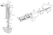
- FIG. 1is a perspective view of a guide wire retaining driver constructed in accordance with the various embodiments of the present invention
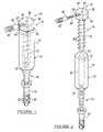
- FIG. 2is an exploded perspective view of the driver of FIG. 1 showing a driver member, a follower member, a guide wire clasping device, and an engaging member;
- FIG. 3is a cross section of the driver of FIG. 1 showing an internal pathway of a guide wire through the driver, which is shown slightly inserted into a material, such as a bone;
- FIG. 4is a perspective view of the guide wire inserted into the bone
- FIG. 5is a perspective view of a cannulated bone screw inserted over the guide wire, both of which are slightly inserted into the bone;
- FIG. 6is a perspective view of the guide wire retaining driver of FIG. 1 inserted over the guide wire and engaged to the bone screw;
- FIG. 7is a perspective view of the guide wire retaining driver of FIG. 6 showing a thumbscrew inserted into a guide wire clasping device to retain the guide wire;
- FIG. 8is a perspective view of the guide wire clasping device of FIG. 6 showing rotation of the driver member and insertion of the bone screw, while the follower member remains in a neutral position;
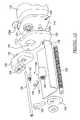
- FIG. 9is a side view of the guide wire retaining driver constructed in accordance with the various embodiments of the present invention showing a modified powered driver member, and engaging member, and a guide wire clasping rear assembly;
- FIG. 10is a rear view of the modified powered driver member showing a rear mounting plate that connects with the rear assembly;
- FIG. 11is a perspective view of the rear assembly showing a gearbox, a lead screw, and a guide wire clasping device;
- FIG. 12is an exploded perspective view of the rear assembly of FIG. 11 ;
- FIG. 13is a detailed view of the engaging member showing the guide wire through the engaging member and the bone screw;
- FIG. 14is a perspective view of the guide wire retaining driver of FIG. 9 showing the driver inserting the bone screw while maintaining the guide wire at a neutral position;
- FIG. 15is a detailed view of three exemplary lead screws and three exemplary bone screws.
- FIG. 16is a detailed view of a pitch of the threads of the lead screw and the bone screw.
- a guide wire retaining driveris shown generally indicated by reference numeral 10 .
- the driver 10includes a driver member generally indicated by reference numeral 12 and a follower member generally indicated by reference numeral 14 .
- An engaging member which is connected to the driver member 12is generally indicated by reference numeral 16 .
- the driver member 12includes a handle portion 18 that can be used to manually rotate the driver member 12 which rotates the engaging member 16 .
- the handle portion 18can have flutings, knurled surfaces, or the like, which provide more traction for manual actuation.
- the driver member 12also includes an internal bore 20 that includes a driver threaded portion 22 throughout at least a portion of the internal bore 20 .
- the driver threaded portion 22is configured to accept the follower member 14 , so that the follower member 14 can be rotated into and thus at least partially disposed within the driver member 12 .
- the driver member 12includes an engaging member connection point 24 .
- the engaging member 16is shown connected to driver member 12 at the engaging member connection point 24 .
- FIG. 2the engaging member 16 shown detached from the driver member 12 .
- the engaging member 16can be configured to fixedly connect to the driver member 12 , or be releasably attached. As such, the engaging member 16 can be press fit into the driver member 12 , or other suitable locking mechanism such as mechanical threads or chemical bonding may be used.
- the engaging member 16can be configured to engage conventional fasteners 26 with conventional heads, such as a six-sided hex-head, as shown in FIG. 2 . It will be appreciated that many different heads may be used either on the engaging member 16 or on the conventional fasteners 26 , such as Philips, hex, Torx®, slotted, or the like. Other heads may include one-direction engagement heads that only allow the engaging member 16 to insert the conventional fasteners 26 but not remove it. Other heads may use break away heads as are known in the art. Other suitable bone fixation systems and methods of use thereof are disclosed in commonly assigned U.S. Pat. Nos. 6,022,352 and 5,810,821, both to Vandewalle, issued Feb. 8, 2000 and Sep. 22, 1998 respectively, which are hereby incorporated by reference as if fully set forth herein.
- the conventional fastener 26can be a modified conventional bone screw or other such threaded fastener that is configured with a suitable head to engage with the engaging member 16 . It will be appreciated that not only is the conventional fastener 26 cannulated, the driver member 12 , the follower member 14 , and the engaging member 16 are cannulated as well. It will also be appreciated that the driver 10 may insert other medical devices with which the engaging member can be configured to connect. Other exemplary engaging members and fasteners are disclosed in commonly assigned U.S. Pat. No. 6,402,757 issued Jun. 11, 2002, which is hereby incorporate by reference as if fully set forth herein.
- the conventional fasteners 26have a fastener threaded portion 30 with a device thread pitch 32 .
- the fastener 26is inserted into a material at a certain depth per rotation. More specifically, fasteners 26 with a dense device thread pitch 32 will have a smaller insertion rate per rotation when compared to fasteners 26 with a larger device thread pitch 32 (i.e. less threads per inch).
- the follower member 14includes a threaded portion 34 having an instrument thread pitch 36 .
- the follower member 14can be configured to be threaded into the internal bore 20 of the driver member 12 . While the follower member 14 can be threaded completely into the driver member 12 or completely removed therefrom, the follower member 14 remains rotateably movable throughout a plurality of positions in the driver member 12 .
- the cannulated follower member 14can be configured to remain coaxial with the cannulated driver member 12 , the engaging member 16 , and, if applicable, the fastener 26 throughout the plurality of positions in the driver member 12 .
- the follower member 14includes a clasping device 38 connected to the following member at an end 40 distal from an insertion end 42 , which is configured to insert into the member driver 12 .
- the clasping device 38like the follower member 14 , is cannulated so that a guide wire 44 ( FIG. 3 ) can be inserted into the clasping device 38 and through the follower member 14 .
- the clasping device 38can be configured to fixedly attach to the end 40 of the follower member 14 .
- the clasping device 38can also be releasably attached to the follower member 14 , which allows varying threaded portions 34 to be attached to a single clasping device 38 .
- the clasping device 38may be attached to the follower member 14 using a press fit, a snap fit, a threaded connection, or some other suitable releasable connection.
- An exemplary guide wireis disclosed in commonly assigned U.S. Pat. No. 6,402,757 already incorporated by reference.
- a thumbscrew 46can be connected to the clasping device 38 .
- the thumbscrew 46can be configured to be threaded into the clasping device 38 , such that tightening the thumbscrew 46 secures the guide wire 44 within the clasping device 38 , as shown in FIG. 3 .
- the thumbscrew 46may be configured in different ways to ultimately apply a force against the guide wire 44 ( FIG. 3 ) to secure it within the clasping device 38 or any other clasping device 38 may be used to secure the guide wire 44 .
- the thumbscrew 46has a knurled portion 48 and a thumbscrew threaded portion 50 .
- the clasping device 38has a threaded aperture 52 configured to receive the thumbscrew threaded portion 50 .
- the threaded aperture 52is open to an exterior surface 54 and a clasping device internal bore 56 . As such, a user (not shown) can rotate the thumbscrew 46 into the threaded aperture 52 and secure the thumbscrew 46 against the guide wire 44 in the clasping device 38 .
- the guide wire 44is shown inserted through the cannulated driver 10 .
- the thumbscrew 46is shown tightened against the guide wire 44 , thus securing it within the follower member 14 .
- the driver 10is shown connected to a fastener 26 positioned over the guide wire 44 both of which are partially inserted into bone material 58 .
- the guide wire 44is shown partially inserted into an exemplary femoral section 60 .
- the guide wire retaining driver 10can be used with various bones, or for the specific use of affixing femoral neck fractures. It will nevertheless be appreciated that the driver 10 can be used with various bones of the human body or other applicable skeletal structures. It will also be appreciated that the driver 10 may be used outside the realm of medical devices to assist in affixing at least two pieces of material together. If used in such a non-medical environment, some characteristics that rendered the driver 10 suitable for use with medical devices need not be implemented on the driver 10 outside the medical realm.
- Insertion of the guide wire 44 into the femoral section 60is an exemplary step in the method of using the driver 10 .
- a small cavity 62is prepared in the femoral section 60 using a drilling device, or the driver 10 outfitted with a drill member (not shown).
- the guide wire 44is inserted into the cavity 62 .
- the guide wire 44may be configured with a burr (not shown), which allows a user (not shown) to create the cavity 62 using the guide wire 44 in lieu of, or along with, the drilling device.
- the fastener 26is shown initially positioned over the guide wire 44 and slightly inserted into the femoral section 60 , as shown in FIG. 5 .
- the driver 10is then inserted over the guide wire 44 and engaged with the fastener 26 , as shown in FIG. 6 .
- the thumbscrew 46is then inserted into the clasping devices 38 and secured against the guide wire 44 , as shown in FIG. 7 .
- a progression from FIG. 4 through FIG. 7illustrates a method of use of the driver 10 .
- the driver 10can be set up in many different ways, such that the driver 10 and the fastener 26 in combination can be positioned over the guide wire 44 .
- the guide wire 44need not be used with the driver 10 , such that the fastener 26 can be inserted without the guidance of the guide wire 44 .
- the driver member 12is shown being rotated in a clockwise motion, as noted by reference numeral 64 . It will be appreciated as the driver member 12 rotates the fastener 26 is driven deeper into the femoral section 60 . As the fastener 26 progresses deeper into the femoral section 60 , the driver member 12 rotates around the threaded portion 34 of the follower member 14 . It will be appreciated that the follower member 14 can remain in the same position, as the driver member 12 rotates the fastener 26 deeper into the femoral section 60 . Because the follower member 14 remains in the same position, the guide wire 44 neither rotates nor moves axially with the driver member 12 as it inserts the fastener 26 .
- the fastener 26has the threaded portion 30 with the device thread pitch 32 .
- the follower member 14also has a threaded portion 34 with an instrument thread pitch 36 . If the device thread pitch 32 is about equal to the instrument thread pitch 36 , the distance between clasping device 38 and the driver member 12 will be about equal to the distance the fastener 26 has been driven into the femoral section 60 . More specifically, an insertion rate of the fastener 26 will be about equal to an extraction rate of the guide wire 44 . If you insert the fastener about one inch (about 2.5 centimeters), therefore, the guide wire 44 will be extracted about one inch (about 2.5 centimeters), which maintains the guide wire 44 at its initial or neutral position. With the two thread pitches 32 and 36 equal, the follower member 14 will not translate axially, with respect to its initial position, so that the guide wire 44 neither rotates nor moves axially, thereby preventing the guide wire 44 from being driven deeper into the patient.
- the follower member 14can translate axially either away from or toward the fastener 26 .
- the extraction rate of the guide wire 44can be altered to be greater or less than the insertion rate of the fastener 26 .
- the follower member 14can be altered to translate toward the driver member 12 as the driver member 12 inserts the fastener 26 , except that the follower member 14 would need to be at least partially extended from the driver member 12 as shown in FIG. 8 .
- a guide wire retaining driveris shown constructed in accordance with various embodiments of the present invention and generally indicated by reference numeral 100 . It will be appreciated that the driver 100 can also maintain the guide wire 44 ( FIG. 8 ) so that it neither rotates nor moves axially with respect to the guide wire 44 . To that end, the driver 100 includes a modified conventional power driver generally indicated by reference numeral 102 . The power driver 102 is connected to a driver member and a rear assembly generally indicated by reference numerals 104 and 106 , respectively.
- the power driver 102is cannulated so that the guide wire 108 ( FIGS. 13 and 14 ), similar if not identical to the guide wire 44 , can be positioned through the driver member 104 , the power driver 102 , and the rear assembly 106 . It will be further appreciated that there are many suitable power drivers available that are both cannulated and suitable as a medical device.
- One exemplary modifiable power driveris commercially available from Aesculap® (Center Valley, Pa.) under the trade name Acculan® drill.
- the powered driver 102includes a modified backplate 110 connected to a rechargeable driver body 112 .
- the rechargeable driver body 112has speed and direction controls 114 and a battery cap 116 .
- the direction controls 114are configured so that the driver body 112 can operate in forward and in reverse and at variable speeds commensurate with the position of the direction controls 114 .
- the battery cap 116secures a rechargeable battery (not shown) within the driver body 112 .
- the modified backplate 110connects to a rear portion 118 of the driver body 112 .
- the modified backplate 110includes the first post 120 a and a second post 120 b , collectively referred to hereinafter as rear posts 120 .
- the modified backplate 110also includes an engaging wheel 122 that is coaxial with the driving member 104 .
- the modified backplate 110can be connected to the rear portion 118 of the driver body 112 with suitable mechanical fasteners 124 , or other such suitable forms of bonding such as but not limited to welding or adhesives.
- the rear assembly 106connects to the modified backplate 110 by placing a mounting plate 126 of the rear assembly 106 in line with the modified backplate 110 and abutting it at a slightly canted angle.
- the mounting plate 126is shown slightly canted angle such that the connector plate 126 is canted counterclockwise with respect to the to the backplate 110 .
- the rear assembly 106is rotated clockwise into vertical alignment with respect to the backplate 110 .
- the mounting plate 126locks into the rear posts 120 of the power driver 102 .
- the rear assembly 106includes an assembly pan 128 connected to a drivetrain 130 .
- a lead screw 132connects the drivetrain 130 to a rear bracket 134 .
- a shaft 136connects a flange 138 to the mounting plate 126 .
- Both the drivetrain 130 and the assembly pan 128are connected to the mounting plate 126 .
- the rear bracket 134 and the flange 138are connected to the assembly pan 128 at a location distal to the drivetrain 130 .
- a guide wire clasping device 140is rotateably engaged to the lead screw 132 and coupled with the shaft 136 .
- the drivetrain 130is connected to the mounting plate 126 so that a drive wheel 131 is disposed in a mounting plate aperture 141 ( FIG. 12 ).
- the drive wheel 131connects with the engaging wheel 122 thereby delivering rotational power from the power driver 102 to the drivetrain 130 .
- the drivetrainrotateably connects the engaging wheel 122 to the lead screw 132 so that rotation of the engaging wheel 122 rotates the lead screw 132 .
- there is no gear reduction in the drivetrain 130such that the engaging wheel 122 rotates at the same speed as the lead screw 132 .
- the drivetrain 130can incorporate additional gearing so that the lead screw 132 is rotated at different but proportional speed to the driver 102 .
- the drivetrain 130can be configured where the gear ratio is adjustable and the ratio of driver 102 rotation speed to lead screw 132 rotation speeds can be altered in situ.
- the guide wire clasping device 140includes a setscrew 142 , a lead screw channel 144 , and a shaft follower 146 .
- a guide wire pass-through 148is below the setscrew 142 .
- the guide wire 108( FIG. 14 ) is passed through a guide wire aperture 150 in the drivetrain 130 and then through the guide wire pass-through 148 in the guide wire clasping device 140 .
- the setscrew 142is rotated into the guide wire clasping device 140 to secure the guide wire 108 .
- the guide wire 108With the guide wire 108 secured in the guide wire clasping device 140 , the guide wire 108 will move with the guide wire clasping device 140 when the lead screw 132 rotates. As such, the power driver 102 rotates, which drives the drivetrain 130 that, in turn, rotates the lead screw 132 .
- the lead screw channel 144is configured so that the guide wire clasping device 140 translates away from the driver 102 as the driver 102 drives the fastener 152 into a bone 154 , as depicted in FIG. 14 .
- the driver member of the driver 100includes a removable modified chuck 156 and an engaging member 158 that is configured to engage various fasteners 152 , of fasteners 26 as discussed above.
- the chuck 156is a modified chuck an example of which is commercially available from Jacobson® through various commercial vendors. Attached to the rear portion of the chuck 156 is a mounting sleeve 160 that mounts the chuck 156 to the power driver 102 . Pushing a mounting sleeve lip 162 , away from the power driver 102 , will detach the chuck 156 and the mounting sleeve 160 from the power driver 102 .
- the chuck 156can be attached to the mounting sleeve 160 with mechanical threads 164 or other forms of suitable bonding. As such, the chuck 156 and the mounting sleeve 160 may be releasably attached to the power driver 102 or fixedly attached.
- the components of the driver 100are assembled and used to insert a fastener 152 into the bone 154 .
- the guide wire 108is inserted into the bone 154 .
- a cavity 164can be created in the bone 154 prior to insertion of the guide 108 , or can be created with the guide wire 108 , as discussed above, with reference to the guide wire 44 .
- the fastener 152is positioned over the guide wire 108 .
- the driver 100is positioned over the guide wire 108 and engaged to the fastener 152 .
- the guide wire 108is locked in the guide wire clasping device 140 with the setscrew 142 .
- the guide wire clasping device 140is configured to maintain the guide wire at its initial position so that the guide wire 108 neither rotates nor translates axially with respect to its initial position. It will be appreciated that once the guide wire clasping device 140 reaches either end of the lead screw 132 , the lead screw channel is disengaged with the lead screw 132 . The lead screw channel 144 can also be manually disengaged from the lead screw 132 and move about the lead screw 132 .
- the driver 100is configured so that the extraction rate of the guide wire 108 is about equal to the insertion rate of the fastener 152 .
- the extraction rate of the guide wirerefers to the movement of the guide wire clasping device 140 so that it maintains the guide wire 108 in its initial position. It will be appreciated that as the fastener 152 is inserted the guide wire 108 does not continue in deeper with the guide wire 108 , but remains in its initial position. In this case, the extraction rate and the insertion rates are equal.
- multiple lead screws 132are shown along with multiple fasteners 152 . If the drivetrain 130 has no gear reduction and the extraction rate and the insertion rate are about equal, a fastener thread pitch 166 and a lead screw thread pitch 168 are about equal. As discussed above, it will be appreciated that altering the fastener or lead screw thread pitch 166 and 168 can alter the extraction rate when compared to the insertion rate of the fastener 152 . The drivetrain 130 gearing can also be altered to produce the same effect. It follows therefore that many lead screws and many fasteners are available with the driver 100 so that extraction rates and insertion rates can be matched or mismatched accordingly.
Landscapes
- Health & Medical Sciences (AREA)
- Life Sciences & Earth Sciences (AREA)
- Orthopedic Medicine & Surgery (AREA)
- Surgery (AREA)
- Biomedical Technology (AREA)
- Engineering & Computer Science (AREA)
- Nuclear Medicine, Radiotherapy & Molecular Imaging (AREA)
- Heart & Thoracic Surgery (AREA)
- Medical Informatics (AREA)
- Molecular Biology (AREA)
- Animal Behavior & Ethology (AREA)
- General Health & Medical Sciences (AREA)
- Public Health (AREA)
- Veterinary Medicine (AREA)
- Surgical Instruments (AREA)
Abstract
Description
Claims (10)
Priority Applications (2)
| Application Number | Priority Date | Filing Date | Title |
|---|---|---|---|
| US10/767,619US7207995B1 (en) | 2004-01-29 | 2004-01-29 | Method and apparatus for retaining a guide wire |
| US11/684,800US8715293B2 (en) | 2004-01-29 | 2007-03-12 | Method and apparatus for retaining a guide wire |
Applications Claiming Priority (1)
| Application Number | Priority Date | Filing Date | Title |
|---|---|---|---|
| US10/767,619US7207995B1 (en) | 2004-01-29 | 2004-01-29 | Method and apparatus for retaining a guide wire |
Related Child Applications (1)
| Application Number | Title | Priority Date | Filing Date |
|---|---|---|---|
| US11/684,800DivisionUS8715293B2 (en) | 2004-01-29 | 2007-03-12 | Method and apparatus for retaining a guide wire |
Publications (1)
| Publication Number | Publication Date |
|---|---|
| US7207995B1true US7207995B1 (en) | 2007-04-24 |
Family
ID=37950753
Family Applications (2)
| Application Number | Title | Priority Date | Filing Date |
|---|---|---|---|
| US10/767,619Expired - Fee RelatedUS7207995B1 (en) | 2004-01-29 | 2004-01-29 | Method and apparatus for retaining a guide wire |
| US11/684,800Expired - Fee RelatedUS8715293B2 (en) | 2004-01-29 | 2007-03-12 | Method and apparatus for retaining a guide wire |
Family Applications After (1)
| Application Number | Title | Priority Date | Filing Date |
|---|---|---|---|
| US11/684,800Expired - Fee RelatedUS8715293B2 (en) | 2004-01-29 | 2007-03-12 | Method and apparatus for retaining a guide wire |
Country Status (1)
| Country | Link |
|---|---|
| US (2) | US7207995B1 (en) |
Cited By (70)
| Publication number | Priority date | Publication date | Assignee | Title |
|---|---|---|---|---|
| US20060111729A1 (en)* | 2004-11-23 | 2006-05-25 | Arthrotek, Inc. | Method and apparatus for manipulating bone during a surgical procedure |
| US20060195104A1 (en)* | 2003-08-08 | 2006-08-31 | Christoph Schlafli | Clamping device |
| US20060241619A1 (en)* | 2005-04-20 | 2006-10-26 | Daniel Cerundolo | Method and apparatus for surgical repair |
| US20070038034A1 (en)* | 2005-08-15 | 2007-02-15 | Sweeney Thomas M Ii | Systems and methods for performing percutaneous surgery |
| US20070118146A1 (en)* | 2005-11-23 | 2007-05-24 | Stryker Trauma S.A. | Compression instrument |
| US20070213736A1 (en)* | 2006-03-07 | 2007-09-13 | Dustin Ducharme | Countersink for use in orthopedic surgery |
| US20080015632A1 (en)* | 2006-07-14 | 2008-01-17 | Stryker Trauma Gmbh | Device, kit, and a method for handling a medical implant |
| US20080147128A1 (en)* | 2006-12-15 | 2008-06-19 | Zimmer Technology, Inc. | Cannulated bone screw and cannulated driver for the implantation thereof |
| US20080228195A1 (en)* | 2007-03-15 | 2008-09-18 | General Electric Company | Instrument guide for use with a surgical navigation system |
| US20080243133A1 (en)* | 2007-02-27 | 2008-10-02 | Warsaw Orthopedic, Inc. | Surgical Driver |
| US20080269768A1 (en)* | 2007-04-10 | 2008-10-30 | Stryker Trauma Sa | Bone screw holding device |
| US20090248029A1 (en)* | 2008-03-31 | 2009-10-01 | Lonnie Paulos | Interference screw driver assembly and method of use |
| US20100030221A1 (en)* | 2008-08-04 | 2010-02-04 | Georg Christian | Clamping sleeve for clamping a cannulated drill and a guide wire |
| ITMI20081592A1 (en)* | 2008-09-08 | 2010-03-09 | Lorenzo Maria Cecconello | INTERFRAMMENTARY COMPRESSION AND BLOCKING OF A KIRSCHNER WIRE, PARTICULARLY FOR SYNTHESIS OF BONE FRACTURES |
| GB2463522A (en)* | 2008-09-17 | 2010-03-24 | Martin Philcox | Controlled feed reamer and single pass cutter |
| US20100241124A1 (en)* | 2009-03-18 | 2010-09-23 | Smith & Nephew, Inc. | Soft Tissue Manipulator Assembly |
| US20120059480A1 (en)* | 2010-03-22 | 2012-03-08 | Amendia, Inc. | Percutaneous arthrodesis method and system |
| WO2013090392A1 (en)* | 2011-12-12 | 2013-06-20 | Extremity Medical, Llc | Devices and methods for bone fixation using axial implants |
| US20130304068A1 (en)* | 2010-12-13 | 2013-11-14 | D.L.P. | Surgical instrument for a technique for attaching bone fragments using a cannulated screw |
| US20130310842A1 (en)* | 2012-05-15 | 2013-11-21 | Tobias Winkler | Installation tool for bone screw |
| US20140031830A1 (en)* | 2012-07-24 | 2014-01-30 | Paradigm Spine, Llc | Bone fastener assembly instrument |
| US8641717B2 (en) | 2010-07-01 | 2014-02-04 | DePuy Synthes Products, LLC | Guidewire insertion methods and devices |
| US20140094822A1 (en)* | 2012-09-21 | 2014-04-03 | Atlas Spine, Inc. | Minimally invasive spine surgery instruments: guide wire handle with a guide wire locking mechanism |
| US8784429B2 (en) | 2011-01-11 | 2014-07-22 | Jason A. Bryan | Distance indicator |
| WO2014125328A1 (en) | 2013-02-13 | 2014-08-21 | DePuy Synthes Products, LLC. | Pedicle screw engaging control instrument with a guidewire capturing system |
| US20140257391A1 (en)* | 2004-04-20 | 2014-09-11 | James L. Chappuis | Internal Pedicle Insulator Apparatus and Method of Use |
| US20140276892A1 (en)* | 2013-03-14 | 2014-09-18 | Aesculap Implant Systems, Llc | Driver assembly with guidewire control mechanism |
| US20160030100A1 (en)* | 2014-08-04 | 2016-02-04 | DePuy Synthes Products, LLC | Methods and Devices for Spinal Screw Insertion |
| US9289249B2 (en) | 2013-03-14 | 2016-03-22 | DePuy Synthes Products, Inc. | Bone anchors and surgical instruments with integrated guide tips |
| US9427274B1 (en) | 2013-10-17 | 2016-08-30 | Z'egist Solutions, LLC | Surgical cutting system and method |
| US10080583B2 (en) | 2014-12-12 | 2018-09-25 | Depuy Mitel, Llc | Dilator for accessing a joint space |
| US20180368893A1 (en)* | 2017-06-27 | 2018-12-27 | Medos International Sarl | Spinal Screw Insertion Devices and Methods |
| EP3517069A1 (en)* | 2018-01-29 | 2019-07-31 | Globus Medical, Inc. | Surgical robotic automation with tracking markers |
| US10624710B2 (en) | 2012-06-21 | 2020-04-21 | Globus Medical, Inc. | System and method for measuring depth of instrumentation |
| US10646280B2 (en) | 2012-06-21 | 2020-05-12 | Globus Medical, Inc. | System and method for surgical tool insertion using multiaxis force and moment feedback |
| US10758315B2 (en) | 2012-06-21 | 2020-09-01 | Globus Medical Inc. | Method and system for improving 2D-3D registration convergence |
| US10779872B2 (en) | 2017-11-02 | 2020-09-22 | Medos International Sarl | Bone anchor insertion instruments and methods |
| US10799298B2 (en) | 2012-06-21 | 2020-10-13 | Globus Medical Inc. | Robotic fluoroscopic navigation |
| US10842461B2 (en) | 2012-06-21 | 2020-11-24 | Globus Medical, Inc. | Systems and methods of checking registrations for surgical systems |
| US10874466B2 (en) | 2012-06-21 | 2020-12-29 | Globus Medical, Inc. | System and method for surgical tool insertion using multiaxis force and moment feedback |
| US11045267B2 (en) | 2012-06-21 | 2021-06-29 | Globus Medical, Inc. | Surgical robotic automation with tracking markers |
| EP3861941A1 (en)* | 2020-02-06 | 2021-08-11 | Aesculap AG | Bone screw driver assembly |
| US11123113B2 (en) | 2019-06-13 | 2021-09-21 | Medos International Sarl | Screw inserter instruments and methods |
| US11224472B2 (en)* | 2019-06-13 | 2022-01-18 | Medos International Sarl | Screw inserter instruments and methods |
| US11253327B2 (en) | 2012-06-21 | 2022-02-22 | Globus Medical, Inc. | Systems and methods for automatically changing an end-effector on a surgical robot |
| US11298196B2 (en) | 2012-06-21 | 2022-04-12 | Globus Medical Inc. | Surgical robotic automation with tracking markers and controlled tool advancement |
| US11317971B2 (en) | 2012-06-21 | 2022-05-03 | Globus Medical, Inc. | Systems and methods related to robotic guidance in surgery |
| US11399900B2 (en) | 2012-06-21 | 2022-08-02 | Globus Medical, Inc. | Robotic systems providing co-registration using natural fiducials and related methods |
| US20220240919A1 (en)* | 2019-07-02 | 2022-08-04 | Conmed Corporation | Automated anchor insertion system |
| US11432860B2 (en)* | 2018-07-30 | 2022-09-06 | OSO Extremity, Inc. | Bone fixation system |
| US20220378488A1 (en)* | 2018-09-24 | 2022-12-01 | Astura Medical Inc. | Stylet screw driver |
| US11589771B2 (en) | 2012-06-21 | 2023-02-28 | Globus Medical Inc. | Method for recording probe movement and determining an extent of matter removed |
| US11633223B2 (en)* | 2018-12-20 | 2023-04-25 | Integrity Implants Inc. | Surgical guidance device |
| US11707284B2 (en) | 2019-03-06 | 2023-07-25 | K2M, Inc. | Bone screws, instrumentation, and methods of using of same |
| US20230320771A1 (en)* | 2022-04-11 | 2023-10-12 | Spineology Inc. | Surgical screwdriver system |
| US11786324B2 (en) | 2012-06-21 | 2023-10-17 | Globus Medical, Inc. | Surgical robotic automation with tracking markers |
| US11793570B2 (en) | 2012-06-21 | 2023-10-24 | Globus Medical Inc. | Surgical robotic automation with tracking markers |
| US11857149B2 (en) | 2012-06-21 | 2024-01-02 | Globus Medical, Inc. | Surgical robotic systems with target trajectory deviation monitoring and related methods |
| US11857266B2 (en) | 2012-06-21 | 2024-01-02 | Globus Medical, Inc. | System for a surveillance marker in robotic-assisted surgery |
| US11864745B2 (en) | 2012-06-21 | 2024-01-09 | Globus Medical, Inc. | Surgical robotic system with retractor |
| US11864839B2 (en) | 2012-06-21 | 2024-01-09 | Globus Medical Inc. | Methods of adjusting a virtual implant and related surgical navigation systems |
| US11883217B2 (en) | 2016-02-03 | 2024-01-30 | Globus Medical, Inc. | Portable medical imaging system and method |
| US11896446B2 (en) | 2012-06-21 | 2024-02-13 | Globus Medical, Inc | Surgical robotic automation with tracking markers |
| US11963755B2 (en) | 2012-06-21 | 2024-04-23 | Globus Medical Inc. | Apparatus for recording probe movement |
| US11974822B2 (en) | 2012-06-21 | 2024-05-07 | Globus Medical Inc. | Method for a surveillance marker in robotic-assisted surgery |
| US12004905B2 (en) | 2012-06-21 | 2024-06-11 | Globus Medical, Inc. | Medical imaging systems using robotic actuators and related methods |
| US20240252215A1 (en)* | 2023-01-31 | 2024-08-01 | Orthofix Us Llc | Targeting and insertion instrument for orthopedic implants |
| US12133699B2 (en) | 2012-06-21 | 2024-11-05 | Globus Medical, Inc. | System and method for surgical tool insertion using multiaxis force and moment feedback |
| US12150728B2 (en) | 2021-04-14 | 2024-11-26 | Globus Medical, Inc. | End effector for a surgical robot |
| US12329418B2 (en) | 2022-07-26 | 2025-06-17 | Globus Medical Inc. | Minimally invasive surgery guide wire capturing instrumentation |
Families Citing this family (15)
| Publication number | Priority date | Publication date | Assignee | Title |
|---|---|---|---|---|
| WO2007121271A2 (en) | 2006-04-11 | 2007-10-25 | Synthes (U.S.A) | Minimally invasive fixation system |
| CN102497828B (en) | 2009-05-20 | 2015-09-09 | 斯恩蒂斯有限公司 | What patient installed retracts part |
| US9265622B2 (en) | 2010-03-22 | 2016-02-23 | Amendia, Inc. | Percutaneous arthrodesis method and system |
| US8535318B2 (en) | 2010-04-23 | 2013-09-17 | DePuy Synthes Products, LLC | Minimally invasive instrument set, devices and related methods |
| CN103717159B (en) | 2011-05-27 | 2016-08-17 | 新特斯有限责任公司 | Minimally Invasive Spinal Fixation System Including Vertebral Alignment Features |
| US10070873B2 (en)* | 2014-06-30 | 2018-09-11 | Tornier, Inc. | Device for maintaining alignment of a cannulated shaft over a guide pin |
| US10357314B2 (en) | 2015-07-08 | 2019-07-23 | Stryker European Holdings I, Llc | Instrumentation and method for repair of a bone fracture |
| US10973558B2 (en) | 2017-06-12 | 2021-04-13 | K2M, Inc. | Screw insertion instrument and methods of use |
| US11344353B2 (en)* | 2018-12-20 | 2022-05-31 | Integrity Implants Inc. | Surgical guidance device and system for insertion thereof |
| KR102190053B1 (en)* | 2019-04-02 | 2020-12-11 | 연세대학교 산학협력단 | Clamp device for surgical guide wire |
| FR3106483B1 (en)* | 2020-01-25 | 2023-06-16 | Spinedust | Device to aid in the implantation of a bone screw in the bone environment of a living being. |
| EP4203812B1 (en)* | 2020-08-28 | 2024-10-09 | Nuvasive, Inc. | Ratchet retracting handles |
| US12262927B2 (en) | 2020-12-10 | 2025-04-01 | K2M, Inc. | Screw insertion instrument and methods of use |
| US12329423B2 (en)* | 2020-12-21 | 2025-06-17 | Nuvasive Inc. | Stylet control handles and methods of using the same |
| WO2023102423A1 (en)* | 2021-12-01 | 2023-06-08 | Foley Kevin T | Guidewire retention mechanism |
Citations (10)
| Publication number | Priority date | Publication date | Assignee | Title |
|---|---|---|---|---|
| US2243717A (en)* | 1938-09-20 | 1941-05-27 | Moreira Franciseo Elias Godoy | Surgical device |
| US2248054A (en) | 1939-06-07 | 1941-07-08 | Becker Joseph | Screw driver |
| US5257996A (en) | 1991-12-13 | 1993-11-02 | Mcguire David A | Surgical pin passer |
| US5391170A (en) | 1991-12-13 | 1995-02-21 | David A. McGuire | Angled surgical screw driver and methods of arthroscopic ligament reconstruction |
| US5429641A (en)* | 1993-03-28 | 1995-07-04 | Gotfried; Yechiel | Surgical device for connection of fractured bones |
| US5464407A (en) | 1991-02-19 | 1995-11-07 | Mcguire; David A. | Flexible surgical screwdriver and methods of arthroscopic ligament reconstruction |
| US5520693A (en) | 1992-02-19 | 1996-05-28 | Mcguire; David A. | Femoral guide and methods of precisely forming bone tunnels in cruciate ligament reconstruction of the knee |
| US5658289A (en) | 1993-09-24 | 1997-08-19 | Linvatec Corporation | Ligament graft protection apparatus and method |
| US5697935A (en)* | 1995-09-12 | 1997-12-16 | Medex Marketing, Inc. | Device and method for removing fastening implements from bone |
| US6827722B1 (en)* | 2001-12-11 | 2004-12-07 | Biomet, Inc. | Method and apparatus for use of a guide wire capturing surgical instrument |
Family Cites Families (9)
| Publication number | Priority date | Publication date | Assignee | Title |
|---|---|---|---|---|
| US2631584A (en)* | 1948-07-22 | 1953-03-17 | Alfred T Purificato | Fracture securing instrument |
| US3718340A (en)* | 1971-10-26 | 1973-02-27 | Stewart Research | Drill chuck |
| DE2621383A1 (en) | 1976-05-14 | 1977-12-01 | Gardner Denver Gmbh | METHOD OF PLACING IMPLANTS INTO BONE AND APPARATUS |
| DE3319149C1 (en) | 1983-05-26 | 1984-12-13 | Franz 7202 Mühlheim Leibinger | Arrangement for the mutual fixation of bone parts and tool for fastening this arrangement |
| US5139499A (en) | 1989-02-06 | 1992-08-18 | American Cyanamid Company | Screw and driver |
| US5129906A (en) | 1989-09-08 | 1992-07-14 | Linvatec Corporation | Bioabsorbable tack for joining bodily tissue and in vivo method and apparatus for deploying same |
| US5071420A (en) | 1991-04-25 | 1991-12-10 | Depuy Du Pont Orthopaedics | Isometry testing device |
| US5323765A (en) | 1991-12-03 | 1994-06-28 | Brown Michael G | Apparatus and method for endoscopic surgery |
| US6436100B1 (en) | 1998-08-07 | 2002-08-20 | J. Lee Berger | Cannulated internally threaded bone screw and reduction driver device |
- 2004
- 2004-01-29USUS10/767,619patent/US7207995B1/ennot_activeExpired - Fee Related
- 2007
- 2007-03-12USUS11/684,800patent/US8715293B2/ennot_activeExpired - Fee Related
Patent Citations (10)
| Publication number | Priority date | Publication date | Assignee | Title |
|---|---|---|---|---|
| US2243717A (en)* | 1938-09-20 | 1941-05-27 | Moreira Franciseo Elias Godoy | Surgical device |
| US2248054A (en) | 1939-06-07 | 1941-07-08 | Becker Joseph | Screw driver |
| US5464407A (en) | 1991-02-19 | 1995-11-07 | Mcguire; David A. | Flexible surgical screwdriver and methods of arthroscopic ligament reconstruction |
| US5257996A (en) | 1991-12-13 | 1993-11-02 | Mcguire David A | Surgical pin passer |
| US5391170A (en) | 1991-12-13 | 1995-02-21 | David A. McGuire | Angled surgical screw driver and methods of arthroscopic ligament reconstruction |
| US5520693A (en) | 1992-02-19 | 1996-05-28 | Mcguire; David A. | Femoral guide and methods of precisely forming bone tunnels in cruciate ligament reconstruction of the knee |
| US5429641A (en)* | 1993-03-28 | 1995-07-04 | Gotfried; Yechiel | Surgical device for connection of fractured bones |
| US5658289A (en) | 1993-09-24 | 1997-08-19 | Linvatec Corporation | Ligament graft protection apparatus and method |
| US5697935A (en)* | 1995-09-12 | 1997-12-16 | Medex Marketing, Inc. | Device and method for removing fastening implements from bone |
| US6827722B1 (en)* | 2001-12-11 | 2004-12-07 | Biomet, Inc. | Method and apparatus for use of a guide wire capturing surgical instrument |
Cited By (131)
| Publication number | Priority date | Publication date | Assignee | Title |
|---|---|---|---|---|
| US20060195104A1 (en)* | 2003-08-08 | 2006-08-31 | Christoph Schlafli | Clamping device |
| US8267974B2 (en)* | 2003-08-08 | 2012-09-18 | Synthes Usa, Llc | Clamping device |
| US20140257391A1 (en)* | 2004-04-20 | 2014-09-11 | James L. Chappuis | Internal Pedicle Insulator Apparatus and Method of Use |
| US9289242B2 (en)* | 2004-04-20 | 2016-03-22 | James L. Chappuis | Internal pedicle insulator apparatus and method of use |
| US20060111729A1 (en)* | 2004-11-23 | 2006-05-25 | Arthrotek, Inc. | Method and apparatus for manipulating bone during a surgical procedure |
| US7488323B2 (en)* | 2004-11-23 | 2009-02-10 | Biomet Sports Medicine, Llc | Method and apparatus for manipulating bone during a surgical procedure |
| US20060241619A1 (en)* | 2005-04-20 | 2006-10-26 | Daniel Cerundolo | Method and apparatus for surgical repair |
| US7569059B2 (en)* | 2005-04-20 | 2009-08-04 | Arthroscopic Innovations Llc | Method and apparatus for surgical repair |
| US20070038034A1 (en)* | 2005-08-15 | 2007-02-15 | Sweeney Thomas M Ii | Systems and methods for performing percutaneous surgery |
| US20070118146A1 (en)* | 2005-11-23 | 2007-05-24 | Stryker Trauma S.A. | Compression instrument |
| US7704257B2 (en)* | 2005-11-23 | 2010-04-27 | Stryker Trauma S.A. | Compression instrument |
| US20070213736A1 (en)* | 2006-03-07 | 2007-09-13 | Dustin Ducharme | Countersink for use in orthopedic surgery |
| US8029509B2 (en)* | 2006-03-07 | 2011-10-04 | Orthohelix Surgical Designs, Inc. | Countersink for use in orthopedic surgery |
| US8709014B2 (en)* | 2006-07-14 | 2014-04-29 | Stryker Trauma Gmbh | Device, kit, and a method for handling a medical implant |
| US20080015632A1 (en)* | 2006-07-14 | 2008-01-17 | Stryker Trauma Gmbh | Device, kit, and a method for handling a medical implant |
| US20080147128A1 (en)* | 2006-12-15 | 2008-06-19 | Zimmer Technology, Inc. | Cannulated bone screw and cannulated driver for the implantation thereof |
| US20080243133A1 (en)* | 2007-02-27 | 2008-10-02 | Warsaw Orthopedic, Inc. | Surgical Driver |
| US8845652B2 (en)* | 2007-02-27 | 2014-09-30 | Warsaw Orthopedic, Inc. | Surgical driver |
| US20080228195A1 (en)* | 2007-03-15 | 2008-09-18 | General Electric Company | Instrument guide for use with a surgical navigation system |
| US8821511B2 (en)* | 2007-03-15 | 2014-09-02 | General Electric Company | Instrument guide for use with a surgical navigation system |
| US20080269768A1 (en)* | 2007-04-10 | 2008-10-30 | Stryker Trauma Sa | Bone screw holding device |
| US20090248029A1 (en)* | 2008-03-31 | 2009-10-01 | Lonnie Paulos | Interference screw driver assembly and method of use |
| US8814935B2 (en) | 2008-03-31 | 2014-08-26 | The Lonnie and Shannon Paulos Trust | Interference screw driver assembly and method of use |
| US20100030221A1 (en)* | 2008-08-04 | 2010-02-04 | Georg Christian | Clamping sleeve for clamping a cannulated drill and a guide wire |
| EP2151202A1 (en) | 2008-08-04 | 2010-02-10 | BrainLAB AG | Clamping piece for clamping a cannulated drill and a guide wire |
| US8545510B2 (en) | 2008-08-04 | 2013-10-01 | Brainlab Ag | Clamping sleeve for clamping a cannulated drill and a guide wire |
| ITMI20081592A1 (en)* | 2008-09-08 | 2010-03-09 | Lorenzo Maria Cecconello | INTERFRAMMENTARY COMPRESSION AND BLOCKING OF A KIRSCHNER WIRE, PARTICULARLY FOR SYNTHESIS OF BONE FRACTURES |
| GB2463522B (en)* | 2008-09-17 | 2013-03-27 | Martin Philcox | Controlled feed surgical reamer |
| GB2463522A (en)* | 2008-09-17 | 2010-03-24 | Martin Philcox | Controlled feed reamer and single pass cutter |
| US20150173741A1 (en)* | 2009-03-18 | 2015-06-25 | Smith & Nephew, Inc. | Soft tissue repair method |
| US9060748B2 (en)* | 2009-03-18 | 2015-06-23 | Smith & Nephew, Inc. | Soft tissue manipulator assembly |
| US20100241124A1 (en)* | 2009-03-18 | 2010-09-23 | Smith & Nephew, Inc. | Soft Tissue Manipulator Assembly |
| US9480499B2 (en)* | 2009-03-18 | 2016-11-01 | Smith & Nephew, Inc. | Soft tissue repair method |
| US8496709B2 (en)* | 2010-03-22 | 2013-07-30 | Amendia, Inc | Spinal Implant |
| US20120059480A1 (en)* | 2010-03-22 | 2012-03-08 | Amendia, Inc. | Percutaneous arthrodesis method and system |
| US8641717B2 (en) | 2010-07-01 | 2014-02-04 | DePuy Synthes Products, LLC | Guidewire insertion methods and devices |
| US9186484B2 (en) | 2010-07-01 | 2015-11-17 | DePuy Synthes Products, Inc. | Guidewire insertion methods and devices |
| US20130304068A1 (en)* | 2010-12-13 | 2013-11-14 | D.L.P. | Surgical instrument for a technique for attaching bone fragments using a cannulated screw |
| US9131946B2 (en)* | 2010-12-13 | 2015-09-15 | D.L.P. | Surgical instrument for a technique for attaching bone fragments using a cannulated screw |
| US8784429B2 (en) | 2011-01-11 | 2014-07-22 | Jason A. Bryan | Distance indicator |
| WO2013090392A1 (en)* | 2011-12-12 | 2013-06-20 | Extremity Medical, Llc | Devices and methods for bone fixation using axial implants |
| US11197698B2 (en) | 2011-12-12 | 2021-12-14 | Extremity Medical, Llc | Devices and methods for bone fixation using axial implants |
| US12029456B2 (en) | 2011-12-12 | 2024-07-09 | Extremity Medical, Llc | Devices and methods for bone fixation using axial implants |
| US20130310842A1 (en)* | 2012-05-15 | 2013-11-21 | Tobias Winkler | Installation tool for bone screw |
| US10646280B2 (en) | 2012-06-21 | 2020-05-12 | Globus Medical, Inc. | System and method for surgical tool insertion using multiaxis force and moment feedback |
| US10842461B2 (en) | 2012-06-21 | 2020-11-24 | Globus Medical, Inc. | Systems and methods of checking registrations for surgical systems |
| US11317971B2 (en) | 2012-06-21 | 2022-05-03 | Globus Medical, Inc. | Systems and methods related to robotic guidance in surgery |
| US11298196B2 (en) | 2012-06-21 | 2022-04-12 | Globus Medical Inc. | Surgical robotic automation with tracking markers and controlled tool advancement |
| US12016645B2 (en) | 2012-06-21 | 2024-06-25 | Globus Medical Inc. | Surgical robotic automation with tracking markers |
| US12070285B2 (en) | 2012-06-21 | 2024-08-27 | Globus Medical, Inc. | Systems and methods for automatically changing an end-effector on a surgical robot |
| US12004905B2 (en) | 2012-06-21 | 2024-06-11 | Globus Medical, Inc. | Medical imaging systems using robotic actuators and related methods |
| US11974822B2 (en) | 2012-06-21 | 2024-05-07 | Globus Medical Inc. | Method for a surveillance marker in robotic-assisted surgery |
| US11963755B2 (en) | 2012-06-21 | 2024-04-23 | Globus Medical Inc. | Apparatus for recording probe movement |
| US11950865B2 (en) | 2012-06-21 | 2024-04-09 | Globus Medical Inc. | System and method for surgical tool insertion using multiaxis force and moment feedback |
| US12133699B2 (en) | 2012-06-21 | 2024-11-05 | Globus Medical, Inc. | System and method for surgical tool insertion using multiaxis force and moment feedback |
| US11253327B2 (en) | 2012-06-21 | 2022-02-22 | Globus Medical, Inc. | Systems and methods for automatically changing an end-effector on a surgical robot |
| US11911225B2 (en) | 2012-06-21 | 2024-02-27 | Globus Medical Inc. | Method and system for improving 2D-3D registration convergence |
| US11399900B2 (en) | 2012-06-21 | 2022-08-02 | Globus Medical, Inc. | Robotic systems providing co-registration using natural fiducials and related methods |
| US11589771B2 (en) | 2012-06-21 | 2023-02-28 | Globus Medical Inc. | Method for recording probe movement and determining an extent of matter removed |
| US11896446B2 (en) | 2012-06-21 | 2024-02-13 | Globus Medical, Inc | Surgical robotic automation with tracking markers |
| US11864839B2 (en) | 2012-06-21 | 2024-01-09 | Globus Medical Inc. | Methods of adjusting a virtual implant and related surgical navigation systems |
| US11786324B2 (en) | 2012-06-21 | 2023-10-17 | Globus Medical, Inc. | Surgical robotic automation with tracking markers |
| US11864745B2 (en) | 2012-06-21 | 2024-01-09 | Globus Medical, Inc. | Surgical robotic system with retractor |
| US11793570B2 (en) | 2012-06-21 | 2023-10-24 | Globus Medical Inc. | Surgical robotic automation with tracking markers |
| US11045267B2 (en) | 2012-06-21 | 2021-06-29 | Globus Medical, Inc. | Surgical robotic automation with tracking markers |
| US11857266B2 (en) | 2012-06-21 | 2024-01-02 | Globus Medical, Inc. | System for a surveillance marker in robotic-assisted surgery |
| US11857149B2 (en) | 2012-06-21 | 2024-01-02 | Globus Medical, Inc. | Surgical robotic systems with target trajectory deviation monitoring and related methods |
| US11819283B2 (en) | 2012-06-21 | 2023-11-21 | Globus Medical Inc. | Systems and methods related to robotic guidance in surgery |
| US10624710B2 (en) | 2012-06-21 | 2020-04-21 | Globus Medical, Inc. | System and method for measuring depth of instrumentation |
| US10874466B2 (en) | 2012-06-21 | 2020-12-29 | Globus Medical, Inc. | System and method for surgical tool insertion using multiaxis force and moment feedback |
| US10799298B2 (en) | 2012-06-21 | 2020-10-13 | Globus Medical Inc. | Robotic fluoroscopic navigation |
| US11819365B2 (en) | 2012-06-21 | 2023-11-21 | Globus Medical, Inc. | System and method for measuring depth of instrumentation |
| US10758315B2 (en) | 2012-06-21 | 2020-09-01 | Globus Medical Inc. | Method and system for improving 2D-3D registration convergence |
| US9173695B2 (en)* | 2012-07-24 | 2015-11-03 | Paradigm Spine, Llc | Bone fastener assembly instrument |
| US20140031830A1 (en)* | 2012-07-24 | 2014-01-30 | Paradigm Spine, Llc | Bone fastener assembly instrument |
| US10194967B2 (en)* | 2012-09-21 | 2019-02-05 | Atlas Spine, Inc. | Minimally invasive spine surgery instruments: guide wire handle with a guide wire locking mechanism |
| US20140094822A1 (en)* | 2012-09-21 | 2014-04-03 | Atlas Spine, Inc. | Minimally invasive spine surgery instruments: guide wire handle with a guide wire locking mechanism |
| US10709484B2 (en)* | 2013-02-13 | 2020-07-14 | DePuy Synthes Products, Inc. | Control instrument |
| CN105163681B (en)* | 2013-02-13 | 2020-06-30 | 新特斯有限责任公司 | Pedicle screw engagement control instrument with guidewire capture system |
| WO2014125328A1 (en) | 2013-02-13 | 2014-08-21 | DePuy Synthes Products, LLC. | Pedicle screw engaging control instrument with a guidewire capturing system |
| AU2018208641B2 (en)* | 2013-02-13 | 2019-09-12 | Synthes Gmbh | Pedicle screw engaging control instrument with a guidewire capturing system |
| US20180250037A1 (en)* | 2013-02-13 | 2018-09-06 | DePuy Synthes Products, Inc. | Control instrument |
| US9949770B2 (en)* | 2013-02-13 | 2018-04-24 | DePuy Synthes Products, Inc. | Pedicle screw engaging control instrument with a guidewire capturing system |
| US20170014165A1 (en)* | 2013-02-13 | 2017-01-19 | DePuy Snthers Products, Inc. | Pedicle screw engaging control instrument with a guidewire capturing system |
| CN105163681A (en)* | 2013-02-13 | 2015-12-16 | 新特斯有限责任公司 | Pedicle screw engaging control instrument with guidewire capturing system |
| US10413339B2 (en)* | 2013-03-14 | 2019-09-17 | DePuy Synthes Products, Inc. | Bone anchors and surgical instruments with integrated guide tips |
| US9289249B2 (en) | 2013-03-14 | 2016-03-22 | DePuy Synthes Products, Inc. | Bone anchors and surgical instruments with integrated guide tips |
| US11937857B2 (en) | 2013-03-14 | 2024-03-26 | DePuy Synthes Products, Inc. | Bone anchors and surgical instruments with integrated guide tips |
| US20140276892A1 (en)* | 2013-03-14 | 2014-09-18 | Aesculap Implant Systems, Llc | Driver assembly with guidewire control mechanism |
| US9433445B2 (en) | 2013-03-14 | 2016-09-06 | DePuy Synthes Products, Inc. | Bone anchors and surgical instruments with integrated guide tips |
| WO2014140132A1 (en)* | 2013-03-14 | 2014-09-18 | Aesculap Ag | Driver assembly with guidewire control mechanism |
| US11457961B2 (en) | 2013-03-14 | 2022-10-04 | DePuy Synthes Products, Inc. | Bone anchors and surgical instruments with integrated guide tips |
| US20160135856A1 (en)* | 2013-03-14 | 2016-05-19 | DePuy Synthes Products, Inc. | Bone anchors and surgical instruments with integrated guide tips |
| US9254160B2 (en)* | 2013-03-14 | 2016-02-09 | Aesculap Implant Systems, Llc | Driver assembly with guidewire control mechanism |
| US9427274B1 (en) | 2013-10-17 | 2016-08-30 | Z'egist Solutions, LLC | Surgical cutting system and method |
| US20200100824A1 (en)* | 2014-08-04 | 2020-04-02 | DePuy Synthes Products, Inc. | Methods and devices for spinal screw insertion |
| US20160030100A1 (en)* | 2014-08-04 | 2016-02-04 | DePuy Synthes Products, LLC | Methods and Devices for Spinal Screw Insertion |
| US11642158B2 (en)* | 2014-08-04 | 2023-05-09 | DePuy Synthes Products, Inc. | Methods and devices for spinal screw insertion |
| US20230233241A1 (en)* | 2014-08-04 | 2023-07-27 | DePuy Synthes Products, Inc. | Methods and devices for spinal screw insertion |
| US9855087B2 (en)* | 2014-08-04 | 2018-01-02 | DePuy Synthes Products, LLC | Methods and devices for spinal screw insertion |
| US10568677B2 (en) | 2014-08-04 | 2020-02-25 | DePuy Synthes Products, Inc. | Methods and devices for spinal screw insertion |
| US12089869B2 (en) | 2014-12-12 | 2024-09-17 | DePuy Synthes Products, Inc. | Dilator for accessing a joint space |
| US11266438B2 (en) | 2014-12-12 | 2022-03-08 | DePuy Synthes Products, Inc. | Dilator for accessing a joint space |
| US10080583B2 (en) | 2014-12-12 | 2018-09-25 | Depuy Mitel, Llc | Dilator for accessing a joint space |
| US11883217B2 (en) | 2016-02-03 | 2024-01-30 | Globus Medical, Inc. | Portable medical imaging system and method |
| US11648038B2 (en) | 2017-06-27 | 2023-05-16 | Medos International Sarl | Spinal screw insertion devices and methods |
| US10433883B2 (en)* | 2017-06-27 | 2019-10-08 | Medos International Sarl | Spinal screw insertion devices and methods |
| US20180368893A1 (en)* | 2017-06-27 | 2018-12-27 | Medos International Sarl | Spinal Screw Insertion Devices and Methods |
| US10779872B2 (en) | 2017-11-02 | 2020-09-22 | Medos International Sarl | Bone anchor insertion instruments and methods |
| EP3517069A1 (en)* | 2018-01-29 | 2019-07-31 | Globus Medical, Inc. | Surgical robotic automation with tracking markers |
| US11432860B2 (en)* | 2018-07-30 | 2022-09-06 | OSO Extremity, Inc. | Bone fixation system |
| US20220409252A1 (en)* | 2018-07-30 | 2022-12-29 | OSO Extremity, Inc. | Bone fixation system |
| US12232788B2 (en)* | 2018-07-30 | 2025-02-25 | OSO Extremity, Inc. | Bone fixation system |
| US11759246B2 (en)* | 2018-09-24 | 2023-09-19 | Astura Medical Inc | Stylet screw driver |
| US20220378488A1 (en)* | 2018-09-24 | 2022-12-01 | Astura Medical Inc. | Stylet screw driver |
| US20230293217A1 (en)* | 2018-12-20 | 2023-09-21 | Integrity Implants Inc. | Surgical guidance device |
| US11633223B2 (en)* | 2018-12-20 | 2023-04-25 | Integrity Implants Inc. | Surgical guidance device |
| US20250064497A1 (en)* | 2018-12-20 | 2025-02-27 | Integrity Implants Inc. | Surgical guidance device |
| US12042187B2 (en)* | 2018-12-20 | 2024-07-23 | Integrity Implants Inc. | Surgical guidance device |
| US11707284B2 (en) | 2019-03-06 | 2023-07-25 | K2M, Inc. | Bone screws, instrumentation, and methods of using of same |
| US20220110666A1 (en)* | 2019-06-13 | 2022-04-14 | Medos International Sarl | Screw inserter instruments and methods |
| US11123113B2 (en) | 2019-06-13 | 2021-09-21 | Medos International Sarl | Screw inserter instruments and methods |
| US11224472B2 (en)* | 2019-06-13 | 2022-01-18 | Medos International Sarl | Screw inserter instruments and methods |
| US12336746B2 (en)* | 2019-06-13 | 2025-06-24 | Medos International Sàrl | Screw inserter instruments and methods |
| US20220240919A1 (en)* | 2019-07-02 | 2022-08-04 | Conmed Corporation | Automated anchor insertion system |
| WO2021156396A1 (en)* | 2020-02-06 | 2021-08-12 | Aesculap Ag | Drill removal tool |
| EP3861941A1 (en)* | 2020-02-06 | 2021-08-11 | Aesculap AG | Bone screw driver assembly |
| US12150728B2 (en) | 2021-04-14 | 2024-11-26 | Globus Medical, Inc. | End effector for a surgical robot |
| US20230320771A1 (en)* | 2022-04-11 | 2023-10-12 | Spineology Inc. | Surgical screwdriver system |
| US12329418B2 (en) | 2022-07-26 | 2025-06-17 | Globus Medical Inc. | Minimally invasive surgery guide wire capturing instrumentation |
| US20240252215A1 (en)* | 2023-01-31 | 2024-08-01 | Orthofix Us Llc | Targeting and insertion instrument for orthopedic implants |
Also Published As
| Publication number | Publication date |
|---|---|
| US20070162046A1 (en) | 2007-07-12 |
| US8715293B2 (en) | 2014-05-06 |
Similar Documents
| Publication | Publication Date | Title |
|---|---|---|
| US7207995B1 (en) | Method and apparatus for retaining a guide wire | |
| JP4728322B2 (en) | Adjustable tool for fasteners cannulated | |
| US11771476B2 (en) | Apparatus and method for fenestrated screw augmentation | |
| EP2434973B1 (en) | Surgical instrument for fixing a clamp to a bone fixation device | |
| US8685067B2 (en) | Compression plate apparatus | |
| US8002812B2 (en) | Bone fixation implant system and method | |
| US20120109142A1 (en) | Surgical Screwdriver | |
| US9597135B1 (en) | Bone screw inserter | |
| US20100312292A1 (en) | Lagwire system and method for the fixation of bone fractures | |
| US11272962B2 (en) | Occipital fixation assembly, system and method for attaching the same | |
| EP1955667B1 (en) | Global nail screw retaining screwdriver | |
| US12226135B1 (en) | Surgical guide wire engagement device | |
| WO2012075128A2 (en) | Vertebral fixation system and methods of use |
Legal Events
| Date | Code | Title | Description |
|---|---|---|---|
| AS | Assignment | Owner name:BIOMET MANUFACTURING CORP., INDIANA Free format text:ASSIGNMENT OF ASSIGNORS INTEREST;ASSIGNOR:VANDEWALLE, MARK V.;REEL/FRAME:014946/0543 Effective date:20040128 | |
| STCF | Information on status: patent grant | Free format text:PATENTED CASE | |
| AS | Assignment | Owner name:EBI, L. P., NEW JERSEY Free format text:ASSIGNMENT OF ASSIGNORS INTEREST;ASSIGNOR:BIOMET MANUFACTURING CORP.;REEL/FRAME:019287/0368 Effective date:20070514 | |
| AS | Assignment | Owner name:BANK OF AMERICA, N.A., AS ADMINISTRATIVE AGENT FOR Free format text:SECURITY AGREEMENT;ASSIGNORS:LVB ACQUISITION, INC.;BIOMET, INC.;REEL/FRAME:020362/0001 Effective date:20070925 | |
| AS | Assignment | Owner name:EBI, LLC, NEW JERSEY Free format text:CHANGE OF NAME;ASSIGNOR:EBI, INC.;REEL/FRAME:021387/0450 Effective date:20080227 Owner name:EBI, LLC,NEW JERSEY Free format text:CHANGE OF NAME;ASSIGNOR:EBI, INC.;REEL/FRAME:021387/0450 Effective date:20080227 | |
| AS | Assignment | Owner name:EBI, LLC, NEW JERSEY Free format text:CORRECTIVE ASSIGNMENT TO CORRECT THE ASSIGNOR INCORRECTLY IDENTIFIED AS EBI, INC. ON ORIGINAL RECORDATION COVERSHEET SHOULD HAVE BEEN IDENTIFIED AS EBI, L.P. PREVIOUSLY RECORDED ON REEL 021387 FRAME 0450;ASSIGNOR:EBI, L.P.;REEL/FRAME:022727/0859 Effective date:20080227 Owner name:EBI, LLC,NEW JERSEY Free format text:CORRECTIVE ASSIGNMENT TO CORRECT THE ASSIGNOR INCORRECTLY IDENTIFIED AS EBI, INC. ON ORIGINAL RECORDATION COVERSHEET SHOULD HAVE BEEN IDENTIFIED AS EBI, L.P. PREVIOUSLY RECORDED ON REEL 021387 FRAME 0450. ASSIGNOR(S) HEREBY CONFIRMS THE ORIGINAL CONVEYANCE TEXT APPEARING IN NAME CHANGE DOCUMENTATION REFLECTS EBI, L.P. IS NOW KNOWN AS EBI, LLC.;ASSIGNOR:EBI, L.P.;REEL/FRAME:022727/0859 Effective date:20080227 Owner name:EBI, LLC, NEW JERSEY Free format text:CORRECTIVE ASSIGNMENT TO CORRECT THE ASSIGNOR INCORRECTLY IDENTIFIED AS EBI, INC. ON ORIGINAL RECORDATION COVERSHEET SHOULD HAVE BEEN IDENTIFIED AS EBI, L.P. PREVIOUSLY RECORDED ON REEL 021387 FRAME 0450. ASSIGNOR(S) HEREBY CONFIRMS THE ORIGINAL CONVEYANCE TEXT APPEARING IN NAME CHANGE DOCUMENTATION REFLECTS EBI, L.P. IS NOW KNOWN AS EBI, LLC.;ASSIGNOR:EBI, L.P.;REEL/FRAME:022727/0859 Effective date:20080227 | |
| FPAY | Fee payment | Year of fee payment:4 | |
| AS | Assignment | Owner name:BIOMET MANUFACTURING, LLC, INDIANA Free format text:ASSIGNMENT OF ASSIGNORS INTEREST;ASSIGNOR:EBI, LLC;REEL/FRAME:031307/0797 Effective date:20130925 | |
| FPAY | Fee payment | Year of fee payment:8 | |
| AS | Assignment | Owner name:BIOMET, INC., INDIANA Free format text:RELEASE OF SECURITY INTEREST IN PATENTS RECORDED AT REEL 020362/ FRAME 0001;ASSIGNOR:BANK OF AMERICA, N.A., AS ADMINISTRATIVE AGENT;REEL/FRAME:037155/0133 Effective date:20150624 Owner name:LVB ACQUISITION, INC., INDIANA Free format text:RELEASE OF SECURITY INTEREST IN PATENTS RECORDED AT REEL 020362/ FRAME 0001;ASSIGNOR:BANK OF AMERICA, N.A., AS ADMINISTRATIVE AGENT;REEL/FRAME:037155/0133 Effective date:20150624 | |
| FEPP | Fee payment procedure | Free format text:MAINTENANCE FEE REMINDER MAILED (ORIGINAL EVENT CODE: REM.); ENTITY STATUS OF PATENT OWNER: LARGE ENTITY | |
| LAPS | Lapse for failure to pay maintenance fees | Free format text:PATENT EXPIRED FOR FAILURE TO PAY MAINTENANCE FEES (ORIGINAL EVENT CODE: EXP.); ENTITY STATUS OF PATENT OWNER: LARGE ENTITY | |
| STCH | Information on status: patent discontinuation | Free format text:PATENT EXPIRED DUE TO NONPAYMENT OF MAINTENANCE FEES UNDER 37 CFR 1.362 | |
| FP | Lapsed due to failure to pay maintenance fee | Effective date:20190424 |