US7207846B2 - Patch panel with a motherboard for connecting communication jacks - Google Patents
Patch panel with a motherboard for connecting communication jacksDownload PDFInfo
- Publication number
- US7207846B2 US7207846B2US10/997,600US99760004AUS7207846B2US 7207846 B2US7207846 B2US 7207846B2US 99760004 AUS99760004 AUS 99760004AUS 7207846 B2US7207846 B2US 7207846B2
- Authority
- US
- United States
- Prior art keywords
- jack
- modular jack
- patch panel
- active
- motherboard
- Prior art date
- Legal status (The legal status is an assumption and is not a legal conclusion. Google has not performed a legal analysis and makes no representation as to the accuracy of the status listed.)
- Expired - Fee Related
Links
- 238000004891communicationMethods0.000titledescription49
- 239000004020conductorSubstances0.000claimsdescription10
- 230000004044responseEffects0.000claimsdescription7
- 239000000969carrierSubstances0.000claimsdescription6
- 230000003993interactionEffects0.000claims2
- 239000000835fiberSubstances0.000description53
- 238000000034methodMethods0.000description24
- 238000009434installationMethods0.000description18
- 238000007596consolidation processMethods0.000description17
- 239000011449brickSubstances0.000description6
- 238000010276constructionMethods0.000description5
- 230000008569processEffects0.000description5
- 238000001816coolingMethods0.000description4
- 238000012423maintenanceMethods0.000description4
- PIVBPZFQXKMHBD-UHFFFAOYSA-N1,2,3-trichloro-5-(2,5-dichlorophenyl)benzeneChemical compoundClC1=CC=C(Cl)C(C=2C=C(Cl)C(Cl)=C(Cl)C=2)=C1PIVBPZFQXKMHBD-UHFFFAOYSA-N0.000description3
- 238000012986modificationMethods0.000description3
- 230000004048modificationEffects0.000description3
- AUGNBQPSMWGAJE-UHFFFAOYSA-N1,2,3-trichloro-4-(2,3-dichlorophenyl)benzeneChemical compoundClC1=C(Cl)C(Cl)=CC=C1C1=CC=CC(Cl)=C1ClAUGNBQPSMWGAJE-UHFFFAOYSA-N0.000description2
- PXAGFNRKXSYIHU-UHFFFAOYSA-N1,3-dichloro-2-(2,6-dichlorophenyl)benzeneChemical compoundClC1=CC=CC(Cl)=C1C1=C(Cl)C=CC=C1ClPXAGFNRKXSYIHU-UHFFFAOYSA-N0.000description2
- UTMWFJSRHLYRPY-UHFFFAOYSA-N3,3',5,5'-tetrachlorobiphenylChemical compoundClC1=CC(Cl)=CC(C=2C=C(Cl)C=C(Cl)C=2)=C1UTMWFJSRHLYRPY-UHFFFAOYSA-N0.000description2
- 230000003247decreasing effectEffects0.000description2
- 230000002093peripheral effectEffects0.000description2
- 230000008707rearrangementEffects0.000description2
- RYGMFSIKBFXOCR-UHFFFAOYSA-NCopperChemical compound[Cu]RYGMFSIKBFXOCR-UHFFFAOYSA-N0.000description1
- 230000009286beneficial effectEffects0.000description1
- 230000008901benefitEffects0.000description1
- 230000004397blinkingEffects0.000description1
- 230000015556catabolic processEffects0.000description1
- 229910052802copperInorganic materials0.000description1
- 239000010949copperSubstances0.000description1
- 238000006731degradation reactionMethods0.000description1
- 238000013461designMethods0.000description1
- 238000003745diagnosisMethods0.000description1
- 238000006073displacement reactionMethods0.000description1
- 230000002708enhancing effectEffects0.000description1
- 238000010348incorporationMethods0.000description1
- 238000003780insertionMethods0.000description1
- 230000037431insertionEffects0.000description1
- 238000009413insulationMethods0.000description1
- 238000007726management methodMethods0.000description1
- 239000000463materialSubstances0.000description1
- 239000000203mixtureSubstances0.000description1
- 230000006855networkingEffects0.000description1
- 238000006467substitution reactionMethods0.000description1
Images


Classifications
- H—ELECTRICITY
- H01—ELECTRIC ELEMENTS
- H01R—ELECTRICALLY-CONDUCTIVE CONNECTIONS; STRUCTURAL ASSOCIATIONS OF A PLURALITY OF MUTUALLY-INSULATED ELECTRICAL CONNECTING ELEMENTS; COUPLING DEVICES; CURRENT COLLECTORS
- H01R29/00—Coupling parts for selective co-operation with a counterpart in different ways to establish different circuits, e.g. for voltage selection, for series-parallel selection, programmable connectors
- H—ELECTRICITY
- H01—ELECTRIC ELEMENTS
- H01R—ELECTRICALLY-CONDUCTIVE CONNECTIONS; STRUCTURAL ASSOCIATIONS OF A PLURALITY OF MUTUALLY-INSULATED ELECTRICAL CONNECTING ELEMENTS; COUPLING DEVICES; CURRENT COLLECTORS
- H01R24/00—Two-part coupling devices, or either of their cooperating parts, characterised by their overall structure
- H01R24/60—Contacts spaced along planar side wall transverse to longitudinal axis of engagement
- H01R24/62—Sliding engagements with one side only, e.g. modular jack coupling devices
- H01R24/64—Sliding engagements with one side only, e.g. modular jack coupling devices for high frequency, e.g. RJ 45
- H—ELECTRICITY
- H01—ELECTRIC ELEMENTS
- H01R—ELECTRICALLY-CONDUCTIVE CONNECTIONS; STRUCTURAL ASSOCIATIONS OF A PLURALITY OF MUTUALLY-INSULATED ELECTRICAL CONNECTING ELEMENTS; COUPLING DEVICES; CURRENT COLLECTORS
- H01R4/00—Electrically-conductive connections between two or more conductive members in direct contact, i.e. touching one another; Means for effecting or maintaining such contact; Electrically-conductive connections having two or more spaced connecting locations for conductors and using contact members penetrating insulation
- H01R4/24—Connections using contact members penetrating or cutting insulation or cable strands
- H01R4/2416—Connections using contact members penetrating or cutting insulation or cable strands the contact members having insulation-cutting edges, e.g. of tuning fork type
- H01R4/242—Connections using contact members penetrating or cutting insulation or cable strands the contact members having insulation-cutting edges, e.g. of tuning fork type the contact members being plates having a single slot
- H01R4/2425—Flat plates, e.g. multi-layered flat plates
Definitions
- Prior art systemsdo not provide real time documentation of every power device, PD, connected to a network including PDs which can be moved from one physical location to another, i.e., a VOIP telephone.
- the present inventionis directed to systems and methods that facilitate the installation of communications cabling and communications patch panels.
- Systems and methods of the present inventionfurther facilitate the maintenance and revision of installed cable and the maintenance of communications patch panels.
- This inventionprovides a dynamic real time system that documents which power devices, hereinafter called PDs, are connected on each path of a network. This is invaluable for critical functions including maintenance of service, planning of revisions, execution of revisions, diagnosis of problems, and determination of the physical location of a VOIP phone from which an emergency call was made.
- an active jackwhich is a PD
- a patch panelwhich contains an active jack, which is a PD, said active jacks being part of the same network path.
- an active jackwhich is the only active jack which is part of a network path is installed as the network connection at a workstation.
- a communications patch panelis provided with a number of active jacks for enhancing communications network installation, revision, management and documentation.
- a communications patch panelis provided with a motherboard that contains some common components and/or power connections for active jacks.
- a patch panelin which modular jacks may be inserted or removed, with at least some necessary electronics for certain modular jacks being provided within the patch panel.
- twisted-pair active jackstwisted-pair active jacks
- fiber optic active jacksfiber optic active jacks
- Patch panels according to the present inventionmay be equipped to provide power to a jack in the patch panel and/or to a PD which is connected to said jack by twisted pair cables.
- FIG. 1is an exploded view of a patch panel
- FIG. 2is a perspective view of a portion of a patch panel
- FIG. 3is a front view of a portion of a patch panel
- FIG. 4is a cross-sectional view along the line A—A of FIG. 3 ;
- FIGS. 5 a , 5 b and 5 care perspective views showing the assembly of a communications jack
- FIG. 6is an exploded view of a patch panel
- FIG. 7is a perspective view of a portion of a patch panel
- FIG. 8is a front view of a portion of a patch panel
- FIG. 9is a cross-sectional view along the line B—B of FIG. 8 ;
- FIG. 10is a rear perspective view of a portion of a patch panel
- FIG. 11is a perspective view of an active jack
- FIG. 12is a perspective view of an active jack
- FIG. 13is a perspective view of a patch panel insert
- FIG. 14is a perspective view of a patch panel insert
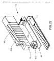
- FIG. 15is an exploded view of a copper-to-fiber optic active jack
- FIG. 16is a perspective view of a fiber optic active jack
- FIG. 17is a perspective view of a fiber optic active jack
- FIG. 18is a plan view of an active jack for wall plate mounting
- FIG. 19is a cross-sectional view along the line C—C of FIG. 18 ;
- FIG. 20is a front view of a wall plate with an active jack installed
- FIG. 21is a cross-sectional view along the line D—D of FIG. 20 ;
- FIG. 22is a perspective view of an active jack for wall plate mounting
- FIG. 23is a perspective view of an active jack for wall plate mounting
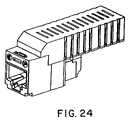
- FIG. 24is a perspective view of a fiber optic active jack for wall plate mounting
- FIG. 25is a perspective view of a fiber optic active jack for wall plate mounting
- FIG. 26is a plan view of an alternate construction of an active jack for wall plate mounting
- FIG. 27is a perspective view of an alternate construction of an active jack for wall plate mounting
- FIG. 28is an exploded view of an alternate construction of an active jack for wall plate mounting
- FIG. 29is a perspective view of a contact carrier with assembled contacts
- FIG. 30is a side cutaway view showing a contact
- FIG. 31is a side cutaway view showing another contact
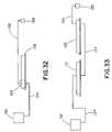
- FIG. 32is a plan view of an inter-connect installation
- FIG. 33is a plan view of a cross-connect installation
- FIG. 34is a schematic drawing showing a fiber optic and twisted pair cable deployment of a communication system
- FIG. 35is a schematic drawing showing cable deployment
- FIG. 36is a schematic drawing showing fiber optic cable deployment
- FIG. 37is a schematic drawing of a power-and twisted pair patch cord
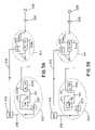
- FIG. 38is a plan view of a power-and-data system in an interconnect-to-interconnect patch panel deployment
- FIG. 39is a plan view of a power-and-data system in an interconnect-to-interconnect patch panel deployment using fiber optic cable;
- FIG. 40is a plan view of a power-and-data system in a cross-connect-to-interconnect patch panel deployment
- FIG. 41is a plan view of a power-and-data system in a cross-connect-to-interconnect patch panel deployment using fiber optic cable;
- FIG. 42is a plan view of a power-and-data system in an interconnect patch panel deployment without a consolidation point
- FIG. 43is a plan view of a power-and-data system in a cross-connect patch panel deployment without a consolidation point
- FIG. 44is a plan view of a power-and-data system in an interconnect patch panel deployment without a consolidation point and using fiber-optic cable;
- FIG. 45is a plan view of a power-and-data system in a cross-connect patch panel deployment without a consolidation point and using fiber-optic cable;
- FIG. 46is a plan view of a power-and-data system having a two-way Ethernet server.
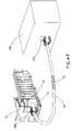
- FIG. 47is a schematic drawing showing a communication system in which power is provided to a network powered device via a jack.
- Active jacksmay be considered Ethernet network repeaters that contain media access control (MAC) ID chips and that respond to query signals from a network source with the ID of the jack. They also provide functions required by various standards for PDs. They optionally provide additional functions as described in the above-referenced U.S. patent application Ser. No. 10/439,716.
- MACmedia access control
- active jacksWhen active jacks are installed, their physical locations are recorded in a network system. When a response from a network information query is received on a particular source of a network path (i.e., a particular port of a switch), the system software combines this information with the above-described physical location information and documents network physical structure.
- a standard active jack(“A-Jack”) is the jack to which a destination device (e.g., a voice-over-Internet-protocol (VOIP) telephone) is connected.
- a patch panel active jack(“P-Jack”) is a jack on a patch panel.
- a P-Jack patch panelincorporates a “mother” printed circuit board to which each P-Jack module is electrically connected. Local power is optionally supplied through the motherboard.
- common electronic elements of P-Jacksare located on the motherboard.
- A-Jacks and P-Jackswhich may be termed twisted-pair active jacks, have a twisted-pair input and output.
- Another type of A-Jacks and P-Jacksincludes an integral media converter and connects between twisted-pair and fiber optic plugs; these may be termed fiber optic active jacks.
- active jackssupport different Ethernet systems.
- Onesupports 10 Base T and 100 Base TX.
- Active jacksrequire power which can be supplied locally or, for twisted-pair active jacks, may be supplied by signal cables. According to one embodiment, power for fiber optic active jacks is supplied locally. If power is supplied locally to an A-Jack by a local power supply (called a brick), a preferred embodiment uses a 5-pair combination signal and power patch cord connected between the A-Jack and the workstation location.
- a local power supplycalled a brick
- the active jack systemfacilitates the real-time documentation of a complete network and preferred embodiments facilitate installation and revision.
- a prior art installation methodincludes conforming to a physical design in which the location of each element of a network is specified.
- a system to guide the installation and revisionis provided which facilitates this installation method.
- An alternative and preferred method which can be used with the active jack systemis to install each element of a group in random locations and subsequently to document the installation. For example, all connections from a switch to a patch panel can be randomly connected. All patch cords for a group can be randomly connected. All horizontal cables of a group can be randomly connected on the downstream patch panel.
- A-Jacksare employed in a network with or without P-Jacks. This is utilized, for example, in a “911 location” system. The system knows what the fixed physical location of each A-Jack is. The system also knows which network path each A Jack was connected to the last time a network information query was made and therefore deduces the physical location of a 911 call received on the same network path as the A-Jack. Queries can be made frequently, when a 911 call is received, or both.
- power for twisted-pair active jackscan be supplied by the signal cables. In some cases, such power is supplied from the switch. When such power is not supplied from the switch in this embodiment, it can be supplied locally, by a so-called brick. However, it is preferable to supply it by the signal cables. Such power can be supplied for 10 Base T/100 Base TX Ethernet networks by a patch panel with passive jacks which supplies power downstream. A preferred embodiment of such a patch panel incorporates a motherboard to which each passive jack module is electrically connected.
- Such power for a 1 GbE Ethernet networkwhich utilizes four twisted pairs for signals, cannot be supplied by such a patch panel with passive jacks because it is a mid-span device and the specifications do not allow power to be added to signal-carrying pairs by a mid-span device. It should be noted that active patch panels are permitted under the specification to supply downstream power because they are repeaters, which regenerate the signals.
- a 911-location systemmay be employed in which a VOIP phone that is a PD device (that is, a device which requires power) is connected to an A-Jack.
- the VOIP phonegets its power from the signal cables or from a local power supply (a so-called brick).
- a VOIP phonegets its power from the signal cables or from a local power supply (a so-called brick).
- the power to itgoes from off to on.
- the power to italso goes from off to on if any part of the network path it is on, e.g., a patch cord, has been changed.
- the VOIP phonesends an ARP (address resolution protocol) message containing its unique I.D. number on the network.
- ARPaddress resolution protocol
- the A Jacksends an ARP message containing its unique ID number on the network.
- the network systemknows what network path these ARP messages are received on.
- the network systemalso knows the physical location of each A-Jack. This system therefore always knows the physical location of each VOIP phone.
- Network Information queries to entire networksare typically made at intervals, e.g., several times a day.
- a preferred 911-location systemwill be programmed to send a network information query each time a VOIP phone sends an ARP message which wasn't in response to a network information query. This preferred system therefore always knows which VOIP phone is connected to which A-Jack and always knows the physical location of each VOIP phone.
- P-Jack patch panelsare provided in some embodiments of the present invention.
- P-Jack patch panelsare modular.
- a patch panel structureincorporates a mother PCB and P-Jack modules snap into and out of the patch panel.
- Each patch panelsupports any combination of 10 Base T, 100 Base TX and 1 GbE Ethernet systems.
- a variety of P-Jack modulessnap in or out of each patch panel. These include UTP and STP twisted-pair and fiber optic active P-Jacks. The same variety of A-Jacks are available. This embodiment facilitates the upgrading of horizontal cabling of a network by simply upgrading the active jacks and the horizontal cables.
- Patch panels according to the present inventionmay also be used to hold passive “non-active” twisted pair communication jacks as shown by the exploded view of patch panel 23 of FIG. 1 .
- the non-active jacks 24 and a motherboard 26 holding contact carriers 28are assembled together using inserts 30 .
- the motherboard 26 and the contact carriers 28are configured to provide only power to the jacks 24 , rather than both power and data as in “active” communication jack embodiment.
- Patch panels according to this inventionmay be used to provide power to PDs in deployments that utilize unused signal pairs to transmit power.
- the motherboardprovides electrical power to a network powered device via the modular jack over a pair of network cable conductors.
- Covers 32are provided for protecting the motherboard 26 and the contact carriers 28 , and a frame 34 is provided to hold and protect the entire patch panel assembly.
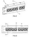
- FIG. 2shows a perspective view of a segment of the patch panel 23 of FIG. 2 , with the frame 34 overlapping and covering the inserts 30 .
- a front view of the patch panel 23is shown in FIG. 3 , showing the jacks 24 housed within the frame 34 .
- FIG. 4is a cross-sectional view along the line A—A of FIG. 3 showing a jack 24 within a frame 34 .
- An insert 30holds a printed circuit board (PCB) of the motherboard 26 , upon which a contact carrier 28 is mounted.
- Data contacts 38 of the jack 24extend into an outlet 40 of the jack 24 .
- Jack power contacts 42are seated beneath the outlet 40 , and reside within a power contact channel 44 .
- Poweris provided to the jack power contacts 42 via contact carrier power contacts 46 .
- the contact carrier power contacts 46are biased against the jack power contacts 42 due to spring tension within the contact carrier power contacts 46 .
- there are two jack power contacts 42 and two contact carrier power contacts 46there are two jack power contacts 42 and two contact carrier power contacts 46 , and the motherboard 26 is adapted to supply power to the jack power contacts 42 of the jack 24 without the need for additional contacts between the jack 24 and the motherboard 26 .
- the jack 24may be assembled from three pieces: an outer jack housing 48 , a contact module 50 , and an insulation displacement connector (IDC)/punch-down connector 52 .
- the contact module 50contains a jack PCB 54 that is connected to the data contacts 38 and IDCs 56 .
- the jack power contacts 42are also connected to the jack PCB 54 .
- the outer jack housing 48 and the contact module 50are joined together as shown in FIG. 5 b .
- the jack power contacts 42are inserted into the power contact channels 44 , and the data contacts 38 are positioned within the outlet 40 .
- IDC slots 58 of the IDC/punch-down connector 52are aligned with the IDCs 56 , and assembly tabs 60 of the IDC/punch down connector 52 are attached to the outer jack housing 48 to form an assembled jack 24 as shown in FIG. 5 c.
- the patch panel 10has a number of active P-jacks 12 adapted to communicate with a motherboard 14 having a number of contact carriers 16 .
- Patch panels according to the present inventionmay be used to provide power to devices in deployments such as power-over-Ethernet (PoE) deployments.
- PoEpower-over-Ethernet
- the motherboard in the patch panelprovides electrical power to a network powered device via one of the active P-jacks over a pair of network cable conductors (in other embodiments, the motherboard provides electrical power to a network powered device via one of the A-jack over a pair of network cable conductors).
- one contact carrieris provided for each of the active jacks 12 .
- each of the inserts 18is adapted to hold four active jacks 12 .
- a frame 22is provided for mounting and protecting the other components of the patch panel 10 .
- Active jacks used with the present inventionmay be active jacks of the type shown and described in co-pending U.S. patent application Ser. No. 10/439,716, entitled “Systems and Methods for Managing a Network,” filed on May 16, 2003, and incorporated herein by reference in its entirety.
- FIG. 7a patch panel assembly 10 populated with active jacks 12 is shown.
- the active jacks 12 of the embodiment shown in FIG. 7comprise a connector port 68 for holding a communications plug and space on a PCB for holding common electronic components of the active jacks 12 .
- the connector port 68is an RJ-45 port.
- Indicator lights 72are provided on the front and rear of the active jacks 12 for providing cable revision and installation signals to a network revisor or installer.
- from two to ten active jack motherboard contacts 74are provided.
- FIG. 8is a front view of the patch panel 10 of FIG. 7 , showing the active jacks 12 seated within the frame 22 .
- management-and-power assignments for an eight-pin embodimentis:
- FIG. 9a cross-sectional view of the line B—B of FIG. 8 is shown.
- the frame 22holds the insert 18 , which in turn holds the active jack 12 .
- the active jack 12includes an outlet 76 for accepting a communications plug.
- a communications cable 78is connected to the active jack 12 by means of a termination cap 258 .
- An active jack PCB 80contains electronics necessary for individual active jacks, while electronics common to all active jacks within a patch panel are provided on a motherboard PCB 82 .
- Data contacts 84extend into the outlet 76 .
- the electronics area 70may hold common electronic components necessary for each active jack 12 .
- the motherboard 14is shown in FIG. 9 , with the motherboard PCB 82 holding a contact carrier 16 .
- Motherboard contacts 74are biased against active jack PCB contacts 86 via spring tension within the motherboard contacts 74 .
- the active jack PCB contacts 86extend downwardly from the active jack PCB and route electronic signals and power to and from the electronic components 71 resident on the active jack PCB 80 .
- the motherboard 14may be connected to an individual power supply for each patch panel 10 and route power to each jack on the patch panel that requires power.
- the embodiments of FIG. 9may be used with fiber optic active jacks as shown in FIGS. 15–17 . As shown in FIG.
- the motherboard 14when a communications cable 78 is connected between the active jack 12 of the patch panel 10 and the jack 195 of a network powered device 196 , the motherboard 14 provides electrical power to the network powered device 196 via the jack 12 over a pair of network cable conductors 79 of the communications cable 78 .
- FIG. 10A rear view of patch panel 10 is shown in FIG. 10 with communications cables 78 connected to the active jacks 12 .
- active jacks 12may be installed into the inserts 18 without cables attached, and the cables may be attached following installation.
- Indicator lights 72can also be seen at the rear of active jack 12 in FIG. 10 , providing cable revision and installation signals to a network revisor or installer.
- FIGS. 11 and 12show an assembled active jack 12 .
- An indicator light 72is present at both ends.
- Active jack PCB contacts 86are open to air.
- Notches 240 and slots 242 in the active jack 12provide a means to exchange warmer air inside the jack 12 housing with cooler surrounding air.
- FIG. 12shows a latch feature 244 to hold the active jack 12 in the insert 18 .
- FIGS. 13 and 14show an insert 18 for mounting active jacks 12 .
- a latch feature 244 on the active jack 12mates with receptacle feature 246 on insert 18 .
- Front stops 248align with recesses 256 on the front face of active jack 12 .
- Cooling slots 250 in the insert 18aid in the exchange of warmed air.
- Latch features 252hold insert the 18 in the frame 22 .
- a support arm 254mounts the motherboard assembly 14 .
- a fiber optic active jackmay be provided for use with patch panels according to the present invention.
- an SFF duplex fiber optic plug receptacle 120is provided with media converter and/or transceiver electronics mounted in an electronics mounting area 122 on a fiber optic jack PCB 124 .
- the electronics mounting area 122has been shown on the top of the fiber optic jack PCB 124 , it is to be understood that electronic components may alternatively or additionally be mounted on the underside of the PCB 124 .
- an electronics cover 126is shown covering the electronics components.
- FIGS. 18 and 19show an active A-jack 276 for use in wall plates.
- FIG. 18shows cooling notches 240 and slots 242 .
- Mounting features 260 and 274provide means to retain this active jack in a wall plate.
- FIG. 19is a cross-sectional view of an active jack 276 along the line C—C of FIG. 18 .
- Housings 268 and 278enclose two secondary PCB's 270 and 272 .
- An outlet 76is provided with contacts 84 to mate to a telecommunications plug, (e.g., an RJ-45 plug).
- Contacts 84are inserted into a first PCB 262 . This PCB makes electrical contact to the secondary PCB 270 through a connector 266 .
- Secondary PCB's 270 and 272are connected electrically to each other as well.
- a communications cable 78is connected to the active jack 276 through a termination cap 258 , an IDC connection 264 , and the primary PCB 262 .
- Wall plate jacksrequire the indicator light 72 on the front face only.
- FIGS. 20 and 21show the typical use of the wall plate active jack 276 .
- FIG. 20is a typical wall plate 280 with a four positions. Latching features 262 and 264 and front stop 248 retain the active jack 276 in the wall plate 280 .
- FIGS. 22 and 23show an assembled twisted pair active jack 276 .
- FIGS. 24 and 25show an assembled fiber optic active jack.
- FIGS. 26–28show an alternative embodiment of the active jack construction.
- PCB housings 286 and 288are split at a middle point of their assembled height.
- Offsetting features 292 and 290(shown in FIG. 28 ) provide alignment means. This construction allows for full-length and full depth cooling slots 242 in the vertical sides of active jacks, increasing the cooling capabilities of the slot array.
- FIG. 29A contact carrier 16 in which the contacts 74 are seated within contact alignment slots 110 is shown in FIG. 29 .
- the contacts 74have been pushed in the direction shown by arrow “I” in FIG. 30 (in the direction of a housing ridge 112 within the contact housing 94 ) until contact latching ends 114 latch beneath a housing latch 116 .
- spring tension within the contacts 74provides the contacts 74 with freedom of movement in the direction of arrow “J” shown in FIG. 31 and the housing latch 116 prevents the contacts 74 from springing upwardly out of the contact housing 94 .
- fiber optic jacks with patch panelsallows for extended runs of cabling with decreased signal degradation and decreased crosstalk.
- a patch panel 128 having fiber optic active jacks 130 installed thereinis shown in an inter-connect installation.
- An active network devicesuch as a switch 132 is connected to the patch panel 128 via a patch cord 134 .
- the fiber optic active jack 130is adapted to translate signals between the twisted pair cable 134 and a fiber optic cable 136 .
- the fiber optic cable 136is connected at its other end to a fiber optic active jack 138 , such as a wall jack, which may, in turn, be connected to user-end network devices.
- Fiber optic compatible active jacksmay also be employed in cross-connect systems as shown in FIG. 33 .
- an active network elementsuch as a switch 132 is connected via a patch cord 134 to a patch panel such as an active-jack patch panel 10 .
- the active-jack patch panel 10is, in turn, connected to a patch panel 128 populated with fiber optic active jacks via a patch cord 134 .
- Each fiber optic active jackis connected via a fiber optic cable 136 to a fiber optic active jack 138 .
- fiber optic cables 136requires the provision of local power to the fiber optic active jack 138 .
- a PoE Ethernet switch 140is connected to a modular patch panel 142 via a plurality of patch cords 144 .
- the modular patch panel 142is connected to the fiber optic active jack 138 via a simplex or duplex fiber optic cable 136 (which may be a single-mode or a multi-mode fiber optic cable).
- the modular patch panel 142is connected to twisted-pair active jacks 146 via twisted-pair cables.
- the fiber optic active jack 138can receive power from a PoE brick 148 .
- the PoE brick 148routes power to a user device 149 via a user-side patch cord 150 and routes power to active jacks 138 via a work area patch cord 152 .
- the PoE brick 148receives power such as AC power from an AC power cord 154 .
- twisted-pair active jacks 146may be provided with power from the PoE Ethernet switch 140 , from a mid-span device, or from a powered patch panel.
- Fiber optic active jacksare addressed as PDs in a PoE deployment.
- the use of fiber optic cables 136is beneficial when long connection lengths (for example, greater than 100 m) are necessary.
- Communication speedssuch as 10, 100, or 1000 Mbps are possible, and the same or similar fiber optic active jacks may be located at the patch panel 142 and at destination outlet 213 .
- horizontal cabling runscan be changed from twisted-pair runs to fiber optic runs simply by changing two modules and the cable.
- FIGS. 35 and 36show deployment scenarios for fiber optic communications enabled by the present invention.
- a communication networkcan be divided into zones appropriate for different types of cabling.
- a twisted-pair (e.g., copper) cabling zone 156is shown with a range of approximately 100 m of cabling and a fiber optic run 158 is shown for long-range applications.
- the fiber optic run of FIG. 35is 2 km long.
- FIG. 36shows the use of fiber optic cables with consolidation points and shared media switches.
- a patch panel with fiber optic active jacks 160is connected via a multiple-fiber optic cable 162 to a consolidation point 164 .
- the multiple-fiber optic cable 162is translated to individual fiber optic cables 170 .
- Single fibers 166may be routed between the patch panel with fiber optic active jacks 160 and a shared media switch 168 , with the shared media switch 168 being connected to active jacks 276 .
- a single fiber optic cable 172may be used to directly connect the patch panel with fiber optic active jacks 160 to active jacks 276 .
- the user-end connections 170may be any type of communications cable, as required in the particular deployment.
- FIG. 37illustrates a system for providing power to a device, such as a VOIP phone, using a local power supply.
- a jack 194is adapted to handle the communications and power-supply needs of a user device 196 , such as a VOIP phone.
- a power-and-data patch cord 198is provided with a ten-conductor portion 200 that terminates at a plug 202 shown inserted into the jack 194 .
- An eight-conductor portion 204 of the cable 198terminates at a plug 206 for insertion into the user device 196 .
- a two-conductor portion 208 of the cable 198terminates at a plug 210 that is inserted into a local power supply 212 .
- poweris routed from the power supply 212 to the jack 202 , which re-routes the power necessary for the user device 196 to the user device 196 via the eight-conductor portion 204 of the cable 198 .
- Telecommunications Industry Association/Electronic Industries Association (“TIA/EIA”) Specification TSB75includes Consolidation Point (i.e., Zone Enclosure) specifications. It allows one interconnection point within the horizontal cabling from a telecommunications closet to the outlet. The cables on both sides of the consolidation point are part of the same horizontal cable run.
- TIA/EIATelecommunications Industry Association/Electronic Industries Association
- TSB75includes Consolidation Point (i.e., Zone Enclosure) specifications. It allows one interconnection point within the horizontal cabling from a telecommunications closet to the outlet. The cables on both sides of the consolidation point are part of the same horizontal cable run.
- FIGS. 38–46describe various network infrastructure configurations that utilize active jacks to provide a network documentation and 911 call location system.
- the 911 call location systemincludes a table of VOIP phone MAC I.D. numbers vs. the last known physical location of that phone. A phone which is disconnected from the network will remain in the table, however, a call cannot be made from a disconnected phone. If however, the phone is reconnected to the network, the table will be immediately updated with the current location of the phone. This system is therefore online, accurate and provides an immediate answer.
- every powered devicesends an ARP response immediately following interruption and restoration of its Ethernet signal and/or its power supply.
- a documentation systemmay be employed with no manual intervention, provided all network infrastructure revisions are confined to changes in patch cord routing and/or changes in which outlets destination devices are connected to. If this procedure is followed, this documentation system will provide online up-to-date documentation, including the horizontal cable locations and identification information which were manually documented when installed and/or revised, and all patch cord routings.
- the network configurations as illustrated in FIGS. 38–46do not have a switch in the network path between the P-Jack and the VOIP phone.
- a destination devicee.g., a VOIP phone
- the power and/or signal interruptionwill trigger an ARP response from it, and the network path it is on will always be known. Since the physical locations of all P-Jacks and all outlets are known and all horizontal cables—including those that connect each outlet to a P-Jack—are fixed, complete documentation is known by state-of-the-art software systems.
- each outlet and the MAC I.D. of the P-Jack to which it is connectedcan be manually entered into state-of-the-art software by following existing procedures.
- the validitycan be checked by plugging a PD (powered device) with a known MAC I.D. into the outlet and reading the documentation report.
- a portable computercould be plugged into each outlet, one at a time.
- the work orderwhich includes the physical locations of the outlets, could be brought up on a screen of the PC and the physical location information could be entered into the system using, for example, a computer mouse.
- softwareis used to add this fixed location information into the documentation system.
- an LED which is visible on the front and back of each P-Jackcan assist the revision process.
- softwarecontrols each LED, and Ethernet signals received by each P-Jack cause the P-Jacks to turn their LEDs on and off. Therefore, the LED signals in this embodiment can be provided only when the P-Jack is connected to the network.
- a different color LED on each P-Jackmay be used to provide power-over-Ethernet (PoE) information.
- FIG. 38a system is shown for providing power and data connections to P-Jack patch panels 214 a and 214 b .
- An uninterruptible power supply (UPS) 216supplies power (preferably, AC power) along UPS power cables 218 to local UPS power supplies 220 .
- the local UPS power supplies 220are adapted to provide 48 V AC power.
- the local UPS power supplies 220provide power to networking equipment via local UPS power supply cables 221 .
- two network equipment groupsare shown: a communication closet 222 and a consolidation point 164 .
- the communication closet 222could be located in alternative locations, such as at a network operations center or other physical location where network equipment is located.
- the communication closet 222 and the consolidation point 164are connected in the embodiment of FIG. 45 by a run of twisted-pair horizontal cable 224 a.
- the local UPS power supply 220supplies power to a switch 132 and to the P-Jack patch panel 214 a .
- the switch 132 and the P-Jack patch panel 214 aare connected by a patch cord 134 for carrying data.
- the local UPS power supply 220supplies power to the P-Jack patch panel 214 b via a local UPS power supply cable 221 .
- the P-Jack patch panel 214 bis connected via a twisted-pair horizontal cable 224 b to a workstation outlet 226 , which in turn is connected to a destination device 228 , such as a VOIP phone.
- the workstation outlet 226is a passive jack outlet. Power is supplied to the destination device 228 using PoE.
- FIG. 39a system is shown for providing power and data connections to two interconnect locations connected by a fiber-optic cable.
- the system of FIG. 39is similar to the system of FIG. 38 , but a fiber-optic cable run 158 serves as the horizontal connection between the two P-Jack patch panels 214 c and 214 d .
- the P-Jack patch panels 214 c and 214 dare adapted for fiber-optic communication, as described above.
- FIG. 40shows a system for providing power and data connection between a cross-connect location and an interconnect location connected by a twisted-pair horizontal cable 224 a .
- the communication closet 222contains two patch panels in a cross-connect configuration.
- a passive-jack patch panel 230is cross-connected with a P-Jack patch panel 214 a .
- the deployment of this embodimentis similar to the deployment of FIG. 38 , with the inclusion of a cross-connect configuration at the communication closet 222 .
- FIG. 41shows a system for providing power and data connections between a cross-connect location and an interconnect location connected by a fiber-optic cable run 158 .
- the system of FIG. 41is similar to the system of FIG. 40 , with the inclusion of P-Jack patch panels 214 c and 214 d adapted for fiber-optic communication over the fiber-optic cable run 158 .
- FIG. 42a power-and-data system is shown in which an interconnect patch panel location is deployed without a consolidation point.
- the communication closet 222is an interconnect patch panel location
- the P-Jack patch panel 214 ais directly connected to a workstation outlet 226 via a twisted-pair horizontal cable 224 .
- a UPS 216 and a local UPS power supply 220supply power to network components at the communication closet 222 .
- FIG. 43A similar deployment is shown in FIG. 43 , in which a cross-connect patch panel location is deployed without a consolidation point.
- a passive jack patch panel 230 and a P-Jack patch panel 214 aare cross-connected at the communication closet 222 , and a twisted pair communication cable 224 connects the P-Jack patch panel 214 a to the workstation outlet 226 .
- FIG. 44a deployment is shown in which an interconnect patch panel is connected to an active jack workstation outlet 232 via a horizontal fiber-optic cable run 158 , with no consolidation point.
- Poweris supplied to the destination device 228 and to the active jack workstation outlet 232 by a local power supply 212 , and the UPS 216 supplies power via a local UPS power supply 220 to the P-Jack patch panel 214 a and the switch 132 .
- systems and methods according to the present inventionmay be used in a power-and-data deployment in which patch panels in a cross-connect configuration are connected to an active jack workstation outlet 232 via a fiber-optic cable 158 .
- a local power supply 212supplies power to the destination device 228 and the active jack workstation outlet 232 .
- the P-Jack patch panels 214 care adapted for fiber-optic communication.
- FIG. 46shows the substitution of a two-way Ethernet server 234 and integral peripheral device 236 for an outlet and destination device. This provides all the functions of an A-Jack, PoE, and an Ethernet interface to the peripheral device.
- the local UPS power supply 220 and the P-Jack patch panel 214may be provided at a consolidation point 164 .
- the network configurations illustrated in FIGS. 38–46include only one VOIP phone on the same network path as the P-Jack. If an additional VOIP phone is on the same network path, both phones must be in the same proximate location.
Landscapes
- Small-Scale Networks (AREA)
- Structure Of Telephone Exchanges (AREA)
Abstract
Description
This application claims the benefit of U.S. Provisional Patent Application Ser. No. 60/524,654, filed Nov. 24, 2003 and entitled “Communications Patch Panel Systems and Methods,” U.S. Provisional Patent Application Ser. No. 60/529,925, filed Dec. 16, 2003 and entitled “Communications Patch Panel Systems and Methods,” and U.S. Provisional Patent Application Ser. No. 60/537,126, filed Jan. 16, 2004 and entitled “Communications Patch Panel Systems and Methods,”.
This application incorporates by reference in its entirety U.S. patent application Ser. No. 10/439,716, entitled “Systems and Methods for Managing a Network,” filed on May 16, 2003; U.S. Provisional Application Ser. No. 60/492,822, entitled “Network Managed Device Installation and Provisioning Technique,” filed on Aug. 6, 2003; U. S. Provisional Application, entitled “System to Guide and Monitor the Installation and Revision of Network Cabling of an Active Jack Network System,” filed Oct. 23, 2003; and U.S. Provisional Application Ser. No. 60/529,925, entitled “Communications Patch Panel Systems and Methods,” filed Dec. 16, 2003, as well as all materials incorporated therein by reference.
Prior art systems do not provide real time documentation of every power device, PD, connected to a network including PDs which can be moved from one physical location to another, i.e., a VOIP telephone.
Installation and maintenance of communications patch panels are complex processes that generally require the work of highly skilled installers and network managers. Further, connecting communications cables to communications patch panels generally requires detailed instructions and great care on the part of an installer. It is desirable to provide a communications patch panel that simplifies the process of installing and maintaining a patch panel and further simplifies the routing of communications cables to and from patch panels.
The present invention is directed to systems and methods that facilitate the installation of communications cabling and communications patch panels. Systems and methods of the present invention further facilitate the maintenance and revision of installed cable and the maintenance of communications patch panels.
This invention provides a dynamic real time system that documents which power devices, hereinafter called PDs, are connected on each path of a network. This is invaluable for critical functions including maintenance of service, planning of revisions, execution of revisions, diagnosis of problems, and determination of the physical location of a VOIP phone from which an emergency call was made.
Prior art systems provide such information, however, they do not provide reliable documentation in real time.
According to one embodiment of the present invention, an active jack, which is a PD, is installed as the network connection at a workstation in combination with a patch panel which contains an active jack, which is a PD, said active jacks being part of the same network path.
According to another embodiment of the present invention, an active jack which is the only active jack which is part of a network path is installed as the network connection at a workstation.
According to another embodiment of the present invention, systems and methods are provided by which a communications patch panel is provided with a number of active jacks for enhancing communications network installation, revision, management and documentation.
According to another embodiment of the present invention, a communications patch panel is provided with a motherboard that contains some common components and/or power connections for active jacks.
According to another embodiment of the present invention, a patch panel is provided in which modular jacks may be inserted or removed, with at least some necessary electronics for certain modular jacks being provided within the patch panel.
According to another embodiment of the present invention, several types of modular jacks are provided, including twisted-pair active jacks, and fiber optic active jacks.
Patch panels according to the present invention may be equipped to provide power to a jack in the patch panel and/or to a PD which is connected to said jack by twisted pair cables.
While the invention is susceptible to various modifications and alternative forms, specific embodiments are shown by way of example in the drawings and are described in detail herein. However, it should be understood that the invention is not intended to be limited to the particular forms disclosed. Rather, the invention is to cover all modifications, equivalents, and alternatives falling within the spirit and scope of the invention as defined by the appended claims.
Active jacks according to the present invention may be considered Ethernet network repeaters that contain media access control (MAC) ID chips and that respond to query signals from a network source with the ID of the jack. They also provide functions required by various standards for PDs. They optionally provide additional functions as described in the above-referenced U.S. patent application Ser. No. 10/439,716. When active jacks are installed, their physical locations are recorded in a network system. When a response from a network information query is received on a particular source of a network path (i.e., a particular port of a switch), the system software combines this information with the above-described physical location information and documents network physical structure.
Active jacks according to the present invention may be provided in several varieties. A standard active jack (“A-Jack”) is the jack to which a destination device (e.g., a voice-over-Internet-protocol (VOIP) telephone) is connected. A patch panel active jack (“P-Jack”) is a jack on a patch panel. In a preferred embodiment, a P-Jack patch panel incorporates a “mother” printed circuit board to which each P-Jack module is electrically connected. Local power is optionally supplied through the motherboard. In addition, common electronic elements of P-Jacks are located on the motherboard.
One type of A-Jacks and P-Jacks, which may be termed twisted-pair active jacks, have a twisted-pair input and output. Another type of A-Jacks and P-Jacks includes an integral media converter and connects between twisted-pair and fiber optic plugs; these may be termed fiber optic active jacks.
In preferred embodiments, active jacks support different Ethernet systems. One supports 10 Base T and 100 Base TX. Another supports 1 GbE (1000 Base T).
Active jacks require power which can be supplied locally or, for twisted-pair active jacks, may be supplied by signal cables. According to one embodiment, power for fiber optic active jacks is supplied locally. If power is supplied locally to an A-Jack by a local power supply (called a brick), a preferred embodiment uses a 5-pair combination signal and power patch cord connected between the A-Jack and the workstation location.
The active jack system facilitates the real-time documentation of a complete network and preferred embodiments facilitate installation and revision. A prior art installation method includes conforming to a physical design in which the location of each element of a network is specified. A system to guide the installation and revision is provided which facilitates this installation method. An alternative and preferred method which can be used with the active jack system is to install each element of a group in random locations and subsequently to document the installation. For example, all connections from a switch to a patch panel can be randomly connected. All patch cords for a group can be randomly connected. All horizontal cables of a group can be randomly connected on the downstream patch panel.
In another embodiment, A-Jacks are employed in a network with or without P-Jacks. This is utilized, for example, in a “911 location” system. The system knows what the fixed physical location of each A-Jack is. The system also knows which network path each A Jack was connected to the last time a network information query was made and therefore deduces the physical location of a 911 call received on the same network path as the A-Jack. Queries can be made frequently, when a 911 call is received, or both.
As previously noted, power for twisted-pair active jacks can be supplied by the signal cables. In some cases, such power is supplied from the switch. When such power is not supplied from the switch in this embodiment, it can be supplied locally, by a so-called brick. However, it is preferable to supply it by the signal cables. Such power can be supplied for 10 Base T/100 Base TX Ethernet networks by a patch panel with passive jacks which supplies power downstream. A preferred embodiment of such a patch panel incorporates a motherboard to which each passive jack module is electrically connected.
Such power for a 1 GbE Ethernet network, which utilizes four twisted pairs for signals, cannot be supplied by such a patch panel with passive jacks because it is a mid-span device and the specifications do not allow power to be added to signal-carrying pairs by a mid-span device. It should be noted that active patch panels are permitted under the specification to supply downstream power because they are repeaters, which regenerate the signals.
A 911-location system may be employed in which a VOIP phone that is a PD device (that is, a device which requires power) is connected to an A-Jack. The VOIP phone gets its power from the signal cables or from a local power supply (a so-called brick). In either case, when a VOIP phone is first installed or is installed in a new location, the power to it goes from off to on. The power to it also goes from off to on if any part of the network path it is on, e.g., a patch cord, has been changed. When the power to it goes from off to on, the VOIP phone sends an ARP (address resolution protocol) message containing its unique I.D. number on the network. In the same way, when the power to an A Jack goes from off to on, the A Jack sends an ARP message containing its unique ID number on the network. The network system knows what network path these ARP messages are received on. The network system also knows the physical location of each A-Jack. This system therefore always knows the physical location of each VOIP phone.
Network Information queries to entire networks are typically made at intervals, e.g., several times a day. However, a preferred 911-location system will be programmed to send a network information query each time a VOIP phone sends an ARP message which wasn't in response to a network information query. This preferred system therefore always knows which VOIP phone is connected to which A-Jack and always knows the physical location of each VOIP phone.
P-Jack patch panels are provided in some embodiments of the present invention. In a preferred embodiment, P-Jack patch panels are modular. A patch panel structure incorporates a mother PCB and P-Jack modules snap into and out of the patch panel. Each patch panel supports any combination of 10 Base T, 100 Base TX and 1 GbE Ethernet systems. A variety of P-Jack modules snap in or out of each patch panel. These include UTP and STP twisted-pair and fiber optic active P-Jacks. The same variety of A-Jacks are available. This embodiment facilitates the upgrading of horizontal cabling of a network by simply upgrading the active jacks and the horizontal cables.
Patch panels according to the present invention may also be used to hold passive “non-active” twisted pair communication jacks as shown by the exploded view ofpatch panel 23 ofFIG. 1 . Thenon-active jacks 24 and amotherboard 26 holdingcontact carriers 28 are assembled together using inserts30. In the “non-active” communication jack embodiment shown inFIG. 1 , themotherboard 26 and thecontact carriers 28 are configured to provide only power to thejacks 24, rather than both power and data as in “active” communication jack embodiment. Patch panels according to this invention may be used to provide power to PDs in deployments that utilize unused signal pairs to transmit power. In one embodiment, the motherboard provides electrical power to a network powered device via the modular jack over a pair of network cable conductors.Covers 32 are provided for protecting themotherboard 26 and thecontact carriers 28, and aframe 34 is provided to hold and protect the entire patch panel assembly.
Turning now toFIGS. 5 a,5b, and5c, the assembly of a punch-downtype jack 24 according to one embodiment of the present invention is shown in a step-by-step process. Thejack 24 may be assembled from three pieces: anouter jack housing 48, acontact module 50, and an insulation displacement connector (IDC)/punch-down connector 52. Thecontact module 50 contains ajack PCB 54 that is connected to thedata contacts 38 andIDCs 56. Thejack power contacts 42 are also connected to thejack PCB 54.
To assemble thejack 24, theouter jack housing 48 and thecontact module 50 are joined together as shown inFIG. 5 b. In this step, thejack power contacts 42 are inserted into thepower contact channels 44, and thedata contacts 38 are positioned within theoutlet 40. Next,IDC slots 58 of the IDC/punch-down connector 52 are aligned with theIDCs 56, andassembly tabs 60 of the IDC/punch downconnector 52 are attached to theouter jack housing 48 to form an assembledjack 24 as shown inFIG. 5 c.
Turning now toFIG. 6 , apatch panel 10 is shown in an exploded view. Thepatch panel 10 has a number of active P-jacks 12 adapted to communicate with amotherboard 14 having a number ofcontact carriers 16. Patch panels according to the present invention may be used to provide power to devices in deployments such as power-over-Ethernet (PoE) deployments. In one such deployment, the motherboard in the patch panel provides electrical power to a network powered device via one of the active P-jacks over a pair of network cable conductors (in other embodiments, the motherboard provides electrical power to a network powered device via one of the A-jack over a pair of network cable conductors). In the embodiment ofFIG. 6 , one contact carrier is provided for each of the active jacks12. The active jacks12 and themotherboard 14 are held in place using inserts18. In the embodiment shown inFIG. 6 , each of theinserts 18 is adapted to hold fouractive jacks 12. Aframe 22 is provided for mounting and protecting the other components of thepatch panel 10. Active jacks used with the present invention may be active jacks of the type shown and described in co-pending U.S. patent application Ser. No. 10/439,716, entitled “Systems and Methods for Managing a Network,” filed on May 16, 2003, and incorporated herein by reference in its entirety.
Turning now toFIG. 7 , apatch panel assembly 10 populated withactive jacks 12 is shown. The active jacks12 of the embodiment shown inFIG. 7 comprise aconnector port 68 for holding a communications plug and space on a PCB for holding common electronic components of the active jacks12. According to one embodiment, theconnector port 68 is an RJ-45 port. Indicator lights72 are provided on the front and rear of theactive jacks 12 for providing cable revision and installation signals to a network revisor or installer. According to some embodiments, from two to ten active jack motherboard contacts74 (as shown inFIG. 9 ) are provided.FIG. 8 is a front view of thepatch panel 10 ofFIG. 7 , showing theactive jacks 12 seated within theframe 22. One example of management-and-power assignments for an eight-pin embodiment is:
Pin1: 48 V Power
Pin2: −48 V Return
Pin3: Ground
Pin4: 3.3 V Power
Pin5: Read/Write
Pin6: Data
Pin7: Clock
Pin8: Reset.
According to other embodiments it is desirable to separate pins assigned for power to the outermost pins, with reassignment of the other pins as necessary.
Turning now toFIG. 9 , a cross-sectional view of the line B—B ofFIG. 8 is shown. Theframe 22 holds theinsert 18, which in turn holds theactive jack 12. Theactive jack 12 includes anoutlet 76 for accepting a communications plug. Acommunications cable 78 is connected to theactive jack 12 by means of atermination cap 258. Anactive jack PCB 80 contains electronics necessary for individual active jacks, while electronics common to all active jacks within a patch panel are provided on amotherboard PCB 82.Data contacts 84 extend into theoutlet 76.
Theelectronics area 70 may hold common electronic components necessary for eachactive jack 12. Themotherboard 14 is shown inFIG. 9 , with themotherboard PCB 82 holding acontact carrier 16.Motherboard contacts 74 are biased against activejack PCB contacts 86 via spring tension within themotherboard contacts 74. The activejack PCB contacts 86 extend downwardly from the active jack PCB and route electronic signals and power to and from theelectronic components 71 resident on theactive jack PCB 80. Themotherboard 14 may be connected to an individual power supply for eachpatch panel 10 and route power to each jack on the patch panel that requires power. The embodiments ofFIG. 9 may be used with fiber optic active jacks as shown inFIGS. 15–17 . As shown inFIG. 47 , when acommunications cable 78 is connected between theactive jack 12 of thepatch panel 10 and thejack 195 of a network powereddevice 196, themotherboard 14 provides electrical power to the network powereddevice 196 via thejack 12 over a pair ofnetwork cable conductors 79 of thecommunications cable 78.
A rear view ofpatch panel 10 is shown inFIG. 10 withcommunications cables 78 connected to the active jacks12. In an alternative embodiment,active jacks 12 may be installed into theinserts 18 without cables attached, and the cables may be attached following installation. Indicator lights72 can also be seen at the rear ofactive jack 12 inFIG. 10 , providing cable revision and installation signals to a network revisor or installer.
Systems and methods according to the present invention may be utilized in connection with a number of types of jacks and may facilitate communications processes in a variety of communications environments. For example, as shown inFIGS. 15–17 , a fiber optic active jack may be provided for use with patch panels according to the present invention. In this embodiment an SFF duplex fiberoptic plug receptacle 120 is provided with media converter and/or transceiver electronics mounted in anelectronics mounting area 122 on a fiberoptic jack PCB 124. While theelectronics mounting area 122 has been shown on the top of the fiberoptic jack PCB 124, it is to be understood that electronic components may alternatively or additionally be mounted on the underside of thePCB 124. In the embodiment shown inFIGS. 16 and 17 , anelectronics cover 126 is shown covering the electronics components.
Acommunications cable 78 is connected to theactive jack 276 through atermination cap 258, anIDC connection 264, and theprimary PCB 262. Wall plate jacks require theindicator light 72 on the front face only.
Acontact carrier 16 in which thecontacts 74 are seated withincontact alignment slots 110 is shown inFIG. 29 . To form this completedcontact carrier 16, thecontacts 74 have been pushed in the direction shown by arrow “I” inFIG. 30 (in the direction of ahousing ridge 112 within the contact housing94) until contact latching ends114 latch beneath ahousing latch 116. Following this step, spring tension within thecontacts 74 provides thecontacts 74 with freedom of movement in the direction of arrow “J” shown inFIG. 31 and thehousing latch 116 prevents thecontacts 74 from springing upwardly out of thecontact housing 94.
The use of fiber optic jacks with patch panels according to the present invention allows for extended runs of cabling with decreased signal degradation and decreased crosstalk. For example, as shown inFIG. 32 , apatch panel 128 having fiber opticactive jacks 130 installed therein is shown in an inter-connect installation. An active network device such as aswitch 132 is connected to thepatch panel 128 via apatch cord 134. The fiber opticactive jack 130 is adapted to translate signals between thetwisted pair cable 134 and afiber optic cable 136. In the embodiment shown inFIG. 32 , thefiber optic cable 136 is connected at its other end to a fiber opticactive jack 138, such as a wall jack, which may, in turn, be connected to user-end network devices.
Fiber optic compatible active jacks according to the present invention may also be employed in cross-connect systems as shown inFIG. 33 . In this embodiment, an active network element such as aswitch 132 is connected via apatch cord 134 to a patch panel such as an active-jack patch panel 10. The active-jack patch panel 10 is, in turn, connected to apatch panel 128 populated with fiber optic active jacks via apatch cord 134. Each fiber optic active jack is connected via afiber optic cable 136 to a fiber opticactive jack 138.
The use offiber optic cables 136 requires the provision of local power to the fiber opticactive jack 138. In the embodiment shown inFIG. 34 , aPoE Ethernet switch 140 is connected to amodular patch panel 142 via a plurality ofpatch cords 144. Themodular patch panel 142 is connected to the fiber opticactive jack 138 via a simplex or duplex fiber optic cable136 (which may be a single-mode or a multi-mode fiber optic cable). Themodular patch panel 142 is connected to twisted-pairactive jacks 146 via twisted-pair cables. The fiber opticactive jack 138 can receive power from aPoE brick 148. ThePoE brick 148 routes power to auser device 149 via a user-side patch cord 150 and routes power toactive jacks 138 via a workarea patch cord 152. ThePoE brick 148 receives power such as AC power from anAC power cord 154. In embodiments such as the embodiment ofFIG. 34 , twisted-pairactive jacks 146 may be provided with power from thePoE Ethernet switch 140, from a mid-span device, or from a powered patch panel. Fiber optic active jacks are addressed as PDs in a PoE deployment. The use offiber optic cables 136 is beneficial when long connection lengths (for example, greater than 100 m) are necessary. Communication speeds such as 10, 100, or 1000 Mbps are possible, and the same or similar fiber optic active jacks may be located at thepatch panel 142 and atdestination outlet 213. According to some embodiments, horizontal cabling runs can be changed from twisted-pair runs to fiber optic runs simply by changing two modules and the cable.
In some embodiments of the present invention, such as embodiments in which power is not provided to a jack by network-side connections, it is necessary to provide local power to devices.FIG. 37 illustrates a system for providing power to a device, such as a VOIP phone, using a local power supply. Ajack 194 is adapted to handle the communications and power-supply needs of auser device 196, such as a VOIP phone. A power-and-data patch cord 198 is provided with a ten-conductor portion 200 that terminates at aplug 202 shown inserted into thejack 194. An eight-conductor portion 204 of thecable 198 terminates at aplug 206 for insertion into theuser device 196. A two-conductor portion 208 of thecable 198 terminates at aplug 210 that is inserted into alocal power supply 212. In this embodiment, power is routed from thepower supply 212 to thejack 202, which re-routes the power necessary for theuser device 196 to theuser device 196 via the eight-conductor portion 204 of thecable 198.
Systems and methods according to the present invention may be adapted to a number of different types of deployments. For example, Telecommunications Industry Association/Electronic Industries Association (“TIA/EIA”) Specification TSB75 includes Consolidation Point (i.e., Zone Enclosure) specifications. It allows one interconnection point within the horizontal cabling from a telecommunications closet to the outlet. The cables on both sides of the consolidation point are part of the same horizontal cable run.
Specification TSB75 specifies, “Moves, adds, and changes of service not associated with open office rearrangements should be implemented at the horizontal cross-connect in the telecommunications closet.” Therefore, if an open office rearrangement is made and corresponding changes in the destination of horizontal cabling are made, the network documentation which was manually input when installed must be manually updated.FIGS. 38–46 describe various network infrastructure configurations that utilize active jacks to provide a network documentation and 911 call location system. The 911 call location system includes a table of VOIP phone MAC I.D. numbers vs. the last known physical location of that phone. A phone which is disconnected from the network will remain in the table, however, a call cannot be made from a disconnected phone. If however, the phone is reconnected to the network, the table will be immediately updated with the current location of the phone. This system is therefore online, accurate and provides an immediate answer.
According to some embodiments of systems shown inFIGS. 38–46 , every powered device (PD) sends an ARP response immediately following interruption and restoration of its Ethernet signal and/or its power supply. Such a documentation system may be employed with no manual intervention, provided all network infrastructure revisions are confined to changes in patch cord routing and/or changes in which outlets destination devices are connected to. If this procedure is followed, this documentation system will provide online up-to-date documentation, including the horizontal cable locations and identification information which were manually documented when installed and/or revised, and all patch cord routings. The network configurations as illustrated inFIGS. 38–46 do not have a switch in the network path between the P-Jack and the VOIP phone.
With this system, regardless of whether a switch provides power-over-Ethernet, if a patch cord is changed, the signal interruption will trigger an ARP response from the associated P-Jack, and the network path that the P-Jack is on will therefore always be known.
If a destination device (e.g., a VOIP phone) is moved to a new location, the power and/or signal interruption will trigger an ARP response from it, and the network path it is on will always be known. Since the physical locations of all P-Jacks and all outlets are known and all horizontal cables—including those that connect each outlet to a P-Jack—are fixed, complete documentation is known by state-of-the-art software systems.
The physical location of each outlet and the MAC I.D. of the P-Jack to which it is connected can be manually entered into state-of-the-art software by following existing procedures. The validity can be checked by plugging a PD (powered device) with a known MAC I.D. into the outlet and reading the documentation report.
As an alternative, when the installation of a network infrastructure is complete a portable computer (PC) could be plugged into each outlet, one at a time. The work order, which includes the physical locations of the outlets, could be brought up on a screen of the PC and the physical location information could be entered into the system using, for example, a computer mouse. According to one embodiment, software is used to add this fixed location information into the documentation system.
As described in co-pending provisional patent application Ser. No. 60/513,705, filed on Oct. 23, 2003 and entitled “System To Guide and Monitor the Installation and Revision of Network Cabling of an Active Jack Network System,” an LED which is visible on the front and back of each P-Jack can assist the revision process. According to one embodiment, software controls each LED, and Ethernet signals received by each P-Jack cause the P-Jacks to turn their LEDs on and off. Therefore, the LED signals in this embodiment can be provided only when the P-Jack is connected to the network. A different color LED on each P-Jack may be used to provide power-over-Ethernet (PoE) information.
Turning now toFIG. 38 , a system is shown for providing power and data connections to P-Jack patch panels FIG. 45 , two interconnect patch panel locations are connected with a run of twisted-pair horizontal cable. An uninterruptible power supply (UPS)216 supplies power (preferably, AC power) alongUPS power cables 218 to local UPS power supplies220. According to one embodiment, the localUPS power supplies 220 are adapted to provide 48 V AC power. The localUPS power supplies 220 provide power to networking equipment via local UPSpower supply cables 221. In the embodiment ofFIG. 38 , two network equipment groups are shown: acommunication closet 222 and aconsolidation point 164. It is to be understood that the devices shown at thecommunication closet 222 could be located in alternative locations, such as at a network operations center or other physical location where network equipment is located. Thecommunication closet 222 and theconsolidation point 164 are connected in the embodiment ofFIG. 45 by a run of twisted-pairhorizontal cable 224a.
At thecommunication closet 222 ofFIG. 38 , the localUPS power supply 220 supplies power to aswitch 132 and to the P-Jack patch panel 214a. Theswitch 132 and the P-Jack patch panel 214aare connected by apatch cord 134 for carrying data. At theconsolidation point 164, the localUPS power supply 220 supplies power to the P-Jack patch panel 214bvia a local UPSpower supply cable 221. The P-Jack patch panel 214b, in turn, is connected via a twisted-pairhorizontal cable 224bto aworkstation outlet 226, which in turn is connected to adestination device 228, such as a VOIP phone. According to one embodiment of the deployment shown inFIG. 38 , theworkstation outlet 226 is a passive jack outlet. Power is supplied to thedestination device 228 using PoE.
Turning now toFIG. 39 , a system is shown for providing power and data connections to two interconnect locations connected by a fiber-optic cable. The system ofFIG. 39 is similar to the system ofFIG. 38 , but a fiber-optic cable run 158 serves as the horizontal connection between the two P-Jack patch panels Jack patch panels
Turning now toFIG. 42 , a power-and-data system is shown in which an interconnect patch panel location is deployed without a consolidation point. In this embodiment, thecommunication closet 222 is an interconnect patch panel location, and the P-Jack patch panel 214ais directly connected to aworkstation outlet 226 via a twisted-pairhorizontal cable 224. As in the embodiments discussed above, aUPS 216 and a localUPS power supply 220 supply power to network components at thecommunication closet 222.
A similar deployment is shown inFIG. 43 , in which a cross-connect patch panel location is deployed without a consolidation point. A passivejack patch panel 230 and a P-Jack patch panel 214aare cross-connected at thecommunication closet 222, and a twistedpair communication cable 224 connects the P-Jack patch panel 214ato theworkstation outlet 226.
Turning now toFIG. 44 , a deployment is shown in which an interconnect patch panel is connected to an activejack workstation outlet 232 via a horizontal fiber-optic cable run 158, with no consolidation point. Power is supplied to thedestination device 228 and to the activejack workstation outlet 232 by alocal power supply 212, and theUPS 216 supplies power via a localUPS power supply 220 to the P-Jack patch panel 214aand theswitch 132.
Similarly, as shown inFIG. 45 , systems and methods according to the present invention may be used in a power-and-data deployment in which patch panels in a cross-connect configuration are connected to an activejack workstation outlet 232 via a fiber-optic cable 158. Similarly to the embodiment shown inFIG. 44 , alocal power supply 212 supplies power to thedestination device 228 and the activejack workstation outlet 232. In the embodiments shown inFIGS. 44 and 45 , the P-Jack patch panels 214care adapted for fiber-optic communication.
The network configurations illustrated inFIGS. 38–46 include only one VOIP phone on the same network path as the P-Jack. If an additional VOIP phone is on the same network path, both phones must be in the same proximate location.
While particular embodiments and applications of the present invention have been illustrated and described, it is to be understood that the invention is not limited to the precise assembly and compositions disclosed herein. For example, different blinking patterns or types of indicators may be employed in systems and methods according to the present invention. Various other modifications, changes, and variations may be apparent from the foregoing descriptions without departing from the spirit and scope of the invention as defined in the appended claims.
Claims (12)
1. A patch panel comprising:
a motherboard having a plurality of contact carriers thereon, each contact carrier supporting a plurality of electrical contacts;
at least one insert that accepts at least a portion of the motherboard; and
a modular jack that removably attaches to the at least one insert and that is electrically connected through an electrical connection with at least one electrical contact supported by one of said plurality of contact carriers,
wherein the motherboard has circuitry that provides the modular jack with electrical power via the electrical connection,
wherein the motherboard provides electrical power to a network powered device via the modular jack over a pair of network cable conductors; wherein the modular jack is an RJ-45 jack.
2. The patch panel ofclaim 1 , wherein the motherboard has circuitry that communicates with the modular jack via the electrical connection.
3. The patch panel ofclaim 1 , wherein the motherboard receives a plurality of modular jacks and wherein the modular jacks may vary with respect to the types of cables that are patched by the respective modular jacks.
4. The patch panel ofclaim 3 , wherein the motherboard has circuitry that provides a common function to the plurality of modular jacks.
5. A modular jack that mounts within a patch panel, the modular jack comprising:
a latch that removably attaches the modular jack within the patch panel;
at least one electrical contact that forms an electrical connection with an electrical contact on a motherboard within the patch panel; and
a modular jack circuit board having electronic components that support interaction between the modular jack and the patch panel motherboard via the electrical connection, the modular jack circuit board further having circuitry that receives electrical power from the motherboard and that provides power to a powered device over a pair of conductors within a network cable connected to the modular jack; wherein the modular jack is an RJ-45 jack.
6. The modular jack ofclaim 5 , wherein the modular jack circuit board has circuitry that communicates with the motherboard via the electrical connection.
7. The modular jack ofclaim 5 , wherein the modular jack circuit board has circuitry that supports patching a network connection between two different types of cable connected to the modular jack.
8. The modular jack ofclaim 5 , wherein the modular jack is an active jack and the modular jack circuit board has circuitry that communicates with a network information system over a network cable connected to the modular jack.
9. The modular jack ofclaim 8 , wherein the active jack transmits a media access control identification (MAC ID) in response to a query received from the network information system.
10. An active modular jack that mounts within a patch panel, the active modular jack comprising:
a latch that removably attaches the modular jack within the patch panel;
at least one electrical contact that forms an electrical connection with an electrical contact on a motherboard within the patch panel; and
a modular jack circuit board having electronic components that support interaction between the modular jack and the patch panel motherboard via the electrical connection, the modular jack circuit board further having power circuitry that receives electrical power from the motherboard, the active modular jack being adapted to communicate with a network information system over a network cable connected to the active modular jack; wherein the modular jack is an RJ-45 jack.
11. The modular jack ofclaim 10 , wherein the active modular jack transmits a MAC ID in response to a query received from the network information system.
12. The modular jack ofclaim 10 , wherein the modular jack circuit board has circuitry that supports patching a network connection between two different types of cable connected to the modular jack.
Priority Applications (4)
| Application Number | Priority Date | Filing Date | Title |
|---|---|---|---|
| US10/997,600US7207846B2 (en) | 2003-11-24 | 2004-11-23 | Patch panel with a motherboard for connecting communication jacks |
| US11/681,393US7481680B2 (en) | 2003-11-24 | 2007-03-02 | Patch panel with a motherboard for connecting communications jacks |
| US12/359,640US7690941B2 (en) | 2003-11-24 | 2009-01-26 | Modular jack with cooling slots |
| US12/752,583US8011974B2 (en) | 2003-11-24 | 2010-04-01 | Patch panel with a motherboard for connecting communications jacks |
Applications Claiming Priority (4)
| Application Number | Priority Date | Filing Date | Title |
|---|---|---|---|
| US52465403P | 2003-11-24 | 2003-11-24 | |
| US52992503P | 2003-12-16 | 2003-12-16 | |
| US53712604P | 2004-01-16 | 2004-01-16 | |
| US10/997,600US7207846B2 (en) | 2003-11-24 | 2004-11-23 | Patch panel with a motherboard for connecting communication jacks |
Related Child Applications (1)
| Application Number | Title | Priority Date | Filing Date |
|---|---|---|---|
| US11/681,393ContinuationUS7481680B2 (en) | 2003-11-24 | 2007-03-02 | Patch panel with a motherboard for connecting communications jacks |
Publications (2)
| Publication Number | Publication Date |
|---|---|
| US20050159036A1 US20050159036A1 (en) | 2005-07-21 |
| US7207846B2true US7207846B2 (en) | 2007-04-24 |
Family
ID=34637181
Family Applications (4)
| Application Number | Title | Priority Date | Filing Date |
|---|---|---|---|
| US10/997,600Expired - Fee RelatedUS7207846B2 (en) | 2003-11-24 | 2004-11-23 | Patch panel with a motherboard for connecting communication jacks |
| US11/681,393Expired - Fee RelatedUS7481680B2 (en) | 2003-11-24 | 2007-03-02 | Patch panel with a motherboard for connecting communications jacks |
| US12/359,640Expired - Fee RelatedUS7690941B2 (en) | 2003-11-24 | 2009-01-26 | Modular jack with cooling slots |
| US12/752,583Expired - Fee RelatedUS8011974B2 (en) | 2003-11-24 | 2010-04-01 | Patch panel with a motherboard for connecting communications jacks |
Family Applications After (3)
| Application Number | Title | Priority Date | Filing Date |
|---|---|---|---|
| US11/681,393Expired - Fee RelatedUS7481680B2 (en) | 2003-11-24 | 2007-03-02 | Patch panel with a motherboard for connecting communications jacks |
| US12/359,640Expired - Fee RelatedUS7690941B2 (en) | 2003-11-24 | 2009-01-26 | Modular jack with cooling slots |
| US12/752,583Expired - Fee RelatedUS8011974B2 (en) | 2003-11-24 | 2010-04-01 | Patch panel with a motherboard for connecting communications jacks |
Country Status (2)
| Country | Link |
|---|---|
| US (4) | US7207846B2 (en) |
| WO (1) | WO2005053111A1 (en) |
Cited By (57)
| Publication number | Priority date | Publication date | Assignee | Title |
|---|---|---|---|---|
| US20040073597A1 (en)* | 2002-01-30 | 2004-04-15 | Caveney Jack E. | Systems and methods for managing a network |
| US20050245127A1 (en)* | 2004-05-03 | 2005-11-03 | Nordin Ronald A | Powered patch panel |
| US20050249193A1 (en)* | 2004-05-10 | 2005-11-10 | Robert Epley | Methods, apparatus and computer program products for associating local telephone numbers with emergency phone calls in a packet switched telephone system |
| US20070032129A1 (en)* | 2005-08-03 | 2007-02-08 | Leviton Manufacturing Co., Inc. | Connector isolation station system |
| US20070032124A1 (en)* | 2005-08-08 | 2007-02-08 | Panduit Corp. | Systems and methods for detecting a patch cord end connection |
| US20070117444A1 (en)* | 2005-11-18 | 2007-05-24 | Panduit Corp. | Smart cable provisioning for a patch cord management system |
| US20070132503A1 (en)* | 2005-12-06 | 2007-06-14 | Panduit Corp. | Power patch panel with guided mac capability |
| US20070149045A1 (en)* | 2003-11-24 | 2007-06-28 | Panduit Corp. | Patch Panel with a Motherboard for Connecting Communications Jacks |
| US20070195719A1 (en)* | 1998-07-28 | 2007-08-23 | Serconet, Ltd. | Local area network of serial intelligent cells |
| US20080045075A1 (en)* | 2004-11-03 | 2008-02-21 | Panduit Corp. | Method and Apparatus for Patch Panel Patch Cord Documentation and Revision |
| US20080043631A1 (en)* | 2005-05-19 | 2008-02-21 | Panduit Corp. | Method and Apparatus for Documenting Network Paths |
| US20080100456A1 (en)* | 2006-10-31 | 2008-05-01 | Downie John D | System for mapping connections using RFID function |
| US20080100467A1 (en)* | 2006-10-31 | 2008-05-01 | Downie John D | Radio frequency identification of component connections |
| US20080113560A1 (en)* | 2003-08-06 | 2008-05-15 | Panduit Corp. | Network Managed Device Installation and Provisioning Technique |
| US20080219430A1 (en)* | 2004-02-16 | 2008-09-11 | Serconet Ltd. | Outlet add-on module |
| US7488206B2 (en) | 2006-02-14 | 2009-02-10 | Panduit Corp. | Method and apparatus for patch panel patch cord documentation and revision |
| US20090098763A1 (en)* | 2007-10-08 | 2009-04-16 | The Siemon Company | Contacts For Use In Monitoring Connection Patterns In Data Ports |
| US20090100210A1 (en)* | 2005-11-04 | 2009-04-16 | Tyco Electronics Uk Ltd | Assembly for Permitting Power Over Ethernet Connection |
| US7563102B2 (en) | 2005-08-26 | 2009-07-21 | Panduit Corp. | Patch field documentation and revision systems |
| US20100015847A1 (en)* | 2008-02-21 | 2010-01-21 | Panduit Corp. | Intelligent Inter-Connect and Cross-Connect Patching System |
| US7656903B2 (en) | 2002-01-30 | 2010-02-02 | Panduit Corp. | System and methods for documenting networks with electronic modules |
| US20100178058A1 (en)* | 2006-12-14 | 2010-07-15 | Kozischek David R | Rfid systems and methods for optical fiber network deployment and maintenance |
| US20100221954A1 (en)* | 2009-02-27 | 2010-09-02 | Tyco Electronics Corporation | Cassette with locking feature |
| US20100246786A1 (en)* | 2000-03-20 | 2010-09-30 | Mosaid Technologies Incorporated | Telephone outlet for implementing a local area network over telephone lines and a local area network using such outlets |
| US7835386B2 (en) | 1999-07-07 | 2010-11-16 | Mosaid Technologies Incorporated | Local area network for distributing data communication, sensing and control signals |
| US7965186B2 (en) | 2007-03-09 | 2011-06-21 | Corning Cable Systems, Llc | Passive RFID elements having visual indicators |
| US7978845B2 (en) | 2005-09-28 | 2011-07-12 | Panduit Corp. | Powered patch panel |
| US20120014384A1 (en)* | 2010-07-16 | 2012-01-19 | Wael William Diab | Method And System For Modularized Configurable Connector System For Ethernet Applications |
| US20120051011A1 (en)* | 2010-08-31 | 2012-03-01 | Funai Electric Co., Ltd. | Electronic device with modular jack |
| US8128428B2 (en) | 2009-02-19 | 2012-03-06 | Panduit Corp. | Cross connect patch guidance system |
| US8142221B2 (en) | 2010-04-19 | 2012-03-27 | Tyco Electronics Corporation | Plug assembly for a connectivity management system |
| US8152560B2 (en) | 2010-04-19 | 2012-04-10 | Tyco Electronics Corporation | Connectivity sensing assembly |
| US8248208B2 (en) | 2008-07-15 | 2012-08-21 | Corning Cable Systems, Llc. | RFID-based active labeling system for telecommunication systems |
| US8251707B2 (en) | 2008-10-07 | 2012-08-28 | Molex Incorporated | Patch panel assembly for use with data networks |
| US8264355B2 (en) | 2006-12-14 | 2012-09-11 | Corning Cable Systems Llc | RFID systems and methods for optical fiber network deployment and maintenance |
| US8267706B2 (en) | 2008-11-12 | 2012-09-18 | Panduit Corp. | Patch cord with insertion detection and light illumination capabilities |
| US8267726B1 (en)* | 2011-04-13 | 2012-09-18 | Telect Inc. | Modular digital signal cross-connect system |
| US8306935B2 (en) | 2008-12-22 | 2012-11-06 | Panduit Corp. | Physical infrastructure management system |
| US8477031B2 (en) | 2007-10-19 | 2013-07-02 | Panduit Corp. | Communication port identification system |
| US8562358B2 (en) | 2008-10-07 | 2013-10-22 | Molex Incorporated | Patch panel assembly for use with data networks |
| US8731405B2 (en) | 2008-08-28 | 2014-05-20 | Corning Cable Systems Llc | RFID-based systems and methods for collecting telecommunications network information |
| US8788865B2 (en) | 2011-05-17 | 2014-07-22 | Hewlett-Packard Development Company, L.P. | Method and system for redeploying powered devices from a power sourcing equipment with insufficient power capacity to another power sourcing equipment with excess power capacity |
| US8873586B2 (en) | 2000-04-19 | 2014-10-28 | Conversant Intellectual Property Management Incorporated | Network combining wired and non-wired segments |
| WO2016022701A1 (en)* | 2014-08-06 | 2016-02-11 | Molex Incorporated | Patch panel frame for circuit board module |
| US9563832B2 (en) | 2012-10-08 | 2017-02-07 | Corning Incorporated | Excess radio-frequency (RF) power storage and power sharing RF identification (RFID) tags, and related connection systems and methods |
| US9640898B1 (en)* | 2015-02-11 | 2017-05-02 | NetSuite Inc. | System and method for efficient coupling of cabling in a multi-cable rack-mounted environment |
| US20190052037A1 (en)* | 2017-08-11 | 2019-02-14 | Sick Ag | Safety switching apparatus for the secure switching off and/or on of at least one electrical machine |
| US11032353B2 (en) | 2004-01-13 | 2021-06-08 | May Patents Ltd. | Information device |
| US11308462B2 (en) | 2014-05-13 | 2022-04-19 | Clear Token Inc | Secure electronic payment |
| US11342718B2 (en) | 2015-03-27 | 2022-05-24 | CommScope Connectivity Spain, S.L. | Latch for telecommunications connector |
| US11356751B2 (en) | 2017-06-19 | 2022-06-07 | Commscope Technologies Llc | High density bezel for patch panel |
| US11356752B2 (en)* | 2017-11-10 | 2022-06-07 | Commscope Technologies Llc | Telecommunications panel with grounding wire |
| US11367985B2 (en) | 2016-08-15 | 2022-06-21 | Commscope Technologies Llc | Connector assembly with grounding |
| US11395436B2 (en) | 2019-10-10 | 2022-07-19 | Commscope Technologies Llc | Modular telecommunications patch panel system |
| US11477545B2 (en) | 2019-10-10 | 2022-10-18 | Commscope Technologies Llc | Modular telecommunications patch panel |
| US11509105B2 (en) | 2015-03-20 | 2022-11-22 | CommScope Connectivity Spain, S.L. | Connector with separable lacing fixture |
| US12206205B2 (en) | 2015-03-27 | 2025-01-21 | CommScope Connectivity Spain, S.L. | Cover assembly for a telecommunications connector |
Families Citing this family (62)
| Publication number | Priority date | Publication date | Assignee | Title |
|---|---|---|---|---|
| US7038918B2 (en)* | 2004-03-03 | 2006-05-02 | Hubbell Incorporated | Midspan patch panel with compensation circuit for data terminal equipment, power insertion and data collection |
| US20050195583A1 (en)* | 2004-03-03 | 2005-09-08 | Hubbell Incorporated. | Midspan patch panel with circuit separation for data terminal equipment, power insertion and data collection |
| KR20070004816A (en)* | 2004-03-03 | 2007-01-09 | 허브벨 인코포레이티드 | Midspan patch panel with data terminal fixture, circuit breaker for power insertion and data acquisition |
| USD559186S1 (en)* | 2004-09-20 | 2008-01-08 | Rit Technologies Ltd. | High-density patch panel |
| KR100678419B1 (en)* | 2005-04-01 | 2007-02-02 | 삼성전기주식회사 | Surface treatment method, wiring formation method and wiring board of substrate |
| US20120009820A1 (en) | 2010-07-09 | 2012-01-12 | Byrne Norman R | Power data housing |
| US7670148B2 (en)* | 2006-01-21 | 2010-03-02 | Shaltech, Inc. | Automation controller I/O module |
| GB2434925B (en)* | 2006-02-07 | 2010-08-18 | Motorola Inc | Electrical device with an I/O wiring interface |
| TWI395857B (en)* | 2006-02-15 | 2013-05-11 | Nof Corp | Softening agent for paper, method for producing paper by using the same |
| US8477910B2 (en)* | 2006-02-23 | 2013-07-02 | Microsemi Corp.—Analog Mixed Signal Group Ltd. | System and method for location identification |
| TW200746783A (en)* | 2006-02-23 | 2007-12-16 | Powerdsine Ltd | System and method for location identification |
| GB0608456D0 (en)* | 2006-04-28 | 2006-06-07 | Tyco Electronics Amp Espana | An assembly for permitting power-over-ethernet connection |
| DE102007040496A1 (en)* | 2007-08-21 | 2009-02-26 | Telegärtner Karl Gärtner GmbH | Cable connection device and connection device with such cable processing devices |
| US8182281B2 (en)* | 2007-10-30 | 2012-05-22 | Commscope, Inc. Of North Carolina | Devices for connecting conductors of twisted pair cable to insulation displacement contacts |
| US7568937B2 (en)* | 2007-10-30 | 2009-08-04 | Commscope, Inc. Of North Carolina | Devices for connecting conductors of twisted pair cable to insulation displacement contacts |
| US7922515B2 (en) | 2007-10-30 | 2011-04-12 | Commscope, Inc Of North Carolina | Devices for connecting conductors of twisted pair cable to insulation displacement contacts |
| CN101465163B (en)* | 2007-12-21 | 2011-09-21 | 英业达股份有限公司 | A machine that can burn chips |
| WO2009086632A1 (en)* | 2008-01-04 | 2009-07-16 | Nyce Technology, Inc. | Network connection using an electro-optical media converter with integrated switch |
| US20090189637A1 (en)* | 2008-01-29 | 2009-07-30 | Inventec Corporation | Machine for programming on-board chipsets |
| DE102008018171B4 (en) | 2008-04-03 | 2011-04-28 | Komos Gmbh | Data technology distributor |
| US7845984B2 (en)* | 2008-07-01 | 2010-12-07 | Pulse Engineering, Inc. | Power-enabled connector assembly and method of manufacturing |
| DE102008064535A1 (en) | 2008-12-19 | 2010-06-24 | Telegärtner Karl Gärtner GmbH | Electrical connector |
| MX2011008513A (en)* | 2009-02-13 | 2011-10-24 | Adc Telecommunications Inc | Aggregation of physical layer information related to a network. |
| US7914324B2 (en) | 2009-02-27 | 2011-03-29 | Tyco Electronics Corporation | Cassette for use within a connectivity management system |
| US7909622B2 (en) | 2009-02-27 | 2011-03-22 | Tyco Electronics Corporation | Shielded cassette for a cable interconnect system |
| US7878824B2 (en) | 2009-02-27 | 2011-02-01 | Tyco Electronics Corporation | Shielded cassette for a cable interconnect system |
| US7909643B2 (en) | 2009-02-27 | 2011-03-22 | Tyco Electronics Corporation | Cassette for a cable interconnect system |
| US8075344B2 (en)* | 2009-03-03 | 2011-12-13 | Commscope, Inc. Of North Carolina | Double hooked reverse mountable module and panel with opening for multiple modules mounting |
| US20100256687A1 (en) | 2009-04-01 | 2010-10-07 | Merete Medical Gmbh | Fixation Device and Method of Use for a Ludloff Osteotomy Procedure |
| DE102009016394B4 (en) | 2009-04-07 | 2016-02-11 | Merete Medical Gmbh | Device for stable-angle fixation and compression of a fracture site or osteotomy on a bone |
| TWI385965B (en)* | 2009-05-19 | 2013-02-11 | Moxa Inc | Network device with trigger component |
| CA2707946C (en) | 2009-06-15 | 2013-12-10 | Norman R. Byrne | Power and data adapter assembly |
| US8296470B2 (en)* | 2009-07-22 | 2012-10-23 | Moxa Inc. | Network device with a triggering element that overwrites predetermined network parameters |
| EP2515779B1 (en) | 2009-12-22 | 2016-03-02 | Merete Medical GmbH | Bone plate system for osteosynthesis |
| TWM396531U (en)* | 2010-08-16 | 2011-01-11 | Tuton Technology Co Ltd | Improved connector structure with protection device |
| CN102832490A (en)* | 2011-06-16 | 2012-12-19 | 鸿富锦精密工业(深圳)有限公司 | Connector assembly |
| DE202011051165U1 (en) | 2011-08-31 | 2011-11-14 | Merete Medical Gmbh | Anatomically adapted, plantar bone plate and bone plate system |
| DE102012103894B4 (en) | 2012-05-03 | 2016-10-27 | Merete Medical Gmbh | Bone plate system for osteosynthesis |
| US8926360B2 (en) | 2013-01-17 | 2015-01-06 | Cooper Technologies Company | Active cooling of electrical connectors |
| US9093764B2 (en) | 2013-01-17 | 2015-07-28 | Cooper Technologies Company | Electrical connectors with force increase features |
| US9545276B2 (en) | 2013-03-15 | 2017-01-17 | Aristotech Industries Gmbh | Fixation device and method of use for a lapidus-type plantar hallux valgus procedure |
| US8811605B1 (en)* | 2013-03-15 | 2014-08-19 | Commscope, Inc. Of North Carolina | Intelligent patching systems and components thereof |
| US9402330B2 (en)* | 2013-07-06 | 2016-07-26 | Atlas Sound Lp | Half-rack crossbar systems |
| US10277330B2 (en) | 2013-09-19 | 2019-04-30 | Radius Universal Llc | Fiber optic communications and power network |
| US10171180B2 (en) | 2013-09-19 | 2019-01-01 | Radius Universal, LLC | Fiber optic communications and power network |
| US11025345B2 (en)* | 2013-09-19 | 2021-06-01 | Radius Universal Llc | Hybrid cable providing data transmission through fiber optic cable and low voltage power over copper wire |
| US10855381B2 (en) | 2013-09-19 | 2020-12-01 | Radius Universal Llc | Fiber optic communications and power network |
| EP3518461B1 (en)* | 2013-09-19 | 2022-03-02 | Radius Universal, A Limited Liability Company of the State of New York | Fiber optic communications network |
| US12368615B2 (en) | 2013-09-19 | 2025-07-22 | Radius Universal Llc | Fiber optic communications and power network |
| US10139569B2 (en) | 2016-04-05 | 2018-11-27 | Radius Universal, LLC | Connector assemblies for hybrid fiber/wire connections |
| USD745162S1 (en) | 2014-01-27 | 2015-12-08 | Merete Medical Gmbh | Bone plate |
| DE102014104446A1 (en) | 2014-03-28 | 2015-10-01 | Telegärtner Karl Gärtner GmbH | Electrical connector |
| DE102014104449A1 (en) | 2014-03-28 | 2015-10-01 | Telegärtner Karl Gärtner GmbH | Electrical connector |
| US9632915B2 (en) | 2014-10-29 | 2017-04-25 | Microsoft Technology Licensing, Llc. | Historical control flow visualization in production diagnostics |
| CN106034090B (en)* | 2015-03-20 | 2019-05-31 | 联想(北京)有限公司 | Information processing method and interchanger |
| US9397450B1 (en)* | 2015-06-12 | 2016-07-19 | Amphenol Corporation | Electrical connector with port light indicator |
| US10663672B2 (en) | 2016-04-05 | 2020-05-26 | Radius Universal Llc | Connector assemblies for hybrid fiber/wire connections |
| MX2019011906A (en) | 2017-04-24 | 2019-11-25 | Commscope Technologies Llc | Connectors for a single twisted pair of conductors. |
| MX388129B (en)* | 2017-11-13 | 2025-03-19 | Legrand Dpc Llc | HYBRID CABLE SET. |
| CN115313074A (en)* | 2018-02-26 | 2022-11-08 | 康普技术有限责任公司 | Electrical contact for two wire connector only |
| US12327948B2 (en) | 2019-09-30 | 2025-06-10 | Commscope Technologies Llc | High density coupling panel |
| WO2021067274A1 (en) | 2019-09-30 | 2021-04-08 | Commscope Technologies Llc | Couplers for single pair connectors |
Citations (175)
| Publication number | Priority date | Publication date | Assignee | Title |
|---|---|---|---|---|
| US3771098A (en) | 1972-05-16 | 1973-11-06 | Neurodyne Dempsey Inc | Ground wire monitoring system |
| US4479228A (en) | 1981-03-11 | 1984-10-23 | 3Com Corporation | Local computer network transceiver |
| US4767181A (en) | 1983-11-17 | 1988-08-30 | American Telephone And Telegraph Company | Electrical/lightwave connection arrangement |
| US4937825A (en) | 1988-06-15 | 1990-06-26 | International Business Machines | Method and apparatus for diagnosing problems in data communication networks |
| GB2236398A (en) | 1989-09-29 | 1991-04-03 | James Alexander Carter | Self documenting patch panel |
| US5081627A (en) | 1989-07-05 | 1992-01-14 | Casat Technologies, Inc. | Status and activity monitor for contention type local area networks |
| US5161988A (en) | 1991-02-13 | 1992-11-10 | Rit Technologies Ltd. | Patching panel |
| US5170272A (en) | 1990-03-12 | 1992-12-08 | Alcatel Cit | Subscriber terminal installation for an asynchronous network |
| FR2680067A1 (en) | 1991-08-01 | 1993-02-05 | Cit Alcatel | METHOD FOR CONTROLLING A LINE DISTRIBUTOR; AUXILIARY CABLE, CONNECTOR AND DISTRIBUTOR FOR THE IMPLEMENTATION OF THIS PROCESS. |
| US5222164A (en) | 1992-08-27 | 1993-06-22 | International Business Machines Corporation | Electrically isolated optical connector identification system |
| US5226120A (en) | 1990-05-21 | 1993-07-06 | Synoptics Communications, Inc. | Apparatus and method of monitoring the status of a local area network |
| US5233501A (en) | 1992-02-27 | 1993-08-03 | Telect, Inc. | Digital telecommunication network cross-connect module having a printed circuit board connected to jack switches |
| US5282270A (en) | 1990-06-06 | 1994-01-25 | Apple Computer, Inc. | Network device location using multicast |
| US5293635A (en) | 1991-04-30 | 1994-03-08 | Hewlett-Packard Company | Detection on a network by a mapping application of a relative location of a first device to a second device |
| US5421024A (en) | 1991-04-30 | 1995-05-30 | Hewlett-Packard Company | Detection of a relative location of a network device using a multicast packet processed only by hubs |
| US5437046A (en) | 1993-02-24 | 1995-07-25 | Legent Corporation | System and method for resolving the location of a station on a local area network |
| US5483467A (en) | 1992-06-10 | 1996-01-09 | Rit Technologies, Ltd. | Patching panel scanner |
| US5521902A (en) | 1993-12-06 | 1996-05-28 | Hewlett-Packard Company | Location identification in a communications signalling network |
| US5526489A (en) | 1993-03-19 | 1996-06-11 | 3Com Corporation | System for reverse address resolution for remote network device independent of its physical address |
| US5559955A (en) | 1990-09-17 | 1996-09-24 | Cabletron Systems, Inc. | Method and apparatus for monitoring the status of non-pollable device in a computer network |
| US5572640A (en) | 1994-12-01 | 1996-11-05 | Hewlett-Packard Company | Batch transfer system and method for high performance graphic display of network topology |
| US5577105A (en) | 1994-03-11 | 1996-11-19 | U.S. Robotics, Inc. | Telephone call routing and switching techniques for data communications |
| US5613873A (en) | 1993-12-16 | 1997-03-25 | Dell Usa, L.P. | Modular jack with integral light-emitting diode |
| US5636138A (en) | 1992-12-29 | 1997-06-03 | Lucent Technologies Inc. | Jumper cable selection and routing system |
| US5649001A (en) | 1995-03-24 | 1997-07-15 | U.S. Robotics Mobile Communications Corp. | Method and apparatus for adapting a communication interface device to multiple networks |
| US5684796A (en) | 1994-05-03 | 1997-11-04 | Bay Networks Group, Inc. | Method and apparatus for determining and maintaining agent topology information in a multi-segment network |
| US5684959A (en) | 1995-04-19 | 1997-11-04 | Hewlett-Packard Company | Method for determining topology of a network |
| US5706440A (en) | 1995-08-23 | 1998-01-06 | International Business Machines Corporation | Method and system for determining hub topology of an ethernet LAN segment |
| WO1998003921A1 (en) | 1996-07-23 | 1998-01-29 | 3Com Ireland | Cascade connection of communicating devices |
| US5736910A (en) | 1995-11-22 | 1998-04-07 | Stewart Connector Systems, Inc. | Modular jack connector with a flexible laminate capacitor mounted on a circuit board |
| US5742672A (en) | 1994-07-19 | 1998-04-21 | Burk; Peter | Installation of a multi-terminal network |
| US5745682A (en) | 1995-12-04 | 1998-04-28 | Ncr Corporation | Method and apparatus for utilizing location codes to identify a physical location of a computer station on a NetBIOS computer network |
| US5764043A (en) | 1996-12-20 | 1998-06-09 | Siecor Corporation | Traceable patch cord and connector assembly and method for locating patch cord ends |
| US5790041A (en) | 1995-02-14 | 1998-08-04 | Advanced Micro Devices, Inc. | Apparatus and method to display network connection status on a jack panel |
| US5793975A (en) | 1996-03-01 | 1998-08-11 | Bay Networks Group, Inc. | Ethernet topology change notification and nearest neighbor determination |
| US5797767A (en) | 1996-05-31 | 1998-08-25 | Berg Technology, Inc. | Indicator light modular jack |
| US5847557A (en) | 1997-06-06 | 1998-12-08 | Fincher; William C. | Wire pair identification method |
| US5854824A (en) | 1994-09-04 | 1998-12-29 | Rit Technologies Ltd. | Connectivity scanner |
| US5870626A (en) | 1994-04-08 | 1999-02-09 | Lebeau; Luc | Device for the computer linking of apparatuses with heterogeneous communication systems, and key pertaining to such a device |
| US5898837A (en) | 1996-02-23 | 1999-04-27 | Bay Networks, Inc. | Method and apparatus for monitoring a dedicated communications medium in a switched data network |
| US5909429A (en) | 1996-09-03 | 1999-06-01 | Philips Electronics North America Corporation | Method for installing a wireless network which transmits node addresses directly from a wireless installation device to the nodes without using the wireless network |
| US5960416A (en) | 1997-02-27 | 1999-09-28 | Block; Robert S. | Real time subscriber billing at a subscriber location in an unstructured communication network |
| US5994998A (en) | 1997-05-29 | 1999-11-30 | 3Com Corporation | Power transfer apparatus for concurrently transmitting data and power over data wires |
| US6014667A (en) | 1997-10-01 | 2000-01-11 | Novell, Inc. | System and method for caching identification and location information in a computer network |
| US6041352A (en) | 1998-01-23 | 2000-03-21 | Hewlett-Packard Company | Response time measuring system and method for determining and isolating time delays within a network |
| US6055236A (en) | 1998-03-05 | 2000-04-25 | 3Com Corporation | Method and system for locating network services with distributed network address translation |
| US6058412A (en) | 1997-06-20 | 2000-05-02 | Fujitsu Limited | Service management system and process control system for intelligent network system |
| US6131119A (en) | 1997-04-01 | 2000-10-10 | Sony Corporation | Automatic configuration system for mapping node addresses within a bus structure to their physical location |
| WO2000060475A1 (en) | 1999-04-06 | 2000-10-12 | Cablesoft, Inc. | A system for monitoring connection pattern of data ports |
| US6152762A (en) | 1998-11-12 | 2000-11-28 | Berg Technology, Inc. | Modular jack with side mounted light emitting diode |
| US6178438B1 (en) | 1997-12-18 | 2001-01-23 | Alcatel Usa Sourcing, L.P. | Service management system for an advanced intelligent network |
| US6205122B1 (en) | 1998-07-21 | 2001-03-20 | Mercury Interactive Corporation | Automatic network topology analysis |
| US6211796B1 (en) | 1993-12-09 | 2001-04-03 | Steelcase Development Inc. | Communications network for identifying the location of articles relative to a floor plan |
| US6212206B1 (en) | 1998-03-05 | 2001-04-03 | 3Com Corporation | Methods and computer executable instructions for improving communications in a packet switching network |
| US6222910B1 (en) | 1998-05-29 | 2001-04-24 | 3Com Corporation | System and method for connecting and interfacing a communications device to a telephone line via a telephone set |
| US6222908B1 (en) | 1999-09-23 | 2001-04-24 | Avaya Technology Corp. | Method and device for identifying a specific patch cord connector as it is introduced into, or removed from, a telecommunications patch system |
| US6224417B1 (en) | 1997-02-27 | 2001-05-01 | Berg Technology, Inc. | Assembly containing a modular jack and a light emitting diode |
| US6272541B1 (en) | 1998-10-08 | 2001-08-07 | International Business Machines Corporation | Data processing system and method for determining a physical location of a client computer system coupled to a server via a physical network |
| US6283775B1 (en) | 1999-08-31 | 2001-09-04 | 3Com Corporation | Electrical connector with automatic switching between multiple devices |
| WO2001065763A2 (en) | 2000-02-29 | 2001-09-07 | 3Com Corporation | Providing location information for telephony over data communication networks |
| US6289370B1 (en) | 1998-11-30 | 2001-09-11 | 3Com Corporation | Platform independent enhanced help system for an internet enabled embedded system |
| US20010029534A1 (en) | 2000-01-18 | 2001-10-11 | John Spinks | Network resource location detection probe apparatus and method |
| US6317597B1 (en) | 1999-09-24 | 2001-11-13 | 3Com Corp | Methods and system for geographically selecting data modems for data sessions over a wireless channel |
| US20010047407A1 (en) | 2000-04-24 | 2001-11-29 | Moore Timothy M. | Systems and methods for determining the physical location of a computer's network interfaces |
| US6327623B2 (en) | 1997-05-30 | 2001-12-04 | Texas Instruments Incorporated | Computer system with environmental detection |
| US20010056500A1 (en) | 1998-02-10 | 2001-12-27 | Digital Island, Inc. | Optimized network resource location |
| WO2002010942A1 (en) | 2000-07-28 | 2002-02-07 | Wireless Valley Communications, Inc. | System, method, and apparatus for portable design, deployment, test, and optimizaton of a communication network |
| US20020032787A1 (en) | 1998-07-08 | 2002-03-14 | Overton John K. | Method and apparatus for managing location information in a network |
| US6363423B1 (en) | 1999-04-26 | 2002-03-26 | 3Com Corporation | System and method for remotely generating, assigning and updating network adapter card in a computing system |
| US6367018B1 (en) | 1998-02-05 | 2002-04-02 | 3Com Corporation | Method for detecting dedicated link between an end station and a network device |
| US6368159B1 (en) | 2000-12-13 | 2002-04-09 | Stewart Connector Systems, Inc. | Light pipe for a modular jack |
| US20020055995A1 (en) | 1998-06-23 | 2002-05-09 | Ameritech Corporation | Global service management system for an advanced intelligent network |
| US20020059416A1 (en) | 1999-07-09 | 2002-05-16 | Heikki Tuunanen | Management of performance of intelligent network services |
| US6393474B1 (en) | 1998-12-31 | 2002-05-21 | 3Com Corporation | Dynamic policy management apparatus and method using active network devices |
| US20020062366A1 (en) | 1998-11-25 | 2002-05-23 | Joydeep Roy | System for network device location |
| US6397249B1 (en) | 1998-11-24 | 2002-05-28 | International Business Machines Corporation | Data processing system and method for determining a physical location of a client computer system |
| US6405236B1 (en) | 1998-01-09 | 2002-06-11 | Hilf! Gmbh, Microcomputer- Consulting | Method for transporting data and computer network for carrying out said method |
| WO2002047331A2 (en) | 2000-12-05 | 2002-06-13 | Rit Technologies Ltd. | System for automatically identifying the physical location of network end devices |
| US20020083426A1 (en) | 2000-12-27 | 2002-06-27 | Rajasekhar Sistla | Installation of network components or services |
| US20020087678A1 (en) | 2000-10-27 | 2002-07-04 | Gabriel Padilla | Intelligent management of information in a network environment |
| US20020085538A1 (en) | 2000-12-29 | 2002-07-04 | Leung Mun Keung | Emergency calling with a VoIP device in a VLAN environment |
| US20020089960A1 (en) | 2000-08-23 | 2002-07-11 | Shuster Gary Stephen | Method for verifying geographical location of wide area network users |
| US6421322B1 (en) | 1997-11-17 | 2002-07-16 | Adc Telecommunications, Inc. | System and method for electronically identifying connections of a cross-connect system |
| US6421376B1 (en) | 1998-09-03 | 2002-07-16 | 3Com Corporation | Methods of using digital modem identification information |
| US20020099787A1 (en) | 2001-01-12 | 2002-07-25 | 3Com Corporation | Distributed configuration management on a network |
| US20020101817A1 (en) | 2001-01-31 | 2002-08-01 | Joe Teixeira | System and method for providing analog telephone service when voice over IP over SDSL service is interrupted due to power failure |
| US6428330B1 (en) | 2001-04-20 | 2002-08-06 | 3Com Corporation | Network extender |
| US6430286B1 (en) | 1997-04-22 | 2002-08-06 | At&T Corp | Service and information management system for a telecommunications network |
| US6438429B1 (en) | 1999-12-03 | 2002-08-20 | 3Com Corporation | Sensing auxiliary power in various peripheral component interconnect environments |
| US6438695B1 (en) | 1998-10-30 | 2002-08-20 | 3Com Corporation | Secure wiretap support for internet protocol security |
| US6442161B1 (en) | 1998-06-05 | 2002-08-27 | 3Com Corporation | Data packet transmission |
| US20020120773A1 (en) | 2001-02-23 | 2002-08-29 | Caveney Jack E. | Network documentation system with electronic modules |
| US6446127B1 (en) | 1998-10-30 | 2002-09-03 | 3Com Corporation | System and method for providing user mobility services on a telephony network |
| US6449348B1 (en) | 1997-05-29 | 2002-09-10 | 3Com Corporation | Power transfer apparatus for use by network devices including telephone equipment |
| US20020129295A1 (en) | 2001-03-07 | 2002-09-12 | Itaru Nishioka | Network node apparatus, network system using the same and fault location detecting method |
| US20020131374A1 (en) | 1998-11-23 | 2002-09-19 | Siemens Information And Communications Networks, Inc. | Intelligent telecommunications management network (TMN) |
| WO2002076018A2 (en) | 2001-03-20 | 2002-09-26 | 3Com Corporation | Intelligent concentrator usage |
| US20020136360A1 (en) | 2001-03-23 | 2002-09-26 | Stumer Peggy M. | Methods and apparatus for transmitting over a private network accurate emergency location identification numbers (ELINs) from behind a multi-line telephone system (MLTS) utilizing port equipment numbers |
| US6457992B2 (en) | 1999-02-08 | 2002-10-01 | 3Com Corporation | Visual feedback system for electronic device |
| US6457993B1 (en) | 2001-08-31 | 2002-10-01 | Hon Hai Precision Ind. Co., Ltd. | Modular jack with LED |
| US20020143991A1 (en) | 2001-03-16 | 2002-10-03 | Kingsum Chow | Geographic location determination including inspection of network address |
| US20020156916A1 (en) | 2001-04-23 | 2002-10-24 | The Furukawa Electric Co., Ltd. | Network relay installation, port monitoring method, and computer program for executing this method |
| US20020161885A1 (en) | 1999-10-27 | 2002-10-31 | Netbotz Inc. | Methods for displaying physical network topology and environmental status by location, organization, or responsible party |
| US6483712B1 (en) | 2000-03-20 | 2002-11-19 | 3Com Corporation | Illuminating electrical jack system |
| US20020171581A1 (en) | 1998-04-28 | 2002-11-21 | Leonid Sheynblat | Method and apparatus for providing location-based information via a computer network |
| US20020176386A1 (en) | 2001-03-22 | 2002-11-28 | Gurpreet Singh | Software for installation and configuration management of network nodes |
| US20020182938A1 (en) | 2001-06-01 | 2002-12-05 | Bradley Fuller | DSX jack LED activation & grounding system |
| US20020187781A1 (en) | 2001-05-23 | 2002-12-12 | Evolving Systems, Incorporated | Apparatus and method for extracting presence, location and availability data from a communication device deployed in a network |
| US20020188842A1 (en) | 2001-06-06 | 2002-12-12 | Willeby Tandy G. | Client system validation by network address and associated geographic location verification |
| US20020198991A1 (en) | 2001-06-21 | 2002-12-26 | International Business Machines Corporation | Intelligent caching and network management based on location and resource anticipation |
| US20030014514A1 (en) | 1997-09-16 | 2003-01-16 | Kabushiki Kaisha Toshiba | Scheme for managing nodes connected to a home network according to their physical locations |
| US20030014548A1 (en) | 2001-06-27 | 2003-01-16 | 3Com Corporation | Method and apparatus for determining unmanaged network devices in the topology of a network |
| US20030018704A1 (en) | 2001-03-08 | 2003-01-23 | Vasilis Polychronidis | Network presence and location agent |
| US20030041238A1 (en) | 2001-08-15 | 2003-02-27 | International Business Machines Corporation | Method and system for managing resources using geographic location information within a network management framework |
| US20030048878A1 (en) | 2000-03-31 | 2003-03-13 | Drury Ian R | Fault location in a telecommunications network |
| US6535983B1 (en) | 1999-11-08 | 2003-03-18 | 3Com Corporation | System and method for signaling and detecting request for power over ethernet |
| US20030056153A1 (en) | 2001-06-15 | 2003-03-20 | International Business Machines Corporation | Method and apparatus for fault location in a loop network |
| US20030067881A1 (en) | 2000-03-31 | 2003-04-10 | Nicholas Lunt | Fault location on a telecommunications network |
| US20030087650A1 (en) | 1999-12-23 | 2003-05-08 | Nokia Corporation | Method and apparatus for providing precise location information through a communications network |
| US6563824B1 (en) | 1999-04-20 | 2003-05-13 | 3Com Corporation | Apparatus and methods for determining the correct workstation within a LAN for a LAN modem to route a packet |
| US6570974B1 (en) | 1998-12-31 | 2003-05-27 | At&T Corp. | Cable connected network server platform for telephone white-yellow page services and emergency 911 location identification |
| US6574481B1 (en) | 1997-11-06 | 2003-06-03 | Alcatel Usa Sourcing, L.P. | System and method for application location register routing in a telecommunications network |
| US6577622B1 (en) | 1999-09-27 | 2003-06-10 | 3Com Corp. | System and method for using a portable information device to establish a conference call on a telephony network |
| US6580697B1 (en) | 1999-09-21 | 2003-06-17 | 3Com Corporation | Advanced ethernet auto negotiation |
| US6580785B2 (en) | 1997-02-28 | 2003-06-17 | Paradyne Corporation | Apparatus and method for simultaneous multiple telephone type services on a single telephone line |
| US20030115260A1 (en) | 2001-12-19 | 2003-06-19 | Edge Stephen W. | Systems and methods to facilitate location of a communication network subscriber via a home location privacy server |
| US6587454B1 (en) | 1997-05-29 | 2003-07-01 | 3Com Corporation | Network adaptor for telephone and data traffic |
| US6594231B1 (en) | 1999-05-12 | 2003-07-15 | 3Com Corporation | Method and apparatus for configuration of stackable units in packet-based communications systems |
| US6594707B1 (en) | 1999-09-15 | 2003-07-15 | 3Com Corporation | Smart communication agent |
| US20030134599A1 (en) | 2001-08-08 | 2003-07-17 | Pangrac David M. | Field technician assistant |
| EP1152569A3 (en) | 2000-05-03 | 2003-07-23 | Nick Nowak | Method for detecting active and passive components of a network |
| US20030140277A1 (en) | 2002-01-19 | 2003-07-24 | International Business Machines Corporation | Method and apparatus for relating device name to physical location of device on a network |
| US6601097B1 (en) | 2000-01-10 | 2003-07-29 | International Business Machines Corporation | Method and system for determining the physical location of computers in a network by storing a room location and MAC address in the ethernet wall plate |
| US6603741B1 (en) | 1999-05-08 | 2003-08-05 | 3Com Corporation | Monitoring of connection between network devices in a packet-based communication system |
| US20030147412A1 (en) | 2002-02-02 | 2003-08-07 | Weyman Raphael J. | Stacked network routers |
| US20030154307A1 (en) | 2002-01-31 | 2003-08-14 | 3Com Corporation | Method and apparatus for aggregate network address routes |
| US20030154276A1 (en) | 2002-02-14 | 2003-08-14 | Caveney Jack E. | VOIP telephone location system |
| US20030154273A1 (en) | 2002-01-30 | 2003-08-14 | Caveney Jack E. | Systems and methods for documenting networks with electronic modules |
| US20030159066A1 (en) | 2002-02-15 | 2003-08-21 | Kdms International Llc | Method and apparatus for network user location verification |
| US6611580B1 (en) | 2000-03-30 | 2003-08-26 | 3Com Corporation | Method and system for adaptively adjusting modem operating characteristics |
| US20030163581A1 (en) | 2002-02-25 | 2003-08-28 | 3Com Corporation | Method and apparatus for managing data traffic associated with a user on a network |
| US6614785B1 (en) | 2000-01-05 | 2003-09-02 | Cisco Technology, Inc. | Automatic propagation of circuit information in a communications network |
| US6614781B1 (en) | 1998-11-20 | 2003-09-02 | Level 3 Communications, Inc. | Voice over data telecommunications network architecture |
| US6628623B1 (en) | 1999-05-24 | 2003-09-30 | 3Com Corporation | Methods and systems for determining switch connection topology on ethernet LANs |
| US6632106B2 (en)* | 2001-07-24 | 2003-10-14 | Adc Telecommunications, Inc. | Jack; jack assembly; and methods |
| US6638112B1 (en) | 2002-10-24 | 2003-10-28 | Hon Hai Precision Ind. Co., Ltd. | Modular jack having subassembly of PCBs and magnetic box |
| US6646656B1 (en) | 1999-05-10 | 2003-11-11 | 3Com Corporation | Graphical representation of the connections between network devices and their configuration |
| US6654387B1 (en) | 1999-05-21 | 2003-11-25 | 3Com Corporation | Method for network address table maintenance in a data-over-cable system using a network device registration procedure |
| US6657991B1 (en) | 1998-12-21 | 2003-12-02 | 3Com Corporation | Method and system for provisioning network addresses in a data-over-cable system |
| US6665611B1 (en) | 2001-06-19 | 2003-12-16 | Cisco Technology, Inc. | System for discovering and maintaining geographic location information in a computer network to enable emergency services |
| US6675308B1 (en) | 2000-05-09 | 2004-01-06 | 3Com Corporation | Methods of determining whether a network interface card entry within the system registry pertains to physical hardware or to a virtual device |
| US6674745B1 (en) | 1998-12-31 | 2004-01-06 | 3Com Corporation | Method and system for mapping phone numbers to IP addresses |
| US6678728B1 (en) | 1999-12-03 | 2004-01-13 | 3Com Corporation | Method and apparatus for automatically loading device status information into a network device |
| US6678357B2 (en) | 2001-09-26 | 2004-01-13 | Siemens Information And Communication Networks, Inc. | Internet protocol (IP) emergency connections (ITEC) telephony |
| US6678250B1 (en) | 1999-02-19 | 2004-01-13 | 3Com Corporation | Method and system for monitoring and management of the performance of real-time networks |
| US6681252B1 (en) | 1999-09-27 | 2004-01-20 | 3Com Corporation | System and method for interconnecting portable information devices through a network based telecommunication system |
| US6691147B1 (en) | 1996-10-31 | 2004-02-10 | 3Com Corporation | Method and apparatus supporting network communications |
| US6691256B1 (en) | 1999-06-10 | 2004-02-10 | 3Com Corporation | Network problem indication |
| US6691161B1 (en) | 1999-05-11 | 2004-02-10 | 3Com Corporation | Program method and apparatus providing elements for interrogating devices in a network |
| US6697862B1 (en) | 1999-05-21 | 2004-02-24 | 3Com Corporation | System and method for network address maintenance using dynamic host configuration protocol messages in a data-over-cable system |
| US6697354B1 (en) | 1998-03-05 | 2004-02-24 | 3Com Corporation | Method and system for distributed network address translation for mobile network devices |
| US6697339B1 (en) | 1999-03-04 | 2004-02-24 | 3Com Corporation | High availability spanning tree with rapid reconfiguration with alternate port selection |
| US6704292B1 (en) | 1999-05-10 | 2004-03-09 | 3Com Corporation | Use of remote poll to facilitate determining network topology |
| US6711162B1 (en) | 1995-09-08 | 2004-03-23 | 3Com Corporation | Method and apparatus for providing proxy service, route selection, and protocol conversion for service endpoints within data networks |
| US20040057425A1 (en) | 2002-09-25 | 2004-03-25 | Brouwer Wim L. | Location identification for IP telephony to support emergency services |
| US6717914B1 (en) | 1999-05-27 | 2004-04-06 | 3Com Corporation | System for probing switched virtual circuits in a connection oriented network |
| US6718030B1 (en) | 2000-08-10 | 2004-04-06 | Westell Technologies, Inc. | Virtual private network system and method using voice over internet protocol |
| US20040073597A1 (en) | 2002-01-30 | 2004-04-15 | Caveney Jack E. | Systems and methods for managing a network |
| EP1422884A1 (en) | 2002-11-20 | 2004-05-26 | 3Com Corporation | Network units for use in and organisation of cascade systems |
| US6751230B1 (en) | 1999-05-24 | 2004-06-15 | 3Com Corporation | Upstream channel multicast media access control (MAC) address method for data-over-cable systems |
| US6754310B1 (en) | 2001-03-08 | 2004-06-22 | 3Com Corporation | Telephony interface device for providing diagnostic information to a telephone |
| US6754622B1 (en) | 1999-05-24 | 2004-06-22 | 3Com Corporation | Method for network address table maintenance in a data-over-cable system using destination reachibility |
| US6763023B1 (en) | 2000-01-25 | 2004-07-13 | 3Com Corporation | Network switch with self-learning routing facility |
| US6763001B1 (en) | 2000-04-12 | 2004-07-13 | 3Com Corporation | Discovering non managed devices in a network such as a LAN using telnet |
| US6763018B1 (en) | 2000-11-30 | 2004-07-13 | 3Com Corporation | Distributed protocol processing and packet forwarding using tunneling protocols |
Family Cites Families (8)
| Publication number | Priority date | Publication date | Assignee | Title |
|---|---|---|---|---|
| US5096442A (en)* | 1991-07-26 | 1992-03-17 | At&T Bell Laboratories | Compact electrical connector |
| US5997358A (en)* | 1997-09-02 | 1999-12-07 | Lucent Technologies Inc. | Electrical connector having time-delayed signal compensation |
| US6079996A (en)* | 1999-04-15 | 2000-06-27 | Lucent Technologies Inc. | Selectable compatibility electrical connector jack |
| US6736681B2 (en)* | 2002-10-03 | 2004-05-18 | Avaya Technology Corp. | Communications connector that operates in multiple modes for handling multiple signal types |
| US6655988B1 (en)* | 2003-01-13 | 2003-12-02 | Tyco Electronics Corporation | Multi-port modular jack assembly with LED indicators |
| US7207846B2 (en)* | 2003-11-24 | 2007-04-24 | Panduit Corp. | Patch panel with a motherboard for connecting communication jacks |
| US7033210B1 (en)* | 2004-12-27 | 2006-04-25 | Tyco Electronics Corporation | Signal conditioned modular jack assembly with improved shielding |
| US7427218B1 (en)* | 2007-05-23 | 2008-09-23 | Commscope, Inc. Of North Carolina | Communications connectors with staggered contacts that connect to a printed circuit board via contact pads |
- 2004
- 2004-11-23USUS10/997,600patent/US7207846B2/ennot_activeExpired - Fee Related
- 2004-11-24WOPCT/US2004/039723patent/WO2005053111A1/enactiveApplication Filing
- 2007
- 2007-03-02USUS11/681,393patent/US7481680B2/ennot_activeExpired - Fee Related
- 2009
- 2009-01-26USUS12/359,640patent/US7690941B2/ennot_activeExpired - Fee Related
- 2010
- 2010-04-01USUS12/752,583patent/US8011974B2/ennot_activeExpired - Fee Related
Patent Citations (195)
| Publication number | Priority date | Publication date | Assignee | Title |
|---|---|---|---|---|
| US3771098A (en) | 1972-05-16 | 1973-11-06 | Neurodyne Dempsey Inc | Ground wire monitoring system |
| US4479228A (en) | 1981-03-11 | 1984-10-23 | 3Com Corporation | Local computer network transceiver |
| US4767181A (en) | 1983-11-17 | 1988-08-30 | American Telephone And Telegraph Company | Electrical/lightwave connection arrangement |
| US4937825A (en) | 1988-06-15 | 1990-06-26 | International Business Machines | Method and apparatus for diagnosing problems in data communication networks |
| US5081627A (en) | 1989-07-05 | 1992-01-14 | Casat Technologies, Inc. | Status and activity monitor for contention type local area networks |
| GB2236398A (en) | 1989-09-29 | 1991-04-03 | James Alexander Carter | Self documenting patch panel |
| US5170272A (en) | 1990-03-12 | 1992-12-08 | Alcatel Cit | Subscriber terminal installation for an asynchronous network |
| US5226120A (en) | 1990-05-21 | 1993-07-06 | Synoptics Communications, Inc. | Apparatus and method of monitoring the status of a local area network |
| US5606664A (en) | 1990-05-21 | 1997-02-25 | Bay Networks, Inc. | Apparatus and method for automatically determining the topology of a local area network |
| US5282270A (en) | 1990-06-06 | 1994-01-25 | Apple Computer, Inc. | Network device location using multicast |
| US5559955A (en) | 1990-09-17 | 1996-09-24 | Cabletron Systems, Inc. | Method and apparatus for monitoring the status of non-pollable device in a computer network |
| US5161988A (en) | 1991-02-13 | 1992-11-10 | Rit Technologies Ltd. | Patching panel |
| US5293635A (en) | 1991-04-30 | 1994-03-08 | Hewlett-Packard Company | Detection on a network by a mapping application of a relative location of a first device to a second device |
| US5421024A (en) | 1991-04-30 | 1995-05-30 | Hewlett-Packard Company | Detection of a relative location of a network device using a multicast packet processed only by hubs |
| FR2680067A1 (en) | 1991-08-01 | 1993-02-05 | Cit Alcatel | METHOD FOR CONTROLLING A LINE DISTRIBUTOR; AUXILIARY CABLE, CONNECTOR AND DISTRIBUTOR FOR THE IMPLEMENTATION OF THIS PROCESS. |
| US5233501A (en) | 1992-02-27 | 1993-08-03 | Telect, Inc. | Digital telecommunication network cross-connect module having a printed circuit board connected to jack switches |
| US5483467A (en) | 1992-06-10 | 1996-01-09 | Rit Technologies, Ltd. | Patching panel scanner |
| US5222164A (en) | 1992-08-27 | 1993-06-22 | International Business Machines Corporation | Electrically isolated optical connector identification system |
| US5636138A (en) | 1992-12-29 | 1997-06-03 | Lucent Technologies Inc. | Jumper cable selection and routing system |
| US5437046A (en) | 1993-02-24 | 1995-07-25 | Legent Corporation | System and method for resolving the location of a station on a local area network |
| EP0689696B1 (en) | 1993-03-19 | 2004-06-23 | 3Com Corporation | System for reverse address resolution for remote network device |
| US5526489A (en) | 1993-03-19 | 1996-06-11 | 3Com Corporation | System for reverse address resolution for remote network device independent of its physical address |
| US5521902A (en) | 1993-12-06 | 1996-05-28 | Hewlett-Packard Company | Location identification in a communications signalling network |
| US6211796B1 (en) | 1993-12-09 | 2001-04-03 | Steelcase Development Inc. | Communications network for identifying the location of articles relative to a floor plan |
| US5613873A (en) | 1993-12-16 | 1997-03-25 | Dell Usa, L.P. | Modular jack with integral light-emitting diode |
| US5761281A (en) | 1994-03-11 | 1998-06-02 | 3Com Corporation | Telephone call routing and switching techniques for data communications |
| US5577105A (en) | 1994-03-11 | 1996-11-19 | U.S. Robotics, Inc. | Telephone call routing and switching techniques for data communications |
| US5841842A (en) | 1994-03-11 | 1998-11-24 | U.S. Robotics Access Corp. | Telephone call routing and switching techniques for data communications |
| US5870626A (en) | 1994-04-08 | 1999-02-09 | Lebeau; Luc | Device for the computer linking of apparatuses with heterogeneous communication systems, and key pertaining to such a device |
| US5684796A (en) | 1994-05-03 | 1997-11-04 | Bay Networks Group, Inc. | Method and apparatus for determining and maintaining agent topology information in a multi-segment network |
| US5742672A (en) | 1994-07-19 | 1998-04-21 | Burk; Peter | Installation of a multi-terminal network |
| US5854824A (en) | 1994-09-04 | 1998-12-29 | Rit Technologies Ltd. | Connectivity scanner |
| US5572640A (en) | 1994-12-01 | 1996-11-05 | Hewlett-Packard Company | Batch transfer system and method for high performance graphic display of network topology |
| US5790041A (en) | 1995-02-14 | 1998-08-04 | Advanced Micro Devices, Inc. | Apparatus and method to display network connection status on a jack panel |
| US5649001A (en) | 1995-03-24 | 1997-07-15 | U.S. Robotics Mobile Communications Corp. | Method and apparatus for adapting a communication interface device to multiple networks |
| US5684959A (en) | 1995-04-19 | 1997-11-04 | Hewlett-Packard Company | Method for determining topology of a network |
| US5706440A (en) | 1995-08-23 | 1998-01-06 | International Business Machines Corporation | Method and system for determining hub topology of an ethernet LAN segment |
| US6711162B1 (en) | 1995-09-08 | 2004-03-23 | 3Com Corporation | Method and apparatus for providing proxy service, route selection, and protocol conversion for service endpoints within data networks |
| US5736910A (en) | 1995-11-22 | 1998-04-07 | Stewart Connector Systems, Inc. | Modular jack connector with a flexible laminate capacitor mounted on a circuit board |
| US5745682A (en) | 1995-12-04 | 1998-04-28 | Ncr Corporation | Method and apparatus for utilizing location codes to identify a physical location of a computer station on a NetBIOS computer network |
| US5898837A (en) | 1996-02-23 | 1999-04-27 | Bay Networks, Inc. | Method and apparatus for monitoring a dedicated communications medium in a switched data network |
| US5793975A (en) | 1996-03-01 | 1998-08-11 | Bay Networks Group, Inc. | Ethernet topology change notification and nearest neighbor determination |
| US5797767A (en) | 1996-05-31 | 1998-08-25 | Berg Technology, Inc. | Indicator light modular jack |
| US6523070B1 (en) | 1996-07-23 | 2003-02-18 | 3Com Corporation | Communication device with circuitry to promote cascade series connection including identification of device position in the series and sensing the end device in the series |
| WO1998003921A1 (en) | 1996-07-23 | 1998-01-29 | 3Com Ireland | Cascade connection of communicating devices |
| US5909429A (en) | 1996-09-03 | 1999-06-01 | Philips Electronics North America Corporation | Method for installing a wireless network which transmits node addresses directly from a wireless installation device to the nodes without using the wireless network |
| US6691147B1 (en) | 1996-10-31 | 2004-02-10 | 3Com Corporation | Method and apparatus supporting network communications |
| US5764043A (en) | 1996-12-20 | 1998-06-09 | Siecor Corporation | Traceable patch cord and connector assembly and method for locating patch cord ends |
| US6224417B1 (en) | 1997-02-27 | 2001-05-01 | Berg Technology, Inc. | Assembly containing a modular jack and a light emitting diode |
| US5960416A (en) | 1997-02-27 | 1999-09-28 | Block; Robert S. | Real time subscriber billing at a subscriber location in an unstructured communication network |
| US6580785B2 (en) | 1997-02-28 | 2003-06-17 | Paradyne Corporation | Apparatus and method for simultaneous multiple telephone type services on a single telephone line |
| US6131119A (en) | 1997-04-01 | 2000-10-10 | Sony Corporation | Automatic configuration system for mapping node addresses within a bus structure to their physical location |
| US6430286B1 (en) | 1997-04-22 | 2002-08-06 | At&T Corp | Service and information management system for a telecommunications network |
| US6753761B2 (en) | 1997-05-29 | 2004-06-22 | 3Com Corporation | Power transfer apparatus for concurrently transmitting data and power over data wires |
| US6329906B1 (en) | 1997-05-29 | 2001-12-11 | 3Com Corporation | Power transfer apparatus for concurrently transmitting data and power over data wires |
| US20020021209A1 (en) | 1997-05-29 | 2002-02-21 | 3Com Corporation | Power transfer apparatus for concurrently transmitting data and power over data wires |
| US6587454B1 (en) | 1997-05-29 | 2003-07-01 | 3Com Corporation | Network adaptor for telephone and data traffic |
| US5994998A (en) | 1997-05-29 | 1999-11-30 | 3Com Corporation | Power transfer apparatus for concurrently transmitting data and power over data wires |
| US6140911A (en) | 1997-05-29 | 2000-10-31 | 3Com Corporation | Power transfer apparatus for concurrently transmitting data and power over data wires |
| US6496105B2 (en) | 1997-05-29 | 2002-12-17 | 3Com Corporation | Power transfer apparatus for concurrently transmitting data and power over data wires |
| US6449348B1 (en) | 1997-05-29 | 2002-09-10 | 3Com Corporation | Power transfer apparatus for use by network devices including telephone equipment |
| US20030062991A1 (en) | 1997-05-29 | 2003-04-03 | 3Com Corporation | Power transfer apparatus for concurrently transmitting data and power over data wires |
| US20030058085A1 (en) | 1997-05-29 | 2003-03-27 | 3Com Corporation | Power transfer apparatus for concurrently transmitting data and power over data wires |
| US6327623B2 (en) | 1997-05-30 | 2001-12-04 | Texas Instruments Incorporated | Computer system with environmental detection |
| US5847557A (en) | 1997-06-06 | 1998-12-08 | Fincher; William C. | Wire pair identification method |
| US6058412A (en) | 1997-06-20 | 2000-05-02 | Fujitsu Limited | Service management system and process control system for intelligent network system |
| US20030014514A1 (en) | 1997-09-16 | 2003-01-16 | Kabushiki Kaisha Toshiba | Scheme for managing nodes connected to a home network according to their physical locations |
| US6157925A (en) | 1997-10-01 | 2000-12-05 | Novell, Inc. | System and method for caching identification and location information in a computer network |
| US6014667A (en) | 1997-10-01 | 2000-01-11 | Novell, Inc. | System and method for caching identification and location information in a computer network |
| US6574481B1 (en) | 1997-11-06 | 2003-06-03 | Alcatel Usa Sourcing, L.P. | System and method for application location register routing in a telecommunications network |
| US6421322B1 (en) | 1997-11-17 | 2002-07-16 | Adc Telecommunications, Inc. | System and method for electronically identifying connections of a cross-connect system |
| US6178438B1 (en) | 1997-12-18 | 2001-01-23 | Alcatel Usa Sourcing, L.P. | Service management system for an advanced intelligent network |
| US6405236B1 (en) | 1998-01-09 | 2002-06-11 | Hilf! Gmbh, Microcomputer- Consulting | Method for transporting data and computer network for carrying out said method |
| US6041352A (en) | 1998-01-23 | 2000-03-21 | Hewlett-Packard Company | Response time measuring system and method for determining and isolating time delays within a network |
| US6367018B1 (en) | 1998-02-05 | 2002-04-02 | 3Com Corporation | Method for detecting dedicated link between an end station and a network device |
| US20020049857A1 (en) | 1998-02-10 | 2002-04-25 | Digital Island, Inc. | Optimized network resource location |
| US20010056500A1 (en) | 1998-02-10 | 2001-12-27 | Digital Island, Inc. | Optimized network resource location |
| US6055236A (en) | 1998-03-05 | 2000-04-25 | 3Com Corporation | Method and system for locating network services with distributed network address translation |
| US6212206B1 (en) | 1998-03-05 | 2001-04-03 | 3Com Corporation | Methods and computer executable instructions for improving communications in a packet switching network |
| US6697354B1 (en) | 1998-03-05 | 2004-02-24 | 3Com Corporation | Method and system for distributed network address translation for mobile network devices |
| US20020171581A1 (en) | 1998-04-28 | 2002-11-21 | Leonid Sheynblat | Method and apparatus for providing location-based information via a computer network |
| US6222910B1 (en) | 1998-05-29 | 2001-04-24 | 3Com Corporation | System and method for connecting and interfacing a communications device to a telephone line via a telephone set |
| US6442161B1 (en) | 1998-06-05 | 2002-08-27 | 3Com Corporation | Data packet transmission |
| US20020055995A1 (en) | 1998-06-23 | 2002-05-09 | Ameritech Corporation | Global service management system for an advanced intelligent network |
| US20020032787A1 (en) | 1998-07-08 | 2002-03-14 | Overton John K. | Method and apparatus for managing location information in a network |
| US6205122B1 (en) | 1998-07-21 | 2001-03-20 | Mercury Interactive Corporation | Automatic network topology analysis |
| US6421376B1 (en) | 1998-09-03 | 2002-07-16 | 3Com Corporation | Methods of using digital modem identification information |
| US6272541B1 (en) | 1998-10-08 | 2001-08-07 | International Business Machines Corporation | Data processing system and method for determining a physical location of a client computer system coupled to a server via a physical network |
| US6446127B1 (en) | 1998-10-30 | 2002-09-03 | 3Com Corporation | System and method for providing user mobility services on a telephony network |
| US6438695B1 (en) | 1998-10-30 | 2002-08-20 | 3Com Corporation | Secure wiretap support for internet protocol security |
| US6152762A (en) | 1998-11-12 | 2000-11-28 | Berg Technology, Inc. | Modular jack with side mounted light emitting diode |
| US6614781B1 (en) | 1998-11-20 | 2003-09-02 | Level 3 Communications, Inc. | Voice over data telecommunications network architecture |
| US20020131374A1 (en) | 1998-11-23 | 2002-09-19 | Siemens Information And Communications Networks, Inc. | Intelligent telecommunications management network (TMN) |
| US6397249B1 (en) | 1998-11-24 | 2002-05-28 | International Business Machines Corporation | Data processing system and method for determining a physical location of a client computer system |
| US20020062366A1 (en) | 1998-11-25 | 2002-05-23 | Joydeep Roy | System for network device location |
| US6496859B2 (en) | 1998-11-25 | 2002-12-17 | Xerox Corporation | System for network device location |
| US20020188759A1 (en) | 1998-11-25 | 2002-12-12 | Xerox Corporation | System for network device location |
| US6289370B1 (en) | 1998-11-30 | 2001-09-11 | 3Com Corporation | Platform independent enhanced help system for an internet enabled embedded system |
| US6657991B1 (en) | 1998-12-21 | 2003-12-02 | 3Com Corporation | Method and system for provisioning network addresses in a data-over-cable system |
| US6674745B1 (en) | 1998-12-31 | 2004-01-06 | 3Com Corporation | Method and system for mapping phone numbers to IP addresses |
| US6393474B1 (en) | 1998-12-31 | 2002-05-21 | 3Com Corporation | Dynamic policy management apparatus and method using active network devices |
| US6570974B1 (en) | 1998-12-31 | 2003-05-27 | At&T Corp. | Cable connected network server platform for telephone white-yellow page services and emergency 911 location identification |
| US6457992B2 (en) | 1999-02-08 | 2002-10-01 | 3Com Corporation | Visual feedback system for electronic device |
| US6678250B1 (en) | 1999-02-19 | 2004-01-13 | 3Com Corporation | Method and system for monitoring and management of the performance of real-time networks |
| US6697339B1 (en) | 1999-03-04 | 2004-02-24 | 3Com Corporation | High availability spanning tree with rapid reconfiguration with alternate port selection |
| US20030204356A1 (en) | 1999-04-06 | 2003-10-30 | David Solomon I. | System for monitoring connection pattern of data ports |
| WO2000060475A1 (en) | 1999-04-06 | 2000-10-12 | Cablesoft, Inc. | A system for monitoring connection pattern of data ports |
| US6563824B1 (en) | 1999-04-20 | 2003-05-13 | 3Com Corporation | Apparatus and methods for determining the correct workstation within a LAN for a LAN modem to route a packet |
| US6363423B1 (en) | 1999-04-26 | 2002-03-26 | 3Com Corporation | System and method for remotely generating, assigning and updating network adapter card in a computing system |
| US6603741B1 (en) | 1999-05-08 | 2003-08-05 | 3Com Corporation | Monitoring of connection between network devices in a packet-based communication system |
| US6704292B1 (en) | 1999-05-10 | 2004-03-09 | 3Com Corporation | Use of remote poll to facilitate determining network topology |
| US6646656B1 (en) | 1999-05-10 | 2003-11-11 | 3Com Corporation | Graphical representation of the connections between network devices and their configuration |
| US6691161B1 (en) | 1999-05-11 | 2004-02-10 | 3Com Corporation | Program method and apparatus providing elements for interrogating devices in a network |
| US6594231B1 (en) | 1999-05-12 | 2003-07-15 | 3Com Corporation | Method and apparatus for configuration of stackable units in packet-based communications systems |
| US6654387B1 (en) | 1999-05-21 | 2003-11-25 | 3Com Corporation | Method for network address table maintenance in a data-over-cable system using a network device registration procedure |
| US6697862B1 (en) | 1999-05-21 | 2004-02-24 | 3Com Corporation | System and method for network address maintenance using dynamic host configuration protocol messages in a data-over-cable system |
| US6751230B1 (en) | 1999-05-24 | 2004-06-15 | 3Com Corporation | Upstream channel multicast media access control (MAC) address method for data-over-cable systems |
| US6754622B1 (en) | 1999-05-24 | 2004-06-22 | 3Com Corporation | Method for network address table maintenance in a data-over-cable system using destination reachibility |
| US6628623B1 (en) | 1999-05-24 | 2003-09-30 | 3Com Corporation | Methods and systems for determining switch connection topology on ethernet LANs |
| US6717914B1 (en) | 1999-05-27 | 2004-04-06 | 3Com Corporation | System for probing switched virtual circuits in a connection oriented network |
| US6691256B1 (en) | 1999-06-10 | 2004-02-10 | 3Com Corporation | Network problem indication |
| US20020059416A1 (en) | 1999-07-09 | 2002-05-16 | Heikki Tuunanen | Management of performance of intelligent network services |
| US6431892B1 (en) | 1999-08-31 | 2002-08-13 | 3Com Corporation | Electrical connector with automatic switching between multiple devices |
| US6283775B1 (en) | 1999-08-31 | 2001-09-04 | 3Com Corporation | Electrical connector with automatic switching between multiple devices |
| US6594707B1 (en) | 1999-09-15 | 2003-07-15 | 3Com Corporation | Smart communication agent |
| US6580697B1 (en) | 1999-09-21 | 2003-06-17 | 3Com Corporation | Advanced ethernet auto negotiation |
| US6222908B1 (en) | 1999-09-23 | 2001-04-24 | Avaya Technology Corp. | Method and device for identifying a specific patch cord connector as it is introduced into, or removed from, a telecommunications patch system |
| US6317597B1 (en) | 1999-09-24 | 2001-11-13 | 3Com Corp | Methods and system for geographically selecting data modems for data sessions over a wireless channel |
| US6681252B1 (en) | 1999-09-27 | 2004-01-20 | 3Com Corporation | System and method for interconnecting portable information devices through a network based telecommunication system |
| US6577622B1 (en) | 1999-09-27 | 2003-06-10 | 3Com Corp. | System and method for using a portable information device to establish a conference call on a telephony network |
| US20020161885A1 (en) | 1999-10-27 | 2002-10-31 | Netbotz Inc. | Methods for displaying physical network topology and environmental status by location, organization, or responsible party |
| US6535983B1 (en) | 1999-11-08 | 2003-03-18 | 3Com Corporation | System and method for signaling and detecting request for power over ethernet |
| US6438429B1 (en) | 1999-12-03 | 2002-08-20 | 3Com Corporation | Sensing auxiliary power in various peripheral component interconnect environments |
| US6678728B1 (en) | 1999-12-03 | 2004-01-13 | 3Com Corporation | Method and apparatus for automatically loading device status information into a network device |
| US20030087650A1 (en) | 1999-12-23 | 2003-05-08 | Nokia Corporation | Method and apparatus for providing precise location information through a communications network |
| US6614785B1 (en) | 2000-01-05 | 2003-09-02 | Cisco Technology, Inc. | Automatic propagation of circuit information in a communications network |
| US6601097B1 (en) | 2000-01-10 | 2003-07-29 | International Business Machines Corporation | Method and system for determining the physical location of computers in a network by storing a room location and MAC address in the ethernet wall plate |
| US20010029534A1 (en) | 2000-01-18 | 2001-10-11 | John Spinks | Network resource location detection probe apparatus and method |
| US6763023B1 (en) | 2000-01-25 | 2004-07-13 | 3Com Corporation | Network switch with self-learning routing facility |
| WO2001065763A2 (en) | 2000-02-29 | 2001-09-07 | 3Com Corporation | Providing location information for telephony over data communication networks |
| US6650901B1 (en) | 2000-02-29 | 2003-11-18 | 3Com Corporation | System and method for providing user-configured telephone service in a data network telephony system |
| US6483712B1 (en) | 2000-03-20 | 2002-11-19 | 3Com Corporation | Illuminating electrical jack system |
| US6611580B1 (en) | 2000-03-30 | 2003-08-26 | 3Com Corporation | Method and system for adaptively adjusting modem operating characteristics |
| US20030067881A1 (en) | 2000-03-31 | 2003-04-10 | Nicholas Lunt | Fault location on a telecommunications network |
| US20030048878A1 (en) | 2000-03-31 | 2003-03-13 | Drury Ian R | Fault location in a telecommunications network |
| US6763001B1 (en) | 2000-04-12 | 2004-07-13 | 3Com Corporation | Discovering non managed devices in a network such as a LAN using telnet |
| US20010047407A1 (en) | 2000-04-24 | 2001-11-29 | Moore Timothy M. | Systems and methods for determining the physical location of a computer's network interfaces |
| EP1152569A3 (en) | 2000-05-03 | 2003-07-23 | Nick Nowak | Method for detecting active and passive components of a network |
| US6675308B1 (en) | 2000-05-09 | 2004-01-06 | 3Com Corporation | Methods of determining whether a network interface card entry within the system registry pertains to physical hardware or to a virtual device |
| WO2002010942A1 (en) | 2000-07-28 | 2002-02-07 | Wireless Valley Communications, Inc. | System, method, and apparatus for portable design, deployment, test, and optimizaton of a communication network |
| US6718030B1 (en) | 2000-08-10 | 2004-04-06 | Westell Technologies, Inc. | Virtual private network system and method using voice over internet protocol |
| US20020089960A1 (en) | 2000-08-23 | 2002-07-11 | Shuster Gary Stephen | Method for verifying geographical location of wide area network users |
| US20020087678A1 (en) | 2000-10-27 | 2002-07-04 | Gabriel Padilla | Intelligent management of information in a network environment |
| US6763018B1 (en) | 2000-11-30 | 2004-07-13 | 3Com Corporation | Distributed protocol processing and packet forwarding using tunneling protocols |
| WO2002047331A2 (en) | 2000-12-05 | 2002-06-13 | Rit Technologies Ltd. | System for automatically identifying the physical location of network end devices |
| US6368159B1 (en) | 2000-12-13 | 2002-04-09 | Stewart Connector Systems, Inc. | Light pipe for a modular jack |
| US20020083426A1 (en) | 2000-12-27 | 2002-06-27 | Rajasekhar Sistla | Installation of network components or services |
| US20020085538A1 (en) | 2000-12-29 | 2002-07-04 | Leung Mun Keung | Emergency calling with a VoIP device in a VLAN environment |
| US20020099787A1 (en) | 2001-01-12 | 2002-07-25 | 3Com Corporation | Distributed configuration management on a network |
| US20020101818A1 (en) | 2001-01-31 | 2002-08-01 | Joe Teixeira | System and method for providing analog telephone service when voice over IP over SDSL service is interrupted due to power failure |
| US20020101817A1 (en) | 2001-01-31 | 2002-08-01 | Joe Teixeira | System and method for providing analog telephone service when voice over IP over SDSL service is interrupted due to power failure |
| US20020120773A1 (en) | 2001-02-23 | 2002-08-29 | Caveney Jack E. | Network documentation system with electronic modules |
| US20020129295A1 (en) | 2001-03-07 | 2002-09-12 | Itaru Nishioka | Network node apparatus, network system using the same and fault location detecting method |
| US6754310B1 (en) | 2001-03-08 | 2004-06-22 | 3Com Corporation | Telephony interface device for providing diagnostic information to a telephone |
| US20030018704A1 (en) | 2001-03-08 | 2003-01-23 | Vasilis Polychronidis | Network presence and location agent |
| US20020143991A1 (en) | 2001-03-16 | 2002-10-03 | Kingsum Chow | Geographic location determination including inspection of network address |
| WO2002076018A2 (en) | 2001-03-20 | 2002-09-26 | 3Com Corporation | Intelligent concentrator usage |
| US20020176386A1 (en) | 2001-03-22 | 2002-11-28 | Gurpreet Singh | Software for installation and configuration management of network nodes |
| US20020136360A1 (en) | 2001-03-23 | 2002-09-26 | Stumer Peggy M. | Methods and apparatus for transmitting over a private network accurate emergency location identification numbers (ELINs) from behind a multi-line telephone system (MLTS) utilizing port equipment numbers |
| US6428330B1 (en) | 2001-04-20 | 2002-08-06 | 3Com Corporation | Network extender |
| US20020156916A1 (en) | 2001-04-23 | 2002-10-24 | The Furukawa Electric Co., Ltd. | Network relay installation, port monitoring method, and computer program for executing this method |
| US20020187781A1 (en) | 2001-05-23 | 2002-12-12 | Evolving Systems, Incorporated | Apparatus and method for extracting presence, location and availability data from a communication device deployed in a network |
| US20020182938A1 (en) | 2001-06-01 | 2002-12-05 | Bradley Fuller | DSX jack LED activation & grounding system |
| US20020188842A1 (en) | 2001-06-06 | 2002-12-12 | Willeby Tandy G. | Client system validation by network address and associated geographic location verification |
| US20030056153A1 (en) | 2001-06-15 | 2003-03-20 | International Business Machines Corporation | Method and apparatus for fault location in a loop network |
| US6665611B1 (en) | 2001-06-19 | 2003-12-16 | Cisco Technology, Inc. | System for discovering and maintaining geographic location information in a computer network to enable emergency services |
| US20020198991A1 (en) | 2001-06-21 | 2002-12-26 | International Business Machines Corporation | Intelligent caching and network management based on location and resource anticipation |
| US20030014548A1 (en) | 2001-06-27 | 2003-01-16 | 3Com Corporation | Method and apparatus for determining unmanaged network devices in the topology of a network |
| US6632106B2 (en)* | 2001-07-24 | 2003-10-14 | Adc Telecommunications, Inc. | Jack; jack assembly; and methods |
| US20030134599A1 (en) | 2001-08-08 | 2003-07-17 | Pangrac David M. | Field technician assistant |
| US20030041238A1 (en) | 2001-08-15 | 2003-02-27 | International Business Machines Corporation | Method and system for managing resources using geographic location information within a network management framework |
| US6457993B1 (en) | 2001-08-31 | 2002-10-01 | Hon Hai Precision Ind. Co., Ltd. | Modular jack with LED |
| US6678357B2 (en) | 2001-09-26 | 2004-01-13 | Siemens Information And Communication Networks, Inc. | Internet protocol (IP) emergency connections (ITEC) telephony |
| US20030115260A1 (en) | 2001-12-19 | 2003-06-19 | Edge Stephen W. | Systems and methods to facilitate location of a communication network subscriber via a home location privacy server |
| US20030140277A1 (en) | 2002-01-19 | 2003-07-24 | International Business Machines Corporation | Method and apparatus for relating device name to physical location of device on a network |
| US20030154273A1 (en) | 2002-01-30 | 2003-08-14 | Caveney Jack E. | Systems and methods for documenting networks with electronic modules |
| US20040073597A1 (en) | 2002-01-30 | 2004-04-15 | Caveney Jack E. | Systems and methods for managing a network |
| US20030154307A1 (en) | 2002-01-31 | 2003-08-14 | 3Com Corporation | Method and apparatus for aggregate network address routes |
| US20030147412A1 (en) | 2002-02-02 | 2003-08-07 | Weyman Raphael J. | Stacked network routers |
| US20030154276A1 (en) | 2002-02-14 | 2003-08-14 | Caveney Jack E. | VOIP telephone location system |
| US20030159066A1 (en) | 2002-02-15 | 2003-08-21 | Kdms International Llc | Method and apparatus for network user location verification |
| US20030163581A1 (en) | 2002-02-25 | 2003-08-28 | 3Com Corporation | Method and apparatus for managing data traffic associated with a user on a network |
| US20040057425A1 (en) | 2002-09-25 | 2004-03-25 | Brouwer Wim L. | Location identification for IP telephony to support emergency services |
| US6638112B1 (en) | 2002-10-24 | 2003-10-28 | Hon Hai Precision Ind. Co., Ltd. | Modular jack having subassembly of PCBs and magnetic box |
| EP1422884A1 (en) | 2002-11-20 | 2004-05-26 | 3Com Corporation | Network units for use in and organisation of cascade systems |
Non-Patent Citations (20)
| Title |
|---|
| 3COM and Siemon to Deliver World-Class Connectivity-Press Release; Apr. 13, 2004. |
| 3COM Application Guide-Expanding User Connectivity in Education; Feb. 2004. |
| 3COM Data Sheet-3COM Network Jacks; Dec. 2003. |
| 3COM NJ200 Network Jack Management Feature: Location Mapping; Sep. 2003. |
| 3COM Product Details-3COM Guardian Service. |
| 3COM Product Details-3COM NBX 100 Communications System. |
| 3COM Product Details-3COM Network Jack & IntelliJack Switch Family Overview. |
| 3COM Product Details-3COM Network Jack NJ200. |
| 3COM Product Details-3COM Power over Ethernet Multiport Midspan Solution. |
| 3COM Product Details-3COM SuperStack 3 NBX Networked Telephony Solution. |
| 3COM Small Office Solutions-A Guide to Small Office Networking; Sep. 2003. |
| 3COM Solution Case Studies: University of Utah Hospital. |
| 3COM Unveils Next Generation of Internet Protocol Business Phone-Press Release; Mar. 4, 2004. |
| 3COM User Guide-3COM Network Jack-Model NJ200; Sep. 2002. |
| AVAYA Solving the Challenges of E911 Service with Avaya IP Telephony Networks; Nov. 2002. |
| Cisco "Catalyst Inline Power Patch Panel" Data Sheet; May 2000. |
| Panduit-Discover the PANVIEW Solution; Jul. 2003. |
| TRENDS 911 over VoIP: whose responsibility?-Communications News; Jul. 2004. |
| U.S. Appl. No. 10/910,899, filed Aug. 3, 2004, Caveney et al. |
| U.S. Appl. No. 10/969,863, filed Oct. 22, 2004, Caveney. |
Cited By (130)
| Publication number | Priority date | Publication date | Assignee | Title |
|---|---|---|---|---|
| US8908673B2 (en) | 1998-07-28 | 2014-12-09 | Conversant Intellectual Property Management Incorporated | Local area network of serial intelligent cells |
| US8885660B2 (en) | 1998-07-28 | 2014-11-11 | Conversant Intellectual Property Management Incorporated | Local area network of serial intelligent cells |
| US20070195719A1 (en)* | 1998-07-28 | 2007-08-23 | Serconet, Ltd. | Local area network of serial intelligent cells |
| US7969917B2 (en) | 1998-07-28 | 2011-06-28 | Mosaid Technologies Incorporated | Local area network of serial intelligent cells |
| US20100154022A1 (en)* | 1998-07-28 | 2010-06-17 | Mosaid Technologies Incorporated | Local area network of serial intelligent cells |
| US8325636B2 (en) | 1998-07-28 | 2012-12-04 | Mosaid Technologies Incorporated | Local area network of serial intelligent cells |
| US7852874B2 (en) | 1998-07-28 | 2010-12-14 | Mosaid Technologies Incorporated | Local area network of serial intelligent cells |
| US7830858B2 (en) | 1998-07-28 | 2010-11-09 | Mosaid Technologies Incorporated | Local area network of serial intelligent cells |
| US8885659B2 (en) | 1998-07-28 | 2014-11-11 | Conversant Intellectual Property Management Incorporated | Local area network of serial intelligent cells |
| US8867523B2 (en) | 1998-07-28 | 2014-10-21 | Conversant Intellectual Property Management Incorporated | Local area network of serial intelligent cells |
| US7835386B2 (en) | 1999-07-07 | 2010-11-16 | Mosaid Technologies Incorporated | Local area network for distributing data communication, sensing and control signals |
| US8582598B2 (en) | 1999-07-07 | 2013-11-12 | Mosaid Technologies Incorporated | Local area network for distributing data communication, sensing and control signals |
| US8121132B2 (en) | 1999-07-07 | 2012-02-21 | Mosaid Technologies Incorporated | Local area network for distributing data communication, sensing and control signals |
| US8855277B2 (en) | 2000-03-20 | 2014-10-07 | Conversant Intellectual Property Managment Incorporated | Telephone outlet for implementing a local area network over telephone lines and a local area network using such outlets |
| US20100246786A1 (en)* | 2000-03-20 | 2010-09-30 | Mosaid Technologies Incorporated | Telephone outlet for implementing a local area network over telephone lines and a local area network using such outlets |
| US8363797B2 (en) | 2000-03-20 | 2013-01-29 | Mosaid Technologies Incorporated | Telephone outlet for implementing a local area network over telephone lines and a local area network using such outlets |
| US8873586B2 (en) | 2000-04-19 | 2014-10-28 | Conversant Intellectual Property Management Incorporated | Network combining wired and non-wired segments |
| US8982904B2 (en) | 2000-04-19 | 2015-03-17 | Conversant Intellectual Property Management Inc. | Network combining wired and non-wired segments |
| US7656903B2 (en) | 2002-01-30 | 2010-02-02 | Panduit Corp. | System and methods for documenting networks with electronic modules |
| US7519000B2 (en)* | 2002-01-30 | 2009-04-14 | Panduit Corp. | Systems and methods for managing a network |
| US20040073597A1 (en)* | 2002-01-30 | 2004-04-15 | Caveney Jack E. | Systems and methods for managing a network |
| US20080113560A1 (en)* | 2003-08-06 | 2008-05-15 | Panduit Corp. | Network Managed Device Installation and Provisioning Technique |
| US8325770B2 (en)* | 2003-08-06 | 2012-12-04 | Panduit Corp. | Network managed device installation and provisioning technique |
| US20090137159A1 (en)* | 2003-11-24 | 2009-05-28 | Panduit Corp. | Patch panel with a motherboard for connecting communications jacks |
| US20070149045A1 (en)* | 2003-11-24 | 2007-06-28 | Panduit Corp. | Patch Panel with a Motherboard for Connecting Communications Jacks |
| US7481680B2 (en)* | 2003-11-24 | 2009-01-27 | Panduit Corp. | Patch panel with a motherboard for connecting communications jacks |
| US20100183262A1 (en)* | 2003-11-24 | 2010-07-22 | Panduit Corp. | Patch Panel with a Motherboard for Connecting Communications Jacks |
| US8011974B2 (en)* | 2003-11-24 | 2011-09-06 | Panduit Corp. | Patch panel with a motherboard for connecting communications jacks |
| US7690941B2 (en) | 2003-11-24 | 2010-04-06 | Panduit Corp. | Modular jack with cooling slots |
| US11032353B2 (en) | 2004-01-13 | 2021-06-08 | May Patents Ltd. | Information device |
| US8565417B2 (en) | 2004-02-16 | 2013-10-22 | Mosaid Technologies Incorporated | Outlet add-on module |
| US20080219430A1 (en)* | 2004-02-16 | 2008-09-11 | Serconet Ltd. | Outlet add-on module |
| US7771203B2 (en)* | 2004-05-03 | 2010-08-10 | Panduit Corp. | Powered patch panel |
| US20090081888A1 (en)* | 2004-05-03 | 2009-03-26 | Panduit Corp. | Powered patch panel |
| US20050245127A1 (en)* | 2004-05-03 | 2005-11-03 | Nordin Ronald A | Powered patch panel |
| US20100304577A1 (en)* | 2004-05-03 | 2010-12-02 | Panduit Corp. | Powered Patch Panel |
| US7553161B2 (en)* | 2004-05-03 | 2009-06-30 | Panduit Corp. | Powered patch panel |
| US7993143B2 (en)* | 2004-05-03 | 2011-08-09 | Panduit Corp. | Powered patch panel |
| US20090263980A1 (en)* | 2004-05-03 | 2009-10-22 | Panduit Corp. | Powered patch panel |
| US7455527B2 (en)* | 2004-05-03 | 2008-11-25 | Panduit Corp. | Powered patch panel |
| US20090290577A1 (en)* | 2004-05-10 | 2009-11-26 | At&T Intellectual Property I, L.P. | Methods, apparatus and computer program products for associating local telephone numbers with emergency phone calls in a packet switched telephone system |
| US8223750B2 (en) | 2004-05-10 | 2012-07-17 | At&T Intellectual Property I, L.P. | Methods, apparatus and computer program products for associating local telephone numbers with emergency phone calls in a packet switched telephone system |
| US8547968B2 (en) | 2004-05-10 | 2013-10-01 | At&T Intellectual Property I, L.P. | Methods, apparatus and computer program products for associating local telephone numbers with emergency phone calls in a packet switched telephone systems |
| US20050249193A1 (en)* | 2004-05-10 | 2005-11-10 | Robert Epley | Methods, apparatus and computer program products for associating local telephone numbers with emergency phone calls in a packet switched telephone system |
| US7586902B2 (en)* | 2004-05-10 | 2009-09-08 | At&T Intellectual Property I, L.P. | Methods, apparatus and computer program products for associating local telephone numbers with emergency phone calls in a packet switched telephone system |
| US7517243B2 (en) | 2004-11-03 | 2009-04-14 | Panduit Corp. | Method and apparatus for patch panel patch cord documentation and revision |
| US20080045075A1 (en)* | 2004-11-03 | 2008-02-21 | Panduit Corp. | Method and Apparatus for Patch Panel Patch Cord Documentation and Revision |
| US20080043631A1 (en)* | 2005-05-19 | 2008-02-21 | Panduit Corp. | Method and Apparatus for Documenting Network Paths |
| US7613124B2 (en) | 2005-05-19 | 2009-11-03 | Panduit Corp. | Method and apparatus for documenting network paths |
| US7756047B2 (en) | 2005-05-19 | 2010-07-13 | Panduit Corp. | Method and apparatus for documenting network paths |
| US7278879B2 (en)* | 2005-08-03 | 2007-10-09 | Leviton Manufacturing Co., Inc. | Connector isolation station system |
| US20070032129A1 (en)* | 2005-08-03 | 2007-02-08 | Leviton Manufacturing Co., Inc. | Connector isolation station system |
| US20110234416A1 (en)* | 2005-08-08 | 2011-09-29 | Panduit Corp. | Systems and Methods for Detecting a Patch Cord End Connection |
| US8482421B2 (en) | 2005-08-08 | 2013-07-09 | Panduit Corp. | Systems and methods for detecting a patch cord end connection |
| US7636050B2 (en) | 2005-08-08 | 2009-12-22 | Panduit Corp. | Systems and methods for detecting a patch cord end connection |
| US7969320B2 (en) | 2005-08-08 | 2011-06-28 | Panduit Corp. | Systems and methods for detecting a patch cord end connection |
| US20070032124A1 (en)* | 2005-08-08 | 2007-02-08 | Panduit Corp. | Systems and methods for detecting a patch cord end connection |
| US7563102B2 (en) | 2005-08-26 | 2009-07-21 | Panduit Corp. | Patch field documentation and revision systems |
| US9049499B2 (en) | 2005-08-26 | 2015-06-02 | Panduit Corp. | Patch field documentation and revision systems |
| US7978845B2 (en) | 2005-09-28 | 2011-07-12 | Panduit Corp. | Powered patch panel |
| US8357012B2 (en)* | 2005-11-04 | 2013-01-22 | Tyco Electronics Uk Ltd | Assembly for permitting Power over Ethernet connection |
| US20090100210A1 (en)* | 2005-11-04 | 2009-04-16 | Tyco Electronics Uk Ltd | Assembly for Permitting Power Over Ethernet Connection |
| US20070117444A1 (en)* | 2005-11-18 | 2007-05-24 | Panduit Corp. | Smart cable provisioning for a patch cord management system |
| US7811119B2 (en) | 2005-11-18 | 2010-10-12 | Panduit Corp. | Smart cable provisioning for a patch cord management system |
| US7768418B2 (en) | 2005-12-06 | 2010-08-03 | Panduit Corp. | Power patch panel with guided MAC capability |
| US20070132503A1 (en)* | 2005-12-06 | 2007-06-14 | Panduit Corp. | Power patch panel with guided mac capability |
| US7488206B2 (en) | 2006-02-14 | 2009-02-10 | Panduit Corp. | Method and apparatus for patch panel patch cord documentation and revision |
| US7534137B2 (en) | 2006-02-14 | 2009-05-19 | Panduit Corp. | Method and apparatus for patch panel patch cord documentation and revision |
| US20080100467A1 (en)* | 2006-10-31 | 2008-05-01 | Downie John D | Radio frequency identification of component connections |
| US7772975B2 (en) | 2006-10-31 | 2010-08-10 | Corning Cable Systems, Llc | System for mapping connections using RFID function |
| US7782202B2 (en) | 2006-10-31 | 2010-08-24 | Corning Cable Systems, Llc | Radio frequency identification of component connections |
| US20080100456A1 (en)* | 2006-10-31 | 2008-05-01 | Downie John D | System for mapping connections using RFID function |
| US8264355B2 (en) | 2006-12-14 | 2012-09-11 | Corning Cable Systems Llc | RFID systems and methods for optical fiber network deployment and maintenance |
| US20100178058A1 (en)* | 2006-12-14 | 2010-07-15 | Kozischek David R | Rfid systems and methods for optical fiber network deployment and maintenance |
| US7760094B1 (en) | 2006-12-14 | 2010-07-20 | Corning Cable Systems Llc | RFID systems and methods for optical fiber network deployment and maintenance |
| US7965186B2 (en) | 2007-03-09 | 2011-06-21 | Corning Cable Systems, Llc | Passive RFID elements having visual indicators |
| US20090098763A1 (en)* | 2007-10-08 | 2009-04-16 | The Siemon Company | Contacts For Use In Monitoring Connection Patterns In Data Ports |
| US7674126B2 (en)* | 2007-10-08 | 2010-03-09 | The Siemen Company | Contacts for use in monitoring connection patterns in data ports |
| US8477031B2 (en) | 2007-10-19 | 2013-07-02 | Panduit Corp. | Communication port identification system |
| US8715001B2 (en) | 2008-02-21 | 2014-05-06 | Panduit Corp. | Intelligent inter-connect and cross-connect patching system |
| US20100015847A1 (en)* | 2008-02-21 | 2010-01-21 | Panduit Corp. | Intelligent Inter-Connect and Cross-Connect Patching System |
| US7938700B2 (en) | 2008-02-21 | 2011-05-10 | Panduit Corp. | Intelligent inter-connect and cross-connect patching system |
| US9866458B2 (en) | 2008-02-21 | 2018-01-09 | Panduit Corp. | Intelligent inter-connect and cross-connect patching system |
| US8419465B2 (en) | 2008-02-21 | 2013-04-16 | Panduit Corp. | Intelligent inter-connect and cross-connect patching system |
| US8246397B2 (en) | 2008-02-21 | 2012-08-21 | Panduit Corp. | Intelligent inter-connect and cross-connect patching system |
| US8248208B2 (en) | 2008-07-15 | 2012-08-21 | Corning Cable Systems, Llc. | RFID-based active labeling system for telecommunication systems |
| US8731405B2 (en) | 2008-08-28 | 2014-05-20 | Corning Cable Systems Llc | RFID-based systems and methods for collecting telecommunications network information |
| US9058529B2 (en) | 2008-08-28 | 2015-06-16 | Corning Optical Communications LLC | RFID-based systems and methods for collecting telecommunications network information |
| US8562358B2 (en) | 2008-10-07 | 2013-10-22 | Molex Incorporated | Patch panel assembly for use with data networks |
| US8251707B2 (en) | 2008-10-07 | 2012-08-28 | Molex Incorporated | Patch panel assembly for use with data networks |
| US8708724B2 (en) | 2008-11-12 | 2014-04-29 | Panduit Corp. | Patch cord insertion detection and light illumination capabilities |
| US8414319B2 (en) | 2008-11-12 | 2013-04-09 | Panduit Corp. | Patch cord with insertion detection and light illumination capabilities |
| US8267706B2 (en) | 2008-11-12 | 2012-09-18 | Panduit Corp. | Patch cord with insertion detection and light illumination capabilities |
| US9026486B2 (en) | 2008-12-22 | 2015-05-05 | Panduit Corp. | Physical infrastructure management system |
| US8719205B2 (en) | 2008-12-22 | 2014-05-06 | Panduit Corp. | Physical infrastructure management system |
| US8306935B2 (en) | 2008-12-22 | 2012-11-06 | Panduit Corp. | Physical infrastructure management system |
| US10516580B2 (en) | 2008-12-22 | 2019-12-24 | Panduit Corp. | Physical infrastructure management system |
| US8382511B2 (en) | 2009-02-19 | 2013-02-26 | Panduit Corp. | Cross connect patch guidance system |
| US8721360B2 (en) | 2009-02-19 | 2014-05-13 | Panduit Corp. | Methods for patch cord guidance |
| US8128428B2 (en) | 2009-02-19 | 2012-03-06 | Panduit Corp. | Cross connect patch guidance system |
| US20100221954A1 (en)* | 2009-02-27 | 2010-09-02 | Tyco Electronics Corporation | Cassette with locking feature |
| US7909619B2 (en)* | 2009-02-27 | 2011-03-22 | Tyco Electronics Corporation | Cassette with locking feature |
| US8152560B2 (en) | 2010-04-19 | 2012-04-10 | Tyco Electronics Corporation | Connectivity sensing assembly |
| US8142221B2 (en) | 2010-04-19 | 2012-03-27 | Tyco Electronics Corporation | Plug assembly for a connectivity management system |
| US20120014384A1 (en)* | 2010-07-16 | 2012-01-19 | Wael William Diab | Method And System For Modularized Configurable Connector System For Ethernet Applications |
| US8711890B2 (en)* | 2010-07-16 | 2014-04-29 | Broadcom Corporation | Method and system for modularized configurable connector system for ethernet applications |
| US20120051011A1 (en)* | 2010-08-31 | 2012-03-01 | Funai Electric Co., Ltd. | Electronic device with modular jack |
| US8267726B1 (en)* | 2011-04-13 | 2012-09-18 | Telect Inc. | Modular digital signal cross-connect system |
| WO2012142163A3 (en)* | 2011-04-13 | 2013-01-17 | Telect Inc. | Modular digital signal cross-connect system |
| US8788865B2 (en) | 2011-05-17 | 2014-07-22 | Hewlett-Packard Development Company, L.P. | Method and system for redeploying powered devices from a power sourcing equipment with insufficient power capacity to another power sourcing equipment with excess power capacity |
| US9563832B2 (en) | 2012-10-08 | 2017-02-07 | Corning Incorporated | Excess radio-frequency (RF) power storage and power sharing RF identification (RFID) tags, and related connection systems and methods |
| US11308462B2 (en) | 2014-05-13 | 2022-04-19 | Clear Token Inc | Secure electronic payment |
| US11861572B2 (en) | 2014-05-13 | 2024-01-02 | Clear Token Inc. | Secure electronic payment |
| WO2016022701A1 (en)* | 2014-08-06 | 2016-02-11 | Molex Incorporated | Patch panel frame for circuit board module |
| US10418764B2 (en)* | 2014-08-06 | 2019-09-17 | Molex, Llc | Patch panel frame for circuit board module |
| US20170229825A1 (en)* | 2014-08-06 | 2017-08-10 | Molex, Llc | Patch panel frame for circuit board module |
| US9640898B1 (en)* | 2015-02-11 | 2017-05-02 | NetSuite Inc. | System and method for efficient coupling of cabling in a multi-cable rack-mounted environment |
| US11509105B2 (en) | 2015-03-20 | 2022-11-22 | CommScope Connectivity Spain, S.L. | Connector with separable lacing fixture |
| US11342718B2 (en) | 2015-03-27 | 2022-05-24 | CommScope Connectivity Spain, S.L. | Latch for telecommunications connector |
| US12206205B2 (en) | 2015-03-27 | 2025-01-21 | CommScope Connectivity Spain, S.L. | Cover assembly for a telecommunications connector |
| US12355196B2 (en) | 2015-03-27 | 2025-07-08 | CommScope Connectivity Spain, S.L. | Latch for telecommunications connector |
| US11367985B2 (en) | 2016-08-15 | 2022-06-21 | Commscope Technologies Llc | Connector assembly with grounding |
| US12149032B2 (en) | 2016-08-15 | 2024-11-19 | Commscope Technologies Llc | Connector assembly with grounding |
| US11356751B2 (en) | 2017-06-19 | 2022-06-07 | Commscope Technologies Llc | High density bezel for patch panel |
| US11838700B2 (en) | 2017-06-19 | 2023-12-05 | Commscope Technologies Llc | High density bezel for patch panel |
| US20190052037A1 (en)* | 2017-08-11 | 2019-02-14 | Sick Ag | Safety switching apparatus for the secure switching off and/or on of at least one electrical machine |
| US10622773B2 (en)* | 2017-08-11 | 2020-04-14 | Sick Ag | Safety switching apparatus for the secure switching off and/or on of at least one electrical machine |
| US11356752B2 (en)* | 2017-11-10 | 2022-06-07 | Commscope Technologies Llc | Telecommunications panel with grounding wire |
| US11395436B2 (en) | 2019-10-10 | 2022-07-19 | Commscope Technologies Llc | Modular telecommunications patch panel system |
| US11477545B2 (en) | 2019-10-10 | 2022-10-18 | Commscope Technologies Llc | Modular telecommunications patch panel |
Also Published As
| Publication number | Publication date |
|---|---|
| US20100183262A1 (en) | 2010-07-22 |
| US7690941B2 (en) | 2010-04-06 |
| US20070149045A1 (en) | 2007-06-28 |
| US7481680B2 (en) | 2009-01-27 |
| US20090137159A1 (en) | 2009-05-28 |
| US8011974B2 (en) | 2011-09-06 |
| US20050159036A1 (en) | 2005-07-21 |
| WO2005053111A1 (en) | 2005-06-09 |
Similar Documents
| Publication | Publication Date | Title |
|---|---|---|
| US7207846B2 (en) | Patch panel with a motherboard for connecting communication jacks | |
| US10374921B2 (en) | Systems, equipment and methods for automatically tracking cable connections and for identifying work area devices and related methods of operating communications networks | |
| US8562358B2 (en) | Patch panel assembly for use with data networks | |
| CN102754388B (en) | For the network management system used together with physical layer information | |
| JP2008501259A (en) | Power supply type patch panel | |
| US8251707B2 (en) | Patch panel assembly for use with data networks | |
| US11011879B2 (en) | High-density patch panel | |
| US7252538B2 (en) | Tracer lamp arrangement | |
| Cabling et al. | Technical Reference |
Legal Events
| Date | Code | Title | Description |
|---|---|---|---|
| AS | Assignment | Owner name:PANDUIT CORP., ILLINOIS Free format text:ASSIGNMENT OF ASSIGNORS INTEREST;ASSIGNORS:CAVENEY, JACK E.;NORDIN, RONALD A.;REEL/FRAME:016023/0784;SIGNING DATES FROM 20050209 TO 20050331 | |
| FPAY | Fee payment | Year of fee payment:4 | |
| LAPS | Lapse for failure to pay maintenance fees | ||
| STCH | Information on status: patent discontinuation | Free format text:PATENT EXPIRED DUE TO NONPAYMENT OF MAINTENANCE FEES UNDER 37 CFR 1.362 | |
| FP | Lapsed due to failure to pay maintenance fee | Effective date:20150424 |