US7207125B2 - Grid midsole insert - Google Patents
Grid midsole insertDownload PDFInfo
- Publication number
- US7207125B2 US7207125B2US10/723,977US72397703AUS7207125B2US 7207125 B2US7207125 B2US 7207125B2US 72397703 AUS72397703 AUS 72397703AUS 7207125 B2US7207125 B2US 7207125B2
- Authority
- US
- United States
- Prior art keywords
- midsole insert
- grid system
- midsole
- insert
- heel
- Prior art date
- Legal status (The legal status is an assumption and is not a legal conclusion. Google has not performed a legal analysis and makes no representation as to the accuracy of the status listed.)
- Expired - Fee Related, expires
Links
- 210000004744fore-footAnatomy0.000claimsabstractdescription68
- 210000000452mid-footAnatomy0.000claimsabstractdescription58
- 239000000463materialSubstances0.000claimsabstractdescription56
- 235000019589hardnessNutrition0.000claimsabstractdescription15
- 238000004519manufacturing processMethods0.000claimsabstractdescription14
- 238000002347injectionMethods0.000claimsdescription2
- 239000007924injectionSubstances0.000claimsdescription2
- 239000004753textileSubstances0.000claimsdescription2
- 210000002683footAnatomy0.000abstractdescription19
- 230000035484reaction timeEffects0.000abstractdescription3
- 230000002093peripheral effectEffects0.000description12
- 230000005021gaitEffects0.000description10
- 238000010276constructionMethods0.000description6
- 238000005516engineering processMethods0.000description6
- 230000000386athletic effectEffects0.000description4
- 230000009286beneficial effectEffects0.000description4
- 230000006835compressionEffects0.000description4
- 238000007906compressionMethods0.000description4
- 239000004033plasticSubstances0.000description4
- 229920003023plasticPolymers0.000description4
- 230000035939shockEffects0.000description4
- 230000006872improvementEffects0.000description3
- 238000000034methodMethods0.000description3
- 239000000203mixtureSubstances0.000description3
- 238000007493shaping processMethods0.000description3
- 238000010521absorption reactionMethods0.000description2
- 230000004075alterationEffects0.000description2
- 230000000694effectsEffects0.000description2
- 239000004744fabricSubstances0.000description2
- 239000000835fiberSubstances0.000description2
- 239000011094fiberboardSubstances0.000description2
- 230000009191jumpingEffects0.000description2
- 238000012986modificationMethods0.000description2
- 230000004048modificationEffects0.000description2
- 229920000642polymerPolymers0.000description2
- 229920002994synthetic fiberPolymers0.000description2
- 229920000271Kevlar®Polymers0.000description1
- 229920002614Polyether block amidePolymers0.000description1
- 229920002334SpandexPolymers0.000description1
- 239000000853adhesiveSubstances0.000description1
- 230000001070adhesive effectEffects0.000description1
- 239000003086colorantSubstances0.000description1
- 238000010961commercial manufacture processMethods0.000description1
- 238000007796conventional methodMethods0.000description1
- 229920001971elastomerPolymers0.000description1
- 238000004146energy storageMethods0.000description1
- 239000012530fluidSubstances0.000description1
- 230000002401inhibitory effectEffects0.000description1
- 230000007794irritationEffects0.000description1
- 239000002649leather substituteSubstances0.000description1
- 230000007246mechanismEffects0.000description1
- 230000007935neutral effectEffects0.000description1
- 239000004814polyurethaneSubstances0.000description1
- 229920002635polyurethanePolymers0.000description1
- 239000005060rubberSubstances0.000description1
- 239000004759spandexSubstances0.000description1
- 239000004758synthetic textileSubstances0.000description1
- 235000019587textureNutrition0.000description1
- 229920001169thermoplasticPolymers0.000description1
- 229920002803thermoplastic polyurethanePolymers0.000description1
- 239000004416thermosoftening plasticSubstances0.000description1
Images


Classifications
- B—PERFORMING OPERATIONS; TRANSPORTING
- B29—WORKING OF PLASTICS; WORKING OF SUBSTANCES IN A PLASTIC STATE IN GENERAL
- B29D—PRODUCING PARTICULAR ARTICLES FROM PLASTICS OR FROM SUBSTANCES IN A PLASTIC STATE
- B29D35/00—Producing footwear
- B29D35/12—Producing parts thereof, e.g. soles, heels, uppers, by a moulding technique
- B29D35/14—Multilayered parts
- B29D35/142—Soles
- A—HUMAN NECESSITIES
- A43—FOOTWEAR
- A43B—CHARACTERISTIC FEATURES OF FOOTWEAR; PARTS OF FOOTWEAR
- A43B1/00—Footwear characterised by the material
- A43B1/0072—Footwear characterised by the material made at least partially of transparent or translucent materials
- A—HUMAN NECESSITIES
- A43—FOOTWEAR
- A43B—CHARACTERISTIC FEATURES OF FOOTWEAR; PARTS OF FOOTWEAR
- A43B13/00—Soles; Sole-and-heel integral units
- A43B13/02—Soles; Sole-and-heel integral units characterised by the material
- A43B13/026—Composites, e.g. carbon fibre or aramid fibre; the sole, one or more sole layers or sole part being made of a composite
- A—HUMAN NECESSITIES
- A43—FOOTWEAR
- A43B—CHARACTERISTIC FEATURES OF FOOTWEAR; PARTS OF FOOTWEAR
- A43B13/00—Soles; Sole-and-heel integral units
- A43B13/02—Soles; Sole-and-heel integral units characterised by the material
- A43B13/12—Soles with several layers of different materials
- A—HUMAN NECESSITIES
- A43—FOOTWEAR
- A43B—CHARACTERISTIC FEATURES OF FOOTWEAR; PARTS OF FOOTWEAR
- A43B13/00—Soles; Sole-and-heel integral units
- A43B13/02—Soles; Sole-and-heel integral units characterised by the material
- A43B13/12—Soles with several layers of different materials
- A43B13/125—Soles with several layers of different materials characterised by the midsole or middle layer
- A—HUMAN NECESSITIES
- A43—FOOTWEAR
- A43B—CHARACTERISTIC FEATURES OF FOOTWEAR; PARTS OF FOOTWEAR
- A43B13/00—Soles; Sole-and-heel integral units
- A43B13/14—Soles; Sole-and-heel integral units characterised by the constructive form
- A43B13/141—Soles; Sole-and-heel integral units characterised by the constructive form with a part of the sole being flexible, e.g. permitting articulation or torsion
- A—HUMAN NECESSITIES
- A43—FOOTWEAR
- A43B—CHARACTERISTIC FEATURES OF FOOTWEAR; PARTS OF FOOTWEAR
- A43B13/00—Soles; Sole-and-heel integral units
- A43B13/14—Soles; Sole-and-heel integral units characterised by the constructive form
- A43B13/18—Resilient soles
- A43B13/181—Resiliency achieved by the structure of the sole
- A43B13/186—Differential cushioning region, e.g. cushioning located under the ball of the foot
- A—HUMAN NECESSITIES
- A43—FOOTWEAR
- A43B—CHARACTERISTIC FEATURES OF FOOTWEAR; PARTS OF FOOTWEAR
- A43B13/00—Soles; Sole-and-heel integral units
- A43B13/38—Built-in insoles joined to uppers during the manufacturing process, e.g. structural insoles; Insoles glued to shoes during the manufacturing process
- A—HUMAN NECESSITIES
- A43—FOOTWEAR
- A43B—CHARACTERISTIC FEATURES OF FOOTWEAR; PARTS OF FOOTWEAR
- A43B7/00—Footwear with health or hygienic arrangements
- A43B7/14—Footwear with health or hygienic arrangements with foot-supporting parts
- A43B7/1405—Footwear with health or hygienic arrangements with foot-supporting parts with pads or holes on one or more locations, or having an anatomical or curved form
- A43B7/141—Footwear with health or hygienic arrangements with foot-supporting parts with pads or holes on one or more locations, or having an anatomical or curved form having an anatomical or curved form
- A—HUMAN NECESSITIES
- A43—FOOTWEAR
- A43B—CHARACTERISTIC FEATURES OF FOOTWEAR; PARTS OF FOOTWEAR
- A43B7/00—Footwear with health or hygienic arrangements
- A43B7/14—Footwear with health or hygienic arrangements with foot-supporting parts
- A43B7/1405—Footwear with health or hygienic arrangements with foot-supporting parts with pads or holes on one or more locations, or having an anatomical or curved form
- A43B7/1415—Footwear with health or hygienic arrangements with foot-supporting parts with pads or holes on one or more locations, or having an anatomical or curved form characterised by the location under the foot
- A43B7/142—Footwear with health or hygienic arrangements with foot-supporting parts with pads or holes on one or more locations, or having an anatomical or curved form characterised by the location under the foot situated under the medial arch, i.e. under the navicular or cuneiform bones
- A—HUMAN NECESSITIES
- A43—FOOTWEAR
- A43B—CHARACTERISTIC FEATURES OF FOOTWEAR; PARTS OF FOOTWEAR
- A43B7/00—Footwear with health or hygienic arrangements
- A43B7/14—Footwear with health or hygienic arrangements with foot-supporting parts
- A43B7/1405—Footwear with health or hygienic arrangements with foot-supporting parts with pads or holes on one or more locations, or having an anatomical or curved form
- A43B7/1415—Footwear with health or hygienic arrangements with foot-supporting parts with pads or holes on one or more locations, or having an anatomical or curved form characterised by the location under the foot
- A43B7/1425—Footwear with health or hygienic arrangements with foot-supporting parts with pads or holes on one or more locations, or having an anatomical or curved form characterised by the location under the foot situated under the ball of the foot, i.e. the joint between the first metatarsal and first phalange
- A—HUMAN NECESSITIES
- A43—FOOTWEAR
- A43B—CHARACTERISTIC FEATURES OF FOOTWEAR; PARTS OF FOOTWEAR
- A43B7/00—Footwear with health or hygienic arrangements
- A43B7/14—Footwear with health or hygienic arrangements with foot-supporting parts
- A43B7/1405—Footwear with health or hygienic arrangements with foot-supporting parts with pads or holes on one or more locations, or having an anatomical or curved form
- A43B7/1415—Footwear with health or hygienic arrangements with foot-supporting parts with pads or holes on one or more locations, or having an anatomical or curved form characterised by the location under the foot
- A43B7/144—Footwear with health or hygienic arrangements with foot-supporting parts with pads or holes on one or more locations, or having an anatomical or curved form characterised by the location under the foot situated under the heel, i.e. the calcaneus bone
- A—HUMAN NECESSITIES
- A43—FOOTWEAR
- A43B—CHARACTERISTIC FEATURES OF FOOTWEAR; PARTS OF FOOTWEAR
- A43B9/00—Footwear characterised by the assembling of the individual parts
- A43B9/02—Footwear stitched or nailed through
Definitions
- the present inventionrelates to shoe construction and, more particularly, to a shoe having improved energy return characteristics.
- Netting or grid mesh arrangementshave also been used in selected portions of a sole construction for various purposes.
- An example of one of the earliest of such effortswas in the form of a fine woven wire fabric described in U.S. Pat. No. 812,496, issued Feb. 13, 1906.
- Mesh used in that constructionprovided only stiffness and wearing qualities at the bottom of the heel. That patent failed to suggest arranging the mesh under appropriate tension and thus fails to teach or suggest the use of such mesh in an energy return system.
- a second disclosure of a mesh constructionis contained in U.S. Pat. No. 1,650,466 issued Nov. 22, 1927. In that construction, a fabric of mesh is used to retain the shape of a component and does not act as an energy return system such as a spring or the like.
- U.S. Pat. No. 4,297,796, issued Nov. 3, 1981discloses the use of an open work support or netting of stretch resistant threads secured to the top side of a flexibly deformable sole layer. This netting structure is intended to distribute shock stresses in the heel or ball of the foot. Since that open mesh is three-dimensional, it redistributes deformation of the sole structure under compression and does not function as a spring-like energy return system.
- U.S. Pat. No. 4,608,768, issued Sep. 2, 1986discloses the use of an open work structure embedded in a resilient member with plugs arranged within the openings of the open work structure. In such an arrangement, different shock absorbing characteristics may be imparted to selected portions of the sole structure. The mesh arrangement, itself, however does not appear to be used as a spring-like energy return system.
- U.S. Pat. No. 5,070,629discloses an energy return system that includes a rigid frame with a set of monofilaments or fibers secured under tension across the frame. The monofilaments or fibers form a spring-like system that stores energy during the compression portions of the gait cycle and releases energy during the push-off phase of the gait cycle.
- U.S. Pat. No. 5,402,588, issued Apr. 4, 1995, U.S. Pat. No. 5,561,920, issued Oct. 8, 1996, and U.S. Pat. No. 5,595,002, issued Jan. 21, 1997disclose various improvements to this spring-like energy return system.
- athletic and walking shoesare manufactured by first forming and shaping the upper onto a last. The upper is then secured in this shape by attaching the upper to a stroble board along the bottom of the last.
- the stroble boardis typically a thin fiberboard material. Thereafter, the midsole and outsole are secured, forming the shoe, and the stroble board is typically adhered to a portion of the sole of the shoe.
- the present inventionincorporates an energy return system into a midsole insert that thereby eliminates the need for a stroble board.
- the midsole insert of the present inventionincludes a plurality of grid systems which function as an energy return system, and further, the midsole insert may be attached directly to the upper during manufacturing, such that a conventional stroble board is not required.
- a midsole insert for a shoeincludes a body having a heel portion, a midfoot portion, and a forefoot portion, and a plurality of grid systems located on the midsole insert.
- Each grid systemincludes a plurality of openings cut into the midsole insert, forming a lattice pattern, and the midsole is constructed and arranged to attach directly to an upper during a manufacturing step, to secure the shape of the upper on a last.
- a midsole insert for a shoein another embodiment, includes a body having a heel portion, a midfoot portion, and a forefoot portion, a first grid system located on the heel portion and a second grid system located on the forefoot portion, wherein each grid system includes a plurality of openings which form a lattice pattern.
- the midsole insertis formed of at least two materials having different hardnesses, such that a majority of the heel portion has a greater hardness than the forefoot portion.
- Another embodiment of the inventionis a method of manufacturing a shoe.
- An upper, a midsole insert with at least one grid system including a plurality of openings forming a lattice pattern, a sock lining, a midsole, and an outsoleis provided.
- the shoeis formed by forming and shaping the upper onto a last and attaching the midsole insert directly to the upper to secure the shape of the upper on the last.
- the midsoleis attached to at least one of the midsole insert and the upper, and the outsole is attached to at least one of the midsole, the midsole insert, and the upper.
- the lastis then separated from the upper, and the sock lining is positioned on the topside of the midsole insert.
- a shoein yet another embodiment, includes a conventional upper, such as a textile and synthetic upper, and a midsole insert having a heel portion, a midfoot portion, and a forefoot portion, attached directly to the upper. At least part of the forefoot portion is made of a first material and at least part of both the heel and midfoot portions are made of a second material, where the stiffness of the first material is less than the stiffness of the second material.
- the outsoleis attached to the underside of the midsole insert, and a sock lining is inserted into the shoe, positioned on the topside of the midsole insert.
- the midsole insertfurther includes a plurality of grid systems located on the midsole insert, where each grid system includes a plurality of openings forming a lattice pattern on the midsole insert.
- Embodiments of the present inventionprovide certain advantages and overcome certain limitations of prior shoes. Embodiments of the present invention may not share the same advantages, and those that do may not share them under all circumstances. Further, the elements of a particular midsole insert embodiment described herein may be arranged in any suitable combination to provide a different embodiment, as the present invention is not limited in this respect.
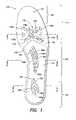
- FIG. 1is a top-plan view of the midsole insert of the present invention
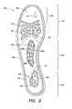
- FIG. 2is a bottom-plan view of the midsole insert of the present invention
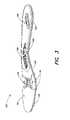
- FIG. 3is a side perspective view of the midsole insert of FIGS. 1–2 ;
- FIG. 4is a cross-sectional view of a shoe manufactured with the midsole insert of the present invention.
- FIG. 5is a cross-sectional view of the midsole insert taken along the line 5 — 5 of FIG. 1 ;
- FIG. 6is a cross-sectional view of the midsole insert taken along the line 6 — 6 of FIG. 1 ;
- FIG. 7is a cross-sectional view of the midsole insert taken along the line 7 — 7 of FIG. 1 .
- the energy return system of the present inventionincludes the use of components in the midsole region that provide both cushioning and energy return characteristics. These components may be selectively employed in the heel, midfoot, and/or the forefoot portions to provide the desired energy return characteristics for a particular type of shoe. These components may be especially designed for use in walking shoes or specific types of athletic shoes, such as basketball or running shoes. Further, the design of the midsole insert is a full footed design supporting the entire bottom of the wearer's foot. In one embodiment, the midsole insert is a single molded design featuring the grid energy return technology to address all phases of the gait cycle, and this new design replaces conventional running shoe designs which feature several components of midsole technology.
- the midsole insertis constructed and arranged to attach directly to an upper during a manufacturing step, to secure the shape of the upper on a last. As described in further detail below, this eliminates the need for a stroble board, which is typically used to secure the shape of the upper on a last in many conventional methods of shoe manufacturing. Also, as described in more detail below, the direct attachment of the midsole insert to the upper positions the energy return grid technology closer to the foot, this maximizing reaction time and performance.
- the midsole insert 100 in the assembled shoe 500lies between the outsole 200 and the upper 300 , as can be seen in FIG. 4 .
- the midsole insert 100 of this embodimentis attached directly to the upper 300 and the outsole 200 is affixed to the midsole insert 100 using any appropriate method, such as with any of a number of conventional adhesives and or stitching.
- a sock liner 400lies between the midsole 100 and the foot of the wearer (not shown), and the outsole 200 may have an additional tread layer 250 affixed to its bottom surface.
- the sock liner 400is constructed from a LYCRA® material that manages moisture in the shoe.
- the outsole 200may contain one material, or it may alternatively include several layers of different materials. It may also have an opening or recessed segment as illustrated at 22 in FIG. 3 of U.S. Pat. No. 5,402,588.
- the midsole insert 100may be formed of a single material, or it may be formed of more than one material.
- the midsole 100is made of two different portions, a center portion 110 and a peripheral portion 120 , each of which is made of a different material.
- the center and peripheral portions 110 , 120 of this embodimentwhile formed in separate steps and have different physical characteristics, they nevertheless comprise an integral midsole 100 .
- the center portion 110forms an inner part of the midsole insert 100 that extends from approximately the heel area 150 through approximately the midfoot area 160
- the peripheral portion 120forms the balance of the midsole insert 100 , encompassing a majority of the forefoot area 170 and the perimeter 180 of the midsole insert 100 .
- the midsole insert 100may be made of any suitable material, including plastics, rubbers, and natural or synthetic fabrics, as well as any suitable combination of such materials.
- a first materialis injection molded into the shape of the forefoot portion and the frame extending about the perimeter, and a second material is co-injected molded into the shape of the heel and midfoot portions, upon the first material.
- the midsole insert 100is constructed and arranged such that a conventional stroble board is not required in the shoe manufacturing process.
- athletic and walking shoesare manufactured by first forming and shaping the upper onto a last. The upper is then secured in this shape by attaching the upper to a stroble board along the bottom of the last.
- the upperis made with a seamless design, which may be created by fusing synthetic leather and breathable mesh parts, rather than stitching the components together. The fused upper eliminates the friction and irritation which may be caused by seams, layers, and threads.
- the stroble boardis typically constructed from a thin fiberboard material.
- any outsole and midsoleare secured, forming the shoe, and the stroble board is typically adhered to a portion of the sole of the shoe.
- the stroble boardhelps secure the shape of the upper, it would be advantageous to simplify the manufacturing process by eliminating the need for a stroble board.
- the present inventioncombines the function of a stroble board with the midsole technology, such that only one midsole insert is needed.
- the midsole insertIn addition to the ease of manufacturing, directly attaching the midsole insert to the upper enables the energy return grid technology to be positioned closer to the foot. In conventional shoe designs that feature some sort of grid system, the stroble board separated the grid from the foot. This arrangement of the present invention may maximize reaction time and overall performance.
- the midsole insert 100is attached directly to the upper 300 .
- the two componentsmay be attached in a variety of methods, such as stitched, sealed, cemented, etc.
- the embodiment shown in FIG. 4illustrates the midsole insert 100 stitched directly to the upper 300 in a zigzag chain stitch pattern about the perimeter of the midsole insert 100 .
- the direct attachment 302 of the upper 300 to the midsole insert 100is facilitated by constructing the midsole insert such that the thickness of the perimeter 180 is less than the thickness of the body of the midsole insert. This reduced thickness area allows for the upper to attach to the perimeter of the midsole insert more easily, especially if the components are stitched together.
- the reduced thickness perimeterdoes not compromise the rigidity or stability of the main body of the midsole insert.
- the direct attachment of the upper 300 to the midsole insert 100is further facilitated with a groove 130 that extends about at least a portion of the perimeter 180 of the midsole insert. As shown in FIG. 2 , the groove 130 may be more prominent on the bottom surface 102 of the insert.
- the various materials that make up the midsole 100can have varying physical compositions, so as to have physical characteristics (weight, strength, hardness, brittleness, etc.) that are most suited for the portion of the midsole 100 that they comprise.
- the center portion 110is made of a plastic that is harder than the plastic that makes up the peripheral portion 120 ; accordingly, the center portion provides more stability and rigidity in the heel and midfoot areas, while the peripheral portion provides more flexibility in the forefoot area and helps facilitate the stitching of the midsole 100 to the upper 300 .
- the durameter of the peripheral portion 120is approximately between 92–98A, and the durameter of the center portion 110 is approximately within the range of 57–63D.
- the durameter of the peripheral portion 120is about 95A and the durameter of the center portion 110 is about 60D.
- the center portion 110including both the midfoot and heel sections, is constructed of two thicknesses of PEBAX® material; one layer providing cushioning while the other layer provides support and torsional rigidity.
- the peripheral portion 120including both the forefoot and toe sections, is constructed of thermoplastic urethane, a polymer that provides support without inhibiting flexibility.
- the materials of the center and peripheral portions 110 , 120work in unison with the energy return grid systems to fluidly support the foot's natural motion.
- the run, or walkis smoother and more effortless.
- the materials that make up the midsole 100can be selected to have characteristics that best suit the particular type of shoe (running, walking, basketball, etc.) being constructed, and/or the particular individual or type of individual for whom the shoe is designed.
- the materialsmay also be of various colors, may be wholly or partially transparent, and may have any appropriate texture or other surface markings, so as to provide various aesthetic effects.
- the midsole insert 100is not flat, but rather has a gently cupped shape, so as to approximate the contour of the bottom of a foot.
- the cuppingis more pronounced in the heel and midfoot areas, where feet are generally more rounded, and less pronounced in the forefoot area, where feet are generally more flat.
- the amount of contourcan be varied to accommodate different shaped feet or gaits and to best suit a particular intended activity.
- the midsole insert 100may be highly rounded in the heel area 150 to provide stability.
- the midsole insert 100 of the embodiment illustrated in FIGS. 1–2is constructed in four zones to most efficiently respond to the four parts of the human gait cycle.
- the four zonescorrespond to the heel 150 , midfoot 160 , forefoot 170 , and toe 190 portions of the midsole insert, where the toe portion 190 may be part of the forefoot 170 portion.
- the heel area 150 of the midsole insert 100in one embodiment includes a heel opening 152 .
- a molded heel grid 156Extending across the heel opening 152 is a molded heel grid 156 that may have a slightly convex shape.
- the heel grid 156is integrally formed of the material that forms the center portion 110 .
- the gridmay be cut into the midsole insert. It should be appreciated, however, that the heel grid 156 may also made, in whole or in part, of a different material than the rest of the midsole 100 and may be formed independently of the midsole insert 100 , being applied or attached by any appropriate method.
- the heel grid 156is made up of a first set of ribs 158 a crossing a second set of ribs 158 b .
- the two sets of ribs 158 a , 158 bmay be integrally connected at their intersections 80 (such as when they are both integrally molded with a portion of the midsole insert 100 ), one may simply lie across the other, or they may be wholly or partially interwoven.
- the ribs 158 a , 158 b in the grid systemare suitably taut, thereby forming a spring-like member which is resilient. Therefore, the heel grid 156 is capable of deflection and return when impacted by the force of the heel of the foot.
- the gridsfunction as spring-like systems in selected areas of the midfoot insert for the purpose of storing energy in running and/or jumping during compression portions of the gait cycle and for releasing energy during the push-off phase of the gait cycle.
- the heel area 150may have a decoupled heel strike down area to lengthen the time of impact, to further provide cushioning, and to reduce the rate of pronation.
- the heel grid 156is arranged such that the first set of ribs 158 a generally run in the direction from the heel 150 to the forefoot 170 , while the second set of ribs generally run from the lateral to the medial side.
- Different grid patternsmay help to counter pronation.
- the ribs 158 a , 158 bare all flush with the top surface 101 of the midsole insert 100 , the thickness of the ribs 158 a , 158 b may vary. Additionally, at least a portion of the ribs may form ridges that protrude out from the bottom surface 102 of the midsole insert 100 . As shown in FIGS.
- the perimeter 159 of the heel grid 156protrudes from the bottom surface 102 of the midsole insert. It should be understood, of course, that this arrangement is merely illustrative and that other arrangements of the heel grid 156 fall within the scope of the invention. Also, as shown in FIGS. 1–2 and 5 , in one embodiment, the heel grid 156 is positioned offset from the centerline 90 of the midsole insert, closer to the medial side of the midsole insert.
- the heel opening 152 and heel grid 156 of this embodimentmay lie above a rear opening 210 in the outsole 200 , allowing the heel grid 156 to flex freely and allowing the heel grid 156 to be seen and perhaps touched from the bottom of the shoe.
- the outsole 200may include a heel insert (not shown) that partially or fully covers the rear opening 210 .
- the midfoot area 160 of the midsole insert 100also may include a midfoot opening 162 .
- a molded midfoot grid 166which may have a convex shape. Similar to the heel grid 156 , the midfoot grid 166 may either be integrally molded from the material that forms the center portion 110 , or it may be formed independently of the midsole insert and applied or attached separately. In one embodiment, the grid is cut into the midsole insert.
- the midfoot grid 166is made up of a first set of ribs 168 a crossing a second set of ribs 168 b which may be integrally connected at their intersections, or they may lie across each other, or they may be wholly or partially interwoven.
- the midfoot area 160may include a pronation phase having an angled medial side of the midsole to help reduce the angle of pronation.
- the midfoot area 160may also form a deep center channel to improve the support and stability of a foot in the shoe by keeping the foot centered in a more neutral position.
- the midfoot grid 166is similar to the heel grid 156 , the midfoot grid 166 typically provides greater torsion resistance, rigidity, and stability, in comparison to the heel grid 156 . These above characteristics are desirable in the midfoot section, to better control the movement of the arch of the foot. Increased torsion resistance, rigidity, and stability may be achieved by reducing the spacing between the ribs, increasing the overall size or thickness of the ribs, increasing the amount of material in the grid, and/or implementing a more rigid material in the grid. As shown in FIGS.
- the perimeter 169 of the midfoot grid, the second set of ribs 168 b , and some of the first set of ribs 168 aform ridges on the underside that protrude from the bottom of the midsole insert 100 , while some of the first set of ribs 168 a have a smaller thickness that do not protrude through the bottom surface 102 of the midsole insert 100 .
- the shape or pattern of the midfoot gridis not limited to a particular embodiment, it may be beneficial if the midfoot ribs are aligned such that the first set of ribs 168 a follow the shape of the adjacent contour of the medial side of midsole insert 100 , while some of the second set of ribs 168 b are aligned to extend at varying diagonals from the medial to the lateral side of the midsole insert. Further, it may be beneficial for all of the ribs to be flush with the top surface 101 of the midsole insert. Also, in one embodiment, the midfoot grid 166 is positioned offset from the centerline 90 of the midsole insert, closer to the medial side of the midsole insert.
- the midfoot opening 162 and midfoot grid 166lie above an opening 210 in the outsole 200 , allowing the midfoot grid 166 to flex freely and allowing the midfoot grid 166 to be seen and perhaps touched from the bottom of the shoe.
- the outsole 200may include an insert (not shown) that partially or fully covers the opening 210 .
- the midsole insert 100does not have a midfoot grid 166 .
- the midfoot area 160may contain a region of increased rigidity due to either an area of increased thickness and/or a more rigid material.
- the forefoot area 170 of the midsole insert 100also may include at least one forefoot opening 172 .
- Extending across the openingis a molded forefoot grid 176 which may have a convex shape.
- the forefoot grid 176may either be integrally molded from the material that forms the peripheral portion 120 , or it may be formed independently of the midsole insert and applied or attached separately. In one embodiment, the grid is cut into the midsole insert.
- the forefoot grid 176is made up of at least a first set of ribs 178 a crossing a second set of ribs 178 b which may be integrally connected at their intersections, or they may lie across each other, or they may be wholly or partially interwoven.
- the forefoot grid 176functions as spring-like system in selected areas for the purpose of storing energy in running and/or jumping during compression portions of the gait cycle and for releasing energy during the push-off phase of the gait cycle.
- the forefoot grid 176contains a third set of ribs 178 c which may provide more stability to the medial and lateral side of the midsole insert.
- the forefoot grid 176is shown in the figures as being centered on the centerline 90 of the midsole insert between the medial and lateral sides, in some embodiments, the grid may be offset to either side.
- the forefoot area 170may include medial and lateral forefoot voids, or areas where there are depressions on the top surface 101 of the midsole insert in the forefoot area to enhance forefoot cushioning and flexibility. Further, the toe section 190 of the forefoot area, may be angled to help align the foot in proper position.
- the forefoot grid 170design one can effectively achieve the desired amount of flexibility. Also, as discussed above, if the peripheral portion 120 is constructed from a material that is less rigid than the center portion 100 , the forefoot area 170 will be more flexible in comparison to the midfoot and heel areas.
- the shape or pattern of the forefoot gridis not limited to a particular embodiment, it may be beneficial if the forefoot ribs are aligned such that the first set of ribs 178 a follow a relatively linear path extending between the toe and heel portions, while the second set of ribs 178 b are aligned to extend between the medial side and the lateral side of the midsole insert. Further, it may be beneficial for all of the ribs to be flush with the top surface 101 of the midsole insert.
- the forefoot opening 172 and forefoot grid 176may lie above an opening 210 in the outsole 200 , allowing the forefoot grid 176 to flex freely and allowing the forefoot grid 176 to be seen and perhaps touched from the bottom of the shoe.
- the outsole 200may include an insert (not shown) that partially or fully covers the opening 210 .
- portions of the forefoot areamay protrude from the bottom of the midsole insert 100 .
- at least a portion of the rib 178 patternmay form ridges that protrude through the bottom surface 102 .
- a raised toe section 174also protrudes from the bottom surface of the insert in the toe portion 190 . This toe section 174 is positioned on the midsole insert to correspond with at least the large toe of a foot. This area of increased thickness provides additional support to the foot during the full gait cycle.
- another protrusionextends on the bottom side of the midsole insert to align and position the midsole insert with respect to a mold used to form the lattice pattern of the grid systems.
- This protrusionis not limited to a specific shape, although it is shown in one embodiment in FIG. 2 as a raised V-shaped section 192 formed on the underside of the forefoot portion.
Landscapes
- Engineering & Computer Science (AREA)
- Health & Medical Sciences (AREA)
- Epidemiology (AREA)
- General Health & Medical Sciences (AREA)
- Public Health (AREA)
- Chemical & Material Sciences (AREA)
- Materials Engineering (AREA)
- Mechanical Engineering (AREA)
- Footwear And Its Accessory, Manufacturing Method And Apparatuses (AREA)
Abstract
Description
Claims (26)
Priority Applications (2)
| Application Number | Priority Date | Filing Date | Title |
|---|---|---|---|
| US10/723,977US7207125B2 (en) | 2003-11-26 | 2003-11-26 | Grid midsole insert |
| PCT/US2004/034778WO2005055754A1 (en) | 2003-11-26 | 2004-10-21 | Grid midsole insert |
Applications Claiming Priority (1)
| Application Number | Priority Date | Filing Date | Title |
|---|---|---|---|
| US10/723,977US7207125B2 (en) | 2003-11-26 | 2003-11-26 | Grid midsole insert |
Publications (2)
| Publication Number | Publication Date |
|---|---|
| US20050108898A1 US20050108898A1 (en) | 2005-05-26 |
| US7207125B2true US7207125B2 (en) | 2007-04-24 |
Family
ID=34592447
Family Applications (1)
| Application Number | Title | Priority Date | Filing Date |
|---|---|---|---|
| US10/723,977Expired - Fee RelatedUS7207125B2 (en) | 2003-11-26 | 2003-11-26 | Grid midsole insert |
Country Status (2)
| Country | Link |
|---|---|
| US (1) | US7207125B2 (en) |
| WO (1) | WO2005055754A1 (en) |
Cited By (34)
| Publication number | Priority date | Publication date | Assignee | Title |
|---|---|---|---|---|
| US20090145004A1 (en)* | 2007-12-05 | 2009-06-11 | Saucony, Inc. | Stabilizer and cushioning support for athletic footwear |
| US20110209360A1 (en)* | 2010-03-01 | 2011-09-01 | Nike, Inc. | Footwear Insole |
| US8414811B1 (en)* | 2008-01-10 | 2013-04-09 | Jd & Sw, Llc | Moldable thermoplastic inserts |
| US8584380B2 (en) | 2010-02-23 | 2013-11-19 | Nike, Inc. | Self-adjusting studs |
| US8789296B2 (en) | 2010-02-18 | 2014-07-29 | Nike, Inc. | Self-adjusting studs |
| US9210967B2 (en) | 2010-08-13 | 2015-12-15 | Nike, Inc. | Sole structure with traction elements |
| US9320316B2 (en) | 2013-03-14 | 2016-04-26 | Under Armour, Inc. | 3D zonal compression shoe |
| US9351537B2 (en) | 2009-10-01 | 2016-05-31 | Nike, Inc. | Rigid cantilevered stud |
| US20160242502A1 (en)* | 2015-02-25 | 2016-08-25 | NIKE, lnc. | Article of Footwear With A Lattice Sole Structure |
| USD789060S1 (en) | 2016-03-04 | 2017-06-13 | Under Armour, Inc. | Shoe component |
| US10010133B2 (en) | 2015-05-08 | 2018-07-03 | Under Armour, Inc. | Midsole lattice with hollow tubes for footwear |
| US10010134B2 (en) | 2015-05-08 | 2018-07-03 | Under Armour, Inc. | Footwear with lattice midsole and compression insert |
| US10039343B2 (en) | 2015-05-08 | 2018-08-07 | Under Armour, Inc. | Footwear including sole assembly |
| US10455885B2 (en) | 2014-10-02 | 2019-10-29 | Adidas Ag | Flat weft-knitted upper for sports shoes |
| US10631591B2 (en) | 2017-05-23 | 2020-04-28 | Nike, Inc. | Sole structure for an article of footwear with undulating sole plate |
| US10779614B2 (en) | 2017-06-21 | 2020-09-22 | Under Armour, Inc. | Cushioning for a sole structure of performance footwear |
| US10834991B2 (en) | 2013-04-19 | 2020-11-17 | Adidas Ag | Shoe |
| US10856610B2 (en) | 2016-01-15 | 2020-12-08 | Hoe-Phuan Ng | Manual and dynamic shoe comfortness adjustment methods |
| US10864676B2 (en) | 2017-06-01 | 2020-12-15 | Nike, Inc. | Methods of manufacturing articles utilizing foam particles |
| US10939729B2 (en) | 2013-04-19 | 2021-03-09 | Adidas Ag | Knitted shoe upper |
| US11006695B2 (en) | 2018-05-31 | 2021-05-18 | Nike, Inc. | Footwear sole plate with forefoot through hole |
| US11044963B2 (en) | 2014-02-11 | 2021-06-29 | Adidas Ag | Soccer shoe |
| US11089834B2 (en) | 2018-05-31 | 2021-08-17 | Nike, Inc. | Footwear sole plate with non-parallel waves of varying thickness |
| US11401396B2 (en) | 2018-12-06 | 2022-08-02 | Nike, Inc. | Methods of manufacturing articles utilizing foam particles |
| US11589637B2 (en) | 2013-04-19 | 2023-02-28 | Adidas Ag | Layered shoe upper |
| US11617413B2 (en) | 2019-11-19 | 2023-04-04 | Nike, Inc. | Methods of manufacturing articles having foam particles |
| US11666113B2 (en) | 2013-04-19 | 2023-06-06 | Adidas Ag | Shoe with knitted outer sole |
| US11707108B2 (en) | 2012-04-13 | 2023-07-25 | Adidas Ag | Soles for sports shoes |
| US20240206588A1 (en)* | 2022-12-23 | 2024-06-27 | Saucony, Inc. | Article of footwear with sole plate |
| USD1035231S1 (en) | 2013-04-12 | 2024-07-16 | Adidas Ag | Shoe |
| US12082639B2 (en) | 2012-04-13 | 2024-09-10 | Adidas Ag | Shoe upper |
| US12245658B2 (en) | 2013-02-13 | 2025-03-11 | Adidas Ag | Cushioning element for sports apparel |
| US12250994B2 (en) | 2013-04-19 | 2025-03-18 | Adidas Ag | Shoe |
| US12342902B2 (en) | 2018-10-19 | 2025-07-01 | Nike, Inc. | Footwear sole structure having a composite element and methods for manufacturing same |
Families Citing this family (46)
| Publication number | Priority date | Publication date | Assignee | Title |
|---|---|---|---|---|
| US7571556B2 (en)* | 2004-12-28 | 2009-08-11 | Saucony, Inc. | Heel grid system |
| US20070214682A1 (en)* | 2006-03-17 | 2007-09-20 | Smotrycz Zenon O | Ventilated shoe sole construction with improved medical support |
| US8205357B2 (en)* | 2008-05-29 | 2012-06-26 | K-Swiss, Inc. | Interchangeable midsole system |
| US8616892B2 (en)* | 2009-04-02 | 2013-12-31 | Nike, Inc. | Training system for an article of footwear with a traction system |
| US8632342B2 (en) | 2009-05-28 | 2014-01-21 | Nike, Inc. | Training system for an article of footwear |
| US8573981B2 (en) | 2009-05-29 | 2013-11-05 | Nike, Inc. | Training system for an article of footwear with a ball control portion |
| DE102009028627B4 (en)* | 2009-08-18 | 2019-12-19 | Adidas Ag | Sports Shoe |
| US8529267B2 (en) | 2010-11-01 | 2013-09-10 | Nike, Inc. | Integrated training system for articles of footwear |
| US8555525B2 (en) | 2011-01-18 | 2013-10-15 | Saucony Ip Holdings Llc | Footwear |
| US8732982B2 (en)* | 2011-01-18 | 2014-05-27 | Saucony IP Holdings, LLC | Footwear |
| US8713819B2 (en) | 2011-01-19 | 2014-05-06 | Nike, Inc. | Composite sole structure |
| US20130067765A1 (en)* | 2011-09-16 | 2013-03-21 | Nike, Inc. | Article Of Footwear |
| US8966787B2 (en) | 2011-09-16 | 2015-03-03 | Nike, Inc. | Orientations for footwear ground-engaging member support features |
| US8806779B2 (en) | 2011-09-16 | 2014-08-19 | Nike, Inc. | Shaped support features for footwear ground-engaging members |
| US9220320B2 (en) | 2011-09-16 | 2015-12-29 | Nike, Inc. | Sole arrangement with ground-engaging member support features |
| US9138027B2 (en) | 2011-09-16 | 2015-09-22 | Nike, Inc. | Spacing for footwear ground-engaging member support features |
| US8595956B2 (en)* | 2011-09-29 | 2013-12-03 | C. & J. Clark International Limited | Footwear with elastic footbed cover and soft foam footbed |
| WO2013113338A1 (en)* | 2012-02-04 | 2013-08-08 | Puma SE | Shoe, particularly sports shoe |
| US9032645B2 (en) | 2012-07-30 | 2015-05-19 | Nike, Inc. | Support features for footwear ground engaging members |
| AU2013337597B2 (en)* | 2012-10-30 | 2017-03-02 | Graeme Scott Attey | Footwear sole structure with suspended elastomeric web or mesh support |
| DE102013202306B4 (en) | 2013-02-13 | 2014-12-18 | Adidas Ag | Sole for a shoe |
| US9930928B2 (en) | 2013-02-13 | 2018-04-03 | Adidas Ag | Sole for a shoe |
| US9610746B2 (en) | 2013-02-13 | 2017-04-04 | Adidas Ag | Methods for manufacturing cushioning elements for sports apparel |
| DE102013002519B4 (en) | 2013-02-13 | 2016-08-18 | Adidas Ag | Production method for damping elements for sportswear |
| USD740004S1 (en) | 2013-04-12 | 2015-10-06 | Adidas Ag | Shoe |
| GB2524261A (en) | 2014-03-18 | 2015-09-23 | Univ Staffordshire | Improvements in or relating to footwear |
| US9474326B2 (en)* | 2014-07-11 | 2016-10-25 | Nike, Inc. | Footwear having auxetic structures with controlled properties |
| DE102014215897B4 (en) | 2014-08-11 | 2016-12-22 | Adidas Ag | adistar boost |
| DE102014216115B4 (en) | 2014-08-13 | 2022-03-31 | Adidas Ag | 3D elements cast together |
| DE102015206486B4 (en) | 2015-04-10 | 2023-06-01 | Adidas Ag | Shoe, in particular sports shoe, and method for manufacturing the same |
| DE102015206900B4 (en) | 2015-04-16 | 2023-07-27 | Adidas Ag | sports shoe |
| DE102015209795B4 (en) | 2015-05-28 | 2024-03-21 | Adidas Ag | Ball and process for its production |
| EP3340829B1 (en)* | 2015-08-25 | 2020-07-29 | Nike Innovate C.V. | Footwear sole structure with carrier and frame |
| USD783264S1 (en) | 2015-09-15 | 2017-04-11 | Adidas Ag | Shoe |
| USD840137S1 (en) | 2016-08-03 | 2019-02-12 | Adidas Ag | Shoe midsole |
| USD840136S1 (en) | 2016-08-03 | 2019-02-12 | Adidas Ag | Shoe midsole |
| USD852475S1 (en) | 2016-08-17 | 2019-07-02 | Adidas Ag | Shoe |
| JP1582717S (en) | 2016-09-02 | 2017-07-31 | ||
| US10952496B2 (en)* | 2017-05-09 | 2021-03-23 | Under Armour, Inc. | Article of footwear with interlocking midsole member |
| USD899061S1 (en) | 2017-10-05 | 2020-10-20 | Adidas Ag | Shoe |
| DE102019204579B4 (en) | 2019-04-01 | 2022-10-06 | Adidas Ag | Recycling a shoe |
| NL2023135B1 (en)* | 2019-05-15 | 2020-12-01 | Anbo Amersfoort B V | Shoe sole assembly, shoe, and method of manufacturing a shoe |
| US11297897B2 (en)* | 2019-11-27 | 2022-04-12 | Cole Haan Llc | Shoe with multiple material sole |
| KR102263757B1 (en)* | 2019-12-09 | 2021-06-11 | 문신환 | Porous Midsole Manufacturing Method and Porous Midsole Using It |
| KR20230047997A (en)* | 2020-06-08 | 2023-04-10 | 애리스 컴포지트 아이엔씨. | Textile-composite-reinforced footwear |
| DE102023201065A1 (en)* | 2023-02-09 | 2024-08-14 | Adidas Ag | Outsole for a shoe |
Citations (44)
| Publication number | Priority date | Publication date | Assignee | Title |
|---|---|---|---|---|
| US812496A (en) | 1903-11-04 | 1906-02-13 | Herbert E Irwin | Resilient heel and sole. |
| US1650466A (en) | 1926-10-16 | 1927-11-22 | James B Righter | Cushion lift for shoes |
| US2347207A (en)* | 1940-11-22 | 1944-04-25 | Margolin Meyer | Ventilated insole |
| US3426455A (en)* | 1965-06-25 | 1969-02-11 | Superga Spa | Shoe insole |
| US3481820A (en)* | 1963-05-17 | 1969-12-02 | Genesco Inc | Shoe manufacture |
| US4297796A (en) | 1979-07-23 | 1981-11-03 | Stirtz Ronald H | Shoe with three-dimensionally transmitting shock-absorbing mechanism |
| US4398357A (en)* | 1981-06-01 | 1983-08-16 | Stride Rite International, Ltd. | Outsole |
| US4594799A (en)* | 1984-12-10 | 1986-06-17 | Autry Industries, Inc. | Tennis shoe construction |
| US4608768A (en) | 1983-10-24 | 1986-09-02 | Puma-Sportschuhfabriken Rudolf Dassler Kg | Athletic shoe having a shock-absorbing running sole and a process for manufacturing said athletic shoe |
| US4733483A (en) | 1987-02-20 | 1988-03-29 | Autry Industries, Inc. | Custom midsole |
| US4739765A (en)* | 1985-06-28 | 1988-04-26 | Bio Balance Orthotics Inc. | Arch support |
| US4815221A (en) | 1987-02-06 | 1989-03-28 | Reebok International Ltd. | Shoe with energy control system |
| US4878301A (en) | 1987-06-25 | 1989-11-07 | Asics Corporation | Sports shoe |
| GB2243530A (en) | 1990-09-13 | 1991-11-06 | Gola Group Plc | Footwear |
| US5070629A (en) | 1989-10-26 | 1991-12-10 | Hyde Athletic Industries, Inc. | Sweet spot sole construction |
| US5255451A (en) | 1988-12-14 | 1993-10-26 | Avia Group International, Inc. | Insert member for use in an athletic shoe |
| US5402588A (en) | 1989-10-26 | 1995-04-04 | Hyde Athletic Industries, Inc. | Sole construction |
| US5469639A (en) | 1994-12-02 | 1995-11-28 | Sessa; Raymond V. | Shoe sole having insert with graduated cushioning properties |
| US5561920A (en) | 1989-10-26 | 1996-10-08 | Hyde Athletic Industries, Inc. | Shoe construction having an energy return system |
| US5588226A (en) | 1995-02-17 | 1996-12-31 | Schenkel; Decio L. | Unidirectional air transfer system for shoes |
| US5595002A (en) | 1994-12-05 | 1997-01-21 | Hyde Athletic Industries, Inc. | Stabilizing grid wedge system for providing motion control and cushioning |
| EP0795280A2 (en) | 1996-03-15 | 1997-09-17 | Shimano Inc. | Cycling shoe core, molding method and molding apparatus for same |
| US5718063A (en) | 1995-07-17 | 1998-02-17 | Asics Corporation | Midsole cushioning system |
| US5722186A (en)* | 1990-02-16 | 1998-03-03 | Northwest Podiatric Laboratory, Inc. | Orthotic insert having adjustable angular orientation |
| US5839208A (en)* | 1997-04-18 | 1998-11-24 | Ho-Tai Industrial Co. | Resilient sole for shoe |
| US5852886A (en) | 1996-01-04 | 1998-12-29 | Hyde Athletics Industries, Inc. | Combination midsole stabilizer and enhancer |
| US5983529A (en) | 1997-07-31 | 1999-11-16 | Vans, Inc. | Footwear shock absorbing system |
| US6006449A (en) | 1998-01-29 | 1999-12-28 | Precision Products Group, Inc. | Footwear having spring assemblies in the soles thereof |
| US6038790A (en) | 1998-02-26 | 2000-03-21 | Nine West Group, Inc. | Flexible sole with cushioned ball and/or heel regions |
| US6205683B1 (en) | 1997-05-30 | 2001-03-27 | The Timberland Company | Shock diffusing, performance-oriented shoes |
| US6216365B1 (en) | 1998-11-05 | 2001-04-17 | Springco, Ltd. | Shock-absorbing insole |
| US6231946B1 (en) | 1999-01-15 | 2001-05-15 | Gordon L. Brown, Jr. | Structural reinforcement for use in a shoe sole |
| US20020017036A1 (en) | 2000-07-25 | 2002-02-14 | Christoph Berger | Climate configurable sole and shoe |
| US6408544B1 (en) | 1999-07-02 | 2002-06-25 | Bbc International Ltd. | Flex sole |
| US6418641B1 (en) | 1998-02-11 | 2002-07-16 | Decio Luiz Schenkel | Sport shoe with structural frame |
| US20020092202A1 (en) | 2001-01-12 | 2002-07-18 | Salomon S.A. | Intermediary sole and shoe equipped with such a sole |
| US20020092203A1 (en) | 2001-01-17 | 2002-07-18 | Hardt John C. | Insole with rebounding and cushioning areas and adjustable arch support |
| US6438870B2 (en) | 1998-11-05 | 2002-08-27 | Asics Corporation | Shoe sole with shock absorber structure |
| US6467197B1 (en) | 1999-05-31 | 2002-10-22 | Asics Corp. | Shoe with arch reinforcement |
| US6601321B1 (en) | 2000-05-04 | 2003-08-05 | Michael Kendall | Devices for suspending a foot within a shoe, and shoes incorporating such devices |
| US20030145487A1 (en)* | 2002-02-05 | 2003-08-07 | Dick Hong | Shoe pad with a gas discharging valve |
| US6655048B2 (en)* | 2000-10-31 | 2003-12-02 | Geox S.P.A. | Breathable and waterproof sole for shoes |
| US6681501B1 (en)* | 2002-09-24 | 2004-01-27 | Dr.'s Own, Inc. | Arch support device |
| US20040020075A1 (en)* | 2002-08-01 | 2004-02-05 | Louis Garneau Sport Inc. | Bicycle shoe with ventilating sole |
Family Cites Families (1)
| Publication number | Priority date | Publication date | Assignee | Title |
|---|---|---|---|---|
| US512496A (en)* | 1894-01-09 | Histological case |
- 2003
- 2003-11-26USUS10/723,977patent/US7207125B2/ennot_activeExpired - Fee Related
- 2004
- 2004-10-21WOPCT/US2004/034778patent/WO2005055754A1/enactiveApplication Filing
Patent Citations (46)
| Publication number | Priority date | Publication date | Assignee | Title |
|---|---|---|---|---|
| US812496A (en) | 1903-11-04 | 1906-02-13 | Herbert E Irwin | Resilient heel and sole. |
| US1650466A (en) | 1926-10-16 | 1927-11-22 | James B Righter | Cushion lift for shoes |
| US2347207A (en)* | 1940-11-22 | 1944-04-25 | Margolin Meyer | Ventilated insole |
| US3481820A (en)* | 1963-05-17 | 1969-12-02 | Genesco Inc | Shoe manufacture |
| US3426455A (en)* | 1965-06-25 | 1969-02-11 | Superga Spa | Shoe insole |
| US4297796A (en) | 1979-07-23 | 1981-11-03 | Stirtz Ronald H | Shoe with three-dimensionally transmitting shock-absorbing mechanism |
| US4398357A (en)* | 1981-06-01 | 1983-08-16 | Stride Rite International, Ltd. | Outsole |
| US4608768A (en) | 1983-10-24 | 1986-09-02 | Puma-Sportschuhfabriken Rudolf Dassler Kg | Athletic shoe having a shock-absorbing running sole and a process for manufacturing said athletic shoe |
| US4594799A (en)* | 1984-12-10 | 1986-06-17 | Autry Industries, Inc. | Tennis shoe construction |
| US4739765A (en)* | 1985-06-28 | 1988-04-26 | Bio Balance Orthotics Inc. | Arch support |
| US4815221A (en) | 1987-02-06 | 1989-03-28 | Reebok International Ltd. | Shoe with energy control system |
| US4733483A (en) | 1987-02-20 | 1988-03-29 | Autry Industries, Inc. | Custom midsole |
| US4878301A (en) | 1987-06-25 | 1989-11-07 | Asics Corporation | Sports shoe |
| US5255451A (en) | 1988-12-14 | 1993-10-26 | Avia Group International, Inc. | Insert member for use in an athletic shoe |
| US5070629A (en) | 1989-10-26 | 1991-12-10 | Hyde Athletic Industries, Inc. | Sweet spot sole construction |
| US5402588A (en) | 1989-10-26 | 1995-04-04 | Hyde Athletic Industries, Inc. | Sole construction |
| US5561920A (en) | 1989-10-26 | 1996-10-08 | Hyde Athletic Industries, Inc. | Shoe construction having an energy return system |
| US5722186A (en)* | 1990-02-16 | 1998-03-03 | Northwest Podiatric Laboratory, Inc. | Orthotic insert having adjustable angular orientation |
| GB2243530A (en) | 1990-09-13 | 1991-11-06 | Gola Group Plc | Footwear |
| US5469639A (en) | 1994-12-02 | 1995-11-28 | Sessa; Raymond V. | Shoe sole having insert with graduated cushioning properties |
| US5595002A (en) | 1994-12-05 | 1997-01-21 | Hyde Athletic Industries, Inc. | Stabilizing grid wedge system for providing motion control and cushioning |
| US5588226A (en) | 1995-02-17 | 1996-12-31 | Schenkel; Decio L. | Unidirectional air transfer system for shoes |
| US5718063A (en) | 1995-07-17 | 1998-02-17 | Asics Corporation | Midsole cushioning system |
| US5852886A (en) | 1996-01-04 | 1998-12-29 | Hyde Athletics Industries, Inc. | Combination midsole stabilizer and enhancer |
| US5974695A (en) | 1996-01-04 | 1999-11-02 | Slepian; Neil | Combination midsole stabilizer and enhancer |
| EP0795280A2 (en) | 1996-03-15 | 1997-09-17 | Shimano Inc. | Cycling shoe core, molding method and molding apparatus for same |
| US5839208A (en)* | 1997-04-18 | 1998-11-24 | Ho-Tai Industrial Co. | Resilient sole for shoe |
| US6205683B1 (en) | 1997-05-30 | 2001-03-27 | The Timberland Company | Shock diffusing, performance-oriented shoes |
| US5983529A (en) | 1997-07-31 | 1999-11-16 | Vans, Inc. | Footwear shock absorbing system |
| US6006449A (en) | 1998-01-29 | 1999-12-28 | Precision Products Group, Inc. | Footwear having spring assemblies in the soles thereof |
| US6418641B1 (en) | 1998-02-11 | 2002-07-16 | Decio Luiz Schenkel | Sport shoe with structural frame |
| US6038790A (en) | 1998-02-26 | 2000-03-21 | Nine West Group, Inc. | Flexible sole with cushioned ball and/or heel regions |
| US6216365B1 (en) | 1998-11-05 | 2001-04-17 | Springco, Ltd. | Shock-absorbing insole |
| US6438870B2 (en) | 1998-11-05 | 2002-08-27 | Asics Corporation | Shoe sole with shock absorber structure |
| US6231946B1 (en) | 1999-01-15 | 2001-05-15 | Gordon L. Brown, Jr. | Structural reinforcement for use in a shoe sole |
| US6467197B1 (en) | 1999-05-31 | 2002-10-22 | Asics Corp. | Shoe with arch reinforcement |
| US6408544B1 (en) | 1999-07-02 | 2002-06-25 | Bbc International Ltd. | Flex sole |
| US6601321B1 (en) | 2000-05-04 | 2003-08-05 | Michael Kendall | Devices for suspending a foot within a shoe, and shoes incorporating such devices |
| US20020017036A1 (en) | 2000-07-25 | 2002-02-14 | Christoph Berger | Climate configurable sole and shoe |
| EP1197157A1 (en) | 2000-07-25 | 2002-04-17 | adidas International B.V. | Shoe |
| US6655048B2 (en)* | 2000-10-31 | 2003-12-02 | Geox S.P.A. | Breathable and waterproof sole for shoes |
| US20020092202A1 (en) | 2001-01-12 | 2002-07-18 | Salomon S.A. | Intermediary sole and shoe equipped with such a sole |
| US20020092203A1 (en) | 2001-01-17 | 2002-07-18 | Hardt John C. | Insole with rebounding and cushioning areas and adjustable arch support |
| US20030145487A1 (en)* | 2002-02-05 | 2003-08-07 | Dick Hong | Shoe pad with a gas discharging valve |
| US20040020075A1 (en)* | 2002-08-01 | 2004-02-05 | Louis Garneau Sport Inc. | Bicycle shoe with ventilating sole |
| US6681501B1 (en)* | 2002-09-24 | 2004-01-27 | Dr.'s Own, Inc. | Arch support device |
Non-Patent Citations (2)
| Title |
|---|
| Internnational Search Report for PCT/US2004/034778. |
| Written Opinion of International Searching Authority for PCT/US2004/034778. |
Cited By (77)
| Publication number | Priority date | Publication date | Assignee | Title |
|---|---|---|---|---|
| US20090145004A1 (en)* | 2007-12-05 | 2009-06-11 | Saucony, Inc. | Stabilizer and cushioning support for athletic footwear |
| US8414811B1 (en)* | 2008-01-10 | 2013-04-09 | Jd & Sw, Llc | Moldable thermoplastic inserts |
| US8840825B2 (en) | 2008-01-10 | 2014-09-23 | JD & SW, LLC, (Nevada LLC) | Moldable thermoplastic inserts |
| US9351537B2 (en) | 2009-10-01 | 2016-05-31 | Nike, Inc. | Rigid cantilevered stud |
| US11076659B2 (en) | 2009-10-01 | 2021-08-03 | Nike, Inc. | Rigid cantilevered stud |
| US8789296B2 (en) | 2010-02-18 | 2014-07-29 | Nike, Inc. | Self-adjusting studs |
| US8584380B2 (en) | 2010-02-23 | 2013-11-19 | Nike, Inc. | Self-adjusting studs |
| US9451806B2 (en) | 2010-03-01 | 2016-09-27 | Nike, Inc. | Footwear insole |
| US20110209360A1 (en)* | 2010-03-01 | 2011-09-01 | Nike, Inc. | Footwear Insole |
| US9210967B2 (en) | 2010-08-13 | 2015-12-15 | Nike, Inc. | Sole structure with traction elements |
| US11707108B2 (en) | 2012-04-13 | 2023-07-25 | Adidas Ag | Soles for sports shoes |
| US12268271B2 (en) | 2012-04-13 | 2025-04-08 | Adidas Ag | Shoe upper |
| US12082639B2 (en) | 2012-04-13 | 2024-09-10 | Adidas Ag | Shoe upper |
| US12245658B2 (en) | 2013-02-13 | 2025-03-11 | Adidas Ag | Cushioning element for sports apparel |
| US11425963B2 (en) | 2013-03-14 | 2022-08-30 | Under Armour, Inc. | Shoe with lattice structure |
| US11547177B2 (en) | 2013-03-14 | 2023-01-10 | Under Armour, Inc. | Shoe with lattice structure |
| US10226098B2 (en) | 2013-03-14 | 2019-03-12 | Under Armour, Inc. | Method of making a zonal compression shoe |
| US10743610B2 (en) | 2013-03-14 | 2020-08-18 | Under Armour, Inc. | Shoe with lattice structure |
| US9320316B2 (en) | 2013-03-14 | 2016-04-26 | Under Armour, Inc. | 3D zonal compression shoe |
| US10470519B2 (en) | 2013-03-14 | 2019-11-12 | Under Armour, Inc. | Shoe with lattice structure |
| US10470520B2 (en) | 2013-03-14 | 2019-11-12 | Under Armour, Inc. | Shoe with lattice structure |
| US10575586B2 (en) | 2013-03-14 | 2020-03-03 | Under Armour, Inc. | Shoe with lattice structure |
| USD1035231S1 (en) | 2013-04-12 | 2024-07-16 | Adidas Ag | Shoe |
| US11896083B2 (en) | 2013-04-19 | 2024-02-13 | Adidas Ag | Knitted shoe upper |
| US11678712B2 (en) | 2013-04-19 | 2023-06-20 | Adidas Ag | Shoe |
| US11666113B2 (en) | 2013-04-19 | 2023-06-06 | Adidas Ag | Shoe with knitted outer sole |
| US11589637B2 (en) | 2013-04-19 | 2023-02-28 | Adidas Ag | Layered shoe upper |
| US12250994B2 (en) | 2013-04-19 | 2025-03-18 | Adidas Ag | Shoe |
| US10834991B2 (en) | 2013-04-19 | 2020-11-17 | Adidas Ag | Shoe |
| US10834992B2 (en) | 2013-04-19 | 2020-11-17 | Adidas Ag | Shoe |
| US11129433B2 (en) | 2013-04-19 | 2021-09-28 | Adidas Ag | Shoe |
| US10939729B2 (en) | 2013-04-19 | 2021-03-09 | Adidas Ag | Knitted shoe upper |
| US11116275B2 (en) | 2013-04-19 | 2021-09-14 | Adidas Ag | Shoe |
| US12376647B2 (en) | 2013-04-19 | 2025-08-05 | Adidas Ag | Knitted shoe upper |
| US11044963B2 (en) | 2014-02-11 | 2021-06-29 | Adidas Ag | Soccer shoe |
| US12369675B2 (en) | 2014-02-11 | 2025-07-29 | Adidas Ag | Soccer shoe |
| US10455885B2 (en) | 2014-10-02 | 2019-10-29 | Adidas Ag | Flat weft-knitted upper for sports shoes |
| US12220017B2 (en) | 2014-10-02 | 2025-02-11 | Adidas Ag | Flat weft-knitted upper for sports shoes |
| US11849796B2 (en) | 2014-10-02 | 2023-12-26 | Adidas Ag | Flat weft-knitted upper for sports shoes |
| US11272754B2 (en) | 2014-10-02 | 2022-03-15 | Adidas Ag | Flat weft-knitted upper for sports shoes |
| US20160242502A1 (en)* | 2015-02-25 | 2016-08-25 | NIKE, lnc. | Article of Footwear With A Lattice Sole Structure |
| US10143266B2 (en)* | 2015-02-25 | 2018-12-04 | Nike, Inc. | Article of footwear with a lattice sole structure |
| US11369164B2 (en) | 2015-05-08 | 2022-06-28 | Under Armour, Inc. | Footwear including sole assembly |
| US10039343B2 (en) | 2015-05-08 | 2018-08-07 | Under Armour, Inc. | Footwear including sole assembly |
| US10010134B2 (en) | 2015-05-08 | 2018-07-03 | Under Armour, Inc. | Footwear with lattice midsole and compression insert |
| US10575587B2 (en) | 2015-05-08 | 2020-03-03 | Under Armour, Inc. | Footwear including sole assembly |
| US10104934B2 (en) | 2015-05-08 | 2018-10-23 | Under Armour, Inc. | Footwear including sole assembly |
| US10010133B2 (en) | 2015-05-08 | 2018-07-03 | Under Armour, Inc. | Midsole lattice with hollow tubes for footwear |
| US11457693B2 (en) | 2015-05-08 | 2022-10-04 | Under Armour, Inc. | Footwear midsole with lattice structure formed between platforms |
| US11986049B2 (en) | 2015-05-08 | 2024-05-21 | Under Armour, Inc. | Footwear midsole with lattice structure formed between platforms |
| US10231511B2 (en) | 2015-05-08 | 2019-03-19 | Under Armour, Inc. | Interwoven lattice structure for cushioning member |
| US10750820B2 (en) | 2015-05-08 | 2020-08-25 | Under Armour, Inc. | Midsole lattice with hollow tubes for footwear |
| US12369684B2 (en) | 2015-05-08 | 2025-07-29 | Under Armour, Inc. | Footwear midsole with lattice structure formed between platforms |
| US10702012B2 (en) | 2015-05-08 | 2020-07-07 | Under Armour, Inc. | Footwear midsole with lattice structure formed between platforms |
| US10856610B2 (en) | 2016-01-15 | 2020-12-08 | Hoe-Phuan Ng | Manual and dynamic shoe comfortness adjustment methods |
| US11478043B2 (en) | 2016-01-15 | 2022-10-25 | Hoe-Phuan Ng | Manual and dynamic shoe comfortness adjustment methods |
| USD789060S1 (en) | 2016-03-04 | 2017-06-13 | Under Armour, Inc. | Shoe component |
| US10631591B2 (en) | 2017-05-23 | 2020-04-28 | Nike, Inc. | Sole structure for an article of footwear with undulating sole plate |
| US10974447B2 (en) | 2017-06-01 | 2021-04-13 | Nike, Inc. | Methods of manufacturing articles utilizing foam particles |
| US11833747B2 (en) | 2017-06-01 | 2023-12-05 | Nike, Inc. | Methods of manufacturing articles utilizing foam particles |
| US11884005B2 (en) | 2017-06-01 | 2024-01-30 | Nike, Inc. | Methods of manufacturing articles utilizing foam particles |
| US11806924B2 (en) | 2017-06-01 | 2023-11-07 | Nike, Inc. | Methods of manufacturing articles utilizing foam particles |
| US11090863B2 (en) | 2017-06-01 | 2021-08-17 | Nike, Inc. | Methods of manufacturing articles utilizing foam particles |
| US12269208B2 (en) | 2017-06-01 | 2025-04-08 | Nike, Inc. | Methods of manufacturing articles utilizing foam particles |
| US11241826B2 (en) | 2017-06-01 | 2022-02-08 | Nike, Inc. | Methods of manufacturing articles utilizing foam particles |
| US10864676B2 (en) | 2017-06-01 | 2020-12-15 | Nike, Inc. | Methods of manufacturing articles utilizing foam particles |
| US10946583B2 (en) | 2017-06-01 | 2021-03-16 | Nike, Inc. | Methods of manufacturing articles utilizing foam particles |
| US10779614B2 (en) | 2017-06-21 | 2020-09-22 | Under Armour, Inc. | Cushioning for a sole structure of performance footwear |
| US11089834B2 (en) | 2018-05-31 | 2021-08-17 | Nike, Inc. | Footwear sole plate with non-parallel waves of varying thickness |
| US11006695B2 (en) | 2018-05-31 | 2021-05-18 | Nike, Inc. | Footwear sole plate with forefoot through hole |
| US12342902B2 (en) | 2018-10-19 | 2025-07-01 | Nike, Inc. | Footwear sole structure having a composite element and methods for manufacturing same |
| US11981788B2 (en) | 2018-12-06 | 2024-05-14 | Nike, Inc. | Methods of manufacturing articles utilizing foam particles |
| US11401396B2 (en) | 2018-12-06 | 2022-08-02 | Nike, Inc. | Methods of manufacturing articles utilizing foam particles |
| US11840615B2 (en) | 2018-12-06 | 2023-12-12 | Nike, Inc. | Methods of manufacturing articles utilizing foam particles |
| US11732102B2 (en) | 2018-12-06 | 2023-08-22 | Nike, Inc. | Methods of manufacturing articles utilizing foam particles |
| US11617413B2 (en) | 2019-11-19 | 2023-04-04 | Nike, Inc. | Methods of manufacturing articles having foam particles |
| US20240206588A1 (en)* | 2022-12-23 | 2024-06-27 | Saucony, Inc. | Article of footwear with sole plate |
Also Published As
| Publication number | Publication date |
|---|---|
| US20050108898A1 (en) | 2005-05-26 |
| WO2005055754A1 (en) | 2005-06-23 |
Similar Documents
| Publication | Publication Date | Title |
|---|---|---|
| US7207125B2 (en) | Grid midsole insert | |
| US10561198B2 (en) | Footwear including lightweight sole structure providing enhanced comfort, flexibility and performance features | |
| US10624420B2 (en) | Article of footwear, elements thereof, and related methods of manufacturing | |
| EP1954154B1 (en) | Flexible shank for an article of footwear | |
| EP2286684B1 (en) | Outsole and sports shoe | |
| CN106659266B (en) | Article of footwear having a roll midsole with embedded elastic plate | |
| US8225534B2 (en) | Article of footwear with a flexible arch support | |
| US9687042B2 (en) | Article of footwear with a midsole structure | |
| US10834990B2 (en) | Foot support members that provide dynamically transformative properties | |
| US8181365B2 (en) | Article of footwear including improved heel structure | |
| CN104799484B (en) | Article of footwear with footwear front panel | |
| US5575089A (en) | Composite shoe construction | |
| CN105744851A (en) | Article of footwear having a sole structure with side stiffener | |
| US11439199B2 (en) | Footwear sole assembly | |
| US20230058209A1 (en) | Article of footwear | |
| US20140290098A1 (en) | Sole assembly for article of footwear | |
| US20170238658A1 (en) | Footwear Upper With Zonal Support Areas | |
| JP2019033797A (en) | Shoe | |
| US20190380434A1 (en) | Sole structure | |
| US20170251762A1 (en) | Footwear Upper With Ribbed Panels | |
| US12290136B2 (en) | Sole and shoe including same | |
| CN113925256A (en) | Shoe with net sole structure | |
| HK40058746A (en) | Footwear with mesh sole construction | |
| GB2515133B (en) | Article of footwear, elements thereof, and related methods of manufacturing |
Legal Events
| Date | Code | Title | Description |
|---|---|---|---|
| AS | Assignment | Owner name:SAUCONY, INC., MASSACHUSETTS Free format text:ASSIGNMENT OF ASSIGNORS INTEREST;ASSIGNORS:JEPPESEN, MICHAEL;AZEVEDO, AARON;DUFFY, GREGG;REEL/FRAME:015754/0958;SIGNING DATES FROM 20040726 TO 20040817 | |
| AS | Assignment | Owner name:WELLS FARGO RETAIL FINANCE, LLC, AS AGENT, MASSACH Free format text:SECURITY AGREEMENT;ASSIGNORS:PAYLESS SHOESOURCE, INC.;PAYLESS SHOESOURCE WORLDWIDE, INC.;SAUCONY, INC.;AND OTHERS;REEL/FRAME:020083/0830 Effective date:20070817 | |
| FEPP | Fee payment procedure | Free format text:PAYOR NUMBER ASSIGNED (ORIGINAL EVENT CODE: ASPN); ENTITY STATUS OF PATENT OWNER: LARGE ENTITY | |
| AS | Assignment | Owner name:CITICORP NORTH AMERICA, INC., NEW YORK Free format text:PATENT SECURITY AGREEMENT;ASSIGNORS:COLLECTIVE LICENSING INTERNATIONAL, LLC;PAYLESS SHOESOURCE WORLDWIDE, INC.;SAUCONY, INC.;AND OTHERS;REEL/FRAME:020845/0889 Effective date:20070417 | |
| REMI | Maintenance fee reminder mailed | ||
| LAPS | Lapse for failure to pay maintenance fees | ||
| STCH | Information on status: patent discontinuation | Free format text:PATENT EXPIRED DUE TO NONPAYMENT OF MAINTENANCE FEES UNDER 37 CFR 1.362 | |
| FP | Lapsed due to failure to pay maintenance fee | Effective date:20110424 | |
| AS | Assignment | Owner name:PAYLESS SHOESOURCE WORLDWIDE, INC., KANSAS Free format text:RELEASE OF SECURITY INTEREST IN PATENTS RECORDED AT REEL/FRAME 020845/0889;ASSIGNOR:CITICORP NORTH AMERICA, INC.;REEL/FRAME:029100/0383 Effective date:20121009 Owner name:SAUCONY, INC., MASSACHUSETTS Free format text:RELEASE OF SECURITY INTEREST IN PATENTS RECORDED AT REEL/FRAME 020845/0889;ASSIGNOR:CITICORP NORTH AMERICA, INC.;REEL/FRAME:029100/0383 Effective date:20121009 Owner name:SRL, INC., MASSACHUSETTS Free format text:RELEASE OF SECURITY INTEREST IN PATENTS RECORDED AT REEL/FRAME 020083/0830;ASSIGNOR:WELLS FARGO BANK, NATIONAL ASSOCIATION (A SUCCESSOR BY MERGER TO WELLS FARGO RETAIL FINANCE, LLC);REEL/FRAME:029100/0351 Effective date:20121009 Owner name:PAYLESS SHOESOURCE, INC., KANSAS Free format text:RELEASE OF SECURITY INTEREST IN PATENTS RECORDED AT REEL/FRAME 020083/0830;ASSIGNOR:WELLS FARGO BANK, NATIONAL ASSOCIATION (A SUCCESSOR BY MERGER TO WELLS FARGO RETAIL FINANCE, LLC);REEL/FRAME:029100/0351 Effective date:20121009 Owner name:SAN JOSE ACQUISITION CORP., KANSAS Free format text:RELEASE OF SECURITY INTEREST IN PATENTS RECORDED AT REEL/FRAME 020845/0889;ASSIGNOR:CITICORP NORTH AMERICA, INC.;REEL/FRAME:029100/0383 Effective date:20121009 Owner name:COLLECTIVE LICENSING INTERNATIONAL, LLC, KANSAS Free format text:RELEASE OF SECURITY INTEREST IN PATENTS RECORDED AT REEL/FRAME 020845/0889;ASSIGNOR:CITICORP NORTH AMERICA, INC.;REEL/FRAME:029100/0383 Effective date:20121009 Owner name:SRL, INC., MASSACHUSETTS Free format text:RELEASE OF SECURITY INTEREST IN PATENTS RECORDED AT REEL/FRAME 020845/0889;ASSIGNOR:CITICORP NORTH AMERICA, INC.;REEL/FRAME:029100/0383 Effective date:20121009 Owner name:SAUCONY, INC., MASSACHUSETTS Free format text:RELEASE OF SECURITY INTEREST IN PATENTS RECORDED AT REEL/FRAME 020083/0830;ASSIGNOR:WELLS FARGO BANK, NATIONAL ASSOCIATION (A SUCCESSOR BY MERGER TO WELLS FARGO RETAIL FINANCE, LLC);REEL/FRAME:029100/0351 Effective date:20121009 Owner name:SR HOLDINGS INC., KANSAS Free format text:RELEASE OF SECURITY INTEREST IN PATENTS RECORDED AT REEL/FRAME 020845/0889;ASSIGNOR:CITICORP NORTH AMERICA, INC.;REEL/FRAME:029100/0383 Effective date:20121009 Owner name:SPERRY TOP-SIDER, INC., MASSACHUSETTS Free format text:RELEASE OF SECURITY INTEREST IN PATENTS RECORDED AT REEL/FRAME 020083/0830;ASSIGNOR:WELLS FARGO BANK, NATIONAL ASSOCIATION (A SUCCESSOR BY MERGER TO WELLS FARGO RETAIL FINANCE, LLC);REEL/FRAME:029100/0351 Effective date:20121009 Owner name:PAYLESS SHOESOURCE WORLDWIDE, INC., KANSAS Free format text:RELEASE OF SECURITY INTEREST IN PATENTS RECORDED AT REEL/FRAME 020083/0830;ASSIGNOR:WELLS FARGO BANK, NATIONAL ASSOCIATION (A SUCCESSOR BY MERGER TO WELLS FARGO RETAIL FINANCE, LLC);REEL/FRAME:029100/0351 Effective date:20121009 Owner name:THE KEDS CORPORATION, MASSACHUSETTS Free format text:RELEASE OF SECURITY INTEREST IN PATENTS RECORDED AT REEL/FRAME 020845/0889;ASSIGNOR:CITICORP NORTH AMERICA, INC.;REEL/FRAME:029100/0383 Effective date:20121009 Owner name:THE KEDS CORPORATION, MASSACHUSETTS Free format text:RELEASE OF SECURITY INTEREST IN PATENTS RECORDED AT REEL/FRAME 020083/0830;ASSIGNOR:WELLS FARGO BANK, NATIONAL ASSOCIATION (A SUCCESSOR BY MERGER TO WELLS FARGO RETAIL FINANCE, LLC);REEL/FRAME:029100/0351 Effective date:20121009 Owner name:SAN JOSE ACQUISITION CORP., KANSAS Free format text:RELEASE OF SECURITY INTEREST IN PATENTS RECORDED AT REEL/FRAME 020083/0830;ASSIGNOR:WELLS FARGO BANK, NATIONAL ASSOCIATION (A SUCCESSOR BY MERGER TO WELLS FARGO RETAIL FINANCE, LLC);REEL/FRAME:029100/0351 Effective date:20121009 |