US7206694B2 - Transfer alignment of navigation systems - Google Patents
Transfer alignment of navigation systemsDownload PDFInfo
- Publication number
- US7206694B2 US7206694B2US10/892,577US89257704AUS7206694B2US 7206694 B2US7206694 B2US 7206694B2US 89257704 AUS89257704 AUS 89257704AUS 7206694 B2US7206694 B2US 7206694B2
- Authority
- US
- United States
- Prior art keywords
- mins
- simu
- velocity
- angular rate
- body angular
- Prior art date
- Legal status (The legal status is an assumption and is not a legal conclusion. Google has not performed a legal analysis and makes no representation as to the accuracy of the status listed.)
- Expired - Lifetime
Links
- 238000012546transferMethods0.000titleclaimsdescription13
- 238000005259measurementMethods0.000claimsabstractdescription7
- 238000012937correctionMethods0.000claimsdescription10
- 238000000034methodMethods0.000claimsdescription8
- 230000033001locomotionEffects0.000description6
- 230000009466transformationEffects0.000description6
- 239000011159matrix materialSubstances0.000description5
- 238000005452bendingMethods0.000description4
- 230000005484gravityEffects0.000description3
- 238000010586diagramMethods0.000description2
- 230000007246mechanismEffects0.000description2
- 238000013459approachMethods0.000description1
- 238000006073displacement reactionMethods0.000description1
- 238000009434installationMethods0.000description1
- 230000007774longtermEffects0.000description1
- 238000007665saggingMethods0.000description1
Images


Classifications
- G—PHYSICS
- G01—MEASURING; TESTING
- G01C—MEASURING DISTANCES, LEVELS OR BEARINGS; SURVEYING; NAVIGATION; GYROSCOPIC INSTRUMENTS; PHOTOGRAMMETRY OR VIDEOGRAMMETRY
- G01C21/00—Navigation; Navigational instruments not provided for in groups G01C1/00 - G01C19/00
- G01C21/10—Navigation; Navigational instruments not provided for in groups G01C1/00 - G01C19/00 by using measurements of speed or acceleration
- G01C21/12—Navigation; Navigational instruments not provided for in groups G01C1/00 - G01C19/00 by using measurements of speed or acceleration executed aboard the object being navigated; Dead reckoning
- G01C21/16—Navigation; Navigational instruments not provided for in groups G01C1/00 - G01C19/00 by using measurements of speed or acceleration executed aboard the object being navigated; Dead reckoning by integrating acceleration or speed, i.e. inertial navigation
- G01C21/183—Compensation of inertial measurements, e.g. for temperature effects
- G—PHYSICS
- G01—MEASURING; TESTING
- G01C—MEASURING DISTANCES, LEVELS OR BEARINGS; SURVEYING; NAVIGATION; GYROSCOPIC INSTRUMENTS; PHOTOGRAMMETRY OR VIDEOGRAMMETRY
- G01C21/00—Navigation; Navigational instruments not provided for in groups G01C1/00 - G01C19/00
- G01C21/10—Navigation; Navigational instruments not provided for in groups G01C1/00 - G01C19/00 by using measurements of speed or acceleration
- G01C21/12—Navigation; Navigational instruments not provided for in groups G01C1/00 - G01C19/00 by using measurements of speed or acceleration executed aboard the object being navigated; Dead reckoning
- G01C21/16—Navigation; Navigational instruments not provided for in groups G01C1/00 - G01C19/00 by using measurements of speed or acceleration executed aboard the object being navigated; Dead reckoning by integrating acceleration or speed, i.e. inertial navigation
- G01C21/166—Mechanical, construction or arrangement details of inertial navigation systems
Definitions
- This inventionrelates to navigation systems that provide accurate position, velocity and attitude information at one or more slave inertial measurement units (SIMU), mounted and spaced apart from a master inertial navigation system (MINS).
- SIMUslave inertial measurement units
- MIMUslave inertial measurement units
- MIMSmaster inertial navigation system
- FIGS. 1 , 1 A and 1 Bshow such systems.
- the left subscriptdenotes the location (MINS or SIMU) where a parameter is valid.
- the right subscriptdenotes a system (MINS or SIMU) based on whose information the parameter is computed.
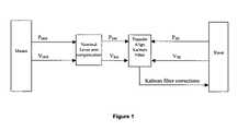
- FIG. 1shows a known MINS/SIMU system, in which a SIMU computes SIMU position (P SS ) and velocity (V SS ) information.
- a MINSprovides reference position (P SM ) and velocity (V SM ) to a Kalman filter, after correction/compensation for the nominal lever arm linkage between the MINS location and the SIMU location.
- the Kalman filterdetermines the differences between the SIMU position and velocity information, and the MINS reference position and velocity information, and provides corrections to SIMU position and velocity to improve SIMU's navigation accuracy.
- FIG. 1Ashows an alternative to the system of FIG. 1 , using the integral of MINS velocity, IV MM , instead of V MM .
- FIG. 1Bshows another alternative to the system of FIG. 1 , where the Kalman filter observes the difference of heading, in addition to the difference of position and velocity, computed by SIMU and MINS, and provides corrections to the SIMU.
- a transfer alignment mechanism/meanscomprises at least one MINS linked to at least one SIMU, where the MINS and SIMU are connected by a lever arm on the same vehicle, or on two different, linked vehicles such as the nose of an airplane and an antenna mounted elsewhere on the airplane.
- the MINSprovides, to one or more SIMUs in such vehicles, navigation information that includes position (P MM ), wander azimuth angle ( ⁇ ), velocity (V MM ), and body angular rate (W MM ).
- a SIMU's nominal position, called P SMis obtained by combining the nominal lever arm with P MM .
- the SIMUcomputes velocity (V SS ), direction cosines, meaning body coordinate frame-to-navigation coordinate frame transformation (direction cosines are needed to transfer accelerometer and gyro data from body frame to navigation frame), and body angular rate (W SS ), but does not compute SIMU position and wander angle. Instead, the SIMU uses position and wander angle from the MINS, as needed, in computing SIMU intermediate navigation parameters such as craft rate, earth rate, gravity, and earth radius of curvature. These intermediate parameters are needed for computing P, V, W, and ⁇ , in a standard navigation algorithm.
- a transfer alignment Kalman filterdetermines the difference between IV SS and IV SM , and the difference between IW SS and IW MM , expressed in the navigation coordinate frame, then provides updates to the SIMU.
- the components of integrals of velocity errors and body angular rate errors expressed in the navigation coordinate frameare modeled as six Kalman states, besides the standard navigation error states.
- Closed loop updatesare also applied to IV SS and IW SS .
- the Kalman filterprovides corrections to these parameters.
- the gyros and accelerometers of the SIMUtrack high frequency motions of the antenna.
- the Kalman filter updatesmaintain the long-term accuracy of velocity and attitude of the SIMU.
- Attitudeis the orientation of SIMU described by the transformation matrix T N BS .
- FIGS. 1 , 1 A and 1 Bshow block function diagrams of known transfer alignment means
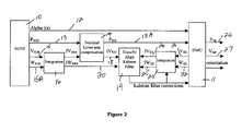
- FIG. 2shows a block function diagram of one embodiment of a new transfer alignment means
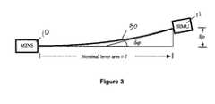
- FIG. 3shows, in schematic form, a lever arm connecting a MINS and a SIMU in an embodiment of a transfer alignment means.
- a MINS 10provides a SIMU 11 with MINS's wander angle 12 , denoted ⁇ , computed at the MINS.
- the MINSalso computes and passes P MM 13 to the nominal lever arm compensation block 14 .
- MINSpasses V MM 15 and W MM 15 A to a first integrator 16 .
- This first integrator 16computes and delivers IV MM 17 to the nominal lever arm compensation block 14 , which adjusts IV MM 17 and P MM 13 , then passes IV SM 18 , the integral of nominal velocity of SIMU and P SM 13 A to the Kalman filter 19 .
- IW MM 20also passes to the Kalman filter.
- the SIMUpasses V SS 21 and W SS 22 to another integrator 23 .
- Integrator 23passes IV SS 24 and IW SS 25 to Kalman filter 19 .
- Kalman filter 19compares IV SM 18 and IW MM 20 to IV SS 24 and IW SS 25 , computes corrections, and passes these corrections to integrator 23 and to SIMU 11 .
- the SIMU 11outputs P SB 26 , V SB 27 and an estimate of SIMU orientation 28 based in part on these corrections.
- FIG. 3shows that, if the characteristics of the vehicle between MINS 10 and SIMU 11 can be modeled, the SIMU 11 can output better position, velocity and orientation based on the difference in orientation (the bending angle of the lever arm 30 ) computed by the MINS and the SIMU 11 relative to the navigation coordinate frame.
- the displacement ( ⁇ p) of SIMU relative to MINScan be modeled as: ⁇ ( ⁇ l)/2 Eq (2.1)
- ⁇is the bending angle of the vehicle, and the bending angle is the attitude difference between the MINS and SIMU;
- V SBP SM + ⁇ Eq ⁇ ⁇ ( 2.4 )
Landscapes
- Engineering & Computer Science (AREA)
- Radar, Positioning & Navigation (AREA)
- Remote Sensing (AREA)
- Automation & Control Theory (AREA)
- Physics & Mathematics (AREA)
- General Physics & Mathematics (AREA)
- Navigation (AREA)
Abstract
Description
- MINS means Master Inertial Navigation System
- SIMU means Slave Inertial Measurement Unit
- α (alpha) means wander angle
- PMMis the position of MINS computed based on MINS data
- PSMis the nominal position of SIMU computed based on MINS data. “Nominal” means: without considering high frequency relative motion between MINS and SIMU.
- PSBis the best estimated position of SIMU, computed based on MINS and SIMU data
- VMMis the velocity of MINS computed based on MINS data
- IVMMis the integral of velocity of MINS computed based on MINS data
- IVSMis the integral of nominal velocity of SIMU computed based on MINS data
- IVSSis the integral of velocity of SIMU computed based on SIMU data
- VSSis the velocity of SIMU computed based on SIMU data
- VSBis the best estimated velocity of SIMU
- WMMis the body angular rate of the MINS computed based on MINS data expressed in the navigation coordinate frame
- WSSis the body angular rate of the SIMU computed based on SIMU data expressed in the navigation coordinate frame
- IWMMis the integral of body rate of MINS computed based on MINS data expressed in the navigation coordinate frame
- IWSSis the integral of body rate of SIMU computed based on SIMU data expressed in the navigation coordinate frame
- TNBmis the transformation matrix from MINS's body frame to navigation coordinate frame
- TBmVis the transformation matrix from vehicle frame to MINS's body coordinate frame
- HMis the vehicle heading computed by MINS
- TNBsis the transformation matrix from SIMU's body coordinate frame to navigation coordinate frame
- TBsVis the transformation matrix from vehicle frame to SIMU's body coordinate frame
- HSis the vehicle heading computed by SIMU
- Inertial Coordinate Frame—This is a system of three orthogonal axes that is fixed with respect to inertial space. The three axes have one axis directed along the mean rotational axis of the earth, a second axis defined in the mean equatorial plane of the earth and a third axis orthogonal to these two axes. The stars are fixed with respect to inertial space and so the Inertial Coordinate Frame is fixed with respect to the stars. One of the inertial frame axes in the mean equatorial plane of the earth can be selected to point relative to the stars. For example the direction of the star Aries is sometimes chosen.
- Earth-Fixed Coordinate Frame—This is a system of three orthogonal axes that rotates with respect to the Inertial Coordinate Frame at the rate of rotation of the earth. The earth has a mean rotation about its polar axis that is also one of the axes of the Inertial Coordinate Frame. The polar axis of the Earth-Fixed Coordinate Frame is coincident with the polar axis of the Inertial Coordinate Frame. A second axis of the Earth-Fixed Coordinate Frame lies in the mean equatorial plane of the earth in the direction of the longitudinal meridian that passes through Greenwich, England. The third axis is orthogonal to these two axes and thereby lies in the mean equatorial plane of the earth.
- Navigation Coordinate Frame—The navigation coordinate frame is a system of three orthogonal axes that is defined at the position of a navigation system. The Navigation Coordinate Frame has one axis coincident with what is called the “local vertical” that is defined as the direction of the gravity vector at the position of the navigation system. A second axis is defined in the “local level” plane that is orthogonal to the gravity vector. For example, this second axis can be chosen to point in the East direction. The third axis of the Navigation Coordinate Frame points in the North direction since it is orthogonal to the other two axes. The Navigation Coordinate Frame is translated in the East direction from the Earth-Fixed Coordinate Frame axis that resides in the mean equatorial plane of the earth in the Greenwich meridian by the longitude of the instantaneous position of the navigation system and translated in the North direction by the latitude of the instantaneous position of the navigation system.
- Body Coordinate Frame—The Body Coordinate Frame is a system of three orthogonal axes that is defined with respect to the vehicle that carries the navigation system. For example, for an airplane, one axis is normally pointed in the direction of the nose of the airplane, a second axis is pointed in the direction of the right wing and a third axis is pointed in the direction orthogonal to these other two axes.
- A navigation system may be installed on an aircraft such that axes of measurement of force by accelerometers, and angular change measured by gyros, are generally aligned with the body coordinate frame defined with respect to the vehicle. In these cases the orientation of the body coordinate frame with respect to the navigation coordinate frame can be defined by three angles of rotation. The first rotation can be about the local vertical of the navigation coordinate frame through an angle called heading of the vehicle. A second rotation can then be defined about the axis in the level plane displaced from the East direction. This second rotation angle is called pitch of the vehicle. A third rotation angle can be defined about the body frame axis pointed in the direction of the nose of the vehicle. This third rotation angle is called the roll of the vehicle.
- Inertial Sensor Reference Coordinate Frame—The inertial sensor reference coordinate frame is an orthogonal set of axes defined by the sensing axes of the gyros and accelerometers. In most cases an accelerometer and gyro pair are mounted so that their sensing axes are nominally coincident and directed along an axis of the inertial sensor reference frame. Consequently the sensing axes for three such pairs will be directed along one of the axes of the inertial sensor reference frame. For current strapdown inertial systems, the installation of the inertial system in the vehicle is such that the inertial sensor reference frame is nominally coincident with the body coordinate frame of the vehicle. This assumption applies to the description of the transfer alignment mechanization below.
- Alignment—Alignment is the process of determining the orientation of inertial instrument axes, gyros and accelerometers with respect to the Navigation Coordinate Frame. An example of this process comprises determining the orientation of a Body Coordinate Frame of a vehicle with respect to the East, North and vertical direction at the instantaneous position of a vehicle.
- Transfer Alignment—Transfer alignment is a term used in the inertial navigation system field to define the process where the orientation of the inertial instrument axes of one inertial navigation system that has not been aligned, is aligned, using information from a second inertial navigation system that is aligned with respect to the Navigation Coordinate Frame. When the Transfer Alignment process is complete, the unaligned inertial navigation system knows the orientation of its gyros and accelerometers with respect to the Navigation Coordinate Frame and can perform the navigation function.
IVSM=IVMM+(nominal lever arm at time,t1)−(nominal lever arm at time,t0) Eq (1.1)
PSB=PSM+(IVSS−IVSM) (Eq (1.2)
δρ≅(δφ×l)/2 Eq (2.1)
- l is the nominal lever arm vector, not including the relative motion of SIMU, in the navigation coordinate frame; and
- “x” is the vector cross product of δφ and l.
δφ=IWSS−IWMM Eq (2.2)
d(δφ)/dt=WSS−WMM Eq (2.3)
Claims (7)
Priority Applications (1)
| Application Number | Priority Date | Filing Date | Title |
|---|---|---|---|
| US10/892,577US7206694B2 (en) | 2004-07-16 | 2004-07-16 | Transfer alignment of navigation systems |
Applications Claiming Priority (1)
| Application Number | Priority Date | Filing Date | Title |
|---|---|---|---|
| US10/892,577US7206694B2 (en) | 2004-07-16 | 2004-07-16 | Transfer alignment of navigation systems |
Publications (2)
| Publication Number | Publication Date |
|---|---|
| US20060015248A1 US20060015248A1 (en) | 2006-01-19 |
| US7206694B2true US7206694B2 (en) | 2007-04-17 |
Family
ID=35600512
Family Applications (1)
| Application Number | Title | Priority Date | Filing Date |
|---|---|---|---|
| US10/892,577Expired - LifetimeUS7206694B2 (en) | 2004-07-16 | 2004-07-16 | Transfer alignment of navigation systems |
Country Status (1)
| Country | Link |
|---|---|
| US (1) | US7206694B2 (en) |
Cited By (5)
| Publication number | Priority date | Publication date | Assignee | Title |
|---|---|---|---|---|
| US20100286913A1 (en)* | 2007-11-23 | 2010-11-11 | Thales | System Including Two Combined Instruments and Method for Aligning Said System |
| US9020776B2 (en) | 2011-09-28 | 2015-04-28 | Caterpillar Inc. | Inclination angle compensation systems and methods |
| US9145144B2 (en) | 2011-09-28 | 2015-09-29 | Caterpillar Inc. | Inclination detection systems and methods |
| US9494430B2 (en) | 2014-10-27 | 2016-11-15 | Caterpillar Inc. | Positioning system implementing multi-sensor pose solution |
| CN107782304A (en)* | 2017-10-26 | 2018-03-09 | 广州视源电子科技股份有限公司 | Mobile robot positioning method and device, mobile robot and storage medium |
Families Citing this family (13)
| Publication number | Priority date | Publication date | Assignee | Title |
|---|---|---|---|---|
| EP1328775A1 (en)* | 2000-07-28 | 2003-07-23 | Litton Systems, Inc. | Attitude alignment of a slave inertial measurement system |
| US7979231B2 (en)* | 2008-11-13 | 2011-07-12 | Honeywell International Inc. | Method and system for estimation of inertial sensor errors in remote inertial measurement unit |
| US8566055B1 (en)* | 2010-02-12 | 2013-10-22 | Lockheed Martin Corporation | Gyro indexing compensation method and system |
| CA2769788C (en)* | 2011-03-23 | 2019-08-13 | Trusted Positioning Inc. | Methods of attitude and misalignment estimation for constraint free portable navigation |
| CN103148854A (en)* | 2013-01-28 | 2013-06-12 | 辽宁工程技术大学 | Attitude measurement method of micro-electro mechanical system (MEMS) inertial navigation system based on single-shaft forward revolution and reverse revolution |
| CN103884333B (en)* | 2014-03-31 | 2017-03-15 | 北京控制工程研究所 | A kind of survey of deep space independent navigation initial baseline catching method |
| CN103983280B (en)* | 2014-05-27 | 2017-02-15 | 上海新跃仪表厂 | Space-based inertial reference delivery method by use of speed difference information |
| CN108762324A (en)* | 2018-05-23 | 2018-11-06 | 深圳市道通智能航空技术有限公司 | Horizontal stage electric machine angle and angular speed evaluation method, device, holder and aircraft |
| CN109141476B (en)* | 2018-09-27 | 2019-11-08 | 东南大学 | A decoupling method of angular velocity during transfer alignment under dynamic deformation |
| CN110044384B (en)* | 2019-05-09 | 2020-10-30 | 北京壹氢科技有限公司 | Double-step filtering method suitable for vehicle-mounted transfer alignment |
| CN112229271B (en)* | 2020-09-23 | 2022-08-30 | 郑州天一飞控机电有限公司 | Helicopter-mounted missile transfer alignment delay time estimation method |
| CN114136340B (en)* | 2021-11-29 | 2023-06-16 | 重庆华渝电气集团有限公司 | Method for eliminating influence of misalignment angle error on initial alignment |
| CN116539030B (en)* | 2023-04-10 | 2025-08-19 | 中国人民解放军海军工程大学 | Navigation error fusion modulation method under configuration of two sets of single-axis rotation inertial navigation systems |
Citations (4)
| Publication number | Priority date | Publication date | Assignee | Title |
|---|---|---|---|---|
| US3056290A (en)* | 1959-12-31 | 1962-10-02 | Kearfott Company Inc | Multi-vehicular azimuth alignment computer |
| US5640325A (en)* | 1988-09-13 | 1997-06-17 | Litton Systems, Inc. | Sensor array dynamic position and orientation determination system |
| US6449559B2 (en)* | 1998-11-20 | 2002-09-10 | American Gnc Corporation | Fully-coupled positioning process and system thereof |
| US20040030464A1 (en)* | 2000-07-28 | 2004-02-12 | Buchler Robert J. | Attitude alignment of a slave inertial measurement system |
- 2004
- 2004-07-16USUS10/892,577patent/US7206694B2/ennot_activeExpired - Lifetime
Patent Citations (4)
| Publication number | Priority date | Publication date | Assignee | Title |
|---|---|---|---|---|
| US3056290A (en)* | 1959-12-31 | 1962-10-02 | Kearfott Company Inc | Multi-vehicular azimuth alignment computer |
| US5640325A (en)* | 1988-09-13 | 1997-06-17 | Litton Systems, Inc. | Sensor array dynamic position and orientation determination system |
| US6449559B2 (en)* | 1998-11-20 | 2002-09-10 | American Gnc Corporation | Fully-coupled positioning process and system thereof |
| US20040030464A1 (en)* | 2000-07-28 | 2004-02-12 | Buchler Robert J. | Attitude alignment of a slave inertial measurement system |
Cited By (5)
| Publication number | Priority date | Publication date | Assignee | Title |
|---|---|---|---|---|
| US20100286913A1 (en)* | 2007-11-23 | 2010-11-11 | Thales | System Including Two Combined Instruments and Method for Aligning Said System |
| US9020776B2 (en) | 2011-09-28 | 2015-04-28 | Caterpillar Inc. | Inclination angle compensation systems and methods |
| US9145144B2 (en) | 2011-09-28 | 2015-09-29 | Caterpillar Inc. | Inclination detection systems and methods |
| US9494430B2 (en) | 2014-10-27 | 2016-11-15 | Caterpillar Inc. | Positioning system implementing multi-sensor pose solution |
| CN107782304A (en)* | 2017-10-26 | 2018-03-09 | 广州视源电子科技股份有限公司 | Mobile robot positioning method and device, mobile robot and storage medium |
Also Published As
| Publication number | Publication date |
|---|---|
| US20060015248A1 (en) | 2006-01-19 |
Similar Documents
| Publication | Publication Date | Title |
|---|---|---|
| US7206694B2 (en) | Transfer alignment of navigation systems | |
| US20220404152A1 (en) | Motion constraint-aided underwater integrated navigation method employing improved sage-husa adaptive filtering | |
| US11105633B2 (en) | Navigation system utilizing yaw rate constraint during inertial dead reckoning | |
| US6459990B1 (en) | Self-contained positioning method and system thereof for water and land vehicles | |
| US9026263B2 (en) | Automotive navigation system and method to utilize internal geometry of sensor position with respect to rear wheel axis | |
| US6782742B1 (en) | Redundant system for the indication of heading and attitude in an aircraft | |
| EP1582840B1 (en) | Inertial navigation system error correction | |
| CN100529667C (en) | Star sensor attitude determination method at self-determination retrieve rail controlling fault | |
| CN111156994A (en) | INS/DR & GNSS loose integrated navigation method based on MEMS inertial component | |
| US20100019963A1 (en) | Vehicular navigation and positioning system | |
| CN110926468B (en) | Communication-in-motion antenna multi-platform navigation attitude determination method based on transfer alignment | |
| US11912433B2 (en) | Dual-filter-based transfer alignment method under dynamic deformation | |
| CN110285804B (en) | Vehicle collaborative navigation method based on relative motion model constraint | |
| EP2927640B1 (en) | Global positioning system (gps) self-calibrating lever arm function | |
| CN107289933A (en) | Double card Kalman Filtering guider and method based on MEMS sensor and VLC positioning fusions | |
| EP3786757B1 (en) | Camera stabilizer position correction method and device | |
| Gao et al. | GNSS/IMU/LiDAR fusion for vehicle localization in urban driving environments within a consensus framework | |
| CN109000640A (en) | Vehicle GNSS/INS Combinated navigation method based on discrete Grey Neural Network Model | |
| CN103913181A (en) | Airborne distribution type POS (position and orientation system) transfer alignment method based on parameter identification | |
| US12202531B2 (en) | Method for calculating an instantaneous velocity vector of a rail vehicle and corresponding system | |
| US20090171585A1 (en) | Computational scheme for MEMS inertial navigation systemes | |
| CN113074757B (en) | Calibration method for vehicle-mounted inertial navigation installation error angle | |
| CN105444762A (en) | Rapid inertial navigation error correction method for onboard satellite communication in motion | |
| CN110285834A (en) | Fast autonomous readjustment method of dual inertial navigation system based on one point position information | |
| Yang et al. | A SINS/CNS integrated navigation scheme with improved mathematical horizon reference |
Legal Events
| Date | Code | Title | Description |
|---|---|---|---|
| AS | Assignment | Owner name:NORTHROP GRUMMAN CORPORATION, CALIFORNIA Free format text:ASSIGNMENT OF ASSIGNORS INTEREST;ASSIGNORS:HUDDLE, JAMES R.;CHUEH, VICTOR K.;REEL/FRAME:015594/0031 Effective date:20040715 | |
| AS | Assignment | Owner name:LITTON SYSTEMS, INC., CALIFORNIA Free format text:ASSIGNMENT OF ASSIGNORS INTEREST;ASSIGNOR:NORTHROP GRUMMAN CORPORATION;REEL/FRAME:018148/0388 Effective date:20060621 | |
| STCF | Information on status: patent grant | Free format text:PATENTED CASE | |
| FEPP | Fee payment procedure | Free format text:PAYOR NUMBER ASSIGNED (ORIGINAL EVENT CODE: ASPN); ENTITY STATUS OF PATENT OWNER: LARGE ENTITY | |
| FPAY | Fee payment | Year of fee payment:4 | |
| AS | Assignment | Owner name:NORTHROP GRUMMAN SYSTEMS CORPORATION, CALIFORNIA Free format text:ASSIGNMENT OF ASSIGNORS INTEREST;ASSIGNOR:NORTHROP GRUMMAN CORPORATION;REEL/FRAME:025597/0505 Effective date:20110104 | |
| FPAY | Fee payment | Year of fee payment:8 | |
| MAFP | Maintenance fee payment | Free format text:PAYMENT OF MAINTENANCE FEE, 12TH YEAR, LARGE ENTITY (ORIGINAL EVENT CODE: M1553); ENTITY STATUS OF PATENT OWNER: LARGE ENTITY Year of fee payment:12 |