US7206554B1 - Transmit diversity with formed beams in a wireless communications system using a common pilot channel - Google Patents
Transmit diversity with formed beams in a wireless communications system using a common pilot channelDownload PDFInfo
- Publication number
- US7206554B1 US7206554B1US10/186,986US18698602AUS7206554B1US 7206554 B1US7206554 B1US 7206554B1US 18698602 AUS18698602 AUS 18698602AUS 7206554 B1US7206554 B1US 7206554B1
- Authority
- US
- United States
- Prior art keywords
- transmitting
- traffic
- signal
- remote terminal
- transmit
- Prior art date
- Legal status (The legal status is an assumption and is not a legal conclusion. Google has not performed a legal analysis and makes no representation as to the accuracy of the status listed.)
- Expired - Fee Related, expires
Links
Images


Classifications
- H—ELECTRICITY
- H04—ELECTRIC COMMUNICATION TECHNIQUE
- H04B—TRANSMISSION
- H04B7/00—Radio transmission systems, i.e. using radiation field
- H04B7/02—Diversity systems; Multi-antenna system, i.e. transmission or reception using multiple antennas
- H04B7/04—Diversity systems; Multi-antenna system, i.e. transmission or reception using multiple antennas using two or more spaced independent antennas
- H04B7/0408—Diversity systems; Multi-antenna system, i.e. transmission or reception using multiple antennas using two or more spaced independent antennas using two or more beams, i.e. beam diversity
- H—ELECTRICITY
- H04—ELECTRIC COMMUNICATION TECHNIQUE
- H04B—TRANSMISSION
- H04B7/00—Radio transmission systems, i.e. using radiation field
- H04B7/02—Diversity systems; Multi-antenna system, i.e. transmission or reception using multiple antennas
- H04B7/04—Diversity systems; Multi-antenna system, i.e. transmission or reception using multiple antennas using two or more spaced independent antennas
- H04B7/06—Diversity systems; Multi-antenna system, i.e. transmission or reception using multiple antennas using two or more spaced independent antennas at the transmitting station
- H04B7/0613—Diversity systems; Multi-antenna system, i.e. transmission or reception using multiple antennas using two or more spaced independent antennas at the transmitting station using simultaneous transmission
- H04B7/0615—Diversity systems; Multi-antenna system, i.e. transmission or reception using multiple antennas using two or more spaced independent antennas at the transmitting station using simultaneous transmission of weighted versions of same signal
- H04B7/0617—Diversity systems; Multi-antenna system, i.e. transmission or reception using multiple antennas using two or more spaced independent antennas at the transmitting station using simultaneous transmission of weighted versions of same signal for beam forming
- H—ELECTRICITY
- H04—ELECTRIC COMMUNICATION TECHNIQUE
- H04W—WIRELESS COMMUNICATION NETWORKS
- H04W16/00—Network planning, e.g. coverage or traffic planning tools; Network deployment, e.g. resource partitioning or cells structures
- H04W16/24—Cell structures
- H04W16/28—Cell structures using beam steering
Definitions
- the present inventionrelates generally to the field of digital radio signal communications. More particularly, the invention relates to using transmit diversity with user-specific transmission parameters together with a common pilot signal.
- pilot signalsthat the receiving terminal uses to demodulate received traffic, control, overhead or other signals.
- One such exampleis the pilot signal transmitted by a base station in a CDMA (code division multiple access) communications system.
- CDMAcode division multiple access
- a single common pilot signalis transmitted to all remote or subscriber terminals in the base station's coverage area.
- the coverage area of the base stationis typically referred to as a sector. Any signals transmitted to any particular user terminal can then be resolved with the help of the timing and phase information in the common pilot signal.
- the pilot signalis particularly effective when the signal propagation path for both the pilot and the user-specific signal is the same.
- the pilot signalis very effective.
- any difference between signalsmakes the pilot signal more difficult to use or, in other words, it makes the user-specific signal more difficult to demodulate. If, for example, the user-specific signal is spatially directed toward the remote terminal and the pilot signal is a common sector-wide signal, then the two signals can traverse a different signal propagation path. This will cause the two signals, as received by the remote terminal, to differ.
- the propagation channel of the pilot signal and the propagation channel of the traffic channelwill differ whenever they are transmitted with beams of different width and shape.
- the user terminaltypically uses the pilot signal to estimate a channel that then is used in the process of demodulating and detecting the symbols transmitted on the traffic channel.
- the difference in the propagation channel of the pilot signal and the traffic channeltherefore reduces the accuracy of the channel estimate.
- each usercan be provided with a user-specific pilot signal but this greatly increases the amount of traffic on the network.
- a method and apparatusare provided that allows beamforming to be used on a user-specific signal together with a sector-wide pilot signal in a communication system, such as a CDMA system.
- the inventionincludes transmitting a pilot signal with a wide beamwidth to a remote terminal from a first array, transmitting a first traffic signal with a narrow beamwidth directed to the remote terminal from the first array, and transmitting a second diversity traffic signal with a second narrow beamwidth directed to the remote terminal from a second array.
- the inventionmay also include transmitting a second pilot signal from the second antenna array.
- FIG. 1is a flow chart showing one embodiment of the present invention
- FIG. 2is a flow chart showing a process for optimizing transmission parameters for use in one embodiment of the present invention
- FIG. 3is a simplified block diagram of a base station on which an embodiment of the invention can be implemented.
- FIG. 4is a block diagram of a remote terminal on which an embodiment of the invention can be implemented.
- This inventionallows beamforming to be used on a user-specific signal together with a sector-wide pilot signal in a communication system, such as a CDMA system. Only one pilot signal is required in the sector, although two can be used if the transmit diversity scheme requires.
- beamformingis used on, for example, a traffic channel together with a sector-wide pilot, the difference in angular spread in the two propagation channels causes a mismatch in how the traffic channel and the pilot signal are received.
- the difficulties caused by this mismatchcan be alleviated by combining beamforming on the traffic channel with a sector wide pilot and a transmit diversity scheme.
- Adding transmit diversityadds a level of diversity into the channel mismatch. That is, the impairment due to the phase error (or other channel mismatch), is reduced by the fact that there are two different channels from the base station to the user terminal. The likelihood that both will have a large mismatch at the same time is less than the likelihood that any one of the channels will have a large mismatch.
- the robustness of the channelis significantly enhanced in a receiver that is designed to receive the particular type of diversity signals.
- the present inventionis described in the context of wireless base stations for air interfaces that allow beam forming, but it is not so limited. It is particularly applicable to wireless systems in which a pilot signal typically is shared among multiple users at the same time, as is commonly required in standards for CDMA (code division multiple access) systems. Current examples of such wireless systems are WCDMA (wideband CDMA), cdma2000, IS-95 (interim standard 95 of the Telecommunications Industry Association).
- WCDMAwideband CDMA
- cdma2000cdma2000
- IS-95interim standard 95 of the Telecommunications Industry Association
- the present inventionmay also be applied to some TDMA (time division multiple access) systems such as the downlink of HDR (high data rate for CDMA) and GSM (Global System for Mobile Communications).
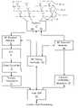
- FIG. 1shows a process flow diagram for optimizing transmit parameters in accordance with the present invention. This process is described in the context of a base station (BS), in a network that includes many base stations, sending a pilot signal to any subscriber stations or remote user terminals that may be within range of the base station.
- BSbase station
- the base stationmay be equipped with any of a variety of different antenna configurations.
- the base stationmay use two or more spatially separated antenna arrays 4 - 1 , 4 - 2 , 4 - 3 each with closely spaced antenna elements.
- the antenna elementscan be spaced on the order of one half the wavelength of a typical signal carrier wave, while the arrays are spaced apart by at least a distance of several carrier wavelengths.
- Antenna arrays with similar spacing between elementscan also be used with different polarization.
- two arrays of antennas differentiated either by their spatial location (e.g. 10–20 lambda or more apart) or by having different polarization (e.g. +45 and ⁇ 45 degree polarization respectively)can be applied.
- Other types of antenna arraysmay also be used.
- the BStransmits a pilot signal with a wide beamwidth 305 to any remote radios in range, for use as a phase reference to demodulate a traffic channel signal.
- the pilot channelcan be transmitted across an entire sector of the base station or any subsector.
- the pilot signalcan be transmitted on one or two sector-wide beams.
- the base stationalso transmits a first traffic signal with a narrow beamwidth 307 and transmits a second diversity traffic signal with a second narrow beamwidth 309 .
- the narrow beamwidthscan be selected using signal processing resources 31 , 33 of the base station specifically to provide diversity reception at a particular remote radio. Accordingly they are transmitted with different signal transmission parameters.
- the diversity signalsas mentioned above can be transmitted in accordance with any desired diversity scheme.
- the base stationwill also transmit a second pilot signal from the second antenna array 311 . These beams are typically all transmitted simultaneously, however, the particular timing of the transmissions will depend upon the particular diversity mode employed.
- the two user-specific narrow beamwidth signalsare transmitted using a transmit diversity scheme like the closed loop transmit diversity scheme in WCDMA.
- a transmit diversity schemelike the closed loop transmit diversity scheme in WCDMA.
- two slightly different pilot signalsare transmitted, one on a sector wide beam from the first array and one on a sector wide beam from the second array.
- the user terminalestimates the channel to each array and tells the base station how it should change the phase and possibly the amplitude of the traffic signals transmitted from each of the arrays so that the signals combine as coherently as possible. Since the traffic signal now arrives on two different beams with different channel mismatch, the user terminal benefits from this diversity in the channel mismatch, as mentioned above.
- the two user-specific narrow beamwidth signalsare transmitted using an open loop transmit diversity scheme like, for example, either of the space-time block coding schemes in cdma2000 or WCDMA.
- each part of the space-time block coding signalis transmitted over one of the beams.
- the user terminalthen combines the signal in its receiver according to the space-time block coding algorithm, as detailed in the respective standards.
- the useralso receives the signal on two different beams with different channel mismatch. Again providing a performance improvement due to diversity.
- the conventional receiver's tolerance to angular spreadis significantly increased. This occurs with closed loop and open loop transmit diversity schemes that follow the standards for which the receiver is designed. In other words, the same BER (bit error rate) can be achieved with a significantly larger angular spread than without using the diversity transmission mode. This effect is not due to multipath, fading or other problems which diversity transmission is typically deployed to solve.
- the performance increasecomes because the diversity transmission allows the receiver to overcome the phase mismatch between a directed traffic or other user-specific channel and a common pilot channel. As a result, the same channel quality can be obtained with all the benefits of directing narrow beams specifically to the intended user.
- the transmit parameterscan be optimized. This can be done in a variety of different ways well-known in the art. An alternative useful and novel approach is described below with respect to FIG. 2 . This process is described in the context of a base station (BS), in a network that includes many base stations, sending a BCH burst to any subscriber stations or remote user terminals that may be within range of the base station.
- BSbase station
- a BSor any radio operating in accordance with the present invention receives signals from a remote radio 105 , for example the subscriber terminal shown in FIG. 6 . Based on these received signals the BS can derive estimates of the channel on which the signals were received 107 . From the estimate of the receive channel, a model of the expected transmit channel can be derived 109 and from that a model of the transmit weights 111 that can be used to transmit a user-specific signal back to the remote radio over the model of the transmit channel. Alternatively, any other set of parameters can be used instead of weights depending on the design of the system. Some systems may use signatures, vectors, or other types of parameters to control the transmission of a signal by a set of antenna elements.
- the weights or other parametersare then optimized before use by a transmit power criterion 113 .
- Thiscan be done by developing a model of the expected transmit channel 115 and applying constraints on the estimated quality of the resulting transmitted signal 117 . There are a variety of different constraints as described below.
- the optimizationcan be used to maximize the received power of the remote terminal as compared to the transmitted power. Having optimized the transmission parameters, they can be used to transmit a communications signal to the remote terminal 119 .
- the signalcan be transmitted to the remote radio by applying a derived set of transmit weights to the elements of a transmit antenna array.
- the transmission parameterscan be optimized in one embodiment of the invention using an outer loop target SINR optimization.
- the downlink transmission weightsare selected based on estimates of the downlink performance of the selected weights.
- the estimatesare formed using models of the downlink channel derived from the uplink signals.
- the modelcan be an estimate of a downlink spatial covariance matrix formed from a corresponding uplink spatial covariance matrix.
- the performance of the downlink weightscan be estimated using the downlink channel model by estimating what outer loop SINR target would be required at the mobile in order to meet some specified outage requirement.
- the outage requirementcan be formulated in terms of how often the uncoded or coded BER or FER can be below some threshold.
- the outage requirementcan also be formulated as how often the mismatch in phase between the traffic channel and the sector wide pilot can be above a certain level.
- the downlink weights giving the lowest estimated outer loop SINR targetare then selected by solving an optimization problem, minimizing the outer loop SINR target.
- a base stationreceives signals on an uplink channel from a remote terminal and estimates receive spatial signatures.
- the receive spatial signaturecan either be used to estimate transmit spatial signatures or to estimate transmit spatial covariance matrix.
- Transmit spatial signatures and transmit spatial covariance matricescan be estimated in a variety of different ways well-known in the art.
- the transmit signatures or matricescan be a set of transmit signatures or matrices derived on a tap-by-tap basis.
- the transmit valuescan then be optimized using a model of the transmit or downlink channel.
- Different realizations of the transmit spatial signaturecan be generated by generating new random vectors v. If sets of signatures or matrices are used, this model can be applied to generate separate estimates of the transmit spatial signatures for different taps in a transmit spatio-temporal channel model.
- transmit weightscan be found that result in the lowest outer loop SINR target such that an outage requirement is met.
- outage requirementscan be used or outage requirements can be combined.
- One exampleis that the BER must be less than x percent at least y percent of the time.
- Another exampleis that the FER must be less than x percent at least y percent of the time.
- a third exampleis that the phase error of the user-specific signal compared to the phase of a pilot signal transmitted using a different weight must be less than x degrees at least y percent of the time. The selection of x and y will depend upon the particular configuration and requirements of a specific implementation.
- each weight vector in the family of weight vectorsis parameterized by one or more real numbers. For example, each weight generates a beam of a different beamwidth. Each weight vector generates a beam that has a constraint on the phase error of the generated beam as compared to the phase error of the beam of, for example a common pilot signal. The phase error constraint can also be a constraint on the maximum phase error as compared to the beam of the pilot signal for an range of angles of arrival. Each weight vector also maximizes a function of the gain over a range of angles of arrival.
- the particular parameters and constraints to be used in generating the predetermined family of weight vectorswill depend on the particular application.
- the parameterscan be optimized by selecting the downlink transmission weights as the weights that optimize the delivered power given a constraint on the phase error, and on the total transmitted power.
- the delivered powercan be estimated using any of the downlink channel estimates described above.
- the constraint on the phase errorcan be a constraint on the RMS (root mean square) phase error, the x:th percentile of the phase error, where x is selected for a particular implementation, or some other some other convenient form.
- a constraint on the difference between the phasors of the pilot channel complex gain or channel and the traffic channel complex gain or channel, or some other convenient function of the two channelscan be used.
- a base stationderives transmit spatial signatures or transmit spatial covariance matrices as described above and a similar model of the downlink channel is derived.
- the optimization problem in the present embodimentis to find a transmit weight vector that results in the maximum average delivered power, given a fixed transmit power, such that an outage requirement is met.
- the outage requirementcan take many different forms. One such form is that the phase error of the user specific signal as compared to the phase of a pilot signal transmitted using a different weight must be less than x degrees at least y percent of the time.
- the transmit weight vectorcan be found by using constrained optimization algorithms.
- the solution of the optimization problemcan be simplified using a predetermined set of weight vectors from which to select.
- the set of transmit weightscan be parameterized by one or more real numbers in the same manner as described above.
- the present inventionis implemented in an SDMA (Spatial Division Multiple Access) radio data communications system.
- each terminalis associated with a set of spatial parameters that relate to the radio communications channel between, for example, the base station and a user terminal.
- the spatial parameterscomprise a spatial signature for each terminal.
- the RF energy from the base stationcan be more precisely directed at a single user terminal, reducing interference with and lowering the noise threshold for other user terminals.
- data received from several different user terminals at the same timecan be resolved at lower receive energy levels.
- the spatial signaturescan include such things as the spatial location of the transmitters, the directions-of-arrival (DOAs), times-of-arrival (TOAs) and the distance from the base station.
- DOAsdirections-of-arrival
- TOAstimes-of-arrival
- Estimates of parameters such as signal power levels, DOAs, and TOAscan be determined using known training sequences placed in digital data streams for the purpose of channel equalization in conjunction with sensor (antenna) array information. This information is then used to calculate appropriate weights for spatial demultiplexers, multiplexers, and combiners. Techniques well known in the art, can be used to exploit the properties of the training sequences in determining spatial parameters. Further details regarding the use of spatial division and SDMA systems are described, for example, in U.S. Pat. No. 5,828,658, issued Oct. 27, 1998 to Ottersten et al. and U.S. Pat. No. 5,642,353, issued Jun. 24, 1997 to Roy, III et al.
- SDMAtime division multiple access
- FDMAfrequency division multiple access
- CDMAcode division multiple access
- FDDfrequency division duplexing
- TDDtime division duplexing
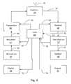
- FIG. 2shows an example of a base station of a wireless communications system or network suitable for implementing the present invention.
- the base stationuses SDMA technology which can be combined with other multiple access systems, such as time division multiple access (TDMA), frequency division multiple access (FDMA) and code division multiple access (CDMA). Multiple access can be combined with frequency division duplexing (FDD) or time division duplexing (TDD).
- the system or networkincludes a number of subscriber stations, also referred to as remote terminals or user terminals, such as that shown in FIG. 3 .
- the base stationmay be connected to a wide area network (WAN) through its host DSP 31 for providing any required data services and connections external to the immediate wireless system.
- WANwide area network
- a plurality of antennas 3is used to form an antenna array 4 , for example four antennas, although other numbers of antennas may be selected.
- Each antennais an element of a four-element array 4 .
- a plurality of arraysare provided 4 - 1 , 4 - 2 , 4 - 3 .
- the antenna elementsmay have a spacing of from one-quarter to four wavelengths of a typical carrier frequency while the arrays may be separated by ten or twenty wavelengths. The best spacing for spatial diversity will depend upon the particular frequencies involved, the physical installation and other aspects of the system. In many applications, the spacing between antenna elements of each array can be less than two wavelengths of the received signal. The spacing between antenna arrays can be more than two wavelengths of the received signal.
- the spacing between elements in an arrayis selected to minimize grating lobes when transmissions from each element are coherently combined.
- the arraysare spaced apart so as to form a uniform array of elements. The distance between nearest elements in different arrays is the same as the spacing between elements within an array. As mentioned above, it is also possible for each array to have only a single element.
- a set of spatial multiplexing weights for each subscriber stationare applied to the respective modulated signals to produce spatially multiplexed signals to be transmitted by the bank of four antennas.
- the host DSP 31produces and maintains spatial signatures for each subscriber station for each conventional channel and calculates spatial multiplexing and demultiplexing weights using received signal measurements. In this manner, the signals from the current active subscriber stations, some of which may be active on the same conventional channel, are separated and interference and noise suppressed.
- an optimized multi-lobe antenna radiation pattern tailored to the current active subscriber station connections and interference situationis created.
- the channels usedmay be partitioned in any manner.
- the channels usedmay be partitioned as defined in the GSM (Global System for Mobile Communications) air interface, or any other time division air interface protocol, such as Digital Cellular, PCS (Personal Communication System), PHS (Personal Handyphone System) or WLL (Wireless Local Loop).
- GSMGlobal System for Mobile Communications
- PCSPersonal Computer System
- PHSPersonal Handyphone System
- WLLWireless Local Loop
- continuous analog or CDMA channelscan be used.
- the outputs of the antennasare connected to a duplexer switch 7 , which in a TDD embodiment, may be a time switch.
- a duplexer switch 7which in a TDD embodiment, may be a time switch.
- Two possible implementations of the duplexer switchare as a frequency duplexer in a frequency division duplex (FDD) system, and as a time switch in a time division duplex (TDD) system.
- the antenna outputsare connected via the duplexer switch to a receiver 5 , and are converted down in analog by RF receiver (“RX”) modules 5 from the carrier frequency to an FM intermediate frequency (“IF”).
- RXRF receiver
- IFFM intermediate frequency
- ADCsanalog to digital converters
- Final down-converting to basebandis carried out digitally.
- Digital filterscan be used to implement the down-converting and the digital filtering, the latter using finite impulse response (FIR) filtering techniques. This is shown as block 13 .
- the inventioncan be adapted to suit a wide variety
- GSMGlobal System for Mobile Communications
- DSPdigital signal processor
- ASICApplication Specific Integrated Circuit
- FPGAField Programmable Gate Array
- timeslot processors 17For TDMA signals, eight Motorola DSP56300 Family DSPs can be used as timeslot processors, one per receive timeslot.
- the timeslot processors 17monitor the received signal power and estimate the frequency offset and time alignment. They also determine smart antenna weights for each antenna element. These are used in the SDMA scheme to determine a signal from a particular remote user and to demodulate the determined signal.
- the channelsmay be separated using codes in an FPGA and then further processed separately perhaps using separate DSPs for different users. Instead of being timeslot processors the processors are channel processors.
- the output of the timeslot processors 17is demodulated burst data for each of the eight receive timeslots.
- This datais sent to the host DSP processor 31 whose main function is to control all elements of the system and interface with the higher level processing, which is the processing which deals with what signals are required for communications in all the different control and service communication channels defined in the system's communication protocol.
- the host DSP 31can be a Motorola DSP56300 Family DSP.
- timeslot processorssend the determined receive weights for each user terminal to the host DSP 31 .
- the host DSP 31maintains state and timing information, receives uplink burst data from the timeslot processors 17 , and programs the timeslot processors 17 . In addition it decrypts, descrambles, checks error correcting code, and deconstructs bursts of the uplink signals, then formats the uplink signals to be sent for higher level processing in other parts of the base station.
- DSP 31may include a memory element to store data, instructions, or hopping functions or sequences.
- the base stationmay have a separate memory element or have access to an auxiliary memory element.
- itformats service data and traffic data for further higher processing in the base station, receives downlink messages and traffic data from the other parts of the base station, processes the downlink bursts and formats and sends the downlink bursts to a transmit controller/modulator, shown as 37 .
- the host DSPalso manages programming of other components of the base station including the transmit controller/modulator 37 and the RF timing controller shown as 33 .
- the RF controller 33reads and transmits power monitoring and control values, controls the duplexer 7 and receives timing parameters and other settings for each burst from the host DSP 31 .
- the transmit controller/modulator 37receives transmit data from the host DSP 31 .
- the transmit controlleruses this data to produce analog IF outputs which are sent to the RF transmitter (TX) modules 39 .
- the received data bitsare converted into a complex modulated signal, up-converted to an IF frequency, sampled, multiplied by transmit weights obtained from host DSP 31 , and converted via digital to analog converters (“DACs”) which are part of transmit controller/modulator 37 to analog transmit waveforms.
- DACsdigital to analog converters
- the analog waveformsare sent to the transmit modules 39 .
- the transmit modules 39up-convert the signals to the transmission frequency and amplify the signals.
- the amplified transmission signal outputsare sent to antennas 3 via the duplexer/time switch 7 .
- the signalsmay also be spread and scrambled using appropriate codes.
- FIG. 3depicts an example component arrangement in a remote terminal that provides data or voice communication.
- the remote terminal's antenna 45is connected to a duplexer 46 to permit the antenna 45 to be used for both transmission and reception.
- the antennacan be omni-directional or directional. For optimal performance, the antenna can be made up of multiple elements and employ spatial processing as discussed above for the base station. In an alternate embodiment, separate receive and transmit antennas are used eliminating the need for the duplexer 46 . In another alternate embodiment, where time division duplexing is used, a transmit/receive (TR) switch can be used instead of a duplexer as is well known in the art.
- the duplexer output 47serves as input to a receiver 48 .
- the receiver 48produces a down-converted signal 49 , which is the input to a demodulator 51 .
- a demodulated received sound or voice signal 67is input to a speaker 66 .
- the remote terminalhas a corresponding transmit chain in which data or voice to be transmitted is modulated in a modulator 57 .
- the modulated signal to be transmitted 59output by the modulator 57 , is up-converted and amplified by a transmitter 60 , producing a transmitter output signal 61 .
- the transmitter output 61is then input to the duplexer 46 for transmission by the antenna 45 .
- the demodulated received data 52is supplied to a remote terminal central processing unit 68 (CPU) as is received data before demodulation 50 .
- the remote terminal CPU 68can be implemented with a standard DSP (digital signal processor) device such as a Motorola series 56300 Family DSP. This DSP can also perform the functions of the demodulator 51 and the modulator 57 .
- the remote terminal CPU 68controls the receiver through line 63 , the transmitter through line 62 , the demodulator through line 52 and the modulator through line 58 . It also communicates with a keyboard 53 through line 54 and a display 56 through line 55 .
- a microphone 64 and speaker 66are connected through the modulator 57 and the demodulator 51 through lines 65 and 67 , respectively for a voice communications remote terminal.
- the microphone and speakerare also in direct communication with the CPU to provide voice or data communications.
- remote terminal CPU 68may also include a memory element to store data, instructions, and hopping functions or sequences. Alternatively, the remote terminal may have a separate memory element or have access to an auxiliary memory element.
- the speaker 66 , and the microphone 64are replaced or augmented by digital interfaces well-known in the art that allow data to be transmitted to and from an external data processing device (for example, a computer).
- the remote terminal's CPUis coupled to a standard digital interface such as a PCMCIA interface to an external computer and the display, keyboard, microphone and speaker are a part of the external computer.
- the remote terminal's CPU 68communicates with these components through the digital interface and the external computer's controller.
- the microphone and speakercan be deleted.
- the keyboard and displaycan be deleted.
- the present inventionincludes various steps.
- the steps of the present inventionmay be performed by hardware components, such as those shown in FIGS. 2 and 3 , or may be embodied in machine-executable instructions, which may be used to cause a general-purpose or special-purpose processor or logic circuits programmed with the instructions to perform the steps.
- the stepsmay be performed by a combination of hardware and software.
- the stepshave been described as being performed by either the base station or the user terminal. However, many of the steps described as being performed by the base station may be performed by the user terminal and vice versa.
- the inventionis equally applicable to systems in which terminals communicate with each other without either one being designated as a base station, a user terminal, a remote terminal or a subscriber station.
- the present inventionis equally applicable and useful in a peer-to-peer wireless network of communications devices using spatial processing.
- These devicesmay be cellular phones, PDA's, laptop computers, or any other wireless devices.
- these communications devices of wireless communications networksmay be generally referred to as radios.
- the base stationis described as performing spatial processing using adaptive antenna arrays.
- the user terminalscan also contain antenna arrays, and can also perform spatial processing both on receiving and transmitting (uplink and downlink) within the scope of the present invention.
- each base station antenna arraycould be a part of a different base station.
- the base station'scould share processing and transceiving functions.
- a central base station controllercould perform many of the functions described above and use the antenna arrays of one or more base stations to transmit and receive signals.
- the present inventionmay be provided as a computer program product, which may include a machine-readable medium having stored thereon instructions, which may be used to program a computer (or other electronic devices) to perform a process according to the present invention.
- the machine-readable mediummay include, but is not limited to, floppy diskettes, optical disks, CD-ROMs, and magneto-optical disks, ROMs, RAMs, EPROMs, EEPROMs, magnet or optical cards, flash memory, or other type of media/machine-readable medium suitable for storing electronic instructions.
- the present inventionmay also be downloaded as a computer program product, wherein the program may be transferred from a remote computer to a requesting computer by way of data signals embodied in a carrier wave or other propagation medium via a communication link (e.g., a modem or network connection).
- a communication linke.g., a modem or network connection
Landscapes
- Engineering & Computer Science (AREA)
- Computer Networks & Wireless Communication (AREA)
- Signal Processing (AREA)
- Mobile Radio Communication Systems (AREA)
Abstract
Description
Claims (39)
Priority Applications (2)
| Application Number | Priority Date | Filing Date | Title |
|---|---|---|---|
| US10/186,986US7206554B1 (en) | 2002-06-28 | 2002-06-28 | Transmit diversity with formed beams in a wireless communications system using a common pilot channel |
| US11/716,477US9160427B1 (en) | 2002-06-28 | 2007-03-09 | Transmit diversity with formed beams in a wireless communications system using a common pilot channel |
Applications Claiming Priority (1)
| Application Number | Priority Date | Filing Date | Title |
|---|---|---|---|
| US10/186,986US7206554B1 (en) | 2002-06-28 | 2002-06-28 | Transmit diversity with formed beams in a wireless communications system using a common pilot channel |
Related Child Applications (1)
| Application Number | Title | Priority Date | Filing Date |
|---|---|---|---|
| US11/716,477ContinuationUS9160427B1 (en) | 2002-06-28 | 2007-03-09 | Transmit diversity with formed beams in a wireless communications system using a common pilot channel |
Publications (1)
| Publication Number | Publication Date |
|---|---|
| US7206554B1true US7206554B1 (en) | 2007-04-17 |
Family
ID=37914188
Family Applications (2)
| Application Number | Title | Priority Date | Filing Date |
|---|---|---|---|
| US10/186,986Expired - Fee RelatedUS7206554B1 (en) | 2002-06-28 | 2002-06-28 | Transmit diversity with formed beams in a wireless communications system using a common pilot channel |
| US11/716,477Expired - Fee RelatedUS9160427B1 (en) | 2002-06-28 | 2007-03-09 | Transmit diversity with formed beams in a wireless communications system using a common pilot channel |
Family Applications After (1)
| Application Number | Title | Priority Date | Filing Date |
|---|---|---|---|
| US11/716,477Expired - Fee RelatedUS9160427B1 (en) | 2002-06-28 | 2007-03-09 | Transmit diversity with formed beams in a wireless communications system using a common pilot channel |
Country Status (1)
| Country | Link |
|---|---|
| US (2) | US7206554B1 (en) |
Cited By (20)
| Publication number | Priority date | Publication date | Assignee | Title |
|---|---|---|---|---|
| US20040252797A1 (en)* | 2003-06-13 | 2004-12-16 | Samsung Electronics Co., Ltd. | Method and apparatus for determining antenna weight in a closed-loop transmit diversity system |
| US20060007895A1 (en)* | 2001-06-06 | 2006-01-12 | Coralli Alessandro V | Method and apparatus for canceling pilot interference in a wireless communication system |
| US20060141934A1 (en)* | 2004-12-23 | 2006-06-29 | Pfister Henry D | Traffic interference cancellation |
| US20060141935A1 (en)* | 2004-12-23 | 2006-06-29 | Jilei Hou | Joint interference cancellation of pilot, overhead and traffic channels |
| US20060142041A1 (en)* | 2004-12-23 | 2006-06-29 | Stefano Tomasin | Adaptation of transmit subchannel gains in a system with interference cancellation |
| US20060234646A1 (en)* | 2005-03-07 | 2006-10-19 | Naguib Ayman F | Rate selection for a quasi-orthogonal communication system |
| US20060276229A1 (en)* | 2005-06-02 | 2006-12-07 | Alcatel | Method and device for providing static beamforming |
| US20070093261A1 (en)* | 2005-10-24 | 2007-04-26 | Jilei Hou | Iterative interference cancellation system and method |
| US20070111664A1 (en)* | 2001-06-06 | 2007-05-17 | Qualcomm Incorporated | Method and apparatus for canceling pilot interference in a wireless communication system |
| US20070147329A1 (en)* | 2005-12-06 | 2007-06-28 | Soriaga Joseph B | Method and system for signal reconstruction from spatially and temporally correlated received samples |
| US20100118843A1 (en)* | 2008-11-10 | 2010-05-13 | Qualcomm Incorporated | Communications methods and apparatus for use in communicating with access routers and/or other devices acting as communications peers |
| US20100234063A1 (en)* | 2009-03-13 | 2010-09-16 | Infineon Technologies Ag | Mobile radio communication devices and methods for controlling a mobile radio communication device |
| US20110188597A1 (en)* | 2000-06-13 | 2011-08-04 | Cpu Consultants, Inc. | Apparatus for generating at least one diverse signal based on at least one aspect of at least two received signals |
| US8422955B2 (en) | 2004-12-23 | 2013-04-16 | Qualcomm Incorporated | Channel estimation for interference cancellation |
| US20140072061A1 (en)* | 2005-04-21 | 2014-03-13 | Samsung Electronics Co., Ltd | System and method for channel estimation in a delay diversity wireless communication system |
| US20140269638A1 (en)* | 2005-12-20 | 2014-09-18 | Qualcomm Incorporated | Methods and systems for providing enhanced position location in wireless communications |
| WO2017157450A1 (en)* | 2016-03-17 | 2017-09-21 | Sony Mobile Communications Inc. | Operating a wireless communication system |
| WO2019126939A1 (en)* | 2017-12-25 | 2019-07-04 | 南通朗恒通信技术有限公司 | Method and device used in user equipment and base station for wireless communication |
| US11245485B2 (en)* | 2015-06-09 | 2022-02-08 | Panasonic Intellectual Property Corporation Of America | Transmitting method and transmitting apparatus for transmitting training signals and receiving a feedback signal |
| US11405877B2 (en)* | 2016-09-02 | 2022-08-02 | Sony Group Corporation | Downlink synchronization signals |
Families Citing this family (1)
| Publication number | Priority date | Publication date | Assignee | Title |
|---|---|---|---|---|
| WO2020061781A1 (en)* | 2018-09-25 | 2020-04-02 | 华为技术有限公司 | Communication method, apparatus and system |
Citations (11)
| Publication number | Priority date | Publication date | Assignee | Title |
|---|---|---|---|---|
| US6067290A (en)* | 1999-07-30 | 2000-05-23 | Gigabit Wireless, Inc. | Spatial multiplexing in a cellular network |
| WO2001063776A2 (en) | 2000-02-23 | 2001-08-30 | Metawave Communications Corporation | Transmitting beam forming in smart antenna array systems |
| US20010031647A1 (en)* | 1999-12-01 | 2001-10-18 | Scherzer Shimon B. | Adaptive antenna array wireless data access point |
| US6320853B1 (en) | 1999-09-27 | 2001-11-20 | Metawave Communications Corporation | Method of phase recovery in cellular communication systems |
| DE10026077A1 (en) | 2000-05-25 | 2001-12-06 | Siemens Ag | Beam shaping process |
| US6347234B1 (en)* | 1997-09-15 | 2002-02-12 | Adaptive Telecom, Inc. | Practical space-time radio method for CDMA communication capacity enhancement |
| US6738020B1 (en)* | 2001-07-31 | 2004-05-18 | Arraycomm, Inc. | Estimation of downlink transmission parameters in a radio communications system with an adaptive antenna array |
| US6782036B1 (en)* | 1999-05-26 | 2004-08-24 | Board Of Regents, The University Of Texas System | Smart antenna multiuser detector |
| US20040266457A1 (en)* | 1997-08-20 | 2004-12-30 | Dupray Dennis J. | Wireless location gateway and applications therefor |
| US6865377B1 (en)* | 2002-06-28 | 2005-03-08 | Arraycomm, Inc. | Combined open and closed loop beam forming in a multiple array radio communication system |
| US6999794B1 (en)* | 2002-06-28 | 2006-02-14 | Arraycomm Llc | Transmission of a common pilot channel from a beamforming transmit antenna array |
Family Cites Families (6)
| Publication number | Priority date | Publication date | Assignee | Title |
|---|---|---|---|---|
| US5781541A (en)* | 1995-05-03 | 1998-07-14 | Bell Atlantic Network Services, Inc. | CDMA system having time-distributed transmission paths for multipath reception |
| US20010033622A1 (en)* | 2000-03-14 | 2001-10-25 | Joengren George | Robust utilization of feedback information in space-time coding |
| US7248841B2 (en)* | 2000-06-13 | 2007-07-24 | Agee Brian G | Method and apparatus for optimization of wireless multipoint electromagnetic communication networks |
| US6847832B2 (en)* | 2001-03-09 | 2005-01-25 | Kathrein-Werke Kg | System and method for providing phase matching with optimized beam widths |
| US7227905B2 (en)* | 2001-09-18 | 2007-06-05 | Lucent Technologies Inc. | Open-loop diversity technique for systems employing multi-transmitter antennas |
| US20030162519A1 (en)* | 2002-02-26 | 2003-08-28 | Martin Smith | Radio communications device |
- 2002
- 2002-06-28USUS10/186,986patent/US7206554B1/ennot_activeExpired - Fee Related
- 2007
- 2007-03-09USUS11/716,477patent/US9160427B1/ennot_activeExpired - Fee Related
Patent Citations (11)
| Publication number | Priority date | Publication date | Assignee | Title |
|---|---|---|---|---|
| US20040266457A1 (en)* | 1997-08-20 | 2004-12-30 | Dupray Dennis J. | Wireless location gateway and applications therefor |
| US6347234B1 (en)* | 1997-09-15 | 2002-02-12 | Adaptive Telecom, Inc. | Practical space-time radio method for CDMA communication capacity enhancement |
| US6782036B1 (en)* | 1999-05-26 | 2004-08-24 | Board Of Regents, The University Of Texas System | Smart antenna multiuser detector |
| US6067290A (en)* | 1999-07-30 | 2000-05-23 | Gigabit Wireless, Inc. | Spatial multiplexing in a cellular network |
| US6320853B1 (en) | 1999-09-27 | 2001-11-20 | Metawave Communications Corporation | Method of phase recovery in cellular communication systems |
| US20010031647A1 (en)* | 1999-12-01 | 2001-10-18 | Scherzer Shimon B. | Adaptive antenna array wireless data access point |
| WO2001063776A2 (en) | 2000-02-23 | 2001-08-30 | Metawave Communications Corporation | Transmitting beam forming in smart antenna array systems |
| DE10026077A1 (en) | 2000-05-25 | 2001-12-06 | Siemens Ag | Beam shaping process |
| US6738020B1 (en)* | 2001-07-31 | 2004-05-18 | Arraycomm, Inc. | Estimation of downlink transmission parameters in a radio communications system with an adaptive antenna array |
| US6865377B1 (en)* | 2002-06-28 | 2005-03-08 | Arraycomm, Inc. | Combined open and closed loop beam forming in a multiple array radio communication system |
| US6999794B1 (en)* | 2002-06-28 | 2006-02-14 | Arraycomm Llc | Transmission of a common pilot channel from a beamforming transmit antenna array |
Non-Patent Citations (2)
| Title |
|---|
| Lindskog et al., "A Transmit Diversity Scheme for Channels with Intersymbol Interference", ICC 2000, Jun. 2000, vol. 1, pp. 307-311. |
| Pedersen et al, "A Simple Downlink Antenna Array Algorithm Based on a Hybrid Scheme of Transmit Diversity and Conventional Beamforming", 2001 IEEE, pp. 58-62. |
Cited By (62)
| Publication number | Priority date | Publication date | Assignee | Title |
|---|---|---|---|---|
| US9391745B2 (en) | 2000-06-13 | 2016-07-12 | Comcast Cable Communications, Llc | Multi-user transmissions |
| US9515788B2 (en) | 2000-06-13 | 2016-12-06 | Comcast Cable Communications, Llc | Originator and recipient based transmissions in wireless communications |
| US10349332B2 (en) | 2000-06-13 | 2019-07-09 | Comcast Cable Communications, Llc | Network communication using selected resources |
| US10257765B2 (en) | 2000-06-13 | 2019-04-09 | Comcast Cable Communications, Llc | Transmission of OFDM symbols |
| US9820209B1 (en) | 2000-06-13 | 2017-11-14 | Comcast Cable Communications, Llc | Data routing for OFDM transmissions |
| US9722842B2 (en) | 2000-06-13 | 2017-08-01 | Comcast Cable Communications, Llc | Transmission of data using a plurality of radio frequency channels |
| US9654323B2 (en) | 2000-06-13 | 2017-05-16 | Comcast Cable Communications, Llc | Data routing for OFDM transmission based on observed node capacities |
| US8451928B2 (en) | 2000-06-13 | 2013-05-28 | Aloft Media, Llc | Apparatus for calculating weights associated with a first signal and applying the weights to a second signal |
| US9401783B1 (en) | 2000-06-13 | 2016-07-26 | Comcast Cable Communications, Llc | Transmission of data to multiple nodes |
| US9356666B1 (en) | 2000-06-13 | 2016-05-31 | Comcast Cable Communications, Llc | Originator and recipient based transmissions in wireless communications |
| US9344233B2 (en) | 2000-06-13 | 2016-05-17 | Comcast Cable Communications, Llc | Originator and recipient based transmissions in wireless communications |
| US9209871B2 (en) | 2000-06-13 | 2015-12-08 | Comcast Cable Communications, Llc | Network communication using diversity |
| US9197297B2 (en) | 2000-06-13 | 2015-11-24 | Comcast Cable Communications, Llc | Network communication using diversity |
| USRE45807E1 (en) | 2000-06-13 | 2015-11-17 | Comcast Cable Communications, Llc | Apparatus for transmitting a signal including transmit data to a multiple-input capable node |
| USRE45775E1 (en) | 2000-06-13 | 2015-10-20 | Comcast Cable Communications, Llc | Method and system for robust, secure, and high-efficiency voice and packet transmission over ad-hoc, mesh, and MIMO communication networks |
| US9106286B2 (en) | 2000-06-13 | 2015-08-11 | Comcast Cable Communications, Llc | Network communication using diversity |
| US20110188597A1 (en)* | 2000-06-13 | 2011-08-04 | Cpu Consultants, Inc. | Apparatus for generating at least one diverse signal based on at least one aspect of at least two received signals |
| US20110194591A1 (en)* | 2000-06-13 | 2011-08-11 | Cpu Consultants, Inc. | Apparatus for transmitting a signal including transmit data to a multiple-input capable node |
| US8451929B2 (en) | 2000-06-13 | 2013-05-28 | Aloft Media, Llc | Apparatus for calculating weights associated with a received signal and applying the weights to transmit data |
| US8315326B2 (en) | 2000-06-13 | 2012-11-20 | Aloft Media, Llc | Apparatus for generating at least one signal based on at least one aspect of at least two received signals |
| US8315327B2 (en) | 2000-06-13 | 2012-11-20 | Aloft Media, Llc | Apparatus for transmitting a signal including transmit data to a multiple-input capable node |
| US20060007895A1 (en)* | 2001-06-06 | 2006-01-12 | Coralli Alessandro V | Method and apparatus for canceling pilot interference in a wireless communication system |
| US7903770B2 (en) | 2001-06-06 | 2011-03-08 | Qualcomm Incorporated | Method and apparatus for canceling pilot interference in a wireless communication system |
| US8611311B2 (en) | 2001-06-06 | 2013-12-17 | Qualcomm Incorporated | Method and apparatus for canceling pilot interference in a wireless communication system |
| US20110069736A1 (en)* | 2001-06-06 | 2011-03-24 | Qualcomm Incorporated | Method and apparatus for canceling pilot interference in a wireless communication system |
| US20070111664A1 (en)* | 2001-06-06 | 2007-05-17 | Qualcomm Incorporated | Method and apparatus for canceling pilot interference in a wireless communication system |
| US8644264B2 (en) | 2001-06-06 | 2014-02-04 | Qualcomm Incorporated | Method and apparatus for canceling pilot interference in a wireless communication system |
| US8363744B2 (en) | 2001-06-10 | 2013-01-29 | Aloft Media, Llc | Method and system for robust, secure, and high-efficiency voice and packet transmission over ad-hoc, mesh, and MIMO communication networks |
| US7391817B2 (en)* | 2003-06-13 | 2008-06-24 | Samsung Electronics Co., Ltd | Method and apparatus for determining antenna weight in a closed-loop transmit diversity system |
| US20040252797A1 (en)* | 2003-06-13 | 2004-12-16 | Samsung Electronics Co., Ltd. | Method and apparatus for determining antenna weight in a closed-loop transmit diversity system |
| US8406695B2 (en)* | 2004-12-23 | 2013-03-26 | Qualcomm Incorporated | Joint interference cancellation of pilot, overhead and traffic channels |
| US20060141935A1 (en)* | 2004-12-23 | 2006-06-29 | Jilei Hou | Joint interference cancellation of pilot, overhead and traffic channels |
| US20060142041A1 (en)* | 2004-12-23 | 2006-06-29 | Stefano Tomasin | Adaptation of transmit subchannel gains in a system with interference cancellation |
| US8099123B2 (en) | 2004-12-23 | 2012-01-17 | Qualcomm Incorporated | Adaptation of transmit subchannel gains in a system with interference cancellation |
| US8442441B2 (en) | 2004-12-23 | 2013-05-14 | Qualcomm Incorporated | Traffic interference cancellation |
| US8422955B2 (en) | 2004-12-23 | 2013-04-16 | Qualcomm Incorporated | Channel estimation for interference cancellation |
| US20060141934A1 (en)* | 2004-12-23 | 2006-06-29 | Pfister Henry D | Traffic interference cancellation |
| US20060234646A1 (en)* | 2005-03-07 | 2006-10-19 | Naguib Ayman F | Rate selection for a quasi-orthogonal communication system |
| US8422963B2 (en) | 2005-03-07 | 2013-04-16 | Qualcomm Incorporated | Rate selection for a quasi-orthogonal communication system |
| US7809336B2 (en)* | 2005-03-07 | 2010-10-05 | Qualcomm Incorporated | Rate selection for a quasi-orthogonal communication system |
| US9001774B2 (en)* | 2005-04-21 | 2015-04-07 | Samsung Electronics Co., Ltd. | System and method for channel estimation in a delay diversity wireless communication system |
| US20140072061A1 (en)* | 2005-04-21 | 2014-03-13 | Samsung Electronics Co., Ltd | System and method for channel estimation in a delay diversity wireless communication system |
| US20060276229A1 (en)* | 2005-06-02 | 2006-12-07 | Alcatel | Method and device for providing static beamforming |
| US8472877B2 (en) | 2005-10-24 | 2013-06-25 | Qualcomm Incorporated | Iterative interference cancellation system and method |
| US20070093261A1 (en)* | 2005-10-24 | 2007-04-26 | Jilei Hou | Iterative interference cancellation system and method |
| US20070147329A1 (en)* | 2005-12-06 | 2007-06-28 | Soriaga Joseph B | Method and system for signal reconstruction from spatially and temporally correlated received samples |
| US8385388B2 (en) | 2005-12-06 | 2013-02-26 | Qualcomm Incorporated | Method and system for signal reconstruction from spatially and temporally correlated received samples |
| US20140269638A1 (en)* | 2005-12-20 | 2014-09-18 | Qualcomm Incorporated | Methods and systems for providing enhanced position location in wireless communications |
| US10694517B2 (en) | 2005-12-20 | 2020-06-23 | Qualcomm Incorporated | Methods and systems for providing enhanced position location in wireless communications |
| US9955476B2 (en)* | 2005-12-20 | 2018-04-24 | Qualcomm Incorporated | Methods and systems for providing enhanced position location in wireless communications |
| US8160039B2 (en)* | 2008-11-10 | 2012-04-17 | Qualcomm Incorporated | Communications methods and apparatus for use in communicating with access routers and/or other devices acting as communications peers |
| US20100118843A1 (en)* | 2008-11-10 | 2010-05-13 | Qualcomm Incorporated | Communications methods and apparatus for use in communicating with access routers and/or other devices acting as communications peers |
| US9204370B2 (en) | 2009-03-13 | 2015-12-01 | Intel Mobile Communications GmbH | Mobile radio communication devices and methods for controlling a mobile radio communication device |
| US8135436B2 (en) | 2009-03-13 | 2012-03-13 | Intel Mobile Communications GmbH | Mobile radio communication devices and methods for controlling a mobile radio communication device |
| US20100234063A1 (en)* | 2009-03-13 | 2010-09-16 | Infineon Technologies Ag | Mobile radio communication devices and methods for controlling a mobile radio communication device |
| US11245485B2 (en)* | 2015-06-09 | 2022-02-08 | Panasonic Intellectual Property Corporation Of America | Transmitting method and transmitting apparatus for transmitting training signals and receiving a feedback signal |
| US10382117B2 (en) | 2016-03-17 | 2019-08-13 | Sony Mobile Communications Inc. | Operating a wireless communication system |
| WO2017157450A1 (en)* | 2016-03-17 | 2017-09-21 | Sony Mobile Communications Inc. | Operating a wireless communication system |
| US11405877B2 (en)* | 2016-09-02 | 2022-08-02 | Sony Group Corporation | Downlink synchronization signals |
| CN111108698A (en)* | 2017-12-25 | 2020-05-05 | 南通朗恒通信技术有限公司 | A kind of user equipment used for wireless communication, method and apparatus in base station |
| WO2019126939A1 (en)* | 2017-12-25 | 2019-07-04 | 南通朗恒通信技术有限公司 | Method and device used in user equipment and base station for wireless communication |
| CN111108698B (en)* | 2017-12-25 | 2021-08-27 | 南通朗恒通信技术有限公司 | User equipment, base station and method therein used for wireless communication |
Also Published As
| Publication number | Publication date |
|---|---|
| US9160427B1 (en) | 2015-10-13 |
Similar Documents
| Publication | Publication Date | Title |
|---|---|---|
| US9160427B1 (en) | Transmit diversity with formed beams in a wireless communications system using a common pilot channel | |
| US7342912B1 (en) | Selection of user-specific transmission parameters for optimization of transmit performance in wireless communications using a common pilot channel | |
| US7372911B1 (en) | Beam forming and transmit diversity in a multiple array radio communications system | |
| US6738020B1 (en) | Estimation of downlink transmission parameters in a radio communications system with an adaptive antenna array | |
| JP4451789B2 (en) | Use of beamforming and closed-loop transmit diversity in multi-beam antenna systems | |
| RU2285316C2 (en) | Device and method for shaping transfer beam of intelligent-antenna direct communication line in mobile communication system | |
| US6999794B1 (en) | Transmission of a common pilot channel from a beamforming transmit antenna array | |
| US5999826A (en) | Devices for transmitter path weights and methods therefor | |
| US7203519B2 (en) | Implementation method of pilot signal | |
| EP1685661B1 (en) | Method and apparatus for multi-beam antenna system | |
| US8891647B2 (en) | System and method for user specific antenna down tilt in wireless cellular networks | |
| US7221699B1 (en) | External correction of errors between traffic and training in a wireless communications system | |
| AU742496B2 (en) | Method and apparatus for directional radio communication | |
| US6865377B1 (en) | Combined open and closed loop beam forming in a multiple array radio communication system | |
| JPH08274687A (en) | CDMA wireless transmission device and CDMA wireless transmission system | |
| JP2004297750A (en) | Wireless communication system | |
| US7149547B2 (en) | Diversity transmission | |
| US7031679B2 (en) | Estimating power on spatial channels | |
| US7263082B1 (en) | Resolving user-specific narrow beam signals using a known sequence in a wireless communications system with a common pilot channel | |
| US7123943B2 (en) | Method of generating directional antenna beams, and radio transmitter | |
| US7088289B1 (en) | Antenna adaptation method, communication terminal, device; module and computer program product | |
| Lee et al. | A novel downlink beamforming scheme for FDD/SDMA systems | |
| HK1100794B (en) | Method and apparatus for multi-beam antenna system |
Legal Events
| Date | Code | Title | Description |
|---|---|---|---|
| AS | Assignment | Owner name:ARRAYCOMM, INC., CALIFORNIA Free format text:ASSIGNMENT OF ASSIGNORS INTEREST;ASSIGNOR:LINDSKOG, ERIK D.;REEL/FRAME:013338/0680 Effective date:20020828 | |
| AS | Assignment | Owner name:ARRAYCOMM LLC., CALIFORNIA Free format text:CHANGE OF NAME;ASSIGNOR:ARRAYCOMM, INC.;REEL/FRAME:017088/0957 Effective date:20051114 | |
| STCF | Information on status: patent grant | Free format text:PATENTED CASE | |
| AS | Assignment | Owner name:ARRAYCOMM LLC., CALIFORNIA Free format text:CORRECTIVE ASSIGNMENT TO CORRECT THE NATURE OF CONVEYANCE PREVIOUSLY RECORDED ON REEL 017088 FRAME 0957;ASSIGNOR:ARRAYCOMM, INC.;REEL/FRAME:021619/0597 Effective date:20051114 | |
| AS | Assignment | Owner name:INTEL CORPORATION, CALIFORNIA Free format text:ASSIGNMENT OF ASSIGNORS INTEREST;ASSIGNOR:ARRAYCOMM LLC;REEL/FRAME:021794/0107 Effective date:20081002 Owner name:INTEL CORPORATION,CALIFORNIA Free format text:ASSIGNMENT OF ASSIGNORS INTEREST;ASSIGNOR:ARRAYCOMM LLC;REEL/FRAME:021794/0107 Effective date:20081002 | |
| FPAY | Fee payment | Year of fee payment:4 | |
| FEPP | Fee payment procedure | Free format text:PAYOR NUMBER ASSIGNED (ORIGINAL EVENT CODE: ASPN); ENTITY STATUS OF PATENT OWNER: LARGE ENTITY Free format text:PAYER NUMBER DE-ASSIGNED (ORIGINAL EVENT CODE: RMPN); ENTITY STATUS OF PATENT OWNER: LARGE ENTITY | |
| FPAY | Fee payment | Year of fee payment:8 | |
| FEPP | Fee payment procedure | Free format text:MAINTENANCE FEE REMINDER MAILED (ORIGINAL EVENT CODE: REM.); ENTITY STATUS OF PATENT OWNER: LARGE ENTITY | |
| LAPS | Lapse for failure to pay maintenance fees | Free format text:PATENT EXPIRED FOR FAILURE TO PAY MAINTENANCE FEES (ORIGINAL EVENT CODE: EXP.); ENTITY STATUS OF PATENT OWNER: LARGE ENTITY | |
| STCH | Information on status: patent discontinuation | Free format text:PATENT EXPIRED DUE TO NONPAYMENT OF MAINTENANCE FEES UNDER 37 CFR 1.362 | |
| FP | Lapsed due to failure to pay maintenance fee | Effective date:20190417 |