US7204466B2 - Quick-acting telescopic tube - Google Patents
Quick-acting telescopic tubeDownload PDFInfo
- Publication number
- US7204466B2 US7204466B2US11/078,166US7816605AUS7204466B2US 7204466 B2US7204466 B2US 7204466B2US 7816605 AUS7816605 AUS 7816605AUS 7204466 B2US7204466 B2US 7204466B2
- Authority
- US
- United States
- Prior art keywords
- tube
- extension tube
- activating
- hole
- detent
- Prior art date
- Legal status (The legal status is an assumption and is not a legal conclusion. Google has not performed a legal analysis and makes no representation as to the accuracy of the status listed.)
- Expired - Fee Related, expires
Links
- 230000003213activating effectEffects0.000claimsabstractdescription52
Images


Classifications
- F—MECHANICAL ENGINEERING; LIGHTING; HEATING; WEAPONS; BLASTING
- F16—ENGINEERING ELEMENTS AND UNITS; GENERAL MEASURES FOR PRODUCING AND MAINTAINING EFFECTIVE FUNCTIONING OF MACHINES OR INSTALLATIONS; THERMAL INSULATION IN GENERAL
- F16B—DEVICES FOR FASTENING OR SECURING CONSTRUCTIONAL ELEMENTS OR MACHINE PARTS TOGETHER, e.g. NAILS, BOLTS, CIRCLIPS, CLAMPS, CLIPS OR WEDGES; JOINTS OR JOINTING
- F16B7/00—Connections of rods or tubes, e.g. of non-circular section, mutually, including resilient connections
- F16B7/10—Telescoping systems
- F16B7/105—Telescoping systems locking in discrete positions, e.g. in extreme extended position
- F—MECHANICAL ENGINEERING; LIGHTING; HEATING; WEAPONS; BLASTING
- F16—ENGINEERING ELEMENTS AND UNITS; GENERAL MEASURES FOR PRODUCING AND MAINTAINING EFFECTIVE FUNCTIONING OF MACHINES OR INSTALLATIONS; THERMAL INSULATION IN GENERAL
- F16M—FRAMES, CASINGS OR BEDS OF ENGINES, MACHINES OR APPARATUS, NOT SPECIFIC TO ENGINES, MACHINES OR APPARATUS PROVIDED FOR ELSEWHERE; STANDS; SUPPORTS
- F16M11/00—Stands or trestles as supports for apparatus or articles placed thereon ; Stands for scientific apparatus such as gravitational force meters
- F16M11/20—Undercarriages with or without wheels
- F16M11/24—Undercarriages with or without wheels changeable in height or length of legs, also for transport only, e.g. by means of tubes screwed into each other
- F16M11/242—Undercarriages with or without wheels changeable in height or length of legs, also for transport only, e.g. by means of tubes screwed into each other by spreading of the legs
- F—MECHANICAL ENGINEERING; LIGHTING; HEATING; WEAPONS; BLASTING
- F16—ENGINEERING ELEMENTS AND UNITS; GENERAL MEASURES FOR PRODUCING AND MAINTAINING EFFECTIVE FUNCTIONING OF MACHINES OR INSTALLATIONS; THERMAL INSULATION IN GENERAL
- F16M—FRAMES, CASINGS OR BEDS OF ENGINES, MACHINES OR APPARATUS, NOT SPECIFIC TO ENGINES, MACHINES OR APPARATUS PROVIDED FOR ELSEWHERE; STANDS; SUPPORTS
- F16M11/00—Stands or trestles as supports for apparatus or articles placed thereon ; Stands for scientific apparatus such as gravitational force meters
- F16M11/20—Undercarriages with or without wheels
- F16M11/24—Undercarriages with or without wheels changeable in height or length of legs, also for transport only, e.g. by means of tubes screwed into each other
- F16M11/26—Undercarriages with or without wheels changeable in height or length of legs, also for transport only, e.g. by means of tubes screwed into each other by telescoping, with or without folding
- F16M11/28—Undercarriages for supports with one single telescoping pillar
- F—MECHANICAL ENGINEERING; LIGHTING; HEATING; WEAPONS; BLASTING
- F16—ENGINEERING ELEMENTS AND UNITS; GENERAL MEASURES FOR PRODUCING AND MAINTAINING EFFECTIVE FUNCTIONING OF MACHINES OR INSTALLATIONS; THERMAL INSULATION IN GENERAL
- F16M—FRAMES, CASINGS OR BEDS OF ENGINES, MACHINES OR APPARATUS, NOT SPECIFIC TO ENGINES, MACHINES OR APPARATUS PROVIDED FOR ELSEWHERE; STANDS; SUPPORTS
- F16M2200/00—Details of stands or supports
- F16M2200/02—Locking means
- F16M2200/025—Locking means for translational movement
- F16M2200/027—Locking means for translational movement by friction
- F—MECHANICAL ENGINEERING; LIGHTING; HEATING; WEAPONS; BLASTING
- F16—ENGINEERING ELEMENTS AND UNITS; GENERAL MEASURES FOR PRODUCING AND MAINTAINING EFFECTIVE FUNCTIONING OF MACHINES OR INSTALLATIONS; THERMAL INSULATION IN GENERAL
- F16M—FRAMES, CASINGS OR BEDS OF ENGINES, MACHINES OR APPARATUS, NOT SPECIFIC TO ENGINES, MACHINES OR APPARATUS PROVIDED FOR ELSEWHERE; STANDS; SUPPORTS
- F16M2200/00—Details of stands or supports
- F16M2200/02—Locking means
- F16M2200/025—Locking means for translational movement
- F16M2200/028—Locking means for translational movement by positive interaction, e.g. male-female connections
- Y—GENERAL TAGGING OF NEW TECHNOLOGICAL DEVELOPMENTS; GENERAL TAGGING OF CROSS-SECTIONAL TECHNOLOGIES SPANNING OVER SEVERAL SECTIONS OF THE IPC; TECHNICAL SUBJECTS COVERED BY FORMER USPC CROSS-REFERENCE ART COLLECTIONS [XRACs] AND DIGESTS
- Y10—TECHNICAL SUBJECTS COVERED BY FORMER USPC
- Y10T—TECHNICAL SUBJECTS COVERED BY FORMER US CLASSIFICATION
- Y10T403/00—Joints and connections
- Y10T403/32—Articulated members
- Y10T403/32254—Lockable at fixed position
- Y10T403/32426—Plural distinct positions
Definitions
- the present inventionrelates to a telescopic tube, especially to a quick-acting telescopic tube that can support a musical instrument.
- a conventional telescopic tubecomprises a tube assembly ( 60 ), a lock activating assembly ( 70 ) and a locking assembly ( 80 ).
- the tube assembly ( 60 )comprises a stationary tube ( 61 ), a plug ( 62 ), a locking rod ( 63 ), an extension tube ( 64 ) and an activating tube ( 65 ).
- the stationary tube ( 61 )has a bottom.
- the plug ( 62 )is mounted in the bottom of the stationary tube ( 61 ).
- the locking rod ( 63 )is mounted in the stationary tube ( 61 ), is attached to the plug ( 62 ) and has multiple locking notches ( 631 ).
- the locking notches ( 631 )are formed separately in the locking rod ( 63 ).
- the extension tube ( 64 )is mounted slidably in the stationary tube ( 61 ) and has a top end, a bottom end, a through hole ( 641 ) and an elongated through hole.
- the through hole ( 641 )is formed transversely through the extension tube ( 64 ) near the top end.
- the elongated through holeis formed longitudinally near the bottom end.
- the activating tube ( 65 )is mounted slidably in the extension tube ( 64 ) around the locking rod ( 63 ) and has a top, a fastening hole ( 651 ), a mounting slot, a drive-pin hole and a drive pin ( 652 ).
- the fastening hole ( 651 )is formed transversely through the activating tube ( 65 ) near the top.
- the mounting slotis formed longitudinally through the activating rod ( 65 ), communicates with the top and has a bottom end.
- the drive-pin holeis formed transversely through the activating tube ( 65 ) near the bottom end of the mounting slot.
- the drive pin ( 652 )is mounted in the drive-pin hole.
- the lock activating assembly ( 70 )comprises a sleeve ( 71 ), a fastening pin ( 72 ), a spring ( 73 ) and a lever ( 74 ).
- the sleeve ( 71 )is mounted securely around the extension tube ( 64 ) and has a through hole and a bracket ( 711 ).
- the through holeis formed through the sleeve ( 71 ) and aligns with the through hole ( 641 ) in the extension tube ( 64 ).
- the bracket ( 711 )is formed on the sleeve ( 71 ).
- the fastening pin ( 72 )extends through the aligned through holes ( 641 ) in the extension tube ( 64 ) and the sleeve ( 71 ).
- the spring ( 73 )is attached to the fastening pin ( 72 ) and to the top of the activating tube ( 65 ).
- the lever ( 74 )is L-shaped, is mounted pivotally in the bracket ( 711 ) and has a longitudinal arm ( 741 ) and a transverse arm ( 742 ).
- the longitudinal arm ( 741 )pivots in the bracket ( 711 ).
- the transverse arm ( 742 )connects to the longitudinal arm ( 741 ), extends into the mounting slot in the activating tube ( 65 ) and has an elongated drive-pin hole ( 743 ) formed through the transverse arm ( 742 ).
- the drive pin ( 652 )is mounted through the drive-pin hole in the activating tube ( 65 ) and the elongated drive-pin hole ( 743 ) in the transverse arm ( 742 ).
- the locking assembly ( 80 )comprises a locking sleeve ( 81 ) and a clamp ( 82 ).
- the locking sleeve ( 81 )is mounted around the extension tube ( 64 ), connected to the activating tube ( 65 ) and has a pin ( 811 ), a bottom hole and a conical interior surface ( 812 ).
- the pin ( 811 )is mounted through the locking sleeve ( 81 ), the elongated hole in the extension tube ( 64 ) and the activating tube ( 65 ) to slide the locking sleeve ( 81 ) on the extension tube ( 64 ) when the lever ( 74 ) on the lock activating assembly ( 70 ) is pressed or released.
- the conical interior surface ( 812 )is formed adjacent to the bottom hole.
- the clamp ( 82 )connects pivotally to the extension tube ( 64 ), engages the conical interior surface ( 812 ) when the lever ( 74 ) on the lock activating assembly ( 70 ) is released and has two wings ( 821 ), a spring ( 822 ) and two latch pins ( 823 ).
- the wings ( 821 )are semicylindrical and are attached pivotally to the bottom end of the extension tube ( 64 ).
- Each wing ( 821 )has a proximal end, a distal end and a tapered head. The proximal end is attached pivotally to the bottom end of the extension tube ( 64 ).
- the tapered headis formed at the distal end and has a transverse latch pin hole.
- the tapered headsare pressed toward each other when the lever ( 74 ) on the lock activating assembly ( 70 ) is released.
- the spring ( 822 )is mounted between the tapered heads of the two wings ( 821 ) and presses the tapered heads apart when the lever ( 74 ) on the lock activating assembly ( 70 ) is pressed and pushes the locking sleeve ( 81 ) down.
- the latch pins ( 823 )are mounted respectively in the latch pin holes in the heads of the wings ( 821 ) and selectively engage locking notches ( 631 ) on the locking rod ( 63 ) when the conical interior surface ( 812 ) on the locking sleeve ( 81 ) presses the wings ( 821 ) together.
- the conventional telescopic tubeis more expensive because the conventional telescopic tube comprises many components, and the components are complicated.
- the present inventionprovides a quick-acting telescopic tube with simple and fewer components to mitigate or obviate the aforementioned problems.
- the main objective of the present inventionis to provide a quick-acting telescopic tube that has fewer and simple components and can support a musical instrument.
- the quick-acting telescopic tubehas a stationary tube, a detent lining, an extension tube, a lock activating assembly, a bottom plug, an activating rod, a spring and a ball.
- the detent liningis mounted securely in the stationary tube and has multiple detents.
- the extension tubeis mounted movably in the detent lining and has a top and a bottom.
- the lock activating assemblyis mounted around the top of the extension tube and has a lever extending into the extension tube.
- the bottom plugis mounted securely in the bottom of the extension tube and has a transverse through hole.
- the activating rodis mounted in the extension tube, connects to the lever and has a locking piston with an annular recess.
- the springis mounted between the bottom plug and the locking piston.
- the ballis mounted in the transverse through hole and selectively in either a detent in the detent lining or the annular recess in the locking piston.
- FIG. 1is a perspective view of a quick-acting telescopic tube in accordance with the present invention with a microphone support;
- FIG. 2is a perspective view in partial section of the quick-acting telescopic tube in FIG. 1 when the extension tube is unlocked;
- FIG. 3is a side view in partial section of the quick-acting telescopic tube in FIG. 1 when the extension tube is locked;
- FIG. 4is an enlarged side view in partial section of the quick-acting telescopic tube in FIG. 1 when the extension tube is locked;
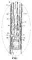
- FIG. 5is a side view in partial section of the quick-acting telescopic tube in FIG. 1 when the extension tube is unlocked;
- FIG. 6is a perspective view in partial section of a conventional telescopic tube in accordance with the prior art
- FIG. 7is an enlarged perspective view in partial section of a lock activating assembly in the conventional telescopic tube in FIG. 6 ;
- FIG. 8is an enlarged perspective view in partial section of a locking assembly in the conventional telescopic tube in FIG. 6 .
- a quick-acting telescopic tubein accordance with the present invention comprises a stationary tube ( 10 ), a detent lining ( 11 ), an extension tube ( 12 ), an lock activating assembly ( 13 ), a bottom plug ( 14 ), an activating rod ( 15 ), a spring ( 17 ) and a ball ( 18 ).
- the stationary tube ( 10 )has a top, a bottom and a bushing ( 100 ).
- the bushing ( 100 )is mounted in the top of the stationary tube ( 10 ) and has a through hole ( 101 ).
- the through hole ( 101 )is formed coaxially through the bushing ( 100 ).
- the detent lining ( 11 )is mounted securely in the stationary tube ( 10 ) and has a top, a sidewall and multiple detents ( 110 ).
- the detents ( 110 )are formed separately in the sidewall of the detent lining ( 11 ) and may be annular grooves, annular slots, through holes or the like.
- the extension tube ( 12 )is mounted movably in the detent lining ( 11 ) and the stationary tube ( 10 ), extends through the through hole ( 101 ) in the bushing ( 100 ) and has a top, a bottom, a sidewall and an activating hole ( 120 ).
- the activating hole ( 120 )is formed through the sidewall near the top of the extension tube ( 12 ).
- the lock activating assembly ( 13 )is mounted around the extension tube ( 12 ) and has a bracket ( 131 ) and a lever ( 132 ).
- the bracket ( 131 )is mounted around the extension tube ( 12 ) near the top of the extension tube ( 12 ) and has a through hole corresponding to the activating hole ( 120 ) in the extension tube ( 12 ).
- the lever ( 132 )is mounted pivotally in the bracket ( 131 ) and has a distal end that extends through the activating hole ( 120 ) into the extension tube ( 12 ).
- the bottom plug ( 14 )is hollow, is mounted securely in the bottom of the extension tube ( 12 ) and slidably in the detent lining ( 11 ) and has a top opening, an inner shoulder ( 141 ), a sidewall and a transverse through hole ( 140 ).
- the inner shoulder ( 141 )is formed in the bottom plug ( 14 ) near the top opening.
- the transverse through hole ( 140 )is formed in the sidewall of the bottom plug ( 14 ) and corresponds to the detents ( 110 ) in the detent lining ( 11 ).
- the activating rod ( 15 )is mounted movably in the extension tube ( 12 ), connects to the lever ( 132 ) and has a top, a bottom, a pivoting connector and a locking piston ( 16 ).
- the pivoting connectorconnects the top of the activating rod ( 15 ) to the lever ( 132 ) and may be a pivot block ( 150 ).
- the pivot block ( 150 )is attached to the top of the activating rod ( 15 ), is mounted movably in the extension tube ( 12 ), pivotally holds the distal end of the lever ( 132 ) and has a socket ( 151 ).
- the socket ( 151 )is formed in the pivot block ( 150 ), corresponds to the activating hole ( 120 ) in the extension tube ( 12 ) and holds the distal end of the lever ( 132 ). Pressing the lever ( 132 ) lifts the pivoting connector and the activating rod ( 15 ).
- the locking piston ( 16 )is attached to the bottom of the activating rod ( 15 ) and has an annular recess ( 160 ) and an optional inclined surface ( 161 ).
- the annular recess ( 160 )is formed in the locking piston ( 16 ).
- the inclined surface ( 161 )is formed in the locking piston ( 16 ) and connects to the annular recess ( 160 ).
- the spring ( 17 )is mounted around the activating rod ( 15 ) between the inner shoulder ( 141 ) in the bottom plug ( 14 ) and the locking piston ( 16 ).
- the ball ( 18 )is mounted movably in the transverse through hole ( 140 ) in the bottom plug ( 14 ) and selectively in either one of the detents ( 110 ) in the detent lining ( 11 ) or the annular recess ( 160 ) in the locking piston ( 16 ).
- the extension tube ( 12 )is locked relative to the stationary tube ( 10 ) when the locking piston ( 16 ) holds the ball ( 18 ) in one of the detents ( 110 ) in the detent lining ( 11 ).
- the extension tube ( 12 )is released from the stationary tube ( 10 ) by pressing the lever ( 132 ) in the lock activating assembly ( 13 ), which lifts the activating rod ( 15 ) and the locking piston ( 16 ) and aligns the annular recess ( 160 ) with the ball ( 18 ) in a detent ( 110 ) and the transverse through hole ( 140 ) in the bottom plug ( 14 ).
- Pushing or pulling the extension rod ( 12 )causes the ball ( 18 ) to detach from the detent ( 110 ) in the detent lining ( 11 ) and slide into the annular recess ( 160 ) in the locking piston ( 16 ). Then the extension tube ( 12 ) can be moved upward or downward.
- the advantage of the present inventionis that the quick-acting telescopic tube as described has fewer components, is simple and cost less.
Landscapes
- Engineering & Computer Science (AREA)
- General Engineering & Computer Science (AREA)
- Mechanical Engineering (AREA)
- Quick-Acting Or Multi-Walled Pipe Joints (AREA)
Abstract
Description
Claims (6)
Priority Applications (1)
| Application Number | Priority Date | Filing Date | Title |
|---|---|---|---|
| US11/078,166US7204466B2 (en) | 2005-03-11 | 2005-03-11 | Quick-acting telescopic tube |
Applications Claiming Priority (1)
| Application Number | Priority Date | Filing Date | Title |
|---|---|---|---|
| US11/078,166US7204466B2 (en) | 2005-03-11 | 2005-03-11 | Quick-acting telescopic tube |
Publications (2)
| Publication Number | Publication Date |
|---|---|
| US20060202098A1 US20060202098A1 (en) | 2006-09-14 |
| US7204466B2true US7204466B2 (en) | 2007-04-17 |
Family
ID=36969837
Family Applications (1)
| Application Number | Title | Priority Date | Filing Date |
|---|---|---|---|
| US11/078,166Expired - Fee RelatedUS7204466B2 (en) | 2005-03-11 | 2005-03-11 | Quick-acting telescopic tube |
Country Status (1)
| Country | Link |
|---|---|
| US (1) | US7204466B2 (en) |
Cited By (47)
| Publication number | Priority date | Publication date | Assignee | Title |
|---|---|---|---|---|
| US20060186286A1 (en)* | 2003-01-30 | 2006-08-24 | Paolo Speggiorin | Foot for optical or photographic supports |
| US20080078734A1 (en)* | 2004-07-01 | 2008-04-03 | Kuk-Won Yoon | Apparatus for Regulating Height of Music Rack |
| US20100243828A1 (en)* | 2009-03-27 | 2010-09-30 | Koenig & Meyer Gmbh & Co. Kg | Stand column, in particular music stand column or microphone stand column |
| US20110173867A1 (en)* | 2010-01-15 | 2011-07-21 | Desert Manufacturing, Llc | Adjustable support for firearms |
| US20120006949A1 (en)* | 2010-07-02 | 2012-01-12 | Andrew Laird | Positive lock adjustable seat post |
| US20120018251A1 (en)* | 2009-02-11 | 2012-01-26 | Smart Level Company B.V. | Supporting element for an object and apparatus comprising a supporting element |
| US20130175419A1 (en)* | 2012-01-06 | 2013-07-11 | Marathonnorco Aerospace, Inc. | Internal locking mechanism for a hold open rod |
| US8702046B2 (en) | 2010-07-26 | 2014-04-22 | L&P Property Management Company | Mounting device |
| US20160129974A1 (en)* | 2014-11-07 | 2016-05-12 | Dowco, Inc. | Articulated top |
| US9422018B2 (en) | 2008-11-25 | 2016-08-23 | Fox Factory, Inc. | Seat post |
| US9523406B2 (en) | 2009-03-19 | 2016-12-20 | Fox Factory, Inc. | Methods and apparatus for suspension adjustment |
| US9682604B2 (en) | 2009-03-19 | 2017-06-20 | Fox Factory, Inc. | Methods and apparatus for selective spring pre-load adjustment |
| US9783267B1 (en) | 2017-02-16 | 2017-10-10 | Dowco, Inc. | Cover system |
| US9783266B2 (en) | 2014-11-07 | 2017-10-10 | Dowco, Inc. | Articulated top |
| US9903528B1 (en)* | 2014-09-22 | 2018-02-27 | Joshua Terry Hatch | Telescoping lock mechanism |
| US10029172B2 (en) | 2008-11-25 | 2018-07-24 | Fox Factory, Inc. | Methods and apparatus for virtual competition |
| US10086670B2 (en) | 2009-03-19 | 2018-10-02 | Fox Factory, Inc. | Methods and apparatus for suspension set up |
| US10336148B2 (en) | 2009-01-07 | 2019-07-02 | Fox Factory, Inc. | Method and apparatus for an adjustable damper |
| US20190200754A1 (en)* | 2017-12-28 | 2019-07-04 | Velbon Kabushiki Kaisha | Support device |
| US10358180B2 (en) | 2017-01-05 | 2019-07-23 | Sram, Llc | Adjustable seatpost |
| US10550909B2 (en) | 2008-08-25 | 2020-02-04 | Fox Factory, Inc. | Methods and apparatus for suspension lock out and signal generation |
| US10670106B2 (en) | 2009-01-07 | 2020-06-02 | Fox Factory, Inc. | Method and apparatus for an adjustable damper |
| US10677309B2 (en) | 2011-05-31 | 2020-06-09 | Fox Factory, Inc. | Methods and apparatus for position sensitive suspension damping |
| US10723409B2 (en) | 2009-01-07 | 2020-07-28 | Fox Factory, Inc. | Method and apparatus for an adjustable damper |
| US10781879B2 (en) | 2009-01-07 | 2020-09-22 | Fox Factory, Inc. | Bypass for a suspension damper |
| US10793049B2 (en) | 2014-01-29 | 2020-10-06 | Dowco, Inc. | Resilient cover clip |
| US10821795B2 (en) | 2009-01-07 | 2020-11-03 | Fox Factory, Inc. | Method and apparatus for an adjustable damper |
| US10858071B1 (en) | 2019-10-09 | 2020-12-08 | Dowco, Inc. | Universal cover |
| US10859133B2 (en) | 2012-05-10 | 2020-12-08 | Fox Factory, Inc. | Method and apparatus for an adjustable damper |
| US10858072B1 (en) | 2019-06-27 | 2020-12-08 | Dowco, Inc. | Articulated top assist mechanism |
| US10864965B2 (en) | 2014-01-29 | 2020-12-15 | Dowco, Inc. | Tension held cover |
| US11046394B1 (en) | 2020-05-04 | 2021-06-29 | Dowco, Inc. | Reinforced articulated top |
| US11168758B2 (en) | 2009-01-07 | 2021-11-09 | Fox Factory, Inc. | Method and apparatus for an adjustable damper |
| US11279199B2 (en) | 2012-01-25 | 2022-03-22 | Fox Factory, Inc. | Suspension damper with by-pass valves |
| US11279198B2 (en) | 2009-10-13 | 2022-03-22 | Fox Factory, Inc. | Methods and apparatus for controlling a fluid damper |
| US11299233B2 (en) | 2009-01-07 | 2022-04-12 | Fox Factory, Inc. | Method and apparatus for an adjustable damper |
| US11306798B2 (en) | 2008-05-09 | 2022-04-19 | Fox Factory, Inc. | Position sensitive suspension damping with an active valve |
| US11472252B2 (en) | 2016-04-08 | 2022-10-18 | Fox Factory, Inc. | Electronic compression and rebound control |
| US11472512B1 (en) | 2021-05-17 | 2022-10-18 | Dowco, Inc. | Reinforced articulated top |
| US11499601B2 (en) | 2009-01-07 | 2022-11-15 | Fox Factory, Inc. | Remotely operated bypass for a suspension damper |
| US11519477B2 (en) | 2009-01-07 | 2022-12-06 | Fox Factory, Inc. | Compression isolator for a suspension damper |
| US11619278B2 (en) | 2009-03-19 | 2023-04-04 | Fox Factory, Inc. | Methods and apparatus for suspension adjustment |
| US20230184372A1 (en)* | 2021-12-15 | 2023-06-15 | Bushnell Holdings, Inc. | Telescoping support stand apparatus |
| US11708878B2 (en) | 2010-01-20 | 2023-07-25 | Fox Factory, Inc. | Remotely operated bypass for a suspension damper |
| US11807341B2 (en) | 2020-05-04 | 2023-11-07 | Dowco, Inc. | Reinforced articulated top |
| US11859690B2 (en) | 2009-10-13 | 2024-01-02 | Fox Factory, Inc. | Suspension system |
| US12122205B2 (en) | 2009-01-07 | 2024-10-22 | Fox Factory, Inc. | Active valve for an internal bypass |
Families Citing this family (7)
| Publication number | Priority date | Publication date | Assignee | Title |
|---|---|---|---|---|
| US20130193281A1 (en)* | 2012-01-12 | 2013-08-01 | The Music People, Inc. | Releasable locking connector |
| US8894025B2 (en)* | 2012-08-30 | 2014-11-25 | Tien Hsin Industries Co., Ltd. | Multi-position adjustable height seat post |
| CA2959649C (en)* | 2014-08-26 | 2023-09-26 | Nine Point Eight Inc. | Systems and methods for supporting telescoping elements |
| US9854913B1 (en)* | 2017-05-11 | 2018-01-02 | Ann Yang Inc. | Telescopic leg unit for table and chair |
| DE102017118417A1 (en)* | 2017-08-11 | 2019-02-14 | Dt Swiss Ag | bicycle component |
| CN113236945B (en)* | 2021-04-19 | 2022-10-25 | 三门峡职业技术学院 | Water conservancy and hydropower engineering surveying and mapping device |
| USD966766S1 (en)* | 2022-04-25 | 2022-10-18 | Lili Wang | Chair base |
Citations (15)
| Publication number | Priority date | Publication date | Assignee | Title |
|---|---|---|---|---|
| US2658777A (en)* | 1949-05-05 | 1953-11-10 | Rauglas Gerard | Locking device |
| US3604734A (en)* | 1969-05-13 | 1971-09-14 | Re Ly On Metal Products Inc | Adjusting and locking mechanism for adjustable and collapsible table |
| US4033543A (en)* | 1975-04-11 | 1977-07-05 | Anonima Castelli S.P.A. | Device for adjusting the height of the seat of arm-chairs and the like |
| US4318526A (en)* | 1978-09-13 | 1982-03-09 | Werner Per G | Adjustable telescopic device |
| US4526334A (en)* | 1981-09-28 | 1985-07-02 | Martela Oy | Device for adjusting the height of desktop, chair or similar |
| US4693442A (en)* | 1985-01-09 | 1987-09-15 | Dmi Fabrications Limited | Variable length columns |
| US4744690A (en)* | 1987-09-18 | 1988-05-17 | Hsieh Wu H | Stabilizer for telescopic stands |
| US4860987A (en)* | 1984-06-18 | 1989-08-29 | Mec-Lift A.S. | Adjustable telescopic devices |
| US5078349A (en)* | 1990-04-16 | 1992-01-07 | Midmark Corporation | Locking mechanism for an IV pole |
| US5729865A (en)* | 1996-03-07 | 1998-03-24 | Bestt Rollr, Inc. | Lock for telescoping extension poles |
| US6412737B1 (en)* | 2001-04-09 | 2002-07-02 | Moridaira Musical Instruments | Support stand |
| US6546596B2 (en)* | 2001-01-08 | 2003-04-15 | Rick V. Grote | Extension pole for tools |
| US6609686B2 (en)* | 2002-01-18 | 2003-08-26 | Tam Srl | Adjustable support apparatus |
| US6698698B1 (en)* | 2002-12-24 | 2004-03-02 | Wu-Hong Hsieh | Telescopic tube |
| GB2397164A (en)* | 2002-12-24 | 2004-07-14 | K H S Musical Instr Co Ltd | Telescopic stand for musical device |
- 2005
- 2005-03-11USUS11/078,166patent/US7204466B2/ennot_activeExpired - Fee Related
Patent Citations (15)
| Publication number | Priority date | Publication date | Assignee | Title |
|---|---|---|---|---|
| US2658777A (en)* | 1949-05-05 | 1953-11-10 | Rauglas Gerard | Locking device |
| US3604734A (en)* | 1969-05-13 | 1971-09-14 | Re Ly On Metal Products Inc | Adjusting and locking mechanism for adjustable and collapsible table |
| US4033543A (en)* | 1975-04-11 | 1977-07-05 | Anonima Castelli S.P.A. | Device for adjusting the height of the seat of arm-chairs and the like |
| US4318526A (en)* | 1978-09-13 | 1982-03-09 | Werner Per G | Adjustable telescopic device |
| US4526334A (en)* | 1981-09-28 | 1985-07-02 | Martela Oy | Device for adjusting the height of desktop, chair or similar |
| US4860987A (en)* | 1984-06-18 | 1989-08-29 | Mec-Lift A.S. | Adjustable telescopic devices |
| US4693442A (en)* | 1985-01-09 | 1987-09-15 | Dmi Fabrications Limited | Variable length columns |
| US4744690A (en)* | 1987-09-18 | 1988-05-17 | Hsieh Wu H | Stabilizer for telescopic stands |
| US5078349A (en)* | 1990-04-16 | 1992-01-07 | Midmark Corporation | Locking mechanism for an IV pole |
| US5729865A (en)* | 1996-03-07 | 1998-03-24 | Bestt Rollr, Inc. | Lock for telescoping extension poles |
| US6546596B2 (en)* | 2001-01-08 | 2003-04-15 | Rick V. Grote | Extension pole for tools |
| US6412737B1 (en)* | 2001-04-09 | 2002-07-02 | Moridaira Musical Instruments | Support stand |
| US6609686B2 (en)* | 2002-01-18 | 2003-08-26 | Tam Srl | Adjustable support apparatus |
| US6698698B1 (en)* | 2002-12-24 | 2004-03-02 | Wu-Hong Hsieh | Telescopic tube |
| GB2397164A (en)* | 2002-12-24 | 2004-07-14 | K H S Musical Instr Co Ltd | Telescopic stand for musical device |
Cited By (114)
| Publication number | Priority date | Publication date | Assignee | Title |
|---|---|---|---|---|
| US7506846B2 (en)* | 2003-01-30 | 2009-03-24 | Lino Manfrotto + Co. S.P.A. | Foot for optical or photographic supports |
| US20060186286A1 (en)* | 2003-01-30 | 2006-08-24 | Paolo Speggiorin | Foot for optical or photographic supports |
| US20080078734A1 (en)* | 2004-07-01 | 2008-04-03 | Kuk-Won Yoon | Apparatus for Regulating Height of Music Rack |
| US7552900B2 (en)* | 2004-07-01 | 2009-06-30 | Kuk-Won Yoon | Apparatus for regulating height of music rack |
| US11306798B2 (en) | 2008-05-09 | 2022-04-19 | Fox Factory, Inc. | Position sensitive suspension damping with an active valve |
| US10550909B2 (en) | 2008-08-25 | 2020-02-04 | Fox Factory, Inc. | Methods and apparatus for suspension lock out and signal generation |
| US11162555B2 (en) | 2008-08-25 | 2021-11-02 | Fox Factory, Inc. | Methods and apparatus for suspension lock out and signal generation |
| US12033739B2 (en) | 2008-11-25 | 2024-07-09 | Fox Factory, Inc. | Methods and apparatus for virtual competition |
| US11875887B2 (en) | 2008-11-25 | 2024-01-16 | Fox Factory, Inc. | Methods and apparatus for virtual competition |
| US11869651B2 (en) | 2008-11-25 | 2024-01-09 | Fox Factory, Inc. | Methods and apparatus for virtual competition |
| US11897571B2 (en) | 2008-11-25 | 2024-02-13 | Fox Factory, Inc. | Seat post |
| US11257582B2 (en) | 2008-11-25 | 2022-02-22 | Fox Factory, Inc. | Methods and apparatus for virtual competition |
| US11961602B2 (en) | 2008-11-25 | 2024-04-16 | Fox Factory, Inc. | Methods and apparatus for virtual competition |
| US9422018B2 (en) | 2008-11-25 | 2016-08-23 | Fox Factory, Inc. | Seat post |
| US11043294B2 (en) | 2008-11-25 | 2021-06-22 | Fox Factoory, Inc. | Methods and apparatus for virtual competition |
| US11021204B2 (en) | 2008-11-25 | 2021-06-01 | Fox Factory, Inc. | Seat post |
| US10029172B2 (en) | 2008-11-25 | 2018-07-24 | Fox Factory, Inc. | Methods and apparatus for virtual competition |
| US10537790B2 (en) | 2008-11-25 | 2020-01-21 | Fox Factory, Inc. | Methods and apparatus for virtual competition |
| US10472013B2 (en) | 2008-11-25 | 2019-11-12 | Fox Factory, Inc. | Seat post |
| US12170137B2 (en) | 2008-11-25 | 2024-12-17 | Fox Factory, Inc. | Methods and apparatus for virtual competition |
| US10336149B2 (en) | 2009-01-07 | 2019-07-02 | Fox Factory, Inc. | Method and apparatus for an adjustable damper |
| US10723409B2 (en) | 2009-01-07 | 2020-07-28 | Fox Factory, Inc. | Method and apparatus for an adjustable damper |
| US12377699B2 (en) | 2009-01-07 | 2025-08-05 | Fox Factory, Inc. | Method and apparatus for an adjustable damper |
| US12371122B2 (en) | 2009-01-07 | 2025-07-29 | Fox Factory, Inc. | Method and apparatus for an adjustable damper |
| US12257871B2 (en) | 2009-01-07 | 2025-03-25 | Fox Factory, Inc. | Method and apparatus for an adjustable damper |
| US11549565B2 (en) | 2009-01-07 | 2023-01-10 | Fox Factory, Inc. | Method and apparatus for an adjustable damper |
| US11660924B2 (en) | 2009-01-07 | 2023-05-30 | Fox Factory, Inc. | Method and apparatus for an adjustable damper |
| US11519477B2 (en) | 2009-01-07 | 2022-12-06 | Fox Factory, Inc. | Compression isolator for a suspension damper |
| US10336148B2 (en) | 2009-01-07 | 2019-07-02 | Fox Factory, Inc. | Method and apparatus for an adjustable damper |
| US11499601B2 (en) | 2009-01-07 | 2022-11-15 | Fox Factory, Inc. | Remotely operated bypass for a suspension damper |
| US11408482B2 (en) | 2009-01-07 | 2022-08-09 | Fox Factory, Inc. | Bypass for a suspension damper |
| US12134293B2 (en) | 2009-01-07 | 2024-11-05 | Fox Factory, Inc. | Method and apparatus for an adjustable damper |
| US12122205B2 (en) | 2009-01-07 | 2024-10-22 | Fox Factory, Inc. | Active valve for an internal bypass |
| US11794543B2 (en) | 2009-01-07 | 2023-10-24 | Fox Factory, Inc. | Method and apparatus for an adjustable damper |
| US11299233B2 (en) | 2009-01-07 | 2022-04-12 | Fox Factory, Inc. | Method and apparatus for an adjustable damper |
| US10821795B2 (en) | 2009-01-07 | 2020-11-03 | Fox Factory, Inc. | Method and apparatus for an adjustable damper |
| US11173765B2 (en) | 2009-01-07 | 2021-11-16 | Fox Factory, Inc. | Method and apparatus for an adjustable damper |
| US12091122B2 (en) | 2009-01-07 | 2024-09-17 | Fox Factory, Inc. | Method and apparatus for an adjustable damper |
| US11168758B2 (en) | 2009-01-07 | 2021-11-09 | Fox Factory, Inc. | Method and apparatus for an adjustable damper |
| US10670106B2 (en) | 2009-01-07 | 2020-06-02 | Fox Factory, Inc. | Method and apparatus for an adjustable damper |
| US11866120B2 (en) | 2009-01-07 | 2024-01-09 | Fox Factory, Inc. | Method and apparatus for an adjustable damper |
| US12044286B2 (en) | 2009-01-07 | 2024-07-23 | Fox Factory, Inc. | Compression isolator for a suspension damper |
| US11976706B2 (en) | 2009-01-07 | 2024-05-07 | Fox Factory, Inc. | Remotely operated bypass for a suspension damper |
| US11890908B2 (en) | 2009-01-07 | 2024-02-06 | Fox Factory, Inc. | Method and apparatus for an adjustable damper |
| US10781879B2 (en) | 2009-01-07 | 2020-09-22 | Fox Factory, Inc. | Bypass for a suspension damper |
| US10814689B2 (en) | 2009-01-07 | 2020-10-27 | Fox Factory, Inc. | Method and apparatus for an adjustable damper |
| US10800220B2 (en) | 2009-01-07 | 2020-10-13 | Fox Factory, Inc. | Method and apparatus for an adjustable damper |
| US10807433B2 (en) | 2009-01-07 | 2020-10-20 | Fox Factory, Inc. | Method and apparatus for an adjustable damper |
| US20120018251A1 (en)* | 2009-02-11 | 2012-01-26 | Smart Level Company B.V. | Supporting element for an object and apparatus comprising a supporting element |
| US9267519B2 (en)* | 2009-02-11 | 2016-02-23 | Smart Level Company B.V. | Supporting element for an object and apparatus comprising a supporting element |
| US12103349B2 (en) | 2009-03-19 | 2024-10-01 | Fox Factory, Inc. | Methods and apparatus for selective spring pre-load adjustment |
| US9682604B2 (en) | 2009-03-19 | 2017-06-20 | Fox Factory, Inc. | Methods and apparatus for selective spring pre-load adjustment |
| US11619278B2 (en) | 2009-03-19 | 2023-04-04 | Fox Factory, Inc. | Methods and apparatus for suspension adjustment |
| US11920655B2 (en) | 2009-03-19 | 2024-03-05 | Fox Factory, Inc. | Methods and apparatus for suspension adjustment |
| US10086670B2 (en) | 2009-03-19 | 2018-10-02 | Fox Factory, Inc. | Methods and apparatus for suspension set up |
| US10145435B2 (en) | 2009-03-19 | 2018-12-04 | Fox Factory, Inc. | Methods and apparatus for suspension adjustment |
| US9523406B2 (en) | 2009-03-19 | 2016-12-20 | Fox Factory, Inc. | Methods and apparatus for suspension adjustment |
| US11413924B2 (en) | 2009-03-19 | 2022-08-16 | Fox Factory, Inc. | Methods and apparatus for selective spring pre-load adjustment |
| US10591015B2 (en) | 2009-03-19 | 2020-03-17 | Fox Factory, Inc. | Methods and apparatus for suspension adjustment |
| US12163569B2 (en) | 2009-03-19 | 2024-12-10 | Fox Factory, Inc. | Methods and apparatus for suspension adjustment |
| US11655873B2 (en) | 2009-03-19 | 2023-05-23 | Fox Factory, Inc. | Methods and apparatus for suspension adjustment |
| US10414236B2 (en) | 2009-03-19 | 2019-09-17 | Fox Factory, Inc. | Methods and apparatus for selective spring pre-load adjustment |
| US20100243828A1 (en)* | 2009-03-27 | 2010-09-30 | Koenig & Meyer Gmbh & Co. Kg | Stand column, in particular music stand column or microphone stand column |
| US11279198B2 (en) | 2009-10-13 | 2022-03-22 | Fox Factory, Inc. | Methods and apparatus for controlling a fluid damper |
| US12005755B2 (en) | 2009-10-13 | 2024-06-11 | Fox Factory, Inc. | Methods and apparatus for controlling a fluid damper |
| US11859690B2 (en) | 2009-10-13 | 2024-01-02 | Fox Factory, Inc. | Suspension system |
| US20110173867A1 (en)* | 2010-01-15 | 2011-07-21 | Desert Manufacturing, Llc | Adjustable support for firearms |
| US11708878B2 (en) | 2010-01-20 | 2023-07-25 | Fox Factory, Inc. | Remotely operated bypass for a suspension damper |
| US8814109B2 (en)* | 2010-07-02 | 2014-08-26 | Fox Factory, Inc. | Positive lock adjustable seat post |
| US10843753B2 (en) | 2010-07-02 | 2020-11-24 | Fox Factory, Inc. | Lever assembly for positive lock adjustable seat post |
| US9650094B2 (en) | 2010-07-02 | 2017-05-16 | Fox Factory, Inc. | Lever assembly for positive lock adjustable seatpost |
| US20120006949A1 (en)* | 2010-07-02 | 2012-01-12 | Andrew Laird | Positive lock adjustable seat post |
| US10086892B2 (en) | 2010-07-02 | 2018-10-02 | Fox Factory, Inc. | Lever assembly for positive lock adjustable seat post |
| US11866110B2 (en) | 2010-07-02 | 2024-01-09 | Fox Factory, Inc. | Lever assembly for positive lock adjustable seat post |
| US8702046B2 (en) | 2010-07-26 | 2014-04-22 | L&P Property Management Company | Mounting device |
| US11796028B2 (en) | 2011-05-31 | 2023-10-24 | Fox Factory, Inc. | Methods and apparatus for position sensitive suspension damping |
| US10677309B2 (en) | 2011-05-31 | 2020-06-09 | Fox Factory, Inc. | Methods and apparatus for position sensitive suspension damping |
| US10759247B2 (en) | 2011-09-12 | 2020-09-01 | Fox Factory, Inc. | Methods and apparatus for suspension set up |
| US11958328B2 (en) | 2011-09-12 | 2024-04-16 | Fox Factory, Inc. | Methods and apparatus for suspension set up |
| US9599137B2 (en)* | 2012-01-06 | 2017-03-21 | MarathonNoroco Aerospace, Inc. | Internal locking mechanism for a hold open rod |
| US20130175419A1 (en)* | 2012-01-06 | 2013-07-11 | Marathonnorco Aerospace, Inc. | Internal locking mechanism for a hold open rod |
| US11279199B2 (en) | 2012-01-25 | 2022-03-22 | Fox Factory, Inc. | Suspension damper with by-pass valves |
| US11760150B2 (en) | 2012-01-25 | 2023-09-19 | Fox Factory, Inc. | Suspension damper with by-pass valves |
| US11629774B2 (en) | 2012-05-10 | 2023-04-18 | Fox Factory, Inc. | Method and apparatus for an adjustable damper |
| US12038062B2 (en) | 2012-05-10 | 2024-07-16 | Fox Factory, Inc. | Method and apparatus for an adjustable damper |
| US10859133B2 (en) | 2012-05-10 | 2020-12-08 | Fox Factory, Inc. | Method and apparatus for an adjustable damper |
| US10793049B2 (en) | 2014-01-29 | 2020-10-06 | Dowco, Inc. | Resilient cover clip |
| US10864965B2 (en) | 2014-01-29 | 2020-12-15 | Dowco, Inc. | Tension held cover |
| US11351909B2 (en) | 2014-01-29 | 2022-06-07 | Dowco, Inc. | Resilient cover clip |
| US10386011B2 (en)* | 2014-09-22 | 2019-08-20 | Joshua Terry Hatch | Telescoping lock mechanism |
| US11313509B2 (en) | 2014-09-22 | 2022-04-26 | Joshua Terry Hatch | Telescoping lock mechanism |
| US9903528B1 (en)* | 2014-09-22 | 2018-02-27 | Joshua Terry Hatch | Telescoping lock mechanism |
| US20190360634A1 (en)* | 2014-09-22 | 2019-11-28 | Joshua Terry Hatch | Telescoping lock mechanism |
| US9815525B2 (en) | 2014-11-07 | 2017-11-14 | Dowco, Inc. | Articulated top |
| US9849939B2 (en) | 2014-11-07 | 2017-12-26 | Dowco, Inc. | Articulated top |
| US9783266B2 (en) | 2014-11-07 | 2017-10-10 | Dowco, Inc. | Articulated top |
| US20160129974A1 (en)* | 2014-11-07 | 2016-05-12 | Dowco, Inc. | Articulated top |
| US9604702B2 (en)* | 2014-11-07 | 2017-03-28 | Dowco, Inc. | Articulated top |
| US11472252B2 (en) | 2016-04-08 | 2022-10-18 | Fox Factory, Inc. | Electronic compression and rebound control |
| US12162554B2 (en) | 2017-01-05 | 2024-12-10 | Sram, Llc | Adjustable seatpost |
| US10358180B2 (en) | 2017-01-05 | 2019-07-23 | Sram, Llc | Adjustable seatpost |
| US11738817B2 (en) | 2017-01-05 | 2023-08-29 | Sram, Llc | Adjustable seatpost |
| US9783267B1 (en) | 2017-02-16 | 2017-10-10 | Dowco, Inc. | Cover system |
| US10674814B2 (en)* | 2017-12-28 | 2020-06-09 | Velbon Kabushiki Kaisha | Support device |
| US20190200754A1 (en)* | 2017-12-28 | 2019-07-04 | Velbon Kabushiki Kaisha | Support device |
| US10858072B1 (en) | 2019-06-27 | 2020-12-08 | Dowco, Inc. | Articulated top assist mechanism |
| US10858071B1 (en) | 2019-10-09 | 2020-12-08 | Dowco, Inc. | Universal cover |
| US11702172B2 (en) | 2020-05-04 | 2023-07-18 | Dowco, Inc. | Reinforced articulated top |
| US11807341B2 (en) | 2020-05-04 | 2023-11-07 | Dowco, Inc. | Reinforced articulated top |
| US11046394B1 (en) | 2020-05-04 | 2021-06-29 | Dowco, Inc. | Reinforced articulated top |
| US11472512B1 (en) | 2021-05-17 | 2022-10-18 | Dowco, Inc. | Reinforced articulated top |
| US11518480B1 (en) | 2021-05-17 | 2022-12-06 | Dowco, Inc. | Reinforced articulated top |
| US20230184372A1 (en)* | 2021-12-15 | 2023-06-15 | Bushnell Holdings, Inc. | Telescoping support stand apparatus |
| US12196359B2 (en)* | 2021-12-15 | 2025-01-14 | Bushnell Holdings, Inc. | Telescoping support stand apparatus |
Also Published As
| Publication number | Publication date |
|---|---|
| US20060202098A1 (en) | 2006-09-14 |
Similar Documents
| Publication | Publication Date | Title |
|---|---|---|
| US7204466B2 (en) | Quick-acting telescopic tube | |
| US7721363B2 (en) | Slide rail | |
| US6698698B1 (en) | Telescopic tube | |
| US7628369B2 (en) | Telescopic tube | |
| US6550735B1 (en) | Sucker-type suspension structure | |
| US6227016B1 (en) | Cable lock assembly | |
| US8387222B2 (en) | Pen barrel assembling device | |
| US20060225981A1 (en) | Retractable handle of carry-on luggage | |
| US6820326B1 (en) | Compression assembly tool with multiple split bases | |
| US20080261790A1 (en) | Multi-stage orientating assembly for an inversion table | |
| US20070246945A1 (en) | Door-closing assembly | |
| US20060086869A1 (en) | Tripod for a musical instrument | |
| US20070170406A1 (en) | Coupling device for two connecting poles | |
| US20040237621A1 (en) | Contraction tool | |
| US20070131091A1 (en) | Support for a musical keyboard instrument | |
| US8020832B2 (en) | Anti-skid sleeve for musical instrument stand | |
| US20100269622A1 (en) | Theftproof Clutch Handle that is Detached Easily and Quickly | |
| CN102648491B (en) | Travel guitar with hinged neck | |
| US6973853B2 (en) | Infinitely variable angle adjusting device for a handlebar of a motorized vehicle | |
| US6958440B2 (en) | Adjust device for adjusting a tension of a snare of a snare drum | |
| US20100298783A1 (en) | Manual switch for a closed suction tube | |
| US9616317B2 (en) | Collapsible pole assembly | |
| US20070145202A1 (en) | Musical instrument telescopic supporting bar with an adjusting device | |
| CN109989985B (en) | Sliding plate self-jacking type positioning bolt | |
| US20080157489A1 (en) | Socket locking assembly |
Legal Events
| Date | Code | Title | Description |
|---|---|---|---|
| AS | Assignment | Owner name:JPMORGAN CHASE BANK, N.A. AS COLLATERAL AGENT, NEW Free format text:SECURITY AGREEMENT;ASSIGNOR:MOVIELINK, LLC;REEL/FRAME:019767/0639 Effective date:20070821 | |
| AS | Assignment | Owner name:BLOCKBUSTER INC., TEXAS Free format text:RELEASE OF PATENT SECURITY INTERESTS RECORDED ON REEL/FRAME 16408/0086 ON 8/16/2005 AND REEL/FRAME 19767/0639 ON 8/30/2007;ASSIGNOR:JPMORGAN CHASE BANK, N.A.;REEL/FRAME:023312/0643 Effective date:20091001 Owner name:BLOCKBUSTER INC.,TEXAS Free format text:RELEASE OF PATENT SECURITY INTERESTS RECORDED ON REEL/FRAME 16408/0086 ON 8/16/2005 AND REEL/FRAME 19767/0639 ON 8/30/2007;ASSIGNOR:JPMORGAN CHASE BANK, N.A.;REEL/FRAME:023312/0643 Effective date:20091001 | |
| FPAY | Fee payment | Year of fee payment:4 | |
| AS | Assignment | Owner name:K.H.S. MUSICAL INSTRUMENT CO., LTD., TAIWAN Free format text:ASSIGNMENT OF ASSIGNORS INTEREST;ASSIGNOR:HSIEH, WU-HONG;REEL/FRAME:026595/0757 Effective date:20110706 | |
| REMI | Maintenance fee reminder mailed | ||
| LAPS | Lapse for failure to pay maintenance fees | ||
| STCH | Information on status: patent discontinuation | Free format text:PATENT EXPIRED DUE TO NONPAYMENT OF MAINTENANCE FEES UNDER 37 CFR 1.362 | |
| FP | Lapsed due to failure to pay maintenance fee | Effective date:20150417 |