US7204335B2 - Vehicle sobriety interlock device - Google Patents
Vehicle sobriety interlock deviceDownload PDFInfo
- Publication number
- US7204335B2 US7204335B2US10/485,041US48504104AUS7204335B2US 7204335 B2US7204335 B2US 7204335B2US 48504104 AUS48504104 AUS 48504104AUS 7204335 B2US7204335 B2US 7204335B2
- Authority
- US
- United States
- Prior art keywords
- handset
- interlock device
- breath
- housing
- microprocessor
- Prior art date
- Legal status (The legal status is an assumption and is not a legal conclusion. Google has not performed a legal analysis and makes no representation as to the accuracy of the status listed.)
- Expired - Lifetime, expires
Links
Images


Classifications
- B—PERFORMING OPERATIONS; TRANSPORTING
- B60—VEHICLES IN GENERAL
- B60K—ARRANGEMENT OR MOUNTING OF PROPULSION UNITS OR OF TRANSMISSIONS IN VEHICLES; ARRANGEMENT OR MOUNTING OF PLURAL DIVERSE PRIME-MOVERS IN VEHICLES; AUXILIARY DRIVES FOR VEHICLES; INSTRUMENTATION OR DASHBOARDS FOR VEHICLES; ARRANGEMENTS IN CONNECTION WITH COOLING, AIR INTAKE, GAS EXHAUST OR FUEL SUPPLY OF PROPULSION UNITS IN VEHICLES
- B60K28/00—Safety devices for propulsion-unit control, specially adapted for, or arranged in, vehicles, e.g. preventing fuel supply or ignition in the event of potentially dangerous conditions
- B60K28/02—Safety devices for propulsion-unit control, specially adapted for, or arranged in, vehicles, e.g. preventing fuel supply or ignition in the event of potentially dangerous conditions responsive to conditions relating to the driver
- B60K28/06—Safety devices for propulsion-unit control, specially adapted for, or arranged in, vehicles, e.g. preventing fuel supply or ignition in the event of potentially dangerous conditions responsive to conditions relating to the driver responsive to incapacity of driver
- B60K28/063—Safety devices for propulsion-unit control, specially adapted for, or arranged in, vehicles, e.g. preventing fuel supply or ignition in the event of potentially dangerous conditions responsive to conditions relating to the driver responsive to incapacity of driver preventing starting of vehicles
- G—PHYSICS
- G01—MEASURING; TESTING
- G01N—INVESTIGATING OR ANALYSING MATERIALS BY DETERMINING THEIR CHEMICAL OR PHYSICAL PROPERTIES
- G01N33/00—Investigating or analysing materials by specific methods not covered by groups G01N1/00 - G01N31/00
- G01N33/48—Biological material, e.g. blood, urine; Haemocytometers
- G01N33/483—Physical analysis of biological material
- G01N33/497—Physical analysis of biological material of gaseous biological material, e.g. breath
- G01N33/4972—Determining alcohol content
Definitions
- This inventionrelates to an improved sobriety interlock device. More particularly, it relates to a sobriety interlock device for use in vehicles and motorized machinery apparatus, the device incorporating anti-circumvention features and an improved sampling system to provide for more accurate measurements of the blood alcohol content of an unsupervised operator of a vehicle or motorized machinery apparatus.
- Breathalyzer testing and sobriety interlock devices for use in vehicles (automobiles) and motorized machinery for industryare well known in the prior art. These types of devices work on a principle that the breath of a person who has consumed alcoholic beverages can be sampled to determine a corresponding blood alcohol content (blood to alcohol ratio) of that person. Using known levels of blood alcohol content, it can then be determined whether someone has too much alcohol in their system which would effect their ability to operate machinery or a vehicle. For instance, many states use a level of 0.08 as a percentage of blood alcohol content which acts as a presumption that a person is intoxicated and unable to drive a vehicle.
- the transmission of the automobilewill not engage thereby preventing operation of the vehicle based upon an assumption that the operator is intoxicated and therefore lacking the required mental faculties to operate the vehicle.
- the temperature and humidity readingsare used to sense that the air subjected to the sampling apparatus is in fact a human breath. Accordingly, these readings assist somewhat in the anti-circumvention of the interlock device.
- temperature and humiditycan fluctuate substantially depending on the climate in which the vehicle is located and thereby effect the test being taken. Accordingly, there is a great need to improve upon temperature and humidity sensing systems that work in coincidence with the alcohol sensors to provide more accurate measurements for interlock devices. Further, other more sophisticated anti-circumvention features are needed in interlock devices to thwart attempts by users to fool the device thereby permitting their vehicle to be operated when it clearly should not.
- interlock devicesinclude a few common elements: a power supply, a fuel cell (alcohol sensor), a sampling system (a breath intake channel leading to the fuel cell), a microprocessor to analyze the results of the test taken by the fuel cell and an output (a relay connected in series with the starter of the vehicle).
- breath analyzer devicessuch devices which are not used as interlock devices
- output relaysare not necessary since such devices are not intended to prevent the operation of a vehicle but merely used to give a blood alcohol content measurement.
- other common elementscan be found, even though their uses may vary. Indicative of the use of a microprocessor in a breath analyzer device (but not that necessarily of an interlock device), as shown in U.S. Pat. No.
- a microprocessoris employed to calculate the blood alcohol content by running an algorithm contained within the memory of the microprocessor using a plurality of signals-generated by taking a sample breath, including: an alcohol signal, a distance signal to compensate for diffusion of the exhaled breath, a pressure signal and a temperature signal.
- signalsare known as environmental signals and are helpful in securing a more accurate blood alcohol content measurement based upon ambient environmental conditions which may effect the measurement and give a false positive (a test fail).
- this devicelacks important anti-circumvention features which are needed for use in interlock devices for preventing false measurements intended to “fool” the analyzing device.
- Anti-circumvention featuresare critically needed in interlocking devices since almost all measurements are taken in an unsupervised location. Further, the actions of DUI offenders under a court order to have the interlocking devices installed in their automobile will be under review. It will be imperative for the supervising agency (i.e., Probation Officer) to determine whether the interlocking devices have been circumvented, tampered with or not used when instructed (i.e., “rolling repeat tests”). Accordingly, use of data logs should be employed as a deterrent to the person mandated to use the device as well as for use in monitoring the life and proper function of the interlocking device.
- the supervising agencyi.e., Probation Officer
- One example of device circumventionincludes using a gas source other than a current human breath, say from a balloon, to fool the device into thinking that an actual test is being made.
- a gas source other than a current human breathsay from a balloon
- One method to prevent such circumventioncan be seen in the device of U.S. Pat. No. 4,902,628 to Blair.
- This devicerequires a positive and negative breath sample (blowing then sucking) to provide a measurement of the breath being tested and hence the blood alcohol content of such person.
- This deviceis first blown into by the person being tested, then the person is required to apply a suction after a short time lapse. Accordingly, a first and second signal are generated. If both signals are not recognized by a control means, a measurement will not be provided, the test will fail and the vehicle will not be permitted to start. This helps to ensure that an improper gas is not used to take a test on a device that merely requires the person to blow into such device.
- this type of devicestill could improved by employing enhanced
- U.S. Pat. No. 6,167,746 to Gammenthalerwhich utilizes a normally closed valve.
- the valveopens to control the volume of the breath sample by measuring the pressure of the breath flow through the device and, in response to the measured pressure, electronically controls the opening of the valve and diverts a portion of the breath flow into the fuel cell.
- a valve controllerlimits the duration of time that the valve is open based upon the measured pressure of the breath flow. In other words, the valve is dependent on the valve controller which in turn is dependent on the pressure measuring device.
- valveworks independently of the pressure transducer and permits a breath sample to pass there through without regard to the amount of pressure in the sample.
- the improved deviceshould instead compensate for varying pressures through an algorithmic calculation and not through electronic valve controllers and pressure measuring devices.
- an improved interlock deviceis needed which can provide for a more accurate blood alcohol content measurement all the while having the necessary anti-circumvention features that ensures individuals will use the device as intended.
- the deviceshould be less complicated then those devices seen in the prior art such that greater ease of operation can still be achieved. Improved accuracy should be enjoyed through a microprocessor controlled valve working independently from a pressure sensitive component.
- the improved deviceshould permit the logging of data relative to the operation of the device so that a supervising agency can review the log to see if circumvention or tampering of the device has occurred and to otherwise see that the device is working properly.
- the base unitincludes at least one relay which is electrically wired in series with the starter of the vehicle.
- the handsetis microprocessor controlled and is used as the breath testing device and analyzer. Both the base unit and handset can be powered from the 12V DC battery of the vehicle.
- the base unitalso contains a microprocessor which interfaces with the handset microprocessor through a high speed serial data interface.
- Our deviceincludes a handset having a front and back portion enclosing a printed circuit board. Included on the printed circuit board is a microprocessor which interprets a breath sample taken from a sampling system within the handset and thereafter sends a high speed serial data signal to the base unit microprocessor for controlling a set of relays. If the result of the sobriety test is that a predetermined threshold (for example 0.03%) has not been exceeded, then the appropriate signal is sent so that the relays change state thereby permitting the starter of the vehicle to be engaged and the vehicle to be operated.
- a predetermined thresholdfor example 0.03%
- an appropriate signalis sent such that the relays do not change state whereby the starter can not be engaged and hence the vehicle can not be operated (precludes ignition).
- An LED displaycoupled to the microprocessor instructs the user when to blow and whether the test taker passed or failed the sobriety test.
- Other messagescan be displayed, including, but not limited to, the number of days remaining before the next servicing, before the next monitoring (i.e., download) or before the next calibration.
- a sampling system housingin communication with a breath intake port forming a breath channel.
- the sampling system housingincludes a body portion, a fuel cell, a solenoid valve, a water filter, a housing heater, a temperature sensor and a capillary tube attached at a first end to the water filter and at a second end to a pressure transducer mounted on the printed circuit board.
- the breath channelhas a temperature sensor mounted through the housing body for determining whether the gas sample is that of a current human breath.
- the water filterreduces the amount of moisture that is exposed to the fuel cell by passing alcohol vapors while precluding water in the gas sample from reaching the fuel cell.
- the solenoid valveis positioned upstream from the fuel cell and remains open for a finite period of time to pass the gas sample to the fuel cell.
- the handset microprocessorcontrols the opening and closing of the solenoid valve.
- the solenoid valveis open for a constant and finite, albeit short, period of time.
- the pressure transduceris coupled to the microprocessor but does not control the opening and closing of the solenoid valve but instead works to normalize the breath samples that are introduced to the breath channel through an algorithmic calculation.
- a proprietary software program embedded upon the microprocessorinterprets the pressure levels of the breath samples and equalizes the measurements made across the fuel cell by calculating an offset through the mathematical algorithm based upon predetermined standard breath samples. Accordingly, a standard alcohol response equation is programmed in the microprocessor.
- the handsetdetermines appropriate valve opening time required to achieve a particular sample based upon predetermined pressure (an example of a particular sample is 0.03% blood alcohol content). Once this value is determined, the valve opening time is fixed for each interlock device until the next time the handset is calibrated.
- the pressure measurements that are used to normalize the breath samplesare taken by the pressure transducer at some finite time after the solenoid valve first receives flow through the valve.
- the calculated offsetensures that higher flow rates due to higher pressure readings do not give false positive readings (the reverse also being true; ensures that lower flow rates due to lower pressure readings do not give off false negative readings).
- a pair of accelerometersare mounted on the circuit board of the base unit to constantly measure movement of the vehicle in either an X or Y axis. These measurements are used to determine whether the vehicle is moving (i.e., accelerating) or turning. Accordingly, the accelerometer can be used as an anti-circumvention feature for the interlock device of the present invention. Results of these measurements are recorded in a data log which can be downloaded by a supervising agency. The data log will show whether the car was idling for any questionable amount of time. This acts as a deterrent against court mandated users from starting their vehicle when they are completely sober, driving to an establishment serving alcoholic beverages, leaving their vehicle running (idling) while they consume alcohol and then return to their vehicle to drive away drunk. Also, the accelerometers act as a bypass detector to determine whether the vehicle was moving at a time when no test by the interlock device was first initiated (vehicle was started without an interlock device test being performed).
- Other anti-circumvention featuresinclude rolling repeat tests whereby the user has to blow into the mouthpiece of the handset while driving to ensure that alcohol has not been consumed since the vehicle was started.
- the interlock device of the present inventionwill not disable a running vehicle in the event of a failed test, the data log will record such event and expose the violation to the supervising agency at the time of download of the data log. Further, relays can switch on lights and blow the horn to attract attention to the violator.
- a mini USB B portis in communication with the handset microprocessor and acts as a point of download for the data log as well as an upload point for supervisor preferences and settings. Downloads and uploads can also be effected through wireless transmission.
- a second proprietary software programcan be used on a laptop or PC to set preferences and settings for the interlock device, to perform calibrations and to interpret the data log.
- vehicles and motorized machinery apparatusinclude, but are not limited to, automobiles, trucks, ships motorcycles, boats, planes, trains, tractors, mowers and other industrial and construction vehicles which include a motor and an ignition system.
- FIG. 1is a top plan view of a handset used with an interlock device of the present invention
- FIG. 2is a front elevational view of the interlock device handset of the present invention depicting an LED display employed within the device handset;
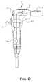
- FIG. 3is a left side elevational view of the interlock device handset of the present invention.
- FIG. 4is an exploded view of the interlock device handset of the present invention.
- FIG. 5is a front elevational view of a printed circuit board having a breath sampling housing mounted on a top portion thereof employed within the interlock device handset of the present invention
- FIG. 6is a rear elevational view of the printed circuit board having the breath sampling housing mounted on the top portion thereof employed within the interlock device handset of the present invention
- FIG. 7is an exploded view of the breath sampling housing
- FIG. 8is a left side elevational view of the breath sampling housing
- FIG. 9is a cross-sectional view of the breath sampling housing along lines 9 — 9 of FIG. 8 ;
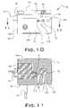
- FIG. 10is a right side elevational view of the breath sampling housing
- FIG. 11is a is a cross sectional view of the breath sampling housing along lines 11 — 11 of FIG. 10 ;
- FIG. 12is a left side elevational view, partially in section, of the interlock device handset of the present invention.
- FIG. 13is a perspective view of a base unit employed with the interlock device of the present invention.
- FIG. 14is an exploded view of the base unit employed with the interlock device of the present invention.
- FIG. 15is a flow diagram illustrating the manner in which air flows through the handset and the breath sampling housing and how certain measuring components of the interlock device of the present invention interact;
- FIG. 16is a first graph illustrating a raw alcohol measurement (test result) versus breath flow (pressure) through the handset.
- FIG. 17is a second graph illustrating a pressure correction factor curve (offset) correlating to a raw pressure value.
- FIG. 2illustrates a front view of handset 10 whereby a display screen 12 is clearly seen.
- Display screen 12is an LED display screen (see FIG. 5 ) coupled to a printed circuit board (to be discussed hereinafter) enclosed within handset 10 which provides for a plurality of messages to be displayed thereon, including, but not limited to, “Warm Up”, “Blow Now”, “Fail” and “Pass”.
- LED display screen 12is covered by a tinted translucent cover 14 so that the messages on display screen 12 are visible but all other components mounted on the circuit board are not visible.
- handset 10has a conical shape thereby permitting handset 10 to be easily gripped by a person utilizing the interlock device.
- handset 10includes a “power-on” button 16 that is first engaged to operate the interlock device of the present invention.
- Button 16is located on a top portion 20 of handset 10 .
- button 16sends a signal to a microprocessor which “wakes-up” handset 10 and the interlock device.
- the interlock device of the present inventioncan be programmed to “time out” after a pre-determined amount of time has elapsed thereby eliminating the need for the interlock device to be powered down after each use.
- the interlock deviceessentially enters a sleep mode and waits for its next instruction to operate.
- the interlock devicecan be programmed so that it can be powered down by depressing button 16 again or simply shut off when the power source of the interlock device and handset 10 is shut down (i.e., power to an automobile in which the interlock device of the present invention is connected is shut off).
- Handset 10also includes a “power on” indicator LED (not shown) positioned underneath a small cover 18 positioned juxtaposed button 16 on handset top portion 20 . The indicator LED will illuminate a color, such as green, to indicate that power is being received by handset 10 .
- handset 10includes a front and back housing member, 22 and 24 respectively, which are used to enclose a printed circuit board (PCB) 25 within handset 10 .
- PCB 25contains various electrical components used for analyzing a breath sample of which will be discussed in further detail hereinafter.
- the two housing members 22 and 24are attached by a plurality of screws entering back housing member 24 and inserting into front housing member 22 .
- the “power-on” indicator LED, positioned underneath cover 18 , and push button 16as seen in FIG. 1 , communicate with PCB 25 through ribbon connector 17 .
- handset 10also includes a mouthpiece 26 used to place between the lips of a person utilizing the interlock device of the present invention.
- Mouthpiece 26axially aligns with a breath intake channel 28 which is formed through handset top portion 20 (see FIG. 12 ).
- mouthpiece 26is secured by friction in handset top portion 20 so that it can be easily removed and replaced when necessary by a small amount of force but is retained if handset 10 is moved around.
- a small annular mounting peg 15is disposed along handset back housing member 24 for hanging handset 10 on a reciprocal clip (not shown) within a vehicle.
- a breath sampling housing 30contains components used to sample the alcohol content of a breath sample blown into mouthpiece 26 .
- Breath sampling housing 30contains a breath sampling channel 32 (see FIG. 9 ) which axially aligns with mouthpiece 26 and is positioned intermediate an entrance port 34 and an exhaust port 36 of handset breath intake channel 28 (see FIG. 12 ).
- gas sampleenters handset breath intake channel entrance port 34 , permits a portion of said gas sample to enter the breath sampling channel 32 of breath sampling housing 30 , thereafter expelling all remaining portions of said gas sample out through handset breath intake channel exhaust port 36 .
- gas samplemeans a human breath possibly containing a level of alcohol vapors within the breath.
- breath sampling housing 30mounts on a top portion 38 of PCB 25 .
- Power to all components of breath sampling housing 30is supplied via a first connector 40 mounted on a back side 48 of PCB 25 .
- first connector 40is a removable jumper, although first connector could be a soldered contact.
- PCB 25receives its supply of power via a second connector 42 along a bottom portion 44 of PCB 25 which connects to a power source (i.e., battery—not shown) of an automobile or vehicle in which the interlock device is installed.
- second connector 42is a soldered contact, although second connector could be constructed as a removable jumper.
- PCB 25also includes a pressure transducer 46 mounted on PCB 25 back side 48 .
- Pressure transducer 46has a capillary tube 52 connected thereto (see FIG. 6 ) which feeds to breath sampling housing 30 (see FIG. 5 ). As shown in FIG. 15 , capillary tube 52 directs a small portion of the gas sample entering breath sampling housing to pressure transducer 46 to determine a pressure value of said gas sample. As will be discussed in further detail hereinafter, the measured pressure value of the gas sample is used to calculate an offset, through an algorithmic calculation, which in turn is used to provide compensation such that an accurate measurement of the alcohol content of the gas sample can be provided.
- PCB 25also includes a speaker 162 and a battery 164 , both coupled to PCB 25 along front side 50 .
- Speaker 162provides audio signaling for power-up and power-down procedures, an indicator for test results, an indicator for circumvention warnings and as an indicator that a rolling repeat test may be required.
- Battery 164supports a microprocessor of handset 10 (to be discussed in further detail hereinafter) and a clock (not shown) for handset 10 , both located on PCB 25 .
- Breath sampling housing 30includes a body portion 54 having a first channel 56 (see also FIG. 9 ) formed there through.
- Body portion 54is rectangular-shaped and includes a front end 58 and a top side 60 which has a cut-away portion 62 which seats a fuel cell 64 .
- fuel cell 64is a dry electrochemical fuel cell which operates by producing an electrical signal in response to a chemical reaction across the cell (the difference in the chemical reaction).
- Fuel cell 64is employed as an alcohol specific fuel cell.
- a dry electrochemical fuel cellis preferred over other fuel cells, such as thermo-based cells, although nothing herein limits the use of other known fuel cells that are capable of measuring the presence of alcohol.
- a second channel 68formed in body portion 54 which communicates with a passageway 70 and an entrance port 74 of fuel cell 64 .
- Passageway 70also seats a water filter 72 .
- Of the two electrical contacts 80 of fuel cell 64one provides power to fuel cell 64 while the other provides a pathway to send an electrical signal to PCB 25 .
- Water filter 72sits within passageway 70 and is held down by a gasket 82 which in turn is held down by a cover 84 .
- Cover 84attaches to body portion top side 60 by screws and also works to enclose and retain fuel cell 64 seated within cut-away portion 62 .
- Cover 84has a small aperture 86 formed along a right side wall 88 for receiving a distal end 90 of capillary tube 52 .
- a proximal end 92 of capillary tube 52is attached to pressure transducer 46 at an entrance port 94 thereon (see FIG. 6 ).
- Aperture 86communicates with passageway 70 for permitting a small portion of the gas sample to reach pressure transducer 46 through capillary tube 52 .
- Water filter 72is constructed from a cork-like or sponge-like material and works to eliminate water from the gas sample while permitting alcohol vapors to pass through to fuel cell 64 . The elimination or reduction of water from the gas sample ensures that fuel cell 64 is not exposed to excessive moisture which can lead to cell saturation which in turn can lead to faulty readings and cell failure.
- breath sampling housingalso contains a solenoid valve 98 having a mounting head 100 and a valve portion 102 in air passageway communication.
- Solenoid valve 98is a normally open valve.
- Mounting head 100has an outwardly extending peg (not shown) on an inner surface for inserting within a peg receiving aperture 104 formed in a right side wall 106 of breath sampling housing body portion 54 .
- Two screw bores 118are also formed in breath sampling housing body portion right side wall 106 for receiving a pair of screws and retaining solenoid valve 98 up against body portion 54 .
- breath sampling housing body portion right side wall 106Also formed through breath sampling housing body portion right side wall 106 , are an entrance channel 108 and an exhaust channel 110 for solenoid valve 98 which axially align with reciprocal entrance and exhaust ports (not shown) formed through the inner surface of solenoid valve mounting head 100 which then communicates with valve portion 102 .
- Entrance channel 108leads from passageway 70 behind water filter 72
- exhaust channel 110leads to fuel cell entrance port 74 (see FIG. 9 ).
- Solenoid valve 98also contains a pair of electrical contacts 112 , a first for providing power to solenoid valve 98 and a second for receiving an electrical signal which forces the valve to remain open and then to close for a finite time as instructed by a microprocessor (to be discussed in further detail hereinafter).
- solenoid valve 98is normally open. This acts as a “fail-safe” feature in case the valve fails. It is not desirable for the interlock device of the present invention to a give a false negative reading, or a “Pass” result, if in fact the blood alcohol content of the test taker has exceeded the predetermined threshold. If the valve is closed and has failed, then the test result may be a “Pass” when in fact the test taker is actually intoxicated, or has at least exceeded the threshold setting for the particular interlock device, due to the fact that fuel cell 64 would not see any alcohol vapors pass across the cell. A false negative may then permit the vehicle to be operated by an intoxicated driver.
- the interlock device of the present inventionincludes a valve open/close position sensor to indicate if the valve is not in its correct position.
- the interlock devicewould be programmed such that a test could not be administered if the valve is in the wrong position.
- solenoid valve 98is closed during the initialization process (“Warm-Up”), but then returns to a normally open state.
- a temperature sensor bore 114is also formed through breath sampling housing body portion right side wall 106 directly below valve portion 102 of solenoid valve 98 . Temperature sensor bore 114 is in communication with breath sampling channel 32 .
- a breath temperature sensor 116such as a thermistor, is inserted within bore 114 and is used to measure the temperature of the gas sample entering breath sampling channel 32 (see FIG. 5 ), thereby ensuring that the gas sample is an actual human breath from that moment in time and not some other gas used in an attempt to circumvent the interlock device.
- Breath temperature sensor 116also has a pair of electrical contacts 120 for providing power to sensor 116 and for providing a pathway for a signal generated in response to a temperature measurement made by sensor 116 . The two electrical contacts 120 are bundled together and couple to PCB 25 at first connector 40 .
- breath sampling housing 30also includes a housing temperature sensor 122 and a housing heater 124 .
- Housing temperature sensor 122mounts along a left side wall 126 of body portion 54 while housing heater 124 mounts along a bottom side 128 of body portion.
- housing temperature sensor 122is also a thermistor and housing heater 124 is a strip of heating tape.
- a strip of tape(not shown) can be wrapped around body portion top and bottom sides, 60 and 128 , and left side wall 126 to enclose and retain housing temperature sensor 122 and housing heater 124 .
- Housing temperature sensor 122also has a pair of electrical contacts 130 for providing power thereto and a pathway for an electrical signal in response to a temperature measurement made by temperature housing sensor 122 .
- Housing heater 124has a pair of electrical leads 132 for providing power thereto. Both the pair of contacts and the pair of leads, 130 and 132 respectively, are bundled together and connect to PCB 25 at first connector 40 . Housing temperature sensor 122 is used to monitor the current temperature of breath sampling housing 30 while housing heater 124 is used to warm up breath sampling housing 30 and to hold the temperature of housing 30 slightly above human body temperature and thereby avoid the development of condensation.
- the interlock device of the present inventionincludes a microprocessor 134 (mounted on PCB 25 within handset 10 ). Microprocessor 134 is coupled to LED display screen 12 . Those components enclosed within breath sampling housing 30 are shown to be within the dotted lines represented on FIG. 15 , while those components attached to the outer walls of breath sampling housing are shown to be positioned juxtaposed the same dotted lines.
- a gas sample from a human breathenters breath sampling channel 32 of breath sampling housing 30 from breath intake channel entrance port 34 .
- a portion of the gas sampleenters passageway 70 and is filtered by water filter 72 .
- a portion of that gas sampleis directed away from passageway 70 through aperture 86 , into capillary 52 and into pressure transducer 46 through pressure transducer entrance port 94 whereby a pressure reading is measured.
- the remaining water filtered gas sampleis expelled from passageway 70 through entrance channel 108 and into solenoid valve 98 . If the valve is open, the gas sample is permitted to pass through exhaust channel 110 and into fuel cell 64 at fuel cell entrance port 74 . Any remaining un-needed gas sample is then expelled through fuel cell exhaust port 78 .
- solenoid valve 98fuel cell 64 and pressure transducer 46 are all in communication with microprocessor 134 .
- Microprocessor 134first initiates a warm-up procedure before any test is taken to stabilize handset 10 . Not until LED display screen 12 says “Blow Now” (or some other like instruction), can a test be taken. At such time, a person blows into mouthpiece 26 (see FIG. 3 ).
- Microprocessorinstructs solenoid valve 98 to remain open for a finite period of time, for example, between 100 and 700 mS in response to detecting a minimal pressure measurement. This range allows for the accommodation of variable conditions.
- Fuel cell 64measures the alcohol content of that gas sample and sends this measured reading to microprocessor 134 .
- microprocessor 134takes a series of pressure measurements from pressure transducer 46 .
- An algorithm embedded upon microprocessor 134then calculates an offset value to apply to the measured value taken by fuel cell 64 to calculate a more accurate reading of the blood alcohol content of the gas sample.
- the results of this processare then used to determine whether the vehicle's ignition system can be engaged if the vehicle is powered off.
- a “Pass” or “Fail” messageappears on LED screen display 12 depending on the results of the test. If the vehicle's power system is already running, then the results of the test will be displayed on LED display screen 12 , but the power to the vehicle will not he disengaged.
- the novel interlock device of the present inventioncan sound the horn and flash the lights, if so desired, to draw attention to the rolling repeat test violator.
- a dated data logis stored on microprocessor 134 in handset 10 and is used for recording a plurality of different events, including, but not limited to, when the interlock device was powered on and powered off, if any attempts at circumvention was attempted, results of all tests, if the vehicle's engine was idling for any amount of time, and if required tests where not performed when instructed by the interlock device (i.e., rolling repeat tests).
- the information in the data logcan be downloaded to a PC, a laptop, personal digital assistant (PDA) or any other kind of like computing and digital storage device by interfacing with handset 10 through a data port 136 located along a side portion of handset 10 (see FIGS. 3 , 4 and 6 ).
- data port 136is a mini USB B port.
- any type of known data portcan be employed.
- a wireless transceivercan be employed to download data from the data log using any known wireless transmitting technology.
- uploadscan also be effected through data port 136 for calibrating the interlock device, for performing maintenance, for setting preferences and for updating the software embedded on microprocessor 134 .
- the interlock device of the present inventionalso includes a base unit 138 .
- base unit 138includes a top and bottom housing member, 140 and 142 respectively, enclosing a printed circuit board (PCB) 144 .
- PCBprinted circuit board
- Base unit 138is coupled to handset 10 by a detachable cable 148 which terminates on PCB 144 at connector 146 .
- PCB 144has a pair of relays 150 mounted upon a top side 166 of PCB 144 . The pair of relays 150 are connected in series with a starter mechanism (not shown) and the light and horn switching system of a vehicle.
- Relays 150react in accordance with instructions received from microprocessor 134 which processes the gas sample test (sobriety test). Relays 150 permit the starting mechanism of a vehicle to operate if a person has passed the sobriety test and preclude the starting mechanism if the person has failed the sobriety test. Relays 150 are also used to sound the horn and flash the lights of the vehicle in response to a failed test during rolling operation of the vehicle. Additional relays could be employed within base unit 138 to operate or preclude operation of other features of a vehicle in response to a pass or failed test or to signal law enforcement or a supervising agency in response to a failed test.
- the threshold of the sobriety testis adjustable, it is set by the manufacturer or supervising agency and can not be adjusted by the user of the interlock device.
- the sobriety threshold settingis effected by interfacing with a computing device through data port 136 . In the preferred embodiment, the sobriety threshold is set at 0.03%.
- Base unit 138can be mounted within the vehicle in a non-obtrusive location by a plurality of screws inserted through mounting wings 152 .
- Top and bottom housing members, 140 and 142 respectively, of base unit 144include a plurality of heat dissipation vents 154 formed throughout the outer peripheral of housing members 140 and 142 .
- PCB 144is provided power by cable 156 connected to a power source (not shown) of the vehicle in which the interlock device is mounted.
- a pair of auxiliary connectors, AUX 1 and AUX 2 , 158 and 160 respectively,are coupled to PCB 144 for other interfacing uses, such as, for example, personal identification and position location features.
- AUX 1 and AUX 2are RS-232 ports, although other data interfacing ports can be employed.
- personal identification featuresinclude, but are not limited to, retina scans, voice recognition, fingerprint verification and dental imprints.
- position location featuresinclude cellular and satellite phone interface, GPS (Global Positioning System), LORAN and unique beacon indicators.
- pressure transducer 46does not control the opening and closing of solenoid valve 98 as seen in the prior art inventions.
- pressure transducershave been used to provide a constant volume of air to a fuel cell based upon fluctuating pressure by controlling the opening and closing of a valve upstream from a fuel cell.
- pressure transducer 46 and solenoid valve 98operate independently from one another to provide a variable flow to fuel cell 64 based upon a threshold pressure being exceeded or not being met.
- An algorithmic offsetis calculated in microprocessor 134 to provide a pressure compensated alcohol result that is constant, without regard to pressure, as shown in FIG. 16 as a flat line.
- a correction factor, or offsetcalculated by microprocessor 134 through the algorithm, is used to adjust the test result due to varying breath flow through handset 10 .
- Pressure transducer 46does not effect how long solenoid valve 98 stays open or how much breath flow is permitted to pass through to fuel cell 64 .
- Pressure transducer 46instead makes a measurement of the current breath flow, or pressure, and feeds that measurement to microprocessor 134 to calculate the offset. This prohibits someone from trying to fool the interlock device by introducing a low pressurized breath flow. Further, this novel approach to sampling the breath ensures that a high pressured breath flow does not saturate the fuel cell and give a false positive result.
- the novel interlock device of the present inventioncan be removed from a vehicle and brought within the confines of a residence or commercial establishment. Accordingly, the novel interlock device of the present invention could be used as a home monitoring device.
- handset 10couples to an alternate power source within the residence or commercial establishment through a power coupler.
- Base unit 138can remain in the vehicle since the output relays will not be used to control a vehicle starter or ignition system. However, signaling devices within the home may be controlled and would therefore warrant removal of base unit 138 from the vehicle to be wired to said signaling devices.
- Handset 10can easily interface with a home computer through data port 136 to download data logs and upload preferences and settings and software updates and to conduct scheduled calibration and/or maintenance.
- This alternate devicewould work in a home monitoring environment is as follows: the offender stands in front of a web cam while the interlock device is connected to a home computer; software installed on the home computer takes a digital picture or movie of the offender taking the test; the time is stamped on the picture or movie along with the results of the test; the test results are then transmitted to a host computer (supervising agency) over the Internet, by a proprietary hard-wired connection or by wireless transmission.
- the softwarecan additionally be programmed to immediately notify a predetermined monitoring service or agency in the event of a failed or refused test.
Landscapes
- Engineering & Computer Science (AREA)
- Health & Medical Sciences (AREA)
- Life Sciences & Earth Sciences (AREA)
- Chemical & Material Sciences (AREA)
- Molecular Biology (AREA)
- Biomedical Technology (AREA)
- Physics & Mathematics (AREA)
- Urology & Nephrology (AREA)
- Biochemistry (AREA)
- Transportation (AREA)
- Biophysics (AREA)
- Hematology (AREA)
- Combustion & Propulsion (AREA)
- Food Science & Technology (AREA)
- Medicinal Chemistry (AREA)
- Analytical Chemistry (AREA)
- Mechanical Engineering (AREA)
- General Health & Medical Sciences (AREA)
- General Physics & Mathematics (AREA)
- Immunology (AREA)
- Pathology (AREA)
- Investigating Or Analysing Biological Materials (AREA)
- Auxiliary Drives, Propulsion Controls, And Safety Devices (AREA)
- Measurement Of The Respiration, Hearing Ability, Form, And Blood Characteristics Of Living Organisms (AREA)
Abstract
Description
Claims (38)
Priority Applications (2)
| Application Number | Priority Date | Filing Date | Title |
|---|---|---|---|
| US10/485,041US7204335B2 (en) | 2003-10-31 | 2003-10-31 | Vehicle sobriety interlock device |
| US11/683,115US7451852B2 (en) | 2003-10-31 | 2007-03-07 | Vehicle sobriety interlock system with personal identification element |
Applications Claiming Priority (2)
| Application Number | Priority Date | Filing Date | Title |
|---|---|---|---|
| PCT/US2003/034650WO2005051700A1 (en) | 2003-10-31 | 2003-10-31 | Vehicle sobriety interlock device |
| US10/485,041US7204335B2 (en) | 2003-10-31 | 2003-10-31 | Vehicle sobriety interlock device |
Related Parent Applications (1)
| Application Number | Title | Priority Date | Filing Date |
|---|---|---|---|
| PCT/US2003/034650Continuation-In-PartWO2005051700A1 (en) | 2003-10-31 | 2003-10-31 | Vehicle sobriety interlock device |
Related Child Applications (1)
| Application Number | Title | Priority Date | Filing Date |
|---|---|---|---|
| US11/683,115Continuation-In-PartUS7451852B2 (en) | 2003-10-31 | 2007-03-07 | Vehicle sobriety interlock system with personal identification element |
Publications (2)
| Publication Number | Publication Date |
|---|---|
| US20050241871A1 US20050241871A1 (en) | 2005-11-03 |
| US7204335B2true US7204335B2 (en) | 2007-04-17 |
Family
ID=34632382
Family Applications (1)
| Application Number | Title | Priority Date | Filing Date |
|---|---|---|---|
| US10/485,041Expired - LifetimeUS7204335B2 (en) | 2003-10-31 | 2003-10-31 | Vehicle sobriety interlock device |
Country Status (5)
| Country | Link |
|---|---|
| US (1) | US7204335B2 (en) |
| EP (1) | EP1678001B1 (en) |
| AU (1) | AU2003286799C1 (en) |
| CA (1) | CA2539073C (en) |
| WO (1) | WO2005051700A1 (en) |
Cited By (29)
| Publication number | Priority date | Publication date | Assignee | Title |
|---|---|---|---|---|
| US20060182661A1 (en)* | 2005-02-11 | 2006-08-17 | Aquila Albert B | Blood alcohol content (BAC) level actuated lock box |
| US20060202842A1 (en)* | 2005-02-11 | 2006-09-14 | Stephanie Sofer | Car alcohol monitoring system |
| US20100012417A1 (en)* | 2008-07-17 | 2010-01-21 | Consumer Safety Technology, Inc. | Ignition interlock breathalyzer |
| US20100212986A1 (en)* | 2009-02-23 | 2010-08-26 | Michael D. Roth | Methods for providing secure and transparent cached ignition interlock data |
| US20110252839A1 (en)* | 2010-04-16 | 2011-10-20 | Stevens Stacy Joan | Biased open key lockbox system, and method of use thereof |
| US20120031166A1 (en)* | 2010-08-03 | 2012-02-09 | Mesa Digital, LLC. | Beverage disguise for hand held breathalyzer interface of ignition interlock device |
| DE102011106410B3 (en)* | 2011-07-02 | 2012-08-02 | Dräger Safety Ag & Co.Kgaa | Breath alcohol content meter |
| WO2013191633A1 (en)* | 2012-06-21 | 2013-12-27 | Alco Systems Sweden Ab | Apparatus and method for heating a breath alcohol testing device |
| US8941501B1 (en) | 2013-07-24 | 2015-01-27 | Travis Debijl | System to prevent drunken driving |
| US8957771B2 (en) | 2008-07-17 | 2015-02-17 | Consumer Safety Technology, Inc. | Apparatus, system, and method for implementing and monitoring breath alcohol testing programs, usually from a fixed point location, such as a home |
| US20150197151A1 (en)* | 2014-01-15 | 2015-07-16 | 1A Smart Start, Inc. | Programmable Fuel Cell and Grommet Warm-Up Circuitry and Methods for Use in Sobriety Testing Systems |
| US9404286B2 (en) | 2010-04-16 | 2016-08-02 | Stacy Joan STEVENS | Key trapping device, system, and method of use thereof |
| US9772318B1 (en) | 2013-07-31 | 2017-09-26 | Michael Lyon | Interlock data collection and calibration system |
| US9788772B2 (en) | 2013-01-31 | 2017-10-17 | KHN Solutions, Inc. | Wearable system and method for monitoring intoxication |
| US10034635B2 (en) | 2013-01-31 | 2018-07-31 | KHN Solutions, Inc. | Method and system for monitoring intoxication |
| US10302628B2 (en) | 2014-01-22 | 2019-05-28 | KHN Solutions, Inc. | Method and system for remotely monitoring intoxication |
| US10436770B2 (en) | 2013-07-31 | 2019-10-08 | 1A Smart Start, Llc | Automated calibration station for ignition interlock devices |
| US10488398B2 (en) | 2015-12-17 | 2019-11-26 | #1 A Lifesafer, Inc. | Chemical impairment detection system with an integrated, multi-function breath chamber |
| US10596903B2 (en) | 2015-10-13 | 2020-03-24 | Consumer Safety Technology, Llc | Networked intoxication vehicle immobilization |
| US10663440B2 (en) | 2016-09-09 | 2020-05-26 | Consumer Safety Technology, Llc | Secure data handling in a breath alcohol calibration station |
| US10877008B2 (en) | 2016-09-09 | 2020-12-29 | Consumer Safety Technology, Llc | Reference gas management in a breath alcohol calibration station |
| US11253196B2 (en) | 2018-03-22 | 2022-02-22 | KHN Solutions, Inc. | Method and system for transdermal alcohol monitoring |
| US11324449B2 (en) | 2018-03-22 | 2022-05-10 | KHN Solutions, Inc. | Method and system for transdermal alcohol monitoring |
| US11393588B2 (en) | 2013-01-31 | 2022-07-19 | KHN Solutions, Inc. | Method and system for monitoring intoxication |
| US20230040522A1 (en)* | 2021-08-05 | 2023-02-09 | Hyundai Mobis Co., Ltd. | Drunk driving prevention system with bypass mode and drunk driving prevention method using the system |
| US11602306B2 (en) | 2021-01-12 | 2023-03-14 | KHN Solutions, Inc. | Method and system for remote transdermal alcohol monitoring |
| US20230417735A1 (en)* | 2017-10-12 | 2023-12-28 | Pivot Health Technologies Inc. | Breath sensor apparatus and methods of use |
| US12311759B1 (en) | 2022-02-02 | 2025-05-27 | Consumer Safety Technology, Llc | Wireless vehicle interface for immobilization system |
| US12343133B1 (en) | 2023-10-27 | 2025-07-01 | Khn Solutions, Llc | Method and system for detecting and maintaining performance of an alcohol sensing device |
Families Citing this family (29)
| Publication number | Priority date | Publication date | Assignee | Title |
|---|---|---|---|---|
| US7451852B2 (en)* | 2003-10-31 | 2008-11-18 | Sherman Enterprises, Inc. | Vehicle sobriety interlock system with personal identification element |
| NL1030119C2 (en) | 2005-10-05 | 2007-04-06 | Intertruck Benelux B V | Method and device for detecting alcohol in a person. |
| DE102006018970B3 (en)* | 2006-04-25 | 2007-05-03 | Dräger Safety AG & Co. KGaA | Breath alcohol measuring instrument e.g. for alcohol in breath, has evaluation and control unit receiving measuring signals of sensors and operates sampling system which has bellows and piezo actuator |
| US7925508B1 (en) | 2006-08-22 | 2011-04-12 | Avaya Inc. | Detection of extreme hypoglycemia or hyperglycemia based on automatic analysis of speech patterns |
| US7962342B1 (en)* | 2006-08-22 | 2011-06-14 | Avaya Inc. | Dynamic user interface for the temporarily impaired based on automatic analysis for speech patterns |
| US8041344B1 (en) | 2007-06-26 | 2011-10-18 | Avaya Inc. | Cooling off period prior to sending dependent on user's state |
| JP4650557B2 (en)* | 2008-11-07 | 2011-03-16 | 株式会社デンソー | Operation restriction system |
| ATE518689T1 (en)* | 2009-06-16 | 2011-08-15 | Draeger Safety Ag & Co Kgaa | ALCOHOL INTERLOCK SYSTEM WITH WIRELESS DATA TRANSMISSION AND SECURITY FUNCTION |
| JP6023075B2 (en) | 2010-12-20 | 2016-11-09 | アルコ システムズ スウェーデン アーベーAlco Systems Sweden Ab | Method and apparatus for measuring respiratory alcohol concentration |
| US8640813B2 (en)* | 2011-08-24 | 2014-02-04 | Nicholas G. DOINOFF | Ignition interlock device with rolling retest and motion detector |
| CN104039577B (en) | 2011-08-29 | 2018-05-15 | 汽车交通安全联合公司 | System for the non-intrusion measurement of the analyte in vehicle driver |
| US9296298B2 (en)* | 2012-03-12 | 2016-03-29 | Transbiotec, Inc. | Alcohol detection system for vehicle driver testing with integral temperature compensation |
| ITFI20120102A1 (en)* | 2012-05-30 | 2013-12-01 | Nacci Felli Mario E Nacci Gaetano | DEVICE FOR CONTROL, VALIDATION AND STORAGE IN A REMOTE SERVER OF THE RELATIVE DATA, OF THE ALCOHOLIC ZERO RATE OBLIGATION (LAW 120 OF 29.07.2010) REFERRED TO THE DRIVERS OF PUBLIC TRANSPORT, HEAVY TAXI AND TRUCKS, DURING THEIR TU |
| SE537211C2 (en) | 2012-06-19 | 2015-03-03 | Alco Systems Sweden Ab | Procedure for measuring alcohol exhalation concentration and apparatus therefore |
| US8792687B2 (en)* | 2012-06-29 | 2014-07-29 | International Business Machines Corporation | Providing an ID-verified blood test |
| US9057691B2 (en)* | 2012-08-03 | 2015-06-16 | Alcotek, Inc. | Fuel cell housing for use in an alcohol breath tester |
| SE536784C2 (en)* | 2012-08-24 | 2014-08-05 | Automotive Coalition For Traffic Safety Inc | Exhalation test system |
| SE536782C2 (en) | 2012-08-24 | 2014-08-05 | Automotive Coalition For Traffic Safety Inc | Exhalation test system with high accuracy |
| US20140165698A1 (en)* | 2012-12-17 | 2014-06-19 | Tanita Corporation | Mouthpiece of breath component measuring device, breath component measuring assembly, breath component measuring device, and breath component measuring system |
| US20140335905A1 (en)* | 2013-05-07 | 2014-11-13 | Swaive Corporation | Portable device for measuring blood alcohol level by using a mobile device susch as a phone, tablet or laptop |
| JP6553614B2 (en) | 2013-08-27 | 2019-07-31 | オートモーティブ コアリション フォー トラフィック セーフティ, インコーポレイテッド | System and method for controlling vehicle ignition using biometric data |
| US20160318521A1 (en)* | 2014-01-22 | 2016-11-03 | KHN Solutions, Inc. | Method and system for drunk driving prevention |
| WO2016040771A1 (en)* | 2014-09-12 | 2016-03-17 | Spec Sensors, Llc | Breath sampling devices and methods of breath sampling using sensors |
| GB201518600D0 (en) | 2015-10-20 | 2015-12-02 | Now Group Uk Ltd | A breathalyser coaching and setup methodology |
| CN205333657U (en)* | 2015-10-27 | 2016-06-22 | 深圳市杰仕博科技有限公司 | Multifunctional alcohol tester |
| US11104227B2 (en) | 2016-03-24 | 2021-08-31 | Automotive Coalition For Traffic Safety, Inc. | Sensor system for passive in-vehicle breath alcohol estimation |
| US10563998B1 (en) | 2016-08-03 | 2020-02-18 | Nelson T. Rivera | Community-based transportation services system and method |
| CN108918196A (en)* | 2018-09-17 | 2018-11-30 | 安徽水韵环境检测有限公司 | Water quality detection technique is carried out using multi-point water quality sampling |
| US11513070B2 (en) | 2019-06-12 | 2022-11-29 | Automotive Coalition For Traffic Safety, Inc. | System for non-invasive measurement of an analyte in a vehicle driver |
Citations (24)
| Publication number | Priority date | Publication date | Assignee | Title |
|---|---|---|---|---|
| US3764270A (en) | 1971-04-23 | 1973-10-09 | Borg Warner | Breath testing system |
| US3824538A (en) | 1973-06-08 | 1974-07-16 | Shelcy Mullins | Motor vehicle operator monitoring system |
| US3831707A (en) | 1973-08-13 | 1974-08-27 | Nissan Motor | System to prevent drunken driving |
| US4592443A (en)* | 1983-02-01 | 1986-06-03 | Jack Simon | Sobriety interlock |
| US4697666A (en) | 1986-09-16 | 1987-10-06 | Guardian Interlock Systems, Inc. | Sobriety interlock with time-locked interlock mode |
| US4749553A (en)* | 1987-04-08 | 1988-06-07 | Life Loc, Inc. | Breath alcohol detector with improved compensation for environmental variables |
| US4809810A (en)* | 1986-05-01 | 1989-03-07 | Autosense Corporation | Breath alcohol analyzer |
| US4901058A (en) | 1988-06-17 | 1990-02-13 | Guardian Technologies, Inc. | Sobriety interlock with bypass detection |
| US4902628A (en) | 1988-08-24 | 1990-02-20 | Guardian Technologies, Inc. | Apparatus and method to deter circumvention of a breath sobriety test |
| US4912458A (en) | 1988-06-17 | 1990-03-27 | Guardian Technologies, Inc. | Sobriety interlock with service reminder |
| US4926164A (en) | 1987-12-15 | 1990-05-15 | Lion Analytics Pty. Limited | Vehicle breath monitoring device |
| US5291898A (en)* | 1992-05-22 | 1994-03-08 | Alcotek, Inc. | Breath alcohol device |
| US5426415A (en)* | 1993-06-21 | 1995-06-20 | Consumer Safety Technology | Breath analyzer for use in automobile ignition locking systems |
| US5805079A (en) | 1994-02-18 | 1998-09-08 | Lemelson; Jerome H. | Motor vehicle performance monitor and method |
| US6026674A (en)* | 1998-08-20 | 2000-02-22 | Smart Start Inc. | Apparatus and method for determining a person's sobriety |
| US6075444A (en) | 1997-09-25 | 2000-06-13 | Drager Sicherheitstechnik Gmbh | Arrangement for blocking the operation by an operator of a vehicle or a machine |
| US6234006B1 (en)* | 1998-03-20 | 2001-05-22 | Cyrano Sciences Inc. | Handheld sensing apparatus |
| US20020084130A1 (en) | 2000-04-12 | 2002-07-04 | Viken Der Ghazarian | Breathalyzer with voice recognition |
| US6512465B2 (en) | 2000-05-17 | 2003-01-28 | Omega Patents, L.L.C. | Vehicle tracker including stationary time determination and associated methods |
| US6609068B2 (en) | 2000-02-22 | 2003-08-19 | Dow Global Technologies Inc. | Personal computer breath analyzer for health-related behavior modification and method |
| US20030176803A1 (en) | 2002-03-14 | 2003-09-18 | Edward Gollar | Personal breath tester |
| US20030183437A1 (en)* | 2002-03-28 | 2003-10-02 | Mendoza Joaquin L. | Breath measurement instrument and breath alcohol interlock device incorporating same |
| US20040239510A1 (en)* | 2004-04-07 | 2004-12-02 | Harry Karsten | Breath alcohol detection system with identity verification |
| US6853956B2 (en)* | 2003-02-11 | 2005-02-08 | Smart Start Inc. | Sobriety testing apparatus having OBD-II connection capability |
Family Cites Families (6)
| Publication number | Priority date | Publication date | Assignee | Title |
|---|---|---|---|---|
| US4292978A (en)* | 1979-12-26 | 1981-10-06 | Guth Richard U | Breath test mouthpiece |
| US4678057A (en)* | 1986-01-16 | 1987-07-07 | Autosense Corporation | Breath alcohol analyzer |
| US4738333A (en) | 1986-09-16 | 1988-04-19 | Guardian Technologies, Inc. | Sobriety interlock with unsupervised confirmation of operator identity |
| GB8711573D0 (en)* | 1987-05-15 | 1987-06-17 | Lion Lab Ltd | Measuring apparatus |
| US5303575A (en)* | 1993-06-01 | 1994-04-19 | Alcotech Research Inc. | Apparatus and method for conducting an unsupervised blood alcohol content level test |
| US6556905B1 (en)* | 2000-08-31 | 2003-04-29 | Lisa M. Mittelsteadt | Vehicle supervision and monitoring |
- 2003
- 2003-10-31WOPCT/US2003/034650patent/WO2005051700A1/enactiveApplication Filing
- 2003-10-31USUS10/485,041patent/US7204335B2/ennot_activeExpired - Lifetime
- 2003-10-31AUAU2003286799Apatent/AU2003286799C1/ennot_activeCeased
- 2003-10-31EPEP03778013.7Apatent/EP1678001B1/ennot_activeExpired - Lifetime
- 2003-10-31CACA002539073Apatent/CA2539073C/ennot_activeExpired - Lifetime
Patent Citations (28)
| Publication number | Priority date | Publication date | Assignee | Title |
|---|---|---|---|---|
| US4093945A (en)* | 1971-04-23 | 1978-06-06 | Collier Donald W | Breath testing system |
| US3764270A (en) | 1971-04-23 | 1973-10-09 | Borg Warner | Breath testing system |
| US3824538A (en) | 1973-06-08 | 1974-07-16 | Shelcy Mullins | Motor vehicle operator monitoring system |
| US3831707A (en) | 1973-08-13 | 1974-08-27 | Nissan Motor | System to prevent drunken driving |
| US4592443A (en)* | 1983-02-01 | 1986-06-03 | Jack Simon | Sobriety interlock |
| US4809810A (en)* | 1986-05-01 | 1989-03-07 | Autosense Corporation | Breath alcohol analyzer |
| US4697666A (en) | 1986-09-16 | 1987-10-06 | Guardian Interlock Systems, Inc. | Sobriety interlock with time-locked interlock mode |
| US4749553A (en)* | 1987-04-08 | 1988-06-07 | Life Loc, Inc. | Breath alcohol detector with improved compensation for environmental variables |
| US4926164A (en) | 1987-12-15 | 1990-05-15 | Lion Analytics Pty. Limited | Vehicle breath monitoring device |
| US4901058A (en) | 1988-06-17 | 1990-02-13 | Guardian Technologies, Inc. | Sobriety interlock with bypass detection |
| US4912458A (en) | 1988-06-17 | 1990-03-27 | Guardian Technologies, Inc. | Sobriety interlock with service reminder |
| US4902628A (en) | 1988-08-24 | 1990-02-20 | Guardian Technologies, Inc. | Apparatus and method to deter circumvention of a breath sobriety test |
| US5291898A (en)* | 1992-05-22 | 1994-03-08 | Alcotek, Inc. | Breath alcohol device |
| US5426415A (en)* | 1993-06-21 | 1995-06-20 | Consumer Safety Technology | Breath analyzer for use in automobile ignition locking systems |
| US5805079A (en) | 1994-02-18 | 1998-09-08 | Lemelson; Jerome H. | Motor vehicle performance monitor and method |
| US6075444A (en) | 1997-09-25 | 2000-06-13 | Drager Sicherheitstechnik Gmbh | Arrangement for blocking the operation by an operator of a vehicle or a machine |
| US6234006B1 (en)* | 1998-03-20 | 2001-05-22 | Cyrano Sciences Inc. | Handheld sensing apparatus |
| US6026674A (en)* | 1998-08-20 | 2000-02-22 | Smart Start Inc. | Apparatus and method for determining a person's sobriety |
| US6167746B1 (en) | 1998-08-20 | 2001-01-02 | Smart Start Inc. | Apparatus and method for determining a person's sobriety |
| US6609068B2 (en) | 2000-02-22 | 2003-08-19 | Dow Global Technologies Inc. | Personal computer breath analyzer for health-related behavior modification and method |
| US20020084130A1 (en) | 2000-04-12 | 2002-07-04 | Viken Der Ghazarian | Breathalyzer with voice recognition |
| US6512465B2 (en) | 2000-05-17 | 2003-01-28 | Omega Patents, L.L.C. | Vehicle tracker including stationary time determination and associated methods |
| US20030176803A1 (en) | 2002-03-14 | 2003-09-18 | Edward Gollar | Personal breath tester |
| US20030183437A1 (en)* | 2002-03-28 | 2003-10-02 | Mendoza Joaquin L. | Breath measurement instrument and breath alcohol interlock device incorporating same |
| US6792793B2 (en)* | 2002-03-28 | 2004-09-21 | Ignition Lock International | Breath measurement instrument and breath alcohol interlock device incorporating same |
| US6853956B2 (en)* | 2003-02-11 | 2005-02-08 | Smart Start Inc. | Sobriety testing apparatus having OBD-II connection capability |
| US20040239510A1 (en)* | 2004-04-07 | 2004-12-02 | Harry Karsten | Breath alcohol detection system with identity verification |
| US6967581B2 (en)* | 2004-04-07 | 2005-11-22 | Harry Karsten | Breath alcohol detection system with identity verification |
Cited By (66)
| Publication number | Priority date | Publication date | Assignee | Title |
|---|---|---|---|---|
| US20060182661A1 (en)* | 2005-02-11 | 2006-08-17 | Aquila Albert B | Blood alcohol content (BAC) level actuated lock box |
| US20060202842A1 (en)* | 2005-02-11 | 2006-09-14 | Stephanie Sofer | Car alcohol monitoring system |
| US7671752B2 (en)* | 2005-02-11 | 2010-03-02 | Stephanie Sofer | Car alcohol monitoring system |
| US20100012417A1 (en)* | 2008-07-17 | 2010-01-21 | Consumer Safety Technology, Inc. | Ignition interlock breathalyzer |
| US8957771B2 (en) | 2008-07-17 | 2015-02-17 | Consumer Safety Technology, Inc. | Apparatus, system, and method for implementing and monitoring breath alcohol testing programs, usually from a fixed point location, such as a home |
| US20110084820A1 (en)* | 2008-07-17 | 2011-04-14 | Consumer Safety Technology, Inc. | Ignition interlock breathalyzer |
| US7934577B2 (en) | 2008-07-17 | 2011-05-03 | Consumer Safety Technology, Inc. | Ignition interlock breathalyzer |
| US8059003B2 (en) | 2009-02-23 | 2011-11-15 | Safe Harbor, Llc | Methods for providing secure and transparent cached ignition interlock data |
| US20100212986A1 (en)* | 2009-02-23 | 2010-08-26 | Michael D. Roth | Methods for providing secure and transparent cached ignition interlock data |
| US20110252839A1 (en)* | 2010-04-16 | 2011-10-20 | Stevens Stacy Joan | Biased open key lockbox system, and method of use thereof |
| US9404286B2 (en) | 2010-04-16 | 2016-08-02 | Stacy Joan STEVENS | Key trapping device, system, and method of use thereof |
| US9260012B2 (en)* | 2010-08-03 | 2016-02-16 | Mesa Digital, Llc | Beverage disguise for hand held breathalyzer interface of ignition interlock device |
| US20120031166A1 (en)* | 2010-08-03 | 2012-02-09 | Mesa Digital, LLC. | Beverage disguise for hand held breathalyzer interface of ignition interlock device |
| US8590364B2 (en)* | 2010-08-03 | 2013-11-26 | Davin E. Lopez | Beverage disguise for hand held breathalyzer interface of ignition interlock device |
| US20140041955A1 (en)* | 2010-08-03 | 2014-02-13 | Mesa Digital, Llc | Beverage disguise for hand held breathalyzer interface of ignition interlock device |
| DE102011106410B3 (en)* | 2011-07-02 | 2012-08-02 | Dräger Safety Ag & Co.Kgaa | Breath alcohol content meter |
| WO2013191633A1 (en)* | 2012-06-21 | 2013-12-27 | Alco Systems Sweden Ab | Apparatus and method for heating a breath alcohol testing device |
| US10182752B2 (en) | 2013-01-31 | 2019-01-22 | KHN Solutions, Inc. | Wearable system and method for monitoring intoxication |
| US11986316B2 (en) | 2013-01-31 | 2024-05-21 | Khn Solutions, Llc | Method and system for monitoring intoxication |
| US11646120B2 (en) | 2013-01-31 | 2023-05-09 | KHN Solutions, Inc. | Method and system for monitoring intoxication |
| US9788772B2 (en) | 2013-01-31 | 2017-10-17 | KHN Solutions, Inc. | Wearable system and method for monitoring intoxication |
| US10034635B2 (en) | 2013-01-31 | 2018-07-31 | KHN Solutions, Inc. | Method and system for monitoring intoxication |
| US11471079B2 (en) | 2013-01-31 | 2022-10-18 | KHN Solutions, Inc. | Wearable system and method for monitoring intoxication |
| US11393588B2 (en) | 2013-01-31 | 2022-07-19 | KHN Solutions, Inc. | Method and system for monitoring intoxication |
| US10653358B2 (en) | 2013-01-31 | 2020-05-19 | KHN Solutions, Inc. | Method and system for monitoring intoxication |
| US11154241B2 (en) | 2013-01-31 | 2021-10-26 | KHN Solutions, Inc. | Method and system for monitoring intoxication |
| US10987038B2 (en) | 2013-01-31 | 2021-04-27 | KHN Solutions, Inc. | Wearable system and method for monitoring intoxication |
| US12076144B2 (en) | 2013-01-31 | 2024-09-03 | Khn Solutions, Llc | Wearable system and method for monitoring intoxication |
| US12318216B2 (en) | 2013-01-31 | 2025-06-03 | Khn Solutions, Llc | Method and system for monitoring intoxication |
| US10631767B2 (en) | 2013-01-31 | 2020-04-28 | KHN Solutions, Inc. | Wearable system and method for monitoring intoxication |
| US8941501B1 (en) | 2013-07-24 | 2015-01-27 | Travis Debijl | System to prevent drunken driving |
| US10436770B2 (en) | 2013-07-31 | 2019-10-08 | 1A Smart Start, Llc | Automated calibration station for ignition interlock devices |
| US10458975B1 (en) | 2013-07-31 | 2019-10-29 | 1A Smart Start, Llc | Calibration device and method for calibrating an ignition interlock device |
| US9772318B1 (en) | 2013-07-31 | 2017-09-26 | Michael Lyon | Interlock data collection and calibration system |
| US20150197151A1 (en)* | 2014-01-15 | 2015-07-16 | 1A Smart Start, Inc. | Programmable Fuel Cell and Grommet Warm-Up Circuitry and Methods for Use in Sobriety Testing Systems |
| US10352923B2 (en) | 2014-01-22 | 2019-07-16 | KHN Solutions, Inc. | Method and system for remotely monitoring intoxication |
| US20210096124A1 (en)* | 2014-01-22 | 2021-04-01 | KHN Solutions, Inc. | Method and system for remotely monitoring intoxication |
| US10895568B2 (en) | 2014-01-22 | 2021-01-19 | KHN Solutions, Inc. | Method and system for remotely monitoring intoxication |
| US11879891B2 (en)* | 2014-01-22 | 2024-01-23 | Khn Solutions, Llc | Method and system for remotely monitoring intoxication |
| US10302628B2 (en) | 2014-01-22 | 2019-05-28 | KHN Solutions, Inc. | Method and system for remotely monitoring intoxication |
| US10919389B2 (en) | 2015-10-13 | 2021-02-16 | Consumer Safety Technology, Llc | Networked vehicle immobilization |
| US12054044B2 (en) | 2015-10-13 | 2024-08-06 | Consumer Safety Technology, Llc | Networked intoxication vehicle immobilization |
| US10604011B2 (en) | 2015-10-13 | 2020-03-31 | Consumer Safety Technology, Llc | Networked intoxication vehicle immobilization |
| US11338675B2 (en) | 2015-10-13 | 2022-05-24 | Consumer Safety Technology, Llc | Networked intoxication vehicle immobilization |
| US10596903B2 (en) | 2015-10-13 | 2020-03-24 | Consumer Safety Technology, Llc | Networked intoxication vehicle immobilization |
| US10488398B2 (en) | 2015-12-17 | 2019-11-26 | #1 A Lifesafer, Inc. | Chemical impairment detection system with an integrated, multi-function breath chamber |
| US10663440B2 (en) | 2016-09-09 | 2020-05-26 | Consumer Safety Technology, Llc | Secure data handling in a breath alcohol calibration station |
| US11047840B2 (en) | 2016-09-09 | 2021-06-29 | Consumer Safety Technology, Llc | Reference gas management in a breath alcohol calibration station |
| US12339263B2 (en) | 2016-09-09 | 2025-06-24 | Consumer Safety Technology, Llc | Detection device transfer system |
| US11415564B2 (en) | 2016-09-09 | 2022-08-16 | Consumer Safety Technology, Llc | Secure data handling in a breath alcohol calibration station |
| US10877008B2 (en) | 2016-09-09 | 2020-12-29 | Consumer Safety Technology, Llc | Reference gas management in a breath alcohol calibration station |
| US12241879B2 (en) | 2016-09-09 | 2025-03-04 | Consumer Safety Technology, Llc | Reference gas management in a breath alcohol calibration station |
| US11971395B2 (en) | 2016-09-09 | 2024-04-30 | Consumer Safety Technology, Llc | Secure data handling in a breath alcohol calibration station |
| US10948468B2 (en) | 2016-09-09 | 2021-03-16 | Consumer Safety Technology, Llc | Fault-tolerant breath alcohol calibration station and method |
| US20230417735A1 (en)* | 2017-10-12 | 2023-12-28 | Pivot Health Technologies Inc. | Breath sensor apparatus and methods of use |
| US11992333B2 (en) | 2018-03-22 | 2024-05-28 | Khn Solutions, Llc | Method and system for transdermal alcohol monitoring |
| US11253196B2 (en) | 2018-03-22 | 2022-02-22 | KHN Solutions, Inc. | Method and system for transdermal alcohol monitoring |
| US12171579B2 (en) | 2018-03-22 | 2024-12-24 | Khn Solutions, Llc | Method and system for transdermal alcohol monitoring |
| US11324449B2 (en) | 2018-03-22 | 2022-05-10 | KHN Solutions, Inc. | Method and system for transdermal alcohol monitoring |
| US11864917B2 (en) | 2018-03-22 | 2024-01-09 | Khn Solutions, Llc | Method and system for transdermal alcohol monitoring |
| US12011288B2 (en) | 2021-01-12 | 2024-06-18 | Khn Solutions, Llc | Method and system for remote transdermal alcohol monitoring |
| US11602306B2 (en) | 2021-01-12 | 2023-03-14 | KHN Solutions, Inc. | Method and system for remote transdermal alcohol monitoring |
| US20230040522A1 (en)* | 2021-08-05 | 2023-02-09 | Hyundai Mobis Co., Ltd. | Drunk driving prevention system with bypass mode and drunk driving prevention method using the system |
| US12179588B2 (en)* | 2021-08-05 | 2024-12-31 | Hyundai Mobis Co., Ltd. | Drunk driving prevention system with bypass mode and drunk driving prevention method using the system |
| US12311759B1 (en) | 2022-02-02 | 2025-05-27 | Consumer Safety Technology, Llc | Wireless vehicle interface for immobilization system |
| US12343133B1 (en) | 2023-10-27 | 2025-07-01 | Khn Solutions, Llc | Method and system for detecting and maintaining performance of an alcohol sensing device |
Also Published As
| Publication number | Publication date |
|---|---|
| EP1678001A4 (en) | 2011-09-28 |
| WO2005051700A1 (en) | 2005-06-09 |
| US20050241871A1 (en) | 2005-11-03 |
| AU2003286799B2 (en) | 2008-04-03 |
| EP1678001A1 (en) | 2006-07-12 |
| AU2003286799A1 (en) | 2005-06-17 |
| CA2539073C (en) | 2009-01-06 |
| CA2539073A1 (en) | 2005-06-09 |
| EP1678001B1 (en) | 2018-11-21 |
| AU2003286799C1 (en) | 2008-10-02 |
Similar Documents
| Publication | Publication Date | Title |
|---|---|---|
| US7204335B2 (en) | Vehicle sobriety interlock device | |
| US7451852B2 (en) | Vehicle sobriety interlock system with personal identification element | |
| US7934577B2 (en) | Ignition interlock breathalyzer | |
| US5426415A (en) | Breath analyzer for use in automobile ignition locking systems | |
| US8957771B2 (en) | Apparatus, system, and method for implementing and monitoring breath alcohol testing programs, usually from a fixed point location, such as a home | |
| AU2017276228B2 (en) | Chemical impairment detection system and method of use to reduce circumvention | |
| AU2016273990B2 (en) | Chemical impairment detection system with an integrated, multi-function breath chamber | |
| US7299890B2 (en) | Vehicle ignition interlock systems having transdermal alcohol sensor | |
| EP1874580B1 (en) | Vehicle ignition interlock systems that detect the presence of alcohol within vehicles | |
| US5020628A (en) | Vehicular ignition interlock system | |
| US6620108B2 (en) | Apparatus and method for determining machine operator status | |
| US20110050407A1 (en) | Sobriety interlock device | |
| US8466796B1 (en) | Blood alcohol indicator device | |
| US20240051370A1 (en) | System and method for monitoring and controlling air quality in a vehicle compartment | |
| CA2788785C (en) | Apparatus, system, and method for implementing and monitoring breath alcohol testing programs, usually from a fixed point location, such as a home | |
| ZA200602102B (en) | Vehicle sobriety interlock device |
Legal Events
| Date | Code | Title | Description |
|---|---|---|---|
| AS | Assignment | Owner name:SHERAM ENTERPRISES, INC., GEORGIA Free format text:ASSIGNMENT OF ASSIGNORS INTEREST;ASSIGNORS:STEWART, JEFFREY;MCCLELLAND, JAMES;SMITH, CHARLES E.;REEL/FRAME:015659/0001 Effective date:20030114 | |
| FPAY | Fee payment | Year of fee payment:4 | |
| AS | Assignment | Owner name:GUARDIAN INTERLOCK, INC., GEORGIA Free format text:CHANGE OF NAME;ASSIGNOR:SHERAM ENTERPRISES, INC.;REEL/FRAME:029710/0222 Effective date:20121129 | |
| AS | Assignment | Owner name:FIFTH THIRD BANK, OHIO Free format text:SECURITY AGREEMENT;ASSIGNORS:#1 A LIFESAFER, INC.;MONITECH, INC.;GUARDIAN INTERLOCK, INC.;REEL/FRAME:030102/0420 Effective date:20121221 | |
| FEPP | Fee payment procedure | Free format text:PETITION RELATED TO MAINTENANCE FEES GRANTED (ORIGINAL EVENT CODE: PMFG); ENTITY STATUS OF PATENT OWNER: LARGE ENTITY Free format text:PETITION RELATED TO MAINTENANCE FEES FILED (ORIGINAL EVENT CODE: PMFP); ENTITY STATUS OF PATENT OWNER: LARGE ENTITY | |
| REMI | Maintenance fee reminder mailed | ||
| LAPS | Lapse for failure to pay maintenance fees | ||
| REIN | Reinstatement after maintenance fee payment confirmed | ||
| FP | Lapsed due to failure to pay maintenance fee | Effective date:20150417 | |
| AS | Assignment | Owner name:FIFTH THIRD BANK, OHIO Free format text:SECURITY INTEREST;ASSIGNORS:#1 A LIFESAFER, INC.;MONITECH, LLC (SUCCESSOR BY CONVERSION TO MONITECH INC.);GUARDIAN INTERLOCK, LLC (SUCCESSOR BY CONVERSION TO GUARDIAN INTERLOCK, INC.);REEL/FRAME:036347/0304 Effective date:20150731 | |
| FPAY | Fee payment | Year of fee payment:8 | |
| PRDP | Patent reinstated due to the acceptance of a late maintenance fee | Effective date:20151019 | |
| STCF | Information on status: patent grant | Free format text:PATENTED CASE | |
| FEPP | Fee payment procedure | Free format text:ENTITY STATUS SET TO UNDISCOUNTED (ORIGINAL EVENT CODE: BIG.); ENTITY STATUS OF PATENT OWNER: LARGE ENTITY | |
| FEPP | Fee payment procedure | Free format text:11.5 YR SURCHARGE- LATE PMT W/IN 6 MO, LARGE ENTITY (ORIGINAL EVENT CODE: M1556); ENTITY STATUS OF PATENT OWNER: LARGE ENTITY | |
| MAFP | Maintenance fee payment | Free format text:PAYMENT OF MAINTENANCE FEE, 12TH YEAR, LARGE ENTITY (ORIGINAL EVENT CODE: M1553); ENTITY STATUS OF PATENT OWNER: LARGE ENTITY Year of fee payment:12 | |
| AS | Assignment | Owner name:GUARDIAN INTERLOCK, LLC, GEORGIA Free format text:ENTITY CONVERSION;ASSIGNOR:GUARDIAN INTERLOCK, INC.;REEL/FRAME:049600/0964 Effective date:20150721 | |
| AS | Assignment | Owner name:SILVER POINT FINANCE, LLC, AS COLLATERAL AGENT, CO Free format text:SECURITY INTEREST;ASSIGNORS:#1 A LIFESAFER, INC.;MONITECH, LLC (F/K/A MONITECH, INC.);GUARDIAN INTERLOCK, LLC (F/K/A GUARDIAN INTERLOCK, INC.);REEL/FRAME:051363/0641 Effective date:20191223 | |
| AS | Assignment | Owner name:MONITECH, LLC, NORTH CAROLINA Free format text:TERMINATION AND RELEASE OF SECURITY INTEREST IN PATENTS;ASSIGNOR:FIFTH THIRD BANK, NATIONAL ASSOCIATION, AS AGENT;REEL/FRAME:051430/0297 Effective date:20191220 Owner name:GUARDIAN INTERLOCK, LLC, OHIO Free format text:TERMINATION AND RELEASE OF SECURITY INTEREST IN PATENTS;ASSIGNOR:FIFTH THIRD BANK, NATIONAL ASSOCIATION, AS AGENT;REEL/FRAME:051430/0290 Effective date:20191220 Owner name:#1 A LIFESAFER, INC., OHIO Free format text:TERMINATION AND RELEASE OF SECURITY INTEREST IN PATENTS;ASSIGNOR:FIFTH THIRD BANK, NATIONAL ASSOCIATION, AS AGENT;REEL/FRAME:051430/0297 Effective date:20191220 Owner name:GUARDIAN INTERLOCK, LLC, OHIO Free format text:TERMINATION AND RELEASE OF SECURITY INTEREST IN PATENTS;ASSIGNOR:FIFTH THIRD BANK, NATIONAL ASSOCIATION, AS AGENT;REEL/FRAME:051430/0297 Effective date:20191220 Owner name:#1 A LIFESAFER, INC., OHIO Free format text:TERMINATION AND RELEASE OF SECURITY INTEREST IN PATENTS;ASSIGNOR:FIFTH THIRD BANK, NATIONAL ASSOCIATION, AS AGENT;REEL/FRAME:051430/0290 Effective date:20191220 Owner name:MONITECH, LLC, NORTH CAROLINA Free format text:TERMINATION AND RELEASE OF SECURITY INTEREST IN PATENTS;ASSIGNOR:FIFTH THIRD BANK, NATIONAL ASSOCIATION, AS AGENT;REEL/FRAME:051430/0290 Effective date:20191220 | |
| AS | Assignment | Owner name:SILVER POINT FINANCE, LLC, AS COLLATERAL AGENT, CONNECTICUT Free format text:SECURITY INTEREST;ASSIGNORS:#1 A LIFESAFER, INC.;MONITECH, LLC (F/K/A MONITECH, INC.);GUARDIAN INTERLOCK, LLC (F/K/A GUARDIAN INTERLOCK, INC.);AND OTHERS;REEL/FRAME:056360/0260 Effective date:20210430 | |
| AS | Assignment | Owner name:ALCOHOL MONITORING SYSTEMS, INC., OHIO Free format text:RELEASE OF SECURITY INTEREST IN PATENTS, RECORDED ON MAY 26, 2021, AT REEL/FRAME 056360/0260;ASSIGNOR:SILVER POINT FINANCE, LLC AS COLLATERAL AGENT;REEL/FRAME:068725/0894 Effective date:20240820 Owner name:GUARDIAN INTERLOCK, LLC, OHIO Free format text:RELEASE OF SECURITY INTEREST IN PATENTS, RECORDED ON MAY 26, 2021, AT REEL/FRAME 056360/0260;ASSIGNOR:SILVER POINT FINANCE, LLC AS COLLATERAL AGENT;REEL/FRAME:068725/0894 Effective date:20240820 Owner name:MONITECH, LLC, NORTH CAROLINA Free format text:RELEASE OF SECURITY INTEREST IN PATENTS, RECORDED ON MAY 26, 2021, AT REEL/FRAME 056360/0260;ASSIGNOR:SILVER POINT FINANCE, LLC AS COLLATERAL AGENT;REEL/FRAME:068725/0894 Effective date:20240820 Owner name:#1 A LIFESAFER, INC., OHIO Free format text:RELEASE OF SECURITY INTEREST IN PATENTS, RECORDED ON MAY 26, 2021, AT REEL/FRAME 056360/0260;ASSIGNOR:SILVER POINT FINANCE, LLC AS COLLATERAL AGENT;REEL/FRAME:068725/0894 Effective date:20240820 Owner name:GUARDIAN INTERLOCK, LLC, OHIO Free format text:RELEASE OF SECURITY INTEREST IN PATENTS RECORDED ON DECEMBER 24, 2019, AT REEL/FRAME 051363/0641;ASSIGNOR:SILVER POINT FINANCE, LLC AS COLLATERAL AGENT;REEL/FRAME:068725/0889 Effective date:20240820 Owner name:MONITECH, LLC, NORTH CAROLINA Free format text:RELEASE OF SECURITY INTEREST IN PATENTS RECORDED ON DECEMBER 24, 2019, AT REEL/FRAME 051363/0641;ASSIGNOR:SILVER POINT FINANCE, LLC AS COLLATERAL AGENT;REEL/FRAME:068725/0889 Effective date:20240820 Owner name:#1 A LIFESAFER, INC., OHIO Free format text:RELEASE OF SECURITY INTEREST IN PATENTS RECORDED ON DECEMBER 24, 2019, AT REEL/FRAME 051363/0641;ASSIGNOR:SILVER POINT FINANCE, LLC AS COLLATERAL AGENT;REEL/FRAME:068725/0889 Effective date:20240820 |