US7204249B1 - Oxygen conserving device utilizing a radial multi-stage compressor for high-pressure mobile storage - Google Patents
Oxygen conserving device utilizing a radial multi-stage compressor for high-pressure mobile storageDownload PDFInfo
- Publication number
- US7204249B1 US7204249B1US09/695,612US69561200AUS7204249B1US 7204249 B1US7204249 B1US 7204249B1US 69561200 AUS69561200 AUS 69561200AUS 7204249 B1US7204249 B1US 7204249B1
- Authority
- US
- United States
- Prior art keywords
- oxygen
- gas
- pressure
- compressor
- enriched
- Prior art date
- Legal status (The legal status is an assumption and is not a legal conclusion. Google has not performed a legal analysis and makes no representation as to the accuracy of the status listed.)
- Expired - Fee Related, expires
Links
- QVGXLLKOCUKJST-UHFFFAOYSA-Natomic oxygenChemical compound[O]QVGXLLKOCUKJST-UHFFFAOYSA-N0.000titleclaimsabstractdescription264
- 239000001301oxygenSubstances0.000titleclaimsabstractdescription264
- 229910052760oxygenInorganic materials0.000titleclaimsabstractdescription264
- 238000003860storageMethods0.000titleclaimsdescription25
- 239000007789gasSubstances0.000claimsabstractdescription206
- 238000000034methodMethods0.000claimsabstractdescription17
- MYMOFIZGZYHOMD-UHFFFAOYSA-NDioxygenChemical compoundO=OMYMOFIZGZYHOMD-UHFFFAOYSA-N0.000claimsabstractdescription14
- 229910001882dioxygenInorganic materials0.000claimsabstractdescription12
- 238000012913prioritisationMethods0.000claimsdescription7
- 230000008569processEffects0.000claimsdescription6
- 239000002808molecular sieveSubstances0.000abstractdescription8
- URGAHOPLAPQHLN-UHFFFAOYSA-Nsodium aluminosilicateChemical compound[Na+].[Al+3].[O-][Si]([O-])=O.[O-][Si]([O-])=OURGAHOPLAPQHLN-UHFFFAOYSA-N0.000abstractdescription8
- 238000004519manufacturing processMethods0.000abstractdescription2
- 238000012360testing methodMethods0.000description31
- 239000003570airSubstances0.000description30
- 230000006835compressionEffects0.000description17
- 238000007906compressionMethods0.000description17
- IJGRMHOSHXDMSA-UHFFFAOYSA-NAtomic nitrogenChemical compoundN#NIJGRMHOSHXDMSA-UHFFFAOYSA-N0.000description10
- 239000000203mixtureSubstances0.000description10
- 238000009826distributionMethods0.000description9
- 229910021536ZeoliteInorganic materials0.000description7
- HNPSIPDUKPIQMN-UHFFFAOYSA-Ndioxosilane;oxo(oxoalumanyloxy)alumaneChemical compoundO=[Si]=O.O=[Al]O[Al]=OHNPSIPDUKPIQMN-UHFFFAOYSA-N0.000description7
- 239000008246gaseous mixtureSubstances0.000description7
- 238000001179sorption measurementMethods0.000description7
- 239000010457zeoliteSubstances0.000description7
- 238000010586diagramMethods0.000description6
- 238000010926purgeMethods0.000description6
- 238000000926separation methodMethods0.000description6
- 230000000712assemblyEffects0.000description5
- 238000000429assemblyMethods0.000description5
- 230000006870functionEffects0.000description5
- 239000000463materialSubstances0.000description5
- 229910052757nitrogenInorganic materials0.000description5
- 238000004891communicationMethods0.000description4
- 238000013461designMethods0.000description4
- 239000011148porous materialSubstances0.000description4
- 238000001816coolingMethods0.000description3
- 230000000994depressogenic effectEffects0.000description3
- 230000036541healthEffects0.000description3
- 230000009467reductionEffects0.000description3
- 210000000707wristAnatomy0.000description3
- CURLTUGMZLYLDI-UHFFFAOYSA-NCarbon dioxideChemical compoundO=C=OCURLTUGMZLYLDI-UHFFFAOYSA-N0.000description2
- 229920006362Teflon®Polymers0.000description2
- 239000000956alloySubstances0.000description2
- 229910045601alloyInorganic materials0.000description2
- 229910052782aluminiumInorganic materials0.000description2
- 239000012530fluidSubstances0.000description2
- 230000029058respiratory gaseous exchangeEffects0.000description2
- OYPRJOBELJOOCE-UHFFFAOYSA-NCalciumChemical group[Ca]OYPRJOBELJOOCE-UHFFFAOYSA-N0.000description1
- UGFAIRIUMAVXCW-UHFFFAOYSA-NCarbon monoxideChemical compound[O+]#[C-]UGFAIRIUMAVXCW-UHFFFAOYSA-N0.000description1
- DGAQECJNVWCQMB-PUAWFVPOSA-MIlexoside XXIXChemical compoundC[C@@H]1CC[C@@]2(CC[C@@]3(C(=CC[C@H]4[C@]3(CC[C@@H]5[C@@]4(CC[C@@H](C5(C)C)OS(=O)(=O)[O-])C)C)[C@@H]2[C@]1(C)O)C)C(=O)O[C@H]6[C@@H]([C@H]([C@@H]([C@H](O6)CO)O)O)O.[Na+]DGAQECJNVWCQMB-PUAWFVPOSA-M0.000description1
- 230000003213activating effectEffects0.000description1
- 239000003463adsorbentSubstances0.000description1
- XAGFODPZIPBFFR-UHFFFAOYSA-NaluminiumChemical compound[Al]XAGFODPZIPBFFR-UHFFFAOYSA-N0.000description1
- 239000012080ambient airSubstances0.000description1
- 230000008901benefitEffects0.000description1
- 239000003990capacitorSubstances0.000description1
- 229910002092carbon dioxideInorganic materials0.000description1
- 239000001569carbon dioxideSubstances0.000description1
- 229910002091carbon monoxideInorganic materials0.000description1
- 238000010276constructionMethods0.000description1
- 230000001276controlling effectEffects0.000description1
- 230000001351cycling effectEffects0.000description1
- 230000007423decreaseEffects0.000description1
- 230000001419dependent effectEffects0.000description1
- 238000009792diffusion processMethods0.000description1
- -1e.g.Substances0.000description1
- 238000005516engineering processMethods0.000description1
- 239000000835fiberSubstances0.000description1
- 239000002783friction materialSubstances0.000description1
- 230000001771impaired effectEffects0.000description1
- 239000007788liquidSubstances0.000description1
- 238000012423maintenanceMethods0.000description1
- 230000013011matingEffects0.000description1
- 230000007246mechanismEffects0.000description1
- 229910052751metalInorganic materials0.000description1
- 239000002184metalSubstances0.000description1
- 238000012544monitoring processMethods0.000description1
- 230000000474nursing effectEffects0.000description1
- 238000012856packingMethods0.000description1
- 230000002093peripheral effectEffects0.000description1
- 230000001105regulatory effectEffects0.000description1
- 230000003252repetitive effectEffects0.000description1
- 238000012163sequencing techniqueMethods0.000description1
- 229910052708sodiumInorganic materials0.000description1
- 239000011734sodiumSubstances0.000description1
- 238000012546transferMethods0.000description1
- 238000013022ventingMethods0.000description1
- XLYOFNOQVPJJNP-UHFFFAOYSA-NwaterChemical compoundOXLYOFNOQVPJJNP-UHFFFAOYSA-N0.000description1
Images


Classifications
- A—HUMAN NECESSITIES
- A61—MEDICAL OR VETERINARY SCIENCE; HYGIENE
- A61M—DEVICES FOR INTRODUCING MEDIA INTO, OR ONTO, THE BODY; DEVICES FOR TRANSDUCING BODY MEDIA OR FOR TAKING MEDIA FROM THE BODY; DEVICES FOR PRODUCING OR ENDING SLEEP OR STUPOR
- A61M16/00—Devices for influencing the respiratory system of patients by gas treatment, e.g. ventilators; Tracheal tubes
- A61M16/10—Preparation of respiratory gases or vapours
- A61M16/1005—Preparation of respiratory gases or vapours with O2 features or with parameter measurement
- A61M16/101—Preparation of respiratory gases or vapours with O2 features or with parameter measurement using an oxygen concentrator
- B—PERFORMING OPERATIONS; TRANSPORTING
- B01—PHYSICAL OR CHEMICAL PROCESSES OR APPARATUS IN GENERAL
- B01D—SEPARATION
- B01D53/00—Separation of gases or vapours; Recovering vapours of volatile solvents from gases; Chemical or biological purification of waste gases, e.g. engine exhaust gases, smoke, fumes, flue gases, aerosols
- B01D53/02—Separation of gases or vapours; Recovering vapours of volatile solvents from gases; Chemical or biological purification of waste gases, e.g. engine exhaust gases, smoke, fumes, flue gases, aerosols by adsorption, e.g. preparative gas chromatography
- B01D53/04—Separation of gases or vapours; Recovering vapours of volatile solvents from gases; Chemical or biological purification of waste gases, e.g. engine exhaust gases, smoke, fumes, flue gases, aerosols by adsorption, e.g. preparative gas chromatography with stationary adsorbents
- B01D53/0407—Constructional details of adsorbing systems
- B01D53/0446—Means for feeding or distributing gases
- B—PERFORMING OPERATIONS; TRANSPORTING
- B01—PHYSICAL OR CHEMICAL PROCESSES OR APPARATUS IN GENERAL
- B01D—SEPARATION
- B01D53/00—Separation of gases or vapours; Recovering vapours of volatile solvents from gases; Chemical or biological purification of waste gases, e.g. engine exhaust gases, smoke, fumes, flue gases, aerosols
- B01D53/02—Separation of gases or vapours; Recovering vapours of volatile solvents from gases; Chemical or biological purification of waste gases, e.g. engine exhaust gases, smoke, fumes, flue gases, aerosols by adsorption, e.g. preparative gas chromatography
- B01D53/04—Separation of gases or vapours; Recovering vapours of volatile solvents from gases; Chemical or biological purification of waste gases, e.g. engine exhaust gases, smoke, fumes, flue gases, aerosols by adsorption, e.g. preparative gas chromatography with stationary adsorbents
- B01D53/047—Pressure swing adsorption
- B01D53/053—Pressure swing adsorption with storage or buffer vessel
- A—HUMAN NECESSITIES
- A61—MEDICAL OR VETERINARY SCIENCE; HYGIENE
- A61M—DEVICES FOR INTRODUCING MEDIA INTO, OR ONTO, THE BODY; DEVICES FOR TRANSDUCING BODY MEDIA OR FOR TAKING MEDIA FROM THE BODY; DEVICES FOR PRODUCING OR ENDING SLEEP OR STUPOR
- A61M16/00—Devices for influencing the respiratory system of patients by gas treatment, e.g. ventilators; Tracheal tubes
- A61M16/10—Preparation of respiratory gases or vapours
- A61M16/1005—Preparation of respiratory gases or vapours with O2 features or with parameter measurement
- A61M2016/102—Measuring a parameter of the content of the delivered gas
- A61M2016/1025—Measuring a parameter of the content of the delivered gas the O2 concentration
- B—PERFORMING OPERATIONS; TRANSPORTING
- B01—PHYSICAL OR CHEMICAL PROCESSES OR APPARATUS IN GENERAL
- B01D—SEPARATION
- B01D2253/00—Adsorbents used in seperation treatment of gases and vapours
- B01D2253/10—Inorganic adsorbents
- B01D2253/106—Silica or silicates
- B01D2253/108—Zeolites
- B—PERFORMING OPERATIONS; TRANSPORTING
- B01—PHYSICAL OR CHEMICAL PROCESSES OR APPARATUS IN GENERAL
- B01D—SEPARATION
- B01D2253/00—Adsorbents used in seperation treatment of gases and vapours
- B01D2253/30—Physical properties of adsorbents
- B01D2253/302—Dimensions
- B01D2253/308—Pore size
- B—PERFORMING OPERATIONS; TRANSPORTING
- B01—PHYSICAL OR CHEMICAL PROCESSES OR APPARATUS IN GENERAL
- B01D—SEPARATION
- B01D2256/00—Main component in the product gas stream after treatment
- B01D2256/12—Oxygen
- B—PERFORMING OPERATIONS; TRANSPORTING
- B01—PHYSICAL OR CHEMICAL PROCESSES OR APPARATUS IN GENERAL
- B01D—SEPARATION
- B01D2257/00—Components to be removed
- B01D2257/10—Single element gases other than halogens
- B01D2257/102—Nitrogen
- B—PERFORMING OPERATIONS; TRANSPORTING
- B01—PHYSICAL OR CHEMICAL PROCESSES OR APPARATUS IN GENERAL
- B01D—SEPARATION
- B01D2257/00—Components to be removed
- B01D2257/50—Carbon oxides
- B01D2257/502—Carbon monoxide
- B—PERFORMING OPERATIONS; TRANSPORTING
- B01—PHYSICAL OR CHEMICAL PROCESSES OR APPARATUS IN GENERAL
- B01D—SEPARATION
- B01D2257/00—Components to be removed
- B01D2257/50—Carbon oxides
- B01D2257/504—Carbon dioxide
- B—PERFORMING OPERATIONS; TRANSPORTING
- B01—PHYSICAL OR CHEMICAL PROCESSES OR APPARATUS IN GENERAL
- B01D—SEPARATION
- B01D2257/00—Components to be removed
- B01D2257/80—Water
- B—PERFORMING OPERATIONS; TRANSPORTING
- B01—PHYSICAL OR CHEMICAL PROCESSES OR APPARATUS IN GENERAL
- B01D—SEPARATION
- B01D2259/00—Type of treatment
- B01D2259/40—Further details for adsorption processes and devices
- B01D2259/40007—Controlling pressure or temperature swing adsorption
- B01D2259/40009—Controlling pressure or temperature swing adsorption using sensors or gas analysers
- B—PERFORMING OPERATIONS; TRANSPORTING
- B01—PHYSICAL OR CHEMICAL PROCESSES OR APPARATUS IN GENERAL
- B01D—SEPARATION
- B01D2259/00—Type of treatment
- B01D2259/40—Further details for adsorption processes and devices
- B01D2259/402—Further details for adsorption processes and devices using two beds
- B—PERFORMING OPERATIONS; TRANSPORTING
- B01—PHYSICAL OR CHEMICAL PROCESSES OR APPARATUS IN GENERAL
- B01D—SEPARATION
- B01D2259/00—Type of treatment
- B01D2259/45—Gas separation or purification devices adapted for specific applications
- B01D2259/4533—Gas separation or purification devices adapted for specific applications for medical purposes
- B—PERFORMING OPERATIONS; TRANSPORTING
- B01—PHYSICAL OR CHEMICAL PROCESSES OR APPARATUS IN GENERAL
- B01D—SEPARATION
- B01D2259/00—Type of treatment
- B01D2259/45—Gas separation or purification devices adapted for specific applications
- B01D2259/4541—Gas separation or purification devices adapted for specific applications for portable use, e.g. gas masks
- B—PERFORMING OPERATIONS; TRANSPORTING
- B01—PHYSICAL OR CHEMICAL PROCESSES OR APPARATUS IN GENERAL
- B01D—SEPARATION
- B01D53/00—Separation of gases or vapours; Recovering vapours of volatile solvents from gases; Chemical or biological purification of waste gases, e.g. engine exhaust gases, smoke, fumes, flue gases, aerosols
- B01D53/26—Drying gases or vapours
- B01D53/261—Drying gases or vapours by adsorption
- Y—GENERAL TAGGING OF NEW TECHNOLOGICAL DEVELOPMENTS; GENERAL TAGGING OF CROSS-SECTIONAL TECHNOLOGIES SPANNING OVER SEVERAL SECTIONS OF THE IPC; TECHNICAL SUBJECTS COVERED BY FORMER USPC CROSS-REFERENCE ART COLLECTIONS [XRACs] AND DIGESTS
- Y02—TECHNOLOGIES OR APPLICATIONS FOR MITIGATION OR ADAPTATION AGAINST CLIMATE CHANGE
- Y02C—CAPTURE, STORAGE, SEQUESTRATION OR DISPOSAL OF GREENHOUSE GASES [GHG]
- Y02C20/00—Capture or disposal of greenhouse gases
- Y02C20/40—Capture or disposal of greenhouse gases of CO2
Definitions
- the present inventionrelates to an apparatus and process for conserving enriched oxygen which is subsequently collected under high pressure in a portable container for ambulatory patient use and to permit facile patient mobility.
- a multi-stage radial compressoris utilized to pressurize the desired gas.
- the radial compressoris compact and light and can be housed in a relatively small unit.
- oxygen concentratorshave been utilized to supply patients with a gas having a high oxygen concentration for extended periods of time.
- Oxygen concentratorstypically produce a breathable gas containing from about 80 percent to about 96 percent oxygen from atmospheric air and thus have been widely utilized in the home health care field.
- U.S. Pat. No. 4,627,860, to Rowlandrelates to a microprocessor and cooperating means for monitoring or sensing functions and performance of various components of the concentrator.
- a test apparatushaving means for selecting any of the functions monitored by the microprocessor is connected to the concentrator and displays the selected monitored functions for diagnosing performance levels and component problems or failures.
- U.S. Pat. No. 5,071,453, to Hradek et al.relates to an oxygen concentrator which is intended for aircraft use.
- a booster compressoris used to increase the pressure of the product gas from the concentrator in order to increase the amount of the gas which can be stored in a plenum.
- the boosterincludes two moving pistons which are rigidly linked together and a series of check valves which control the flow of gases through the compressor.
- One of the pistonsis driven by air from the rotary valve in the concentrator, and the other piston compresses the product gas for delivery to the plenum.
- a small sample of concentrator product gasis monitored by an oxygen sensor for oxygen concentration. Once the oxygen concentration has reached an acceptable level, the booster compressor fills the plenum with product gas.
- the oxygen sensormonitors the concentrator output product gas to the breathing regulator when the stored plenum gas is not being used.
- U.S. Pat. No. 5,354,361to Coffield, relates to a pressure-swing adsorber system including a pneumatically driven booster compressor to increase the pressure of the output product gas.
- a pair of inlet valvescontrols feed air flow to the sieve beds and the drive cylinder of the booster compressor and are cycled so that one valve opens to pressurize one sieve bed before the other valve closes to allow the other sieve bed to vent to atmosphere.
- the pressure in the two sieve beds and on opposite sides of the drive cylinderequalize and a portion of the gas in the pressurized sieve bed and drive cylinder side is captured rather than being vented to ambient.
- System efficiencyis increased by selecting whether captured gas from the last pressurized sieve bed or drive cylinder side reaches the next to be pressurized sieve bed first.
- a method and apparatus for producing from air an oxygen-enriched gas and initially storing the same in a concentrator product tankAt least a portion of the oxygen-enriched gas is fed by different methods as to an optional but desired compressor buffer tank where it is stored. After reaching a predetermined pressure, the gas is fed to a compressor where it is compressed to a high pressure and stored in a mobile or portable high-pressure container.
- a patientcan thus have increased mobility through use of the portable, one or more high-pressure oxygen containers, which can be filled in one's own home.
- the excess gaswhen available, is simultaneously delivered to an independent, multi-stage compressor.
- a home health care oxygen concentratorfor physically separating molecules of oxygen from air with oxygen in a subsequent operation being fed to a high-pressure vessel.
- the concentratorcomprises one or more molecular sieve beds containing a physical separation material, a first (i.e., feed stock) compressor to provide a feed source of compressed air, control means which regulate the product gas flow through the beds to a concentrator product tank, a second enriched-gas storage tank (e.g., a buffer tank), and a second compressor, e.g., multi-stage, which is not operated by the first compressor but operates independently thereof and enables the oxygen-enriched gas to be compressed and fed to a high-pressure vessel or container.
- a first (i.e., feed stock) compressorto provide a feed source of compressed air
- control meanswhich regulate the product gas flow through the beds to a concentrator product tank
- a second enriched-gas storage tanke.g., a buffer tank
- a second compressore.g., multi-stage
- a radial compressorcan be utilized to compress oxygen from an optional but desired buffer tank connected to an oxygen source.
- the radial compressorhas pistons radially arranged around a central drive shaft and compresses the oxygen to a high pressure and stores the same in a compact storage cylinder.
- This designis more compact and less bulky than typical linear designed compressors, and allows the compressor to be housed in a relatively small unit which is thus more easily transportable.
- An oxygen sensordetermines whether a required minimum oxygen concentration is being supplied to a patient and if not, terminates the flow of compressed oxygen to the cylinder, while maintaining the flow to the patient.
- FIG. 1is a block diagram of an oxygen concentrator for separating oxygen from a gaseous mixture such as air;
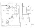
- FIG. 2is a block diagram of an apparatus and process in accordance with the present invention for compressing oxygen-enriched air and feeding it to a portable container;
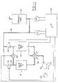
- FIG. 3is a block diagram of the apparatus and process of the present invention for feeding a portion of enriched gas at a controlled rate to a patient and another portion of the enriched gas to a compressor for high-pressure storage in a portable container;
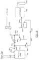
- FIG. 4is a block diagram of the apparatus and process of another embodiment of the present invention for feeding a portion of enriched gas at a controlled rate to a patient and another portion of the enriched gas to a compressor for high-pressure storage in a portable container;
- FIG. 5is a schematic showing one portion of a control circuit for operating a multiple-stage compressor of the present invention
- FIG. 6is a schematic of the remaining portion of the control circuit of FIG. 5 for operating a multiple-stage compressor of the present invention
- FIG. 7is a side elevational view of the compression apparatus of the present invention.
- FIG. 8is a top plan view of the compression apparatus of the present invention.
- FIG. 9is a side elevational view of the upper portion of the two-part piston assembly of the present invention.
- FIG. 10is a side elevational view of the bottom portion of the two-part piston assembly of the present invention.
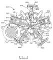
- FIG. 11is a top plan view of a radial compressor of the present invention.
- FIG. 12is a perspective view of the radial compressor of FIG. 11 showing inlet and outlet connections of the compression cylinders;
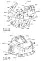
- FIG. 13is a perspective view of the portable high pressure oxygen conserving device of the present invention.
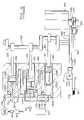
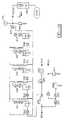
- FIG. 14is a mechanical and quasi-electrical schematic of the radial compressor and the flow system of the present invention.
- FIG. 15is a block diagram of the electrical circuitry of the invention including an oxygen concentration test mode aspect.
- the apparatusincludes one or more, and preferably two beds 10 and 12 which contain a physical separation medium or material.
- the separation materialselectively adsorbs one or more adsorbable components as from air and passes one or more nonadsorbable components of such a gaseous mixture.
- the physical separation materialcan be a molecular sieve with pores of uniform size and essentially the same molecular dimensions. These pores selectively adsorb molecules in accordance with molecular shape, polarity, degree of saturation, and the like.
- the physical separation mediumis an aluminasilicate composition with 4 to 5 A (Angstrom) pores.
- the molecular sieveis a sodium or calcium form of aluminasilicate, such as type 5A zeolite.
- the aluminasilicatemay have a higher silicon-to-aluminum ratio, larger pores, and an affinity for polar molecules, e.g., type 13x zeolite.
- the zeoliteadsorbs nitrogen, carbon monoxide, carbon dioxide, water vapor, and other significant components of air.
- a cross-over valving means 20which preferably includes a four-way valve 21 , selectively and cyclically connects the inlet end of two beds, one at a time, during a production phase with a source of the gas mixture, e.g., air under pressure supplied from a first compressor 22 (i.e., the feed compressor), while the other bed is vented to atmosphere during a purge phase.
- a source of the gas mixturee.g., air under pressure supplied from a first compressor 22 (i.e., the feed compressor)
- the cross-over valving meansselectively connects one of the beds in fluid communication with an air pump or compressor 22 which supplies air from about 15 to about 21 psi.
- fluid communicationrefers to means allowing flow of the appropriate gases.
- vacuumcan also be used during the purge phase with the present invention to enhance evacuation.
- Compressor 22which receives air from inlet 23 , is connected to a first drive motor 25 , in the preferred embodiment about a 1 ⁇ 4-horsepower electric motor.
- a solenoid (not shown) or other cross-over valve actuating meansselectively causes the cross-over valving means to move alternately between first and second positions.
- the first positionthe first bed 10 is connected with compressor 22 to cause nitrogen adsorption and oxygen enrichment in the product gas, and the second bed 12 is vented to atmosphere to allow evacuation.
- the first bedIn the second position, the first bed is vented to atmosphere to allow evacuation and the second bed is connected with the air compressor to cause nitrogen adsorption.
- the inventionis described with specific reference to a pressure-swing control. However, it is equally applicable to other methods of sequencing the gas flow through the sieve beds such as a timing-based system.
- the composition of the gas in the voids of the zeolitevaries from substantially pure primary-product gas at the outlet end, to the ambient gaseous mixture composition at the inlet end.
- an adsorption zone of finite, relatively large sizeis formed as the gas mixture is introduced through a bed inlet to an adsorbed, gas-free or regenerated bed.
- This adsorption zoneis a region of the bed in which the full capacity of the adsorbent to hold the adsorbable components has not been reached.
- This adsorption zonemoves from the bed inlet toward a bed outlet with a velocity significantly less than the superficial gas velocity in the bed.
- the breakthroughis defined by the size and configuration of the bed container as well as the packing configuration of the molecular sieve and the flow rate and bed gas pressure.
- the configuration of the bedis generally cylindrical and the output volume rate can vary from about 0.1 to 6 liters per minute.
- the breakthroughis the time required for the diffusion reaction as the nitrogen saturates and is weakly bonded to the sieve bed.
- primary product-enriched bed gas in the zeolite voidsvaries from a higher primary product gas concentration at the bed outlet to a lower concentration at the bed inlet.
- the primary product-enriched bed gasis about 80 percent primary product at breakthrough. While adsorption is occurring in one bed, the adsorbable components adsorbed by the separation medium of the other bed are purged from the other bed because of the drop in pressure due to atmospheric venting and because of exposure to relatively pure product gas from the first tank.
- the first bed 10is connected with a reservoir or product tank 30 by way of a first check valve 32 or other unidirectional valving means.
- the first check valve 32permits the primary product gas from the first bed 10 to flow into the reservoir or product tank 30 via line 46 when the product gas pressure in the first bed 10 exceeds the pressure of product gas in the reservoir or product tank 30 .
- the first check valveprohibits the product gas from flowing from the reservoir or product tank 30 when the pressure in the first bed 10 is lower than the reservoir or product tank. More specific to the preferred embodiment, the check valve imposes a 1.5 psi bias such that flow is only permitted when the pressure in the first bed exceeds the pressure in the reservoir or product tank by 1.5 psi.
- the second bed 12is connected with the reservoir or product tank 30 by way of a second check valve 34 or other unidirectional valving means. The second check valve 34 again provides for unidirectional flow of the primary product gas from the second bed 12 to the reservoir or product tank 30 .
- a pressure equalization flow path 40extends between outlets of the first and second beds.
- a concentration equalization valve 42is either open or closed to selectively permit or prevent gas flow through the flow path between the first and second beds.
- a control means 50cyclically causes the cross-over valve actuating means (i.e., two solenoids) and the concentration equalization valve 42 to be operated. The control means periodically and cyclically enables a concentration equalization valve actuator which is also a solenoid.
- Oxygen sensor 43registers the oxygen concentration of the product gas and can be located in the product tank 30 .
- the sensor 43communicates a sensed value to the microprocessor (i.e., control means).
- a pressure sensor 45registers the pressure in the product tank and communicates the same to the microprocessor.
- the control meanscauses the cross-over valving means 20 to alternate between its first and second positions for the appropriate period during each cycle segment.
- a cycle segmentcan be either the product gas generation cycle or the purge cycle.
- the cycle durationis selected such that each bed is connected with the source of air for a period of time which is equal to or less than the breakthrough time.
- the mechanism which triggers the cross-over valvingcan be based on the pressure, such as a pressure set point or set point range, in the bleed line from the product tank as is used in a pressure-based control cycle, or it can be based strictly on a residence time from the product-producing bed, such as in a timing cycle-based control cycle.
- control cyclecan utilize variable pressure in order to achieve a residence time within a defined range based upon a projected breakthrough time.
- the bedsare 3.5 inches in diameter, 15 inches in length, and each contains 6.5 pounds of 5A zeolite.
- the gas mixtureis supplied at up to 21 psi of pressure to the first bed.
- the second bedi.e., a “used” bed
- the second bedis vented to atmosphere to cause purging of the nitrogen-enriched molecular sieves.
- the concentration equalization valveis opened allowing primary product-enriched gas from the first bed to flow into the evacuated second bed.
- one bedis evacuated and the other has just reached the pressure set point which drives flow between the beds.
- the flowis of high oxygen content so that the first product to pass into the product tank via line 46 is essentially product gas produced by the oxygen beds.
- the second bed pressureis product-enriched gas to purge the sieve bed.
- the cross-over valving means 20is actuated to reverse its position. Actuating the cross-over valving means discontinues supplying of the gaseous mixture to the first bed and commences evacuating it and concurrently discontinues evacuating the second bed and commences supplying it with the gaseous mixture.
- the concentration equalization valve 42remains open to continue allowing a purge supply of product-enriched gas to flow into the second bed. This equalizes the concentration of gas which is supplied to the product tank since the cycling is sequenced so that the product gas proceeds from the breakthrough zone to flow into the product tank. Subsequently, the concentration equalization valve closes and terminates the flow of primary-product gas between the beds. In the second segment of the cycle, the pressure in the second bed increases approaching the gas mixture source pressure. Concurrently, the pressure in the first bed decreases approaching atmospheric pressure.
- the concentration equalization valve 42is opened allowing the primary product-enriched gas in the zeolite voids of the second bed to flow to the first bed. While the primary product-enriched gas is flowing to the first bed, the cross-over valving means is actuated. Actuating the cross-over valving means discontinues the evacuation of the first bed and commences supplying the gaseous mixture and concurrently discontinues supplying the gaseous mixture to the second bed and commences evacuating it. Subsequent to actuating the cross-over valving means, the concentration equalization valve is closed terminating the pressure equalizing flow of the primary product-enriched gas between the beds. The steps are cyclically repeated to provide continuing fractionating of the primary product gas from the mixture.
- the reservoir or product tank 30maintains a reservoir of oxygen at a minimum pressure of about 14 psi.
- the oxygen-enriched gascontains from about 50 to about 99 percent, desirably from about 70 to about 98 percent, and preferably from about 84 to about 96 percent by volume of oxygen.
- product tank 30can be connected to a pressure regulator (not shown) for controlling the pressure of the oxygen to a patient. Typically a pressure of 5 psi is utilized.
- a flow meteralso not shown in FIG. 1 ) can be utilized to limit the flow rate to the patient such as from 0.1 to about 6 liters per minute with a flow rate of about 3 liters per minute often being utilized.
- a humidifier(not shown) can add moisture to the oxygen-enriched gas.
- the gasis delivered to the patient via tubing and breathing apparatus which can be inserted into the patient's nostrils.
- oxygen-enriched gas from an oxygen concentratorsuch as that described hereinabove can be fed in any variety of methods to a compressor where it is compressed to very high pressure and stored in a portable or mobile container such as a gas cylinder.
- a concentrator(not shown but such as described hereinabove) has an oxygen-enriched product tank 30 wherein the pressure can vary as from about 14 to about 21 psi.
- the oxygen-enriched gas thereinis fed via line 201 to a flow meter 210 at the pressure of the concentrator tank, that is from about 14 to about 21 psi.
- Flow meter 210controls the flow rate of the oxygen-enriched gas which is fed via line 211 to buffer tank 220 wherein the gas pressure therein can also range from about 14 to about 21 psi.
- the predominantly oxygen gasis fed to compressor 100 .
- Compressor 100in a manner described below, compresses the oxygen-enriched gas to a pressure of about 2,250 psi and stores it within a mobile or portable cylinder 500 .
- the feed pressure theretocan range from 21 psi down to a predetermined cut-off pressure such as about 5 or 7 psi whereupon the compressor is automatically shut off by a pressure sensor switch.
- FIGS. 3 and 4relate to embodiments wherein oxygen-enriched air from product tank 30 of the oxygenator is fed by various methods desirably to a buffer tank of the compressor but prioritized as with regard to oxygen concentration and/or a sufficient pressure.
- the feed rate to a patientcan vary from between 0.1 and 6 liters per minute at a pressure of a predetermined value such as 5 psi with the remaining oxygen-enriched gas generally being fed at a different pressure to the buffer tank.
- the buffer tankcan generally contain a broad range of pressure therein such as, for example, between 14 and 21 psi.
- FIG. 3 and 4relate to embodiments wherein oxygen-enriched air from product tank 30 of the oxygenator is fed by various methods desirably to a buffer tank of the compressor but prioritized as with regard to oxygen concentration and/or a sufficient pressure.
- the feed rate to a patientcan vary from between 0.1 and 6 liters per minute at a pressure of a predetermined value such as 5 psi with the remaining oxygen-enriched gas generally
- the pressure thereofcan drop down to a predetermined cut-off pressure, such as 7 psi, which is higher than the pressure of the gas being fed to the patient to ensure an adequate flow of the oxygen-enriched gas to the patient.
- a 5-psi regulator 210emits oxygen-enriched gas from product tank 30 into flow line 220 and feeds the same to flow meter 230 which subsequently emits the oxygen-enriched gas to the patient at a predetermined flow rate of from 0.1 to 6 liters per minute.
- the flow metercan be closed so that all the enriched oxygen is directed to the compressor.
- Gas not directed to the patientis carried via line 240 to two-way valve 250 .
- a very small portion of the gas in line 220is directed through line 260 through restrictor 262 into oxygen sensor 265 which detects whether or not the concentration of the oxygen is of a predetermined value such as is at least 84 percent.
- two-way valve 250When the oxygen sensor detects a concentration at or above the predetermined level, two-way valve 250 is open and permits the oxygen-enriched gas to flow through line 270 into buffer tank 200 wherein the pressure is essentially the same as the oxygen product tank pressure. However, should the oxygen sensor not detect a suitable oxygen concentration, two-way valve 250 is closed so that the oxygen concentrator can build up a sufficient oxygen concentration. This arrangement prioritizes the flow of oxygen-enriched gas so that the patient is assured of receiving a gas having a minimum oxygen concentration therein.
- Buffer tank 200can have a regulator 280 thereon generally set at 12 psi to admit the oxygen-enriched gas to the compressor when needed. Alternatively, the pressure regulator can be set at anywhere from about 13 to about 21 psi.
- Restrictor 290controls the flow rate of gas from the buffer tank to the compressor. Should the compressor drop the pressure in the buffer tank to below a predetermined value, a pressure sensor (not shown) will automatically cut off the flow of gas at a pressure above the pressure of the gas being fed to the patient. This prioritization assures that the patient receives priority with regard to oxygen-enriched gas.
- FIG. 4emits the oxygen-enriched gas through a 14 to about an 18-psi regulator 300 into flow line 305 having flow rate restrictor 307 .
- the flowis then split with a portion via line 310 going through 5-psi regulator 320 and into flow meter 330 which then directs the gas to the patient at a desired flow rate of generally from 0.1 to 6 liters per minute, although optionally the flow meter can be closed.
- the remaining portion of the gasis directed via line 340 to two-way valve 350 .
- a small portion of the gas going to the patientis diverted through line 365 through flow restrictor 367 to oxygen sensor 360 .
- the oxygen sensoris set at a predetermined value such as a concentration of 84 percent so that when the level is not achieved, two-way valve 350 is closed through electrical line 355 .
- a predetermined valuesuch as a concentration of 84 percent
- This aspectallows the amount of oxygen in the concentrator tank to be increased by the oxygenator unit. The same prioritizes the concentration of oxygen to ensure that the patient receives an amount of oxygen of at least the minimum predetermined value.
- the gasflows through two-way valve 350 into line 370 and into buffer tank 200 where it is stored generally at a pressure of about 14 to 18 psi.
- a relief valve 385which can be set at any desired value such as about 14 psi ensures that gas under sufficient pressure is being admitted to the buffer tank.
- the oxygen-enriched gasis admitted to the compressor via line 380 .
- a pressure sensor switch(not shown) can be set to a predetermined value (e.g., about 7 psi) to ensure or prioritize that a sufficient amount or flow of gas is being fed to the patient.
- the predetermined shut-off pressure of the compressoris always above the pressure of the gas being fed to the patient. The embodiment of FIG. 4 is preferred.
- FIGS. 2 , 3 , and 4generally constitutes a preferred embodiment of the present invention
- oxygen product tank 30need not be utilized.
- the oxygen-enriched air from an oxygen concentratorsuch as shown in FIG. 1
- the buffer tankvia the shown and described flow lines of the various embodiments such as set forth in FIGS. 2 , 3 , and 4 .
- the oxygen-enriched airwill be separated with one component directed to the patient and the other component being directed to the buffer tank.
- Prioritization of the oxygen-enriched gas to the patient either by a minimum oxygen concentration or a sufficient pressure in the buffer tankis still generally utilized.
- an enriched oxygen product tank 30can be utilized and the buffer tank can optionally be eliminated.
- enriched oxygen from the product tankcan be fed via one component to the patient and to a second component via the flow line shown to the compressor. In this situation, prioritization of the desired flow and oxygen concentration to the patient is maintained as described hereinabove with regard to either the level of oxygen concentration or an adequate pressure being admitted to the compressor.
- the compressor assembly 100As shown in FIGS. 7 and 8 , it generally utilizes an AC electric-drive motor 105 which can rotate at any desired speed, e.g., 1,700 rpm.
- Motor 105can contain a fan (not shown) either within the motor housing or immediately adjacent thereto to draw air through the motor to cool the same.
- Poweris conveyed from the motor through shaft 106 to drive wheel 107 .
- the drive wheelhas a plurality of grooves therein to receive a V-belt such as main drive belt 109 .
- Such beltsare generally reinforced with fiber and have a very long life.
- Main drive belt 109is connected to main gear 110 which contains a plurality of grooves 113 therein.
- peripheral grooves 113coincides with the grooves of drive wheel 107 and matingly engage a plurality of projections located on main drive belt 109 .
- Extending from main gear 110is an offset hub gear 114 which has a much smaller diameter than main gear 110 .
- Hub gear 114also has grooves 115 thereon to receive a secondary drive V-belt 122 .
- a second or secondary large gear 116has grooves on the periphery thereof which matingly engage the secondary drive V-belt 122 .
- Offset hub 114 through the secondary V-drive belt 122contacts and serves to drive secondary gear 116 which in turn is connected to crankshaft 130 .
- crankshaft 130is a desirably low speed such as approximately 50 rpm.
- Both drive belts 109 and 122desirably have a spring-loaded idler arm 125 and 127 , respectively, which applies a small amount of tension.
- the actual pull tension of the first beltcan be about 20 pounds, whereas the tension on the second belt can be about 100 pounds.
- the multi-stage compressor of the present inventioncan have any number of pistons, but in the present embodiment has three. As shown in FIG. 8 , two of the pistons, i.e., the first and third pistons, are located on the same crankshaft lobe, whereas the second piston is located on a different lobe offset 180° from the first and third pistons. The reason for this is that pistons one and three will be drawing in air when the second piston is being compressed and vice versa.
- a crankshaftcan be utilized which contains three lobes thereon, each offset from one another by approximately 110° to 130°, e.g., about 120°, so as to minimize the torque resistance applied to the motor during the compression stroke.
- the compressor of the present inventionhas three pistons, i.e., piston # 1 ( 131 ), piston # 2 ( 133 ), and piston # 3 ( 135 ). Each piston is contained within a separate cylinder and thus piston # 1 is contained within the first cylinder ( 132 ), the second piston is contained the second cylinder ( 134 ), and the third piston is contained within the third cylinder ( 136 ). While the diameter of the head 140 of the first piston is approximately equal to the diameter of the base portion of the piston as shown in FIGS. 8 and 9 , the diameter of the head of piston # 2 ( 133 ) is smaller than that of piston # 1 , and the diameter of the head of piston # 3 ( 135 ) is smaller than the diameter of piston # 2 ( 133 ).
- each piston 131 B, 133 B, and 135 Bis of the same size for reasons set forth hereinbelow.
- eachcontains an annular sleeve 134 S and 136 S on the inside of the cylinder wall the internal diameter of which is approximately equal to the external diameter of piston heads # 2 and # 3 respectively.
- the piston headhas two annular grooves or recesses therein, that is top piston annulus 141 and bottom annulus 144 .
- the top annuluscontains a U-shaped seal therein generally made out of a Teflon® alloy or other low-friction material.
- the sealcontains a coil tension spring 143 therein which forces the seal radially outward against the cylinder wall to prevent compressed air from leaking through the piston head between the piston and the cylinder wall.
- seal 142is U-shaped so that upon the build-up of pressure in the cylinder head, the compressed gas will communicate and enter into the seal and force the outer edge thereof radially outward against the cylinder wall.
- Piston head bottom annulus 144contains a flat or vertical glide ring 145 which extends around the annulus and is also radially forced outwardly by a coil tension spring 146 located therein.
- the bottom glide ring 145can be made out of a Teflon® alloy and serves as a piston glide ring.
- Connecting rod 148connects the piston head to piston base 150 .
- the piston bases of all three pistonsare the same diameter and accordingly engage a mating cylinder of essentially the same diameter.
- the piston basecontains an upper base annulus 151 and a lower base annulus 155 , both of which have a glide ring therein similar to if not identical to glide ring 145 of piston head annulus 144 .
- upper base annulus 151has a glide ring 152 therein which is forced radially outward by coil spring 153 .
- lower base annulus 155has a glide ring 156 therein which is radially forced out by coil spring 157 .
- Piston base 150contains bore 158 which extends laterally therethrough. Bore 158 receives wrist pin 159 .
- the wrist pin and coil springboth serve to maintain glide ring 156 in a radially outward position so as to bear against the cylinder wall.
- the two-part piston assembly of the present inventioncontains bottom connecting rod 160 as shown in FIG. 10 .
- the connecting rodcontains a top bore 161 through which wrist pin 159 extends.
- Bottom bore 163 of the connecting rodextends about and matingly engages an appropriate portion of the crankshaft.
- sealed portion 164 of the connecting rodcontains bearings therein.
- the net result of the two-part piston ring assembly of the present inventionis that bearing 164 of connecting rod 160 can freely rotate with the crankshaft in a rotary or circular motion whereas top bore 161 moves in only a linear or reciprocal motion allowing piston rod 148 with the piston head and base thereon to move only in a linear reciprocating direction. The same thus prevents lateral forces from being applied to the cylinder wall which often results in wear and can create an oval-shaped cylinder wall.
- the two-part piston ring assembly of the present inventionthus promotes long life of the piston and cylinder wall.
- each pistonserves to compress the gas admitted therein to a higher pressure
- a desirable aspect of the present inventionis that each subsequent piston head has a smaller area.
- piston # 1( 131 ) can have a diameter of approximately 13 ⁇ 4 inches
- piston # 2has a diameter of approximately 11 ⁇ 4 inches
- piston # 3can have a diameter of approximately 1 ⁇ 2 inch, which can be the diameter of essentially piston rod 148 .
- the increase in pressure from each stage or pistonis proportional to the others.
- the compression ratio of each pistoncan vary, but generally is the same. Although compression ratios of up to 10 can be utilized, the desirable pressure range is from approximately 6 to about 8.
- cooling line 182 from the first piston to the second pistoncan be in the form of an undulating path or the like and the same is true with regard to cooling line 184 between the second and third pistons.
- the operation of the compressor portion of the apparatusis as follows. Electric motor 105 which operates independently of the compressor feeding air to the molecular sieves in the oxygen concentrator portion of the apparatus, through drive belts 109 and 122 , rotates crankshaft 130 thereby causing piston # 1 , # 2 , and # 3 ( 131 , 133 , 135 ) to reciprocate and compress air in their respective chambers. More specifically, enriched oxygen gas from the compressor buffer tank is fed to the first piston.
- Piston 131contains an inlet check valve 172 , which permits air to enter the cylinder head space above the piston, and outlet check valve 173 , which permits the compressed gas to exit from the first piston.
- second piston 133has an inlet check valve 175 which permits the compressed air from piston # 1 to be drawn into the head space above piston 133 , but prevents it from being forced back into the first piston.
- Outlet check valve 176prevents the gas compressing the second piston from being drawn back into the piston once it has been expelled therefrom.
- Rupture disk 180is a safety feature designed to rupture at a pressure in excess of the desired storage pressure of the gas cylinder. Thus, in the present embodiment, such a pressure can be approximately 2,800 psi. Although not shown, rupture disks can also be provided in the flow lines from the exit of the first and second cylinders to prevent undue build-up in these lines.
- a pressure regulator 181serves to emit the oxygen-enriched gas at a pressure of about 5 psi to a patient via a flow meter (not shown) at any desired rate, such as from about 0.1 to about 6 liters per minute.
- the buffer tankcontains oxygen-enriched gas at a pressure of generally from about 7 or 14 psi to about 21 psi.
- the compressoris designed to commence compression generally when the pressure in the tank is generally at a maximum until it drops to a predetermined pressure, e.g., 7 or 8 psi.
- a predetermined pressuree.g. 7 or 8 psi.
- the pressureis electrically controlled by various switches, sensors, relays and the like.
- a master ON/OFF switchemits power to compressor motor 105 which in turn causes the crankshaft to rotate and compress air.
- Two pressure-sensitive switchesexist: a low pressure sensor which detects pressure below a predetermined value, e.g., 7 to 12 psi, and a high pressure sensor which detects pressure above 2,250 psi.
- a low pressure sensordetects pressure below the predetermined level, it will turn off motor 105 through a relay switch.
- the low pressure sensoris a solid-state relay. Should the relay fail, it will fail closed and allow the motor to continue to run. Accordingly, this relay switch is connected in series with the high pressure sensor mechanical relay switch which will shut the motor off when the pressure in the cylinder reaches approximately 2,250 psi.
- FIGS. 5 and 6show the electrical circuitry of the compressor. Power is fed to the compressor initially through the resettable breaker 600 and then to power switch 610 . When the power switch is pushed to the “ON” position, power passes to the motor start switch 620 , the start relay common contacts 630 , and also lights the power indicator 640 . When start switch is depressed, the start relay coil is energized which causes both switches of the relay to close.
- One of these closed switchespasses the power to high pressure switch 650 which is normally closed when the output pressure of the compressor is under 2,250 psi.
- the output of the high pressure switchis fed back to the start relay coil to keep the coil energized without the start switch being depressed, but will cut power to the coil when high pressure is reached. (This occurs when a tank has been filled.)
- the output of the high pressure switchis also connected to the common of low pressure switch 660 . While the input pressure from the concentrator is above the predetermined value, e.g., 7 psi, the low pressure switch is closed and the normally closed contact has power. This power signal is fed to the drive contact of the solid-state relay which, in turn, allows the solid-state output to be “turned on.”
- the output of the high-pressure switchis also connected to the run indicator 670 which then lights up.
- the second closed switch of the start relayis connected to the “input” of the solid-state relay.
- the solid-state relayWhen the solid-state relay is turned on by the signal from the low pressure switch, power is passed to motor 105 and its start capacitors through the solid-state output.
- a common lineis connected to the other side of the motor to complete the circuit.
- An hour meter 690is wired in parallel to the motor to monitor motor run time.
- the motorbeings to run and remains running until one of two conditions occur.
- the first conditionwould be the input pressure to the compressor falls below a predetermined value, e.g., 7 psi. This will cause low pressure switch 660 to open and solid-state relay 695 to turn off, which in turn shuts off motor 105 . If the input pressure to the compressor rises above a desired predetermined pressure, low pressure switch 660 will close and once again turn on the solid-state relay and start the motor. This is a normal occurrence that is dependent upon concentrator efficiency and may be repetitive.
- the second condition that will shut off the motoroccurs when an oxygen tank has been filled.
- the output pressurewill rise above 2,250 psi and therefore cause high pressure switch 650 to open.
- Thiscuts the power to the start relay coil which causes both switches to open and cuts the power to both the input of the high pressure switch and the input to the solid-state relay thereby shutting off the motor.
- To start the motor after this condition is reachedrequires start switch 620 to be depressed. If greater than 2,250 psi remains, the high pressure switch will remain open and no signal will be fed back to the start relay coil to keep it energized therefore causing the motor to remain off. While the high pressure switch is open, run indicator 670 remains off.
- compressor 100is completely independent of the oxygen concentrator as well as utilization of gas compressed thereby as a power or energy source for the compressor.
- the pressure accumulated in the oxygen concentratoris not utilized to drive or operate a pressure intensifier.
- a distinct advantage of the apparatus and method for forming oxygen-enriched gas and compression thereof according to the present inventionis the creation of a mobile or portable source of gas containing high purity oxygen.
- Patients who require oxygen-enriched gasas from about 80 to about 98 percent, are no longer confined to the vicinity of an oxygen concentrator as for example a bed, home, hospital, or a wheelchair. Rather, the patient can carry the mobile gas cylinder in any convenient manner, such as in a backpack, and thus can take trips via wheelchair, an automobile, and even planes and trains.
- the oxygen supplycan be anywhere from about 2 to about 24 hours or even longer.
- a further embodiment of the present inventionrelates to an electromechanical oxygen distribution device or system as for use in a home to supply a patient with concentrated oxygen and also to concurrently supply pressurized and concentrated oxygen to a storage cylinder as for a patient's personal ambulatory use.
- the deviceis designed to be utilized in association with an oxygen source capable of supplying oxygen at a preferred concentration of at least 85% or 90% by volume at various pressures such as generally from about 2 to about 20 psig, and desirably from about 2.5 or about 4 to about 10 psig.
- Sources of concentrated oxygeninclude an oxygen concentrator as set forth herein above, or, conventional or commercially available oxygen concentrators, such as for example, but not limited to, Mallinckrodt-Aeris 590; Russ Products—Millienum; Sunrise; and the like.
- oxygen concentratorscan have various oxygen concentration outputs, pressures, and a desirable flow rates such as at least about 3, 5 or 6 liters per minute.
- the oxygen distribution system or device 800has housing 810 as well as oxygen test mode inlet 815 , oxygen normal operation inlet 820 for receiving oxygen from a concentrated oxygen source, oxygen outlet 825 for feeding oxygen to a patient, oxygen flow meter 830 for regulating the flow of oxygen to a patient, pressure gauge 835 , power switch 840 for turning the compressor unit or device on and off, and fill connector 845 for connecting the compressed gas to gas storage cylinder 1000 .
- the radial compressorgenerally utilizes an AC electric drive motor 905 which can rotate at any desired speed, such as generally from about 500 or 1,000 to about 3,600 or 6,000 RPM, and preferably from about 1,100 to about 1,300 RPM.
- the drive motorcan be of any horsepower and is desirably from about 1/100 to about 1 ⁇ 2 horsepower, with 1/12 horsepower most preferred.
- Drive motor 905can contain a fan (not shown) within the motor housing or immediately adjacent thereto to draw air through the motor thereby cooling the same.
- Drive belt 909is connected to compressor pulley 910 which has a plurality of grooves and/or teeth therein.
- an idler arm(not shown) can be utilized to keep tension on the drive belt.
- Compressor pulley 910is connected to crankshaft 911 .
- the radial multi-stage compressor of the present inventioncan have any number of pistons, such as from 2 to about 12, desirably from about 3 to about 8 or 10, with about 5 being preferred.
- the preferred embodimentcontains 5 pistons 915 , 916 , 917 , 918 , and 919 , that is the first through fifth pistons respectively, radially arranged around crankshaft 911 .
- Each pistonis located within separate cylinders 925 , 926 , 927 , 928 , and 929 with first piston 915 located in first cylinder 925 , etc.
- first piston 915 and second piston 916have a top and base which are integrally formed from a single element, and generally have the same diameter.
- the third piston 917 , fourth piston 918 , and fifth piston 919each have top portions which are smaller than the base portions thereof.
- each subsequent pistonis located on essentially the opposite side of the housing, the forces exerted on the various pistons by the crankshaft and the expanding air in the cylinders are generally balanced and result in the efficient transfer of energy.
- the radial designresults in a lightweight housing, which can be made of aluminum.
- the radial compressoris designed so that the volume of gas is reduced, desirably proportionally, in each succeeding piston/cylinder assembly.
- the compressible area 935 of the first piston/cylinder assemblyis larger than the compressible area 936 of the second piston/cylinder assembly, and so on.
- the compression ratiocan generally range from about 1 to about 10, and is preferably from about 2 to about 5, with about 2.5 being most preferred.
- Motor 905drives annular crankshaft 911 which drives master connecting rod 920 , as well as slave connecting rods 921 through 924 each operably connected thereto.
- the crankshafthas an offset thereon to allow reciprocation of the pistons.
- the operation of the radial compressorgenerally is as follows: Drive motor 905 through, drive belt 909 , and pulley 910 rotates crankshaft 911 and thus operably causes first through fifth pistons 915 – 919 to reciprocate and compress a source gas in their respective chambers. More specifically, a gas, which is preferably enriched oxygen gas is fed to the first piston 915 .
- the gases which are fed or supplied to the radial compressorcan be supplied from various sources, herein incorporated by reference, such as molecular sieve oxygen concentrator, a product tank or a buffer tank.
- gases from liquid or a high pressure oxygen cylinderwhich is typically too large and heavy to be easily moved, can serve as a source gas which is fed to the compressor.
- These large cylinderscontain a wide range of oxygen therein, such as typically from about 800 to about 900 cubic feet of compressed or liquified oxygen therein.
- each cylinder headcontains conventional check valve members such as ball and spring assemblies such as those set forth in FIG. 8 which permit a gas to flow in and out of the piston/cylinder assembly in a desired fashion, i.e. one direction.
- the preferred check valve member of the present embodimenthas a spring rated preferably at 2 psi or less.
- each cylinder head assemblywill contain two outlet check valves located sequentially with respect to one another as diagramically shown in FIG. 14 .
- FIGS. 11 and 12show various fittings and piston head assemblies containing check valves.
- Inlet check valve 940 of the first piston assemblypermits the gas to enter first compressible area 935 and outlet check valves 941 permits the compressed gas to exit the first piston.
- the check valvespermit the flow of gas in one direction so that once the gas is admitted to the first piston, it cannot be forced back out through the inlet check valve during the compression stroke of the piston.
- outlet check valves 941prevents gas form being sucked in during the intake stroke of the first piston.
- second piston 916has an inlet check valve 942 which permits the compressed gas from the first piston/cylinder assembly to be drawn into the second compressible area 936 , but prevents it from being forced back into the first piston.
- Outlet check valves 943prevents the gas compressed in the second piston/cylinder assembly from being drawn back into the same once it has been expelled therefrom.
- third piston 917has an inlet check valve 944 which permits the compressed gas from the second piston/cylinder assembly to be drawn into the third compressible area 937 , but prevents it from being forced back into the second piston.
- Outlet check valves 945prevents the gas compressed in the third piston/cylinder assembly from being drawn back into the same once it has been expelled therefrom.
- fourth piston 918has an inlet check valve 946 which permits the compressed gas from the third piston/cylinder assembly to be drawn into the fourth compressible area 938 , but prevents it from being forced back into the third piston.
- Outlet check valves 947prevents the gas compressed in the fourth piston/cylinder assembly from being drawn back into the same once it has been expelled therefrom.
- fifth piston 919has an inlet check valve 948 which permits the compressed gas from the fourth piston/cylinder assembly to be drawn into the fifth compressible area 939 , but prevents it from being forced back into the fourth piston.
- Outlet check valves 949prevents the gas compressed in the fifth piston/cylinder assembly from being drawn back into the same once it has been expelled therefrom.
- appropriate tubing able to withstand high pressuressuch as metal tubing, connects various parts of the oxygen distribution device such as the various piston/cylinder assemblies, the buffer tank, the various regulators, the storage cylinder, etc., in a conventional manner known to those skilled in the art.
- each sequential piston cylinder assemblyis not located adjacent to the next higher pressurizing piston cylinder assembly in a circumferential direction around the compressor, but is staggered or offset from one another by at least one piston cylinder assembly so as to balance the forces on the compressor and the crankshaft.
- each succeeding piston cylinder assembly with respect to increasing the pressure of the enriched oxygen from the previous assemblyis located at least two assembly positions away in a circumferential direction so that there is desirably at least one intervening piston cylinder assembly between each set or pair of sequentially or succeeding pressure piston cylinder assemblies.
- the first cylinderwill gradually build up a pressure, with the second cylinder gradually building up a higher pressure, etc. until a desirable pressure is reached in storage cylinder 1000 .
- the desired range from the concentrator or other oxygen sourceas from about 2 to about 20 psig is approximately 34 psig.
- the second compressorwill gradually build up to a pressure of approximately 110 psig with a third compressor gradually building up to a pressure of approximately 300 psig.
- the fourth compressorwill gradually build up to a maximum pressure of about 800 psig whereas the last or fifth compressor will build up to a maximum pressure of approximately 2,000 psig.
- cylinder 1000can accept pressures in a range generally from about 500 to about 4,000 psig, desirably from about 1,500 psig to about 3,000 psig, and preferably from about 1,900 psig to about 2,100 psig.
- the compressed gasis then fed through connector check valve 950 into a gas storage cylinder 1000 through appropriate tubing, connectors, valves, and the like.
- These storage cylinderscan generally be of any conventional size with standard sizes such as M6, C, D, and E, being suitable.
- the gas cylindercan hold a volume of compressed gas in a range generally from about 10 to about 650, desirably from about 50 or 100 to about 400 or 500, and preferably from about 150 to about 250 liters.
- the cylinderhas a built in pressure gauge of from about 0 to about 3,000 psig, and is equipped with a self-contained release valve as well as a high pressure rupture disk set for any desirable pressure such as about 6,000 psig. It can also have a hose barb outlet for connection to a patient cannula.
- the radial compressor 900can be substituted directly for compressor assembly 100 , that is in association with an oxygen concentrator, and with various flow schemes, designs, etc., whether preferably prioritized to insure that a patient receives a required amount of oxygen enriched gas, or not prioritized. Accordingly, the flow diagram of FIG. 2 , 3 , or 4 can be utilized but it is to be understood that generally any other flow system can also be utilized to route the enriched oxygen from product tank 30 either directly or indirectly, etc., to radial compressor 900 .
- the oxygen distribution system or device of the present invention containing the radial compressoris diagrammically shown in FIG. 14 .
- the oxygen distribution devicegenerally comprises oxygen sensor 860 , reservoir or buffer tank 875 , to accumulate or store the concentrated oxygen, the radial multi-stage compressor 900 , high pressure switch 880 , pressure gauge 835 , output oxygen fitting or connector 845 , portable high pressure cylinder 1000 . Also included is flow regulator 877 and flow meter 830 .
- the oxygen devicealso contains a test mode aspect, explained in greater detail hereinbelow, to determine at least the concentration of the oxygen from an oxygen concentrator, a large oxygen cylinder, or other source, before it is connected to the oxygen device.
- oxygen distribution device 800is assigned primarily for home use, it can also be used in other institutions such as nursing homes, clinics, hospital rooms, offices, and the like. As noted, the oxygen distribution device can receive various levels of concentration of oxygen such as at least about 50% or 75%, and desirably at least about 80%. However, with respect to the present invention, the oxygen device is generally designed to receive at least about 85%, and preferably at least about 90% oxygen and more preferably about 93% by volume plus or minus 3%.
- the oxygen sourcesuch as a concentrator is attached to oxygen inlet 820 . From there a small portion is fed to oxygen sensor 860 which continuously monitors the oxygen concentration. The remaining great majority of the oxygen is fed to a reservoir or buffer tank 875 whereafter it is channeled into two flow streams with a selected or predetermined portion of oxygen such as from about 1 to about 3, 4, or 5 and preferably about 2 liters per minute being fed to the compressor and with a selected or predetermined portion such as from about 0.1 to about 6, desirably from 1 to about 0.5 to about 5, and preferably from about 1 to about 3 liters per minute, flowing to a patient.
- a selected or predetermined portion of oxygensuch as from about 1 to about 3, 4, or 5 and preferably about 2 liters per minute
- a selected or predetermined portionsuch as from about 0.1 to about 6, desirably from 1 to about 0.5 to about 5, and preferably from about 1 to about 3 liters per minute, flowing to a patient.
- the oxygen distribution system of the present inventionis prioritized in that the radial compressor will only run when oxygen sensor 860 determines that the oxygen concentration is at or above a minimum predetermined level, for example 90% by volume. Thus, should the oxygen concentration drop below the predetermined level during operation of the compressor, sensor 960 will shut off the compressor until the concentration reaches the predetermined level. However, while the compressor is shutoff to build up the oxygen level, the enriched oxygen is continuously fed to the patient. As apparent from FIG.
- the enriched oxygen from the buffer tankpasses through pressure regulator 877 and flow meter 830 .
- Pressure regulator 877is set at any desired predetermined pressure level such as anywhere from about 1 to about 5 and desirably about 3 psig.
- the flow metercan be set by the patient, or by any other competent medical person such as a physical therapist, medical doctor, etc. to a desired flow rate.
- the oxygen being fed to the compressorgoes through a series of compression stages or cylinders with each subsequent stage pressurizing the gas to a higher pressure until finally the last stage achieves the desired indicated pressure whereupon cylinder pressure switch 880 will turn off compressor motor 905 .
- burst disk 884is provided to prevent an undue buildup of pressure within the storage cylinder.
- the only requirement required by the patient in operating the oxygen distribution device of the present inventionis to turn on power switch 840 and to set flow meter to desired rate as determined by a medical person or the like.
- the device 800may also advantageously include an oxygen concentration testing function.
- This test mode systemincludes the test mode inlet 815 .
- the inlet 815communicates with the oxygen sensor 860 through a check valve 854 whose downstream side is in communication with the downstream side of a check valve 872 that normally passes gas from the normal mode inlet 820 .
- the downstream sides of the check valves 854 , 872are both in communication with a flow restrictor 856 which limits the flow of gas to the oxygen sensor 860 .
- the check valve 872prevents the flow of gas from the test mode inlet 815 toward the normal mode inlet 820 .
- the check valve 854prevents the flow of gas from the normal mode inlet 820 toward the test mode inlet 815 .
- a test pressure switch 852senses the pressure of gas applied to the test mode inlet 815 .
- the switch 852provides an indication that pressurized gas is being applied to the test mode inlet 815 .
- the switch 852may, for example, be actuated by a gas pressure of 2.1 psi or greater.
- the compressor 900Upon indication of pressurized gas being applied to the test mode inlet 815 , the compressor 900 is disabled and the oxygen sensor 860 is then used to test the oxygen level or concentration of the gas applied to the test mode inlet 815 .
- the operation of the device 800may, for example, be advantageously controlled by a controller 1100 .
- the controller 1100is most preferably a microcontroller, but may be, for example, a microprocessor with associated memory and input/output circuitry, an application specific integrated circuit, a field programmable gate array, or other suitable programmable device.
- the controller 1100receives inputs from the oxygen sensor 860 , the high pressure switch 880 and the test pressure switch 852 and provides outputs to the compressor 900 and the indicators 1102 , 1104 , 1106 , 1108 , 1110 .
- the controller 1100may also, for example, incorporate the previously mentioned control means 50 .
- the indicators 1102 , 1104 , 1106 , 1108 , 1110may be, for example LEDs, light bulbs, an LCD screen, or other suitable indicators, including, for example, audible indicators.
- the FULL indicator a 1102 , the WAIT indicator 1104 , the FAULT indicator 1106 and the TEST indicator 1108will come on for a short time (e.g., 1 second) to provide an indication that these indicators are functioning. Then the indicators 1102 , 1106 , 1008 will go off.
- the WAIT indicator 1104will remain on long enough for the oxygen sensor 860 to reach operating temperature (e.g., 3.0 minutes).
- the controller 1100also monitors the heater current and voltage and the output current voltage of the oxygen sensor 860 whenever the device 800 is turned on. If a fault in the oxygen sensor 860 is detected at any time, the WAIT indicator 1104 is flashed at a one second rate, the FAULT indicator 1106 is activated and all other indicators are deactivated. In this state, the compressor 900 and the test mode function will not operate.
- the device 800will operate in normal mode. That is, if there is an acceptable level of oxygen as sensed by the oxygen sensor 860 in the gas applied to the normal mode inlet 820 (e.g., greater than 91 percent) the compressor 900 will run and the FILLING indicator 1110 will be activated. If the high pressure switch 880 is activated, the FULL indicator 1102 will be activated, the FILLING indicator 1110 will be deactivated and the compressor 900 will be deactivated by the controller 1100 .
- the FAULT indictor 1106will be flashed at a one second rate by the controller 1100 and the device 800 must be reset to operate.
- test pressure switch 852detects gas pressure at the test mode inlet 815 , the device 800 will operate in test mode. If the gas pressure at the inlet 815 is removed, the device 800 will again operate in normal mode.
- the controller 1100Whenever the device 800 enters or leaves test mode, the controller 1100 will suspend the operation of the device 1100 for a period of time (e.g., 30 seconds) and activate the WAIT indicator 1104 to allow the oxygen sensor 860 time to stabilize with a new input gas.
- a period of timee.g. 30 seconds
- the controller 1100will disable the compressor 900 , activate the TEST indicator 1108 and use the oxygen sensor 860 to test the oxygen level of the gas applied to the test mode inlet 815 . If there is an acceptable level of oxygen, the controller 1100 will activate the FULL indicator 1102 . Otherwise, the controller 1100 will activate the FAULT indicator 1106 .
- the test mode of operationpermits a user to conveniently check the oxygen content of a cylinder or concentrator output without activating the compressor of the device.
- the useractivates the test mode by merely connecting a gas source to the test mode inlet. Normal operation resumes when the gas source is removed.
- the useris not required to perform any other operation. This is particularly advantageous for impaired, unsophisticated or technology intimidated users.
- the radial compressor and assembly comprising connecting tubing etc.is compact and light, approximately 1 ⁇ 4 the size of compressor assembly 100 shown in FIG. 8 , and approximately 1 ⁇ 4 the weight thereof.
- the radial compressor of the present inventioncan be utilized with any commercially available oxygen concentrator and has a unitized construction and compact design for easy placement and storage.
- the radial compressor of the present inventionis very efficient with respect to power consumption, is quiet when running, and produces very little vibration.
- the unithas generally the same features as other units such as in FIGS. 1–10 , for example, the same fill time.
Landscapes
- Health & Medical Sciences (AREA)
- Engineering & Computer Science (AREA)
- Chemical & Material Sciences (AREA)
- Emergency Medicine (AREA)
- Biomedical Technology (AREA)
- Heart & Thoracic Surgery (AREA)
- Oil, Petroleum & Natural Gas (AREA)
- General Chemical & Material Sciences (AREA)
- Pulmonology (AREA)
- Anesthesiology (AREA)
- Analytical Chemistry (AREA)
- Chemical Kinetics & Catalysis (AREA)
- Hematology (AREA)
- Life Sciences & Earth Sciences (AREA)
- Animal Behavior & Ethology (AREA)
- General Health & Medical Sciences (AREA)
- Public Health (AREA)
- Veterinary Medicine (AREA)
- Separation Of Gases By Adsorption (AREA)
- Oxygen, Ozone, And Oxides In General (AREA)
Abstract
Description
Claims (18)
Priority Applications (22)
| Application Number | Priority Date | Filing Date | Title |
|---|---|---|---|
| US08/942,063US5988165A (en) | 1997-10-01 | 1997-10-01 | Apparatus and method for forming oxygen-enriched gas and compression thereof for high-pressure mobile storage utilization |
| DE69819469TDE69819469T2 (en) | 1997-10-01 | 1998-09-16 | Apparatus for compressing and storing oxygen-enriched gas |
| US09/154,442US6302107B1 (en) | 1997-10-01 | 1998-09-16 | Apparatus and method for forming oxygen-enriched gas and compression thereof for high-pressure mobile storage utilization |
| AU94880/98AAU715855B2 (en) | 1997-10-01 | 1998-09-16 | Apparatus and method for forming oxygen-enriched gas and compression thereof for high-pressure mobile storage utilization |
| PCT/US1998/019282WO1999016529A2 (en) | 1997-10-01 | 1998-09-16 | Apparatus and method for forming oxygen-enriched gas and compression thereof for high-pressure mobile storage utilization |
| CA002269555ACA2269555C (en) | 1997-10-01 | 1998-09-16 | Apparatus and method for forming oxygen-enriched gas and compression thereof for high-pressure mobile storage utilization |
| EP98948271AEP0948385B1 (en) | 1997-10-01 | 1998-09-16 | Apparatus for compressing and storing an oxygen-enriched gas |
| US09/695,612US7204249B1 (en) | 1997-10-01 | 2000-10-24 | Oxygen conserving device utilizing a radial multi-stage compressor for high-pressure mobile storage |
| US09/952,763US6805122B2 (en) | 1997-10-01 | 2001-09-14 | Oxygen conserving device utilizing a radial multi-stage compressor for high-pressure mobile storage |
| AT01988512TATE350134T1 (en) | 2000-10-24 | 2001-10-24 | DEVICE AND METHOD FOR SUPPLYING OXYGEN ENRICHED GAS |
| AU2002218003AAU2002218003B2 (en) | 2000-10-24 | 2001-10-24 | Apparatus and process for supplying oxygen-enriched gas |
| AU1800302AAU1800302A (en) | 1997-10-01 | 2001-10-24 | Apparatus and process for supplying oxygen-enriched gas |
| DE60125826TDE60125826T2 (en) | 2000-10-24 | 2001-10-24 | DEVICE AND METHOD FOR SUPPLYING OXYGENATED GAS |
| EP01988512AEP1345670B1 (en) | 1997-10-01 | 2001-10-24 | Apparatus and process for supplying oxygen-enriched gas |
| PCT/US2001/045433WO2002034368A1 (en) | 1997-10-01 | 2001-10-24 | Apparatus and process for supplying oxygen-enriched gas |
| HK04102110.7AHK1059236B (en) | 2000-10-24 | 2001-10-24 | Apparatus and process for supplying oxygen-enriched gas |
| CA2426685ACA2426685C (en) | 1997-10-01 | 2001-10-24 | Apparatus and process for supplying oxygen-enriched gas |
| PCT/US2002/029164WO2003024569A1 (en) | 1997-10-01 | 2002-09-13 | Apparatus and process for supplying oxygen-enriched gas |
| US10/605,754US6923180B2 (en) | 1997-10-01 | 2003-10-23 | Oxygen conserving device utilizing a radial multi-stage compressor for high-pressure mobile storage |
| US11/180,395US7294170B2 (en) | 1997-10-01 | 2005-07-13 | Apparatus for compressing and storing oxygen enriched gas |
| US11/938,551US8123497B2 (en) | 1997-10-01 | 2007-11-12 | Apparatus for compressing and storing oxygen enriched gas |
| US13/404,848US20120152248A1 (en) | 1997-10-01 | 2012-02-24 | Apparatus for compressing and storing oxygen enriched gas |
Applications Claiming Priority (3)
| Application Number | Priority Date | Filing Date | Title |
|---|---|---|---|
| US08/942,063US5988165A (en) | 1997-10-01 | 1997-10-01 | Apparatus and method for forming oxygen-enriched gas and compression thereof for high-pressure mobile storage utilization |
| US09/154,442US6302107B1 (en) | 1997-10-01 | 1998-09-16 | Apparatus and method for forming oxygen-enriched gas and compression thereof for high-pressure mobile storage utilization |
| US09/695,612US7204249B1 (en) | 1997-10-01 | 2000-10-24 | Oxygen conserving device utilizing a radial multi-stage compressor for high-pressure mobile storage |
Related Parent Applications (1)
| Application Number | Title | Priority Date | Filing Date |
|---|---|---|---|
| US09/154,442Continuation-In-PartUS6302107B1 (en) | 1997-10-01 | 1998-09-16 | Apparatus and method for forming oxygen-enriched gas and compression thereof for high-pressure mobile storage utilization |
Related Child Applications (1)
| Application Number | Title | Priority Date | Filing Date |
|---|---|---|---|
| US09/952,763Continuation-In-PartUS6805122B2 (en) | 1997-10-01 | 2001-09-14 | Oxygen conserving device utilizing a radial multi-stage compressor for high-pressure mobile storage |
Publications (1)
| Publication Number | Publication Date |
|---|---|
| US7204249B1true US7204249B1 (en) | 2007-04-17 |
Family
ID=37914034
Family Applications (1)
| Application Number | Title | Priority Date | Filing Date |
|---|---|---|---|
| US09/695,612Expired - Fee RelatedUS7204249B1 (en) | 1997-10-01 | 2000-10-24 | Oxygen conserving device utilizing a radial multi-stage compressor for high-pressure mobile storage |
Country Status (1)
| Country | Link |
|---|---|
| US (1) | US7204249B1 (en) |
Cited By (46)
| Publication number | Priority date | Publication date | Assignee | Title |
|---|---|---|---|---|
| US20050192538A1 (en)* | 2004-02-26 | 2005-09-01 | Voege James A. | Method and apparatus for regulating fluid flow or conserving fluid flow |
| US20070065301A1 (en)* | 2005-09-21 | 2007-03-22 | Gerold Goertzen | System and method for providing oxygen |
| US20080041376A1 (en)* | 2006-08-16 | 2008-02-21 | Rescue Air Systems, Inc. | Safety system and method of an underground mine |
| US20080041379A1 (en)* | 2006-08-16 | 2008-02-21 | Rescue Air Systems, Inc. | Breathable air safety system and method having at least one fill site |
| US20080041378A1 (en)* | 2006-08-16 | 2008-02-21 | Rescue Air Systems, Inc. | Breathable air safety system and method having an air storage sub-system |
| US20080041377A1 (en)* | 2006-08-16 | 2008-02-21 | Rescue Air Systems, Inc. | Safety system and method of a tunnel structure |
| US20080118373A1 (en)* | 1997-10-01 | 2008-05-22 | Invacare Corporation | Apparatus for compressing and storing oxygen enriched gas |
| US20080277399A1 (en)* | 2007-04-20 | 2008-11-13 | Ricky Dean Burns | System and Method for Filling a Portable Liquified Gas Storage/Delivery System |
| WO2009068059A1 (en)* | 2007-11-29 | 2009-06-04 | Airbus Operations Gmbh | Tester for testing operational reliability of a cockpit oxygen distribution circuit |
| US20090178675A1 (en)* | 2006-08-16 | 2009-07-16 | Turiello Anthony J | Breathable air safety system and method |
| US20090205493A1 (en)* | 2008-02-20 | 2009-08-20 | Thompson Loren M | Method of removing water from an inlet region of an oxygen generating system |
| US20090205494A1 (en)* | 2008-02-20 | 2009-08-20 | Mcclain Michael S | Single manifold assembly for oxygen-generating systems |
| US20090214393A1 (en)* | 2008-02-22 | 2009-08-27 | Chekal Michael P | Method of generating an oxygen-enriched gas for a user |
| US20090211443A1 (en)* | 2008-02-21 | 2009-08-27 | Youngblood James H | Self-serviceable filter for an oxygen generating device |
| US20090211438A1 (en)* | 2008-02-21 | 2009-08-27 | Thompson Loren M | Method of determining the purity of oxygen present in an oxygen-enriched gas produced from an oxygen delivery system |
| US20090229460A1 (en)* | 2008-03-13 | 2009-09-17 | Mcclain Michael S | System for generating an oxygen-enriched gas |
| US7617826B1 (en) | 2004-02-26 | 2009-11-17 | Ameriflo, Inc. | Conserver |
| US20090283151A1 (en)* | 2006-08-16 | 2009-11-19 | Rescue Air Systems, Inc. | Breathable air safety system and method having a fill station |
| USD606655S1 (en) | 2008-06-27 | 2009-12-22 | Inova Labs, Llc | Portable oxygen concentrator |
| US20110038740A1 (en)* | 2009-08-17 | 2011-02-17 | Invacare Corporation | Compressor |
| US20110103976A1 (en)* | 2008-03-10 | 2011-05-05 | Besim Fejzuli | Device and method for preparing liquefied natural gas (lng) fuel |
| US20110120461A1 (en)* | 2005-01-18 | 2011-05-26 | Respironics, Inc. | Trans-fill method and system |
| US8075676B2 (en) | 2008-02-22 | 2011-12-13 | Oxus America, Inc. | Damping apparatus for scroll compressors for oxygen-generating systems |
| US20120192864A1 (en)* | 2009-10-05 | 2012-08-02 | Separation Design Group Llc | Ultra Rapid Cycle Portable Oxygen Concentrator |
| US20130205999A1 (en)* | 2012-02-14 | 2013-08-15 | L'air Liquide, Societe Anonyme Pour L'etude Et L'exploitation Des Procedes Georges Claude | On-site medical gas production plant and associated operating method |
| US20130205997A1 (en)* | 2012-02-14 | 2013-08-15 | L'Air Liquide, Société Anonyme pour l'Etude et l'Exploitation des Procédés Georges Claude | Method for operating an on-site medical gas production plant and associated plant |
| US8603228B2 (en) | 2010-09-07 | 2013-12-10 | Inova Labs, Inc. | Power management systems and methods for use in an oxygen concentrator |
| US8616207B2 (en) | 2010-09-07 | 2013-12-31 | Inova Labs, Inc. | Oxygen concentrator heat management system and method |
| US8770199B2 (en) | 2012-12-04 | 2014-07-08 | Ino Therapeutics Llc | Cannula for minimizing dilution of dosing during nitric oxide delivery |
| US8794237B2 (en) | 2007-09-06 | 2014-08-05 | Inova Labs, Inc. | Oxygen concentrator apparatus and method having flow restricted coupling of the canisters |
| US20140216453A1 (en)* | 2011-09-13 | 2014-08-07 | Koninklijke Philips N.V. | Oxygen concentrator supply line oberpressure protection |
| WO2015148911A1 (en)* | 2014-03-28 | 2015-10-01 | Caire Inc. | Controlling oxygen concentrator timing cycle based on flow rate of oxygen output |
| US9440179B2 (en) | 2014-02-14 | 2016-09-13 | InovaLabs, LLC | Oxygen concentrator pump systems and methods |
| US9440036B2 (en) | 2012-10-12 | 2016-09-13 | InovaLabs, LLC | Method and systems for the delivery of oxygen enriched gas |
| US9440180B2 (en) | 2012-10-12 | 2016-09-13 | Inova Labs, Llc | Oxygen concentrator systems and methods |
| WO2016164880A1 (en)* | 2015-04-10 | 2016-10-13 | Scott Technologies, Inc. | System and method for controlling moisture within an air compressor assembly |
| US9624918B2 (en) | 2012-02-03 | 2017-04-18 | Invacare Corporation | Pumping device |
| US9682210B2 (en) | 2013-09-27 | 2017-06-20 | L'Air Liquide, Société Anonyme pour l'Etude et l'Exploitation des Procédés Georges Claude | On-site medical gas production plant and associated operating method |
| US9694151B2 (en) | 2013-09-27 | 2017-07-04 | L'Air Liquide, Société Anonyme pour l'Etude et l'Exploitation des Procédés Georges Claude | On-site medical gas production plant and associated operating method |
| US9717876B2 (en) | 2012-10-12 | 2017-08-01 | Inova Labs, Inc. | Dual oxygen concentrator systems and methods |
| US9795756B2 (en) | 2012-12-04 | 2017-10-24 | Mallinckrodt Hospital Products IP Limited | Cannula for minimizing dilution of dosing during nitric oxide delivery |
| CN108862193A (en)* | 2018-08-15 | 2018-11-23 | 黑龙江莱睿普思环境科技发展有限公司 | A kind of pressure surge tank for methanol decomposition hydrogen manufacturing |
| US10307317B2 (en) | 2014-09-11 | 2019-06-04 | Vitalaire Canada Inc. | On-site medical gas production plant and associated operating method |
| US20220105288A1 (en)* | 2020-10-05 | 2022-04-07 | Zoll Medical Corporation | Respiratory distress management apparatus, system and method |
| US11458274B2 (en) | 2016-05-03 | 2022-10-04 | Inova Labs, Inc. | Method and systems for the delivery of oxygen enriched gas |
| US20220313938A1 (en)* | 2021-03-31 | 2022-10-06 | Inogen, Inc. | Systems and methods for mitigating noise and vibration in a portable oxygen concentrator |
Citations (75)
| Publication number | Priority date | Publication date | Assignee | Title |
|---|---|---|---|---|
| GB374540A (en) | 1930-03-19 | 1932-06-16 | Michele Antonio Caserta | Improvement in air or gas compressors |
| US2944627A (en) | 1958-02-12 | 1960-07-12 | Exxon Research Engineering Co | Method and apparatus for fractionating gaseous mixtures by adsorption |
| US3313091A (en) | 1963-11-04 | 1967-04-11 | Exxon Research Engineering Co | Vacuum cycle adsorption |
| US3898047A (en) | 1973-07-17 | 1975-08-05 | Bendix Corp | Oxygen generation system |
| US3924968A (en)* | 1972-07-27 | 1975-12-09 | Gen Motors Corp | Radial compressor with muffled gas chambers and short stable piston skirts and method of assembling same |
| US3964866A (en) | 1974-09-13 | 1976-06-22 | William Barney Shelby | Helium reclamation |
| US4013429A (en) | 1975-06-04 | 1977-03-22 | Air Products And Chemicals, Inc. | Fractionation of air by adsorption |
| US4194890A (en) | 1976-11-26 | 1980-03-25 | Greene & Kellogg, Inc. | Pressure swing adsorption process and system for gas separation |
| US4222750A (en) | 1976-08-16 | 1980-09-16 | Champion Spark Plug Company | Oxygen enrichment system for medical use |
| US4263018A (en) | 1978-02-01 | 1981-04-21 | Greene & Kellogg | Pressure swing adsorption process and system for gas separation |
| US4331455A (en) | 1979-05-11 | 1982-05-25 | Osaka Oxygen Industries, Ltd. | Method of producing oxygen rich gas utilizing an oxygen concentrator having good start-up characteristics |
| US4349357A (en) | 1980-06-23 | 1982-09-14 | Stanley Aviation Corporation | Apparatus and method for fractionating air and other gaseous mixtures |
| US4353682A (en)* | 1980-09-22 | 1982-10-12 | The Trane Company | Reciprocating gas compressor having suction shut-off unloading means |
| WO1983003983A1 (en) | 1982-05-07 | 1983-11-24 | Marathon Medical Equipment Corporation | Oxygen concentrator |
| US4428372A (en)* | 1980-07-31 | 1984-01-31 | Linde Aktiengesellschaft | Process and apparatus for providing breathing gas |
| US4449990A (en) | 1982-09-10 | 1984-05-22 | Invacare Respiratory Corp. | Method and apparatus for fractioning oxygen |
| US4465436A (en)* | 1981-05-25 | 1984-08-14 | Siemens Aktiengesellschaft | Radial piston compressor |
| US4516424A (en) | 1982-07-09 | 1985-05-14 | Hudson Oxygen Therapy Sales Company | Oxygen concentrator monitor and regulation assembly |
| US4552571A (en)* | 1984-04-05 | 1985-11-12 | Vbm Corporation | Oxygen generator with two compressor stages |
| US4576616A (en) | 1982-07-27 | 1986-03-18 | Proto-Med. Inc. | Method and apparatus for concentrating oxygen |
| US4610700A (en) | 1983-11-04 | 1986-09-09 | Union Carbide Corporation | Adsorbent composition useful in retarding corrosion in mufflers |
| US4627860A (en) | 1982-07-09 | 1986-12-09 | Hudson Oxygen Therapy Sales Company | Oxygen concentrator and test apparatus |
| US4636226A (en) | 1985-08-26 | 1987-01-13 | Vbm Corporation | High pressure oxygen production system |
| WO1987001599A1 (en)* | 1985-09-23 | 1987-03-26 | Battelle Development Corporation | Oxygen/air mixture blower for respiratory care |
| US4670223A (en) | 1983-01-26 | 1987-06-02 | Le Masne S.A. | Apparatus for producing sterile air for medical use |
| US4673415A (en) | 1986-05-22 | 1987-06-16 | Vbm Corporation | Oxygen production system with two stage oxygen pressurization |
| US4698075A (en) | 1986-06-05 | 1987-10-06 | International Oxygen Company, Inc. | Control system for fluid absorption systems and the like |
| EP0239713A1 (en) | 1986-04-02 | 1987-10-07 | VOEST-ALPINE Aktiengesellschaft | Process for purifying gases and device for performing the process |
| US4706664A (en) | 1986-04-11 | 1987-11-17 | Puritan-Bennett Corporation | Inspiration oxygen saver |
| US4765804A (en) | 1986-10-01 | 1988-08-23 | The Boc Group, Inc. | PSA process and apparatus employing gaseous diffusion barriers |
| JPS63307101A (en) | 1987-06-05 | 1988-12-14 | Kobe Steel Ltd | Pressure swing adsorption type production of oxygen |
| JPS6428208U (en) | 1987-08-10 | 1989-02-20 | ||
| US4844059A (en) | 1986-01-22 | 1989-07-04 | Draegerwerk Ag | Method and apparatus for enriching respiratory gas with oxygen and delivering it to a patient |
| US4860803A (en) | 1988-09-15 | 1989-08-29 | The United States Of America As Represented By The Department Of Commerce | Continuous nitrox mixer |
| US4867766A (en) | 1988-09-12 | 1989-09-19 | Union Carbide Corporation | Oxygen enriched air system |
| US4869733A (en) | 1986-05-22 | 1989-09-26 | Vbm Corporation | Super-enriched oxygen generator |
| US4880443A (en) | 1988-12-22 | 1989-11-14 | The United States Of America As Represented By The Secretary Of The Air Force | Molecular sieve oxygen concentrator with secondary oxygen purifier |
| US4905685A (en) | 1987-04-14 | 1990-03-06 | Siemens Aktiengesellschaft | Inhalation anaesthesia equipment |
| US4922900A (en) | 1988-05-19 | 1990-05-08 | Dragerwerk Aktiengesellschaft | Pumping arrangement for supplying a ventilating apparatus with breathing gas |
| US4948391A (en) | 1988-05-12 | 1990-08-14 | Vacuum Optics Corporation Of Japan | Pressure swing adsorption process for gas separation |
| US4957107A (en)* | 1988-05-10 | 1990-09-18 | Sipin Anatole J | Gas delivery means |
| US4979882A (en)* | 1989-03-13 | 1990-12-25 | Wisconsin Alumni Research Foundation | Spherical rotary machine having six rotary pistons |
| US4983190A (en) | 1985-05-21 | 1991-01-08 | Pall Corporation | Pressure-swing adsorption system and method for NBC collective protection |
| US4991616A (en) | 1988-01-11 | 1991-02-12 | Desarrollos, Estudios Y Patentes, S.A. | Installation for the supply of oxygen in hospitals and the like |
| US5071453A (en) | 1989-09-28 | 1991-12-10 | Litton Systems, Inc. | Oxygen concentrator with pressure booster and oxygen concentration monitoring |
| US5078757A (en) | 1989-05-24 | 1992-01-07 | L'air Liquide, Societe Anonyme Pour L'etude Et L'exploitation Des Procedes Georges Claude | Process for the production of gaseous oxygen under pressure |
| US5144945A (en)* | 1989-04-20 | 1992-09-08 | Nippon Sanso Kabushiki Kaisha | Portable oxygen-enriching air inhaler |
| US5154737A (en) | 1990-01-12 | 1992-10-13 | Vbm Corporation | System for eliminating air leakage and high purity oxygen of a PSA oxygen concentrator |
| US5163978A (en) | 1991-10-08 | 1992-11-17 | Praxair Technology, Inc. | Dual product pressure swing adsorption process and system |
| US5195874A (en)* | 1990-06-19 | 1993-03-23 | Tokico Ltd. | Multistage compressor |
| US5199423A (en) | 1990-02-10 | 1993-04-06 | Normalair-Garrett (Holdings) Ltd. | Oxygen-rich gas breathing systems for passenger carrying aircraft |
| US5207806A (en) | 1991-10-08 | 1993-05-04 | Praxair Technology, Inc. | Dual product pressure swing adsorption and membrane operations |
| US5237987A (en) | 1990-06-07 | 1993-08-24 | Infrasonics, Inc. | Human lung ventilator system |
| US5248320A (en) | 1991-11-11 | 1993-09-28 | The Boc Group Plc | Compressing oxygen |
| US5354361A (en) | 1993-05-28 | 1994-10-11 | Litton Industries, Inc. | Energy recovering pressure balance scheme for a combination pressure swing absorber with a boost compressor |
| US5405249A (en) | 1992-11-11 | 1995-04-11 | Ultra Electronics Limited | Gas supply apparatus |
| US5474595A (en) | 1994-04-25 | 1995-12-12 | Airsep Corporation | Capacity control system for pressure swing adsorption apparatus and associated method |
| US5490871A (en) | 1993-01-30 | 1996-02-13 | The Boc Group Plc | Gas separation |
| US5531807A (en) | 1994-11-30 | 1996-07-02 | Airsep Corporation | Apparatus and method for supplying oxygen to passengers on board aircraft |
| US5584669A (en) | 1993-04-15 | 1996-12-17 | Knf Neuberger Gmbh | Two-stage positive displacement pump |
| US5593478A (en) | 1994-09-28 | 1997-01-14 | Sequal Technologies, Inc. | Fluid fractionator |
| US5593291A (en) | 1995-07-25 | 1997-01-14 | Thomas Industries Inc. | Fluid pumping apparatus |
| US5704964A (en) | 1994-12-27 | 1998-01-06 | Nippon Sanso Corporation | Pressure swing adsorption process |
| EP0860647A2 (en) | 1997-02-10 | 1998-08-26 | Litton Systems, Inc. | Integrated high pressure fill port and flow controller for cylinder recharger |
| US5823186A (en)* | 1996-06-20 | 1998-10-20 | Dragerwerk Ag | Respirator |
| US5858062A (en) | 1997-02-10 | 1999-01-12 | Litton Systems, Inc. | Oxygen concentrator |
| US5875783A (en)* | 1997-04-09 | 1999-03-02 | Dragerwerk Ag | Gas delivery means for respirators and anesthesia apparatus |
| WO1999016529A2 (en) | 1997-10-01 | 1999-04-08 | Invacare Corporation | Apparatus and method for forming oxygen-enriched gas and compression thereof for high-pressure mobile storage utilization |
| US5893944A (en) | 1997-09-30 | 1999-04-13 | Dong; Jung Hyi | Portable PSA oxygen generator |
| US5893275A (en) | 1997-09-04 | 1999-04-13 | In-X Corporation | Compact small volume liquid oxygen production system |
| US6132177A (en)* | 1997-08-14 | 2000-10-17 | Bristol Compressors, Inc. | Two stage reciprocating compressors and associated HVAC systems and methods |
| US6393802B1 (en)* | 1999-12-22 | 2002-05-28 | Sunrise Medical Hhg, Inc. | Cylinder filler for use with an oxygen concentrator |
| US6422237B1 (en)* | 1999-05-18 | 2002-07-23 | DRäGER MEDIZINTECHNIK GMBH | Respirator with a breathing circuit |
| US6478857B2 (en)* | 1999-05-12 | 2002-11-12 | Respironics, Inc. | Total delivery oxygen concentration system |
| US6651658B1 (en) | 2000-08-03 | 2003-11-25 | Sequal Technologies, Inc. | Portable oxygen concentration system and method of using the same |
- 2000
- 2000-10-24USUS09/695,612patent/US7204249B1/ennot_activeExpired - Fee Related
Patent Citations (81)
| Publication number | Priority date | Publication date | Assignee | Title |
|---|---|---|---|---|
| GB374540A (en) | 1930-03-19 | 1932-06-16 | Michele Antonio Caserta | Improvement in air or gas compressors |
| US2944627A (en) | 1958-02-12 | 1960-07-12 | Exxon Research Engineering Co | Method and apparatus for fractionating gaseous mixtures by adsorption |
| US3313091A (en) | 1963-11-04 | 1967-04-11 | Exxon Research Engineering Co | Vacuum cycle adsorption |
| US3924968A (en)* | 1972-07-27 | 1975-12-09 | Gen Motors Corp | Radial compressor with muffled gas chambers and short stable piston skirts and method of assembling same |
| US3898047A (en) | 1973-07-17 | 1975-08-05 | Bendix Corp | Oxygen generation system |
| US3964866A (en) | 1974-09-13 | 1976-06-22 | William Barney Shelby | Helium reclamation |
| US4013429A (en) | 1975-06-04 | 1977-03-22 | Air Products And Chemicals, Inc. | Fractionation of air by adsorption |
| US4222750A (en) | 1976-08-16 | 1980-09-16 | Champion Spark Plug Company | Oxygen enrichment system for medical use |
| US4194890A (en) | 1976-11-26 | 1980-03-25 | Greene & Kellogg, Inc. | Pressure swing adsorption process and system for gas separation |
| US4263018A (en) | 1978-02-01 | 1981-04-21 | Greene & Kellogg | Pressure swing adsorption process and system for gas separation |
| US4331455A (en) | 1979-05-11 | 1982-05-25 | Osaka Oxygen Industries, Ltd. | Method of producing oxygen rich gas utilizing an oxygen concentrator having good start-up characteristics |
| US4349357A (en) | 1980-06-23 | 1982-09-14 | Stanley Aviation Corporation | Apparatus and method for fractionating air and other gaseous mixtures |
| US4428372A (en)* | 1980-07-31 | 1984-01-31 | Linde Aktiengesellschaft | Process and apparatus for providing breathing gas |
| US4353682A (en)* | 1980-09-22 | 1982-10-12 | The Trane Company | Reciprocating gas compressor having suction shut-off unloading means |
| US4465436A (en)* | 1981-05-25 | 1984-08-14 | Siemens Aktiengesellschaft | Radial piston compressor |
| WO1983003983A1 (en) | 1982-05-07 | 1983-11-24 | Marathon Medical Equipment Corporation | Oxygen concentrator |
| US4516424A (en) | 1982-07-09 | 1985-05-14 | Hudson Oxygen Therapy Sales Company | Oxygen concentrator monitor and regulation assembly |
| US4627860A (en) | 1982-07-09 | 1986-12-09 | Hudson Oxygen Therapy Sales Company | Oxygen concentrator and test apparatus |
| US4576616A (en) | 1982-07-27 | 1986-03-18 | Proto-Med. Inc. | Method and apparatus for concentrating oxygen |
| US4449990A (en) | 1982-09-10 | 1984-05-22 | Invacare Respiratory Corp. | Method and apparatus for fractioning oxygen |
| US4670223A (en) | 1983-01-26 | 1987-06-02 | Le Masne S.A. | Apparatus for producing sterile air for medical use |
| US4610700A (en) | 1983-11-04 | 1986-09-09 | Union Carbide Corporation | Adsorbent composition useful in retarding corrosion in mufflers |
| US4552571A (en)* | 1984-04-05 | 1985-11-12 | Vbm Corporation | Oxygen generator with two compressor stages |
| US4983190A (en) | 1985-05-21 | 1991-01-08 | Pall Corporation | Pressure-swing adsorption system and method for NBC collective protection |
| US4636226A (en) | 1985-08-26 | 1987-01-13 | Vbm Corporation | High pressure oxygen production system |
| WO1987001599A1 (en)* | 1985-09-23 | 1987-03-26 | Battelle Development Corporation | Oxygen/air mixture blower for respiratory care |
| US4844059A (en) | 1986-01-22 | 1989-07-04 | Draegerwerk Ag | Method and apparatus for enriching respiratory gas with oxygen and delivering it to a patient |
| EP0239713A1 (en) | 1986-04-02 | 1987-10-07 | VOEST-ALPINE Aktiengesellschaft | Process for purifying gases and device for performing the process |
| US4706664A (en) | 1986-04-11 | 1987-11-17 | Puritan-Bennett Corporation | Inspiration oxygen saver |
| US4673415A (en) | 1986-05-22 | 1987-06-16 | Vbm Corporation | Oxygen production system with two stage oxygen pressurization |
| US4869733A (en) | 1986-05-22 | 1989-09-26 | Vbm Corporation | Super-enriched oxygen generator |
| US4698075A (en) | 1986-06-05 | 1987-10-06 | International Oxygen Company, Inc. | Control system for fluid absorption systems and the like |
| US4765804A (en) | 1986-10-01 | 1988-08-23 | The Boc Group, Inc. | PSA process and apparatus employing gaseous diffusion barriers |
| US4905685A (en) | 1987-04-14 | 1990-03-06 | Siemens Aktiengesellschaft | Inhalation anaesthesia equipment |
| JPS63307101A (en) | 1987-06-05 | 1988-12-14 | Kobe Steel Ltd | Pressure swing adsorption type production of oxygen |
| JPS6428208U (en) | 1987-08-10 | 1989-02-20 | ||
| US4991616A (en) | 1988-01-11 | 1991-02-12 | Desarrollos, Estudios Y Patentes, S.A. | Installation for the supply of oxygen in hospitals and the like |
| US4957107A (en)* | 1988-05-10 | 1990-09-18 | Sipin Anatole J | Gas delivery means |
| US4948391A (en) | 1988-05-12 | 1990-08-14 | Vacuum Optics Corporation Of Japan | Pressure swing adsorption process for gas separation |
| US4922900A (en) | 1988-05-19 | 1990-05-08 | Dragerwerk Aktiengesellschaft | Pumping arrangement for supplying a ventilating apparatus with breathing gas |
| US4867766A (en) | 1988-09-12 | 1989-09-19 | Union Carbide Corporation | Oxygen enriched air system |
| US4860803A (en) | 1988-09-15 | 1989-08-29 | The United States Of America As Represented By The Department Of Commerce | Continuous nitrox mixer |
| US4880443A (en) | 1988-12-22 | 1989-11-14 | The United States Of America As Represented By The Secretary Of The Air Force | Molecular sieve oxygen concentrator with secondary oxygen purifier |
| US4979882A (en)* | 1989-03-13 | 1990-12-25 | Wisconsin Alumni Research Foundation | Spherical rotary machine having six rotary pistons |
| US5144945A (en)* | 1989-04-20 | 1992-09-08 | Nippon Sanso Kabushiki Kaisha | Portable oxygen-enriching air inhaler |
| US5078757A (en) | 1989-05-24 | 1992-01-07 | L'air Liquide, Societe Anonyme Pour L'etude Et L'exploitation Des Procedes Georges Claude | Process for the production of gaseous oxygen under pressure |
| US5071453A (en) | 1989-09-28 | 1991-12-10 | Litton Systems, Inc. | Oxygen concentrator with pressure booster and oxygen concentration monitoring |
| US5154737A (en) | 1990-01-12 | 1992-10-13 | Vbm Corporation | System for eliminating air leakage and high purity oxygen of a PSA oxygen concentrator |
| US5199423A (en) | 1990-02-10 | 1993-04-06 | Normalair-Garrett (Holdings) Ltd. | Oxygen-rich gas breathing systems for passenger carrying aircraft |
| US5237987A (en) | 1990-06-07 | 1993-08-24 | Infrasonics, Inc. | Human lung ventilator system |
| US5195874A (en)* | 1990-06-19 | 1993-03-23 | Tokico Ltd. | Multistage compressor |
| US5163978A (en) | 1991-10-08 | 1992-11-17 | Praxair Technology, Inc. | Dual product pressure swing adsorption process and system |
| US5207806A (en) | 1991-10-08 | 1993-05-04 | Praxair Technology, Inc. | Dual product pressure swing adsorption and membrane operations |
| US5248320A (en) | 1991-11-11 | 1993-09-28 | The Boc Group Plc | Compressing oxygen |
| US5405249A (en) | 1992-11-11 | 1995-04-11 | Ultra Electronics Limited | Gas supply apparatus |
| US5490871A (en) | 1993-01-30 | 1996-02-13 | The Boc Group Plc | Gas separation |
| US5584669A (en) | 1993-04-15 | 1996-12-17 | Knf Neuberger Gmbh | Two-stage positive displacement pump |
| US5354361A (en) | 1993-05-28 | 1994-10-11 | Litton Industries, Inc. | Energy recovering pressure balance scheme for a combination pressure swing absorber with a boost compressor |
| US5474595A (en) | 1994-04-25 | 1995-12-12 | Airsep Corporation | Capacity control system for pressure swing adsorption apparatus and associated method |
| US5730778A (en) | 1994-09-28 | 1998-03-24 | Sequal Technologies, Inc. | Fluid fractionator |
| US5593478A (en) | 1994-09-28 | 1997-01-14 | Sequal Technologies, Inc. | Fluid fractionator |
| US5531807A (en) | 1994-11-30 | 1996-07-02 | Airsep Corporation | Apparatus and method for supplying oxygen to passengers on board aircraft |
| US5704964A (en) | 1994-12-27 | 1998-01-06 | Nippon Sanso Corporation | Pressure swing adsorption process |
| US5593291A (en) | 1995-07-25 | 1997-01-14 | Thomas Industries Inc. | Fluid pumping apparatus |
| US5823186A (en)* | 1996-06-20 | 1998-10-20 | Dragerwerk Ag | Respirator |
| EP0860647A2 (en) | 1997-02-10 | 1998-08-26 | Litton Systems, Inc. | Integrated high pressure fill port and flow controller for cylinder recharger |
| US5858062A (en) | 1997-02-10 | 1999-01-12 | Litton Systems, Inc. | Oxygen concentrator |
| US5875783A (en)* | 1997-04-09 | 1999-03-02 | Dragerwerk Ag | Gas delivery means for respirators and anesthesia apparatus |
| US6132177A (en)* | 1997-08-14 | 2000-10-17 | Bristol Compressors, Inc. | Two stage reciprocating compressors and associated HVAC systems and methods |
| US5893275A (en) | 1997-09-04 | 1999-04-13 | In-X Corporation | Compact small volume liquid oxygen production system |
| US5893944A (en) | 1997-09-30 | 1999-04-13 | Dong; Jung Hyi | Portable PSA oxygen generator |
| US5988165A (en)* | 1997-10-01 | 1999-11-23 | Invacare Corporation | Apparatus and method for forming oxygen-enriched gas and compression thereof for high-pressure mobile storage utilization |
| WO1999016529A2 (en) | 1997-10-01 | 1999-04-08 | Invacare Corporation | Apparatus and method for forming oxygen-enriched gas and compression thereof for high-pressure mobile storage utilization |
| US6302107B1 (en)* | 1997-10-01 | 2001-10-16 | Invacare Corporation | Apparatus and method for forming oxygen-enriched gas and compression thereof for high-pressure mobile storage utilization |
| US6805122B2 (en) | 1997-10-01 | 2004-10-19 | Invacare Corporation | Oxygen conserving device utilizing a radial multi-stage compressor for high-pressure mobile storage |
| US6923180B2 (en)* | 1997-10-01 | 2005-08-02 | Invacare Corporation | Oxygen conserving device utilizing a radial multi-stage compressor for high-pressure mobile storage |
| US20060000474A1 (en)* | 1997-10-01 | 2006-01-05 | Richey Joseph B Ii | Oxygen conserving device utilizing a radial multi-stage compressor for high-pressure mobile storage |
| US6478857B2 (en)* | 1999-05-12 | 2002-11-12 | Respironics, Inc. | Total delivery oxygen concentration system |
| US6422237B1 (en)* | 1999-05-18 | 2002-07-23 | DRäGER MEDIZINTECHNIK GMBH | Respirator with a breathing circuit |
| US6393802B1 (en)* | 1999-12-22 | 2002-05-28 | Sunrise Medical Hhg, Inc. | Cylinder filler for use with an oxygen concentrator |
| US6651658B1 (en) | 2000-08-03 | 2003-11-25 | Sequal Technologies, Inc. | Portable oxygen concentration system and method of using the same |
Non-Patent Citations (2)
| Title |
|---|
| Request for Ex Parte Reexamination Transmittal Form (2 pgs.), Request for Reexamination (26 pgs.) and Certificate of Mailing (2 pgs.), Information Disclosure Statement (2 pgs.) submitted to U.S. Patent Office on Aug. 16, 2006 for reexamination of U.S. Patent No. 5,988,165. |
| RIX Industries, "RIX SA Air Compressors - Oil-Free Breathing Air to 4,500 PSIG", 2 pgs, undated. |
Cited By (92)
| Publication number | Priority date | Publication date | Assignee | Title |
|---|---|---|---|---|
| US20120152248A1 (en)* | 1997-10-01 | 2012-06-21 | Invacare Corporation | Apparatus for compressing and storing oxygen enriched gas |
| US20080118373A1 (en)* | 1997-10-01 | 2008-05-22 | Invacare Corporation | Apparatus for compressing and storing oxygen enriched gas |
| US8123497B2 (en) | 1997-10-01 | 2012-02-28 | Invacare Corporation | Apparatus for compressing and storing oxygen enriched gas |
| US7617826B1 (en) | 2004-02-26 | 2009-11-17 | Ameriflo, Inc. | Conserver |
| US20050192538A1 (en)* | 2004-02-26 | 2005-09-01 | Voege James A. | Method and apparatus for regulating fluid flow or conserving fluid flow |
| US8230859B1 (en) | 2004-02-26 | 2012-07-31 | Ameriflo, Inc. | Method and apparatus for regulating fluid |
| US8146592B2 (en) | 2004-02-26 | 2012-04-03 | Ameriflo, Inc. | Method and apparatus for regulating fluid flow or conserving fluid flow |
| US8875707B2 (en)* | 2005-01-18 | 2014-11-04 | Respironics, Inc. | Trans-fill method and system |
| US20110120461A1 (en)* | 2005-01-18 | 2011-05-26 | Respironics, Inc. | Trans-fill method and system |
| US20070065301A1 (en)* | 2005-09-21 | 2007-03-22 | Gerold Goertzen | System and method for providing oxygen |
| US8062003B2 (en) | 2005-09-21 | 2011-11-22 | Invacare Corporation | System and method for providing oxygen |
| US20090178675A1 (en)* | 2006-08-16 | 2009-07-16 | Turiello Anthony J | Breathable air safety system and method |
| US7694678B2 (en)* | 2006-08-16 | 2010-04-13 | Rescue Air Systems, Inc. | Breathable air safety system and method having a fill station |
| US20080041376A1 (en)* | 2006-08-16 | 2008-02-21 | Rescue Air Systems, Inc. | Safety system and method of an underground mine |
| US20080041379A1 (en)* | 2006-08-16 | 2008-02-21 | Rescue Air Systems, Inc. | Breathable air safety system and method having at least one fill site |
| US20080041378A1 (en)* | 2006-08-16 | 2008-02-21 | Rescue Air Systems, Inc. | Breathable air safety system and method having an air storage sub-system |
| US20080041377A1 (en)* | 2006-08-16 | 2008-02-21 | Rescue Air Systems, Inc. | Safety system and method of a tunnel structure |
| US7527056B2 (en)* | 2006-08-16 | 2009-05-05 | Rescure Air Systems, Inc. | Breathable air safety system and method having an air storage sub-system |
| US20090283151A1 (en)* | 2006-08-16 | 2009-11-19 | Rescue Air Systems, Inc. | Breathable air safety system and method having a fill station |
| US7621269B2 (en)* | 2006-08-16 | 2009-11-24 | Rescue Air Systems, Inc. | Breathable air safety system and method having at least one fill site |
| US8733355B2 (en)* | 2006-08-16 | 2014-05-27 | Rescue Air Systems, Inc. | Breathable air safety system and method |
| US7673629B2 (en)* | 2006-08-16 | 2010-03-09 | Rescue Air Systems, Inc | Safety system and method of a tunnel structure |
| US7677247B2 (en)* | 2006-08-16 | 2010-03-16 | Rescue Air Systems, Inc | Safety system and method of an underground mine |
| US20080277399A1 (en)* | 2007-04-20 | 2008-11-13 | Ricky Dean Burns | System and Method for Filling a Portable Liquified Gas Storage/Delivery System |
| US8915268B2 (en) | 2007-04-20 | 2014-12-23 | Ric Investments, Llc | System and method for filling a portable liquefied gas storage/delivery system |
| US8156972B2 (en)* | 2007-04-20 | 2012-04-17 | Ric Investments, Llc | System and method for filling a portable liquified gas storage/delivery system |
| US9956370B2 (en) | 2007-09-06 | 2018-05-01 | Inova, Labs, LLC. | Oxygen concentrator apparatus and method having flow restricted coupling of the canisters |
| US9649465B2 (en) | 2007-09-06 | 2017-05-16 | Inova Labs, Inc. | Oxygen concentrator apparatus and method having variable operation modes |
| US9649464B2 (en) | 2007-09-06 | 2017-05-16 | Inova Labs, Inc. | Oxygen concentrator apparatus and method having an ultrasonic detector |
| US8794237B2 (en) | 2007-09-06 | 2014-08-05 | Inova Labs, Inc. | Oxygen concentrator apparatus and method having flow restricted coupling of the canisters |
| US8915248B2 (en) | 2007-09-06 | 2014-12-23 | Inova Labs, Inc. | Oxygen concentrator apparatus and method with an oxygen assisted venting system |
| US20110006778A1 (en)* | 2007-11-29 | 2011-01-13 | Airbus Deutschland Gmbh | Tester for testing operational reliability of a cockpit oxygen distribution circuit |
| JP2011504773A (en)* | 2007-11-29 | 2011-02-17 | エアバス オペラツィオンス ゲゼルシャフト ミット ベシュレンクテル ハフツング | A tester for testing the operational reliability of the cockpit oxygen distribution circuit. |
| WO2009068059A1 (en)* | 2007-11-29 | 2009-06-04 | Airbus Operations Gmbh | Tester for testing operational reliability of a cockpit oxygen distribution circuit |
| US8519718B2 (en) | 2007-11-29 | 2013-08-27 | Airbus Operations Gmbh | Tester for testing operational reliability of a cockpit oxygen distribution circuit |
| US20090205493A1 (en)* | 2008-02-20 | 2009-08-20 | Thompson Loren M | Method of removing water from an inlet region of an oxygen generating system |
| US20090205494A1 (en)* | 2008-02-20 | 2009-08-20 | Mcclain Michael S | Single manifold assembly for oxygen-generating systems |
| US20090211438A1 (en)* | 2008-02-21 | 2009-08-27 | Thompson Loren M | Method of determining the purity of oxygen present in an oxygen-enriched gas produced from an oxygen delivery system |
| US20090211443A1 (en)* | 2008-02-21 | 2009-08-27 | Youngblood James H | Self-serviceable filter for an oxygen generating device |
| US7722698B2 (en) | 2008-02-21 | 2010-05-25 | Delphi Technologies, Inc. | Method of determining the purity of oxygen present in an oxygen-enriched gas produced from an oxygen delivery system |
| US20090214393A1 (en)* | 2008-02-22 | 2009-08-27 | Chekal Michael P | Method of generating an oxygen-enriched gas for a user |
| US8075676B2 (en) | 2008-02-22 | 2011-12-13 | Oxus America, Inc. | Damping apparatus for scroll compressors for oxygen-generating systems |
| US8821132B2 (en)* | 2008-03-10 | 2014-09-02 | Burckhardt Compression Ag | Device and method for preparing liquefied natural gas (LNG) fuel |
| US20110103976A1 (en)* | 2008-03-10 | 2011-05-05 | Besim Fejzuli | Device and method for preparing liquefied natural gas (lng) fuel |
| US9273675B2 (en) | 2008-03-10 | 2016-03-01 | Burckhardt Compression Ag | Device and method for preparing liquified natural gas (LNG) fuel |
| US20090229460A1 (en)* | 2008-03-13 | 2009-09-17 | Mcclain Michael S | System for generating an oxygen-enriched gas |
| USD606655S1 (en) | 2008-06-27 | 2009-12-22 | Inova Labs, Llc | Portable oxygen concentrator |
| US20110038740A1 (en)* | 2009-08-17 | 2011-02-17 | Invacare Corporation | Compressor |
| US11369768B2 (en) | 2009-10-05 | 2022-06-28 | Separation Design Group Ip Holdings, Llc | Ultra rapid cycle portable oxygen concentrator |
| US20120192864A1 (en)* | 2009-10-05 | 2012-08-02 | Separation Design Group Llc | Ultra Rapid Cycle Portable Oxygen Concentrator |
| US9839757B2 (en) | 2009-10-05 | 2017-12-12 | Separation Design Group Ip Holdings, Llc | Ultra rapid cycle portable oxygen concentrator |
| US11278697B2 (en) | 2009-10-05 | 2022-03-22 | Separation Design Group Ip Holdings, Llc | Ultra rapid cycle portable oxygen concentrator |
| US20150101603A1 (en)* | 2009-10-05 | 2015-04-16 | Separation Design Group Llc | Ultra Rapid Cycle Portable Oxygen Concentrator |
| US8894751B2 (en)* | 2009-10-05 | 2014-11-25 | Separation Design Group Llc | Ultra rapid cycle portable oxygen concentrator |
| US9199055B2 (en)* | 2009-10-05 | 2015-12-01 | Separation Design Group Llc | Ultra rapid cycle portable oxygen concentrator |
| US10507300B2 (en) | 2009-10-05 | 2019-12-17 | Separation Design Group Ip Holdings, Llc | Ultra rapid cycle portable oxygen concentrator |
| US8616207B2 (en) | 2010-09-07 | 2013-12-31 | Inova Labs, Inc. | Oxygen concentrator heat management system and method |
| US8603228B2 (en) | 2010-09-07 | 2013-12-10 | Inova Labs, Inc. | Power management systems and methods for use in an oxygen concentrator |
| US20140216453A1 (en)* | 2011-09-13 | 2014-08-07 | Koninklijke Philips N.V. | Oxygen concentrator supply line oberpressure protection |
| US9624918B2 (en) | 2012-02-03 | 2017-04-18 | Invacare Corporation | Pumping device |
| US9061240B2 (en)* | 2012-02-14 | 2015-06-23 | L'Air Liquide, Société Anonyme pour l'Etude et l'Exploitation des Procédés Georges Claude | On-site medical gas production plant and associated operating method |
| US20130205999A1 (en)* | 2012-02-14 | 2013-08-15 | L'air Liquide, Societe Anonyme Pour L'etude Et L'exploitation Des Procedes Georges Claude | On-site medical gas production plant and associated operating method |
| US20130205997A1 (en)* | 2012-02-14 | 2013-08-15 | L'Air Liquide, Société Anonyme pour l'Etude et l'Exploitation des Procédés Georges Claude | Method for operating an on-site medical gas production plant and associated plant |
| US8986426B2 (en)* | 2012-02-14 | 2015-03-24 | L'Air Liquide, Société Anonyme pour l'Etude et l'Exploitation des Procédés Georges Claude | Method for operating an on-site medical gas production plant and associated plant |
| US9717876B2 (en) | 2012-10-12 | 2017-08-01 | Inova Labs, Inc. | Dual oxygen concentrator systems and methods |
| US11364359B2 (en) | 2012-10-12 | 2022-06-21 | Inova Labs, Inc. | Method and systems for the delivery of oxygen enriched gas |
| US9440036B2 (en) | 2012-10-12 | 2016-09-13 | InovaLabs, LLC | Method and systems for the delivery of oxygen enriched gas |
| US11684744B2 (en) | 2012-10-12 | 2023-06-27 | Inova Labs, Inc. | Method and systems for the delivery of oxygen enriched gas |
| US9440180B2 (en) | 2012-10-12 | 2016-09-13 | Inova Labs, Llc | Oxygen concentrator systems and methods |
| US9032959B2 (en) | 2012-12-04 | 2015-05-19 | Ino Therapeutics Llc | Cannula for minimizing dilution of dosing during nitric oxide delivery |
| US9795756B2 (en) | 2012-12-04 | 2017-10-24 | Mallinckrodt Hospital Products IP Limited | Cannula for minimizing dilution of dosing during nitric oxide delivery |
| US9550039B2 (en) | 2012-12-04 | 2017-01-24 | Mallinckrodt Hospital Products IP Limited | Cannula for minimizing dilution of dosing during nitric oxide delivery |
| US10918819B2 (en) | 2012-12-04 | 2021-02-16 | Mallinckrodt Hospital Products IP Limited | Cannula for minimizing dilution of dosing during nitric oxide delivery |
| US10556082B2 (en) | 2012-12-04 | 2020-02-11 | Mallinckrodt Hospital Products IP Limited | Cannula for minimizing dilution of dosing during nitric oxide delivery |
| US8770199B2 (en) | 2012-12-04 | 2014-07-08 | Ino Therapeutics Llc | Cannula for minimizing dilution of dosing during nitric oxide delivery |
| US10130783B2 (en) | 2012-12-04 | 2018-11-20 | Mallinckrodt Hospital Products IP Limited | Cannula for minimizing dilution of dosing during nitric oxide delivery |
| US9682210B2 (en) | 2013-09-27 | 2017-06-20 | L'Air Liquide, Société Anonyme pour l'Etude et l'Exploitation des Procédés Georges Claude | On-site medical gas production plant and associated operating method |
| US9889400B2 (en) | 2013-09-27 | 2018-02-13 | L'Air Liquide, Société Anonyme pour l'Etude et l'Exploitation des Procédés Georges Claude | On-site medical gas production plant and associated operating method |
| US9889268B2 (en) | 2013-09-27 | 2018-02-13 | L'Air Liquide, SociétéAnonyme pour l'Etude et l'Exploitation des Procédés Georges Claude | On-site medical gas production plant and associated operating method |
| US9694151B2 (en) | 2013-09-27 | 2017-07-04 | L'Air Liquide, Société Anonyme pour l'Etude et l'Exploitation des Procédés Georges Claude | On-site medical gas production plant and associated operating method |
| US9440179B2 (en) | 2014-02-14 | 2016-09-13 | InovaLabs, LLC | Oxygen concentrator pump systems and methods |
| WO2015148911A1 (en)* | 2014-03-28 | 2015-10-01 | Caire Inc. | Controlling oxygen concentrator timing cycle based on flow rate of oxygen output |
| US11116930B2 (en) | 2014-03-28 | 2021-09-14 | Caire Inc. | Controlling oxygen concentrator timing cycle based on flow rate of oxygen output |
| US10307317B2 (en) | 2014-09-11 | 2019-06-04 | Vitalaire Canada Inc. | On-site medical gas production plant and associated operating method |
| US10449102B2 (en) | 2014-09-11 | 2019-10-22 | Vitalaire Canada Inc. | On-site medical gas production plant and associated operating method |
| WO2016164880A1 (en)* | 2015-04-10 | 2016-10-13 | Scott Technologies, Inc. | System and method for controlling moisture within an air compressor assembly |
| US10502204B2 (en) | 2015-04-10 | 2019-12-10 | Scott Technologies, Inc. | System and method for controlling moisture within an air compressor assembly |
| US11458274B2 (en) | 2016-05-03 | 2022-10-04 | Inova Labs, Inc. | Method and systems for the delivery of oxygen enriched gas |
| CN108862193A (en)* | 2018-08-15 | 2018-11-23 | 黑龙江莱睿普思环境科技发展有限公司 | A kind of pressure surge tank for methanol decomposition hydrogen manufacturing |
| US20220105288A1 (en)* | 2020-10-05 | 2022-04-07 | Zoll Medical Corporation | Respiratory distress management apparatus, system and method |
| US20220313938A1 (en)* | 2021-03-31 | 2022-10-06 | Inogen, Inc. | Systems and methods for mitigating noise and vibration in a portable oxygen concentrator |
| US12233211B2 (en)* | 2021-03-31 | 2025-02-25 | Inogen, Inc. | Systems and methods for mitigating noise and vibration in a portable oxygen concentrator |
Similar Documents
| Publication | Publication Date | Title |
|---|---|---|
| US7204249B1 (en) | Oxygen conserving device utilizing a radial multi-stage compressor for high-pressure mobile storage | |
| US6805122B2 (en) | Oxygen conserving device utilizing a radial multi-stage compressor for high-pressure mobile storage | |
| US4576616A (en) | Method and apparatus for concentrating oxygen | |
| US8020553B2 (en) | Ambulatory oxygen concentrator containing a three phase vacuum separation system | |
| US7954490B2 (en) | Method of providing ambulatory oxygen | |
| US20060174877A1 (en) | Portable oxygen concentrator with a docking station | |
| US20060174878A1 (en) | Low power ambulatory oxygen concentrator | |
| EP1945309B1 (en) | Cylinder filling oxygen concentrator | |
| US20090044698A1 (en) | Vacuum pressure swing absorption system and method | |
| JP5184850B2 (en) | Gas separator, oxygen concentrator and exercise bike | |
| US6883247B2 (en) | Gas delivery system | |
| AU2002218003B2 (en) | Apparatus and process for supplying oxygen-enriched gas | |
| WO2012162389A1 (en) | Oxygen compressor with boost stage | |
| AU2002218003A1 (en) | Apparatus and process for supplying oxygen-enriched gas | |
| HK1059236B (en) | Apparatus and process for supplying oxygen-enriched gas | |
| JP2009512614A (en) | Device and method for generating oxygen | |
| JP4353963B2 (en) | Gas separator and oxygen concentrator |
Legal Events
| Date | Code | Title | Description |
|---|---|---|---|
| AS | Assignment | Owner name:INVACARE CORPORATION, OHIO Free format text:ASSIGNMENT OF ASSIGNORS INTEREST;ASSIGNORS:RICHEY, J.B., II;GOERTZEN, GERALD G.;POLACSEK, DAVID D.;REEL/FRAME:011268/0371 Effective date:20001024 | |
| AS | Assignment | Owner name:NATIONAL CITY BANK, AS MULTICURRENCY COLLATERAL AG Free format text:NOTICE OF GRANT OF SECURITY INTEREST;ASSIGNOR:INVACARE CORPORATION;REEL/FRAME:019009/0134 Effective date:20070212 | |
| FPAY | Fee payment | Year of fee payment:4 | |
| AS | Assignment | Owner name:PNC BANK, NATIONAL ASSOCIATION, PENNSYLVANIA Free format text:SECURITY AGREEMENT;ASSIGNORS:INVACARE CORPORATION;ADAPTIVE SWITCH LABORATORIES, INC.;THE AFTERMARKET GROUP, INC.;AND OTHERS;REEL/FRAME:025473/0311 Effective date:20101028 | |
| FEPP | Fee payment procedure | Free format text:PAYOR NUMBER ASSIGNED (ORIGINAL EVENT CODE: ASPN); ENTITY STATUS OF PATENT OWNER: LARGE ENTITY | |
| REMI | Maintenance fee reminder mailed | ||
| LAPS | Lapse for failure to pay maintenance fees | ||
| STCH | Information on status: patent discontinuation | Free format text:PATENT EXPIRED DUE TO NONPAYMENT OF MAINTENANCE FEES UNDER 37 CFR 1.362 | |
| FP | Lapsed due to failure to pay maintenance fee | Effective date:20150417 | |
| AS | Assignment | Owner name:INVACARE CORPORATION, OHIO Free format text:RELEASE BY SECURED PARTY;ASSIGNOR:PNC BANK, NATIONAL ASSOCIATION;REEL/FRAME:063638/0261 Effective date:20230505 | |
| AS | Assignment | Owner name:INVACARE HCS, LLC, OHIO Free format text:RELEASE BY SECURED PARTY;ASSIGNOR:PNC BANK, NATIONAL ASSOCIATION;REEL/FRAME:063668/0679 Effective date:20230505 Owner name:INVACARE FLORIDA HOLDINGS, LLC, OHIO Free format text:RELEASE BY SECURED PARTY;ASSIGNOR:PNC BANK, NATIONAL ASSOCIATION;REEL/FRAME:063668/0679 Effective date:20230505 Owner name:GARDEN CITY MEDICAL INC., OHIO Free format text:RELEASE BY SECURED PARTY;ASSIGNOR:PNC BANK, NATIONAL ASSOCIATION;REEL/FRAME:063668/0679 Effective date:20230505 Owner name:FREEDOM DESIGNS, INC., OHIO Free format text:RELEASE BY SECURED PARTY;ASSIGNOR:PNC BANK, NATIONAL ASSOCIATION;REEL/FRAME:063668/0679 Effective date:20230505 Owner name:ROADRUNNER MOBILITY, INCORPORATED, OHIO Free format text:RELEASE BY SECURED PARTY;ASSIGNOR:PNC BANK, NATIONAL ASSOCIATION;REEL/FRAME:063668/0679 Effective date:20230505 Owner name:KUSCHALL, INC., OHIO Free format text:RELEASE BY SECURED PARTY;ASSIGNOR:PNC BANK, NATIONAL ASSOCIATION;REEL/FRAME:063668/0679 Effective date:20230505 Owner name:INVAMEX HOLDINGS LLC, OHIO Free format text:RELEASE BY SECURED PARTY;ASSIGNOR:PNC BANK, NATIONAL ASSOCIATION;REEL/FRAME:063668/0679 Effective date:20230505 Owner name:INVACARE SUPPLY GROUP, INC., OHIO Free format text:RELEASE BY SECURED PARTY;ASSIGNOR:PNC BANK, NATIONAL ASSOCIATION;REEL/FRAME:063668/0679 Effective date:20230505 Owner name:INVACARE INTERNATIONAL CORPORATION, OHIO Free format text:RELEASE BY SECURED PARTY;ASSIGNOR:PNC BANK, NATIONAL ASSOCIATION;REEL/FRAME:063668/0679 Effective date:20230505 Owner name:INVACARE HOLDINGS, LLC, OHIO Free format text:RELEASE BY SECURED PARTY;ASSIGNOR:PNC BANK, NATIONAL ASSOCIATION;REEL/FRAME:063668/0679 Effective date:20230505 Owner name:INVACARE FLORIDA CORPORATION, OHIO Free format text:RELEASE BY SECURED PARTY;ASSIGNOR:PNC BANK, NATIONAL ASSOCIATION;REEL/FRAME:063668/0679 Effective date:20230505 Owner name:INVACARE CREDIT CORPORATION, OHIO Free format text:RELEASE BY SECURED PARTY;ASSIGNOR:PNC BANK, NATIONAL ASSOCIATION;REEL/FRAME:063668/0679 Effective date:20230505 Owner name:INVACARE CONTINUING CARE, INC., OHIO Free format text:RELEASE BY SECURED PARTY;ASSIGNOR:PNC BANK, NATIONAL ASSOCIATION;REEL/FRAME:063668/0679 Effective date:20230505 Owner name:INVACARE CANADIAN HOLDINGS, LLC, OHIO Free format text:RELEASE BY SECURED PARTY;ASSIGNOR:PNC BANK, NATIONAL ASSOCIATION;REEL/FRAME:063668/0679 Effective date:20230505 Owner name:INVACARE CANADIAN HOLDINGS, INC., OHIO Free format text:RELEASE BY SECURED PARTY;ASSIGNOR:PNC BANK, NATIONAL ASSOCIATION;REEL/FRAME:063668/0679 Effective date:20230505 Owner name:THE HELIXX GROUP, INC., OHIO Free format text:RELEASE BY SECURED PARTY;ASSIGNOR:PNC BANK, NATIONAL ASSOCIATION;REEL/FRAME:063668/0679 Effective date:20230505 Owner name:FAMILY MEDICAL SUPPLY LLC, OHIO Free format text:RELEASE BY SECURED PARTY;ASSIGNOR:PNC BANK, NATIONAL ASSOCIATION;REEL/FRAME:063668/0679 Effective date:20230505 Owner name:CHAMPION MANUFACTURING INC., OHIO Free format text:RELEASE BY SECURED PARTY;ASSIGNOR:PNC BANK, NATIONAL ASSOCIATION;REEL/FRAME:063668/0679 Effective date:20230505 Owner name:CENTRALIZED MEDICAL EQUIPMENT LLC, OHIO Free format text:RELEASE BY SECURED PARTY;ASSIGNOR:PNC BANK, NATIONAL ASSOCIATION;REEL/FRAME:063668/0679 Effective date:20230505 Owner name:ALTIMATE MEDICAL, INC., OHIO Free format text:RELEASE BY SECURED PARTY;ASSIGNOR:PNC BANK, NATIONAL ASSOCIATION;REEL/FRAME:063668/0679 Effective date:20230505 Owner name:THE AFTERMARKET GROUP, INC., OHIO Free format text:RELEASE BY SECURED PARTY;ASSIGNOR:PNC BANK, NATIONAL ASSOCIATION;REEL/FRAME:063668/0679 Effective date:20230505 Owner name:ADAPTIVE SWITCH LABORATORIES, INC., OHIO Free format text:RELEASE BY SECURED PARTY;ASSIGNOR:PNC BANK, NATIONAL ASSOCIATION;REEL/FRAME:063668/0679 Effective date:20230505 Owner name:INVACARE CORPORATION, OHIO Free format text:RELEASE BY SECURED PARTY;ASSIGNOR:PNC BANK, NATIONAL ASSOCIATION;REEL/FRAME:063668/0679 Effective date:20230505 Owner name:INVACARE HCS, LLC, OHIO Free format text:RELEASE BY SECURED PARTY;ASSIGNOR:PNC BANK, NATIONAL ASSOCIATION;REEL/FRAME:063662/0430 Effective date:20230505 Owner name:INVACARE FLORIDA HOLDINGS, LLC, OHIO Free format text:RELEASE BY SECURED PARTY;ASSIGNOR:PNC BANK, NATIONAL ASSOCIATION;REEL/FRAME:063662/0430 Effective date:20230505 Owner name:GARDEN CITY MEDICAL INC., OHIO Free format text:RELEASE BY SECURED PARTY;ASSIGNOR:PNC BANK, NATIONAL ASSOCIATION;REEL/FRAME:063662/0430 Effective date:20230505 Owner name:FREEDOM DESIGNS, INC., OHIO Free format text:RELEASE BY SECURED PARTY;ASSIGNOR:PNC BANK, NATIONAL ASSOCIATION;REEL/FRAME:063662/0430 Effective date:20230505 Owner name:ROADRUNNER MOBILITY, INCORPORATED, OHIO Free format text:RELEASE BY SECURED PARTY;ASSIGNOR:PNC BANK, NATIONAL ASSOCIATION;REEL/FRAME:063662/0430 Effective date:20230505 Owner name:KUSCHALL, INC., OHIO Free format text:RELEASE BY SECURED PARTY;ASSIGNOR:PNC BANK, NATIONAL ASSOCIATION;REEL/FRAME:063662/0430 Effective date:20230505 Owner name:INVAMEX HOLDINGS LLC, OHIO Free format text:RELEASE BY SECURED PARTY;ASSIGNOR:PNC BANK, NATIONAL ASSOCIATION;REEL/FRAME:063662/0430 Effective date:20230505 Owner name:INVACARE SUPPLY GROUP, INC., OHIO Free format text:RELEASE BY SECURED PARTY;ASSIGNOR:PNC BANK, NATIONAL ASSOCIATION;REEL/FRAME:063662/0430 Effective date:20230505 Owner name:INVACARE INTERNATIONAL CORPORATION, OHIO Free format text:RELEASE BY SECURED PARTY;ASSIGNOR:PNC BANK, NATIONAL ASSOCIATION;REEL/FRAME:063662/0430 Effective date:20230505 Owner name:INVACARE HOLDINGS, LLC, OHIO Free format text:RELEASE BY SECURED PARTY;ASSIGNOR:PNC BANK, NATIONAL ASSOCIATION;REEL/FRAME:063662/0430 Effective date:20230505 Owner name:INVACARE FLORIDA CORPORATION, OHIO Free format text:RELEASE BY SECURED PARTY;ASSIGNOR:PNC BANK, NATIONAL ASSOCIATION;REEL/FRAME:063662/0430 Effective date:20230505 Owner name:INVACARE CREDIT CORPORATION, OHIO Free format text:RELEASE BY SECURED PARTY;ASSIGNOR:PNC BANK, NATIONAL ASSOCIATION;REEL/FRAME:063662/0430 Effective date:20230505 Owner name:INVACARE CONTINUING CARE, INC., OHIO Free format text:RELEASE BY SECURED PARTY;ASSIGNOR:PNC BANK, NATIONAL ASSOCIATION;REEL/FRAME:063662/0430 Effective date:20230505 Owner name:INVACARE CANADIAN HOLDINGS, LLC, OHIO Free format text:RELEASE BY SECURED PARTY;ASSIGNOR:PNC BANK, NATIONAL ASSOCIATION;REEL/FRAME:063662/0430 Effective date:20230505 Owner name:INVACARE CANADIAN HOLDINGS, INC., OHIO Free format text:RELEASE BY SECURED PARTY;ASSIGNOR:PNC BANK, NATIONAL ASSOCIATION;REEL/FRAME:063662/0430 Effective date:20230505 Owner name:THE HELIXX GROUP, INC., OHIO Free format text:RELEASE BY SECURED PARTY;ASSIGNOR:PNC BANK, NATIONAL ASSOCIATION;REEL/FRAME:063662/0430 Effective date:20230505 Owner name:FAMILY MEDICAL SUPPLY LLC, OHIO Free format text:RELEASE BY SECURED PARTY;ASSIGNOR:PNC BANK, NATIONAL ASSOCIATION;REEL/FRAME:063662/0430 Effective date:20230505 Owner name:CHAMPION MANUFACTURING INC., OHIO Free format text:RELEASE BY SECURED PARTY;ASSIGNOR:PNC BANK, NATIONAL ASSOCIATION;REEL/FRAME:063662/0430 Effective date:20230505 Owner name:CENTRALIZED MEDICAL EQUIPMENT LLC, OHIO Free format text:RELEASE BY SECURED PARTY;ASSIGNOR:PNC BANK, NATIONAL ASSOCIATION;REEL/FRAME:063662/0430 Effective date:20230505 Owner name:ALTIMATE MEDICAL, INC., OHIO Free format text:RELEASE BY SECURED PARTY;ASSIGNOR:PNC BANK, NATIONAL ASSOCIATION;REEL/FRAME:063662/0430 Effective date:20230505 Owner name:THE AFTERMARKET GROUP, INC., OHIO Free format text:RELEASE BY SECURED PARTY;ASSIGNOR:PNC BANK, NATIONAL ASSOCIATION;REEL/FRAME:063662/0430 Effective date:20230505 Owner name:ADAPTIVE SWITCH LABORATORIES, INC., OHIO Free format text:RELEASE BY SECURED PARTY;ASSIGNOR:PNC BANK, NATIONAL ASSOCIATION;REEL/FRAME:063662/0430 Effective date:20230505 Owner name:INVACARE CORPORATION, OHIO Free format text:RELEASE BY SECURED PARTY;ASSIGNOR:PNC BANK, NATIONAL ASSOCIATION;REEL/FRAME:063662/0430 Effective date:20230505 |