US7203788B2 - USB-to-VGA converter - Google Patents
USB-to-VGA converterDownload PDFInfo
- Publication number
- US7203788B2 US7203788B2US10/316,013US31601302AUS7203788B2US 7203788 B2US7203788 B2US 7203788B2US 31601302 AUS31601302 AUS 31601302AUS 7203788 B2US7203788 B2US 7203788B2
- Authority
- US
- United States
- Prior art keywords
- usb
- vga
- controller
- signals
- display
- Prior art date
- Legal status (The legal status is an assumption and is not a legal conclusion. Google has not performed a legal analysis and makes no representation as to the accuracy of the status listed.)
- Expired - Lifetime, expires
Links
Images


Classifications
- G—PHYSICS
- G09—EDUCATION; CRYPTOGRAPHY; DISPLAY; ADVERTISING; SEALS
- G09G—ARRANGEMENTS OR CIRCUITS FOR CONTROL OF INDICATING DEVICES USING STATIC MEANS TO PRESENT VARIABLE INFORMATION
- G09G5/00—Control arrangements or circuits for visual indicators common to cathode-ray tube indicators and other visual indicators
- G09G5/003—Details of a display terminal, the details relating to the control arrangement of the display terminal and to the interfaces thereto
- G09G5/006—Details of the interface to the display terminal
- G—PHYSICS
- G06—COMPUTING OR CALCULATING; COUNTING
- G06F—ELECTRIC DIGITAL DATA PROCESSING
- G06F3/00—Input arrangements for transferring data to be processed into a form capable of being handled by the computer; Output arrangements for transferring data from processing unit to output unit, e.g. interface arrangements
- G06F3/14—Digital output to display device ; Cooperation and interconnection of the display device with other functional units
Definitions
- the present inventionrelates generally to a USB (Universal Serial Bus) to VGA (Video Graphics Array) converter, and in particular to a USB-to-VGA converter connectable between a USB port of a computer and a VGA display device.
- USBUniversal Serial Bus
- VGAVideo Graphics Array
- a computer systemcomprises a display device connected to a host machine of the computer system for receiving display signals from the host computer and displaying messages associated with the display signals.
- the connection between the display device and the host computeris provided by an interface circuit built in the host computer, such as a PCI (Peripheral Component Interconnect) display interface and an AGP (Accelerated Graphics Port) display interface.
- a display interface cardis mounted on a main board of the host computer for transmission of VGA signals to the display device.
- the display interface cardoccupies a portion of the limited space inside the host computer and in addition, increases the overall costs of the computer system.
- the display interface cardis often connected to the display device by a cable for transmission of the display signals. The cable is adverse to the management of peripheral devices of the computer system and limits the distance that the display signals can be transmitted therethrough.
- an object of the present inventionis to provide a USB-to-VGA converter which converts USB based display signals issued from a host computer into VGA signals that can be received and recognized by a display device whereby image to be displayed can be transmitted from the host computer in USB form.
- Another object of the present inventionis to provide a USB-to-VGA converter that converts USB based display signals from a host computer into VGA signals in a first-in-first-out manner for display in a VGA display device.
- a further object of the present inventionis to provide a USB-to-VGA converter that allows for direct transmission of USB signals from a host computer to a display device without adding any display interface card inside the host computer.
- a USB-to-VGA convertercomprising a USB controller connectable to a USB port of a computer for receiving USB based display signals from the computer, a VGA controller connectable to a display device for conveying VGA signals to the display device and a bridge connected between the USB controller and the VGA controller.
- the bridgereceives a bus control command from the USB controller and issues a first-in-first-out control signal to the USB controller to receive the USB based display signals from the USB controller in a first-in-first-out manner.
- the bridge circuitconverts the USB based display signals into corresponding VGA signals and forwarding the VGA signals to the VGA controller, which in turn applies the VGA signals to the display device. No display interface card is required inside the host computer for generation of the VGA signals.
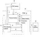
- FIG. 1is a system block diagram of a USB-to-VGA converter constructed in accordance with the present invention
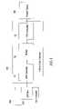
- FIG. 2is a block diagram of a bridge circuit of the USB-to-VGA converter of the present invention
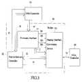
- FIG. 3is a block diagram of a bridge circuit of the USB-to-VGA converter in accordance with a different embodiment of the present invention
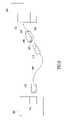
- FIG. 4is a flow chart illustrating a process for a host computer to issue USB display signals to a USB controller
- FIG. 5is a schematic view illustrating an application of the USB-to-VGA converter in connecting a display device to a host computer
- FIG. 6is a schematic view illustrating a different application of the USB-to-VGA converter in connecting a display device to a host computer.
- a USB-to-VGA converter constructed in accordance with the present inventioncomprises a USB controller 10 , a VGA controller 20 and a bridge 30 connected between the USB controller 10 and the VGA controller 20 .
- the USB controller 10is connectable to a USB port 210 of a host computer 200 for receiving USB based display signals from the host computer 200 .
- the VGA controller 20is connectable to a display device 300 whereby the USB-to-VGA converter 100 provides a signal conversion and connection between the host computer 200 and the display device 300 .
- the bridge 30that is connected between the USB controller 10 and the VGA controller 20 receives the USB based display signals from the USB controller 10 in a first-in-first-out (FIFO) manner and converts the USB based display signals into corresponding standard VGA signals which is then applied to the VGA controller 20 .
- the VGA controller 20in turn forwards the VGA signals to the display device 300 for display by the display device 300 .
- the bridge 30comprises a firmware interface 31 , a first-in-first-out (FIFO) controller 32 and a display interface conversion device 33 .
- the firmware interface 31is connected to the USB controller 10 and receives a bus control command A from the USB controller 10 .
- the firmware interface 31is also connected to the display interface conversion device 33 by a control bus B and a data bus C for transmission of a DMA control signal, a firmware control signal and a control command therebetween for allowing the display interface conversion device 33 to convert the USB based display signals into the corresponding VGA signals D which can be of PCI type or AGP type, but is not limited thereto.
- the FIFO controller 32is connected to the USB controller 10 by a data bus E and a control line F.
- the FIFO controller 32issues control instructions to the USB controller 10 via the control line F for controlling the USB controller 10 to forward the USB based display signals received from the host computer 200 to the FIFO controller 32 in a FIFO manner via the data bus E.
- the FIFO controller 32is connected to the display interface conversion device 33 by a data bus G and a control line H whereby the FIFO controller 32 issues FIFO control instruction to the display interface conversion device 33 via the control line H in order to convey the USB based display signals from the FIFO controller 32 to the display interface conversion device 33 in a FIFO manner via the data bus G.
- the display interface conversion device 33then converts the USB based display signals into the corresponding VGA signals D and applies the VGA signals D to the display device 300 .
- FIG. 3shows a block diagram of a different embodiment of the bridge 30 in which the display interface conversion device, which is designated with reference numeral 33 ′ for distinction, is embodied as a PCI interface.
- the firmware interface 31receives a PIO bus control command A′ that is issued by the USB controller 10 .
- the firmware interface 31is connected to the display interface conversion device 33 ′ by a DMA address control line B 1 , a DMA length control line B 2 , a DMA trigger control line B 3 , a firmware trigger control line B 4 and a data bus C whereby the firmware interface 31 controls DMA address, data length and trigger signal of the display interface conversion device 33 ′ and the triggering of the firmware by means of the DMA address control line B 1 , the DMA length control line B 2 , the DMA trigger control line B 3 , and the firmware trigger control line B 4 and forwards control instructions and data to the display interface conversion device 33 ′ via the data bus C.
- the FIFO controller 32is connected to the USB controller 10 by a data bus E and a control line F.
- the FIFO controller 32issues control instructions to the USB controller 10 via the control line F for controlling the USB controller 10 to forward the USB based display signals received from the host computer 200 to the FIFO controller 32 in a FIFO manner via the data bus E.
- the FIFO controller 32is connected to the display interface conversion device 33 ′ by a data bus G and a control line H whereby the FIFO controller 32 issues a FIFO control instruction to the display interface conversion device 33 ′ via the control line H in order to convey the USB based display signals from the FIFO controller 32 to the display interface conversion device 33 ′ in a FIFO manner via the data bus G.
- the display interface conversion device 33 ′based on the control signals including the DMA address, the data length, the trigger signal and the firmware triggering signal issued by the firmware interface 31 via the DMA address control line B 1 , the DMA length control line B 2 , the DMA trigger control line B 3 and the firmware trigger control line B 4 , converts the USB based display signals into the corresponding PCI type VGA signals D′ and applies the VGA signals D′ to the display device 300 .
- the bridge 30 comprised of the USB-to-VGA converter of the present inventionis embodied in for example a FPGA (Field Programmable Gate Array) chip. However, it can also be embodied in a single chip integrated circuit of different form, such as an ASIC, in which the firmware interface 31 , the FIFO controller 32 and the display interface conversion device 33 ( 33 ′) are integrated.
- FPGAField Programmable Gate Array
- FIG. 4shows an operation process of the USB-to-VGA converter 100 working with a host computer 200 to control the display device 300 .
- the operation process discussed hereinis based on the WINDOWS operation system released by Microsoft Company, comprising the following steps:
- step 400application software of the host computer 200 issues a request for display of messages.
- step 410the host computer 200 initiates GD 132 display control function and forward the display messages of the application software to a graphics engine.
- the graphics engineis started in step 420 for processing the messages to be displayed.
- a graphics driveris actuated to process and drive the displayed screen information.
- the informationis transmitted via the USB interface.
- the USB-to-VGA converter 100can work with any computer systems running under any operation systems. No hardware based display card is required inside the computer 200 . The space that is traditionally occupied by the display card inside the computer 200 is thus saved. In addition, no large cable connected between the display device and the host computer is needed.
- FIG. 5shows an application of the USB-to-VGA converter of the present invention in a computer system comprising a display device 300 and a host computer 200 .
- the USB-to-VGA converter 100is encased in and embodied as an “adaptor” 600 .
- the USB controller 10 , the VGA controller 20 and the bridge 30are arranged inside the adaptor 600 .
- the adaptor 600forms a VGA plug 620 releasably mating a signal inlet port 310 of the display device 300 and a USB socket 610 into which a USB plug 510 formed on an end of a USB cable 500 is plugged.
- An opposite end of the USB cable 500forms another USB plug 510 for engaging a USB port 210 of the host computer 200 thereby connecting the host computer 200 to the display device 300 .
- FIG. 6shows a different application of the USB-to-VGA converter of the present invention in a computer system comprising a display device 300 and a host computer 200 connected by a USB cable 500 .
- the USB controller 10 , the VGA controller 20 and the bridge 30 of the USB-to-VGA converter 100 of the present inventionare integrated with a display control circuit 320 built inside the display device 300 .
- the display control circuit 320comprises a USB socket 330 exposed for engagement with a USB plug 510 formed on an end of the USB cable 500 .
- An opposite end of the USB cable 500forms another USB plug 510 for engaging a USB port 210 of the host computer 200 thereby connecting the host computer 200 to the display device 300 .
- the VGA controller 20is coupled to the display control circuit 320 for direct supply of VGA signals to the display device 300 .
- the present inventionis aimed to provide a simple and low cost measure for connecting a host computer to a display device without a hardware based display interface card mounted inside the host computer.
- a USB cablecan simply connect the display device to the host computer and allows for transmission of display signals in USB form that has a broad bandwidth and low signal lose.
- the USB signalis then converted into a VGA signal for proper display by the display device. Costs of the cable itself and the installation of the cable between the computer and the display device are thus substantially reduced. Flexibility of the arrangement of the display device with respect to the computer is also enhanced.
Landscapes
- Engineering & Computer Science (AREA)
- Theoretical Computer Science (AREA)
- Physics & Mathematics (AREA)
- General Physics & Mathematics (AREA)
- Computer Hardware Design (AREA)
- Human Computer Interaction (AREA)
- General Engineering & Computer Science (AREA)
- Information Transfer Systems (AREA)
- Bus Control (AREA)
- Controls And Circuits For Display Device (AREA)
Abstract
Description
Claims (19)
Priority Applications (1)
| Application Number | Priority Date | Filing Date | Title |
|---|---|---|---|
| US10/316,013US7203788B2 (en) | 2002-12-11 | 2002-12-11 | USB-to-VGA converter |
Applications Claiming Priority (1)
| Application Number | Priority Date | Filing Date | Title |
|---|---|---|---|
| US10/316,013US7203788B2 (en) | 2002-12-11 | 2002-12-11 | USB-to-VGA converter |
Publications (2)
| Publication Number | Publication Date |
|---|---|
| US20040117538A1 US20040117538A1 (en) | 2004-06-17 |
| US7203788B2true US7203788B2 (en) | 2007-04-10 |
Family
ID=32505895
Family Applications (1)
| Application Number | Title | Priority Date | Filing Date |
|---|---|---|---|
| US10/316,013Expired - LifetimeUS7203788B2 (en) | 2002-12-11 | 2002-12-11 | USB-to-VGA converter |
Country Status (1)
| Country | Link |
|---|---|
| US (1) | US7203788B2 (en) |
Cited By (9)
| Publication number | Priority date | Publication date | Assignee | Title |
|---|---|---|---|---|
| US20050285863A1 (en)* | 2004-06-25 | 2005-12-29 | Diamond Michael B | Discrete graphics system unit for housing a GPU |
| US20050285864A1 (en)* | 2004-06-25 | 2005-12-29 | Diamond Michael B | Method and system for stand alone graphics independent of computer system form factor |
| US20050285865A1 (en)* | 2004-06-25 | 2005-12-29 | Diamond Michael B | Method and system for a scalable discrete graphics system |
| US20080104297A1 (en)* | 2006-10-26 | 2008-05-01 | Hon Hai Precision Industry Co., Ltd. | Expansion card apparatus |
| US7663633B1 (en) | 2004-06-25 | 2010-02-16 | Nvidia Corporation | Multiple GPU graphics system for implementing cooperative graphics instruction execution |
| US20110001863A1 (en)* | 2009-07-02 | 2011-01-06 | Hon Hai Precision Industry Co., Ltd. | Display with video camera |
| US20110019156A1 (en)* | 2009-07-23 | 2011-01-27 | Young Optics Inc. | Projection system and method thereof |
| DE102011117557A1 (en) | 2011-08-17 | 2013-02-21 | Magic Control Technology Corp. | Device for sharing media |
| US9934168B2 (en) | 2013-10-29 | 2018-04-03 | Userful Corporation | Method and system of connecting and switching grouped input and output devices between computers |
Families Citing this family (18)
| Publication number | Priority date | Publication date | Assignee | Title |
|---|---|---|---|---|
| US20050018244A1 (en)* | 2003-03-20 | 2005-01-27 | Kia Silverbrook | Display device having a flat panel display and a print media path in a plane that is substantially parallel to a plane defined by the flat panel display |
| US7229226B2 (en)* | 2003-03-20 | 2007-06-12 | Silverbrook Research Pty Ltd | Display device having pagewidth printhead adjacent lower edge of housing |
| US7419259B2 (en)* | 2003-03-20 | 2008-09-02 | Silverbrook Research Pty Ltd | Display device having print media path parallel to plane of flat panel display in at least one direction |
| AU2003901297A0 (en)* | 2003-03-20 | 2003-04-03 | Silverbrook Research Pty Ltd | Systems and apparatus (fpd001) |
| US7125185B2 (en)* | 2003-03-20 | 2006-10-24 | Silverbrook Research Pty Ltd | Display device having pagewidth printer |
| US20050172051A1 (en)* | 2004-01-29 | 2005-08-04 | Chi-Tung Chang | Method of data transmission |
| GB2432684A (en)* | 2005-07-13 | 2007-05-30 | Magic Control Technology Corp | USB-to-VGA Converter |
| JP2009518902A (en)* | 2005-12-05 | 2009-05-07 | 聯想(北京)有限公司 | Wireless display system and method |
| JP5148505B2 (en) | 2005-12-14 | 2013-02-20 | ▲聯▼想(北京)有限公司 | Display system and method |
| KR20100123138A (en)* | 2009-05-14 | 2010-11-24 | 삼성전자주식회사 | Display apparatus |
| GB2484736B (en)* | 2010-10-22 | 2014-11-05 | Displaylink Uk Ltd | Image generation |
| GB2486431B (en)* | 2010-12-14 | 2013-10-09 | Displaylink Uk Ltd | Scaling of graphical data |
| TWI457761B (en)* | 2011-12-14 | 2014-10-21 | A system for accelerating signal transmission and a method thereof | |
| CN103389879B (en)* | 2012-05-10 | 2016-08-17 | 慧荣科技股份有限公司 | Electronic device and method for transmitting data from electronic device to display device |
| US9165538B2 (en) | 2013-03-13 | 2015-10-20 | Displaylink (Uk) Limited | Image generation |
| CN104503723B (en)* | 2014-12-24 | 2018-01-02 | 北京凯视达科技有限公司 | The bearing calibration of VGA signal phases and device |
| WO2016175480A1 (en) | 2015-04-30 | 2016-11-03 | Samsung Electronics Co., Ltd. | Electronic device, adapter device, and video data processing method thereof |
| TWI819670B (en)* | 2022-06-22 | 2023-10-21 | 瑞昱半導體股份有限公司 | Control device and related display system |
Citations (8)
| Publication number | Priority date | Publication date | Assignee | Title |
|---|---|---|---|---|
| US6175789B1 (en)* | 1995-11-29 | 2001-01-16 | Microsoft Corporation | Vehicle computer system with open platform architecture |
| US6285398B1 (en)* | 1997-11-17 | 2001-09-04 | Sony Corporation | Charge-coupled device video camera with raw data format output and software implemented camera signal processing |
| US20010032280A1 (en)* | 1996-11-07 | 2001-10-18 | Hitachi, Ltd. | Interface switching apparatus and switching control method |
| US20020135584A1 (en)* | 2000-04-03 | 2002-09-26 | Lee Eun Seog | Video graphic adaptor for driving sub-monitor of dual monitor using usb port |
| US6624797B1 (en)* | 1999-03-29 | 2003-09-23 | Ati International Srl | Method and apparatus for providing video and control to a monitor |
| US6629926B1 (en)* | 1997-12-31 | 2003-10-07 | Acuson Corporation | Ultrasonic system and method for storing data |
| US20040021615A1 (en) | 2002-07-30 | 2004-02-05 | Ncr Corporation | Methods and apparatus for improved display of visual data for point of sale terminals |
| US20040153778A1 (en)* | 2002-06-12 | 2004-08-05 | Ati Technologies, Inc. | Method, system and software for configuring a graphics processing communication mode |
- 2002
- 2002-12-11USUS10/316,013patent/US7203788B2/ennot_activeExpired - Lifetime
Patent Citations (9)
| Publication number | Priority date | Publication date | Assignee | Title |
|---|---|---|---|---|
| US6175789B1 (en)* | 1995-11-29 | 2001-01-16 | Microsoft Corporation | Vehicle computer system with open platform architecture |
| US6202008B1 (en)* | 1995-11-29 | 2001-03-13 | Microsoft Corporation | Vehicle computer system with wireless internet connectivity |
| US20010032280A1 (en)* | 1996-11-07 | 2001-10-18 | Hitachi, Ltd. | Interface switching apparatus and switching control method |
| US6285398B1 (en)* | 1997-11-17 | 2001-09-04 | Sony Corporation | Charge-coupled device video camera with raw data format output and software implemented camera signal processing |
| US6629926B1 (en)* | 1997-12-31 | 2003-10-07 | Acuson Corporation | Ultrasonic system and method for storing data |
| US6624797B1 (en)* | 1999-03-29 | 2003-09-23 | Ati International Srl | Method and apparatus for providing video and control to a monitor |
| US20020135584A1 (en)* | 2000-04-03 | 2002-09-26 | Lee Eun Seog | Video graphic adaptor for driving sub-monitor of dual monitor using usb port |
| US20040153778A1 (en)* | 2002-06-12 | 2004-08-05 | Ati Technologies, Inc. | Method, system and software for configuring a graphics processing communication mode |
| US20040021615A1 (en) | 2002-07-30 | 2004-02-05 | Ncr Corporation | Methods and apparatus for improved display of visual data for point of sale terminals |
Non-Patent Citations (2)
| Title |
|---|
| National Semiconductor, USBN9602 (Universal Serial Bus) Full Speed Function Controller With DMA Support, Nov. 1998. |
| Subramaniam, K, "VinChip Announces Release of USB-PCI Device Bridge IP", San Jose, CA. |
Cited By (14)
| Publication number | Priority date | Publication date | Assignee | Title |
|---|---|---|---|---|
| US8411093B2 (en)* | 2004-06-25 | 2013-04-02 | Nvidia Corporation | Method and system for stand alone graphics independent of computer system form factor |
| US20050285864A1 (en)* | 2004-06-25 | 2005-12-29 | Diamond Michael B | Method and system for stand alone graphics independent of computer system form factor |
| US20050285865A1 (en)* | 2004-06-25 | 2005-12-29 | Diamond Michael B | Method and system for a scalable discrete graphics system |
| US20050285863A1 (en)* | 2004-06-25 | 2005-12-29 | Diamond Michael B | Discrete graphics system unit for housing a GPU |
| US7663633B1 (en) | 2004-06-25 | 2010-02-16 | Nvidia Corporation | Multiple GPU graphics system for implementing cooperative graphics instruction execution |
| US8941668B2 (en)* | 2004-06-25 | 2015-01-27 | Nvidia Corporation | Method and system for a scalable discrete graphics system |
| US8446417B2 (en) | 2004-06-25 | 2013-05-21 | Nvidia Corporation | Discrete graphics system unit for housing a GPU |
| US20080104297A1 (en)* | 2006-10-26 | 2008-05-01 | Hon Hai Precision Industry Co., Ltd. | Expansion card apparatus |
| US7698488B2 (en)* | 2006-10-26 | 2010-04-13 | Hon Hai Precision Industry Co., Ltd. | Expansion apparatus for expansion card on motherboard |
| US20110001863A1 (en)* | 2009-07-02 | 2011-01-06 | Hon Hai Precision Industry Co., Ltd. | Display with video camera |
| US20110019156A1 (en)* | 2009-07-23 | 2011-01-27 | Young Optics Inc. | Projection system and method thereof |
| DE102011117557A1 (en) | 2011-08-17 | 2013-02-21 | Magic Control Technology Corp. | Device for sharing media |
| DE102011117557B4 (en) | 2011-08-17 | 2024-06-06 | Magic Control Technology Corp. | Device for sharing media |
| US9934168B2 (en) | 2013-10-29 | 2018-04-03 | Userful Corporation | Method and system of connecting and switching grouped input and output devices between computers |
Also Published As
| Publication number | Publication date |
|---|---|
| US20040117538A1 (en) | 2004-06-17 |
Similar Documents
| Publication | Publication Date | Title |
|---|---|---|
| US7203788B2 (en) | USB-to-VGA converter | |
| JP4753520B2 (en) | Dual monitor auxiliary monitor using USB port-Video graphics adapter for driving- | |
| US7752342B2 (en) | Interface integrated circuit device for a USB connection | |
| EP0778516B1 (en) | Hardware independent display device interface | |
| US6873306B2 (en) | Display controller architecture for portable computers | |
| JP2003209920A (en) | DVI optical extension cable connection and external power input confirmation device | |
| US6415337B1 (en) | Plug-and-play interface circuit with visual display | |
| JP3100747U (en) | USB to VGA interface converter | |
| CN2599646Y (en) | USB-to-VGA interface conversion device | |
| US7158140B1 (en) | Method and apparatus for rendering an image in a video graphics adapter | |
| TWI384371B (en) | Interface card for extending input/output interface | |
| CN209015704U (en) | An interface circuit and display device | |
| GB2432684A (en) | USB-to-VGA Converter | |
| US7818481B2 (en) | Computer system and monitor with peripheral interfaces | |
| JP2008228041A (en) | Signal transmitter and transmission module | |
| NL1033361C2 (en) | USB to VGA converter, has bridge for converting USB based display signals into corresponding video graphic signals in FIFO manner for displaying in display device | |
| KR200405501Y1 (en) | BA interface switch | |
| CN1667568A (en) | Interface devices and graphics cards | |
| KR100743900B1 (en) | Computer system with USB-based monitor | |
| KR200410467Y1 (en) | Computer system with USB-based monitor | |
| JP2001202068A (en) | Monitor with bidirectional interface | |
| US20060238964A1 (en) | Display apparatus for a multi-display card and displaying method of the same | |
| KR20020059552A (en) | Computer system | |
| CN216671172U (en) | Control device of liquid crystal display of systematized chip | |
| JP3501722B2 (en) | Image display device |
Legal Events
| Date | Code | Title | Description |
|---|---|---|---|
| AS | Assignment | Owner name:MAGIC CONTROL TECHNOLOGY CORPORATION, TAIWAN Free format text:ASSIGNMENT OF ASSIGNORS INTEREST;ASSIGNOR:LIU, PEI-CHUNG;REEL/FRAME:013564/0969 Effective date:20021203 | |
| STCF | Information on status: patent grant | Free format text:PATENTED CASE | |
| FPAY | Fee payment | Year of fee payment:4 | |
| FPAY | Fee payment | Year of fee payment:8 | |
| FEPP | Fee payment procedure | Free format text:MAINTENANCE FEE REMINDER MAILED (ORIGINAL EVENT CODE: REM.); ENTITY STATUS OF PATENT OWNER: SMALL ENTITY | |
| AS | Assignment | Owner name:KAIJET TECHNOLOGY INTERNATIONAL LIMITED, INC., GEO Free format text:ASSIGNMENT OF ASSIGNORS INTEREST;ASSIGNOR:MAGIC CONTROL TECHNOLOGY CORPORATION;REEL/FRAME:048623/0071 Effective date:20180822 | |
| PRDP | Patent reinstated due to the acceptance of a late maintenance fee | Effective date:20190412 | |
| FEPP | Fee payment procedure | Free format text:PETITION RELATED TO MAINTENANCE FEES GRANTED (ORIGINAL EVENT CODE: PMFG); ENTITY STATUS OF PATENT OWNER: SMALL ENTITY Free format text:SURCHARGE, PETITION TO ACCEPT PYMT AFTER EXP, UNINTENTIONAL. (ORIGINAL EVENT CODE: M2558); ENTITY STATUS OF PATENT OWNER: SMALL ENTITY Free format text:PETITION RELATED TO MAINTENANCE FEES FILED (ORIGINAL EVENT CODE: PMFP); ENTITY STATUS OF PATENT OWNER: SMALL ENTITY | |
| MAFP | Maintenance fee payment | Free format text:PAYMENT OF MAINTENANCE FEE, 12TH YR, SMALL ENTITY (ORIGINAL EVENT CODE: M2553); ENTITY STATUS OF PATENT OWNER: SMALL ENTITY Year of fee payment:12 |